

Page 1
Instruction Manual
HI 8510- HI 8512
HI 8710 - HI 8711
HI 8720 - HI 931500
HI931501-HI932500
Panel - Mounted
ORP - pH Indicators
and Controllers
HI 8720E
ORP
mV
DOSAGE
OXID.
MEA
SURE
0 mV
TEST
These Instruments are in Compliance with the CE Directives
http://www.hannainst.com
REDUC.
SET
∆AL
500 mV
TEST
SLOPE
∆AL
COARSE
SET
FINE
1
Page 2

Dear Customer,
Thank you for choosing a Hanna Instruments
Product.
Please read this instruction manual carefully
before using the instrument.
This manual will provide you with all the necessary information for the correct use of the
instrument, as well as a precise idea of its
versatility in a wide range of applications.
These instruments are in compliance with
directives.
TABLE OF CONTENTS
Preliminary Examination ............................. 3
General Description..................................... 3
Mechanical Dimensions .............................. 5
Functional Description HI 8510.................... 6
Functional Description HI 8512.................... 9
Functional Description HI 8710.................. 12
Functional Description HI 8711.................. 16
Functional Description HI 8720.................. 20
Functional Description HI 931500 .............. 24
Functional Description HI 931501 .............. 26
Functional Description HI 932500 .............. 29
Specifications HI 8510 and HI 8512 ........... 31
Specifications HI 8710 and HI 8711 ........... 32
Specifications HI 8720 and HI 931500 ....... 33
Specifications HI 931501 and HI 932500.... 34
Initial Preparation ...................................... 35
Operational Guide ..................................... 38
pH Calibration ........................................... 42
pH V alues at V arious T emperature............. 44
pH Diagnostic Tests.................................. 45
ORP Diagnostic Tests ............................... 47
LED Indication........................................... 48
T aking Redox Measurements .................... 49
Electrode Conditioning and Maintenance... 5 0
Suggested Installations ............................. 57
Accessories.............................................. 59
Warranty ................................................... 65
CE Declaration of Conformity .................... 66
2
Page 3

PRELIMINARY EXAMINATION
Remove the instrument from the packing
material and examine it carefully to make
sure that no damage has occurred during
shipping. If there is any noticeable damage,
notify your Dealer.
Note: Save all packing materials until you
are sure that the instrument functions
correctly. All defective items must be
returned in the original packing materials
together with the supplied accessories.
GENERAL DESCRIPTION
HI 8510, HI 8512, HI 8710, HI 8711, HI 8720,
HI 931500, HI931501 and HI 932500 are pH-
ORP panel-mounted indicators and controllers designed for simplicity of use in a wide
range of industrial process applications.
The models are designed with DIN standard
panel mount with membrane keypads on the
front panel, a large LCD display and
autodiagnostic functions (not HI 931500,
HI 931501 and HI 932500).
Connections to the power supply, contacts
and recorders are made through screw terminals on the rear panel.
Two models are available for HI 8510, HI8711,
HI 8512, HI 8520. The E-model accepts input
direct from the pH or ORP electrode, while
the T-model accepts a 2-wire current loop of
4 to 20mA from a pH or ORP transmitter.
HI 931500, HI 931501 and HI 932500 are
equipped with a BNC socket to connect a
pH-ORP electrode.
Other features include: recorder output in 0
to 20mA or 4 to 20 mA; LED indicators
which identify the controller mode.
3
Page 4

Using the pH indicators in conjunction with a
4-20mA output pH transmitter HI 8614 or
HI 8614L (with LCD display) and using the
ORP indicators in conjunction with a 4-20 mA
output ORP transmitter HI 8615 or HI 8615L
(with LCD display) will assure you of a strong,
interference-free signal at distances up to
300 m (1000 ft).
All instruments are supplied with a plastic
transparent front cover and mounting brackets (electrode and mains cable excluded).
4
Page 5
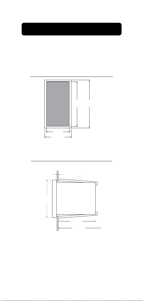
MECHANICAL DIMENSIONS
The meters have a DIN 43 700 casing in
black anodized aluminum. Front and back of
the instruments are supplied with shockproof
ABS plastic and a transparent protective cover
for the front panel.
Front view of the panel-mounted unit.
141mm
144mm
5.55"
5.67"
69mm
2.71"
72mm
2.83"
These dimensions show the cutout size for
the installation.
Side view of the panel-mounted unit.
144mm
5.67"
0.25/4mm
0.01/0.160"
135mm
5.31"
190mm MIN
7.50"
ADJUSTABLE
LOCATION
BRACKET
Adjustable location brackets (supplied with
the meter) allow the indicator to slide into the
cutout and will hold the unit securely in place.
190 mm (7.50") is the minimum amount of
room required to install the indicator with the
cables connected.
5
Page 6
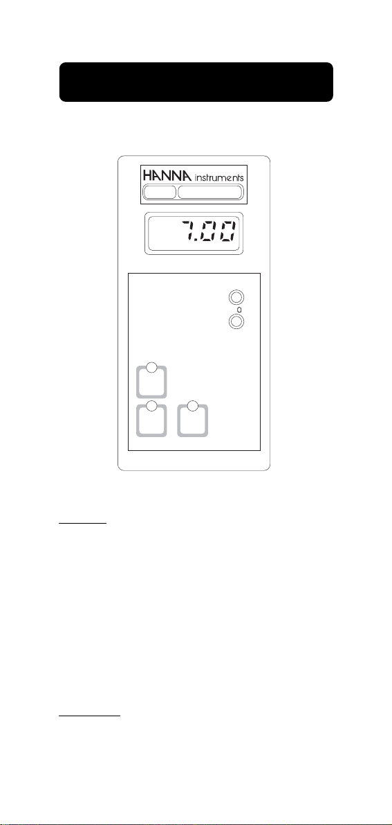
FUNCTIONAL DESCRIPTION HI 8510
pH INDICATOR
FRONT PANEL
pH
HI 8510E
pH
SLOPE
∆
SENSOR
TEST
pH 7
TEST
pH 4
TEST
Keypad
SENSOR TEST
To display the mV response of the electrode in
order to verify its working condition
pH 7 TEST
To verify the internal circuit of the meter in terms
of Offset compensation
pH 4 TEST
To verify the amplifier circuit of the meter
Trimmers
∆∆
∆O For Offset calibration
∆∆
SLOPE For Slope calibration
6
Page 7
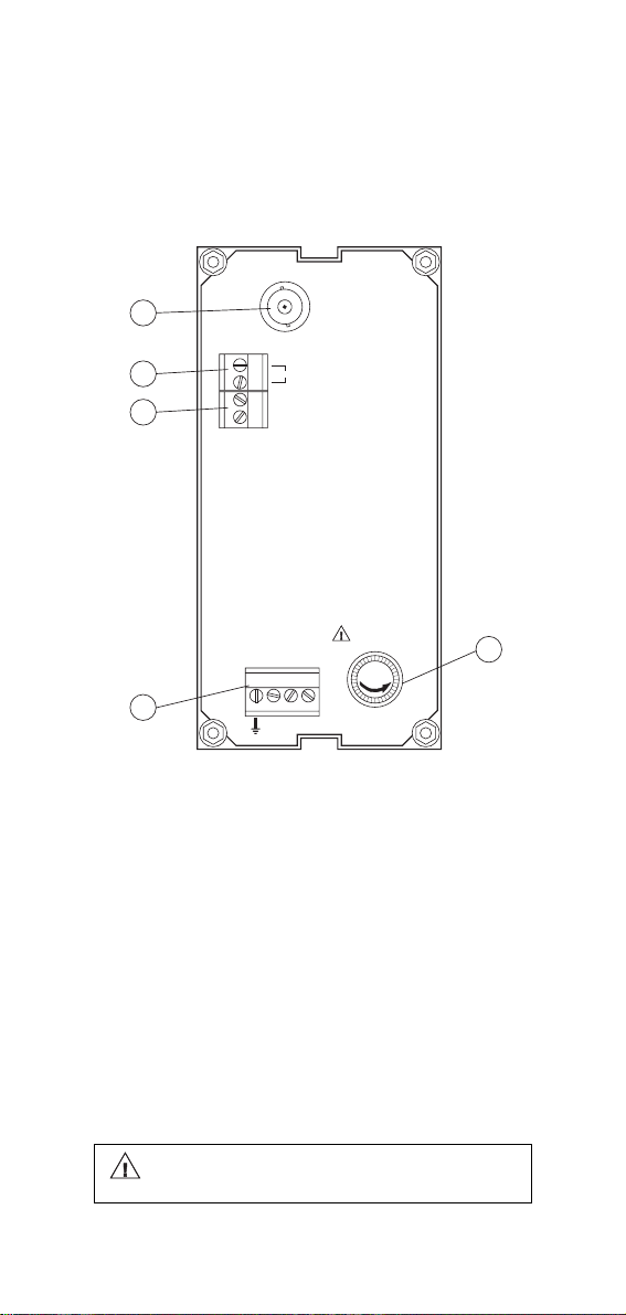
REAR PANEL HI 8510E
5
ELECTRODE
INPUT
4
3
2
PT100
+
mA OUT
-
220
FUSE
FUSE
L
110
1
1. Fuse Holder
2. Power supply
3. Recorder output
4. Connections for PT100 temperature sensor
5. BNC socket for pH electrode.
Unplug the instrument from the power
supply before replacing the fuse.
7
Page 8
REAR PANEL HI 8510T
1. Fuse Holder
2. Power supply
3. Recorder output
4. Connections to the transmitter.
Unplug the instrument from the power
supply before replacing the fuse.
8
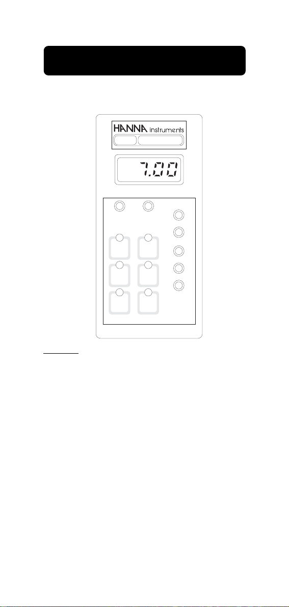
Page 9
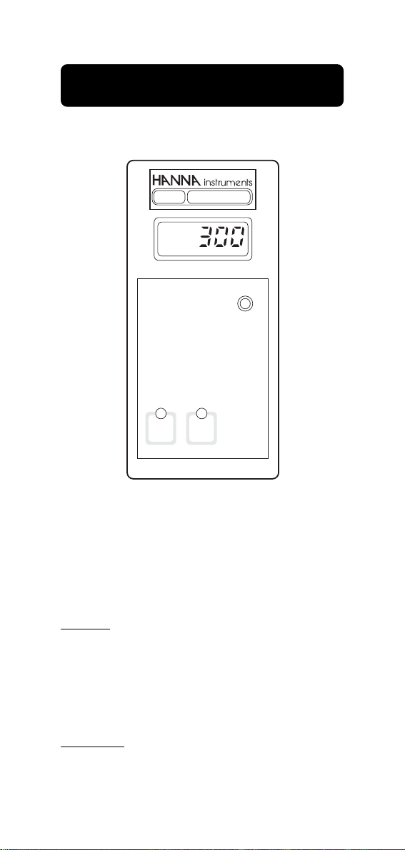
FUNCTIONAL DESCRIPTION HI 8512
ORP INDICATOR
FRONT PANEL
HI 8512E
ORP
mV
SLOPE
500 mV
0 mV
TEST
TEST
Keypad
0 mV TEST To verify the instrument cali-
bration at point 0
500 mV TEST To verify the slope at point
500 mV
Trimmers
SLOPE For Slope calibration
9
Page 10
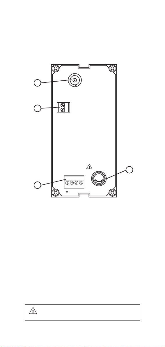
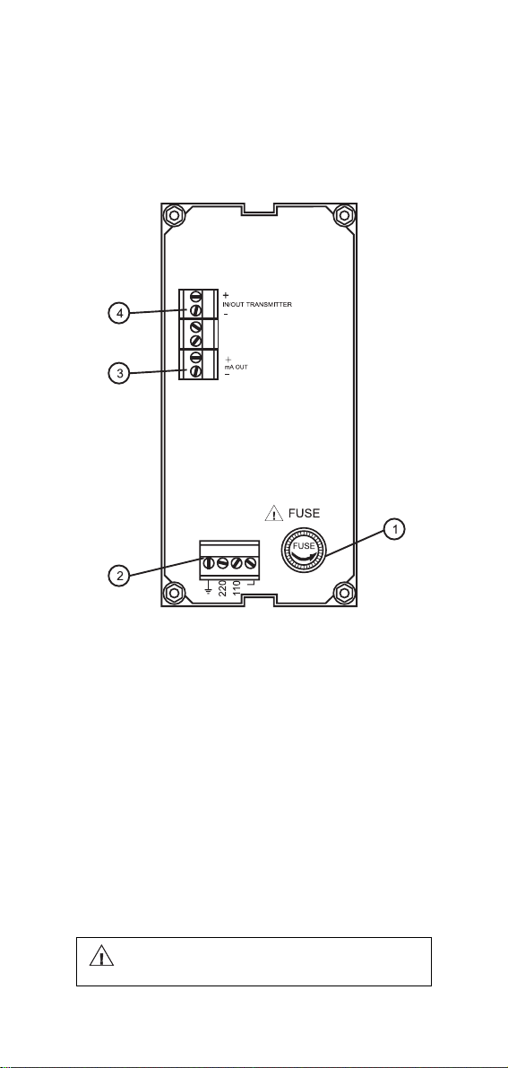
REAR PANEL HI 8512E
4
+
3
mA OUT
-
ELECTRODE
INPUT
FUSE
FUSE
2
220
L
110
1. Fuse Holder
2. Power supply
3. Recorder output
4. BNC socket for ORP electrode.
Unplug the instrument from the power
supply before replacing the fuse.
10
1
Page 11

REAR PANEL HI 8512T
1. Fuse Holder
2. Power supply
3. Recorder output
4. Connections to the transmitter.
Unplug the instrument from the power
supply before replacing the fuse.
11
Page 12
FUNCTIONAL DESCRIPTION HI 8710
pH CONTROLLER WITH ALARM
FRONT PANEL
pH
HI 8710E
pH
BASE
SET
∆AL
pH 4
TEST
SLOPE
∆
0
∆AL
COARSE
SET
FINE
ACID
MEA
SURE
SENSOR
TEST
pH 7
TEST
Keypad
SET To set the working point of pH
dosage
MEASURE To set HI 8710 on measure-
ment mode and to enable the
diagnostic tests
SENSOR TEST To display the mV response
of the electrode in order to verify
its working condition
∆∆
∆AL To display and set the toler-
∆∆
ance of the alarm points
pH 7 TEST To verify the internal circuit of
the meter in terms of Offset
compensation
pH 4 TEST To verify the amplifier circuit of
the meter
12
Page 13

Trimmers
∆∆
∆O For Offset calibration
∆∆
SLOPE For Slope calibration
∆∆
∆AL To set the tolerance of the
∆∆
alarm
SET/COARSE To coarsely adjust the set point
SET/FINE To finely adjust the set point
Leds
ACID To show the acid dosage is
active
BASE To show the basic dosage is
active
∆∆
∆AL (blinking) To show the alarm is active
∆∆
13
Page 14
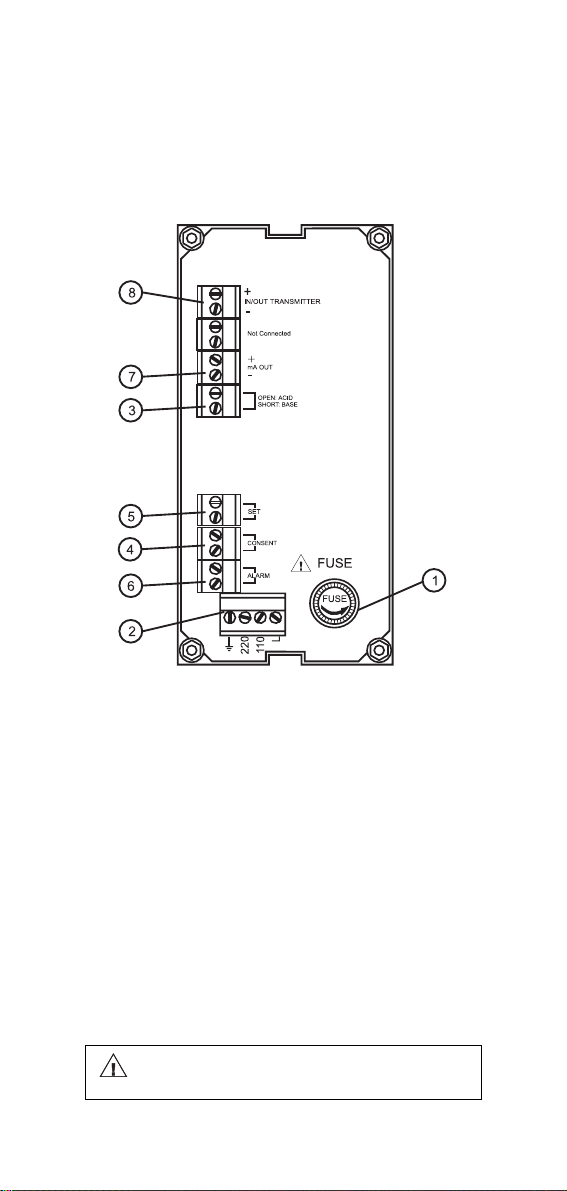
REAR PANEL HI 8710E
9
ELECTRODE
INPUT
8
7
3
5
4
6
2
PT100
+
mA OUT
-
OPEN: ACID
SHORT: BASE
SET
CONSENT
ALARM
220
FUSE
FUSE
L
110
1
1. Fuse Holder
2. Power supply
3. Acid/Basic dosage selection
4. Reductant or oxidant dosage consent
5. Connections for dosing pump
6. Alarm contacts
7. Recorder output
8. Connections for PT100 temperature sensor
9. BNC socket for pH electrode.
Unplug the instrument from the power
supply before replacing the fuse.
14
Page 15
REAR PANEL HI 8710T
1. Fuse Holder
2. Power supply
3. Acid/Basic dosage selection
4. Reductant or oxidant dosage consent
5. Connections for dosing pump
6. Alarm contacts
7. Recorder output
8. Connections to the transmitter.
Unplug the instrument from the power
supply before replacing the fuse.
15
Page 16
FUNCTIONAL DESCRIPTION HI 8711
DUAL OUTPUT pH CONTROLLER
FRONT PANEL
pH
HI 8711E
pH
SLOPE
ACID
SET
MEA
SURE
SENSOR
TEST
pH 7
TEST
HI 8711E
BASE
SET
∆AL
pH 4
TEST
∆
∆AL
COARSE
ACID SET
FINE
COARSE
BASE SET
FINE
Keypad
ACID SET To set the working point
of acid dosage
BASE SET To set the working point
of basic dosage
MEASURE To set HI 8711 on mea-
surement mode and to enable the diagnostic tests
SENSOR TEST To display the mV re-
sponse of the electrode to
verify its working condition.
∆∆
∆Al To display and to set the
∆∆
tolerance of the alarm
points
16
Page 17

pH 7 TEST To verify the internal cir-
cuit of the meter in terms
of Offset compensation
pH 4 TEST To verify the amplifier cir-
cuit of the meter
Trimmers
∆∆
∆O For Offset calibration
∆∆
SLOPE For Slope calibration
∆∆
∆AL To set the tolerance of
∆∆
the alarm
ACID SET/COARSE To coarsely adjust the
acid set point
ACID SET/FINE To finely adjust the
acid set point
BASE SET/COARSE To coarsely adjust the
basic set point
BASE SET/FINE To finely adjust the ba-
sic set point
Leds
ACID SET (Blinking) To show the acid dos-
age is active
BASE SET (Blinking) To show the basic
dosage is active
∆∆
∆AL (Blinking) To show the alarm is
∆∆
active
17
Page 18
REAR PANEL HI 8711E
8
ELECTRODE
INPUT
7
6
4
3
5
2
PT100
+
mA OUT
-
BASE
ACID
ALARM
220
FUSE
FUSE
L
110
1
1. Fuse Holder
2. Power supply
3. Connections for dosing pump for acid
4. Connections for dosing pump for base
5. Alarm contacts
6. Recorder output
7. Connections for PT100 temperature sensor
8. BNC socket for pH electrode.
Unplug the instrument from the power
supply before replacing the fuse.
18
Page 19

REAR PANEL HI 8711T
1. Fuse Holder
2. Power supply
3. Connections for dosing pump for acid
4. Connections for dosing pump for base
5. Alarm contacts
6. Recorder output
7. Connections to the transmitter.
Unplug the instrument from the power
supply before replacing the fuse.
19
Page 20
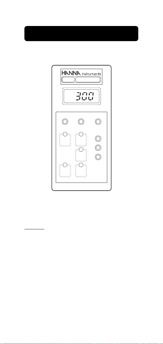
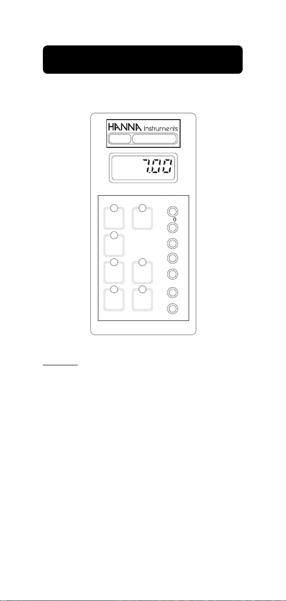
FUNCTIONAL DESCRIPTION HI 8720
ORP CONTROLLER
FRONT PANEL
HI 8720E
ORP
mV
SLOPEDOSAGE
OXID. REDUC.
SET
∆AL
∆AL
COARSE
SET
FINE
MEA
SURE
0 mV
TEST
500 mV
TEST
Keypad
SET To set the working point of ORP
dosage
MEASURE To set HI 8720 on measurement
mode and to enable the diagnostic tests
∆∆
∆Al To display and to set the toler-
∆∆
ance of the alarm points
0 mV TEST To verify the instrument calibra-
tion at point 0
500 mV TEST To verify the slope at point
500 mV
20
Page 21

Trimmers
SLOPE For Slope calibration
∆∆
∆AL To display and set the tolerance
∆∆
of the alarm points
SET/COARSE To coarsely adjust the set
point
SET/FINE To finely adjust the set point
Leds
OXID To show the oxidant dosage is
active
REDUC To show the reductant dosage is
active
∆∆
∆AL (blinking) To show the alarm is active
∆∆
21
Page 22

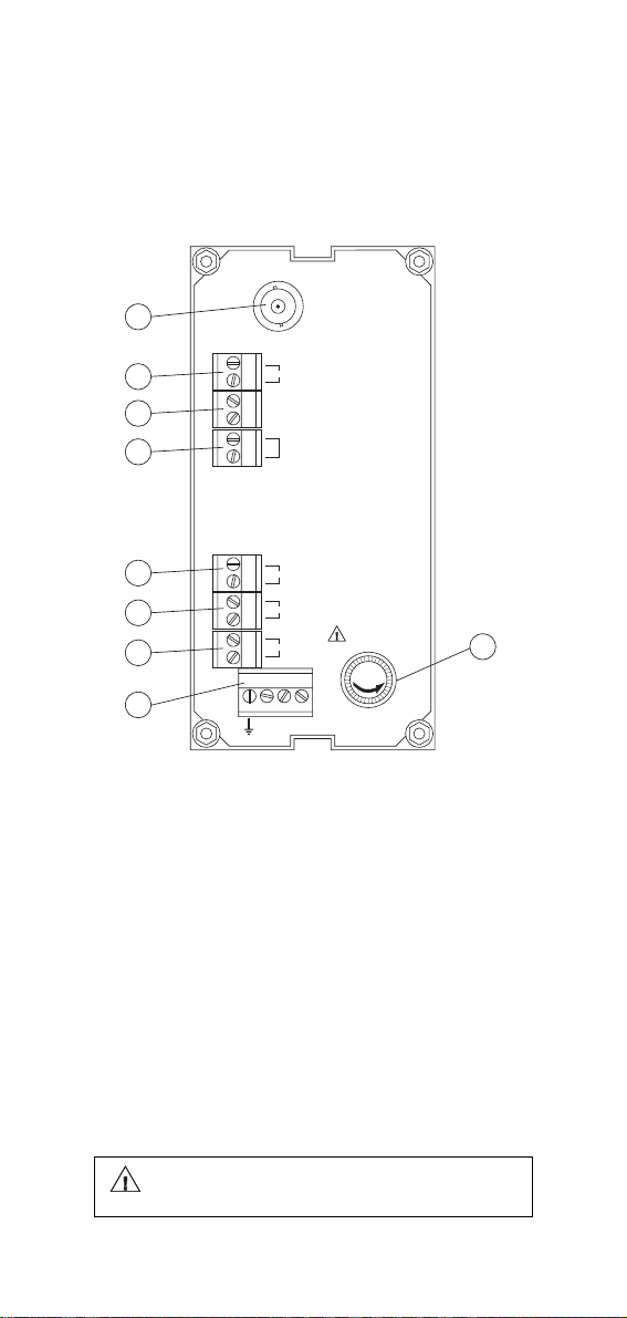
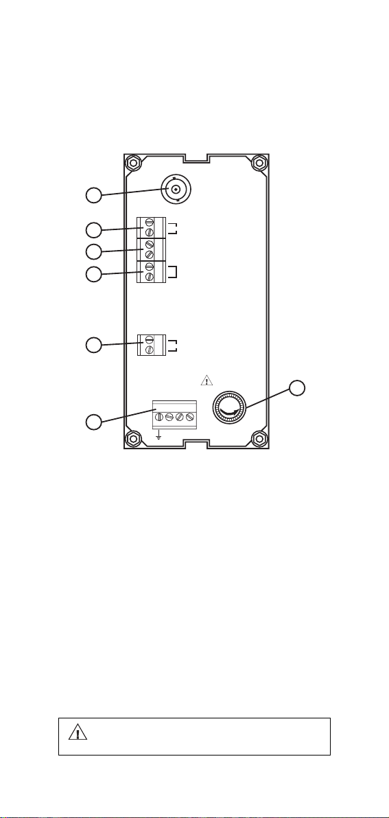
REAR PANEL HI 8720E
8
ELECTRODE
INPUT
4
7
3
5
6
2
CONSENT
+
mA OUT
-
OPEN: OXD
SHORT: RDX
SET
ALARM
110
220
FUSE
FUSE
L
1. Fuse Holder
2. Power supply
3. Oxidant/Reductant dosage selection
4. Oxidant or reductant dosage consent
5. Connections for dosing pump
6. Alarm contacts
7. Recorder output
8. BNC socket for ORP electrode.
1
Unplug the instrument from the power
supply before replacing the fuse.
22
Page 23

REAR PANEL HI 8720T
1. Fuse Holder
2. Power supply
3. Oxidant/Reductant dosage selection
4. Oxidant or Reductant dosage consent
5. Connections for dosing pump
6. Alarm contacts
7. Recorder output
8. Connections to the transmitter.
Unplug the instrument from the power
supply before replacing the fuse.
23
Page 24

FUNCTIONAL DESCRIPTION HI 931500
SINGLE OUTPUT pH CONTROLLER
FRONT PANEL
rum n
SET
e
s
SLOPE
∆O
COARSE
SET
FINE
ins
pH
DOSAGE
ACID BASE
MEA
SURE
HI 931500
pH Process
Controller
Keypad
SET To set the working point of pH
dosage
MEASURE To set HI 931500 on measure-
ment mode
Trimmers
∆∆
∆O For Offset calibration
∆∆
SLOPE For Slope calibration
SET/COARSE To coarsely adjust the set point
SET/FINE To finely adjust the set point
Leds
ACID To show the acid dosage is
active
BASE To show the basic dosage is
active
24
Page 25

REAR PANEL HI 931500
8
ELECTRODE
INPUT
7
6
4
5
3
PT100
+
mA OUT
-
OPEN : ACID
SHORT : BASE
SET
CONSENT
FUSE
FUSE
1
2
L
110
220
1. Fuse Holder
2. Power supply
3. Reductant or oxidant dosage consent
4. Acid/Basic dosage selection
5. Connections for Dosing Pumps
6. Recorder output
7. Connections for PT100 temperature sensor
8. BNC socket for pH electrode.
Unplug the instrument from the power
supply before replacing the fuse.
25
Page 26

FUNCTIONAL DESCRIPTION HI 931501
DUAL OUTPUT pH CONTROLLER
FRONT PANEL
rum n
BASE
SET
s
e
SLOPE
∆O
COARSE
ACID SET
FINE
COARSE
BASE SET
FINE
pH
DOSAGE
ACID
SET
MEA
SURE
HI 931501
pH Process
Controller
ins
Keypad
ACID SET To set the working point of acid
dosage
BASE SET To set the working point of basic
dosage
MEASURE To set HI 931501 on measure-
ment mode
Trimmers
∆∆
∆O For Offset calibration
∆∆
SLOPE For Slope calibration
ACID SET/COARSE To coarsely adjust the
acid set point
26
Page 27

ACID SET/FINE To finely adjust the
acid set point
BASE SET/COARSE To coarsely adjust the
basic set point
BASE SET/FINE To finely adjust the ba-
sic set point
Leds
ACID SET (Blinking) To show the acid dos-
age is active
BASE SET (Blinking) To show the basic
dosage is active
MEASURE To show the meter is on mea-
surement mode
27
Page 28

REAR PANEL HI 931501
7
ELECTRODE
INPUT
6
PT100
+
mA OUT
-
5
4
3
2
BASE
ACID
220
FUSE
FUSE
L
110
1. Fuse Holder
2. Power supply
3. Connections for dosing pump for acid
4. Connections for dosing pump for base
5. Recorder output
6. Connections for PT100 temperature sensor
7. BNC socket for pH electrode.
1
Unplug the instrument from the power
supply before replacing the fuse.
28
Page 29

FUNCTIONAL DESCRIPTION HI 932500
ORP CONTROLLER
FRONT PANEL
mV
DOSAGE
OXID.
MEA
SURE
HI 932500
ORP Process
Controller
SLOPE
REDUC.
SET
COARSE
SET
FINE
Keypad
SET To set the working point of ORP
dosage
MEASURE To set HI 932500 on measure-
ment mode
Trimmers
SLOPE For Slope calibration
SET/COARSE To coarsely adjust the ORP
set point
SET/FINE To finely adjust the ORP set
point
Leds
OXID To show the oxidant dosage is
active
REDUC To show the reductant dosage
is active
29
Page 30
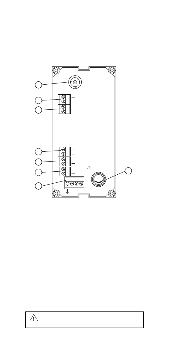
REAR PANEL HI 932500
ELECTRODE
7
INPUT
3
6
4
5
2
CONSENT
+
mA OUT
-
OPEN: OXD
SHORT: RDX
SET
220
FUSE
FUSE
L
110
1. Fuse Holder
2. Power supply
3. Oxidant or reductant dosage consent
4. Oxidant/Reductant dosage selection
5. Connections for dosing pump
6. Recorder output
7. BNC socket for ORP electrode.
1
Unplug the instrument from the power
supply before replacing the fuse.
30
Page 31

SPECIFICATIONS HI 8510
HI 8510E HI 8510T
Range 0.00 to 14.00 pH
Resolution 0.01 pH
Accuracy ±0.02 pH ±0.5%
Typical EMC ±0.1 pH ±0.1 pH
Deviation ±0.2 mA ±0.2 mA
Installation Cat. II
Input 1012 Ohm 4 to 20 mA
Calibration Offset: ±2 pH ∆O trimmer
Temperature Fixed or automatic with PT100
Compensation from 0 to 100°C
Readout 4-digit LCD plus graphic symbols
Recorder Output 0 to 20 mA or 4 to 20 mA (isolated)
Power Supply 110/115 V or 220/240 V; 50/60 Hz
Environment -10 to 50°C (14 to 122°F)
Weight 1 kg (2.2 lb.)
Slope: 80 to 110% Slope trimmer
SPECIFICATIONS HI 8512
HI 8512E HI 8512T
Range -1000 to +1000 mV
Resolution 1 mV
Accuracy ±5 mV ±0.5%
Typical EMC ±6 mV ±6 mV
Deviation ±0.2 mA ±0.2 mA
Installation Cat. II
Input 1012 Ohm 4 to 20 mA
Calibration Slope: 90 to 110% slope trimmer
Readout 4-digit LCD plus graphic symbols
Recorder Output 0 to 20 mA or 4 to 20 mA (isolated)
Power Supply 110/115 V or 220/240 V; 50/60 Hz
Environment -10 to 50°C (14 to 122°F)
Weight 1 kg (2.2 lb.)
31
Page 32

SPECIFICATIONS HI 8710
HI 8710E HI 8710T
Range 0.00 to 14.00 pH
Resolution 0.01 pH
Accuracy ±0.02 pH ±0.5%
Typical EMC ±0.1 pH ±0.1 pH
Deviation ±0.2 mA ±0.2 mA
Installation Cat. II
Input 1012 Ohm 4 to 20 mA
Calibration Offset: ±2 pH ∆O trimmer
Temperature Fixed or automatic with PT100
Compensation from 0 to 100°C
Set Point Relay One, Isolated, 2 A, max 240 V,
Alarm Relay One, Isolated, 2 A, max 240 V,
Readout 4-digit LCD plus graphic symbols
Recorder Output 0 to 20 mA or 4 to 20 mA (isolated)
Power Supply 110/115 V or 220/240 V; 50/60 Hz
Environment -10 to 50°C (14 to 122°F)
Weight 1 kg (2.2 lb.)
Slope: 80 to 110% Slope trimmer
resistive load, 1.000.000 strokes
resistive load, 1.000.000 strokes
SPECIFICATIONS HI 8711
HI 8711E HI 8711T
Range 0.00 to 14.00 pH
Resolution 0.01 pH
Accuracy ±0.02 pH ±0.5%
Typical EMC ±0.1 pH ±0.1 pH
Deviation ±0.2 mA ±0.2 mA
Installation Cat. II
Input 1012 Ohm 4 to 20 mA
Calibration Offset: ±2 pH ∆O trimmer
Temperature Fixed or automatic with PT100
Compensation from 0 to 100°C
Set Point Relay Two, Isolated, 2 A, max 240 V,
Alarm Relay One, Isolated, 2 A, max 240 V,
Readout 4-digit LCD plus graphic symbols
Recorder Output 0 to 20 mA or 4 to 20 mA (isolated)
Power Supply 110/115 V or 220/240 V; 50/60 Hz
Environment -10 to 50°C (14 to 122°F)
Weight 1 kg (2.2 lb.)
Slope: 80 to 110% Slope trimmer
resistive load, 1.000.000 strokes
resistive load, 1.000.000 strokes
32
Page 33

SPECIFICATIONS HI 8720
HI 8720E HI 8720T
Range -1000 to +1000 mV
Resolution 1 mV
Accuracy ±5 mV ±0.5%
Typical EMC ±6 mV ±6 mV
Deviation ±0.2 mA ±0.2 mA
Installation Cat. II
Input 1012 Ohm 4 to 20 mA
Calibration Slope: 90 to 110% Slope trimmer
Set Point Relay One, Isolated, 2 A, max 240 V,
Alarm Relay One, Isolated, 2 A, max 240 V,
Readout 4-digit LCD plus graphic symbols
Recorder Output 0 to 20 mA or 4 to 20 mA (isolated)
Power Supply 110/115 V or 220/240 V; 50/60 Hz
Environment -10 to 50°C (14 to 122°F)
Weight 1 kg (2.2 lb.)
resistive load, 1.000.000 strokes
resistive load, 1.000.000 strokes
SPECIFICATIONS HI 931500
HI 931500
Range 0.00 to 14.00 pH
Resolution 0.01 pH
Accuracy ±0.02 pH
Typical EMC ±0.1 pH
Deviation ±0.2 mA
Installation Cat. II
Input 1012 Ohm
Calibration Offset: ±2 pH ∆O trimmer
Temperature Fixed or automatic with PT100
Compensation from 0 to 100°C
Readout 4-digit LCD plus graphic symbols
Recorder Output 0 to 20 mA or 4 to 20 mA
Set Point Relay One, Isolated, 2 A, max 240 V,
Power Supply 110/115 V or 220/240 V; 50/60 Hz
Environment -10 to 50°C (14 to 122°F)
Weight 1 kg (2.2 lb.)
Slope: 80 to 110% Slope trimmer
resistive load, 1.000.000 strokes
33
Page 34

SPECIFICATIONS HI 931501
HI 931501
Range 0.00 to 14.00 pH
Resolution 0.01 pH
Accuracy ±0.02 pH
Typical EMC ±0.1 pH
Deviation ±0.2 mA
Installation Cat. II
Input 1012 Ohm
Calibration Offset: ±2 pH ∆O trimmer
Temperature Fixed or automatic with PT100
Compensation from 0 to 100°C
Readout 4-digit LCD plus graphic symbols
Recorder Output 0 to 20 mA or 4 to 20 mA
Set Point Relay Two, Isolated, 2 A, max 240 V,
Power Supply 110/115 V or 220/240 V; 50/60 Hz
Environment -10 to 50°C (14 to 122°F)
Weight 1 kg (2.2 lb.)
Slope: 80 to 110% Slope trimmer
resistive load, 1.000.000 strokes
SPECIFICATIONS HI 932500
HI 932500
Range -1000 to +1000 mV
Resolution 1 mV
Accuracy ±5 mV
Typical EMC ±6 mV
Deviation ±0.2 mA
Installation Cat. II
Input 1012 Ohm
Calibration Slope: 90 to 110% Slope trimmer
Readout 4-digit LCD plus graphic symbols
Recorder Output 0 to 20 mA or 4 to 20 mA
Set Point Relay One, Isolated, 2 A, max 240 V,
Power Supply 110/115 V or 220/240 V; 50/60 Hz
Environment -10 to 50°C (14 to 122°F)
Weight 1 kg (2.2 lb.)
resistive load, 1.000.000 strokes
34
Page 35

ELECTRODE
INPUT
INITIAL PREPARATION
• Connect a 3-wire power
cable to the 4-screw terminal strip; according to the
voltage level as indicated and
pay particular attention to
the correct live, earth and
neutral terminal connections.
• For Model E, HI 931500,
HI931501 and HI 931500
connect the pH or ORP electrode to the BNC marked
"ELECTRODE INPUT".
• For Model T, connect the 2
signal wires of the pH or
ORP transmitter to the terminal marked "IN/OUT
TRANSMITTER" paying particular attention to the indicated polarity.
• Recorder Terminals: these
contacts are the output terminals for connection to a
recorder. The output is from
0 to 20 mA / 4 to 20 mA as
indicated and is proportional
to the measured pH or ORP
value.
• PT 100 Terminals: these
contacts connect the PT 100
temperature sensor for automatic temperature compensation of pH measurement. If temperature compensation is not required,
connect a 110 Ohm, 0.25W
resistor across the terminals
(equivalent to a fixed temperature of 25°C/77°F).
FUSE
0
L
0
2
11
2
FUSE
+
mA OUT
-
PT100
35
Page 36

• HI 8710 and HI 931500 are single dosage
FUSE
SET
FUSE
controllers for dosing either acid or alkaline liquid.
If you plan to dose acid (e.g.
in Hexavalent Chromium reduction), make an open circuit between ACID/BASE
selection terminals (see rear
panel descriptions #3 at
page 12-13 and #4 at page 23).
If you plan to dose alkaline
(e.g. in Cyanide oxidation
product), make a short circuit across the above mentioned terminals.
• HI 8720 and HI 932500 are single dosage
controllers for dosing either oxidant or reductant liquid.
If you plan to dose oxidants
(e.g. in cyanide oxidation),
make an open circuit between oxidation/reduction
selection terminals (see rear
panel descriptions #3 at
page20-21 and #4 at page 28).
If you plan to dose reductants (e.g. in hexavalent
chromium reduction), make
a short circuit across the
above mentioned terminals.
• Set Contacts (HI 8710,
HI 8720, HI 931500 and
HI 932500 only): these con-
tacts (maximum 2A, 220 V)
are for connection to the
dosing pump to dose either
acidic or alkaline liquids (HI 8710 and
HI 931500 only) or to dose either oxidizing
or reducing chemicals (HI 8720 and
HI 932500 only). These contacts act only
as a switch for the power to the drive.
36
OPEN: ACID
SHORT: BASE
OPEN: ACID
SHORT: BASE
OPEN: OXD
SHORT: RDX
OPEN: OXD
SHORT: RDX
Page 37

• Acid Contacts (HI 8711 and
FUSE
ACID
FUSE
FUSE
BASE
FUSE
FUSE
CONSENT
FUSE
FUSE
ALARM
FUSE
HI 931501 only): these two
contacts are for the connection to the dosing pump for
the acid. They act as a switch
for the power to the drive.
• Base contact (HI 8711 and
HI 931501 only): these two
contacts are for the connection to the dosing pump for
the base. They act as a switch
for the power to the drive.
• Consent Contacts (HI 8710,
HI 8720, HI 931500 and
HI932500 only): these con-
tacts (maximum 2A, 220V)
are used for reduction and oxidation reactions when the pH controller is used in
conjunction with an ORP Controller and
viceversa. In these applications, the consent contacts of both meters are connected together to link the ORP and pH
controllers so that ORP dosage will occur
only if the actual pH value is correct. This
is to avoid overdosage of oxidants or reductants which may lead to undesirable
pollution.
The "Consent" contacts can be left open if
HI 8710 or HI 931500 are used independently as pH controllers only.
The "Consent" should be shorted if HI 8720
or HI 932500 are used independently as
ORP controllers only.
• Alarm Contacts (HI 8710,
HI 8711 and HI8720 only): if
the measured pH or ORP is
not within the tolerance of
the set value, the alarm contact is closed. This can occur if there is
insufficient dosage or if there is overdosage.
Note: all external cables to be connected to the rear
panel should be ended with cable lugs.
37
Page 38

OPERATIONAL GUIDE
The setting of the various keys are made via
the front panel keys and trimmers. When
each key is pressed the LED is lighted indicating to the user that the function is in
operation.
Make sure that the pH or the ORP meter
with the electrode is calibrated before operating the instruments (see page 40-42).
SET POINTS
HI 8710, HI 8720, HI 931500 and HI 932500 only
To set the working point of pH or ORP dosage, press the "SET" key. The display will
show the set value.
SET
COARSE
SET
FINE
pH
Use a small screwdriver to adjust the trimmers "COARSE" and "FINE" until the desired set value is displayed.
SET
COARSE
SET
FINE
pH
HI 8711 and HI 931501 only
To set the working point of acid dosage,
press the "ACID SET" key. The display will
show the set value for acid dosage.
ACID
BASE
SET
SET
ACID SET
COARSE
FINE
pH
38
Page 39

Use a small screwdriver to adjust the trimmers "ACID SET"/"COARSE" and "FINE" until the desired base set value is displayed.
ACID
BASE
SET
SET
COARSE
ACID SET
FINE
pH
To set the working point of base dosage,
press the "BASE SET" key. The display will
show the set value for base dosage.
ACID
BASE
SET
SET
COARSE
BASE SET
FINE
pH
Use a small screwdriver to adjust the trimmers "BASE SET"/"COARSE" and "FINE"
until the desired base set value is displayed.
ACID
BASE
SET
SET
pH
BASE SET
COARSE
FINE
ALARMS
HI 8710, HI 8711 and HI 8720 only:
To set the alarm, press the "∆AL" key and
the display will show the set tolerance for the
alarm.
∆AL
∆AL
pH
39
Page 40

Use a small screwdriver to adjust the trim-
COARSE
SET
FINE
MEA
SURE
mers "∆AL" until the desired tolerance is
displayed.
∆AL
∆AL
pH
For example:
in HI 8710 if the set value is pH 3 and a
∆Alarm of 1.5 pH is chosen, the instrument
gives an alarm every time the measured pH
value is higher than 4.5 pH or lower than
1.5pH.
In HI 8711 if the set values are pH 7 and pH 8
and a ∆ Alarm of 1.5 pH is chosen, the instrument gives an alarm every time the measured
pH value is higher than 9.5 pH or lower than
5.5 pH.
In HI 8720 if the set value is 300 mV and the
∆Alarm of 100 mV is chosen, the instrument
gives an alarm every time the measured ORP
value is higher than 400 mV or lower than
200mV.
MEASUREMENTS
After setting the pH or ORP
value and the eventual alarm
immerse the electrode in the
test solution and press the
"MEASURE" key.
The actual pH or ORP value of the test solution is displayed.
pH
mV
40
Page 41

When acid is dosed, the ACID
SLOPEDOSAGE
ACID BASE
∆AL
COARSE
SET
FINE
MEA
SURE
SET
SLOPEDOSAGE
OXID. REDUC.
∆AL
COARSE
SET
FINE
MEA
SURE
SET
LED will be lighted, and when
base is being dosed, the BASE
LED will be lighted (HI 8710,
HI 931500 and HI931501 only).
When oxidants are dosed, the
OXID LED will be lighted, and
when reductants are being
dosed, the REDUC LED will be
lighted (HI 8720, HI 932500
only).
41
Page 42

pH CALIBRATION
COARSE
SET
FINE
MEA
SURE
Make sure you are in the measurement mode (MEASURE
LED light is on) and not in the
set mode before proceeding the
calibration (not for HI 8510).
Note the temperature of the
C
°
buffer with a ChecktempC or a
glass thermometer.
Remove the protective cap from
the electrode, rinse it with some
(1½
")
HI 7007
pH 7.01 solution (HI7007), then
dip in pH 7.01 buffer.
Note: the electrode should be submerged ap-
proximately 4 cm (1½") into the solution. The thermometer should be located as close to the pH electrode as
possible.
Shake briefly and wait one minute before
adjusting the ∆O trimmer to display pH 7.01
on the LCD if the temperature of the buffer
solution is at 25°C (77°F).
DOSAGE
SLOPE
ACID BASE
∆O
MEA
SET
SURE
COARSE
SET
FINE
pH
If the temperature of the buffer solution is not
25°C (77°F), refer to the chart on page 43 for
the appropriate buffer value to adjust to the
noted temperature.
4 cm
Rinse the electrode and tem-
°C
perature sensor thoroughly in
water and immerse them in
pH4.01 (HI 7004) or pH 10.01
(HI 7010) buffer solution.
42
HI 7004
(1½
")
4 cm
Page 43

Note: to get accurate readings, use pH 4.01
if you are going to measure acid
samples or pH 10.01 for alkaline measurements.
Shake briefly and wait one minute before
adjusting the slope trimmer to display pH4.01
(or 10.01) on the LCD if the temperature of
the buffer solution is at 25°C, if not refer to
the chart on page 43 for appropriate buffer
value for the corresponding temperature.
DOSAGE
SLOPE
ACID BASE
∆O
MEA
SET
SURE
COARSE
SET
FINE
pH
The calibration is now complete and the instrument is ready for use.
Note: If the meter is used in conjunction with
a PT 100 temperature sensor, immerse
it into the buffers during the calibration
procedure.
43
Page 44

pH VALUES AT VARIOUS
TEMPERATURE
Temperature has an effect on pH. The
calibration buffer solutions are effected by
temperature changes to a lesser degree than
normal solutions.
Please refer to the following chart to perform
the pH calibration:
TEMP pH VALUES
°C °F 4.01 6.86 7.01 9.18 10.01
0
32
4.01
10
15
20
25
30
35
40
45
50
55
60
65
70
6.98
5
41
4.00
6.95
50
4.00
6.92
59
4.00
6.90
68
4.00
6.88
77
4.01
6.86
86
4.02
6.85
95
4.03
6.84
104
4.04
6.84
113
4.05
6.83
122
4.06
6.83
131
4.07
6.84
140
4.09
6.84
149
4.11
6.85
158
4.12
6.85
7.13
7.10
7.07
7.04
7.03
7.01
7.00
6.99
6.98
6.98
6.98
6.98
6.98
6.99
6.99
9.46
9.39
9.33
9.27
9.22
9.18
9.14
9.10
9.07
9.04
9.01
8.99
8.97
8.95
8.93
10.32
10.24
10.18
10.12
10.06
10.01
9.96
9.92
9.88
9.85
9.82
9.79
9.77
9.76
9.75
For instance, if the buffer's temperature is
25°C (77°F), calibrate to read 4.01 or 7.01 or
10.01 on the display.
If the buffer's temperature is 20°C, calibrate
to read 4.00/7.03/10.06 on the display.
If the buffer's temperature is 50°C, calibrate
to read 4.06/6.98/9.82 on the display.
44
Page 45

pH DIAGNOSTIC TESTS
COARSE
SET
FINE
MEA
SURE
The HI 8510, HI 8710 and HI 8711 are the
only pH controllers with built-in autodiagnostic
functions to enable the user to check and
troubleshoot any malfunctions.
The functions are made via front panel keys
to isolate the cause of malfunction whether it
is due to pH electrode contamination, internal offset circuit or the amplifier circuit.
Follow the procedure describe below if you
detect any malfunctioning of the instrument
or electrode.
Press the "MEASURE" button
before pressing any of the following keys.
A) Sensor Test
Immerse the electrode in
pH7.01 buffer solution
(HI 7007), press the "SENSOR TEST" key and the
display shows the mV re-
HI 7007
(1½
")
4 cm
sponse of the electrode.
SENSOR
TEST
mV
If the electrode is in good working condition, the value should be within ±30 mV. A
value between 30 mV and 60 mV or between -60 and -30 mV indicates some
contamination of the electrode.
If the value is higher than 60mV or lower
than -60 mV the contamination is too high
and the electrode should be replaced.
45
Page 46

B) Internal Offset Circuit Test
Press the "pH7 TEST" key and the display should show a value between 7 pH
±1pH. This will verify the internal circuit of
the meter in terms of the offset compensation.
pH 7
TEST
pH
C) Amplifier Circuit Test
Press the "pH4 TEST" key and the display should show a value between 3.30
pH and 4.30 pH. This will verify the amplifier circuit of the meter.
pH 4
TEST
pH
46
Page 47

ORP DIAGNOSTIC TESTS
COARSE
SET
FINE
MEA
SURE
The HI 8512 and HI 8720 are the only ORP
controllers with built-in autodiagnostic functions to enable the user to check and troubleshoot any malfunctions. The functions are
made via front panel keys to isolate the cause
of malfunction.
Press the "MEASURE" key before proceeding with the following tests (HI 8720 only).
A) 0 mV Test
Press the "0 mV TEST"
key and the display should
show a value of 0 mV
±10mV. This will verify instrument calibration at
point 0.
B) 500 mV Test
Press the "500 mV TEST"
key and the display should
show a value of 500 mV
±20mV. This will verify the
slope at point 500 mV.
mV
500 mV
0 mV
TEST
TEST
mV
500 mV
0 mV
TEST
TEST
47
Page 48

LED INDICATION
The LEDs above all keys are designed to
indicate the state of each function, whether it
is active or the display is indicating the mode.
For HI 8711 and HI 931501 only
Each LED can be in one of the following
states:
A)Light stays on The mode is displayed
on the LCD but is not
active. E.g. alarm set
point is displayed but
the alarm contact is
open.
B)Light Blinking 25% On, 75% Off
The mode is not displayed on the LCD but
the mode is active. E.g.
alarm contact is closed
but the alarm set point
is not displayed.
C)Light Blinking 75% On, 25% Off
The mode is active and
being displayed.
D )Light Off The function is neither
active nor displayed.
48
Page 49

TAKING REDOX MEASUREMENTS
Redox measurements allow the quantification of the oxidizing or reducing power of a
solution, and are commonly expressed in
mV.
Oxidation may be defined as the process
during which a molecule (or an ion) loses
electrons and reduction as the process by
which electrons are gained.
Oxidation is always coupled together with
reduction so that as one element gets oxidized, the other is automatically reduced,
therefore the term oxidation-reduction is frequently used.
Redox potentials are measured by an electrode capable of absorbing or releasing electrons without causing a chemical reaction
with the elements with which it comes into
contact.
The electrodes most usually available for this
purpose have gold or platinum surfaces; gold
possesses a higher resistance than platinum
in conditions of strong oxidation, while platinum is preferred for the measurements of
oxidizing solutions containing halides and for
more general uses.
When a platinum electrode is immersed in an
oxidizing solution a monomolecular layer of
oxygen is developed on its surface. This layer
does not prevent the electrode from functioning, but it increases the response time. The
opposite effect is obtained when the platinum
surface absorbs hydrogen in the presence of
reducing mediums. This phenomenon is rough
on the electrode.
49
Page 50

To make correct redox measurements the
following conditions must prevail:
- The surface of the electrode must be
cleaned and smooth.
- The surface of the electrode must un-
dergo a preventive treatment depending
on the solution to be measured has
oxidizing or reductive characteristics.
Because the Pt/PtO system depends on the
pH, the pretreatment of the electrode may be
determined by the pH and the redox potential
of the solution to be measured.
As a general rule, if the ORP mV reading
corresponding to the pH solution value is
higher than the value in the Table below, an
oxidizing pre-treatment is necessary; otherwise a reducing pre-treatment is necessary:
pH m V pH mV pH mV pH mV pH mV
0 990 1 920 2 860 3 800 4 74 0
5 680 6 640 7 580 8 520 9 46 0
10 400 11 340 12 280 13 220 14 16 0
Reducing pre-treatment: immerse the electrode for some minutes in HI 7091.
Oxidizing pre-treatment: immerse the electrode for some minutes in HI 7092.
If the pre-treatment is not performed, the
electrode will take significantly longer to respond.
When working with electrodes of the refilling
type, the electrolyte used for filling must be
constantly kept at an adequate level (no less
than 2½ centimeters from the filling hole) and
topped up if necessary with HI 7071 refilling
solution.
50
Page 51

In the event that measurements are performed
with solutions containing sulfides or proteins,
the cleaning of the diaphragm of the reference electrode must be performed (see page
20, "Cleaning Procedure").
In order to have a correct functioning of the
ORP electrode, immerse it into HI 7020 and
measure the response; the obtained value
should be within 200 and 275 mV.
After this functional test, it is suggested to
wash the electrode thoroughly with water and
proceed to the oxidizing or reducing pretreatment before taking measurements.
When not in use, the electrode tip should be
kept moist and far from any type of mechanical stress which might cause damage. For
this reason, the use of the protective cap
supplied with the electrode and filled with
HI 70300 storage solution is advised.
51
Page 52

ELECTRODE CONDITIONING
AND MAINTENANCE
Reference
Filling Hole
Fill Hole
Screw
Reference
Filling Hole
Sensitive
Wire
Reference
Wire
Reference
Junction
Glass
Bulb
Reference
Wire
Reference
Junction
Platinum or
Gold tip
Plastic Body
pH Electrode
Reference
Plastic Body
ORP Electrode
Glass Body
pH Electrode
Wire
Glass Body
ORP Electrode
Reference
Wire
Sensitive
Wire
Reference
Junction
Glass
Bulb
Reference
Junction
Platinum or
Gold tip
PREPARATION
Remove the protective cap.
DO NOT BE ALARMED IF ANY SALT DE-
POSITS ARE PRESENT.
This is normal with electrodes and they will
disappear when rinsed with water.
During transport tiny bubbles of air may have
formed inside the glass bulb. The electrode
52
Page 53

cannot function properly under these conditions. These bubbles can be removed by
"shaking down" the electrode as you would
do with a glass thermometer.
If the bulb and/or junction are dry, soak the
electrode in HI70300 Storage Solution for at
least one hour.
For refillable electrodes:
If the fill solution (electrolyte) is more than
1 cm (½") below the fill hole, add HI7082
3,5M KCl Electrolyte Solution for double
junction or HI7071 3,5M KCl+AgCl Electro-
lyte Solution for single junction electrodes.
For a faster response unscrew the fill hole
screw during measurements.
For AmpHel® electrodes:
If the electrode does not respond to pH
changes, the battery is run down and the
electrode should be replaced.
MEASUREMENT
Rinse the electrode tip with distilled water.
Immerse the tip (4 cm / 1½") in the sample
and stir gently for approx. 30 seconds.
For a faster response and to avoid cross
contamination of the samples, rinse the electrode tip with a few drops of the solution to be
tested, before taking measurements.
STORAGE
To minimize clogging and assure a quick
response time, the glass bulb and the junction should be kept moist and not allowed to
dry out.
Replace the solution in the protective cap
with a few drops of HI 70300 Storage Solu-
tion or, in its absence, Filling Solution
(HI7071 for single junction or HI7082 for double
junction electrodes).
AmpHel® is a registered Trademark of "Hanna Instruments"
53
Page 54

Follow the Preparation Procedure above before taking measurements.
Note: NEVER STORE THE ELECTRODE IN
DISTILLED WATER OR DRY.
PERIODIC MAINTENANCE
Inspect the electrode and the cable. The cable
used for the connection to the meter must be
intact and there must be no points of broken
insulation on the cable or cracks on the electrode stem or bulb.
Connectors must be perfectly clean and dry.
If any scratches or cracks are present, replace the electrode. Rinse off any salt deposits with water.
For refillable electrodes:
Refill the electrode with fresh electrolyte
(HI7071 for single junction or HI7082 for double
junction electrodes). Allow the electrode to
stand upright for 1 hour.
Follow the Storage Procedure above.
CLEANING PROCEDURE
General Soak in Hanna HI7061 General
Cleaning Solution for approxi-
mately 1 hour.
Removal of films, dirt or deposits on the membrane/junction:
Protein Soak in Hanna HI7073 Protein
Cleaning Solution for 15 min-
utes.
Inorganic Soak in Hanna HI7074 Inor-
ganic Cleaning Solution for 15
minutes.
Oil/grease Rinse with Hanna HI7077 Oil
and Fat Cleaning Solution.
54
Page 55

IMPORTANT: After performing any of the
cleaning procedures rinse the electrode thoroughly with distilled water, drain and refill the
reference chamber with fresh electrolyte, (not
necessary for GEL filled electrodes) and soak
the electrode in HI 70300 or HI 80300 Stor-
age Solution for at least 1 hour before taking
measurements.
TROUBLESHOOTING
Evaluate your electrode performance based
on the following.
• Noise (Readings fluctuate up and down)
could be due to:
- Clogged/Dirty Junction: Refer to the
Cleaning Procedure above.
- Loss of shielding due to low electrolyte
level (in refillable electrodes only): refill
with HI7071 for single junction or HI7082
for double junction electrodes.
• Dry Membrane/Junction: Soak in Storage Solution HI70300 for at least 1 hour.
• Drifting: Soak the electrode tip in warm
Hanna Solution HI7082 for one hour and
rinse tip with distilled water. Refill with
fresh HI7071 for single junction electrodes
and HI7082 for double junction electrodes.
• Low Slope: Refer to the cleaning procedure above.
• No Slope: Check the electrode for cracks
in glass stem or bulb (replace the electrode if cracks are found).
• Slow Response/Excessive Drift: Soak
the tip in Hanna Solution HI7061 for 30
minutes, rinse thoroughly in distilled water
55
Page 56

and then follow the Cleaning Procedure
above.
• For ORP Electrodes: polish the metal tip
with a light abrasive paper (paying attention not to scratch the surface) and wash
thoroughly with water.
56
Page 57

SUGGESTED INSTALLATIONS
SHORT DISTANCE, INDOOR INSTALLATION
Due to the low current involved, a very high
grade of insulation is required.
A dry environment is needed in order to obtain a level of insulation not lower than 1012Ω.
MAXIMUM 10 METERS
DRY ENVIRONMENT
LESS THAN 80%
RELATIVE HUMIDITY
pH-ORP METER
pH METER
WITH CONVENTIONAL ELECTRODES
MEASUREMENTS CAN BE
TAKEN FROM DISTANCES UP TO
10 METERS (33 FEET)
This type of connection is very delicate and
requires constant attention to maintain proper
operating conditions.
The conventional electrodes should be used
in indoor applications only, and should not
use a cable longer than 10m (33').
MEDIUM DISTANCE,
INDOOR/OUTDOOR INSTALLATION
When an outdoor installation is required, it is
necessary to install a transmitter to obtain
accurate readings at distances from 10 to
50m (33-165').
Since the introduction of AmpHel® these distances are no longer a problem. You are now
able to connect your meter directly to an
AmpHel® electrode, saving the cost of a transmitter or costly coaxial cable.
The standard cable length of the AmpHel
electrode is 5 m (16.5'). Additional lengths of
regular cable up to 50 m (165'), can be
57
®
Page 58

installed without special connectors.
MAXIMUM 50 METERS
WET ENVIRONMENT
RELATIVE HUMIDITY UP TO 100%
pH-ORP METER
pH METER
WITH AN AmpHel ELECTRODE
TAKEN FROM DISTANCES UP TO
®
MEASUREMENTS CAN BE
50 METERS (165 FEET)
AmpHel® electrodes have a micro-amplifier in
the electrode cap to boost the signal, drastically reducing susceptibility to noise and drift.
With all of the components sealed in the
electrode body, moisture up to 100% RH will
not effect the signal.
LONG DISTANCE, INDOOR/OUTDOOR INSTALLATIONS, ISOLATED OUTPUT FOR
COMPUTER INTERFACE
If your application has a distance greater
than 50 m (165'), it is necessary to install a
transmitter between the electrode and the
meter.
Hanna offers a full line of pH/ORP transmitters with or without LCD displays.
3m
RELATIVE HUMIDITY UP TO 100%
MAXIMUM 300 METERS
WET ENVIRONMENT
pH-ORP METER
pH METER
WITH A pH TRANSMITTER AND
CONVENTIONAL ELECTRODE
MEASUREMENTS CAN BE
TAKEN FROM DISTANCES UP TO
300 METERS (1000 FEET)
AmpHel® is a registered Trademark of "Hanna Instruments"
58
Page 59

ACCESSORIES
pH CALIBRATION SOLUTIONS
HI7004M pH 4.01 Buffer Solution, 230 mL
HI7004L pH 4.01 Buffer Solution, 460 mL
HI7006M pH 6.86 Buffer Solution, 230 mL
HI7006L pH 6.86 Buffer Solution, 460 mL
HI7007M pH 7.01 Buffer Solution, 230 mL
HI7007L pH 7.01 Buffer Solution, 460 mL
HI7009M pH 9.18 Buffer Solution, 230 mL
HI7009L pH 9.18 Buffer Solution, 460 mL
HI7010M pH 10.01 Buffer Solution, 230mL
HI7010L pH 10.01 Buffer Solution, 460 mL
ORP SOLUTIONS
HI 7020M 200-275mV Buffer Solution, 230 mL
HI 7020L 200-275mV Buffer Solution, 460 mL
HI 7091M Pre-Treatment Reducing Solution,
230 mL
HI 7091L Pre-Treatment Reducing Solution,
460 mL
HI 7092M Pre-treatment Oxidizing Solution,
230 mL
HI 7092L Pre-Treatment Oxidizing Solution,
460 mL
ELECTRODE STORAGE SOLUTIONS
HI70300M Storage Solution, 230 mL
HI70300L Storage Solution, 460 mL
ELECTRODE CLEANING SOLUTIONS
HI7061M General Cleaning Sol., 230 mL
HI7061L General Cleaning Sol., 460 mL
HI7073M Protein Cleaning Sol., 230 mL
HI7073L Protein Cleaning Sol., 460 mL
HI7074M Inorganic Cleaning Sol., 230 mL
HI7074L Inorganic Cleaning Sol.,460 mL
HI7077M Oil & Fat Cleaning Sol., 230 mL
HI7077L Oil & Fat Cleaning Sol.,460 mL
REFILLING ELECTROLYTE SOLUTIONS
HI7071 3.5M KCl + AgCl Electrolyte,
4x50 mL, for single junction electrodes
HI7072 1M KNO3 Electrolyte, 4x50 mL
HI7082 3.5M KCl Electrolyte, 4x50 mL, for
double junction electrodes
59
Page 60

pH ELECTRODES
DIA 9.5mm
3/4 x 16 UNF
DIA 12mm
110mm
38.5mm
DIA 20.5mm
HI 1090T Screwcap PG13.5 connector,
double junction, glass-body
PG13.5 THREAD
φ 12mm φ 9.5mm
110mm30mm
HI 1110S Screw connector, single junction,
glass-body
HI 1130B/3 BNC connector, 3 m (9.9') cable,
single junction, glass-body
M13 x 1.5
DIA
16
mm
25
7
mm
mm
HI 1110S HI 1130B/3
HI 1110T Screwcap PG13.5 connector,
double junction, glass-body
PG13.5 THREAD
φ 12mm φ 9.5mm
HI 1114S Screw connector, double junction
110mm30mm
plastic-body
HI 1134B/3 BNC connector, 3 m (9.9') cable,
double junction plastic-body
DIA
16
mm
3/4 x 16 UNF
DIA 20.5mm
38.5mm
M13 x 1.5
25
7
mm
mm
HI 1114S HI 1134B/3
DIA 12mm
110mm
HI 1115S Screw connector, single junction,
glass-body
HI 1135B/3 BNC connector, 3 m (9.9') cable,
single junction, glass-body
DIA 16.5mm
5mm
M13 x 1.5
DIA
16
mm
25
7
mm
mm
HI 1115S HI 1135B/3
DIA 7.6mm
25mm
60
DIA 12mm
150mm
Page 61

HI 1210T Screwcap PG13.5 connector,
DIA 20.5mm
DIA 9.5mm
3/4 x 16 UNF
DIA 12mm
110mm
38.5mm
double junction, plastic-body
PG13.5 THREAD
φ 12mm
110mm30mm
HI 1910B BNC connector, 1 m (3.3') cable,
double junction, plastic-body,
built-in amplifier
3/4 x 16 UNF
DIA 20.5mm
DIA 12mm
38.5mm
110mm
HI 1911B BNC connector, 1 m (3.3') cable,
double junction, plastic-body,
built-in amplifier
3/4 x 16 UNF
DIA 20.5mm
38.5mm
DIA 12mm
110mm
HI 1912B BNC connector, 1 m (3.3') cable,
double junction, plastic-body,
built-in amplifier
HI 1912B/5 BNC connector, 5 m (16.5') cable,
double junction, plastic-body,
built-in amplifier
HI 2114B/5 BNC connector, 5 m (16.5') cable,
double junction, plastic-body
3/4 x 16 UNF
DIA 20.5mm
DIA 12mm
38.5mm
110mm
61
Page 62

HI 2910B/5 BNC connector, 5 m (16.5') cable,
double junction, plastic-body,
built-in amplifier
3/4 x 16 UNF
DIA 20.5mm
DIA 12mm
38.5mm
110mm
ORP ELECTRODES
HI 2930B/5 BNC connector, 5 m (16.5') cable,
Pt, Ultem®-body, built-in amplifier
3/4 x 16 UNF
DIA 20.5mm
38.5mm
DIA 12mm
110mm
HI 3110S Screw-type connector, Pt, glass-
body
HI 3130B/3 BNC connector, 3 m (9.9') cable,
Pt, glass-body
DIA
mm
16
3/4 x 16 UNF
DIA 20.5mm
38.5mm
DIA 12mm
110mm
M13 x 1.5
25
7
mm
mm
HI 3110S HI 3130B/3
HI 3110T Screwcap PG13.5 connector, Pt,
glass-body
PG13.5 THREAD
φ 12mm φ 1mm
110mm30mm
HI 3115S Screw-type connector, side-arm,
Pt, glass-body
HI 3135B/3 BNC connector, 3 m (9.9') cable,
side-arm, Pt, glass-body
DIA 16.5mm
5mm
M13 x 1.5
DIA
16
mm
25
7
mm
mm
HI 3115S HI 3135B/3
DIA 7.6mm
25mm
DIA 12mm
150mm
Ultem® is a registered Trademark of "General Electrics Company"
62
Page 63

HI 3210T Screwcap PG13.5 connector, Pt,
plastic-body
PG13.5 THREAD
φ 12mm
110mm30mm
HI 3410S Screw connector, Pt, plastic-body
HI 3430B/3 BNC connector, 3 m (9.9') cable,
Pt, plastic-body
DIA
16
mm
3/4 x 16 UNF
DIA 20.5mm
38.5mm
M13 x 1.5
25
7
mm
mm
HI 3410S HI 3430B/3
DIA 12mm
110mm
HI 3932B/5 BNC connector, 5 m (16.5') cable,
Pt, Ultem®-body, built-in amplifier
3/4 x 16 UNF
DIA 20.5mm
DIA 12mm
38.5mm
110mm
HI 4110S Screw-type connector, Au, glass-
body
HI 4130B/3 BNC connector, 3 m (9.9') cable,
Au, glass-body
DIA
16
mm
3/4 x 16 UNF
DIA 20.5mm
M13 x 1.5
25
7
mm
mm
HI 4110S HI 4130B/3
38.5mm
DIA 12mm
110mm
HI 4932B/5 BNC connector, 5 m (16.5') cable,
Au, Ultem®-body, built-in amplifier
3/4 x 16 UNF
DIA 20.5mm
38.5mm
Ultem® is a registered Trademark of "General Electrics Company"
63
DIA 12mm
110mm
Page 64

OTHER ACCESSORIES
ChecktempC Pocket-size thermometer with
penetration probe and 0.1°C
resolution (range -50.0 to
150.0°C)
HI76501/P Calibration Screwdriver (20 pcs)
HI8614 pH Transmitter
HI8614L pH Transmitter with LCD Display
HI8615 ORP Transmitter
HI8615L ORP Transmitter with LCD
Display
BL PUMPS Dosing Pumps with Flow Rate
from 1.5 to 20 LPH
HI 7871 Level Controllers
& HI 7873
HI6050 Submersible Electrode Holders
& HI 6051
HI 6054 Electrode Holders for In-Line
& HI 6057 Applications
HI778P Screened Coaxial Cable and
Connectors for Screw-type pH/
ORP Electrodes
HI8427 pH and ORP Electrode Simulator
with 1 m (3.3') Coaxial Cable
ending in Female BNC
Connectors (HI 7858/1)
HI931001 pH and ORP Electrode Simulator
with LCD Display and 1 m (3.3')
Coaxial Cable ending in Female
BNC Connectors (HI 7858/1)
MANPROCR2 Instruction Manual
64
Page 65

WARRANTY
All Hanna Instruments meters are warranted
for two years against defects in workmanship
and materials when used for their intended
purpose and maintained according to
instructions.
The probes and the electrodes are
warranted for a period of six months.
Damages due to accident, misuse, tampering
or lack of prescribed maintenance are not
covered. This warranty is limited to repair or
replacement free of charge.
If service is required, contact the dealer from
whom you purchased the instrument. If under
warranty, report the model number, date of
purchase, serial number and the nature of the
failure. Obtain a Returned Goods Authorization
from the Customer Service department first
and then return the instrument with the
Authorization # included along with shipment
costs prepaid. If the repair is not covered by
the warranty, you will be notified of the charge
for repair or replacement. When shipping any
instrument, make sure it is properly packaged
for complete protection.
To validate your warranty, fill out and return
the enclosed warranty card within 14 days
from the date of purchase.
All rights are reserved. Reproduction in whole
or in part is prohibited without the written
consent of the copyright owner.
Hanna Instruments reserves the right to
modify the design, construction and
appearance of its products without advance
notice.
65
Page 66

CE DECLARATION OF CONFORMITY
DECLARATION OF CONFORMITY
We
Hanna Instruments Srl
V.le delle industrie 12
35010 Ronchi di Villafranca (PD)
ITALY
herewith certify that the process controllers
HI 8510E HI 8510T HI 8512E HI 8512T
HI 8710E HI 8710T HI 8720E HI 8720T
HI 8711E HI 8711T HI 931500 HI 931501
HI 932500
have been tested and found to be in compliance with the following regulations:
IEC 801-2 Electrostatic Discharge
IEC 801-3 RF Radiated
IEC 801-4 Fast Transient
EN 55022 Radiated, Class B
Date of Issue: 29-03-1996
D.Volpato - Engineering Manager
On behalf of
Hanna Instruments S.r.l.
Recommendations for Users
Before using these products, make sure that they are entirely suitable for the
environment in which they are used.
Operation of these instruments in residential area could cause unacceptable
interferences to radio and TV equipments, requiring the operator to take all necessary
steps to correct interferences.
The trimmers are sensitive to electrostatic discharges. It is recommended to use
antistatic screwdrivers.
Any variation introduced by the user to the supplied equipment may degrade the
instruments' EMC performance.
To avoid electrical shock, do not use these instruments when voltages at the
measurement surface exceed 24VAC or 60VDC.
To avoid damages or burns, do not perform any measurement in microwave ovens.
66
Page 67

HANNA LITERATURE
Hanna publishes a wide range of catalogs
and handbooks for an equally wide range of
applications.
The reference literature currently covers areas such as:
• Water Treatment
• Process
• Swimming Pools
• Agriculture
• Food
• Laboratory
• Thermometry
and many others. New reference material is
constantly being added to the library.
For these and other catalogs, handbooks and
leaflets, contact your dealer or the Hanna
Customer Service nearest to you. To find the
Hanna Office in your vicinity, check our home
page at www.hannainst.com.
67
Page 68

01/02
http://www.hannainst.com
68
MANPROCR2
 Loading...