

Page 1

Instruction Manual
HI 8001 & HI 8002
Panel-mounted and Wall-mounted
Fertigation Controllers
Manufacturers since 1978
These Instruments are in
Compliance with the CE Directives
1
Page 2

Dear Customer,
Thank you for choosing a Hanna Product. Please read this instruction
manual carefully before using the instrument.
This manual will provide you with the necessary information for a correct use
of the instrument, as well as a precise idea of its versatility.
If you need more technical information, do not hesitate to e-mail us at
tech@hannainst.com.
These instruments are in compliance with directives.
TABLE OF CONTENTS
1 THEORY OF FUNCTION ...................................................................4
2 GENERAL DESCRIPTION ...................................................................5
3 FUNCTIONAL DESCRIPTION ........................................................ 6
3.1 Irrigation Control .................................................................... 6
3.2 Conductivity Control ............................................................... 9
3.3 Fertilization Control ................................................................ 10
3.4 pH Control ............................................................................ 10
3.5 PID Control ........................................................................... 11
3.6 Agitator Control ..................................................................... 14
3.7 Filter Control ......................................................................... 14
3.8 Manual Functions ................................................................. 14
3.9 Alarms .................................................................................. 15
3.10 Logging (Diary) Functions ...................................................... 16
3.11 Date and time controller settings ............................................ 16
3.12 Password setup ..................................................................... 16
4 USER INTERFACE ........................................................................ 17
4.1 Operating Modes ................................................................... 17
4.2 Panels Browsing Methods ....................................................... 20
4.3 Panel List .............................................................................. 20
5 PANEL DESCRIPTION ................................................................... 22
5.1 General consulting panel code ............................................... 22
5.2 Consulting Program Settings .................................................... 24
5.3 Statistics Consulting ............................................................... 34
2
Page 3

5.4 Alarms Consulting ................................................................ 37
5.5 Log Consulting ...................................................................... 37
5.6 General Settings .................................................................... 39
5.7 Program Settings .................................................................... 40
5.8 Manual Commands .............................................................. 49
5.9 Customized Settings ................................................................ 50
6 CALIBRATION PROCEDURES ........................................................ 57
6.1 Sensor Calibration Procedure .................................................. 57
6.2 PID Calibration Procedure ...................................................... 58
7 ALARMS DESCRIPTION ................................................................ 64
8 TROUBLE SHOOTING GUIDE ...................................................... 66
9 ELECTRICAL DIAGRAM .............................................................. 68
APPENDIX 1: KEYBOARD OPERATING MODES ................................. 72
APPENDIX 2: OUTLET ASSIGNMENT TABLE ...................................... 73
APPENDIX 3: GRAPHICAL REPRESENTATION .................................... 74
APPENDIX 4: LIST OF PANELS ......................................................... 77
APPENDIX 5: INSTALLATION BLOCK DIAGRAM ................................. 85
WARRANTY ................................................................................... 87
3
Page 4

1 THEORY OF FUNCTION
Irrigation is one of the most important operation in agriculture. With proper
irrigation the quality and quantity of crops can be significantly enhanced.
Correct irrigation is not a simple process: the quantity of water must be sufficient for crops, and if not, photosynthesis and overall growth is impeded.
However, if the amount of water is more than required, plant growth may
become excessive producing a taller, softer and/or damaged product.
The Fertigation Controller can control the quantity of irrigation water based
on time or volume. Different sectors can be irrigated at different times during
a day with different water quantities.
In the Fertigation Controller each irrigation program provides control of pH
and conductivity. When necessary, a specific program performs a pH correction by the introduction of an acid or base into the irrigation water. pH control
is based on multiple sensor input and a specified set point, while conductivity
control is directly related to the level of fertilization.
When the Fertigation Controller commands the addition of 1 to multiple fertilizers to the irrigation stream, conductivity sensors continually monitor the
conductivity of the stream and the overall amount of fertilization is maintained
based on a specified set point (limit). The Fertigation Controller can command the addition of multiple (1 to 4) fertilizers to irrigation water. The percentage of each fertilizer is set by the user and controlled by a specific program based on the conductivity set point.
If a pH or conductivity control problem arises, the program generates an
alarm to inform the user. All operations of both control processes are stored in
memory.
The Fertigation Controller performs all necessary operations in the monitoring
and control of irrigation and fertilization processes. These operations are conducted continuously throughout the day, month and year. To use and manage the system properly, all the necessary control values must be set (Setup
mode). During monitoring operations (Consulting mode) the user can obtain information about how the system and irrigation process are functioning,
in addition to the history of all operations for current and previous days. To
view the required information on the display or set a specific parameter, the
appropriate display panel has to be selected, as explained in this manual.
4
Page 5

2 GENERAL DESCRIPTION
The Fertigation Controller is a micro-processor-based system used in fertilization and irrigation control for greenhouses or open fields with powerful, flexible programming features.
The main function of the Fertigation Controller is supplying and controlling
the necessary water and fertilizers for crops according to several parameters
such as acidity, conductivity and received solar radiation.
The user interface is structured in two parts:
1. Consulting (numbered panels indicated by Cxx)
2. Setting (numbered panels indicated by Sxx).
This instruction manual will present the interface in 2 forms:
1. Fertigation Controller functions
2. Panel order
Fertigation Controller is capable of executing the following functions:
- Irrigation control by time or by volume
- pH control
- Conductivity control
- Fertilization control
- Irrigation adjustment due to solar radiation
- Manual correction
- Agitator control
- Filter control
- Water supply control
- Main pump control
- Sector control
- Serial communication
- Alarm function
- Logging function
5
Page 6

3 FUNCTION DESCRIPTION
In this chapter the main functions of the Fertigation Controller are presented. For
a better understanding see the typical installation schemes utilized for irrigation
and fertilization presented in the Installation Block Diagram, Appendix 5.
3.1 IRRIGATION CONTROL
The Fertigation Controller can control 8 to 32 sectors (one valve per sector) for
each of the ten irrigation programs:
- 1 to 32 valves (sectors) can be selected specifying the sector’s number and
the desired value of irrigation time or volume for a specified irrigation
program-using Panel S 38 (SET SECTORS). The panel displays the num-
ber of set sectors for the respective irrigation program
- The current status, set value plus irrigation extension and “Done” time/
volume value for the selected irrigation program/sector are shown on Panel
C 14 (SECTOR STATE).
Irrigation can be controlled by time or volume – irrigation control mode can be
switched between time and volume using panel S 53 (IRRIG CTRL MODE).
Each irrigation program can be started by:
TIME:
- 1 to 6 different timetables (values) per program can be set using panel S 35
(SET START TIME). “Start cond” must be the selected option on panel S 34
(START CONDITION).
ACCUMULATED SOLAR RADIATION:
- A Solar Radiation set point can be established for starting each program
- The accumulated solar radiation level can be used as a starting condition
for each program
- There are 3 parameters used to start a program by solar radiation:
- The solar radiation sensor threshold value can be established for each
irrigation program. When the solar radiation measured value exceeds the
sensor threshold value the accumulated solar radiation value is increased.
This parameter can be modified on panel S 43 (Level: xxxxW/m2).
- The accumulated solar radiation value is used to keep track of the measured solar radiation level during the time interval determined by the previous start moment of the irrigation program and the actual moment. This
parameter can be seen on panel S 06 (Irrig = xxxxWh/m2).
6
Page 7

- The accumulated solar radiation starting level value is used as a threshold
value for the accumulated solar radiation. When the accumulated solar
radiation value exceeds this threshold level the irrigation program is started
(or it is brought in READY state if there are other programs currently running at that moment). This parameter can be modified on panel S 43 (Acc
= xxxx Wh/m2) and can be seen also on panel C 06 (Acc = xxxxWh/m2)
EXTERNAL TANK LEVEL:
- One external tank (level indication) can be assigned to each irrigation
program, that can start the specified irrigation program – this option is set
using panel S 34 (START CONDITION).
MANUAL ACTIVATION:
- A program can be started using panel S 47 (PROG MAN START)
- A program can be stopped using panel S 48 (PROG MAN STOP)
Each irrigation program can be repeated a specified number of times. The number of repetitions as well as pause time between two repetitions can be specified
using panel S 36 (PROGRAM REPEATS).
Each irrigation program can be given a priority in relation to others (5 priority
levels). Priorities and maximum open sectors per group can be specified for
each program and can be set using panel S 33 (SET PRIORITY).
Below we present the setting requirements for each irrigation program:
THE WORKING PERIOD :
- (between start date (day/month) and end date (day/month)) – use panel S
31 (ACTIVE TIMETABLE). For more details see Appendix 3.
THE WORKING TIME DURING A DAY:
- (between start time and end time) – use panel S 31 (ACTIVE TIMETABLE).
For more details see Appendix 3.
THE CYCLE WORK/ REST DAY:
- can be set using panel S 32 (WORKDAY).
For more details see Appendix 3.
THE WORKING DAYS IN A WEEK:
- use panel S 32 (WORKDAY). For more details see Appendix 3.
Working time status for each irrigation program, if selected (irrigation program is
in work period of year, day and week) is displayed in panel C 08 (WORK TIME
COND).
The percent of irrigation time or set volume can be automatically modified by the
following factors:
7
Page 8

SOLAR RADIATION FACTOR:
- This option can be set using panel S 42 (CORRECTIONS). This factor
affects the irrigation time or volume extension in accordance with the set
value of the solar radiation sensor level and solar radiation accumulation.
The solar radiation accumulation extension setting and current value is
displayed on panel C 06 (SOLAR RAD IRRIG). Solar radiation extension
correction can be viewed using panel C 11 (SOL RAD EXTENT).
MANUAL FACTOR:
- This option can be set using panel S 42 (CORRECTIONS). Percentage
and corresponding value of time or volume can be viewed using panel C
12 (MAN FACTOR).
Total correction percentage, time or volume value is displayed on panel C 13
(TOTAL CORRECTION).
PRE/POST IRRIGATION:
In each irrigation program the pre-irrigation and post-irrigation time or volume
value (used to clean the irrigation pipes with pre-irrigation water) can be set
using panel S 37 (PRE/POST IRRIG).
Panel C 01 (GENERAL INFO) displays the active irrigation program and active
sectors.
The active irrigation program is displayed on panel C 02 (SENSORS STATE).
Related data regarding the active irrigation program (active irrigation program
number, last start condition and current / set repetition number) are displayed on
panel C 03 (PROGRAM STATE).
Information about selected irrigation program, priority and irrigation program
conflict are displayed on panel C 09 (PRIOR & CONFLICTS). Set value data,
correction value and irrigation completion (“Done”) value are displayed on
panel C 10 (IRRIG STATE).
Information about the last start condition, date and time are displayed on panel
C 18 (PROG LAST START).
Total accumulation value from a previous date is displayed on panel C 19
(TOTAL ACCUMUL).
Accumulation value from previous date and activation number for a selected
irrigation program are displayed on panel C 20 (PROGRAM ACCUMUL).
Accumulation value from previous date, for a selected sector, is displayed on
panel C 21 (SECTOR ACCUMUL). In addition, this panel displays the valve
number assigned with the corresponding sector.
- Accumulations erase mode can be chosen on panel S 61 (ERASE STATISTICS). The accumulation erase can be performed for all programs and
8
Page 9

sectors using one of the following ways:
- Manually
- Every day at specified hour
- Automatically when the accumulations counter value overflows
3.2 CONDUCTIVITY CONTROL
Conductivity control is used to control the fertilization and a reading can be
obtained with one to three conductivity sensors, one to two for fertilization control
and one for water supply conductivity control.
When using two conductivity sensors, the second for safety, the maximal admissible difference between these two sensors can be set using panel S 55 (SENSORS CONFIG).
A third conductivity sensor can be used to measure the conductivity of the water
supply.
Conductivity sensor (S1 main, S2 second and S-for water input) status and
conductivity reference are displayed on panel C 05 (EC STATE). In addition, the
main conductivity sensor value is displayed on panels C 01 (GENERAL INFO)
and C 02 (SENSORS STATE);
Solar radiation accumulation setting and current value for conductivity reference
correction is displayed on panel C 07 (SOLAR RAD FERT).
The conductivity control is made in accordance with a preset conductivity reference value, specific for each irrigation program. In addition, the conductivity
reference has a minimum offset and maximum offset. The reference value, minimum and maximum offset can be set using panel S 41 (COND CONTROL).
When the conductivity is not within the specified range for a period of time (more
than the time specified) or the difference between the 2 primary conductivity
sensors is greater than the specified difference, the conductivity control will generate a conductivity alarm . Specified difference can be set using panel S 55
(SENSORS CONFIG). The conductivity alarm threshold can be set using panel
S 41 (COND CONTROL). “EC Out of Range”-the conductivity alarm can also
be generated when the EC IN sensor’s value exceeds the specified EC sensor
difference.
Given a conductivity alarm condition, conductivity control can be maintained if
“Ctrl on EC alarm” is selected using panel number S 52 (ALARM BEHAVIOR).
Statistical values of total conductivity are displayed on panel C 22 (TOTAL AVERAGES). For each irrigation program’s conductivity average see panel C 23
(PROGRAM AVERAGES) and for each individual sector’s conductivity average
see panel C 24 (SECTOR AVERAGES).
9
Page 10

3.3 FERTILIZATION CONTROL
Fertigation Controller can use up to 4 fertilizer tanks.
Each irrigation program can specify the percentage for each type of fertilizer.
These values can be set using panel S 39 (SET FERTILIZERS).
The fertilization is done in accordance with the conductivity control. Each irriga-
tion program has a specified conductivity target value (conductivity reference
value which is set using panel S 41 (COND CONTROL);
The percent of applied fertilization can be automatically modified with respect to
an amount of solar energy accumulated since the previous application. The
current fertilizer status (set and current percentage value) can be checked on
panel C 16 (FERTILIZ STATE).
3.4 pH CONTROL
The pH control is necessary to correct and maintain the pH of irrigation water
within specified values (min and max offset values). Minimum and maximum
offset values are set using panel S 40 (pH CONTROL). To choose between acid
or alkaline correction you must go to panel C 51 (pH CTRL OPTIONS). In this
panel you can also select pH correction in pre/post irrigation.
The pH correction is made in accordance with a selected pH reference value
specific for each irrigation program. This value can be set using panel S 40 (pH
CONTROL).
pH control is made with two pH sensors for additional safety and accuracy.
Current status of sensors (main and secondary) in addition to the reference value
is displayed on panel C 04 (pH STATE).
Main pH sensor value is displayed on panel C 01 (GENERAL INFO) and C 02
(SENSORS STATE)
When the pH is not within the specified range for a period of time (more than
the time specified) or the difference between the 2 pH sensors (main and secondary) is greater than the specified difference the pH control will generate a pH
alarm. The specified difference can be set using panel S 55 (SENSORS CONFIG).
The pH alarm threshold can be set using panel S 40 (PH CONTROL).
Given a pH alarm condition, the pH control can be maintained if “Ctrl on PH
alarm” is selected using panel number S 52 (ALARM BEHAVIOR).
Given a pH alarm condition, the irrigation can be maintained if “Irrig on PH
alarm” is selected using panel number S 52 (ALARM BEHAVIOR).
Statistical values of pH are displayed on panel C 22 (TOTAL AVERAGES). For
each irrigation program’s pH average see panel C 23 (PROGRAM AVER-
10
Page 11
AGES). For each individual sector’s pH average see panel C 24 (SECTOR
AVERAGES). All pH averages can be deleted manually or at specified time of
day using panel S 61 (ERASE STATISTICS).
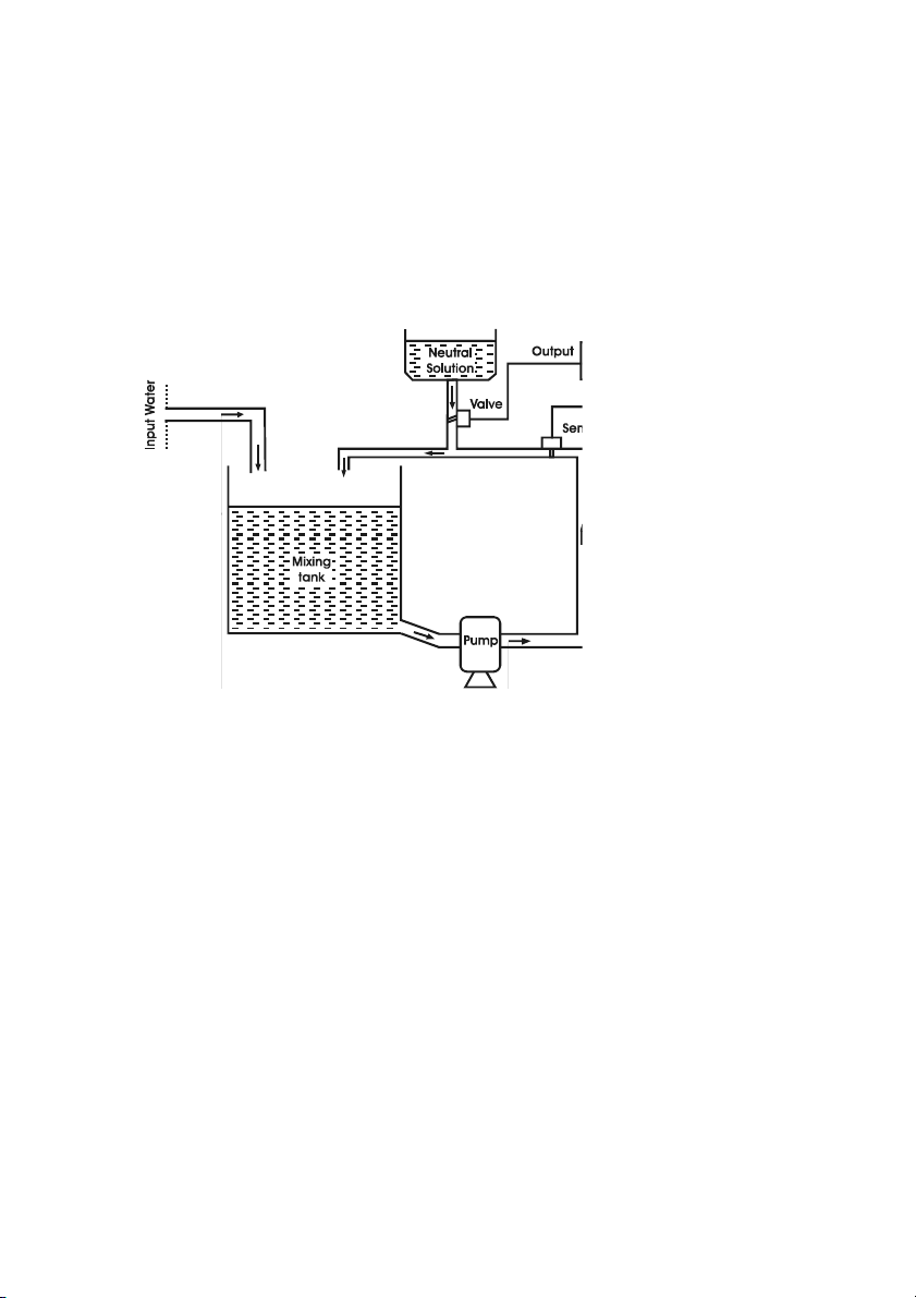
3.5 PID CONTROL
A simplified schematic of the control (pH and EC):
EC and pH control is performed using an automatic regulated system with PID
controller (Proportional, Integral and Derivative). The role of this controller is to
maintain a set pH and EC value within a mixing tank prior and during distribution (see diagram). The control of pH and EC is made separately.
The components are as follows:
- The mixing tank where the influent and additives are combined
- The neutral (additive) solution tank containing an acid, base or fertilizer
- The valve for introducing the additive solution into the mixing tank con-
trolled by the PID controller
- PID Controller
- The input (influent) water source
- The pump for pumping water from the tank to the irrigation sectors
The Fertigation Controller automatically provides a command output signal to a
control element such as a pump or valve based on a sensor input signal. The
function of the Fertigation Controller is to proportionally control the pH and EC
of the process at a specified set point. The above output signal commands the
11
Page 12
12
Page 13

opening and closing of a valve through which a neutral solution is circulated.
The amount of neutral solution added is relative to the opening of the valve,
which is directly proportional to the magnitude of difference between the mixing
tank pH and the set point.
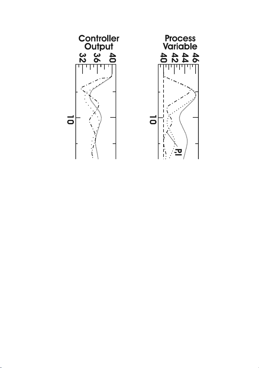
Control of pH implies a complex adjustment. The relation between the added
reagent and the process pH is logarithmic. There is the possibility to introduce
large errors in the process due to over dosing or under dosing reagent creating
an oscillation effect. PID control can be used to reduce the possibility of overshoot and large oscillations in the process by creating control output proportional to the magnitude of deviation from the set point (P), time integral of error
(I), and rate of change of the measurement (D). Proportional, Integral, and
Derivative (PID) control can be used individually (typically Proportional control
only) or in combination such as PI, PD or PID. How these control actions are
used depends upon the requirements of the process.
Set point (reference value) is the desired value of the measurement. The error is
defined as the difference between the set point and measurement:
Error = Setpoint – Measurement
The descriptions and definitions of the individual control actions are as follows:
PROPORTIONAL ACTION (P):
The simplest continuous control mode is proportional control, so called because
the controller output is proportional to the magnitude of error. However, the
proportional control is subject to one major limitation, steady state offset (steady
deviation from the set point). Increasing the sensitivity of the controller (controller gain) can reduce the steady state offset but only with slow processes. For this
reason the proportional control by itself it is used primarily for slow, consistent
processes that can tolerate high controller gain, which minimizes the steady state
offset. Consequently, high gain control action can throw the process into oscillation if the process variable becomes unstable and begins to change rapidly.
INTEGRAL ACTION (I):
To eliminate offset droop and tighten the control of the process, the integral
action is introduced in conjunction with proportional control (PI). Integral control produces control action proportional to the time integral of the error. As
long as the error exists (steady deviation from the set point), the integral term will
continue to increase, adding more control action, driving the error toward zero.
DERIVATIVE ACTION (D):
With derivative action, the controller output is proportional to the rate of change
of the measurement and is primarily used to avoid overshoots. Derivative action
13
Page 14

can compensate for changes in the process variable (measurement) and is particularly good for slowly moving processes. When a change occurs in the process the derivative action causes the controller gain to move the “wrong” way
until the measurement gets near the set point.
3.6 AGITATOR CONTROL
Each of the 4 fertilizer tanks may have an agitator.
An agitator can be activated in a specific tank prior to tank selection by an
irrigation program. The pre-agitation time can be set using panel S 45 (SET
AGITATORS); the pre-agitation occurs only when the pre-irrigation time is set.
During the irrigation program, the agitators can be stopped (if working time is
zero), set to work continuously (if pause time is zero) and intermittently (if working
time and pause is different than zero).
The work and pause time can be set using panel S 45 (SET AGITATORS).
The agitator settings are displayed on panel C 17 (AGITATOR STATE).
3.7 FILTER CONTROL
Fertigation Controller has the capability to check and automatically clean two
filters controlled by two filter-cleaning programs.
Each filter cleaning program can be started by the following conditions:
- Following one specified irrigation program. This irrigation program can
be set in panel S 46 (FILTERS CTRL).
- When a “dirty filter” alarm is activated. Cleaning by this option is set using
panel S 46 (FILTERS CTRL).
- The working time for filter-cleaning programs can be set using panel S 46
(FILTERS CTRL).
3.8 MANUAL FUNCTIONS
The Fertigation Controller has the following Manual function capabilities:
- To switch the controller state between STOP, WORK and INIT, use panel S
49 (CONTROLLER STATE).
- The controller state can be checked using panel C 01 (GENERAL INFO).
- To manually start a program use panel S 47 (PROG MAN START).
- To manually stop a program use panel S 48 (PROG MAN STOP).
- To check and to change the value for each of the outputs, use panel S 50
(OUTLET MAN CTRL).
14
Page 15

- To erase all statistics, use panel S 61 (ERASE STATISTICS). Statistics indicates pH and conductivity averages for all irrigation programs and sectors
in addition to average total irrigation accumulation.
- To erase the settings of one irrigation program or to erase all settings for all
irrigation programs, use panel S 62 (ERASE SETTINGS).
3.9 ALARMS
The Fertigation Controller has the capability to supervise and generate an alarm
for the following conditions:
- Conductivity sensor out of range. Reference, minimal and maximal offset
and threshold for conductivity alarm are set using panel S 41 (COND
CONTROL). The current values of conductivity sensors are displayed on
panel C 05 (EC STATE)
- A difference greater than the set value between the first and second conductivity sensors; Maximum value of difference is set using panel S 55
(SENSORS CONFIG)
- pH sensor out of range. The reference, minimum and maximum offset and
threshold for pH alarm are set using panel S 40 (PH CONTROL). The
current values of pH sensors are displayed on panel C 04 (pH STATE)
- A difference greater than the set value between pH sensors; the maximum
difference value is set using panel S 55 (SENSORS CONFIG)
- Problems with the water supply
- Dirty filters
When the level is low in the fertilizer and acid tanks the system will take appropriate action and record the alarm. These actions can be:
- in case of a pH alarm condition, the irrigation process can be suspended
or continued depending on the choice set within panel S 52 (ALARM
BEHAVIOR) depending on the choice set within.
- in case of an EC alarm condition, the irrigation process can be suspended
or continued depending on the choice set within panel S 52 (ALARM
BEHAVIOR) depending on the choice set within.
- in case of a dirty filter alarm condition, start the filter cleaning program in
accordance with the priority and working time settings
- in case of a water supply alarm situation, the Controller will stop every
irrigation process until the alarm is shot off.
All alarm situations are displayed on panel C 25 (ALARM).
All anomalies (old alarm conditions) are displayed on panel C 27 (ANOMALY).
15
Page 16

3.10 LOGGING FUNCTIONS
The Fertigation Controller has the capability to log the most important occurred
events and values of different parameters that can offer a description of the
evolution of the entire process;
The most important values are:
- Number and time period of every program activation;
- Filter cleaning;
- Averages of pH and conductivity;
- Accumulations;
- Modifications to preset fertilization values (e.g. manual, solar radiation);
- Alarms;
The logging level for recording and consulting can be set using panel S 59 (SET
LOG LEVELS).
The date of desired logging records can be set using panel C 26 (VIEW LOG
DATE).
The logging records are displayed on panel C 28 (LOG).
The selectable log recording/consulting levels range from 1 to 3. They are as-
signed as it follows:
Level 1: - records the sensors deviations events
Level 2: - records statistics (pH and EC averages, accumulations)
Level 3: - records programs and controller status events.
3.11 DATE AND TIME CONTROLLER SETTINGS
The controller date and time can be checked on panel C 01 (GENERAL INFO)
and can be set using panel S 30 (SET DATE & TIME).
3.12 PASSWORD SETUP
The access to Fertigation Controller can be protected by a password. This password can be set using panel S 60 (SET PASSWORD), also this password can be
disabled using the same panel.
16
Page 17
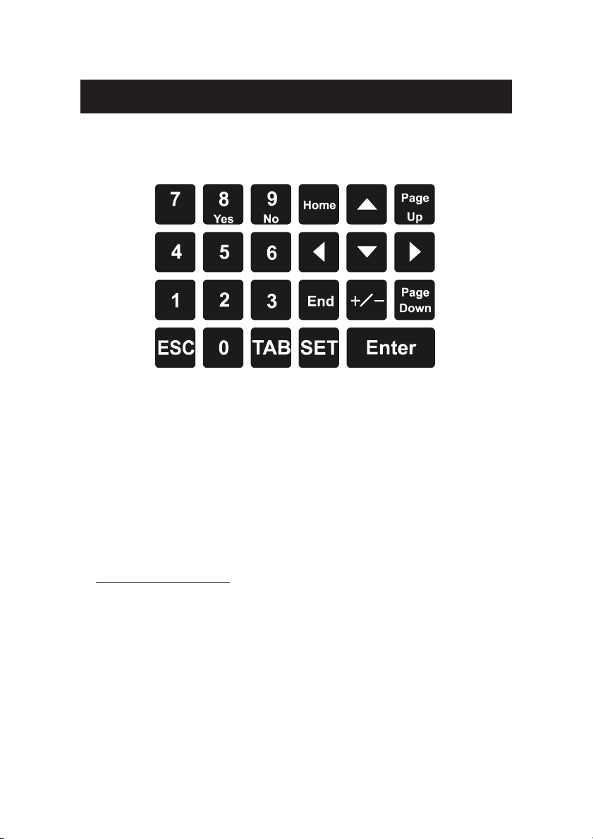
4 USER INTERFACE
The Fertigation Controller’s user interface consists of a 4 x 20 character LCD
and a 23-key keyboard.
Keyboard structure.
4.1 OPERATING MODES
The Fertigation Controller operates primarily in two major modes:
Consulting Mode Setting Mode
User interface panels (screens) are broken down into two categories:
1. CONSULTING PANELS
2. SETTING PANELS
Both modes of operation are readily available to the user.
1. CONSULTING MODE
The consulting mode allows the user to view the current state and set the conditions of the Fertigation Controller. The setting panels are in consulting mode
until the SET key is pressed. The primary consulting screens are designated from
C 01 through C 29. The following outline highlights the functions of the consulting mode.
- 2 browsing methods are enabled. See Section 4.2 “PANEL BROWSING
METHODS”.
- UP and DOWN ARROWS KEYS can be used to switch the panel index
(where available) allowing user to view the same kind of data assigned to
17
Page 18

different controller entities (programs, sectors, fertilizers etc.) within the same
panel.
- LEFT and RIGHT ARROWS KEYS can be used to move the cursor within
the selected parameter’s limits.
- ESC key can be used as a shortcut key to access the C 03 (PROGRAM
STATE) panel from any currently viewed panel.
- HOME key can be used as a shortcut key to access the C 01 (GENERAL
INFO) panel from any currently viewed panel.
- END key can be used as a shortcut key to access the S 48 (PROG MAN
STOP) panel from any currently viewed panel.
- TAB key can be used to switch the focus between the panel number object
and the panels index parameter if the current panel is indexed. If there is no
index parameter present on the current panel, the TAB key has no effect.
Panels are typically indexed by the program number. For example, panel
C 03 (PROGRAM STATE) displays the current state for each program.
Once panel C 03 is selected and the TAB key pressed, the focus (cursor) is
shifted from the panel number to the program number “Prog 01”. The
ARROW KEYS can now be used to scroll through each program state
consecutively without leaving the panel.
- ENTER key is used to confirm any new values entered in any of the selected
panels. This is only possible if data items on a panel (screen) are selectable.
2. SETTING MODE
The setting mode allows configuration of all the adjustable parameters of the
Fertigation Controller. The setting screens are designated from S 30 to S 62.
These panels can be viewed by one of 2 browsing methods. Selecting the appropriate screen and pressing the SET key initiates the setting mode. Once the
setting mode is entered both panel-browsing methods are disabled and navigation is allowed only within the currently selected panel. The following outline
highlights the functions of the Setting Mode.
- Both panel (screen) browsing methods are disabled. See Section 4.2 “PANEL
BROWSING METHODS”.
- Focus (cursor location) is automatically shifted to the first editable data
object on the selected panel.
- UP, DOWN arrow keys allow navigation between all editable data objects
within the current panel.
18
Page 19

- LEFT, RIGHT arrow keys allow navigation within the currently focused
data object. If the cursor exceeds the boundaries of the data object then the
focus is transferred to the previous or next editable item within the current
panel.
- TAB key can be used to move only in a forward direction, from one data
object to the next within the selected panel.
- ENTER key confirms all the data entered in a current panel. Once the
ENTER key is pressed and data confirmed, the controller reverts to consult-
ing mode. The SET key must be pressed to reenter the setting mode.
- ESC key cancels new data entered in the currently focused data object
and exits the setting mode. The change of data is not saved in the current
object and the previous setting is maintained.
19
Page 20
4.2 PANEL BROWSING METHODS
In consulting mode, two browsing methods are available to view each of the 62
panels (screens) of the Fertigation Controller.
- Step-by-step browsing: pressing the PAGE UP and PAGE DOWN keys
allow consecutive navigation from one panel to the next. The direction is
dependent upon which key is selected.
- Direct access browsing: the number of the desired panel can be entered
directly using the panel number located on the bottom right corner of every
panel, prefixed by a C or S. The panel number object is the initially focused
object on each screen. After entering the value by using the keypad and
ARROW KEYS, press the ENTER key to view the selected panel.
NOTE: If a panel is selected and the SET key is pressed entering the setting
mode, both browsing methods are disabled.
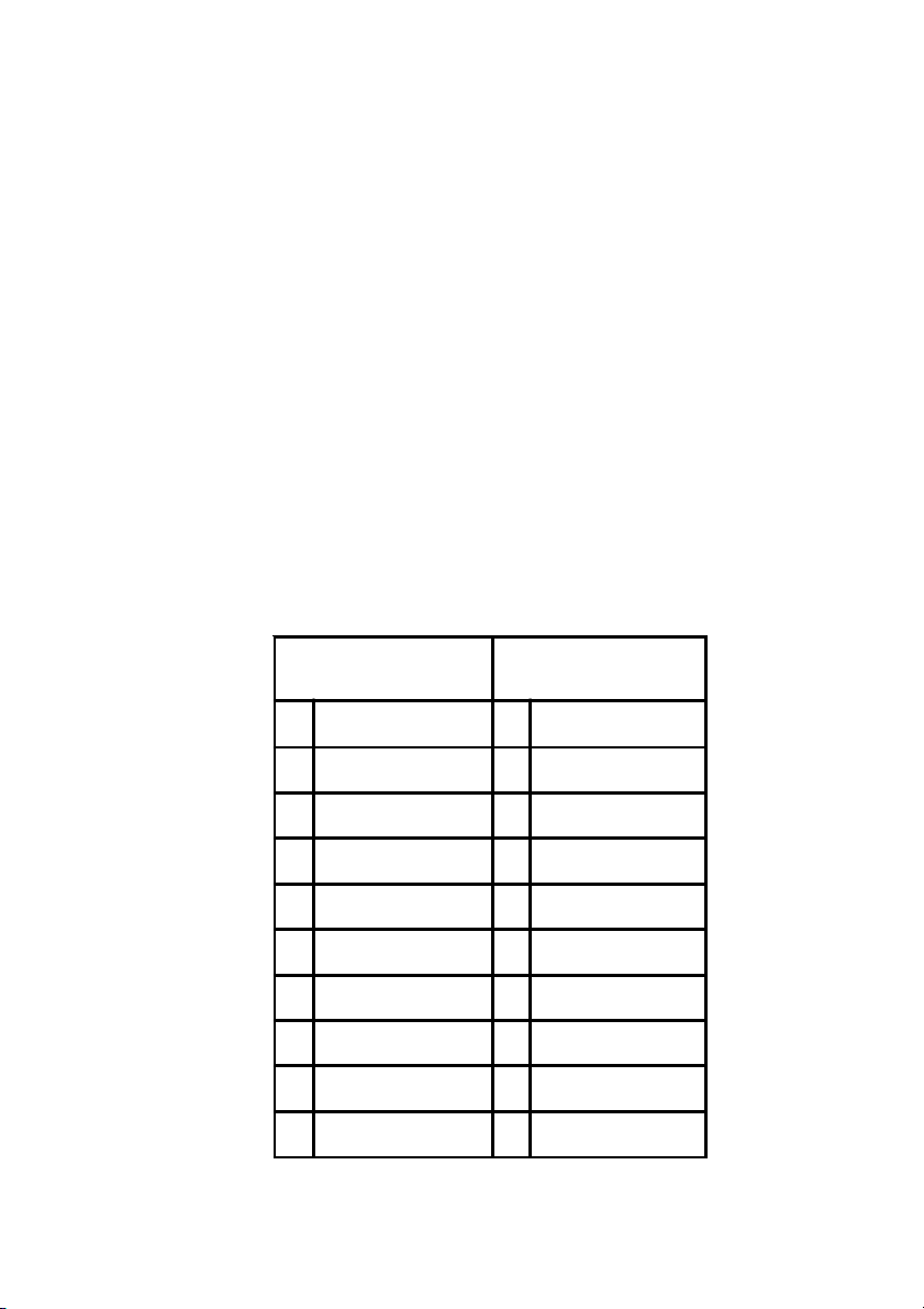
4.3 PANEL LIST
PANEL TABLE
CONSULTING PANELS SETTING PANELS
01 GENERAL INFO 30 SET DATE & TIME
02 SENSORS STATE 31 ACTIVE TIMETABLE
03 PROGRAM STATE 32 WORKDAY
04 PH STATE 33 SET PRIORITY
05 EC STATE 34 START CONDITION
06 SOLAR RAD IRRIG 35 SET START TIME
07 - 36 PROGRAM REPEATS
08 WORK TIME COND 37 PRE / POST IRRIG
09 PRIOR & CONFL ICTS 38 SET SE CTORS
10 IRRIG STATE 39 SET FERTILIZERS
20
Page 21
11 SOL RAD EXTENS 40 PH CONTROL
12 MAN CORRECTION 41 COND CONTROL
13 TOTAL CORRECTION 42 CORRECTIONS
14 SECTOR STATE 43 SOLAR RAD IRRIG
15 - 44 -
16 FERTILIZ STATE 45 SET AGITATORS
17 AGITATOR STATE 46 FIL TERS CTRL
18 PROG LAST START 47 PROG MAN START
19 TOTAL ACCUMUL 48 PROG MAN STOP
20 PROGRAM ACCUMUL 49 CONTROLLER STATE
21 S ECTOR A CCUMUL 50 OUTL ET MAN CTRL
22 TOTAL AVERAGES 51 PH CTRL OPTIONS
23 PROGRAM AVERAGES 52 ALARM BEHAVIOR
24 SECTOR AVERAGES 53 IRRIG CTRL MODE
25 ALARM 54 CALIBRATE SENSOR
26 VIEW LOG DATE 55 SENSORS CONFIG
NOTE: Data that has been changed in an editable data object is saved once
focus has been removed from that object by pressing the ARROW KEYS
or TAB .
21
Page 22
5 PANEL DESCRIPTION
5.1 GENERAL CONSULTING
The following panels C 01 through C 29 are for the general consulting of
controller settings and current measurements. The data objects within each
panel are described from left to right unless otherwise specified.
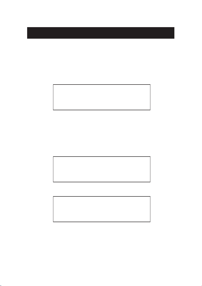
5.1.1 INITIALIZATION PANEL
HANNA INSTRUMENTS
F1 CONTROLLER V0.90
INITIALIZATION
Loading String Table
This panel is shown during the Fertigation Controller Initialization state; it contains the HANNA INSTRUMENTS logo, the name of the controller and the
software version. The last line is used to display the current status of the initialization sequence. This panel is also used to display any possible errors that may
occur during the start up sequence.
5.1.2 START PANEL
HANNA INSTRUMENTS
F1 CONTROLLER
Fri 15-03-2000 13:15
STOP Press ENTER
5.1.3 INPUT PASSWORD PANEL
Enter password
****
This panel is displayed during the password authentication sequence. If this
sequence fails, the user will be logged out and the START panel will be displayed.
If the password is correct panel C 01 (GENERAL INFO) is displayed. The default password is 0000. See section 6.9.10 (Setting Password, S 60) for instructions on setting this feature.
22
Page 23

Although access to the controllers features are denied, the functionality of the
controller is not directly effected if a password authentication sequence fails.
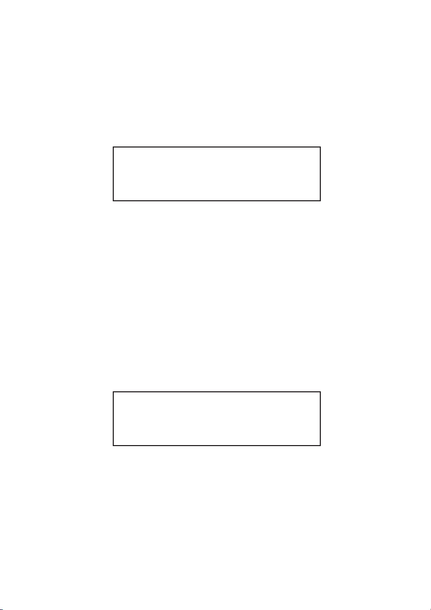
5.1.4 GENERAL INFO – C 01
WORK Anomalies 00
Prog 08 06.4pH
Sect 07 02.1mS 13:15
GENERAL INFO C01
This panel displays the following information starting from top left:
Fertigation Controller Functional State (top left corner)
When the controller is running it can be in one of the following states:
INITIALIZATION, STOP, WORK, BLOCK. When the Fertigation Controller is
first powered on the first state is INITIALIZATION. In this state the unit
performs internal tests. In STOP state all programs are suspended. Under
normal conditions the functional state is WORK. In the WORK state all
irrigation and fertilization programs are executed. If an alarm occurs the
Fertigation Controller enters the BLOCK state until the alarm condition is
corrected. The user can customize the alarm management system behavior
using setting panels S 40, S 41 (pH and EC CONTROL) and panel S 52
(ALARM BEHAVIOR).
Anomalies (top right corner)
The anomalies counter represents the number of alarms triggered since
the last reset of the counter. This counter can be customized and cleared
along with all system statistics via setting panel S 61 (ERASE STATISTICS).
Program Number
Reflects the selected program (can be selected only inside panel C 03). If
no program is active a number is not visible.
pH sensor reading
Current (main) pH sensor reading.
Sector Numbers
All sectors assigned to the active program are displayed (cyclically) but
only when an active program is running. If a program is not active the
number is not visible.
EC sensor reading
Current (main) EC sensor reading.
System clock
If an alarm condition is present the time indication will also flash “ALARM”
to alert the user.
23
Page 24

NOTE:
- If the user is logged in and the operational mode is CONSULTING MODE,
this panel can be accessed anytime and from any panel using the HOME key
as a shortcut.
- The Real Time Clock, pH and EC sensors are always visible regardless of
state.
- Whenever the Fertigation Controller is connected to a PC that runs the specific
application of the fertigation controller on PC in “ON LINE” mode, this
panel displays the label “PCCom” above the controller clock position. In this
case the Fertigation Controller’s keyboard is disabled until the connection is
lost due to different reasons.
5.1.5 SENSORS STATE – C 02
Active Program: 04
06.3pH 1200W/m2
06.4mS 13:15
SENSORS STATE C02
This panel provides an overview of the real time values of the system’s main
sensors. This panel contains the following information:
Active program number
Displays the number of the executing program. If no program is running a
number is not displayed.
pH sensor reading
Solar Radiation sensor reading
EC sensor reading
System clock
5.2 CONSULTING PROGRAM SETTINGS
The following panels allow viewing the program setting of the Fertigation Controller. The program number can be changed only in C 03 with the UP and
DOWN keys. In addition, the TAB key can be used only in C 03 to toggle the
cursor (focus) between the panel number and the program number. The desired
program number can then be entered directly by using the keypad.
24
Page 25

5.2.1 PROGRAM STATE – C 03
PROG 08 ACTIVE
Started by Solar Rad
Repeat 02/05 13:15
PROGRAM STATE C03
The purpose of this panel is to allow the user to inspect the status and settings of
a particular program. The program number indexes this panel. This panel contains the following information:
Program Number
Reflects the selected program (can be selected only inside panel C 03). See
Section 5.2.
Program State
During the lifetime of a program it cycles through several states. Each
program is initially in NO SET state which means no settings have been
applied to the program by the user. Once the settings have been applied
the program is considered in SET state. Once a specific condition such as
start time is met the program passes to READY state to await execution.
Once the program reaches the highest priority and the start time is met, the
program passes to ACTIVE state and executes. The program may be suspended and placed in WAIT state due to a higher priority program moving
to ACTIVE state or a specific alarm condition triggering. When a program
completes execution it is placed in FINISHED state. The cycle may be
repeated and the program returned to ready state if the program repeats
were specified after a set delay period.
Program Started by
Displays how the last program start was triggered. Programs can be started
by a met time condition, solar radiation level, manual start, low level in
external tank, or directly after the completion of another program. If the
program is in NO SET (no settings applied to program) or in SET (settings
applied but conditions not met) state, “Started by” is blank.
Repeat
Displays the current repetition followed by (/) the maximum number of the
programmed repetitions.
System clock
25
Page 26

REMINDER: In CONSULTING MODE the ESC key can be used as a short-
cut key to access this panel from any panel.
5.2.2 PH STATE – C 04
Prog 08 Ref=06.4pH
S1=05.4PH
S2=05.5PH 13:15
PH STATE C04
The purpose of this panel is to allow the user to inspect the current pH reference
point for a specific program and the real time pH sensor readings. The program
number indexes this panel. This panel contains the following information:
Program Number
Reflects the selected program (can be selected only inside panel C 03).
See Section 5.2.
Ref = Reference or set point pH value for the specified program.
S1 = Real time value of pH sensor 1. This reading applies to the entire process
and is not program specific.
S2 = Real time value of pH sensor 2. This reading applies to the entire process
and is not program specific.
System clock
5.2.3 EC STATE – C 05
Prog 08 Ref=02.0mS
S1=02.0mS SIn=03.2mS
S2=02.1mS 13:15
EC STATE C05
The purpose of this panel is to allow the user to inspect the current EC reference
point for a specific program and the real time EC sensor readings. The program
number indexes this panel. This panel contains the following information:
Program Number
Reflects the selected program (can be selected only inside panel C 03).
See Section 5.2.
Ref = Reference or set point EC value for the specified program.
S1 = Real time value of EC sensor 1. This reading applies to the entire process
and is not program specific.
S2 = Real time value of EC sensor 2. This reading applies to the entire process
26
Page 27
and is not program specific.
S in = Real time value of EC input sensor. This is an option sensor input to
measure the conductivity of the incoming water supply. This reading applies to
the entire process and is not program specific.
System clock
5.2.4 SOLAR RAD IRRIG – C 06
Prog 08
Irrig=0720Wh/m2
Acc=0720Wh/m2 13:15
SOLAR RAD IRRIG C06
This panel displays the solar radiation irrigation settings. Due to the effects of
solar radiation it may be necessary to augment (correct) the irrigation process
accordingly. The program number indexes this panel. This panel contains the
following information:
Program Number
Reflects the selected program (can be selected only inside panel C 03). See
Section 5.2.
Irrig = The set level of accumulated solar radiation used for irrigation correction. This is a set point. Radiation beyond this limit will trigger a correction to the
irrigation process.
Acc = Real time value of accumulated solar radiation.
System clock
5.2.5 WORK TIME COND – C 08
Prog 08 Time Y
Day Y
Period Y 13:15
WORK TIME COND C08
The program number indexes this panel. This panel contains the following information:
Program Number
Reflects the selected program (can be selected only inside panel C 03). See
Section 5.2.
Time
Indicates if the selected program is set to run on a time schedule.
27
Page 28

Day
Indicates if the selected program is set to run on a daily schedule.
Period
Indicates if the selected program is set to run on a yearly schedule.
System clock
5.2.6 PRIOR & CONFLICTS – C 09
Prog 08 Priority 05
Conflict Programs 02
13:15
PRIOR & CONFLICTS C09
This panel indicates the priority level of the indexed program. Priority settings
play a roll in program execution when two or more programs have similar starting conditions. The priority for a given program can be set using panel S 33
(SET PRIORITY). The Conflict Programs counter displays cyclically all programs
that are in conflict with the currently active program. Programs can be in conflict
if their specific start and running conditions are synchronous. Given this scenario, the program that has the highest priority will become active.
The program number indexes this panel. This panel contains the following information:
Program Number
Reflects the selected program (can be selected only inside panel C 03).
See Section 5.2.
Priority
Displays priority of indexed program.
Conflict Programs
Cyclically displays the program number of programs in conflict with the
currently active program.
System clock
5.2.7 IRRIG STATE – C 10
Prog 08 IRRIG
Set 01:15:20+005:55
Done 00:45:10 13:15
IRRIG STATE C10
28
Page 29

This panel displays the current irrigation state of the indexed program. Time or
volume can control irrigation and the above panel displays the set value and the
amount of irrigation currently completed. The mode of irrigation (time or volume) can be selected using panel S 53 (IRRIG CTRL MODE). The program
number indexes this panel. This panel contains the following information:
Program Number
Reflects the selected program (can be selected only inside panel C 03).
See Section 5.2.
Set
Displays the required (set) value of irrigation in time or volume.
Irrigation correction value
(number directly following the Set value)
Done
Displays the current point of irrigation in time or volume.
System clock
5.2.8 SOL RAD EXTENT – C 11
Prog 08
+010%
+00:05:55 13:15
SOL RAD EXTENT C11
This panel displays how much the programmed irrigation parameters are modified (extended) due to the effects of solar radiation. The program number indexes
this panel. This panel contains the following information:
Program Number
Reflects the selected program (can be selected only inside panel C 03).
See Section 5.2.
Irrigation extension percentage
Displays the overall extension percentage of irrigation for the selected program due to solar radiation.
Irrigation extension value
Displays (in time or volume) the extension value of irrigation for the selected program due to solar radiation.
System clock
29
Page 30

5.2.9 MAN CORRECTION – C 12
Prog 08
+015%
+00:05:55 13:15
MAN CORRECTION C12
This panel displays how much the programmed irrigation parameters are manually modified (corrected). The program number indexes this panel. This panel
contains the following information:
Program Number
Reflects the selected program (can be selected only inside panel C 03). See
Section 5.2.
Irrigation extension percentage
Displays the overall extension percentage of irrigation for the selected program due to manual correction.
Irrigation extension value
Displays (in time or volume) the extension value of irrigation for the selected program due to manual correction.
System clock
5.2.10 TOTAL CORRECTION – C 13
Prog 08
+035%
+12:00:13 13:15
TOTAL CORRECTION C13
This panel displays how much the programmed irrigation parameters are modified due to both manual and solar radiation corrections. The program number
indexes this panel. This panel contains the following information:
Program Number
Reflects the selected program (can be selected only inside panel C 03). See
Section 5.2.
Irrigation extension percentage
Displays the overall extension percentage for a selected program.
Irrigation extension value
Displays (time or volume) the total extension value of irrigation for the
selected program.
System clock
30
Page 31

5.2.11 SECTOR STATE – C 14
Prog 08 Sect 21/21
Set 00:10:30+009:45
Done 00:03:10 13:15
SECTOR STATE C14
This panel displays the state of each sector. Each sector has an electro-valve.
When a particular sector requires irrigation the electro-valve is opened for a
specified period of time. Valve number along with sector label (upper right
corner of display) indexes this panel. This panel contains the following information:
Program Number
Reflects the selected program (can be selected only inside panel C 03). See
Section 5.2.
Sect
The first number displayed is the sector number followed by “/” the valve
number assigned to that sector. This parameter indexes the sectors for this
panel.
Set
Displays the set value in time or volume for the selected sector/valve of the
indicated program.
Done
Displays the current point of irrigation in time or volume for the selected
sector/valve of the indicated program.
System clock
NOTE: The sector’s label can be assigned as customized numeric “tags” for all
the Fertigation Controller’s valves. Labels can be specified using panel
S 38 (SET SECTORS). As default, the sector label will be identical to the
corresponding valve number.
5.2.12 FERTILIZ STATE – C 16
Prog 02 Fert 02
Set 40%
Current 20% 13:15
FERTILIZ STATE C16
31
Page 32

This panel displays the set and current amount of fertilizer used for a specific
program. The Fertigation Controller controls the dosing of 4 fertilizers. In this
panel the fertilizer number is used as the index, allowing inspection of the percent values for up to four fertilizer tanks involved in the selected irrigation program. This panel contains the following information:
Program Number
Reflects the selected program (can be selected only inside panel C 03). See
Section 5.2.
Fert
Represents the index for this panel. Fertilizer tank number. Each program
can control 1 to 4 fertilizer tanks.
Set
The set percentage of one of four selected fertilizers to be dosed.
Current
The current consumed percentage of one of four selected fertilizers.
System clock
NOTE: The fertilizers percentage values can be specified using S 39 (SET FER-
TILIZERS).
5.2.13 AGITATOR STATE – C 17
Prog 08
Work 00:03 WORK
Pause 00:02 13:15
AGITATOR STATE C17
To each of the 4 fertilizer tanks an agitator can be assigned . The agitators can
be activated before dosing of a fertilizer, during dosing, or intermittently throughout the program. See Section 3.6 AGITATOR CONTROL for more information.
In this panel the agitator number is used as the index. This panel contains the
following information:
Program Number
Reflects the selected program (can be selected only inside panel C 03). See
Section 5.2.
Work
The set working time value for the indexed agitator of the selected pro-
gram.
32
Page 33

Pause
The set pause time value for the indexed agitator of the selected program.
System clock
NOTE: The agitator’s working time values can be specified using panel S 45
(SET AGITATORS).
5.2.14 PROG LAST START – C 18
Prog 08 Filter -Last start Manual
At 28-08 18:32 13:15
PROG LAST START C18
This panel displays the last start data for the indexed program, including the
filter-cleaning programs. There are 2 filter-cleaning programs, one for each
filter. The filter programs follow the indexed irrigation programs. For example, if
the Fertigation Controller is equipped with 10 irrigation programs, “Prog” number 11 and 12 will be designated for the two filter cleaning programs on the
above panel. In this case the first 10 program numbers will indicate the last start
data for the irrigation process. Programs 11 and 12 will indicate the last start
data for filter cleaning. The program number indexes this panel. This panel
contains the following information:
Program Number
Reflects the selected program (can be selected only inside panel C 03).
See Section 5.2.
Filter
Filter number
Last Start
The last start trigger for the indexed program (irrigation or filter cleaning).
At
The time of the last start for the indexed program.
System clock
33
Page 34

5.3 STATISTICS CONSULTING
5.3.1 TOTAL ACCUMUL – C 19
From: 09-26 13:37;12
0007654L
13:15
TOTAL ACCUMUL C19
This panel provides a total (in time or volume) of the entire irrigation process (all
programs) from the reset time. All Fertigation Controller’s statistics including
accumulations can be erased (manually, daily at specified hour, on overflow )
within panel S 61 (ERASE STATISTICS).
This panel contains the following information:
From
Time stamp indicating the beginning of the overall irrigation process.
Accumulation
Total accumulation in time or volume
System clock
5.3.2 PROGRAM ACCUMUL – C 20
From: 09-26 13:37;12
000:00:25 Prog 01
Activations 03 13:15
PROGRAM ACCUMUL C20
This panel provides a total (in time or volume) for each of the irrigation programs. The program number indexes this panel. This panel contains the following information:
From
Time stamp indicating the start of recording (statistics).
Accumulation
Total accumulation in time or volume for the indexed program.
Program Number
Reflects the selected program (can be selected only inside panel C 03). See
Section 5.2.
Activations
The number of activations of the indexed program since the recording start.
System clock
34
Page 35

5.3.3 SECTOR ACCUMUL – C 21
From: 09-26 13:37;12
000:00:17 Sect 01/01
13:15
SECTOR ACCUMUL C21
This panel provides a total (in time or volume) for each of the irrigation sectors.
The valve number indexes this panel. This panel contains the following information:
From
Time stamp indicating the start of recording (statistics).
Accumulation
Total accumulation in time or volume for the indexed valve.
Sect
The sector number (label) / valve number (index for this panel).
System clock
5.3.4 TOTAL AVERAGES – C 22
From: 09-26 13:37;12
05.3pH
06.7mS 13:15
TOTAL AVERAGES C22
This panel indicates the overall average of pH and conductivity for the entire
irrigation process. This panel contains the following information:
From
Time stamp indicating the start of recording (statistics).
pH
The pH total average.
mS
The EC total average.
System clock
35
Page 36

5.3.5 PROGRAM AVERAGES – C 23
From: 09-26 13:37;12
05.3pH Prog 01
06.7mS 13:15
PROGRAM AVERAGES C23
This panel provides a pH & EC average for each of the irrigation programs. The
program number indexes this panel. This panel contains the following information:
From
Time stamp indicating the start of recording (statistics).
pH
The pH average for the indexed program.
Program Number
Reflects the selected program (can be selected only inside panel C 03). See
Section 5.2.
mS
The EC average for the indexed program.
System clock
5.3.6 SECTOR AVERAGES – C 24
From: 09-26 13:37;12
05.3pH Sect 01/01
06.7mS 13:15
SECTOR AVERAGES C24
This panel provides an average pH and EC reading for each of the irrigation
sectors. The valve number indexes this panel. This panel contains the following
information:
From
Time stamp indicating the start of recording (statistics).
pH
The average pH reading for the indexed valve.
Sect
The sector number (label) / valve number (index for this panel).
mS
The average EC reading for the indexed valve.
System clock
36
Page 37

5.4 ALARMS CONSULTING
5.4.1 ACTIVE ALARMS – C 25
Low level fert: 4
ACTIVE Alarm
26-12 14:36:22 13:15
ALARM 02/07 C25
This displays the active alarms current in the system. Once viewing the panel all
of the alarms can be scrolled and viewed using the UP and DOWN or ENTER
keys. This panel contains the following information:
Alarm Description
Time of alarm occurrence.
Alarm
The alarm number and (/) total number of all active alarms.
System clock
When at least one active alarm is present, the system clock blinks “ALARM”.
This indication is displayed on all panels having the system clock.
NOTE: The alarm management system is designed to provide self-update
behavior, thereby no user intervention is required to restore the status of
the interrupted program once the condition is resolved. If the condition
of the active alarms change, the panel will reflect the change accordingly without user intervention.
5.5 LOG CONSULTING
5.5.1 VIEW LOG DATE – C 26
Log consulting date:
26-12
15:05
VIEW LOG DATE C26
This panel allows the user to view log data from a specific date. The SET key is
used to enter the date of choice thus entering the setting mode. After entering the
panel and pressing the SET key, the cursor (focus) is shifted from the panel
number to the first place of the day indicator. The key pad and arrow keys can be
used to enter the selected date followed by the ENTER key. Once ENTER is
37
Page 38

pressed the Fertigation Controller will search for the logged data. If no data is
found the panel is shifted to C 28 (LOG) and “no records found” is displayed.
This panel contains the following information:
Log consulting date
The initial viewing date set by the user.
System clock
5.5.2 ANOMALIES (ALARMS HISTORY) – C 27
Low level fert: 4
CLEARED ALARM
26-12 14:36:22 13:15
ANOMALY 0193/22 C27
This screen displays anomalies. Anomalies are considered alarm history. This
screen displays alarm conditions that are no longer active. Once viewing the
panel all of the anomalies (prior alarms) can be scrolled and viewed using the
UP and DOWN or ENTER keys.
This panel contains the following information:
Alarm Description
Cleared Alarm indication
Time stamp
Time of alarm occurrence.
System clock
ANOMALY
The anomaly log record number and “/” the number of all anomalies since
the system statistics were recorded.
The anomalies log record number can be erased on panel C 61 erasing
the statistics.
5.5.3 LOG – C 28
Ext state: ACTIVE
Prog State changed.
18-08 15:05:30 15:05
Log 0012 Lev 03 C28
The Fertigation Controller log system is a three level hierarchically designed,
which means that the events are classified in three selectable categories. The
consulting log level displayed in this panel can be changed directly using the
38
Page 39

SET key or via panel S 59 (SET LOG LEVELS). The UP and DOWN arrow keys
are available to move between log records in a “select previous/next” manner.
This panel displays the following information:
Log record
Log record description.
Time stamp
Time stamp of logged occurrence.
Log record number
Log consulting level
System clock
5.6 GENERAL SETTINGS
The Setting panels provide an interface by which the user can set up the functionality of the Fertigation Controller to suite the application requirements. The
parameters in any setting panel can be modified only if the user presses the SET
key (entering the setting mode). Once pressing the SET key the cursor (focus) is
passed to the first adjustable parameter on the panel. Using the keypad along
with the arrow keys the user can set the desired parameters and navigate within
the panel. The ENTER key validates all entries. In SET MODE panel the browsing methods are disabled until the user exits from SET MODE by pressing the
ENTER (validation) or ESC (cancel) key.
To change program number you must go to panel C 03 and then continue.
5.6.1 SET DATE & TIME – S 30
Date: Fri-22-09-2000
Time: 17:03:20
17:03
SET DATE & TIME S30
This panel allows the setting of the following parameters:
Date
Day / Month / Year format. The day is automatically updated once the
numeric date is entered and confirmed.
Time
Hour / Minute / Seconds format. The time is automatically updated once
the numeric time is entered.
System clock
39
Page 40

5.7 PROGRAM SETTINGS
5.7.1 ACTIVE TIMETABLE – S 31
Between Prog 07
Date: 01-04 31-10
Time: 07:00 23:00
ACTIVE TIMETABLE S31
This panel allows the user to set the scheduled limits for the indexed program.
The program number indexes this panel (For more details see Section 3.1 and
Appendix 3). This panel allows the setting of the following parameters:
Program Number
Reflects the selected program (can be selected only inside panel C 03). See
Section 5.2.
Date
The yearly schedule limits for the selected program.
This sets the limit of program operation between day / month and day /
month.
Time
The daily schedule limits the selected program. This sets the limit of program operation hour:min to hour:min.
5.7.2 WORKDAYS – S 32
Work day 02 Prog 07
Rest day 03
Weekday SMTWTFS
WORKDAY NNNNNNN S32
This panel allows the user to set a workday scheduled for the indexed program.
Once the yearly and daily limits are established for the indexed program using
the previous panel, two methods can be used to set up a consistent work schedule. Workdays and rest days simply stated “days on” and “days off” are selectable.
If the application requires specific days of execution during the week, then specific workdays are selectable by entering a Y (yes) or N (no) under the day of
choice. Only one of the methods can be used for each program. By setting one
of the two choices the other is deactivated. The program number indexes this
panel. This panel displays and allows the setting of the following parameters
40
Page 41

(for more details see Section 3.1 and Appendix 3):
Work day
The number of consecutive workdays.
Program Number
Reflects the selected program (can be selected only inside panel C 03). See
Section 5.2.
Rest day
The number of consecutive rest days.
Weekday
Week-day labels.
Workday
Use the yes or no indication (on the keypad) below each weekday label to
indicate specific workdays for the indexed program.
5.7.3 SET PRIORITY – S 33
Prog 07
Priority 04
Sectors/Group 08
SET PRIORITY S33
This panel allows the setting of priority level for each program. Programs can
share the same priority level. When a conflict occurs between two programs with
the same priority, the program that has the earliest starting time will be executed
first. The program number indexes this panel (For more details see Section 3.1
and appendix 3). This panel displays and allows the setting of the following
parameters:
Program Number
Reflects the selected program (can be selected only inside panel C 03). See
Section 5.2.
Priority
The priority level. This number can be set from 1 to 5, where 5 is the highest
priority.
Sectors / Group
The number of sectors/groups for the indexed program is the maximum
number of valves that will be opened simultaneously.
41
Page 42

5.7.4 START CONDITIONS – S 34
Time cond y Prog 07
Solar rad N
Ext tank: -- Link 02
START CONDITION S34
Using this panel we can set up how a particular program is triggered (started).
Multiple start conditions can be chosen for a program at the same time. In this
panel, a program can be set up to activate at a certain time, by the amount of
accumulated solar radiation, by the level of an external tank, or directly after the
completion of another program. The program number indexes this panel, which
displays and allows the setting of the following parameters:
Time cond
Time condition start. On keypad select Y for yes or N for no.
Program Number
Reflects the selected program (can be selected only inside panel C 03). See
Section 5.2.
Solar rad
Accumulated solar radiation start. On keypad select Y for yes or N for no.
Ext tank
By selecting external tank trigger, the start of the program is based on the
low level of an assigned external tank number.
Link
By selecting Link and entering a master program number, the start of the
program directly follows (linked to) the completion of another program.
5.7.5 SET START TIME – S 35
Prog 07
07:00 09:20 10:30
12:00 14:00 16:00
SET START TIME S35
If time is selected as the starting trigger for an indexed program, we can select up
to six different starting times within the daily scheduled limits (see panel S 31,
ACTIVE TIMETABLE). When the time start condition is not set on panel S 34 non
of the settings on this panel has effect. The program number indexes this panel
(for more details see Section 3.1 and Appendix 3). This panel displays and
42
Page 43

allows the setting of the following parameters:
Program Number
Reflects the selected program (can be selected only inside panel C 03). See
Section 5.2.
Start times
Six individual (selectable) hour settings start within the daily schedule limits
for the indexed program.
NOTE: 00:00 is the not set value of the start time and the irrigation program
does not start at 00:00.
5.7.6 SET PROGRAM REPEATS – S 36
Prog 07
Repeats 04
Pause 00:30:00
PROGRAM REPEATS S36
Once a program is triggered it is possible to set it to be repeated by using this
panel. The program number indexes this panel (for more details see Section 3.1
and Appendix 3). This panel displays and allows the setting of the following
parameters:
Program Number
Reflects the selected program (can be selected only inside panel C 03). See
Section 5.2.
Repeats
Selects the total number of repetitions following the initial execution of the
indexed program.
Pause
Selects the amount of delay time between repetitions.
5.7.7 PRE/POST IRRIG – S 37
Prog 07
PreIrrig: 000:00:05
PostIrrig: 000:00:05
PRE/POST IRRIG S37
Prior to and/or after the execution of the indexed program, the amount of pre
and post irrigation can be specified in time or volume. To set irrigation control
43
Page 44

mode, see panel S 53 (IRRIG CTRL MODE). The program number indexes this
panel (for more details see Section 3.1 and Appendix 3). This panel displays
and allows the setting of the following parameters:
Program Number
Reflects the selected program (can be selected only inside panel C 03). See
Section 5.2.
PreIrrig
The selectable amount of pre-irrigation in time or volume.
PostIrrig
The selectable amount of post-irrigation in time or volume.
5.7.8 SET SECTORS – S 38
Valve 05 Prog 07
Sector 01 Total 03
Value: 00:00:05
SET SECTORS S38
Each valve can be set for the indicated program using this panel. The panel
allows the setting of the sector (label) number for each valve. A value in time or
volume is entered to determine the duration or amount of activation. Once a
value is entered, it is considered assigned to the indicated program and added
to the total number of valves displayed on the panel. To remove valves from a
program simply enter zeros in the value setting. The valve number indexes this
panel. This panel displays and allows the setting of the following parameters:
Valve
Panel index.
Program Number
Reflects the selected program (can be selected only inside panel C 03). See
Section 5.2.
Sector
Selectable sector (label) number for each valve. Unique or similar numbers can be assigned to the valves.
To ta l
Total number of valves assigned to the indicated program.
Value
The selectable irrigation (time or volume) value for the indexed valve.
44
Page 45

5.7.9 SET FERTILIZERS – S 39
Prog 07
Fer1=020% Fer2=055%
Fer3=060% Fer4=040%
SET FERTILIZERS S39
The fertilizer dosing is controlled by conductivity. The Fertigation Controller can
control up to 4 fertilizer tanks. Using this panel we can set a percentage of each
dosed fertilizer. Each tank can be set to dose from 0 to 100%.
Setting each tank to dose 100% would represent maximum dosing of all fertilizers relative to the conductivity set point and control settings. The program number indexes this panel. This panel displays and allows the setting of the following
parameters:
Program Number
Reflects the selected program (can be selected only inside panel C 03).
See Section 5.2.
Fert settings
Selectable fertilizer settings (percent) for tanks 1 through 4.
5.7.10 pH CONTROL – S 40
pHRef=07.3pH Prog 07
-00.5pH +00.5pH
Alarm threshold: 02
pH CONTROL S40
Typically an acid is added to reduce the pH to a desired level. The Fertigation
Controller can control one acid tank. A desired pH set point or target reference
is programmed and the acid dosing is controlled relative to the set point. The
program number indexes this panel. This panel displays and allows the setting
of the following parameters:
pH Ref
The selectable pH set point programmed for acid dosing.
Program Number
Reflects the selected program (can be selected only inside panel C 03). See
Section 5.2.
Dead band
The selectable dead band around the pH reference. The desired (target)
pH range.
45
Page 46

Alarm threshold
Selectable pH control alarm threshold represents the time interval (measured in the Fertigation Controller’s control cycles) considered from the
moment when the alarm condition actually appears and the moment when
the alarm will be triggered.
5.7.11 COND CONTROL – S 41
ECRef=07.3mS Prog 07
-00.5mS +00.5mS
Alarm threshold: 02
COND CONTROL S41
The EC settings are programmed using this panel. EC control determines the
overall amount of fertilizer added to the irrigation water in order to maintain the
desired conductivity value. Using this panel the Fertigation Controller controls
up to 4 acid tanks relative to the established EC settings. The program number
indexes this panel. This panel displays and allows the setting of the following
parameters:
EC Ref
The selectable EC set point programmed for fertilizer dosing.
Program Number
Reflects the selected program (can be selected only inside panel C 03). See
Section 5.2.
Dead band
The selectable dead band around the EC reference. The desired (target)
EC range.
Alarm threshold
Selectable pH control alarm threshold represents the time interval (measured in the Fertigation Controller’s control cycles) considered from the
moment when the alarm condition actually appears and the moment when
the alarm will be triggered.
5.7.12 CORRECTIONS – S 42
Manual +050% Prog 07
SolRad irrig +010%
CORRECTIONS S42
This panel allows the setting of corrections (adjustments) to the irrigation and
46
Page 47

fertilization process. The program number indexes this panel. This panel displays
and allows the setting of the following parameters:
Manual
The selectable manual adjustment to the irrigation process.
Program Number
Reflects the selected program (can be selected only inside panel C 03). See
Section 5.2.
SolRad irrig
The selectable adjustment to the irrigation process as a result of the effects
of accumulated solar radiation.
5.7.13 SOLAR RAD IRRIG – S 43
Prog 07
Level: 0350W/m2
Accumul: 2500Wh/m2
SOLAR RAD IRRIG S43
This panel allows the settings regarding the accumulated solar radiation feature.
The program number indexes this panel. This panel displays and allows the
setting of the following parameters:
Program Number
Reflects the selected program (can be selected only inside panel C 03). See
Section 5.2.
Level
The selectable solar radiation sensor threshold.
Accumul
The selectable solar radiation accumulation threshold used to initiate the
counting of accumulation for irrigation control.
5.7.14 SET AGITATORS – S 45
Pre 00:33 Prog 08
Work 00:10
Pause 00:05
SET AGITATORS S45
An agitator can be assigned to each of the 4 fertilizer tanks . The agitators can
be activated before dosing the fertilizer, during dosing, or intermittently throughout the program. If “Pre” is set, the agitator will activate prior to dosing. If
“Work” is set without “Pause” the agitator will work throughout the lifetime of the
47
Page 48

program. If “Work” and “Pause” are set the agitator will function intermittently
relative to the time settings. In this panel the agitator number is used as the index.
This panel displays and allows the setting of the following parameters:
Pre
The selectable pre-activation time for the agitator. The pre-agitation is done
only if the program has pre-irrigation and during of it.
Program Number
Reflects the selected program (can be selected only inside panel C 03). See
Section 5.2.
Work
The selectable activation time for the indexed agitator. Working time during
irrigation.
Pause
The selectable pause time following work time setting.
5.7.15 FILTERS CTRL – S 46
Link 05 Filter 01
Clean on alarm: Y
Clean time: 01:01:02
FILTERS CTRL S46
Both filter-cleaning programs are set via this panel. In this panel the Filter number is used as the index. This panel displays and allows the setting of the following parameters:
Link
The selectable program (number) after which the filter-cleaning program is
activated.
Filter Number
Panel index. Two filter selectable.
Clean on alarm
The filter-cleaning program can be set to be activated by an alarm condition alone or in addition to being linked to a specific program. Enter Y (yes)
or N (no).
Clean time
Selectable work duration for the indexed filter cleaning program.
48
Page 49

5.8 MANUAL COMMANDS
5.8.1 MANUAL START – S 47
Active program: 03
Start program: -- ?
PROG MAN START S47
Each program can be manually started using this panel. If certain alarm conditions are present such as “no water supply”, a program cannot be started by any
means. When a program is started normally during this activation it has the
highest priority in the system, after that the program returns to the normal, set
priority. This panel displays and allows the setting of the following parameters:
Active program
The currently active program.
Start program
The program selected for activation. User selectable.
5.8.2 MANUAL STOP – S 48
Active program: 03
Stop program: -- ?
PROG MAN STOP S48
Each program can be manually stopped using this panel. This panel displays
and allows the setting of the following parameters:
Active program
The currently active program.
Stop program
The program selected for deactivation - user selectable.
5.8.3 CONTROLLER STATE – S 49
STOP - WORK
WORK INIT CONTROLLER STATE S49
This panel allows manual manipulation of the controller state. Once entering
the set mode, one of the three conditions can be selected using the arrow keys.
49
Page 50

Y (yes) can be entered next to the selected condition to change the controller
state. Only the Y (yes) key will have effect in activating the appropriate state. This
panel displays and allows the setting of the following parameters:
Stop
Press Y (yes) then ENTER to place the controller in stop state.
Current controller status
Work
Press Y (yes) then ENTER to place the controller in work state. If there are
certain alarm conditions it is not possible to enter WORK state.
Init
Press Y (yes) then ENTER to place the controller in initialization state.
5.8.4 OUTLET MAN CTRL – S 50
Number: 27
Opened: Y
Value: OUTLET MAN CTRL S50
In this panel the outlet number is used as the index. See Appendix 2 with outlet
assignment. This panel displays and allows the setting of the following parameters:
Number
Panel index. Outlet number.
Opened
The status of the indexed outlet.
Value
Press Y (yes) or N (no) to open or close the indexed outlet.
5.9 CUSTOMIZED SETTINGS
5.9.1 PH CTRL OPTIONS - S 51
Ctrl in Pre/Post Y
Use acid in pHCtrl Y
pH CTRL OPTIONS S51
This panel allows selection of pH control options. The control in “pre” and
“post” irrigation states as well as acid/base selection are selectable. This panel
displays and allows the setting of the following parameters:
50
Page 51

Ctrl in Pre / Post
Press Y (yes) then ENTER to control pH prior and after irrigation.
Use acid in pHCtrl
Press Y (yes) or N (no) then ENTER to control dosing of acid or base.
5.9.2 ALARM BEHAVIOR – S 52
Ctrl on pH alarm: Y
Irrig on pH alarm: Y
Ctrl on EC alarm: Y
ALARM BEHAVIOR S52
This panel allows the selection of specific alarm behavior. Once entering the set
mode, one of the three choices can be selected using the arrow keys. Y (yes) can
be entered next to the selected option. Y (yes) and N (no) keys are used to select
the option of continuing or stopping control or irrigation during a pH or EC
alarm condition. This panel displays and allows the setting of the following
parameters:
Ctrl on pH alarm
Pressing Y (yes) then ENTER allows the controller to continue the pH control execution during a pH alarm condition.
Irrig on pH alarm
Pressing Y (yes) then ENTER allows the controller to continue irrigation
during a pH alarm condition.
Ctrl on EC alarm
Pressing Y (yes) then ENTER allows the controller to continue the conductivity control execution during an EC alarm condition.
5.9.3 IRRIG CTRL MODE – S 53
Volume control: N
Time control: Y
IRRIG CTRL MODE S53
This panel allows the selection of control based on time or volume. This feature,
once set applies to all programs of the Fertigation Controller. Y (yes) and N (no)
keys are used to select only one of the two options. Switching the control mode is
only possible if no active programs are running.
51
Page 52

5.9.4 CALIBRATE SENSORS – S 54
Channel: 01
Now: 02.3 Ref: 02.5
Status: First Stage
CALIBRATE SENSOR S54
The sensor calibration procedure consists of two stages. Each stage is initiated
by pressing SET key. Both stages are required to complete the calibration procedure. For more information see Section 7.1 SENSOR CALIBRATION PROCEDURE . The channel number indexes this panel. This panel displays and allows
the setting of the following parameters:
Channel number
Panel index. The Fertigation Controller is equipped with 8 channels for various
sensor inputs. The channels are configured as follows:
1. pH 1 Sensor (4-20 mA analog input)
2. pH 2 Sensor (4-20 mA analog input)
3. EC 1 Probe (4-20 mA analog input)
4. EC 2 Probe (4-20 mA analog input)
5. EC IN Probe (4-20 mA analog input), 3rd optional EC probe for
monitoring incoming water supply.
8. Solar Radiation sensor (2 volt analog signal)
Now
Real time sensor value for the indexed channel.
Ref
The calibration reference value (entered by the user) for the indicated stage
of calibration, for the indexed channel.
Status indication
Current state of the calibration procedure (current stage/result).
5.9.5 SENSORS CONFIG – S 55
PH Cfg EC Cfg:
SensNr=02 SensNr=03
SDif=03.2 SDif=03.3
SENSORS CONFIG S55
This panel allows the setting of acceptable difference between the probes in the
system. An alarm condition is triggered when the allowable distance is exceeded.
This panel displays and allows the setting of the following parameters:
52
Page 53

SensNr = The selectable number of pH sensors in the system (1 to 2).
SensNr = The selectable number of EC sensors in the system (1 to 3).
SDif
The maximum allowable distance between the pH sensors values.
SDif
The maximum allowable distance between the EC sensors values and also
the maximum value that is acceptable on the water supply sensor.
5.9.6 SET FLOW PARAMETERS – S 56
Flow=010L Sect 01
L/impulse=060
SET FLOW PARAMS S56
If flow is chosen as the irrigation control variable, this panel allows the setting of
the flow parameters. The sector number indexes this panel. This panel displays
and allows the setting of the following parameters:
Flow = The selectable volume for the indexed sector.
Sect
The panel index. The sector number (label).
L / impulse = Selectable flow value per one impulse of the flow counter.
5.9.7 SET PID PARAMETERS – S 57
PHk=01.0 ECk =01.3
PHTi=10.0 ECTi =10.0
PHTd=00.5 ECTd =00.5
SET PID PARAMS S57
This panel allows the setting of the control action for pH and EC. This panel
displays and allows the setting of the following parameters:
pHk
Factory amplification setting for pH control (controller gain).
pHTi
Integral constant for pH control. Reset time. Setting the value to 99.9 minutes effectively disables the integral function.
pHTd
Derivative constant for pH control. Rate time. Setting the value to 0.00
minutes effectively disables the derivative function.
53
Page 54

ECk
Factory amplification setting for EC control.
ECTi
Integral constant for EC control. Setting the value to 99.9 minutes effectively disables the integral function.
ECTd
Derivative constant for EC control. Rate time. Setting the value to 0.00
minutes effectively disables the derivative function.
NOTE: For automatic PID correction insert 00.0 in pHk and in ECk.
5.9.8 SET TIMINGS – S 58
Start delay: 03s
Stop delay: 03s
Time cycle: 02.0s
SET TIMINGS S58
This panel displays and allows the setting of the following parameters:
Start delay
Selectable start delay value for the main pump as it relates to the open
command for the first active sector.
Stop delay
Selectable stop delay value for the main pump as it relates to the close
command for the last active sector.
Time cycle
The complete cycle duration factor for the controller.
WARNING!
It is strongly suggested that only specialized personnel modify these settings.
5.9.9 SET LOG LEVELS – S 59
Recording level: 03
Consulting level: 03
SET LOG LEVELS S59
The Fertigation Controller’s logging system is a three level hierarchical system.
A set of categories are assigned to each of the 3 levels; these events are re-
54
Page 55

corded and can be inspected at the same time. Alarm events are stored regardless of log level and can be inspected using panel C 27 (ANOMALY). Panel S
59 displays and allows the setting of the following parameters:
Recording level:
The selectable log recording levels range from 1 to 3.
Level 1: records the sensors deviations events
Level 2: records statistics (pH and EC averages, accumulations)
Level 3: records programs and controller status events
Consulting level:
Selectable log consulting level (from 1 to 3). This parameter allows the user to
select the log event categories (see above) that will be inspected on panel C 28.
This parameter can be also modified during log consulting sequence within
panel C 28.
5.9.10 SET PASSWORD – S 60
Disable password: N
New password: ---
SET PASSWORD S60
This panel allows the setting of a system password. Any changes that are made
to the settings of this panel require password authorization. This panel displays
and allows the setting of the following parameters:
Disable password:
Choosing Y for the “Disable password” option will allow free access to the
Fertigation Controller after every start-up sequence, while choosing N will
enable start-up after which password authorization will be required to view
display panels.
New password: New password input. Numeric format only.
NOTE: The function of the Fertigation Controller is not effected due to a failed or
successful password authorization process during log on.
55
Page 56

5.9.11 ERASE STATISTICS – S 61
Erase all: -
On overflow: Y
Daily at hour: 00:01
ERASE STATISTICS S61
With this panel it is possible to erase stored statistics pertaining to controller
function manually, on overflow, or at a certain time. Enter Y (yes) or N (no) next
to the selection or time for daily option.
Erase all
Manual command to erase statistics.
On overflow
Selecting this option sets the controller to erase statistics upon data over-
flow.
Daily at hour
Statistics can be erased daily by entering a specific time.
5.9.12 ERASE SETTINGS – S 62
Erase program: -Erase all programs -
ERASE SETTINGS S62
With this panel it is possible to erase the settings of a specific program or all
programs. Erasing settings from an irrigation program provides a very useful
and easy mechanism to set one or all program parameters to null (default)
values. This operation will place a program in a NOT SET state meaning that it
is disabled. This function is only possible if a program is not active. Once the
command is accepted a delay period of approximately 3 seconds occurs. This
panel displays and allows the setting of the following parameters:
Erase program
Program number input.
Erase all programs
Selecting this option, Y (yes) or N (no), erases the settings for all nonactive
programs.
This operation will automatically reset the Fertigation Controller.
56
Page 57

6 CALIBRATION PROCEDURES
6.1 SENSOR CALIBRATION PROCEDURE
The purpose of calibrating the Sensor’s used in conjunction with the Fertigation
Controller is to compensate and adjust the output of the sensors to align with the
software of the controller. As time passes the sensors change output slightly due
to wear and age making calibration necessary for optimum performance. Monitoring probe performance with known standards and buffers easily identifies the
need for calibration. The calibration procedure is performed using panel S 54
(CALIBRATE SENSOR) and to each analog sensor a channel number is assigned that is the index for panel. For each sensor chosen for calibration two
measurements with two different known standards are used. For pH you can use
7.7 pH buffer and 4.0 / 10.0 pH buffer, depending on the type of measurement
(acid or alkaline). For EC you can use 0 mS (sensor removed from the solution)
and 5 mS buffer. For each of the 2 stages of calibration, the calibration panel
displays the actual reading and a reference input. The buffer value is entered in
the reference input. Prior to calibration rinse the pH and EC sensors with pure
water to insure a clean probe and avoid cross contamination. Place the sensor
in the first standard or buffer and wait for stabilization. For pH calibration stir
gently the buffer with the pH sensor. For EC calibration tap gently the sensor and
stir the buffer to insure that no air bubbles are trapped inside the sensor sleeve.
Once the reading is stable press ENTER to advance to stage 2. Rinse again and
place the electrode in the second standard, wait for stabilization and then press
ENTER. The calibration is complete and the panel will display “done”.
For best results the calibration buffers (standards) should be considerably different (e.g. pH 7.01 and pH 4.01 buffer) but not excessively close to the limits of the
sensor range. After the calibration is complete (both calibration stages complete)
rinse and reinsert the probe into the 2 standards to insure the accuracy of calibration. If the probe does not read correctly this may indicate that the same
solution (or nearly the same) was used in both stages of calibration or improper
values were supplied as a reference or the probe is malfunctioning.
Regarding solar radiation calibration, the last digit of the entered reference value
is considered 0 due to the 10 W/m2 resolution of the reading.
57
Page 58

6.2 PID TUNING PROCEDURE
For the PID controller, we have three working modes:
1. With PID regulation algorithm (Proportional, Integrative and Derivative);
2. With Proportional regulation algorithm;
3. AUTO TUNING mode.
We will have one of the previous working modes as follows:
KTIT
> 0 < 99.9 > 0 PID
> 0 99.9 0 P
0 ANY VALUE ANY VALUE
d
REGULATION TYPE
ROPORTIONAL
AUTO
TUNING (DEFAULT)
1. Having all the three components (Proportional, Integrative and Derivative),
the PID regulation algorithm has the best precision. This has the disadvantage of
requiring a most difficult tuning procedure especially for untrained personnel.
2. The Proportional regulation algorithm is very simple in implementation and
also in tuning procedure, but the working mode is not so good. It is used mainly
in systems where the dead time (the time from the on command to the response
of the system) is very small. This has the disadvantage that for non errors (the
measurement value in system reaches the reference value), the output command
is null.
Thus, in order to have an output command it is firstly necessary for the system to
produce an error (measurement value is different form the reference value), which
will have the effect of producing an output command in sense of minimizing that
error.
3. Auto Tuning algorithm is an algorithm that makes his own adjustment for the
output value. It has the advantage that the user is not involved in the tuning
process. From the accuracy point of view, this algorithm is situated between the
PID (well tuned) and Proportional regulators.
In the following sections we present the tuning methods for the first two types of
controllers (PID and Proportional), the third (AUTO TUNING) not involving the
user in the tuning process.
58
Page 59

6.2.1 PID TUNING PROCEDURE
Due to the fact that the pH and EC controls function with minimal error at the
control output value, the PID controller must be tuned separately for each process (pH and EC).
To access the PID parameters use panel S 57 (SET PID PARAMETERS). The
displayed PID parameters are as follows:
pH
Factory amplification setting for pH control (controller gain).
pHTi
Integral constant for pH control.
pHTd
Derivative constant for pH control.
ECk
Factory amplification setting for EC control (controller gain).
ECTi
Integral constant for EC control.
ECTd
Derivative constant for EC control.
1. CONDITIONS THAT IMPOSE THE TUNING OF THE PID CONTROLLER
- Each time when a new installation is turned on.
- Each time when mechanical modifications are made within the irrigation
installation (pump, pipes, electro valves, etc.).
- If the water source from which the irrigation is made is changed.
- If the substance for neutralization is changed (or its concentration).
- When the controller is replaced.
2. NECESSARY STEPS FOR TUNING THE PID CONTROLLER
Tuning the PID controller necessitates successive tests with different values of the
approval parameters. The following method needs increase of the K amplifica-
tion factor up to the steady level of the system’s oscillation. Below is presented a
user-friendly procedure for this tuning.
During the PID tuning (for pH as well as for EC) we are going to have big
variations of the outlet value (the pH and EC of the irrigation water) compared to
the prescribed value. This is the reason why during the tuning the water that exits
the pump has to be directed to a collecting channel designed for residual water
and not to irrigation (for the protection of the crops).
In the above case we are going to set only one sector.
59
Page 60

A. NECESSARY STEPS FOR TUNING THE PID CONTROLLER FOR PH ADJUSTMENT
1. The pH of the water source used for irrigation is measured. When this value is
smaller than the reference value (is acid), the substance from the tank used for
neutralization is going to be alkaline. In opposite case the neutralization substance is going to be acid.
2. Based on this measurement set the S 51 panel of the controller (Use acid in
pHCtrl) with “N” (for an alkaline neutralization substance), and “Y” (for an
acid neutralization substance).
3. Proceed to panel S 37 (PRE/POST IRRIG) and with the UP, DOWN arrows
select the irrigation program number 10. This program has as default settings
(given by the manufacturer):
- The total number of sectors = 1
- Irrigation time = 15 minute
4. Proceed to panel S 38 (SET SECTORS) to verify these settings. If they are
different than those from above they have to be set.
5. Set the reference value for pH and the range for its allowable variation (any
sensor’s input value that exceeds this range will trigger an alarm) in panel
S40 (PH CONTROL).
6. Make sure that all the other programs are stopped. For each program (from 1
to 9) we are going to set in panel S 32 (WORKDAY) as “N” (inactive) .
7. Verify if for program 10 in panel S 08 (WORKDAY) the working time is valid
for the day when we are making the tuning (the current day). If not proceed to
set it in panel S 32 (WORKDAY).
8. In panel S 59 (SET LOG LEVELS) set the following options: Recording level =
01; Consulting level = 01. This means that the log is going to be consulted
for sensors’ value and the log registrations are going to be read by the sensors
(pH, respective EC).
With the above settings we are going to have the irrigation time set for a single
sector in panel S 38 (SET SECTORS). The starting condition is manual starting in panel S 47 (PROG MAN START).
Next we set the PID parameters for pH in panel S 57 (SET PID PARAMS), as
follows: pHk = 1.0
pHTi = 99.9
pHTd = 0.0
With the above setting we are going to have a Proportional regulation for pH.
9. From panel S 47 (PROG MAN START) we start manually program 10. Wait
until the set time expires (15 minutes for default setting).
60
Page 61

10. At the end of the program consult the log table. Write down in a table the
values for the pH sensor and the time when the reading was done (see Section
4.10, LOGGING (DIARY) FUNCTIONS).
11. The obtained data is used to compose a graphic having as horizontal axis
the time and vertical axis the pH variations. The next step is to analyze the
obtained graphic.
12. Increment the amplification constant’s value gain (pHk) from panel S 57
(SET PID PARAMS). Repeat steps 9, 10, 11 and 12 until the form of the wave
corresponding to pH variation has the sinusoid shape with approximately
constant amplitude (unamortized oscillation).
NOTE: The period of time for Irrigation time (15 minute default) - panel S 37
(PRE/POST IRRIG) - can be modified (increased or decreased), if the
process is very slow or very fast.
Write down the final value obtained with pHk0 (for the amplification factory).
For this pHk0 obtained value, measure the period of oscillation (expressed in
seconds). In accordance with the following relations determine the 3 factors:
pHk = 0,75*pHk
pHTi = 0,6*T
pHTd = 0,1*T
0
0
0
Using the above settings we are going to have a Proportional, Integrative and
Derivative control for pH.
If you want to obtain an other type of control please proceed to the next settings.
For P controller: pHk = 0,5*pHk
0
pHTi = 99.9
pHTd = 0
For PI controller: pHk = 0,4*pHk
pHTi = 0,8*T
0
0
pHTd = 0
These values are going to be set in panel S57 (SET PID PARAMS). With these
values the pH tuning of the PID controller is considered finished.
B. NECESSARY STEPS FOR TUNING THE PID CONTROLLER FOR EC ADJUSTMENT
1. Go to panel S 37 (PRE/POST IRRIG) and using the UP, DOWN arrows select
the irrigation program number 10. This program has the following default
settings :
61
Page 62

- Total number of sectors = 1
- Irrigation time = 15 minute
2. Go to panel S 38 (SET SECTORS) and check the above settings. If they are
different adjust them.
3. Set the reference value for EC and the range for its allowable variation (any
sensor’s input value that exceeds this range will trigger an controller the alarm)
in panel S 41 (COND CONTROL).
4. Make sure that all the other programs are stopped. For each program (from
1 to 9) we are going to set in panel S 32 (WORKDAY) for the current day an
“N” (inactive).
5. Check in panel S 08 (WORKDAY) if the working period for program 10 is
valid for the day in which we made the tuning (the current day). If not proceed
to set it in panel S 32 (WORKDAY).
6. Set in panel S 59 (SET LOG LEVELS) the following options: Recording level =
01; Consulting level = 01. This means that consulting the log is going to be
made for the sensors’ value and the registrations in log are going to be those
read by the sensors (for pH, respective EC).
With the above settings we are going to have an irrigation time set in panel S 38
for a single sector. The starting conditions are going to be those for manual
starting - from panel S 47 (PROG MAN START).
Next we are going to set the PID parameters for EC in panel S 57 (SET PID
PARAMS), as follows: ECk = 1.0
ECTi = 99.9
ECTd = 0.0
With the above settings we are going to have a Proportional setting for EC.
7. Start manually program 10 from panel S 47 (PROG MAN START) and wait
until the setting time expires (15 minutes default).
8. After the program ends consult the log table. From this you are going to write
down in a table the sensor’s EC readings and the time when the reading has
been done (see Section 4.10, LOGGING (DIARY) FUNCTIONS).
9. With the obtained data, make a drawing having as horizontal axis the time
and vertical axis the EC variations. Analyze the obtained chart.
10. Increment the gained amplification constant’s value (ECk) in panel S 57
(SET PID PARAMS). Repeat the steps 7, 8, 9 and 10 until the wave corresponding to the EC variation is sinusoid type that has approximately constant
amplitude (unamortized oscillation).
62
Page 63

NOTE: The period of time for Irrigation time (15 minute default) - panel S 37
(PRE/POST IRRIG) - can be modified (increased or decreased), if the
process is very slowly or very speed.
Write down the final value obtained with ECk0 (for the amplification factor).
For this ECk0 value, measure the oscillation period (expressed in seconds).
Based on the following relations, determine the 3 factors of PID tuning:
ECk = 0,75*ECk
ECTi = 0,6*T
ECTd = 0,1*T
0
0
0
Using the above settings we are going to have a Proportional, Integrative and
Derivative control for EC.
If you want to obtain other type of control please proceed at next settings.
For P controller: ECk = 0,5*ECk
0
ECTi = 99.9
ECTd = 0
For PI controller: ECk = 0,4*ECk
ECTi = 0,8*T
0
0
ECTd = 0
These values are going to be set later in panel S 57 (SET PID PARAMS). With
these values for the tuning parameters, the PID controller for EC is considered
tuned.
6.2.2 PARTICULAR CASES FOR PID TUNING PROCEDURE
1. AMPLIFICATION CONSTANT (pHK OR ECK) TOO LARGE
- The output of the controller oscillates between repletion and blockage
depending on the error of the process.
- The valves will be opened all the time or blocked (closed) depending on
the variation of the process.
2. AMPLIFICATION CONSTANT (pHK OR ECK) TOO SMALL
- The output of the controller varies insignificantly and doesn’t compensate
adequately for the variations in the system.
- The opening and the closing periods vary slightly from one control cycle to
another creating a chaotically evolving process (cannot achieve stability).
3. INTEGRATIVE CONSTANT (pHTI OR ECTI) TOO LARGE
- Integral effect is limited.
63
Page 64

- The control function remains constant; however, a steady state offset is
present meaning that the set point is never completely maintained.
4. INTEGRATIVE CONSTANT (pHTI OR ECTI) TOO SMALL
- Integral effect is excessive.
- The control variable (process) enters a state of oscillation.
- A saturation effect occurs creating a “blocking effect” of the controller
outputs depending on the magnitude of the error in the process.
- The valve function will be unstable, opening and closing frequently.
5. DERIVATIVE CONSTANT (pHTD OR ECTD) TOO LARGE
- Creates unnecessary upsets in the process (spikes).
6. DERIVATIVE CONSTANT (pHTD OR ECTD) TOO SMALL
- The control variable (process) enters a state of oscillation.
- The valves remain in an opened or blocked (closed) state.
7 ALARM DESCRIPTION
There are 8 kinds of possible software alarms that may occur during the operation of the Fertigation Controller.
1. “pH SENSOR DIFF”
This alarm is triggered if the difference between the real time values of the two
primary pH sensors exceed the specified maximum allowable difference. The
maximum allowable difference (offset) between pH sensor values can be customized using panel S 55 (SENSORS CONFIG). This particular alarm condition has a customizable threshold limit, which can be set by using panel S 40
(pH CONTROL). The threshold limit is an adjustable time response to a given
alarm condition.
2. “EC SENSOR DIFF”
This alarm is triggered if the difference between the real time values of the two
primary EC sensors exceed the specified maximum allowable difference. The
maximum allowable difference (offset) between EC sensor values can be customized using panel S 55 (SENSORS CONFIG). This particular alarm condition has a customizable threshold limit, which can be set by using panel S 41
(COND CONTROL). The threshold limit is an adjustable time response to a
given alarm condition.
3. “pH OUT OF RANGE”
This alarm is triggered when the real time value of the primary pH sensor (pH
64
Page 65

sensor #1) is outside of the allowable dead band determined by the specified pH
Reference value together with the pH min and pH max offset limits. These parameters can be set using panel S 40 (pH CONTROL).
4. “EC OUT OF RANGE”
This alarm is triggered when the real time value of the primary EC sensor (EC
sensor #1) is outside of the allowable dead band determined by the specified
EC Reference value together with the EC min and EC max offset limits. These
parameters can be set using panel S 41 (EC CONTROL).
5. “DIRTY FILTER: n”
This alarm indicates that the “n” designated filter requires cleaning. The
customizable alarm behavior of the Fertigation Controller allows automatic
execution of the corresponding filter cleaning program or only the alarm with
continuation of normal function with no execution of a filter-cleaning program. These parameters can be set using panel S 46 (FILTERS CTRL), “Clean
on alarm” option.
NOTE: This option, when set for filter #1 or filter #2, applies to BOTH filter-
cleaning programs.
6. “LOW LEVEL FERT: n”
This alarm is triggered if the fertilizer level of the “n” designated tank has reached
a minimum value. Once this alarm is triggered, the assigned valve will close
and that fertilizer tank will be excluded from use during EC control of the
irrigation process.
7. “LOW LEVEL ACID”
This alarm is triggered if the level of the acid (or alkaline) tank has reached a
minimum value. Once this alarm is triggered, the assigned valve will close
and that tank will be excluded from use during the pH control of the irrigation
process.
8. “NO WATER SUPPLY”
This alarm is triggered due to an incoming water supply failure event.
The Fertigation Controller is automatically switched to BLOCK state and all
irrigation programs are SUSPENDED until this event clears. Once the event is
cleared the Fertigation Controller automatically resumes normal operation
in the previous state without any external intervention.
65
Page 66

8 TROUBLE SHOOTING GUIDE
THE CONTROLLER DOES NOT FUNCTION
Check to insure that the proper voltage is applied to the controller. After connecting the controller to the power supply (wall outlet), the unit should initiate
and the Hanna logo should appear on the LCD. If this does not occur you
should check the main fuse located next to the power input connections. If changing the fuse does not solve the problem, call a Hanna Instruments Technical
Support.
The alarm led is on
This could indicate that the controller is attempting to open a valve (activate a
relay) on the PCB. This most likely is caused by a blown fuse on the PCB relay .
The alarm led is blinking
If the alarm led is blinking this indicates that a software alarm has occurred.
Check panel C25 (ALARM) to determine what type of alarm condition is active.
Mixing tank empty
Check water level in mixing tank. The controller will not function without a proper
water level in the mixing tank. Check the integrity of the tank and the water
supply lines.
pH sensor difference
This alarm is triggered if the difference between the real time values of the two
primary pH sensors exceed the specified maximum allowable difference. The
maximum allowable difference (offset) between pH sensor values can be customized using panel S55 (SENSORS CONFIG). If the alarm condition persists even
after corrective measures, check the calibration of each probe to insure proper
function.
EC sensor difference
This alarm is triggered if the difference between the real time values of the two
primary EC sensors exceed the specified maximum allowable difference. The
maximum allowable difference (offset) between EC sensor values can be customized using panel S55 (SENSORS CONFIG). If the alarm condition persists even
after corrective measures, check the calibration of each probe to insure proper
function.
pH sensor out of range
This indicates that the controller cannot adjust the pH value of the process within
the specified range. Check panel S40 (PH CONTROL) to insure the settings are
correct. Also you should check the pH tank and supply lines for proper level and
function. Check the pH level of the incoming water to determine if a change has
66
Page 67

occurred that may not be correctable by the type and amount of acid (or base)
being used. If the problem persists after checking the process pH and acid or
base supply, check panel S57 (SET PID PARAMETERS) to insure that the control
algorithms are correct.
EC sensor out of range
This indicates that the controller cannot adjust the EC value of the process within
the specified range. Check panel S41 (COND CONTROL) and S39 (SET FERTILIZERS) to insure the settings are correct. Also you should check the 4 EC tanks
and supply lines for proper level and function. Check the EC level of the incoming water to determine if a change has occurred that may not be correctable by
the type and amount of fertilizers being used. If the problem persists after checking the process EC and fertilizer supplies, check panel S57 (SET PID PARAMETERS) to insure that the control algorithms are correct.
Program not set correctly
The minimum conditions that have to be set in order to have the program working are:
- At least one sector has to be set (the irrigation value is different from zero)
- Priority set between 1 and 5
- Sector / group set between 1 and 8
- At least one Start condition has to be selected
- All the time constrains have to be met (see panels S 31 and S 32)
Incorrectly displayed sensor values
Recalibrate sensors.
Output valve does not work
Check sector fuses. If the alarm output does not work when the correspondent
led is on, check the fuse to the right of the alarm connector. If the rapid valves
that control the pH, conductivity and filters do not function when the correspondent led is on, check the fuse to the right of the fast valve connector. If the basic
valves outputs (valve 1 through 8) do not work when the correspondent led is on
check the fuse to the right of the basic valve connector.
67
Page 68

9 ELECTRICAL DIAGRAMS
68
Page 69

697071
Page 70

Page 71

POWER
BOARD
EXTENSION
BOARD
MAIN
BOARD
Page 72

APPENDIX 1- KEYBOARD OPERATING MODES
CONSULTING MODE:
- arrow keys can be used to navigate inside the currently focused object
- ESC key can be used as a shortcut to the PROGRAM STATE panel
- Home key acts as a shortcut to the GENERAL INFO panel
- End key acts as a shortcut to the MANUAL STOP panel
- TAB key can be used to move between the panel number and the panel
index parameter if one exists on the current panel.
- Enter key is used to validate new values entered in the currently focused
parameter.
SETTING MODE:
- Up, Down arrow keys can be used for navigating between all editable
parameters
- Left, Right arrow keys can be used to navigate inside the currently focused
parameter
- TAB key can be used to move only in forward direction between editable
parameters
- Enter key can be used to validate all data exchanges in the current panel
and enables switching back to CONSULTING MODE.
- ESC key can be used to cancel the last data exchange for the last focused
object and enables switching back to CONSULTING MODE.
72
Page 73

APPENDIX 2 - OUTLET ASSIGNMENT TABLE
OUTLET NUMBER ASSIGNED ELEMENT
08 Filter1 35 SECTOR VALVE 12
09 Filter2 36 SECTOR VALVE 13
10 pH 37 SECTOR VALVE 14
11 Fert1 38 Sector Valve 15
12 Fert2 39 Sector Valve 16
13 Fert3 40 Sector Valve 17
14 Fert4 41 SECTOR VALVE 18
15 Alarm 42 SECTOR VALVE 19
16 Pump 43 SECTOR VALVE 20
17 Agitators 44 SECTOR VALVE 21
24 Sector Valve 1 45 SECTOR VALVE 22
25 Sector Valve 2 46 SECTOR VALVE 23
26 Sector Valve 3 47 SECTOR VALVE 24
27 Sector Valve 4 48 SECTOR VALVE 25
73
Page 74

APPENDIX 3 - GRAPHICAL EXPLANATION
74
Page 75

757677
Page 76

Page 77

APPENDIX 4 - LIST OF PANELS
General Info
WORK Anomalies 00
Prog 08 06.4pH
Sect 07 02.1mS 13:15
GENERAL INFO C01
Active Program: 04
06.3pH 1200W/m2
06.4mS 13:15
SENSORS STATE C02
Program State Consulting
Prog 08 ACTIVE
Started by Solar Rad
Repeat 02/05 13:15
PROGRAM STATE C03
Prog 08 Ref=06.4pH
S1=05.4PH
S2=05.5PH 13:15
PH STATE C04
Prog 08 Ref=02.0mS
S1=02.0mS SIn=03.2mS
S2=02.1mS 13:15
EC STATE C05
Prog 08
Irrig=0720Wh/m2
Acc=0720Wh/m2 13:15
SOLAR RAD IRRIG C06
Prog 08
Fert=1213Wh/m2
Acc0720Wh/m2 13:15
SOLAR RAD FERT C07
Page 78

Prog 08 Time Y
Day Y
Period Y 13:15
WORK TIME COND C08
Prog 08 Priority 05
Conflict Programs 02
13:15
PRIOR & CONFLICTS C09
Prog 08 IRRIG
Set 01:15:20+005:55
Done 00:45:10 13:15
IRRIG STATE C10
Prog 08
+010%
+00:05:55 13:15
SOL RAD EXTENT C11
Prog 08
+015%
+00:05:55 13:15
MAN CORRECTION C12
Prog 08
+035%
+12:00:13 13:15
TOTAL CORRECTION C13
Prog 08 Sect 21/21
Set 00:10:30+009:45
Done 00:03:10 13:15
SECTOR STATE C14
Prog 08 Ref=05.6mS
SoLRad -01.6mS
Input +02.6mS 13:15
EC CORRECTIONS C15
78
Page 79

Prog 02 Fert 02
Set 40%
Current 20% 13:15
FERTILIZ STATE C16
Prog 08 Agitator 01
Work 00:03 WORK
Pause 00:02 13:15
AGITATOR STATE C17
Prog 08 Filter -Last start Manual
At 28-08 18:32 13:15
PROG LAST START C18
Program Settings
Between Prog 07
Date: 01-04 31-10
Time: 07:00 23:00
ACTIVE TIMETABLE S31
Work day 02 Prog 07
Rest day 03
Weekday SMTWTFS
WORKDAY NNNNNNN S32
Prog 07
Priority 04
Sectors/Group 08
SET PRIORITY S33
Time cond y Prog 07
Solar rad N
Ext tank: -- Link 02
START CONDITION S34
Prog 07
07:00 09:20 10:30
12:00 14:00 16:00
SET START TIME S35
79
Page 80

Prog 07
Repeats 04
Pause 00:30:00
PROGRAM REPEATS S36
Prog 07
PreIrrig: 000:00:05
PostIrrig: 000:00:05
PRE/POST IRRIG S37
Valve 05 Prog 07
Sector 01 Total 03
Value: 00:00:05
SET SECTORS S38
Prog 07
Fer1=020% Fer2=055%
Fer3=060% Fer4=040%
SET FERTILIZERS S39
pHRef=07.3pH Prog 07
-00.5pH +00.5pH
Alarm threshold: 02
pH CONTROL S40
ECRef=07.3mS Prog 07
-00.5mS +00.5mS
Alarm threshold: 02
COND CONTROL S41
Manual +050% Prog 07
SolRad irrig +010%
CORRECTIONS S42
Prog 07
Level: 0350W/m2
Accumul: 2500Wh/m2
SOLAR RAD IRRIG S43
80
Page 81

Pre 00:33 Prog 08
Work 00:10
Pause 00:05
SET AGITATORS S45
Link 05 Filter 01
Clean on alarm: Y
Clean time: 01:01:02
FILTERS CTRL S46
Controller State Consulting
Low level fert: 4
ACTIVE Alarm
26-12 14:36:22 13:15
ALARM 02/07 C25
Low level fert: 4
CLEARED ALARM
26-12 14:36:22 13:15
ANOMALY 0193/22 C27
Controller Settings
Log consulting date:
26-12
15:05
VIEW LOG DATE C26
Date: Fri-22-09-2000
Time: 17:03:20
17:03
SET DATE & TIME S30
Ctrl in Pre/Post Y
Use acid in pHCtrl Y
pH CTRL OPTIONS S51
81
Page 82

Ctrl on pH alarm: Y
Irrig on pH alarm: Y
Ctrl on EC alarm: Y
ALARM BEHAVIOR S52
Volume control: N
Time control: Y
IRRIG CTRL MODE S53
Channel: 01
Now: 02.3 Ref: 02.5
Status: First Stage
CALIBRATE SENSOR S54
PH Cfg EC Cfg:
SensNr=02 SensNr=03
SDif=03.2 SDif=03.3
SENSORS CONFIG S55
Flow=010L Sect 01
Pump flow=000100L
L/impulse=060
SET FLOW PARAMS S56
PHk=01.0 ECk =01.3
PHTi=10.0 ECTi =10.0
PHTd=00.5 ECTd =00.5
SET PID PARAMS S57
Start delay: 03s
Stop delay: 03s
Time cycle: 02.0s
SET TIMINGS S58
Recording level: 03
Consulting level: 03
SET LOG LEVELS S59
82
Page 83

Disable password: N
New password: ---
SET PASSWORD S60
Statistics Consulting
From: 09-26 13:37;12
0007654L
13:15
TOTAL ACCUMUL C19
From: 09-26 13:37;12
000:00:25 Prog 01
Activations 03 13:15
PROGRAM ACCUMUL C20
From: 09-26 13:37;12
000:00:17 Sect 01/01
13:15
SECTOR ACCUMUL C21
From: 09-26 13:37;12
05.3pH
06.7mS 13:15
TOTAL AVERAGES C22
From: 09-26 13:37;12
05.3pH Prog 01
06.7mS 13:15
PROGRAM AVERAGES C23
From: 09-26 13:37;12
05.3pH Sect 01/01
06.7mS 13:15
SECTOR AVERAGES C24
83
Page 84

Controller Logging
Ext state:ACTIVE
Prog State changed.
18-08 15:05:30 15:05
Log 0012 Lev 03 C28
Manual Commands
Active program: 03
Start program: -- ?
PROG MAN START S47
Active program: 03
Stop program: -- ?
PROG MAN STOP S48
STOP - WORK
WORK INIT CONTROLLER STATE S49
Number: 27
Opened: Y
Value: OUTLET MAN CTRL S50
Erase all: On overflow: Y
Daily at hour: 00:01
ERASE STATISTICS S61
Erase program: -Erase all programs -
ERASE SETTINGS S62
84
Page 85

APPENDIX 5 - INSTALLATION BLOCK DIAGRAM
85
Page 86

86
Page 87

WARRANTY
All Hanna controllers are warranted for two years against defects in workmanship
and materials when used for their intended purpose and maintained according to
instructions.
Damages due to accident, misuse, tampering or lack of prescribed maintenance
are not covered. This warranty is limited to free of charge or replacement of the
meter only, if any malfunctioning is due to manufacturing defects.
If service is required, contact the dealer from whom you purchased the instrument.
If under warranty, report the model number, date of purchase, serial number and
the nature of failure. If the repair is not covered by the warranty, you will be notified
of the charges incurred. If the instrument is to be returned to Hanna Instruments,
first obtain a Returned Goods Authorization Number from the Customer Service
department and then send it with shipment costs prepaid. When shipping any
instrument, make sure it is properly packaged for complete protection.
Recommendations for user
Before using this product, make sure that it is entirely suitable for the environment in
which it is used.
Operation of this instrument in residential area could cause unacceptable interferences to radio and TV equipment.
Any variation introduced by the user to the supplied equipment may degrade the
instrument’s EMC performance.
Unplug the instrument from the power supply before replacing the fuse or making any
electrical connections.
All rights are reserved. Reproduction in whole or in part is prohibited without the
written consent of the copyright owner, Hanna Instruments Inc, 584 Park East
Drive, Woonsocket, Rhode Island, 02895, USA.
Hanna Instruments reserves the right to modify the design, construction and
appearance of its products without advance notice.
87
Page 88

MAN8001
07/03
www.hannainst.com
88
 Loading...