

Page 1
Instruction Manual
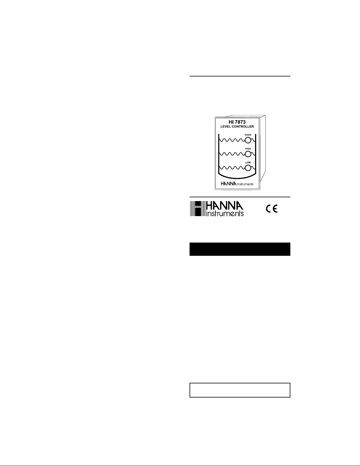
HI 7871- HI 7873
HI 7874
Level Controllers
http://www.hannainst.com
Compliance with the CE Directives
These Instruments are in
WARRANTYWARRANTY
WARRANTY
WARRANTYWARRANTY
HI 7871, HI 7873 and HI 7874 are warranted for one year
against defects in workmanship and materials when used for their intended purpose and maintained according to instructions. This warranty
is limited to repair or replacement free of charge.
Damages due to accident, misuse, tampering or lack of prescribed
maintenance are not covered.
If service is required, contact the dealer from whom you purchased the
instrument. If under warranty, report the model number, date of purchase, serial number and the nature of the failure. If the repair is not
covered by the warranty, you will be notified of the charges incurred. If
the instrument is to be returned to Hanna Instruments, first obtain a
Returned Goods Authorization Number from the Customer Service department and then send it with shipment costs prepaid. When shipping
any instrument, make sure it is properly packaged for complete protection.
To validate your warranty, fill out and return the enclosed warranty card
within 14 days from the date of purchase.
All rights are reserved. Reproduction in whole or in part is prohibited
without the written consent of the copyright owner, Hanna Instruments Inc., Woonsocket, Rhode Island, 02895 , USA.
Hanna Instruments reserves the right to modify the design, construction
and appearance of its products without advance notice.
ISTR7871R1 04/97PRINTED IN PORTUGAL
Page 2
Dear Customer,
Thank you for choosing a Hanna product. This manual will
provide you with the necessary information for the correct
operation of the instrument. Please read it carefully before
using the controller. If you need additional technical information, do not hesitate to e-mail us at tech@hannainst.com.
These instruments are in compliance with directives
EN 50081-1 and EN 50082-1.
PRELIMINARY EXAMINATIONPRELIMINARY EXAMINATION
PRELIMINARY EXAMINATION
PRELIMINARY EXAMINATIONPRELIMINARY EXAMINATION
Remove the instrument from the packing material and
examine it carefully. If any damage has occurred during
shipment, immediately notify your Dealer or the nearest
Hanna Customer Service Center.
Note: Conserve all packing material until the instrument
has been observed to function correctly. Any defective
item must be returned to the Dealer in its original
packing.
GENERAL DESCRIPTIONGENERAL DESCRIPTION
GENERAL DESCRIPTION
GENERAL DESCRIPTIONGENERAL DESCRIPTION
HI 7871 and HI 7873 are 2-wire transmitter level controllers designed especially for long distance control of liquid
levels in tanks (e.g. in biological and industrial water
treatment). A complete system should consist of:
• HI 7871 or HI 7873 level controller;
• HI 7874 transmitter and sensor holder;
• HI 7164 11-pin connector;
• 3 or 4 measuring bars.
The level transmitter is basically a molded electrode holder
with 4 sockets to screw in the level sensors. The longest bar
has to be the common electrode and connected to the COM
port. The remaining electrodes can be connected in any
sequence, after cutting them to the required lengths.
HI 7874 contains the completely resinated amplifier circuit
and the 2-wire terminal board. It also comes with a
mounting bracket for quick and easy installation.
HI 7874 uses stainless steel measuring bars and employs 9V
peak to peak A.C. to measure the liquid level. It can be
used in liquids with conductivity greater than 10 µS/cm
(µmho/cm).
HI 7871 requires only 3 electrodes, whereas HI 7873 needs 4.
HI 7871 is a basic high and low level controller. HI 7873
has an overflow alarm control as an additional feature.
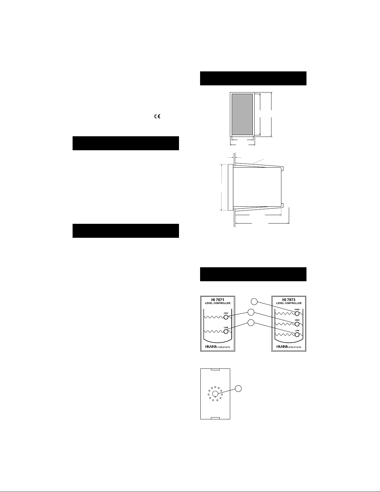
MECHANICAL DIMENSIONSMECHANICAL DIMENSIONS
MECHANICAL DIMENSIONS
MECHANICAL DIMENSIONSMECHANICAL DIMENSIONS
FRONT VIEW
73mm
79mm
2.87"
3.11"
42mm
1.65"
49mm
1.93"
SIDE VIEW
79mm
3.11"
0.25/4mm
0.01/0.160"
76mm
3"
95mm MIN
3.74"
ADJUSTABLE
LOCATION
BRACKET
Adjustable brackets (supplied) allow the controller to slide
into the cutout and hold the unit in place. 95 mm (3.74")
is the minimum space required to install the controller with
the cables connected.
FUNCTIONAL DESCRIPTIONFUNCTIONAL DESCRIPTION
FUNCTIONAL DESCRIPTION
FUNCTIONAL DESCRIPTIONFUNCTIONAL DESCRIPTION
FRONT VIEW
1
2
3
REAR VIEW
1. OVER LED (HI 7873 only)
indicates an overflow condition
2. HIGH LED indicates full tank
4
3. LOW LED indicates low liquid
level
4. 11-pin Socket
Page 3

SPECIFICATIONSSPECIFICATIONS
SPECIFICATIONS
SPECIFICATIONSSPECIFICATIONS
HI 7871 HI 7873
Level Adjustment High, Low High, Low, Over
Level Indication High, Low High, Low, Over
Transmission 300 m (990') max
Socket/Connector 11-pin connector
Sensing Bars* 34
Transmitter* HI 7874
Output Contact One, 2A/220V Two, 2A/220V
relay for up to relays for up to
1,000,000 closures 1,000,000 closures
Power Supply 110/115V or 220/240V –50/60 Hz
Environment 0 to 50°C (32 to 122°F)
Max. 85% RH non-condensing
Dimensions 79 x 49 x9 5 mm(3.1 x 1.9 x 3.7")
Weight 130 g (4.6 oz.)
* Not included with HI 7871/7873.
CONNECTIONSCONNECTIONS
CONNECTIONS
CONNECTIONSCONNECTIONS
The common terminal (#4) and #3 can also be
connected to a device to indicate a “full tank” state.
• With HI 7873, connect terminals #10 and #11 to an
alarm for monitoring Over Flow condition.
• Remove the cover of HI 7874 (bar holder) and connect
a 2-wire cable from #8 to positive (+) and #9 to
negative (–) terminals of the holder.
• Remove the 11-pin connector from the rear of the level
controller.
• Connect a 2-wire power cable to terminals #2 and #7
(no ground connection).
• Connect the output terminals #4 (common) and #5
(low) to a relay switch (max 2A/220V) to start and stop
a pump or to open and close an electrovalve. These two
contacts act only as a switch and the pump or electrovalve
have to be powered independently.
• Screw the longest bar to the hole
marked as COMM. This bar will be
used as the reference electrode. Screw
the other measuring bars into the
remaining sockets in any order. The
bars should be cut to the required
lengths for low, high and over. The
reference (COM) and the low bar
(1st) can be the same length.
• With HI 7871, connect only 3 bars
to the holder: reference, low and
high. With HI 7873, connect 4 bars
to the holder: reference, low, high
and over.
Page 4

OPERATIONAL GUIDEOPERATIONAL GUIDE
OPERATIONAL GUIDE
OPERATIONAL GUIDEOPERATIONAL GUIDE
• Turn on the power supply. After approx. 8 seconds, the
controller can activate a pump or electrovalve.
• When liquid level is below the COM (reference) or the 1
bar, LOW LED turns on and output contacts (#4 &
#5) close, activating a pump/electrovalve:
• Subsequently, when liquid level drops below the 3
rd
bar, OVER LED goes off and HIGH LED comes on. When
liquid level drops below the 2nd bar, HIGH LED goes off.
LOW LED lights up when the level drops below the 1
st
bar.
st
• HI 7873 can also detect faulty conditions, such as a
short or open circuit, in the 2-wire connection between
#8 and #9 terminals with HI 7874 bar holder.
If the 2-wire is shorted, the OVER LED
goes on and the alarm contacts close.
• When liquid level reaches the low (1st) bar, LOW LED
goes off but the contacts (#4 & #5) remain closed:
• When liquid level reaches the high (2nd) bar, HIGH LED
turns on and the output contact (#5) opens (pump/
electrovalve disactivated) while #3 & #4 close:
• With HI 7873, if after reaching HIGH level, liquid level
continues to rise and reaches the 3rd bar, the alarm
contacts close and the OVER LED comes on:
If the 2-wire is damaged and the circuit
is open, LOW LED goes on and the alarm
contacts close.
• With HI 7871, LOW LED goes on with an
open circuit. If the LOW LED remains lit
but the pump/electrovalve is not activated, it indicates an open circuit.
A short circuit will instead give a HIGH
LED indication.
Note: It takes about 8 seconds for the controller to activate
the relay from when an alarm condition occurs.
ACCESSORIESACCESSORIES
ACCESSORIES
ACCESSORIESACCESSORIES
HI 7164 11-pin connector
HI 7875/P Sensing bars, 5 pcs, 50 cm long (1.5’)
Note: The sensing bars are made in such a way that they
can be screwed into each other to provide any
required length. It is recommended to keep the bars
separate with a non-conductive material such as
plastic to ensure they do not touch each other,
specially in deep tanks.
Page 5

CE DECLARATIONCE DECLARATION
CE DECLARATION
CE DECLARATIONCE DECLARATION
OF CONFORMITYOF CONFORMITY
OF CONFORMITY
OF CONFORMITYOF CONFORMITY
Recommendations for Users
Before using these products, make sure that they are entirely suitable for the environment in which they are used.
Operation of these instruments in residential areas could cause unacceptable interferences to radio and TV equipment.
Any variation introduced by the user to the supplied equipment may degrade the
instrument's EMC performance.
For HI 7874 only:
The measuring bars at the end of the sensor are sensitive to electrostatic discharges.
Avoid touching these bars at all times.
Connection to level controller should be done with the recommended ferrite close to
level controller.
 Loading...