

Page 1
Instruction Manual
EC214
EC215 • EC215R
Multi-Range
Conductivity Meters
for Laboratories
www.hannainst.com
Page 2

PRELIMINARY EXAMINATION
Dear Customer,
Thank you for choosing a HANNA instruments® product.
Please read this instruction manual carefully before using the instru-
ment. This manual will provide you with all the necessary information
for correct operation.
If you need additional technical information, do not hesitate to e-mail
us at tech@hannainst.com.
These instruments are in compliance with the directives.
TABLE OF CONTENTS
PRELIMINARY EXAMINATION ....................................................... 3
GENERAL DESCRIPTION ............................................................... 3
FUNCTIONAL DESCRIPTION EC 214 ............................................. 4
SPECIFICATIONS EC 214 ............................................................. 5
FUNCTIONAL DESCRIPTION EC 215 ............................................. 6
SPECIFICATIONS EC 215 ............................................................. 7
OPERATIONAL GUIDE .................................................................. 8
CALIBRATION ............................................................................ 10
CONDUCTIVITY VS. TEMPERATURE CHART................................... 13
DETERMINATION OF THE TEMPERATURE
COEFFICIENT OF A SOLUTION (EC 215) ..................................... 14
PROBE MAINTENANCE ............................................................... 15
ACCESSORIES ............................................................................ 16
WARRANTY ............................................................................... 18
CE DECLARATION OF CONFORMITY............................................. 19
Remove the instrument from the packing material and examine it
carefully to make sure that no damage has occurred during shipping.
If there is any damage, notify your dealer.
Each meter is supplied complete with:
• 4-ring conductivity probe with 1 m (3.3’) cable
• HI 76300 for EC 214
• HI 76303 for EC 215 and EC 215R
• 12 Vdc adapter
• Instruction manual
Note: Save all packing material until you are sure that the instrument
functions correctly. All defective items must be returned in the
original packing with the supplied accessories.
GENERAL DESCRIPTION
EC 214 and EC 215 are bench top multi-range conductivity meters for
the laboratory.
Four measurement ranges ensure the highest resolution and precision for
your measuring requirements.
Single point calibration is performed manually simply by adjusting a
knob on the front of the meter.
Temperature compensation of the readings is automatic for the EC 215
models, thanks to the temperature sensor incorporated in probe, with
userselectable temperature coefficient.
With EC 214 the temperature compensation is manual and the temperature value can be also set with a knob.
The rugged probe with platinum 4-ring sensor responds faster than
conventional stainless steel models and can be also used for measuring
highly acidic or alkaline samples, or at high temperature.
In addition, the EC 215R model offers analog output of 0 to 5V that
represents the full conductivity scale across all 4 ranges.
2
3
Page 3
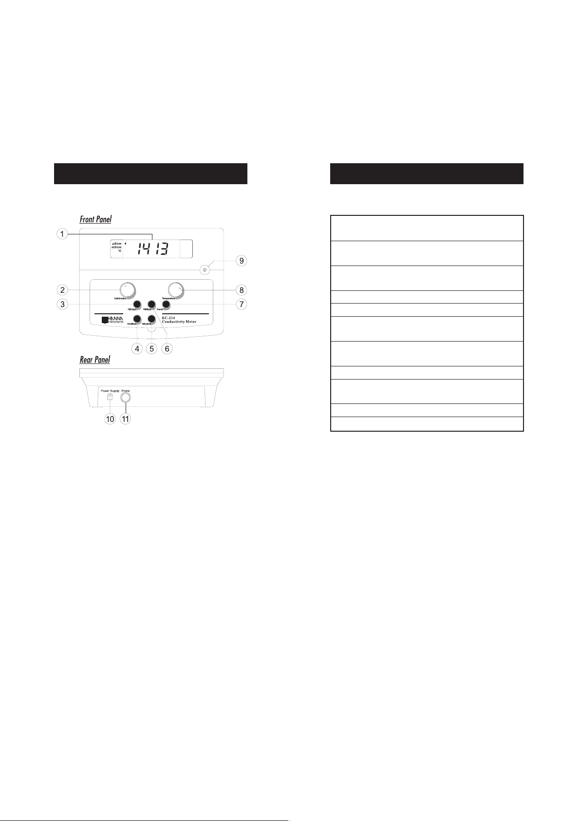
FUNCTIONAL DESCRIPTION EC 214
SPECIFICATIONS EC 214
Range 0.0 to 199.9 μS/cm / 0 to 1999 μS/cm
0.00 to 19.99 mS/cm / 0.0 to 199.9 mS/cm
Resolution 0.1 μS/cm / 1 μS/cm
0.01 mS/cm / 0.1 mS/cm
Accuracy (@20°C/68°F)
±1% FS (excluding probe error)
Typical EMC Deviation ±1% F.S.
Calibration Manual, single point, through front knob
Temperature Compensation
Manual, 0 to 50°C (32 to 122°F) with β=2%/°C
Probe HI 76300, platinum 4-ring sensor,
with 1 m (3.3') cable (included)
Power Supply 12 Vdc (power adapter included)
Environment 0 to 50°C (32 to 122°F);
RH max 95% non-condensing
Dimensions 240 x 182 x 74 mm (9.4 x 7.1 x 2.9")
Weight 1.0 kg (2.2 lb.)
1) Liquid Crystal Display (LCD)
2) Conductivity calibration knob
3) 199.9 μS key for range selection
4) 19.99 mS key for range selection
5) 199.9 mS key for range selection
6) 1999 μS key for range selection
7) COND/°C key, to select conductivity reading or temperature
setting for manual compensation
8) Temperature setting knob for manual compensation
9) ON/OFF switch
10) Power adapter socket
11) Probe connector
4
5
Page 4
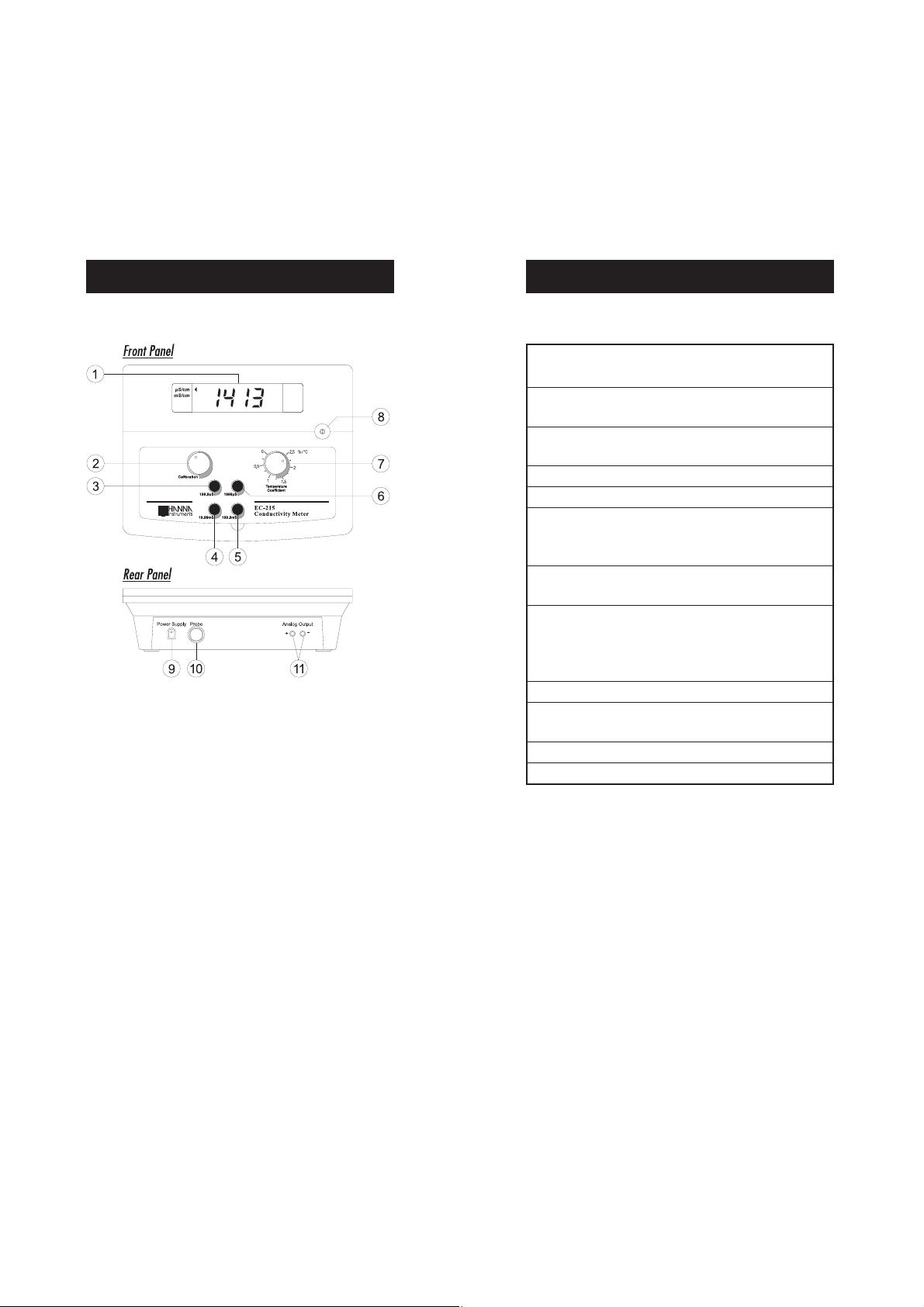
FUNCTIONAL DESCRIPTION EC 215 SPECIFICATIONS EC 215
Range 0.0 to 199.9 μS/cm / 0 to 1999 μS/cm
0.00 to 19.99 mS/cm / 0.0 to 199.9 mS/cm
Resolution 0.1 μS/cm / 1 μS/cm
0.01 mS/cm / 0.1 mS/cm
Accuracy (@20°C/68°F)
±1% F.S. (excluding probe error)
Typical EMC Deviation ±1% F.S.
Calibration Manual, single point, through front knob
Temperature Compensation
Automatic, 0 to 50°C (32 to 122°F)
with β adjustable from 0 to 2.5%/°C
Probe (included) HI 76303, platinum 4-ring sensor,
built-in temperature sensor and 1 m (3.3') cable
Analog Output (EC 215R only)
0 to 5 Vcc not isolated output;
accuracy ±0.1% of reading;
resolution ±2.5 mV
Power Supply 12 Vdc (power adapter included)
Environment 0 to 50°C (32 to 122°F);
RH max 95% non-condensing
1) Liquid Crystal Display (LCD)
2) Conductivity calibration knob
3) 199.9 μS key for range selection
4) 19.99 mS key for range selection
5) 199.9 mS key for range selection
6) 1999 μS key for range selection
7) Temperature coefficient setting knob
8) ON/OFF switch
9) Power adapter socket
10) Probe connector
11) Analog output (EC 215R only)
Dimensions 240 x 182 x 74 mm (9.4 x 7.1 x 2.9")
Weight 1.0 kg (2.2 lb.)
6
7
Page 5
OPERATIONAL GUIDE
Power connection
Plug the 12 Vdc adapter into the power supply socket.
Note: Make sure the main line is protected by a fuse.
Probe connection
Connect the conductivity probe to the proper socket on the rear panel.
Note: Make sure that the instrument has been calibrated before
taking any measurement (see “Calibration” section).
Note: If possible, use plastic beakers to minimize EMC interferences.
TAKING CONDUCTIVITY MEASUREMENTS WITH EC214
• Switch the instrument on by pressing ON/OFF.
Note: If the display shows "1", there is an over-range condition.
Select the next higher range.
• Allow a few minutes for the reading to stabilize. The LCD will
display the temperature compensated conductivity reading.
TAKING CONDUCTIVITY MEASUREMENTS WITH EC215
• Switch the instrument on by pressing ON/OFF.
• Immerse the probe in the solution while com-
pletely submerging the holes of the sleeve. Tap
the probe lightly on the bottom of the beaker to
remove any air bubbles trapped inside the
sleeve.
• Immerse the probe in the solution while completely submerging the holes of the sleeve. Tap
the probe lightly on the bottom of the beaker
to remove any air bubbles trapped inside the
sleeve. Measure the solution temperature with
a Checktemp or another accurate thermom-
eter.
• Press the “COND/°C” key to select temperature
setting.
• Adjust the “TEMPERATURE” knob to display the temperature of
the solution on the LCD.
• Press the “COND/°C” key to select conductivity
reading.
• Select the appropriate conductivity range.
• Adjust the "TEMPERATURE COEFFICIENT" knob to the temperature
coefficient value of the solution (see “Determination of the Temperature Coefficient of a Solution” section for details).
• Select the appropriate conductivity range.
Note: If the display shows "1", there is an over-range condition.
Select the next higher range.
• Allow a few minutes for the reading to stabilize. The LCD will
display the temperature compensated conductivity reading.
8
9
Page 6

CALIBRATION
The instrument should be calibrated at least once a month, or when
the probe is changed.
INITIAL PREPARATION
For better accuracy of measurements it is recommended to use the
calibration solution with a conductivity value as close as possible to
the sample to be measured. See the “Accessories” section for a
complete list of available HANNA calibration solution.
Rinse the probe thoroughly in distilled water.
If possible, use plastic beakers to minimize any EMC interferences.
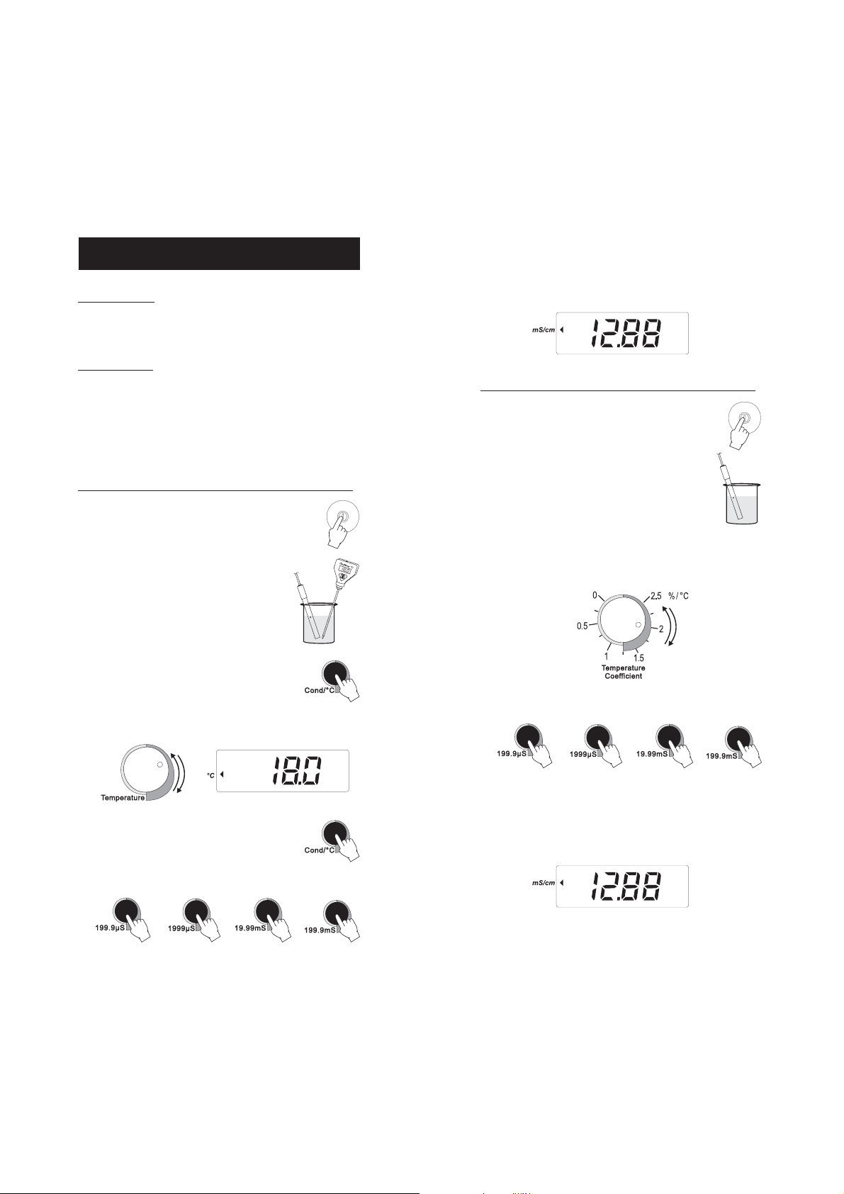
PROCEDURE FOR EC214
• Pour a small quantity of the appropriate
calibration solution, e.g. HI 7030 (12.88
mS/cm @ 25°C), into a plastic beaker.
• Immerse the probe in the solution while
completely submerging the holes of the
sleeve. Tap the probe lightly on the bottom of the beaker to remove any air
bubbles trapped inside the sleeve. Measure the solution temperature with a
Checktemp or another accurate thermometer.
• Press the “COND/°C” key to select temperature setting.
• Adjust the “TEMPERATURE” knob to display the temperature of
the solution on the LCD.
HI 7030
• Press “COND/°C” to select conductivity reading and select the appropriate range:
"199.9 μS" for HI 7033
"1999μS" for HI 7031
"19.99 mS" for HI 7030
"199.9 mS" for HI 7034
Note: If the display shows "1", there is an over-range condition.
Select the next higher range.
• Allow a few minutes for the reading to stabilize, then adjust the
“CALIBRATION” knob to read the calibration solution conductivity
value at 25°C (77°F), e.g. 12.88 mS/cm.
• All subsequent measurements will be referenced to 25°C (77°F).
• To reference the measurements to 20°C (68°F), adjust the
“CALIBRATION” knob to read the calibration solution conductivity
value at 20°C (68°F), e.g. 11.67 mS/cm. See the “Conductivity
vs. Temperature Chart” on page 13.
• Calibration is now complete and the instrument is ready for use.
PROCEDURE FOR EC215
• Pour a small quantity of the appropriate
calibration solution, e.g. HI 7030 (12.88
mS/cm @ 25°C), into a plastic beaker.
• Immerse the probe in the solution while
completely submerging the holes of the
sleeve. Tap the probe lightly on the bottom
of the beaker to remove any air bubbles
trapped inside the sleeve.
• Adjust the "TEMPERATURE COEFFICIENT" knob to 2%/°C.
HI 7030
10
11
Page 7

• Select the appropriate range:
"199.9 μS" for HI 7033
"1999μS" for HI 7031
"19.99 mS" for HI 7030
"199.9 mS" for HI 7034
Note: If the display shows "1", there is an over-range condition.
Select the next higher range.
• Allow a few minutes for the reading to stabilize, then adjust the
“CALIBRATION” knob to read the calibration solution conductivity
value at 25°C (77°F), e.g. 12.88 mS/cm.
CONDUCTIVITY VERSUS
TEMPERATURE CHART
The conductivity of an aqueous solution is the measure of its ability to
carry an electrical current by means of ionic motion.
The conductivity invariably increases with increasing temperature.
It is affected by the type and number of ions in the solution and by
the viscosity of the solution itself. Both parameters are temperature
dependent. The dependency of conductivity on temperature is expressed as a relative change per degree Celsius at a particular
temperature, commonly as %/°C.
Since a small difference in temperature causes a large change in
conductivity, the readings are usually normalized at 25°C.
• All subsequent measurements will be referenced to 25°C (77°F).
• To reference the measurements to 20°C (68°F), adjust the
“CALIBRATION” knob to read the calibration solution conductivity
value at 20°C (68°F), e.g. 11.67 mS/cm. See the “Conductivity
vs. Temperature Chart” on page 13.
• Calibration is now complete and the instrument is ready for use.
°C °F HI 7030 HI 7031 HI 7033 HI 7034 HI 7035 HI 7039
(μS/cm) (μS/cm) (μS/cm) (μS/cm) (μS/cm) (μS/cm)
0 32 7150 776 64 48300 65400 2760
5 41 8220 896 65 53500 74100 3180
10 50 9330 1020 67 59600 83200 3615
15 59 10480 1147 68 65400 92500 4063
16 60.8 10720 1173 70 67200 94400 4155
17 62.6 10950 1199 71 68500 96300 4245
18 64.4 11190 1225 73 69800 98200 4337
19 66.2 11430 1251 74 71300 100200 4429
20 68 11670 1278 76 72400 102100 4523
21 69.8 11910 1305 78 74000 104000 4617
22 71.6 12150 1332 79 75200 105900 4711
23 73.4 12390 1359 81 76500 107900 4805
24 75.2 12640 1386 82 78300 109800 4902
25 77 12880 1413 84 80000 111800 5000
26 78.8 13130 1440 86 81300 113800 5096
27 80.6 13370 1467 87 83000 115700 5190
28 82.4 13620 1494 89 84900 117700 5286
29 84.2 13870 1521 90 86300 119700 5383
30 86 14120 1548 92 88200 121800 5479
31 87.8 14370 1575 94 90000 123900 5575
EC 214 manually compensates for temperature differences with a
fixed coefficient of 2%/°C.
EC 215 automatically compensates for temperature differences, and
features an user-selectable coefficient that can be manually adjusted
through a front knob, from 0 (no compensation) to 2.5%/°C.
12
13
Page 8

DETERMINATION OF THE TEMPERATURE
COEFFICIENT OF A SOLUTION (EC 215)
PROBE MAINTENANCE
• Immerse the probe into a solution sample and adjust the
“TEMPERATURE COEFFICIENT” knob to 0% (no compensation).
• Condition sample and probe at 25°C, and note the conductivity
reading C25.
• Condition sample and probe to a temperature t°C (approximately
5°C to 10°C different from 25°C), and note the conductivity
reading Ct.
• The temperature coefficient (β)of the solution is then calculated
using the following formula:
β = 100 x (Ct - C25) / [(t - 25) x C25]
The above procedure is suitable for determining the temperature
coefficient in the laboratory where the temperature of the solution can
be determined and controlled.
If this is not possible, e.g. during on-site measurements, the following
procedure should be used:
• Immerse the probe into the test solution and turn the “TEMPERATURE COEFFICIENT” knob to 0% (no compensation).
• Allow the conductivity reading to stabilize (the reading should not
change by more than ±0.2 mS within 1 minute) and record the
value, C.
• Repeat the procedure with a different solution temperature,
changed by more than 10°C. Wait for the reading to stabilize.
• Adjust the “TEMPERATURE COEFFICIENT” knob until the display
reads the previously recorded “C” value.
• The value indicated by the knob is the temperature coefficient of
the solution.
After every series of measurements,
rinse the probe with tap water.
If a more thorough cleaning is required, remove the sleeve and clean
the probe with a cloth or a nonabrasive detergent.
After cleaning the probe, always
re-calibrate the instrument.
The 4-ring platinum probe body is
made of glass. For this reason great
care while handling the probe must
be taken.
14
15
Page 9

ACCESSORIES
CONDUCTIVITY PROBES
HI 76300 Platinum 4-ring conductivity probe with 1 m
(3.3') cable (for EC214)
HI 76303 Platinum 4-ring conductivity probe with built-
in temperature sensor and 1 m (3.3') cable
(for EC215)
CONDUCTIVITY CALIBRATION SOLUTIONS
HI 7030M 12880 μS/cm, 230 mL bottle
HI 7030L 12880 μS/cm, 500 mL bottle
HI 8030L 12880 μS/cm, 500 mL FDA bottle
HI 7031M 1413 μS/cm, 230 mL bottle
HI 7031L 1413 μS/cm, 500 mL bottle
HI 8031L 1413 μS/cm, 500 mL FDA bottle
HI 7033M 84 μS/cm, 230 mL bottle
HI 7033L 84 μS/cm, 500 mL bottle
HI 8033L 84 μS/cm, 500 mL FDA bottle
HI 7034M 80000 μS/cm, 230 mL bottle
HI 7034L 80000 μS/cm, 500 mL bottle
HI 8034L 80000 μS/cm, 500 mL FDA bottle
HI 7035M 111800 μS/cm, 230 mL bottle
HI 7035L 111800 μS/cm, 500 mL bottle
HI 8035L 111800 μS/cm, 500 mL FDA bottle
HI 7039M 5000 μS/cm, 230 mL bottle
HI 7039L 5000 μS/cm, 500 mL bottle
HI 8039L 5000 μS/cm, 500 mL FDA bottle
OTHER ACCESSORIES
HI 98501 ChecktempC electronic thermometer (range -
50.0 to 150.0°C)
HI 710005 115 Vac / 12 Vdc voltage adapter, US plug
HI 710006 230 Vac / 12 Vdc voltage adapter, European
plug
HI 740036 100 mL plastic beaker (6 pcs)
HI 740034 Cap for 100 mL beakers (6 pcs)
HI 76404 Probe holder
PROBE MAINTENANCE SOLUTIONS
HI 7061M General cleaning solution, 230 mL bottle
HI 8061M General cleaning solution, 230 mL FDA bottle
HI 7061L General cleaning solution, 500 mL bottle
HI 8061L General cleaning solution, 500 mL FDA bottle
16
17
Page 10

WARRANTY
All Hanna Instruments meters are guaranteed for two years
against defects in workmanship and materials when used for their
intended purpose and maintained according to instructions.
Electrodes and the probes are guaranteed for six months.
This warranty is limited to repair or replacement free of charge.
Damages due to accident, misuse, tampering or lack of prescribed
maintenance are not covered.
If service is required, contact the dealer from whom you purchased the
instrument.
If under warranty, report the model number, date of purchase, serial
number and the nature of the failure.
If the repair is not covered by the warranty, you will be notified of the
charges incurred.
If the instrument is to be returned to Hanna Instruments, first obtain
a Returned Goods Authorization number from the Customer Service
department and then send it with shipping costs prepaid.
When shipping any instrument, make sure it is properly packaged for
complete protection.
CE DECLARATION OF CONFORMITY
All rights are reserved. Reproduction in whole or in part is
prohibited without the written consent of the copyright owner.
Hanna Instruments reserves the right to modify the design,
construction and appearance of its products without advance notice.
18
Recommendations for Users
Before using these products, make sure that they are entirely suitable for the environment in which they are used.
Operation of these instruments in residential area could cause unacceptable interferences to radio and TV
equipments, requiring the operator to take all necessary steps to correct interferences.
The metal band at the end of the sensor is sensitive to electrostatic discharges. Avoid touching this metal
band at all times. During calibration of instruments, ESD wrist straps should be worn to avoid possible
damage to the sensor by electrostatic discharge. Use plastic beakers to minimize any EMC interferences.
Any variation introduced by the user to the supplied equipment may degrade the instruments' EMC
performance.
To avoid electrical shock, do not use these instruments when voltages at the measurement surface exceed 24
Vac or 60 Vdc.
To avoid damages or burns, do not perform any measurement in microwave ovens.
19
Page 11

SALES AND TECHNICAL SERVICE CONTACTS
Australia:
Tel. (03) 9769.0666 • Fax (03) 9769.0699
China:
Tel. (10) 88570068 • Fax (10) 88570060
Egypt:
Tel. & Fax (02) 2758.683
Germany:
Tel. (07851) 9129-0 • Fax (07851) 9129-99
Greece:
Tel. (210) 823.5192 • Fax (210) 884.0210
Indonesia:
Tel. (21) 4584.2941 • Fax (21) 4584.2942
Japan:
Tel. (03) 3258.9565 • Fax (03) 3258.9567
Korea:
Tel. (02) 2278.5147 • Fax (02) 2264.1729
Malaysia:
Tel. (603) 5638.9940 • Fax (603) 5638.9829
Singapore:
Tel. 6296.7118 • Fax 6291.6906
MANEC215R3 10/05
South Africa:
Tel. (011) 615.6076 • Fax (011) 615.8582
Taiwan:
Tel. 886.2.2739.3014 • Fax 886.2.2739.2983
Thailand:
Tel. 66.2619.0708 • Fax 66.2619.0061
United Kingdom:
Tel. (01525) 850.855 • Fax (01525) 853.668
USA:
Tel. (401) 765.7500 • Fax (401) 765.7575
For e-mail contacts and complete list of Sales and
Technical offices, please see www.hannainst.com
 Loading...