

Page 1
Instruction Manual
C 114
Multiparameter
Turbidity &
Free and Total Chlorine
This Instrument is in Compliance with the CE Directives
www.hannainst.com
Page 2

Dear Customer,
Thank you for choosing a Hanna Product.
Please read this instruction manual carefully
before using the instrument.
This manual will provide you with the necessary
information for the correct use of the instrument,
as well as a precise idea of its versatility. If you
need more technical information, do not hesitate to e-mail us at tech@hannainst.com.
This instrument is in compliance with directives EN 50081-1 and EN 50082-1.
TABLE OF CONTENTS
Preliminary Examination ............................. 3
General Description.................................... 4
Principle of Operation ................................. 6
Functional Description ................................ 9
Specifications ........................................... 12
Operational Guide ..................................... 13
Calibration ................................................ 19
PRELIMINARY EXAMINATION
Remove the instrument from the packing material and examine it to make sure that no
damage has occurred during shipping. If there
is any damage, notify your Dealer.
C114 is supplied complete with:
• 1.5V AA Size Batteries (4 ea.)
• Glass Cuvet
• Cap
In addition to the above items, an optional
starter kit HI 731327 is available, supplied
with:
• Measurement cuvets (2 pcs)
• Primary calibration standards:
HI 93102-0 AMCO-AEPA-1 0 NTU* cali-
bration solution, 30 mL
HI 93102-20 AMCO-AEPA-1 20 NTU* cali-
bration solution, 30 mL
• HI 93703-50 Cleaning solution, 230 mL
• HI 731318 Tissue for wiping the cuvets
(4 pcs)
• HI 710031 Rugged carrying case
Diagnostic mode ....................................... 27
Logging with C 1 14 ................................... 28
User-selectable Shutdown......................... 30
Battery Replacement................................. 31
Diagnostic Codes ..................................... 32
Accessories.............................................. 33
Warranty................................................... 34
CE Declaration of Conformity ................... 3 5
ISO 9000 Certified
Company since 1992
2
Note: Save all packing material until you are
sure that the instrument functions correctly. Any defective item must be returned in its original packaging with
the supplied accessories.
* 1 NTU (Nephelometric Turbidity Unit) = 1 FTU
(Formazine Turbidity Unit)
3
Page 3

GENERAL DESCRIPTION
The Hanna C114 is a portable microprocessor driven, multiparameter instrument. The
meter measures Free & Total Chlorine and
Turbidity.
In the colorimetric mode, the user can select
either factory preprogrammed calibration settings or calibrate the meter using customized
calibration values based on the concentration
or relative absorbance of the sample. Calibration data is also stored in a non-volatile
EEPROM.
In the turbidity mode, periodic recalibration of
the meter with primary standards according
to regulatory requirements or personal experience is suggested. Turbidity ranges are 0.00-
9.99 NTU and 10.0-50.0 NTU.
C114 complies with G.L.P. Standards (Good
Laboratory Practice), that is:
• When switched on, the LCD displays all
segments (display check).
• Battery status is monitored during every
measurement cycle warning the user if the
batteries become weak. In addition, C102
will turn itself off before low voltage causes
erroneous readings.
• It utilizes a real time clock and recalls
calibration data such as date, time and
calibration values.
digits and can display the measured parameter in hundredths. The lower level has three
characters and indicates current mode (e.g.
F CL for free chlorine or TR for turbidity).
Different LCD segments indicate low battery,
logging mode, date, time, etc.
A pure Green LED has been utilized as a
light source for both turbidimetric and colorimetric measurements. A silicon photocell is
used to receive transmitted light from colorimetric channel while another photocell receives scattered light from the turbidimetric
(nephelometric) channel.
In order to measure chlorine parameters, all
the operator has to do is zero the blank
sample and then add 1 packet of reagent.
After placing the cuvet back in the meter and
pressing READ, the measurements are shown
directly on the LCD.
The instrument operates with four AA batteries and may be operator-programmed to turn
itself off automatically after 10, 20, 30, 40, 50
or 60 minutes of inactivity.
C114 and all accessories such as sample
vials, reagent pillows, primary standards, can
be easily stored in the optional carrying case
(HI 710031).
To facilitate field tests, the meter provides a
logging mode. In this mode, the user can
store up to twenty five time-tagged measurements in RAM and scroll the memory at any
time.
There are eight keys for the different operational modes. The large Liquid Crystal Display is dual-level: the upper level has four
4
5
Page 4
PRINCIPLE OF OPERATION
Turbidity Mode
C 114 has been designed to perform mea-
surements according to the USEPA’s 180.1
method and the Standard Method 2130B.
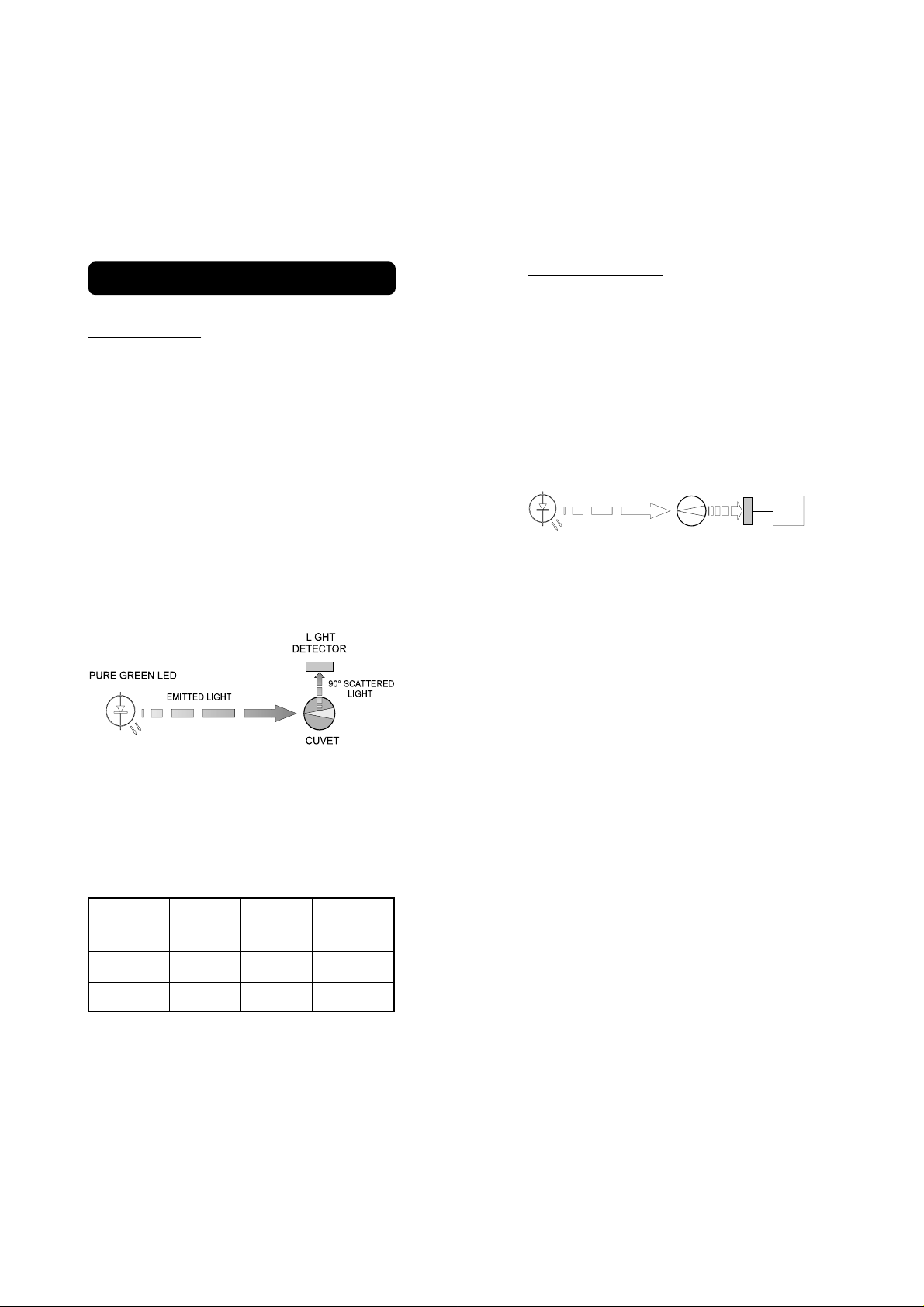
The instrument functions by passing a beam
of light through a vial containing the sample
being measured.
The light source is a Pure Green LED to
ensure that any interference caused by a
colored samples is minimized.
A sensor, positioned at 90° with respect to
the direction of light, detects the amount of
light scattered by the undissolved particles
present in the sample. The microprocessor
converts such readings into NTU* values.
Colorimetric Mode
The color of every object we see is determined by a process of absorption and emission of the electromagnetic radiation (light) of
its molecules.
Colorimetric analysis is based on the principle
that specific compounds react with others to
form a color, the intensity of which is
proportional to the concentration of the
substance being measured.
LED
EMITTED LIGHT
CUVET MICROPROCESSOR
Block diagram of an ion specific measurement
LIGHT
DETECTOR
When a substance is exposed to a beam of
light intensity Io, a portion of the radiation is
absorbed by the substance's molecules and
a radiation of intensity I, lower than Io, is
emitted.
The quantity of radiation absorbed is given by
the Lambert-Beer Law:
log Io/I = ελ c d
NTU units are equal to FTU units. However,
there are other known measurement units for
turbidity, namely the Jackson Turbidity Unit
(JTU) based on the old method of Jackson's
candle, and Silica Unit (mg / L of SiO2). The
conversion table between these measurement
units is shown below:
JTU NTU/FTU SiO2 (mg/L)
JTU 1 19 2.5
NTU/FTU 0.053 1 0.13
SiO2 (mg/L) 0.4 7.5 1
6
* 1 NTU = 1 FTU
Where log Io/I = Absorbance (A)
ελ= molar extinction coefficient of the
substance at wavelength λ
c = molar concentration of the
substance
d = optical distance light travels
through the sample
Since other factors are known, the concentration "c" can be calculated from the color
intensity of the substance determined by the
emitted radiation I.
An LED (Light Emitting Diode) emits radiation
at a relatively narrow spectrum, supplying the
system with the intensity Io.
7
Page 5
A substance absorbs a color complimentary
to the color it emits. For example, a
substance appears yellow because it absorbs
blue light. As a result, the Hanna meters use
LED’s with specific wavelengths to measure
samples.
The optical distance (d) is measured by the
internal diameter of the cuvet containing the
sample.
The photoelectric cell collects the radiation I
that is not absorbed by the sample and
converts it into an electric current.
The microprocessor converts the value into
the desired measuring unit and displays it on
the LCD.
The measurement process is done in two
phases: setting the meter to zero and actual
measurement.
The cuvet is an optical element and hence
has an important role in the measurement
process. Both the measurement and the
calibration cuvets must be optically identical
to provide the same measurement conditions.
It is also important that the surface of the
cuvet is clean and free from scratches or
dents, in order to avoid measurement
interference due to unwanted reflection and
absorption of light.
It is recommended that wherever possible the
cuvet walls are not touched by the operator.
Furthermore, in order to maintain the same
conditions during the zeroing and the
measuring phases, it is necessary to close
the cuvets to prevent any contamination.
8
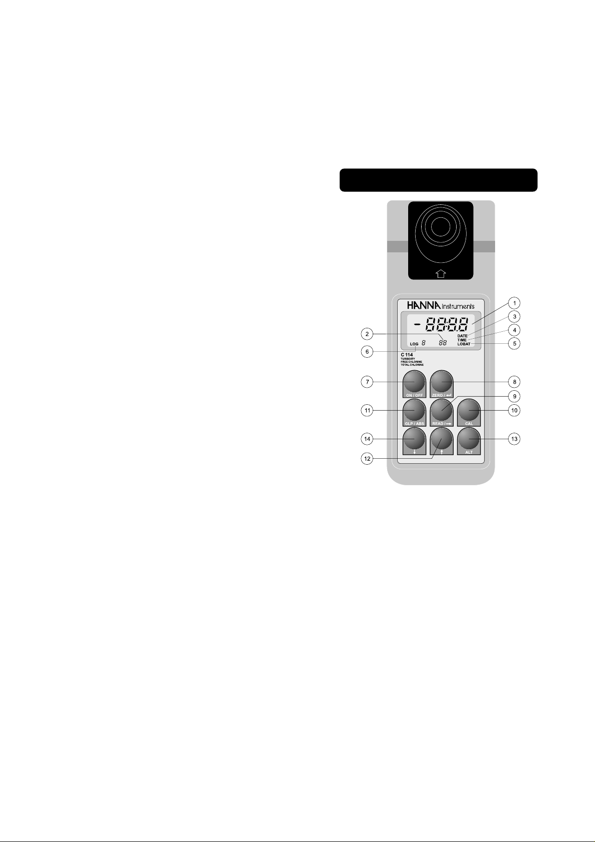
FUNCTIONAL DESCRIPTION
1) Primary
LCD: The four-digit LCD shows all
segments for several seconds
when the meter is switched
on. It then displays four
dashes to indicate “ready to
measure”. It is also the area
where the date, time and value
of last calibration are shown.
In “Read” and “Zero” mode,
“SIP” is shown to indicate
“Sample In Progress”. The
upper level also indicates the
concentration or turbidity of
the sample, as well as differ-
9
Page 6

ent diagnostic modes, such
as “-BA-” for low battery.
2) Secondary
LCD: The three-digit LCD shows the
current mode of measurement
that is “F CL”, “tCL”, “tr”,
and diagnostic or calibration
modes, such as “d11”,
“2 Fn”, “5c1”.
3) DATE: Indicates that the upper level
of LCD is showing the current date, the date of last calibration or the date of logged
measurement in memory.
4) TIME: Indicates that the upper level
of LCD is showing the current time, the time of last calibration or the time of logged
measurement in memory.
5) LOBAT: Blinking segment warns user
of low battery voltage.
6) LOG: If intermittent, it indicates that
the user is in the scroll mode
viewing the logged measurements. If fixed, it indicates
that the meter is in the log
mode and every reading
taken will be stored in
memory.
7) ON/OFF key:Turns the meter on and off.
8) ZERO/ key: In ion specific (colorimet-
ric) mode, it zeros the
sample. In calibration and diagnostic modes, it functions
as ENTER (not used in turbidity mode).
9) READ/ key: Takes the measurement of
concentration/turbidity of the
sample which is shown on
the LCD. In diagnostic or calibration mode, shifts the flashing digit to the right.
10) CAL key: If pressed during calibration,
the calibration procedure will
be aborted and the last calibration data will be reinstated.
If pressed together with the
ALT key for less then 3 seconds, the diagnostic mode will
be entered. If pressed together with the ALT key again,
the meter will quit diagnostic
mode. If pressed for more
then 3 seconds, an intermittent “CAL” prompt will appear on the upper LCD level
and the calibration procedure
is entered.
11) GLP/Abs key: In ion specific mode, it
will toggle concentration/absorbance readings on the upper LCD. In turbidity mode,
date, time and the two calibration values of the current
mode will be shown. If pressed
in time/date setup mode, the
meter will quit current mode
without making any changes
to current time/date.
12) key Scrolls upwards through the
parameters to be measured.
In calibration/diagnostic
mode, increments the blinking digit by one. If pressed
together with ALT while the
meter is in logging mode, the
upper LCD will show the data
(date/time/value) in the
10
11
Page 7

memory.
13) ALT key: Alternative functions.
OPERATIONAL GUIDE
14) key: Scrolls downwards through
the parameters to be measured. In calibration/diagnostic mode, decreases the blinking digit by one. If pressed
together with ALT while the
meter is in logging mode, the
upper LCD will show the current lot number.
SPECIFICATIONS
C 114
Range Turbidity 0.00 to 50.0 NTU*
Free Cl 0.00 to 2.50 mg/L
Total Cl 0.00 to 3.50 mg/L
Resolution
Turbidity 0.01 and 0.1 NTU*
Free Cl 0.01 mg/L
Total Cl 0.01 mg/L
Accuracy
Turbidity ±0.5 NTU* or ±5% (whichever greater)
Free Cl ±0.03 mg/L; ±3%
Total Cl ±0.03 mg/L; ±3%
Light Source Pure Green LED
Light Source Life Life of the instrument
Light Detector Two Silicon Photocells
Power Source 4 x 1.5V AA alkaline batteries
Battery Life 60 hours or 1000 measurements
Automatic Selectable
Shutdown 10, 20, 30, 40, 50 or 60 min.
Operating 0 to 50°C (32 to 122°F)
Conditions 95% RH max (non-condensing)
Dimensions 220 x 82 x 66 mm
(8.7 x 3.2 x 2.6")
Weight 510 g (18 oz.)
* 1 NTU = 1 FTU
12
SET CURRENT TIME/DATE
To set or change the current time, turn on the
meter. After initialization routine, the LCD will
show:
Press and hold the ALT and GLP keys together. Display will show the current date in
MM.DD format (e.g. August 28 is shown as
08.28).
+
Release the keys. The month digits will blink.
Make the necessary adjustments with the
and keys. To skip to the day digits, press
the key.
After the adjustments, press the key. The
unit will store the newly set month-day data
in its EEPROM and will show the current
time by a 24 hour clock HH.MM format, e.g.
2:28 pm is:
Similarly, make the necessary adjustments
as described above and press . The newly
set up “month - day - hour - minute” data will
be stored in memory.
13
Page 8
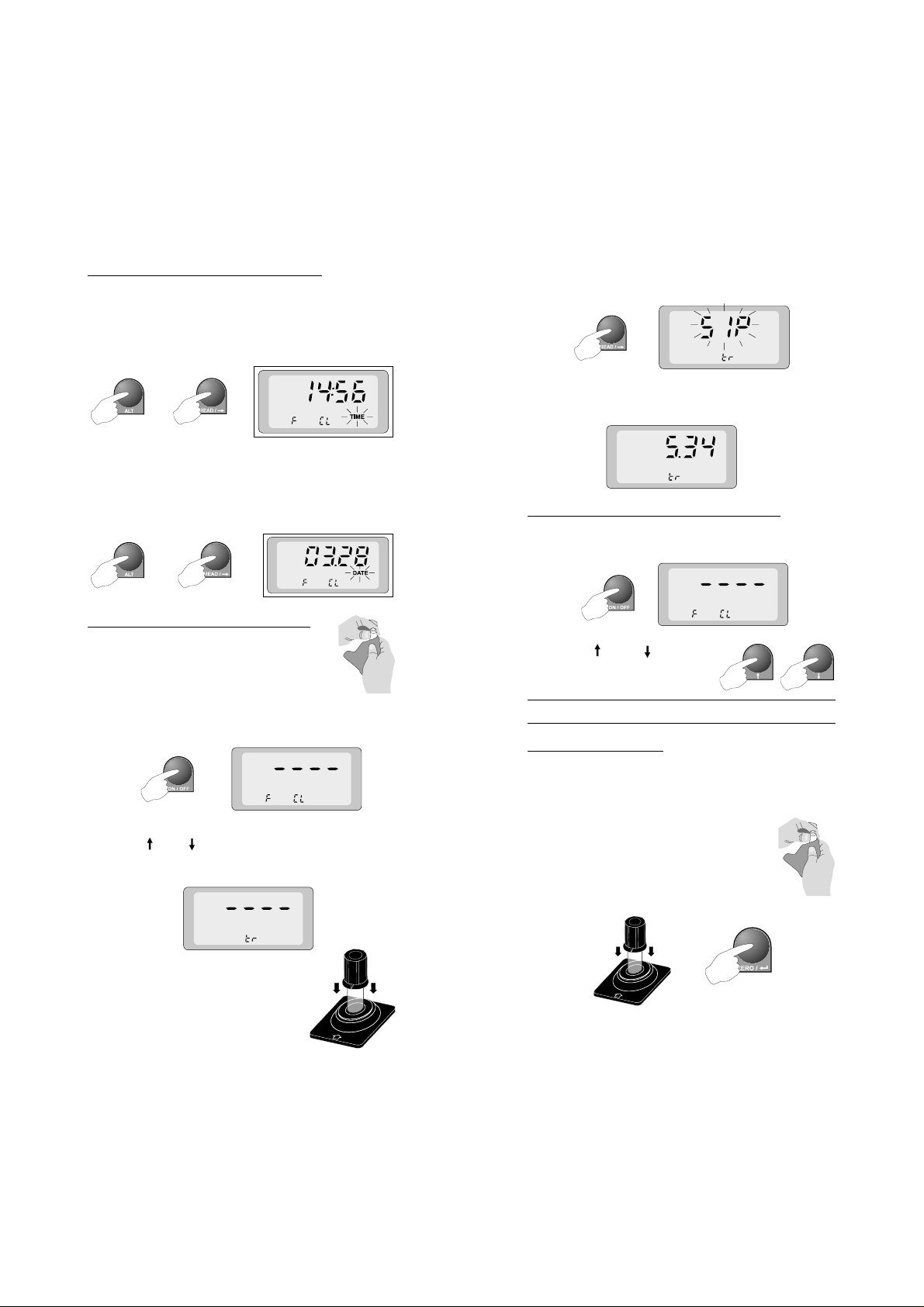
CURRENT TIME/DATE RECALL
To recall current TIME/DATE press and hold
the ALT and READ keys together. The current time and an intermittent “TIME” will be
displayed.
+
Release the keys.
Press and hold the ALT and READ keys
again and the meter will show the current
date together with an intermittent “DATE”.
+
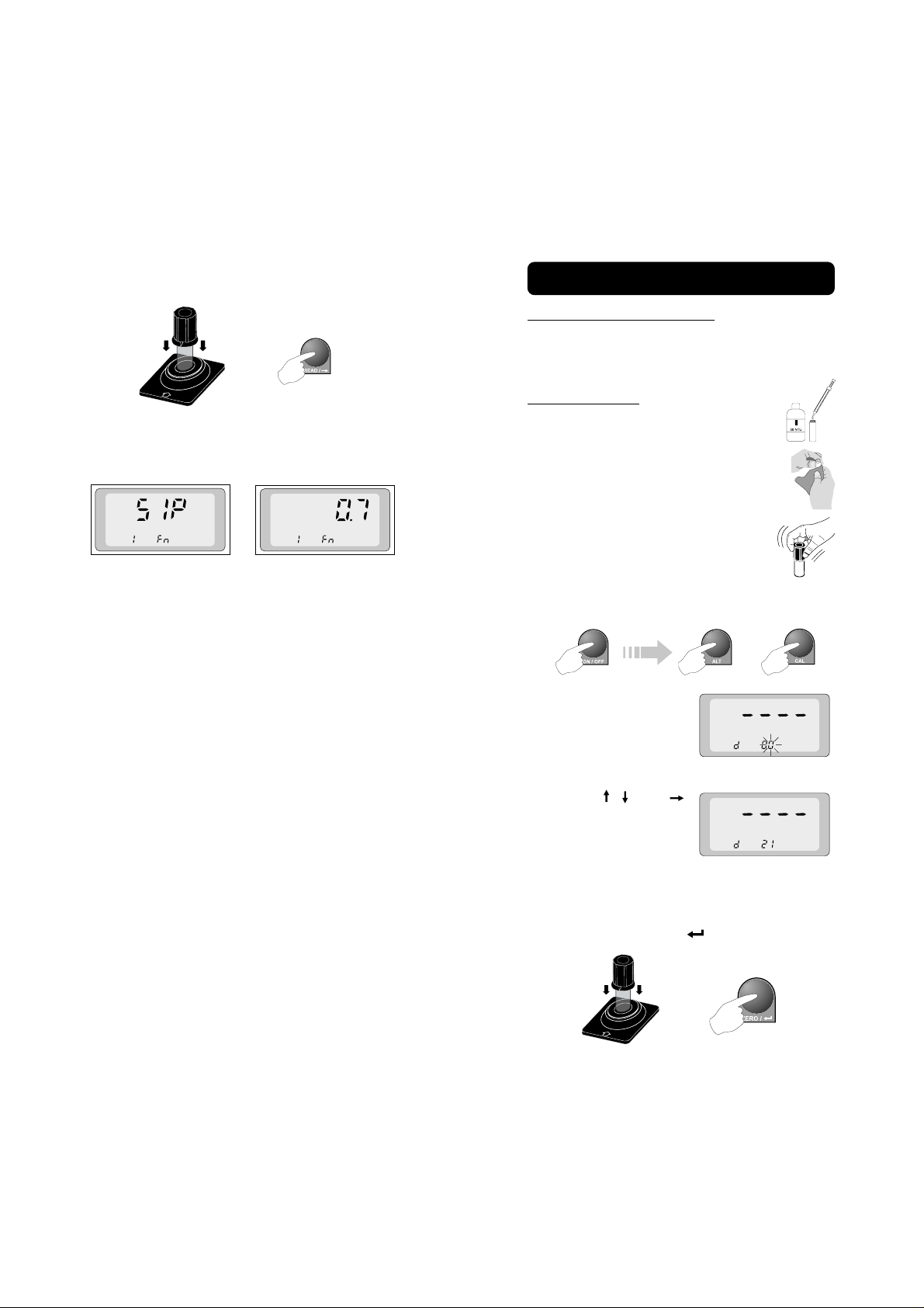
TURBIDITY MEASUREMENTS
Press READ. The meter will intermittently display “SIP” on the upper level of the LCD.
After a few seconds the display will show the
turbidity value, e.g. 5.34 NTU:
COLORIMETRIC MEASUREMENTS
Turn the meter on. After the initialization routine, the LCD will display:
Fill the vial with the sample. The
surface of the vial should be clean
and scratch free.
Turn the meter on. After the initialization routine, the LCD will show:
Use the and keys to set the lower level of
the LCD to turbidity (tr).
Insert the sample into the cuvet
holder and ensure that the
notch on the cap is positioned
securely into the groove.
14
Use the and keys to
choose the desired parameter:
F CL Free Chlorine t CL Total Chlorine
Measuring Chlorine
Fill the vial with the sample (blank). The surface of the vial should be clean and scratch
free.
Insert the blank sample into the cuvet holder and ensure that the notch
on the cap is positioned securely
into the groove. Press ZERO.
15
Page 9

The meter will show “SIP” for a few seconds
and then a zero indication:
For the Free or Total Chlorine add the content of its respective packet:
1 x1 x
1 x
1 x1 x
Replace the cap and shake the cuvet. For
best results wait 2½ mins. for Total Chlorine.
Insert the reacted sample into the cuvet holder
and ensure that the notch on the cap is positioned securely into the groove. Press READ.
The meter will show “SIP” for a few seconds
and then the concentration:
The LCD will show four
dashes on the upper
and “d 00” on the lower
part of the LCD with the
second “0” flashing:
Using the , and
keys change the lower
row of the display to
show “d 11”:
Press the key. This key is also used as a
toggle between
(FCT) programmed functions. Select the
USER mode (if necessary by pressing the
key more than once):
Press ALT and CAL until four dashes are
displayed on the upper display and “# fn” are
shown in the lower part of the LCD.
USER
(USR) and
FACTORY
Measurements in user-customized mode
Note: The meter must be calibrated for this
purpose. Follow the two-point customized calibration on page 26 before
proceeding.
Turn the meter on and by momentarily pressing both ALT and CAL.
+
16
Using the and keys select the number
from 0 to 1 where the appropriate calibration
data have been stored.
Add the appropriate reagent into the blank
sample cuvet. Shake and allow a few seconds for color to develop.
Insert the reacted sample into the cuvet holder
and make sure that the notch on the cap is
17
Page 10
positioned securely into the groove. Press
READ.
The meter will first show “SIP” for a few
seconds and afterwards the sample concentration:
CALIBRATION
TURBIDITY CALIBRATION
The meter should be properly calibrated with
a standard prepared as described in USEPA
method 180.1.
Span calibration
To calibrate the span of the meter,
fill the cuvet with the primary turbidity formazine standard of 50NTU.
Inspect and clean thoroughly the surface of the vial.
Shake the standard vigorously for a
few seconds and wait a few minutes
for the bubbles to disappear.
Turn the meter on and press both ALT and
CAL momentarily.
+
The LCD will show four
dashes on the upper
and “d 00” on the lower
part of the LCD with
the second “0” blinking.
18
Using the , and
keys change the lower
row of the display to
show “d 21”.
Insert the previously prepared 50 NTU standard into the cuvet holder and make sure that
the notch on the cap is positioned securely
into the groove. Press .
19
Page 11

The display will blink
“-Lt-” for several seconds, indicating that the
LED is being adjusted
for the turbidimetric channel.
Afterwards, a sequence of numbers between
-511 to 512 will appear on the upper part of
the LCD indicating different levels of LED light
intensity.
In approximately one minute, the adjustment
will be made and the calibration data stored
in the non-volatile memory.
The display will show four
dashes again indicating
the end of the span calibration procedure.
Press the ALT and CAL
keys together again to
leave the diagnostic mode.
Two-point customized calibration
To enter the turbidity calibration mode, the
meter should be in “turbidity” mode.
+
If the CAL key is not
pressed, the upper display will show “----”, indicating that calibration
mode was not entered. In which case, hold
down the ALT and CAL keys together for 3
seconds to restart the procedure.
After entering the calibration mode, the display will show the first
point of the previous
calibration. The most
significant digit will also be blinking.
Using the , , keys, set the turbidity of
first calibration standard (from 0.00 to 50.0 NTU).
Insert the standard vial into the cuvet holder
and ensure that the notch is positioned securely into the groove. Press the key. The
display will indicate Sample In Progress (SIP).
Use the and keys
to set the lower level of
the LCD to “tr”.
To enter the calibration mode, press and hold
the ALT and CAL keys together for at least
three seconds. The upper display will start
flashing “CAL” for approximately three seconds.
+
To confirm entry into the calibration
mode, press the CAL key again
while “CAL” is blinking.
20
After the first calibration point is memorized, the LCD will indicate the second point
of the previous calibration with the most significant digit blinking.
Using the , , keys, set the turbidity of the
second calibration standard (from 0.00 to 50.0
NTU). Insert the standard into the cuvet holder
and make sure that the notch is positioned
securely into the groove. Press the key.
The display will indicate “SIP” again.
21
Page 12
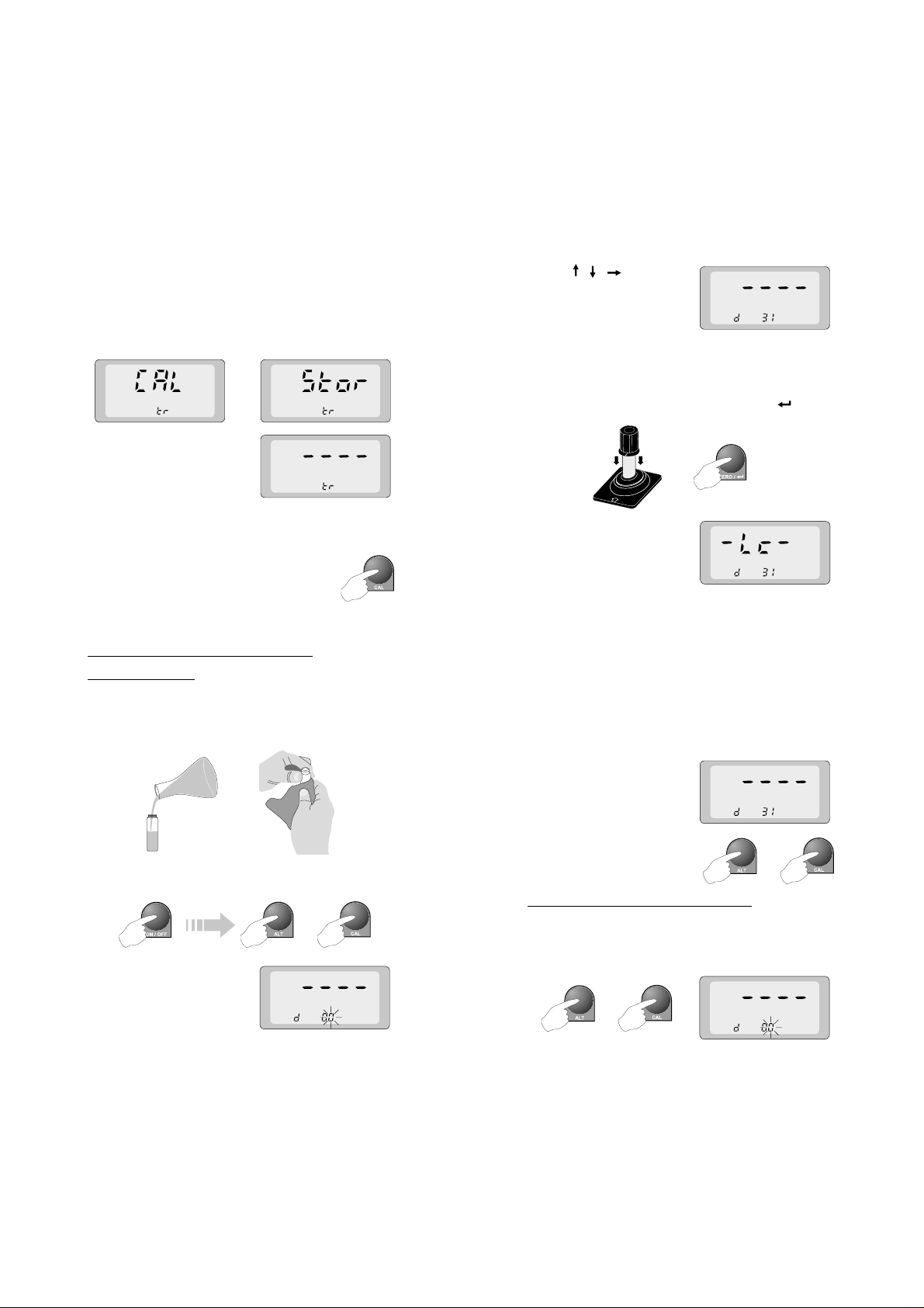
After the second calibration point is memorized, the unit will store the calibration data
together with time and date in the EEPROM
while intermittently indicating “CAL” and “Stor”
for several seconds.
Subsequently, the upper display will show
“----”, indicating that the
meter is calibrated and
ready to measure turbidity of an unknown
sample.
By pressing CAL during calibration,
user can quit the calibration mode
at any time without changing the
previously stored calibration data.
COLORIMETRIC CALIBRATION
Zero calibration
To calibrate the span of the meter, fill the
cuvet with a clean deionized water sample.
Inspect and thoroughly clean the surface of
the vial.
Turn the meter on and press both ALT and
CAL momentarily.
+
The display will show
four dashes and “d 00”.
The second “0” will blink
to allow the user to
make a selection.
22
Using , , keys set
the lower part to “d 31”.
Insert the previously prepared deionized water standard into the cuvet holder and make
sure that the notch on the cap is positioned
securely into the groove. Press the key.
The display will blink
“-Lc-” for several seconds, indicating that
adjustment of the LED
for the colorimetric measurements is in
progress.
After this, a sequence of numbers between
-511 to 512 will appear on the upper LCD
indicating the different levels of LED light
intensity. In approximately one minute, the
adjustment will be made and the calibration
data will be stored in the non-volatile memory.
Display will show four
dashes again indicating
the end of the zero calibration procedure.
Press the ALT and CAL
keys again to leave the
diagnostic mode.
Two-point customized calibration
To enter the colorimetric calibration mode, press
momentarily both the ALT and CAL keys. The
LCD will show four dashes and “d00”.
+
+
23
Page 13
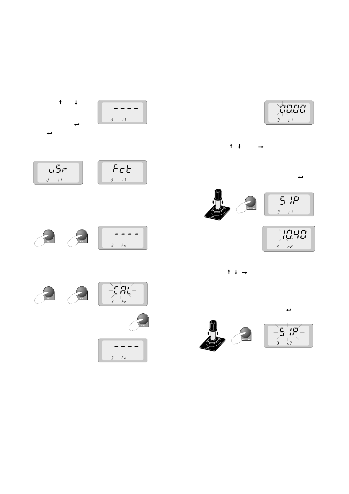
Using the and keys,
set the lower part of
the LCD to “d 11” and
then press the key.
The key is used as a toggle function in
this mode and allows the user to select between
USER
(USR) or
grammed functions.
Select the USER mode and press ALT and
CAL keys together to leave the diagnostic
mode. The display of the meter will indicate
four dashes together with a number 0 or 1 on
the lower part of the LCD.
FACTORY
(FCT) pro-
+
Press and hold the ALT and CAL keys together for at least three seconds. The upper
display will start flashing “CAL” for approximately three seconds.
+
To confirm entry into the calibration mode, press the CAL key again
while “CAL” is still blinking.
If the CAL key is not
pressed, the upper row
of the display will show
“----”, indicating that the
calibration mode was
not entered. In which case, hold down the
ALT and CAL keys together for 3 seconds to
restart the procedure.
After entering the calibration mode, the display will show the first
point of the previous
calibration with the most
significant digit blinking.
Using the , and keys, choose the
concentration of the first calibration standard.
Insert the known standard into t he c uvet holder
and make sure that the notch is positioned
securely into the groove. Press the key.
The display will indicate sample in progress.
After the first calibration point is memorized, the LCD will indicate the second point
of the previous calibration with the most significant digit blinking.
Using the , , keys, choose the known
concentration of the second calibration standard.
Insert the standard into the cuvet holder and
make sure that the notch is positioned securely into the groove. Press the key. The
display will blink “SIP” again.
After the second calibration point is memorized, the unit will store the calibration data,
time and date in the EEPROM while intermittently indicating “CAL” and “Stor” for several
seconds.
24
25
Page 14

Subsequently, the upper display will show
“----”, indicating that the
meter is calibrated and
ready to measure the
concentration of an unknown sample.
By pressing the CAL key during
calibration, user can leave the calibration mode at any time without
changing the previously stored calibration data.
DIAGNOSTIC MODE
C 114 facilitates operations by providing a
diagnostic mode. In this mode, user can set
or verify different parameters necessary to
ensure optimum performance of the meter.
To enter the diagnostic mode, turn the meter
on and momentarily press ALT and CAL together. The display will show four dashes together with “d 00”:
+
Using the , and keys, select the required diagnostic mode and press the key.
The meter will execute one of the following
user-diagnostic functions:
10 Customizes automatic shutdown
11 Selects User or Factory functions
12 Turns logging mode on or off
21 Calibrates span in turbidimetric mode
31 Calibrates span in colorimetric mode
40 Clears the logged memory
26
The following diagnostic modes are reserved
for authorized service technicians:
00 Shows the
01 Shows the
02 Shows the
05 Shows the
06 Shows 5V on-board level
07 Shows battery voltage level
08 Shows 1.23V reference voltage level
09 Shows -5V on-board level
99 Shows software version number
Blank
level in colorimetric mode
Sample
level in colorimetric mode
Dark
level in colorimetric mode
Ground
voltage
27
Page 15

To quit diagnostic mode,
press the ALT and CAL
keys together again.
LOGGING WITH C 114
C 114 allows user to log 25 time/day-tagged
measurements. User can easily turn the logging mode on and off, review the logged
memory, review the current lot number and
clean the buffer (memory). C 114 also reminds user if its memory is full.
TURNING THE LOG MODE ON OR OFF
Enter the diagnostic
mode by pressing ALT
and CAL together.
Select mode 12 and press the
key.
The display will show the current (vacant) lot
together with “LOG” if the log mode is on.
Otherwise it will show “----” if the log mode is
off.
+
+
of the display to remind the user that every
time a measurement is taken, the value is stored
in the next available lot number.
REVIEWING THE LOGGED BUFFER
To review the memorized values, press to-
gether ALT and .
The meter will scroll all the data in the buffer
showing the lot number, value, date and time.
e.g. The first recorded reading in the buffer is
lot # 0, 0.35 mg/L of Free Chlorine,
memorized on 23rd August at 3:34 pm;
The second logged data relates to lot
# 1, 1.35 mg/L of the customized parameter, logged on 23rd August at 3:55 pm.
First lot Second lot
+
By pressing the key, the meter toggles
between the Log on and off positions. If the
log on mode is selected, every time a measurement is taken (READ pressed) the relevant values will be stored in the current
(vacant) lot number.
To quit diagnostic mode,
press the ALT and CAL
keys together again.
The LCD will then show “CAL” and “Stor” for a
few seconds. If the log on mode was selected
“LOG” will appear on the bottom left hand side
28
+
CLEARING THE MEMORY
After all the buffer (memory) is taken up, the
LCD will blink “Full”.
29
Page 16

To clear the buffer, press
the ALT and CAL keys.
Select mode 40. Press the key. The display will show the “Cln” message, indicating
that memory is being cleaned.
+
The meter will store new settings in its nonvolatile memory and the display will flash
“CAL” and “Stor” alternately for several seconds.
The lot number will be reset to 00 automatically.
REVIEWING THE CURRENT LOT NUMBER
To check the current
(vacant) lot number,
while in log mode,
press ALT and together.
USER-SELECTABLE SHUTDOWN
With C 114, the users can customize the
shutdown time to save power.
To change the shutdown
time, enter the diagnostic mode by momentarily
pressing the ALT and CAL keys together.
Select mode 10 and press the key repeatedly to set the desired shutdown time from
10 to 60 minutes with 10 minute increments,
or disable the shutdown mode by choosing
the OFF selection.
After the selection is completed, exit the diagnostic mode by pressing
ALT+CAL together.
30
+
+
BATTERY REPLACEMENT
A “LOBAT” indication
appears on the lower
right hand side of the
display when the batteries are weak and require replacement. At
this point the instrument is still able to perform approximately 50 additional measurements.
A “-BA-” indication will
appear on the display
when the batteries are
too weak to perform
accurate measurements. This message appears for a few seconds and then the meter
will completely switch itself off. At this point
the batteries must be replaced.
Batteries should only
be replaced in a safe
area using 1.5V AA alkaline type.
In order to replace the
batteries, simply remove the two screws
on the rear cover of the
instrument and replace
all four 1.5V AA batteries with new ones,
while paying attention
to their polarity.
31
Page 17

DIAGNOSTIC CODES
LOBAT Weak batteries. Change all batter-
ies as soon as possible.
-BA- Exhausted batteries. Change all
batteries immediately.
-LO- Low level of light is received during
the zeroing procedure.
Check for scratches on the cuvet
and ensure that sample is not excessively turbid. Repeat the readings. If the problem persists,
recalibrate the meter using deionized water in the diagnostic mode
“31” (see Calibration).
-CAP- Light intensity is high during last
measurement. Make sure the cuvet
is capped and placed properly in
the holder, and that ambient light
does not reach the photodetector.
Repeat the measurement. If the
problem persists, contact your dealer
or the nearest Hanna Office.
Er 1 Hardware error. Repeat the mea-
surement. If the error message appears again, contact your dealer or
the nearest Hanna Office.
rnG Out of range. Check the measuring
procedure and verify the
concentration of the sample to
ensure that is not too high.
ACCESSORIES
HI 710031 Rugged carrying case
HI 731318 Tissue for wiping the cuvets
(4 pcs)
HI 731327 Starter kit includes:
Rugged carrying case;
HI 93102-0 AMCO-AEPA-1
0 NTU* calibration solution,
30 mL;
HI 93102-20 AMCO-AEPA-1
20 NTU* calibration solution,
30 mL;
HI 93703-50 Cleaning solution,
230 mL;
HI 731318 Tissues for wiping
the cuvet (4 pcs);
Two measurement cuvets
HI 93102-0 AMCO-AEPA-1 0 NTU* cali-
bration solution, 30 mL
HI 93102-20 AMCO-AEPA-1 20 NTU* cali-
bration solution, 30 mL
HI 93701-01 Reagents for 100 Free Chlo-
rine tests
HI 93701-03 Reagents for 300 Free Chlo-
rine tests
HI 93703-50 Cleaning solution, 230 mL
HI 93711-01 Reagents for 100 Total Chlo-
rine tests
HI 93711-03 Reagents for 300 Total Chlo-
rine tests
32
* 1 NTU = 1 FTU.
33
Page 18

WARRANTY
Hanna Instruments meters are guaranteed
for two years against defects in workman-
ship and materials when used for their intended purpose and maintained according to
instructions.
This warranty is limited to repair or replacement free of charge. Damages due to accidents, misuse, tampering or lack of prescribed
maintenance are not covered.
If service is required, contact the dealer from
whom the instrument was purchased. If under
warranty, report the model number, date of
purchase, serial number and the nature of the
failure. First obtain a Returned Goods Authorization number from the Customer Service
department and then return the instrument
indicating the Authorization # with shipment
costs prepaid.
If the repair is not covered by the warranty,
you will be notified of the charges.
When shipping any instrument, make sure it
is properly packaged for complete protection.
To validate your warranty, fill out and return
the enclosed warranty card within 14 days
from the date of purchase.
CE DECLARATION OF CONFORMITY
All rights are reserved. Reproduction in whole
or in part is prohibited without the written
consent of the copyright owner,
Hanna Instruments Inc., Woonsocket, Rhode
Island, 02895, Tel. (401) 765-7500 –
Fax (041) 765-7575.
Hanna Instruments reserves the right to modify
the design, construction and appearance of
its products without advance notice.
34
Recommendations for Users
Before using this product, make sure that it is entirely suitable for the environment in which it is used.
Operation of this instrument in residential areas could cause unacceptable interference to radio and TV
equipment, requiring the operator to take all necessary steps to correct the interference.
Any variation introduced by the user to the supplied equipment, may degrade the instrument's EMC
performance.
To avoid electrical shocks, do not use this instrument when voltage at the measurement surface
exceeds 24VAC or 60VDC.
To avoid damage or burns, do not perform any measurement in microwave ovens.
35
Page 19

PRINTED IN
PORTUGAL
MANC114R1
04/98
www.hannainst.com
 Loading...