

Page 1

HAMILTON-T1 Quick Guide
HAMILTON-T1 Quick Guide
Page 2
2
English | 624840/00
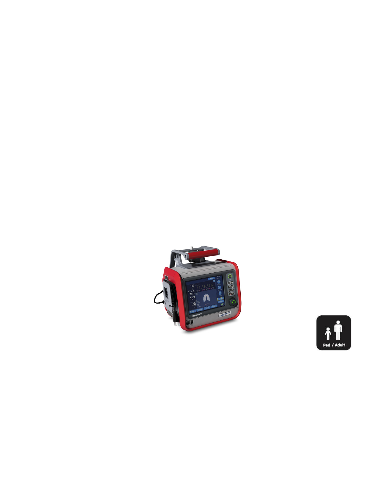
This Quick Guide is intended as a useful reference for ventilation of adult and pediatric patients.
It does not replace the clinical judgment of a physician or the content of the HAMILTON-T1
Operator’s Manual, which should always be available when using the HAMILTON-T1 ventilator.
Some functions are optional and not available in all markets.
© 2015 Hamilton Medical AG. All rights reserved. Printed in Switzerland.
Page 3

3
Hamilton Medical | HAMILTON-T1 Quick Guide
Table of contents
1. HAMILTON-T1 basics ................................................................................................................................ 4
2. Setting up the ventilator .......................................................................................................................... 10
3. Tests and calibrations .............................................................................................................................. 18
4. Ventilating a patient ................................................................................................................................ 22
5. Monitoring patient data ......................................................................................................................... 28
6. Ensuring an adequate oxygen supply for patient transport ...................................................................... 30
7. Glossary of control parameters .............................................................................................................. 32
Page 4
4
English | 624840/00
1. HAMILTON-T1 basics
1.1 Ventilator front view
Page 5

5
Hamilton Medical | HAMILTON-T1 Quick Guide
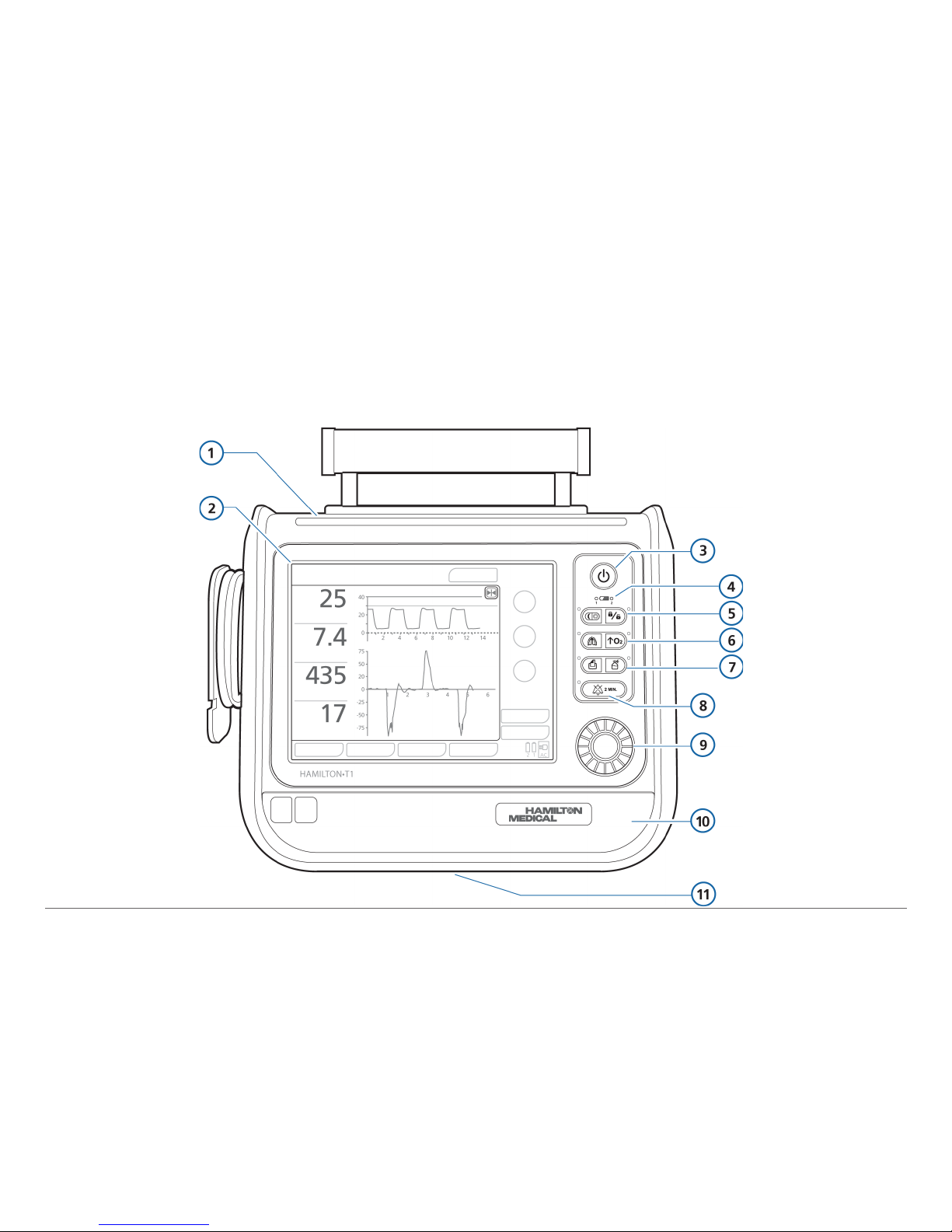
1 Alarm lamp. Red = high-priority alarm, yellow = medium- or low-priority alarm.
2 Touch screen. Provides access to measurements and controls.
3 Power/Standby key. Turns the ventilator on and off and accesses standby.
4 Battery charge indicator. Lit = battery is fully charged. Flashing = battery is charging.
5 Day/Night key. Switches between the Day and Night display brightness setting.
5 Screen lock/unlock key. Prevents inadvertent change of settings.
6 Manual breath/inspiratory hold key. Triggers a mandatory breath when pressed and
released during exhalation. Triggers an inspiratory hold when held down during any breath
phase. When active, the green indicator is lit.
6 O2 enrichment key. Delivers 100% oxygen for 2 min. Press the key a second time to
cancel. Press O2 key and disconnect patient to start a suctioning maneuver.
7 Print screen key. Save a JPG file of the current ventilator screen to a USB memory drive.
7 Nebulizer on/off key. Activates pneumatic nebulizer for 30 minutes or until pressed again
during the inspiration phase if high-pressure oxygen (HPO) is connected.
8 Alarm silence key. Silences the main ventilator audible alarm for 2 min. Press the key a
second time to cancel the alarm silence.
9 Press-and-turn (P&T) knob. Use to select and adjust ventilator settings.
10 Front cover and battery. The backup batteries are located inside the front cover.
11 Underside of ventilator. Expiratory valve bleed port. Do not obstruct.
Page 6
6
English | 624840/00
1.2 Ventilator side view, with gas connections
Page 7

7
Hamilton Medical | HAMILTON-T1 Quick Guide
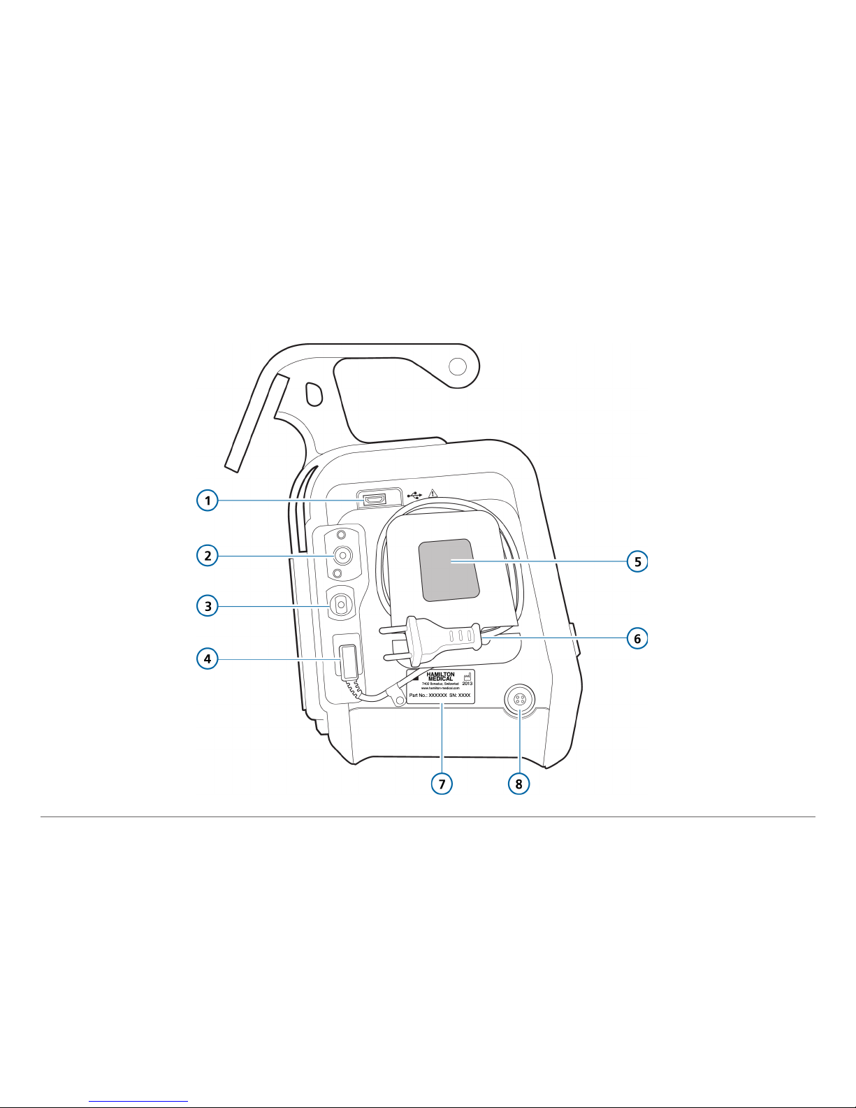
1 USB connector
2 High-pressure oxygen DISS or NIST inlet fitting
3 Low-pressure oxygen connector
4 AC power receptacle
5 Cooling air intake and dust filter. Do not obstruct.
6 AC power cord with retaining clip
7 Serial number label
8 DC power receptacle
Page 8
8
English | 624840/00
1.3 Main display
Page 9

9
Hamilton Medical | HAMILTON-T1 Quick Guide
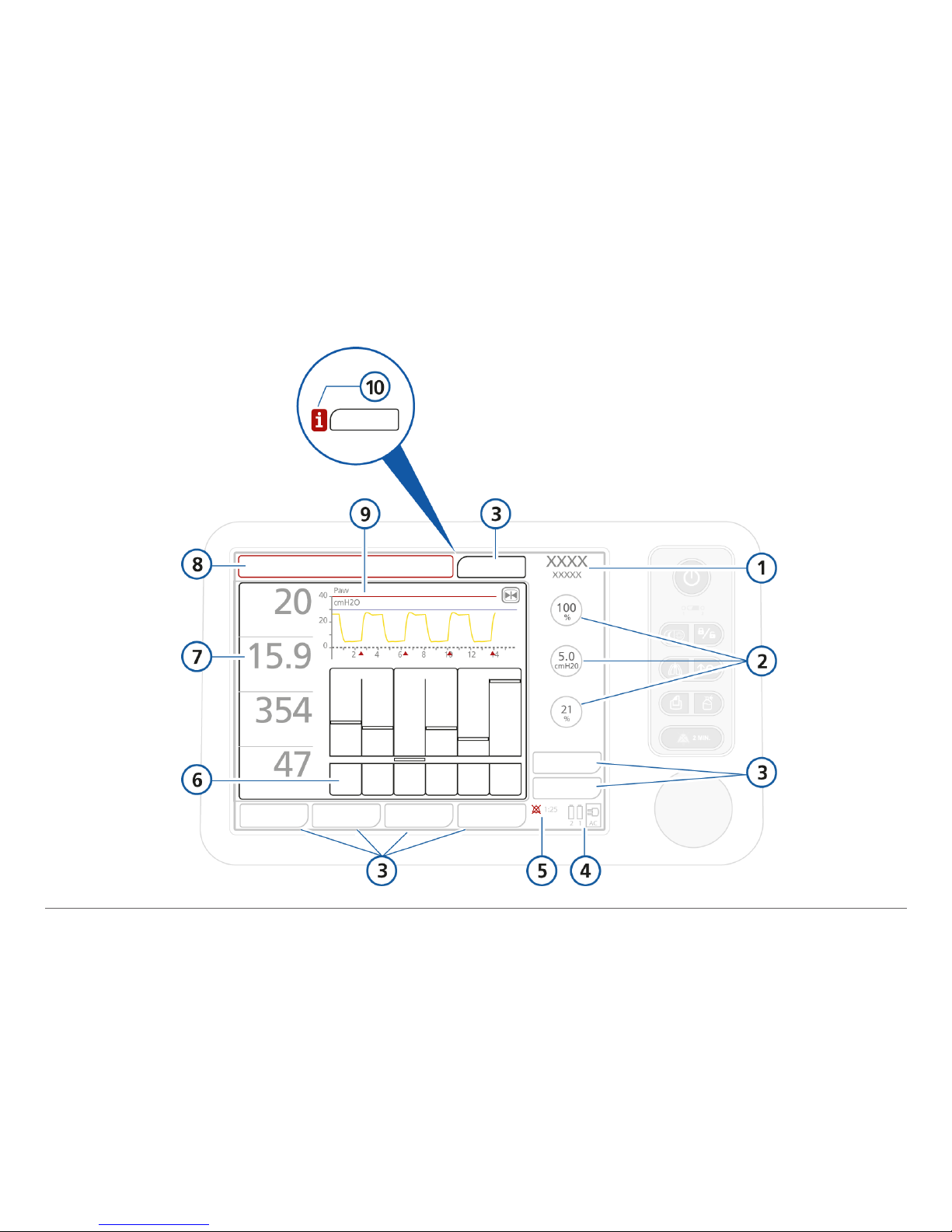
1 Active mode & patient group.
2 Main controls. Touch the Controls button (3) to display all controls for the selected mode.
3 Window tabs. Open the associated windows.
4 Input power. Shows available power sources.
5 Alarm silence indicator and countdown. Shows whether alarm silence has been activated,
and displays the remaining silence time.
6 Graphic display. Shows a user-selectable waveform or an Intelligent Panel graphic
(Dynamic Lung, ASV graph, Vent Status).
7 Main monitoring parameters (MMP). View other numeric parameters from the monitored
parameter windows.
8 Message bar. Displays color-coded alarm messages. If an alarm is active, view the alarm
buffer by touching the message bar.
9 Pressure/time waveform. Always displayed.
The red line is the Pmax high pressure alarm setting.
The blue line is the pressure limit automatically 10 cmH2O below the Pmax alarm
setting.
The pink triangles indicate the patient is triggering a breath.
The
Freeze button freezes the graphic for up to 30 s.
10 Alarm indicator (i-icon). Touch the icon to view information about alarms.
Page 10
10
English | 624840/00
2. Setting up the ventilator
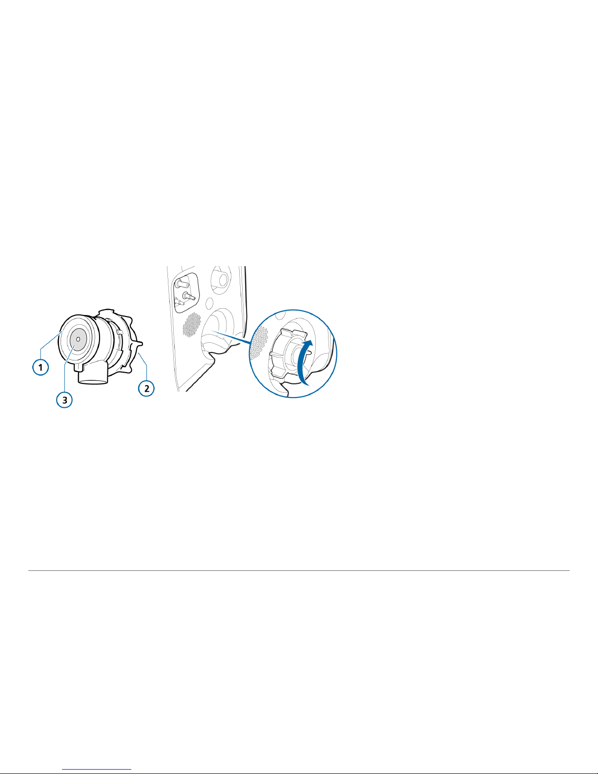
1 Expiratory valve membrane
2 Expiratory valve housing
3 Metal plate facing the ventilator
Installing the expiratory valve
1
Holding the expiratory valve housing, seat the silicone membrane onto the housing.
The metal plate must face up and be visible.
2 Position the housing and twist clockwise until it locks into place.
Single use and autoclavable expiratory valves are available.
Page 11
11
Hamilton Medical | HAMILTON-T1 Quick Guide
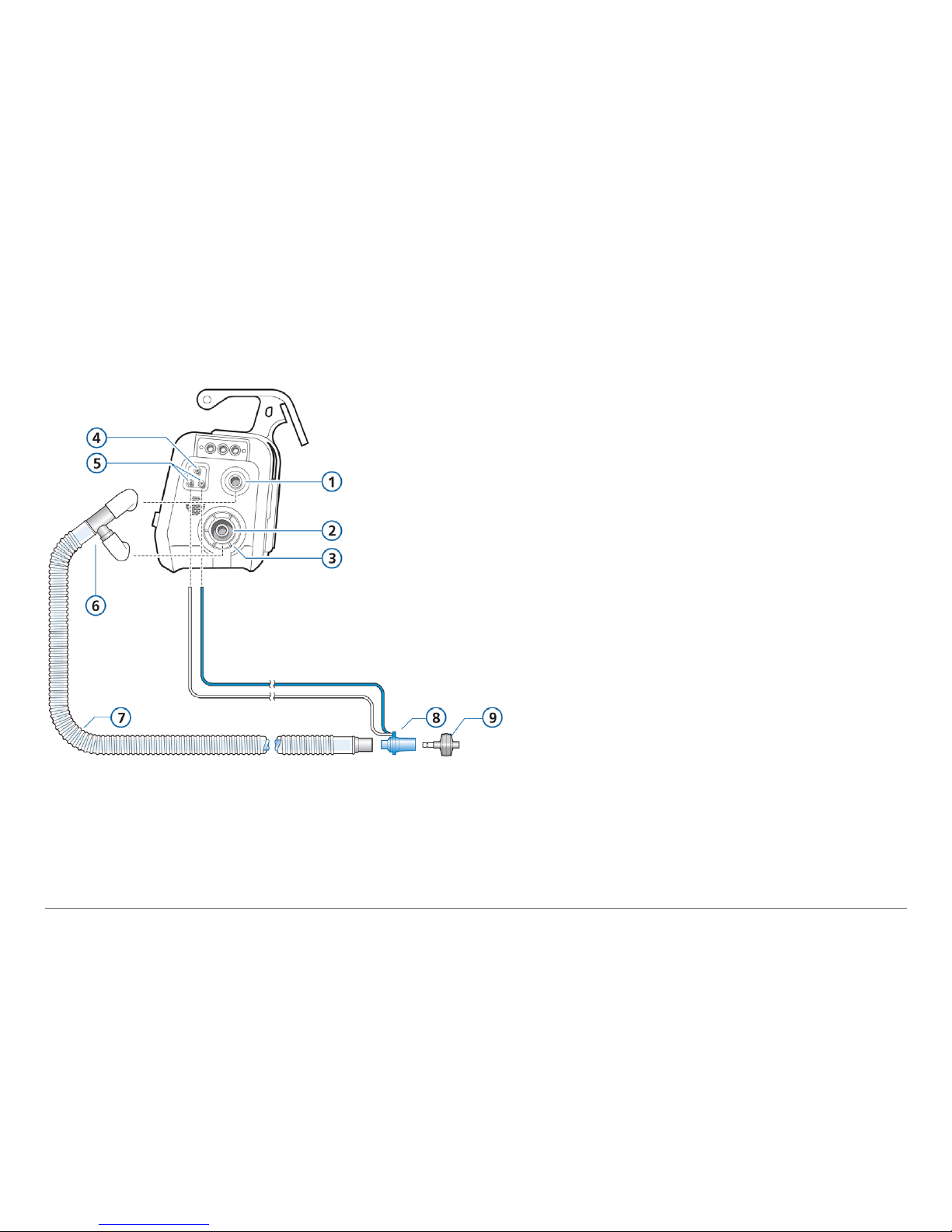
2.2 Connecting a coaxial breathing circuit
1 To patient (inspiratory port)
2 From patient (expiratory port)
3 Adult/pediatric expiratory valve set
4 Nebulizer outlet
5 Flow sensor connectors
6 Limb connector
7 Coaxial inspiratory/expiratory limb
8 Flow sensor
9 HMEF
Connect the breathing circuit to the
inspiratory and expiratory ports
(1, 2) and
the flow sensor tubes to the flow sensor
connectors
(5).
Use either a bacteria filter or a combined
heat-moisture exchanger and filter (HMEF).
Page 12
12
English | 624840/00
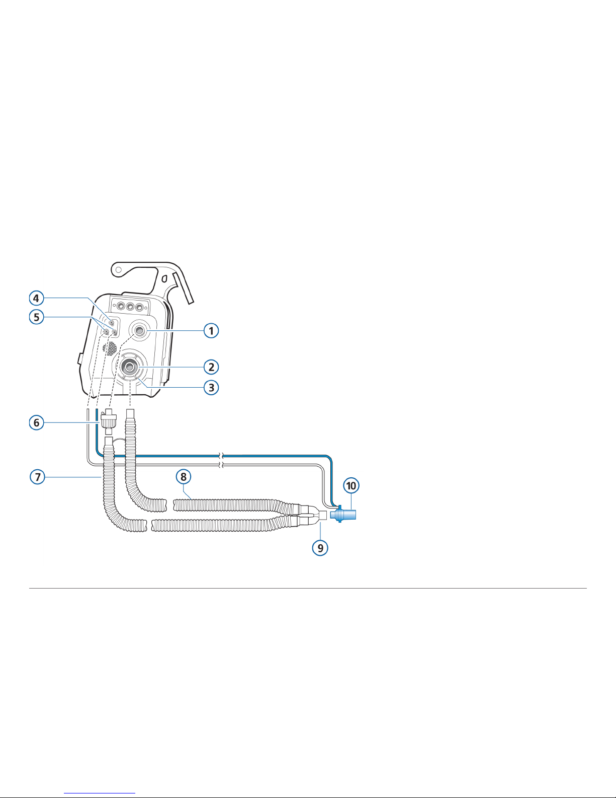
2.3 Connecting a dual limb circuit
1 To patient (inspiratory port)
2 From patient (expiratory port)
3 Adult/pediatric expiratory valve set
4 Nebulizer outlet
5 Flow sensor connectors
6 Bacteria filter
7 Inspiratory limb
8 Expiratory limb
9 Y-piece (integrated with breathing
circuit)
10 Flow sensor
Use either a bacteria filter or a combined
heat-moisture exchanger and filter
(HMEF).
Page 13
13
Hamilton Medical | HAMILTON-T1 Quick Guide
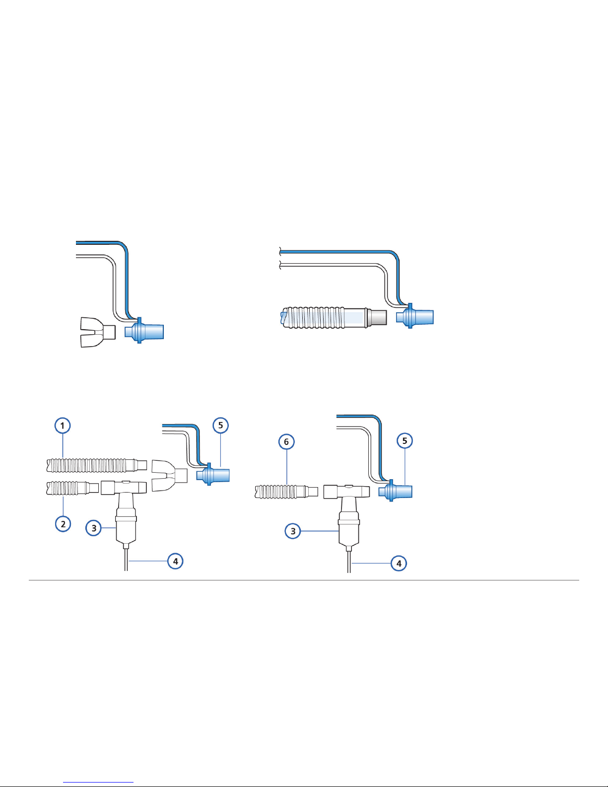
2.4 Connecting an adult/pediatric ow sensor
2.5 Connecting the internal pneumatic nebulizer
1 Expiratory limb
2 Inspiratory limb
3 Nebulizer
4 Tube
5 Flow sensor
6 Coaxial breathing
circuit
Page 14
14
English | 624840/00
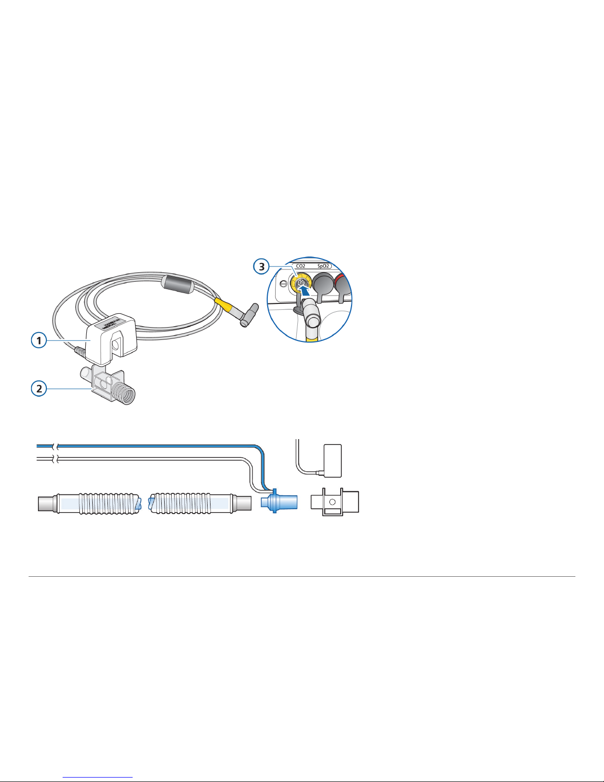
2.6 Connecting a CO2 mainstream sensor
Attaching the CO2 sensor to the
airway adapter
1 CO2 sensor
2 Airway adapter
3 Connect to CO2 port on
ventilator
Connecting the CO2 sensor/
adapter to the patient circuit
You can connect the CO2 sensor
before or after the ow sensor
according to your institution’s
protocol.
Page 15
15
Hamilton Medical | HAMILTON-T1 Quick Guide
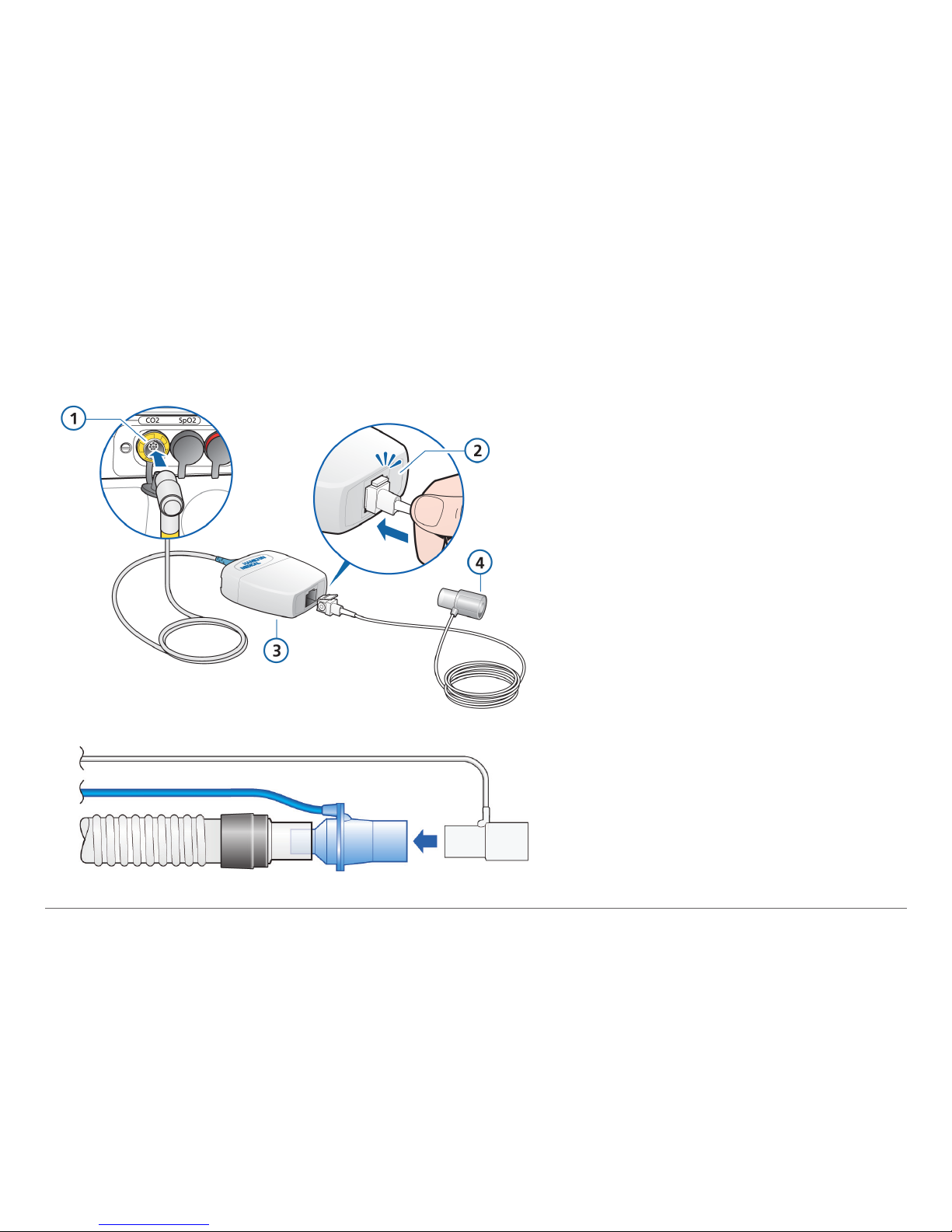
2.7 Connecting a CO2 sidestream sensor
Inserting the sample cell into the
CO2 module
1 Connect to CO2 port on ventilator
2 Sample cell clicks into place
3 LoFlow sidestream CO2 module
4 Airway adapter
Attaching the CO2 sensor to the
airway
Page 16
16
English | 624840/00
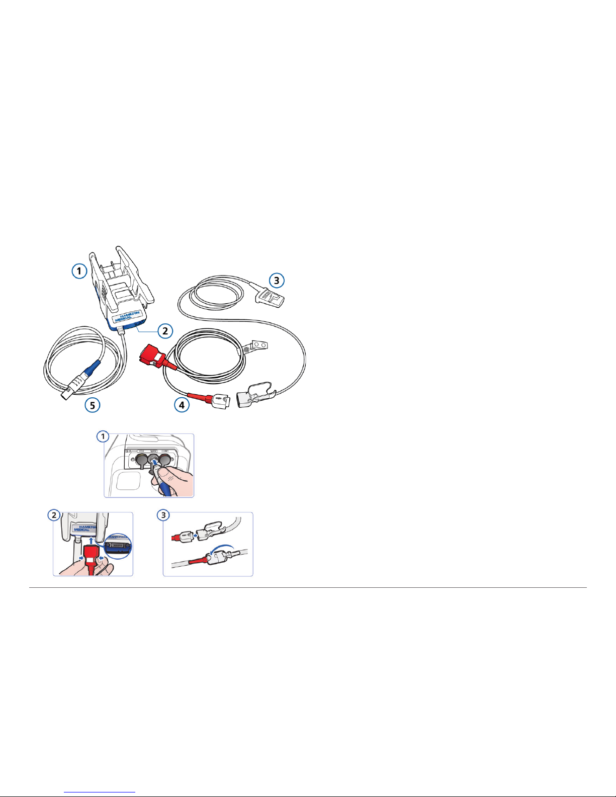
2.8 Connecting an SpO2 monitor
Masimo SET pulse oximeter components
1 Adapter, which contains the oximeter
hardware
2 Cable connection ports
3 Sensor and cable
4 Patient cable (connects to adapter and
sensor)
5 Adapter cable (connects the adapter to
SpO2 connector on ventilator)
Connecting the cables
Connect the ventilator, patient, and
sensor cables as shown.
Not all options are available in all markets.
Page 17
17
Hamilton Medical | HAMILTON-T1 Quick Guide
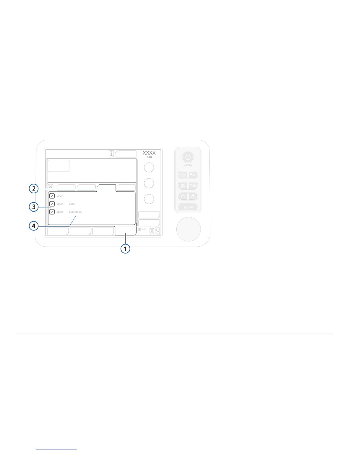
2.9 Enabling CO2/SpO2 monitoring
To enable CO2 / SpO2 monitoring
1
Open the System > Sensors on/off window.
2 Select the CO2 and/or SpO2 checkboxes, and close the window.
The status text Acve appears next to the checkbox as long as the adapter is connected
to the ventilator. If the status area is empty, the adapter is not connected.
1 System
2 Sensors on/off
3 CO2 and SpO2
4 Sensor status
Page 18
18
English | 624840/00
3. Tests and calibrations
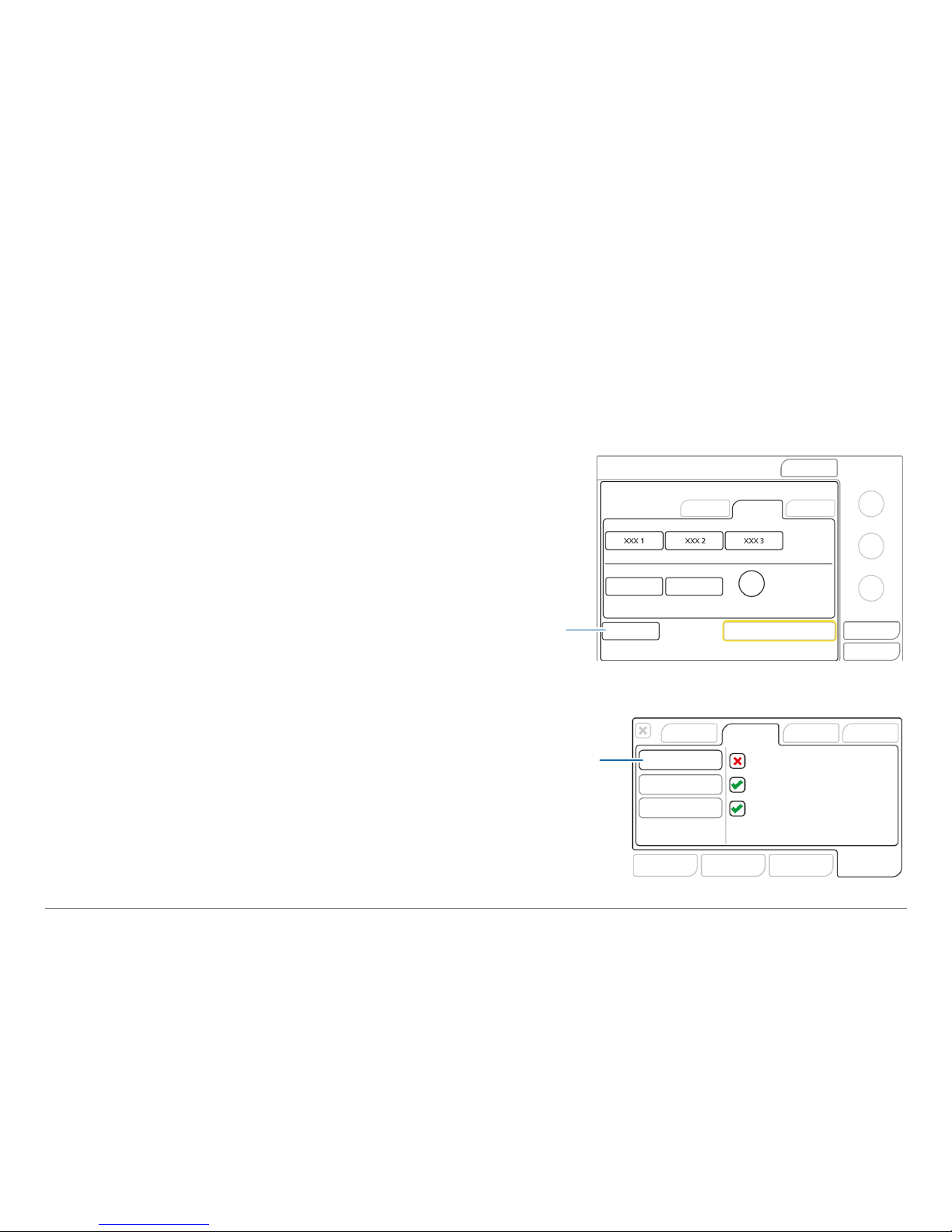
Step one
1
Touch Preop check in the Standby window.
The System > Tests & calib window is displayed.
2 Touch the Tightness button to perform the
tightness test.
1 Connect ventilator to AC or DC power and an
oxygen supply.
2 Assemble the patient breathing circuit.
3 Turn on power.
The ventilator runs a self-test and displays the
Standby window. Use only if ventilator passes all
tests.
3.1 Performing the preoperational checks
Preop
check
Tightness
Page 19
19
Hamilton Medical | HAMILTON-T1 Quick Guide
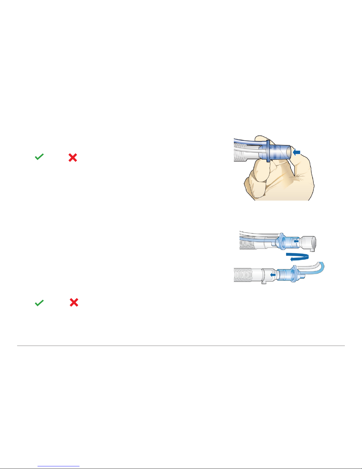
4 When prompted, block the patient end of the
breathing circuit. Hold until prompted.
Pass or fail and date/time of completed test
are displayed.
Step two
1
Touch the Flow Sensor button to calibrate the
flow sensor.
2 When prompted, turn the flow sensor and con-
nect to Y-piece using the calibration adapter.
Calibration starts automatically.
3 When prompted, turn the flow sensor again and
remove the calibration adapter.
Calibration starts automatically.
Pass
or fail and date/time of completed test
are displayed.
Page 20

20
English | 624840/00
Step three
1
If necessary, and if prompted by next to the O2 test button, perform the O2 sensor
calibration.
2 Touch the O2 test button.
If O2 cell calibration needed alarm is active, repeat O2 calibration once device has warmed up
(after 30 minutes).
Step four
To demonstrate the alarm’s operation, perform an alarm test.
Loss of external power test
1
Ensure the ventilator is connected to AC power.
2 Disconnect the power cord.
3 Verify that the Loss of external power alarm is generated and that the ventilator is powered by
its backup battery.
4 Reconnect the ventilator to AC power.
5 Verify that the alarm resets and that the ventilator is again powered by AC.
The HAMILTON-T1 is ready to ventilate
.
Page 21
21
Hamilton Medical | HAMILTON-T1 Quick Guide
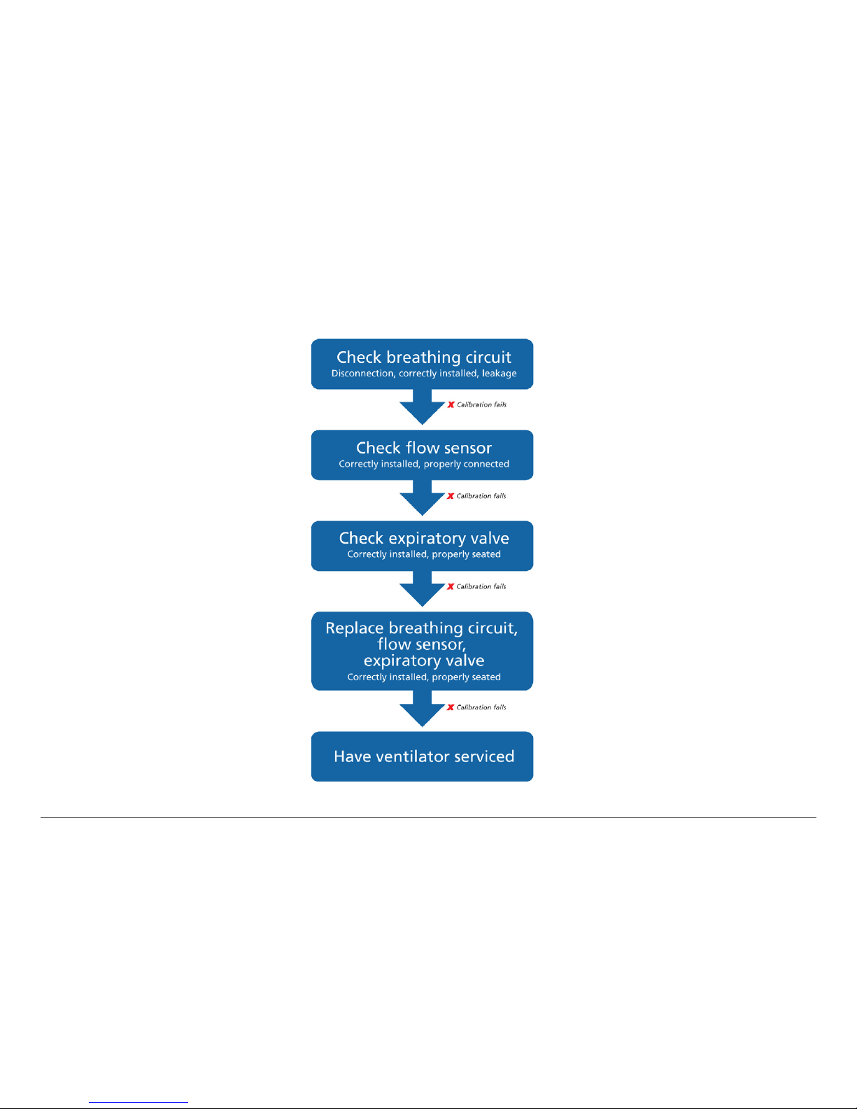
3.2 If the preoperational check fails
Page 22
22
English | 624840/00
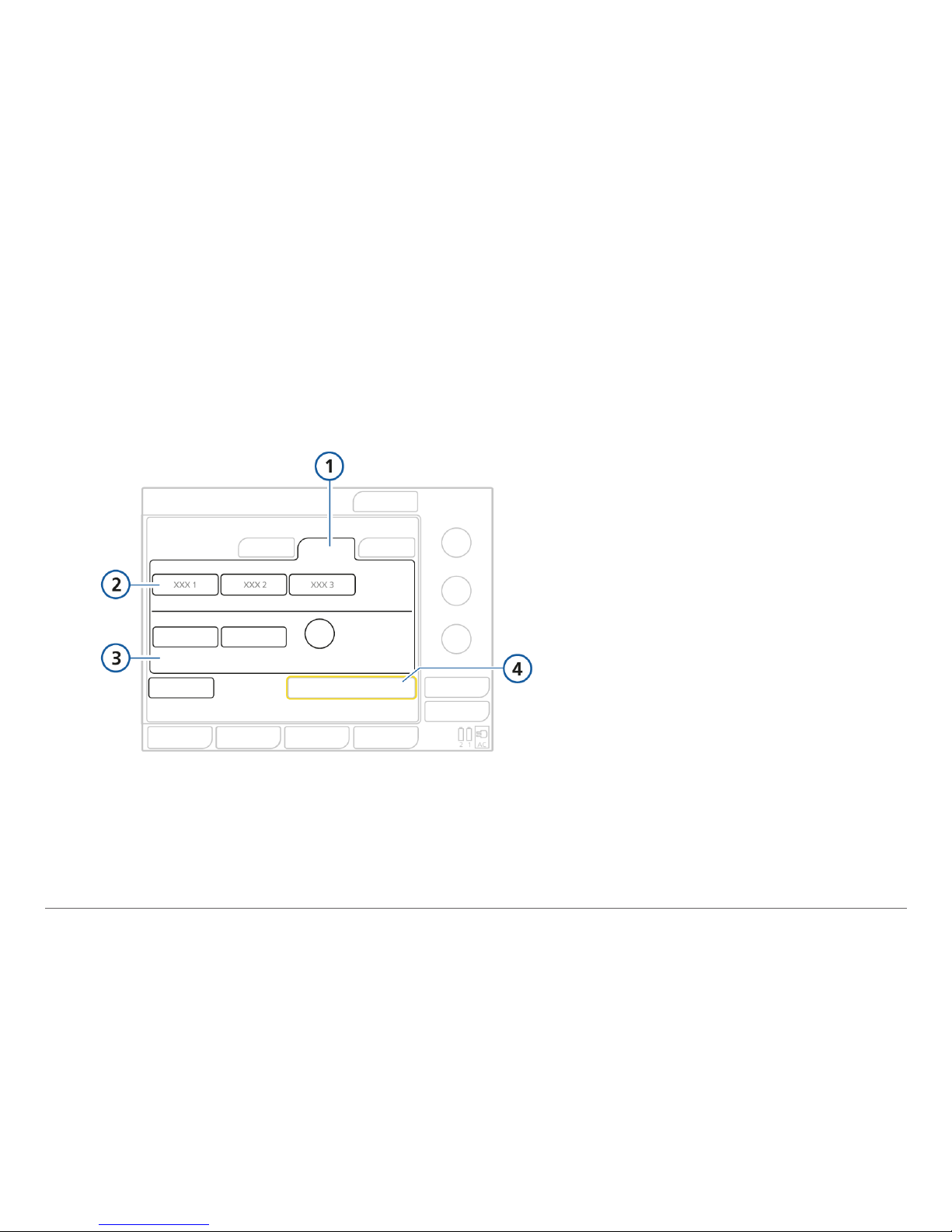
4. Ventilating a patient
1 Patient group
2 Quick Setup buttons
3 Gender and patient
height
4 Start ventilation
4.1 Using Quick Setup
A Quick setup refers to a group of settings you dene, including patient characteristics (group
and weight), mode selection and some control settings, alarm limit settings, and weaning zone
limits, that is automatically applied when the setup is selected in the Standby window.
Page 23

23
Hamilton Medical | HAMILTON-T1 Quick Guide
The HAMILTON-T1 has three congurable Quick Setup buttons.
Settings can be congured in advance according to your institution’s standard protocols.
Once congured, you can start ventilation in six easy steps.
1 Touch one of the three Quick Setup buttons.
2 Touch Male or Female.
3 Touch Pat. Height and adjust patient height using the Press-and-Turn knob.
The ventilator uses patient height and gender to calculate the ideal body weight (IBW). IBW is
used to determine several startup settings (see page25).
4 If required, touch Modes tab to change ventilation mode.
5 Review control and alarm settings.
6 Touch Start ventilation.
Page 24
24
English | 624840/00
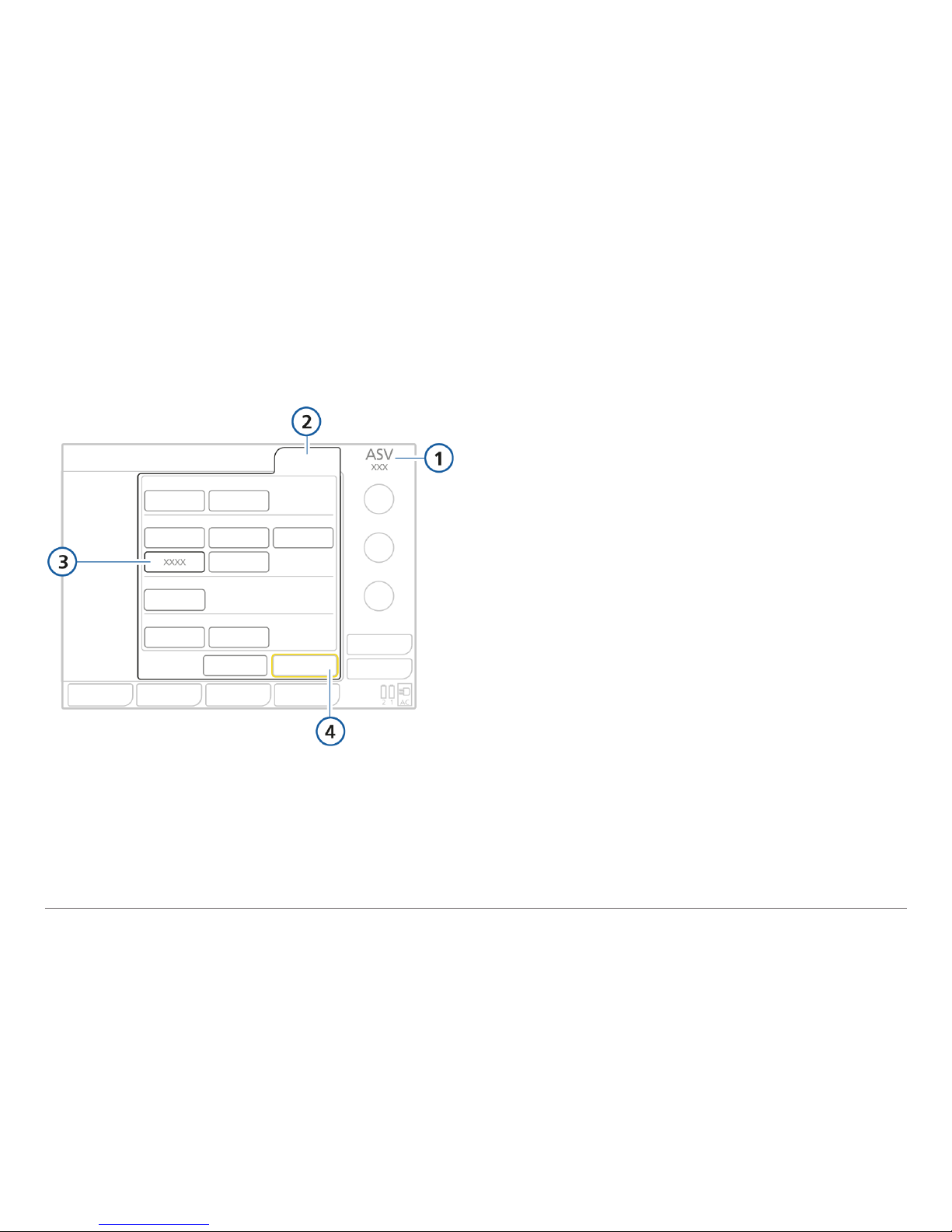
4.2 Selecting modes
1 Active mode
2 Modes
3 New mode to apply
4 Confirm
To change the mode
1
Select the desired ventilation mode.
2 Touch Confirm.
The Controls window opens.
Page 25
25
Hamilton Medical | HAMILTON-T1 Quick Guide
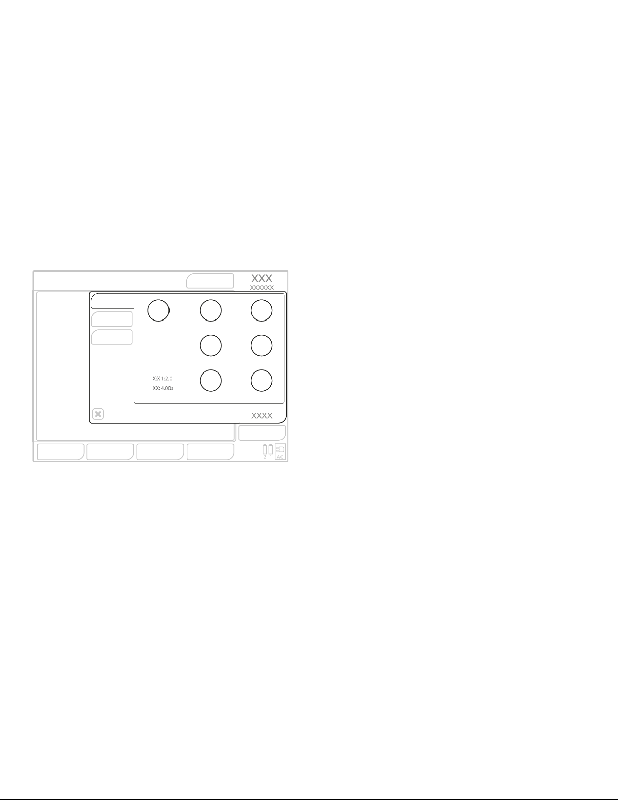
4.3 Adjusting controls
To adjust controls
1
Touch the control to adjust.
The control button turns orange.
2 Use the P&T knob to change to the
desired setting.
3 Confirm changes to the setting by touch-
ing the control again or by pressing the
P&T knob.
The control button turns blue.
Confirm changes before modifying
another control.
The following parameters are set based on ideal body weight (IBW): Vt, Rate, Thigh, Tlow, TI,
ExpMinVol, and Vt alarm limits. The ventilator uses the Vt/IBW setting to set the initial delivered Vt
in volume-controlled modes.
See glossary of control parameters on page 32.
Page 26
26
English | 624840/00
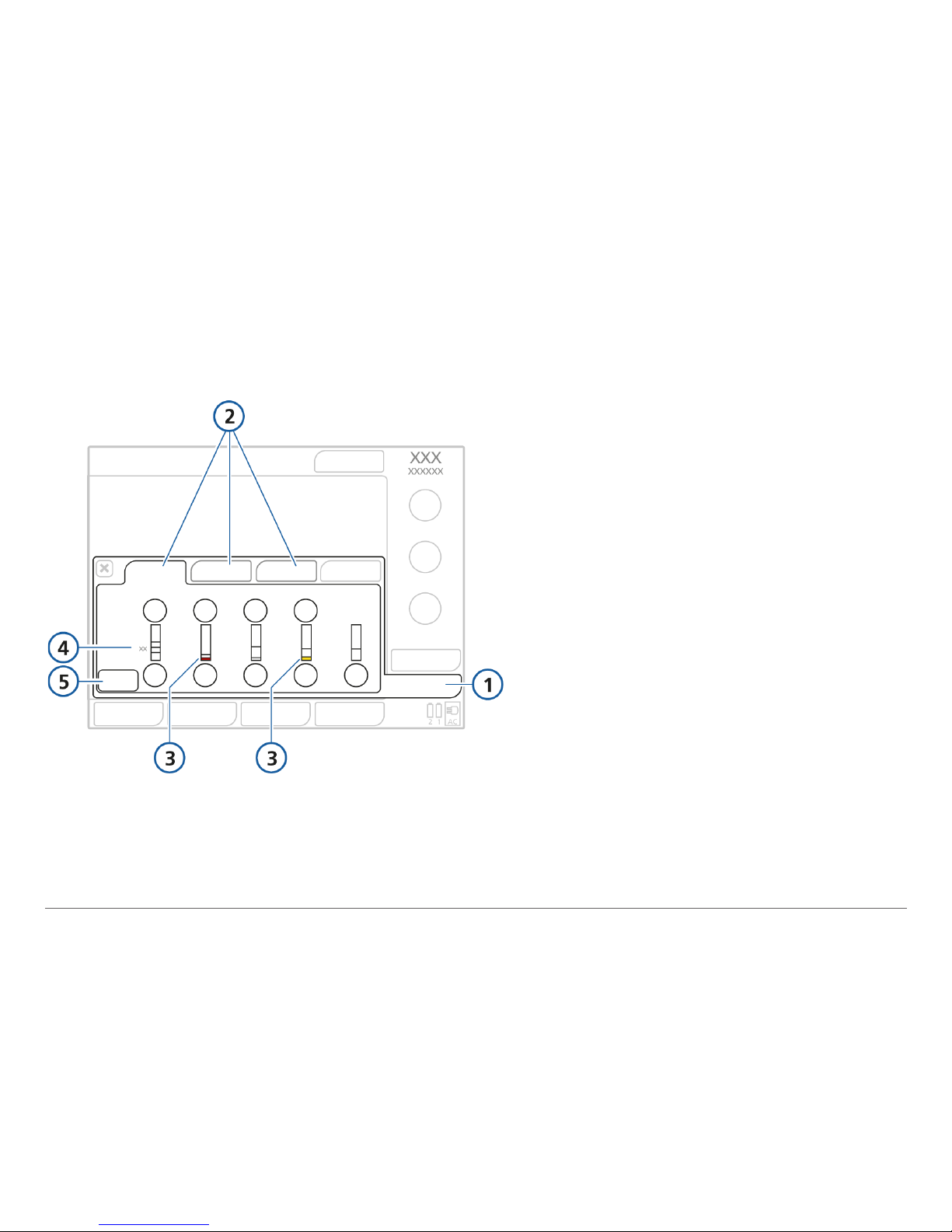
4.4 Adjusting alarm limits
1 Alarms
2 Limits 1, 2, 3
3 Red or yellow bar (depending on
alarm priority) indicates the monitored value is out of range
4 Current monitored value
5 Auto button
Changing the High pressure and VT high
alarm settings may affect ventilation.
See next page.
Page 27
27
Hamilton Medical | HAMILTON-T1 Quick Guide
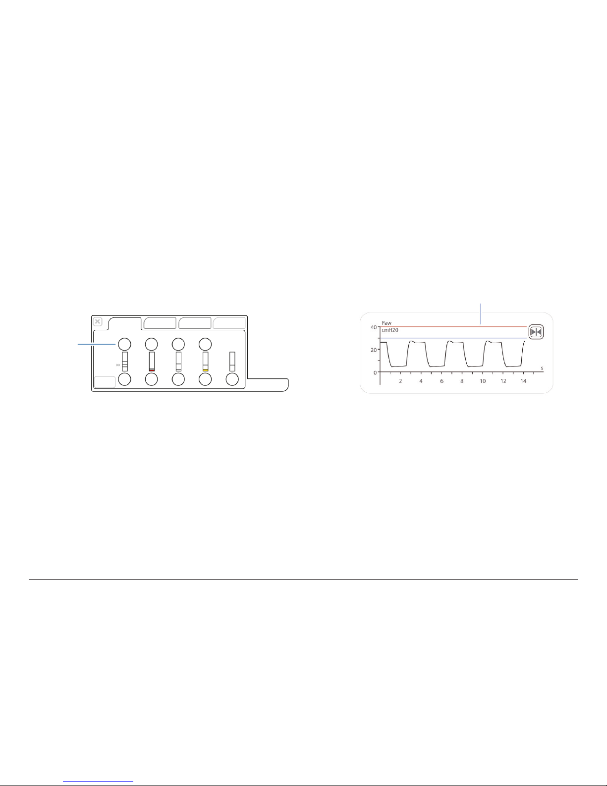
High pressure alarm
The High pressure alarm sets the pressure limit 10 cmH2O below the Pmax setting. Changing the
VT high alarm
Inspiratory volume is limited to 1.5 times the set VT high alarm limit. Changing the VT high alarm
may limit the inspiratory volume. Volume limitation is disabled in NIV modes.
Pressure
high alarm
limit
Pressure high alarm limit
Page 28
28
English | 624840/00
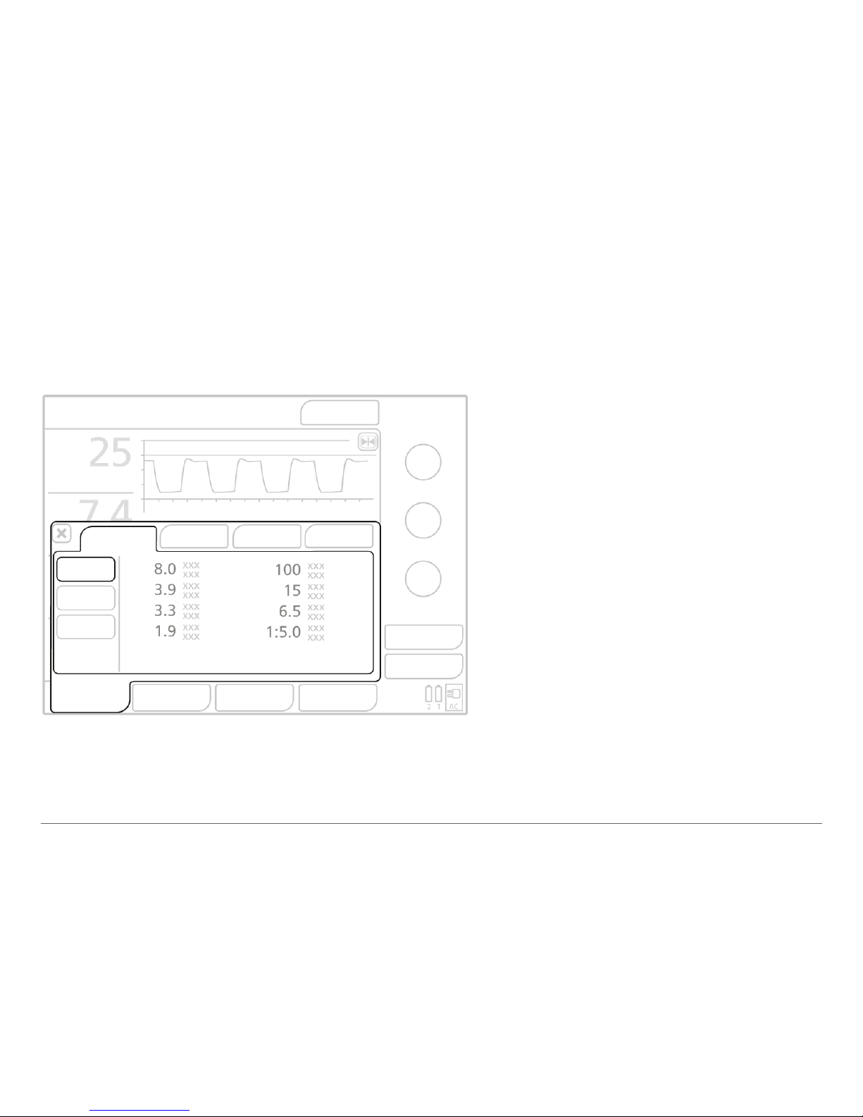
5. Monitoring patient data
Touch the Monitoring button to
access patient data.
Page 29
29
Hamilton Medical | HAMILTON-T1 Quick Guide
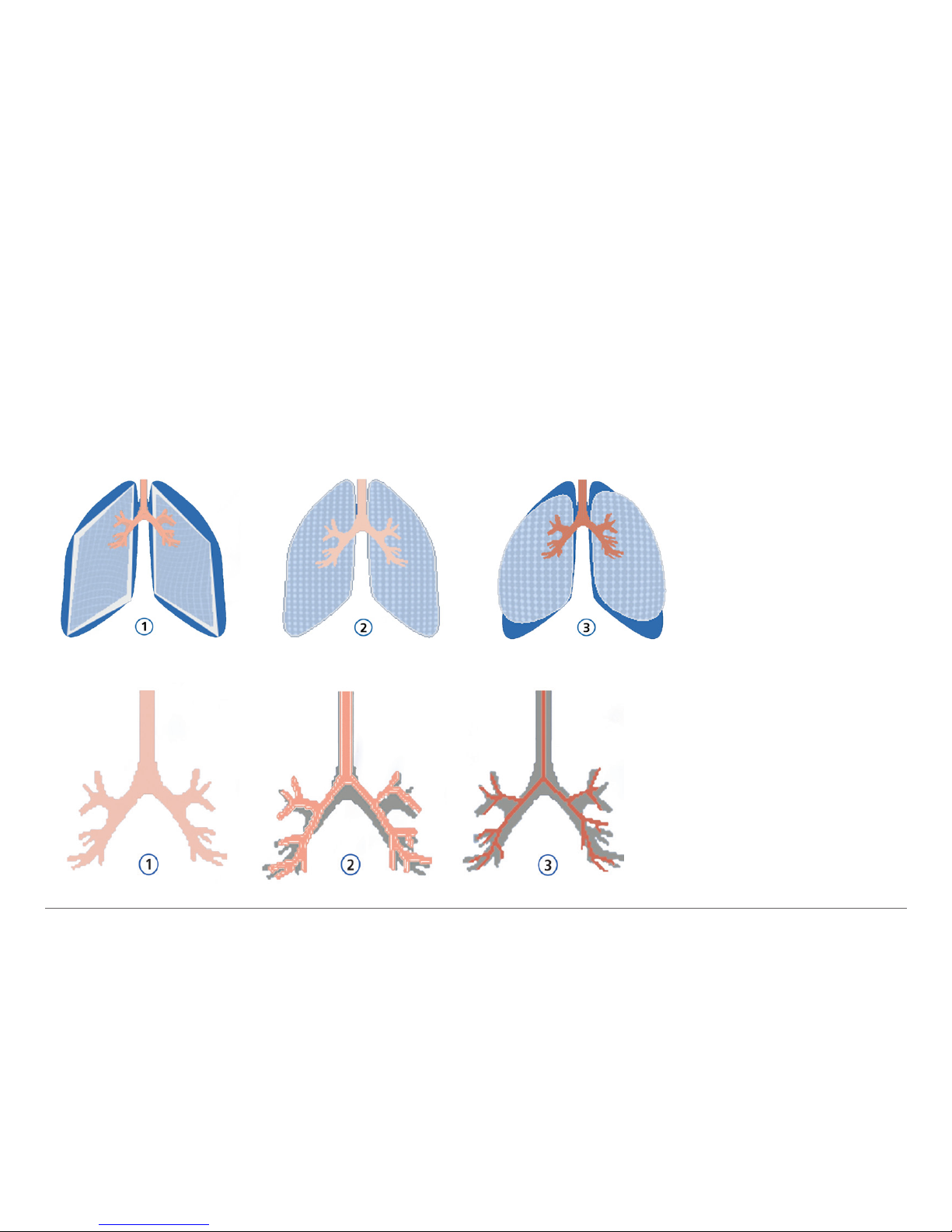
5.1 Monitoring patient data using the dynamic lung
The dynamic lung shows compliance (Cstat) and resistance (Rinsp) breath-by-breath relative to
“normal” values for the patient’s height.
1 Low compliance
2 Normal compliance
3 High compliance
1 Normal resistance
2 Moderately high
resistance
3 High resistance
Page 30

30
English | 624840/00
6. Ensuring an adequate oxygen supply for patient transport
Before transporting a patient, ensure an adequate oxygen supply by checking the O2 consumpon
parameter. During ventilation the current oxygen consumption rate is displayed in the O2 con-
sumpon parameter (l/min) in the System > Info window.
The oxygen consumption of a nebulizer attached to the device is not included in the O2 consump-
on parameter value.
O2 consumpon
Page 31

31
Hamilton Medical | HAMILTON-T1 Quick Guide
6.1 Estimating O2 consumption for transport
Prior to transport you can estimate the patient’s O2 consumption.
For smaller patients, ≤ 70 cm, IBW ≤ 8 kg
O2 consumption = [(ExpMinVol * 2) + 3 l/min] * (FiO2 – 20.9) / 79.1
For larger patients, > 70 cm, IBW > 8 kg
O2 consumption = (ExpMinVol + 3 l/min) * (FiO2 – 20.9) / 79.1
Additional amount for the nebulizer oxygen use
Nebulizer O2 consumption = 8 l/min * Insp time/total breath time
Page 32

32
English | 624840/00
7. Glossary of control parameters
Parameter Denition
Apnea Backup A function that provides ventilation after the adjustable apnea time passes without breath attempts. If “Automatic”
is enabled, control parameters are calculated based on the patient‘s IBW.
ETS Expiratory trigger sensitivity. The percentage of peak inspiratory ow at which the ventilator cycles from inspiration
to exhalation.
Flow trigger The patient’s inspiratory ow that triggers the ventilator to deliver a breath.
Gender Sex of patient. Used to compute ideal body weight (IBW) for adults and pediatrics.
I:E Ratio of inspiratory time to expiratory time. Applies to mandatory breaths.
%MinVol Percentage of minute volume to be delivered in ASV mode. The ventilator uses the %MinVol, Pat. height, and Gender
settings to calculate the target minute ventilation.
Oxygen Oxygen concentration to be delivered.
Pasvlimit The maximum pressure to apply in ASV mode. Changing Pasvlimit or the Pressure alarm limit automatically changes
the other: The Pressure alarm limit is always 10 cmH2O greater than Pasvlimit.
Pat. height Patient height. It determines the ideal body weight (IBW), which is used in calculations for ASV and startup settings
for adult and pediatric patients.
Page 33

33
Hamilton Medical | HAMILTON-T1 Quick Guide
Glossary of control parameters
Parameter Denition
Pcontrol
The pressure additional to PEEP/CPAP.
PEEP/CPAP
Positive end expiratory pressure.
P high
The high pressure setting in APRV and DuoPAP modes. Absolute pressure, including PEEP.
Pinsp Pressure (additional to PEEP/CPAP) to apply during the inspiratory phase. Applies in PSIMV+ IntelliSync and NIV-ST.
P low The low pressure setting in APRV.
P-ramp Pressure ramp. Time required for inspiratory pressure to rise to the set (target) pressure.
Psupport Pressure support for spontaneous breaths in SPONT, NIV, and SIMV+ modes.
Rate Respiratory frequency or number of breaths per minute.
Sigh Breaths delivered at a regular interval (every 50 breaths) at a pressure up to 10 cmH2O higher than non-sigh breaths,
as allowed by the Pressure alarm limit.
Page 34

34
English | 624840/00
Glossary of control parameters
Parameter Denition
Thigh Length of time at the higher pressure level, P high, in DuoPAP and APRV modes.
TI Inspiratory time, the time to deliver the required gas (time to reach the operator-set Vt or Pcontrol value).
Used with Rate to set the breath cycle time.
TI max Maximum inspiratory time for ow-cycled breaths in NIV, NIV-ST, and SPONT in neonatal modes.
T low Length of time at the lower pressure level, P low, in APRV mode.
Vt Tidal volume delivered during inspiration in (S)CMV+ and SIMV+ modes.
VT/kg Tidal volume per weight.
Page 35

Page 36

Manufacturer:
Hamilton Medical AG
Via Crusch 8, 7402 Bonaduz, Switzerland
+41 58 610 10 20
[email protected]
www.hamilton-medical.com
PN 624840/00
 Loading...