


HAMAMATSU F2813-21S, F2813-21M, F2813-21, F2813-13P, F2813-13M Datasheet
...
RECTANGULAR MCP AND ASSEMBLY SERIES
A microchannel plate (MCP) is a secondary electron multiplier consisting of an array of glass capillaries (channels) fused into the form of a thin plate. Each channel has an internal diameter of 6 µm to 25 µm and works as an independent electron multiplier, making possible the detection and amplification of two-dimensional information.
In addition to previously available circular-type MCPs, Hamamatsu has available seven types of rectangular MCPs. Of these, three standard types include demountable assemblies which have electrode leads and read-out devices. Using these, it is possible to alleviate dimensional limitations encountered when building the MCPs into instruments as compared with circular types, greatly facilitating the effective use of these devices. The demountable assembly can be selected as combinations of MCPs (1 to 3 stage) and a read-out device (singleanode, multi-anode or phosphor screen). Making possible the selection of the most suitable configuration for your application, while facilitating replacement as well.
FEATURES
•Convenience of use due to fewer leads
•Choice and interchangeability of MCP and read-out devices
•High gain and low noise
•Two-dimensional image intensification
•Fast time response
•Immunity to magnetic fields
•Sensitive to electrons, ions, VUV lights, X-rays and
γ-rays
•Stable in air
•Low power consumption
•Small size and light weight
•Can be baked in vacuum at up to 350°C
APPLICATIONS
Detection and imaging of electrons, ions, VUV lights, X-rays and γ-rays
•Mass spectroscopy
•Energy spectroscopy
•High-speed response CRTs
Subject to local technical requirements and regulations, availability of products included in this promotional material may vary. Please consult with our sales office.
Information furnished by HAMAMATSU is believed to be reliable. However, no responsibility is assumed for possible inaccuracies or omissions. Specifications are subjected to change without notice. No patent rights are granted to any of the circuits described herein. © 1999 Hamamatsu Photonics K. K.
RECTANGULAR MCP AND ASSEMBLY SERIES
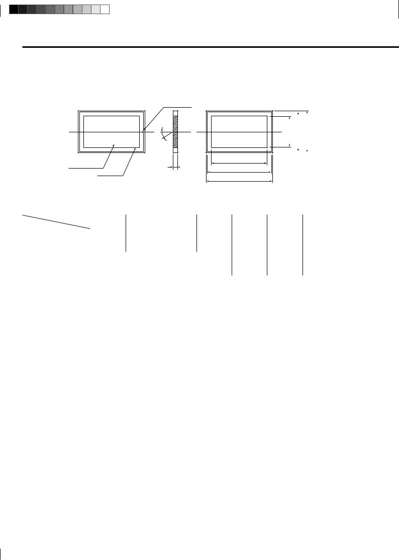
MCP DIMENSIONAL OUTLINES (Unit: mm)
INPUT SIDE |
INDICATOR A |
OUTPUT SIDE |
|
|
|
|
θ |
|
C
EFFECTIVE AREA
D |
|
B |
ELECTRODE
A
C’ |
|
B’ |
|
A’ |
|
|
|
|
|||
|
|
|
|
|
|
|
|
|
|
|
|
|
|
|
|
|
|
|
|
|
|
|
|
|
|
|
|
TMCPA0028EB |
|
|
|
|
|
|
|
|
|
|
|
Type |
F6492 |
F2370-01 |
|
F4772-01 |
F2806-01 |
F1943-02 |
F2805-03 |
F2396-04 |
Unit |
|
Parameters |
|
|||||||||
|
|
|
|
|
|
|
|
|
|
|
Outer dimensions A × A’ |
139.9 × 8.9 |
15.9 × 9.4 |
|
61.9 × 13.9 |
49.9 × 39.9 |
|
87.9 × 37.9 |
59.9 × 59.9 |
96.9 × 78.9 |
mm |
Electrode dimensions B × B’ |
138 × 8 |
15 × 8.5 |
|
61 × 9.4 |
49 × 39 |
|
87 × 37 |
58 × 58 |
95.6 × 77.3 |
mm |
MCP Effective dimensions C × C’ |
127 × 4 |
13 × 6.5 |
|
55 × 8 |
45 × 35 |
|
81 × 31 |
53 × 53 |
90 × 72 |
mm |
Thickness D |
|
|
0.48 |
|
|
0.60 |
0.80 |
1.00 |
mm |
|
|
|
|
|
|
|
|
|
|
|
|
Channel diameter |
|
|
12 |
|
|
15 |
20 |
25 |
m |
|
Channel pitch |
|
|
15 |
|
|
19 |
25 |
31 |
m |
|
Bias angle θ |
|
|
|
|
8 |
|
|
|
|
degrees |
Open area ratio |
|
|
|
|
60 |
|
|
|
|
% |
Electrode material |
|
|
|
|
Inconel |
|
|
|
– |
|
|
|
|
|
|
|
|
|
|
|
|
ELECTRICAL CHARACTERISTICS |
|
|
|
|
|
|
||||
(Supply Voltage: 1000 V, Vacuum: 1.3 × 10⁻⁴ Pa (1 × 10⁻⁶ Torr), Ambient Temperature: 25 °C) |
|
|
|
|||||||
|
|
|
|
|
|
|
|
|
|
|
Current Gain |
|
|
|
|
More than 104 |
|
|
|
— |
|
Plate Resistance |
10 to 100 |
100 to 500 |
|
20 to 200 |
|
20 to 120 |
10 to 50 |
MΩ |
||
Dark Current |
|
|
|
|
Less than 5 × 10-13 |
|
|
|
A/cm2 |
|
Max. Linear Output Signal |
|
|
|
Up to 7% of the strip current B |
|
|
– |
|||
MAXIMUM RATINGS |
|
|
|
|
|
|
|
|
|
|
|
|
|
|
|
|
|
|
|
||
Supply Voltage C |
|
|
1000 |
|
|
1100 |
1200 |
V |
||
Ambient Temperature |
|
|
|
–50 to + 70 |
|
|
–50 to +50 |
°C |
||
AThis indicator shows the MCP input side and the direction of channel bias.
The F2806-01 has bias angle of opposite direction against the perpendicular line shown in the figure.
BThe strip current is the current which flows along the channel wall when a voltage is supplied between the MCP input and output and is given by Supply voltage/Plate resistance.
C At a vacuum of 1.3 × 10⁻⁴ Pa (1 × 10⁻⁶ Torr) or less.
Comment: Consult us for other dimensions, details on MCP resistance ranges and other information.
MCP-Assembly_2E.pm6 |
1 |
|
|
||
|
|
|
 Loading...