

Page 1

International Assembly Instructions for model MF110
ENGLISH
ESPAÑOL DEUTSCH FRANÇAIS ITALIANO PYCCKO
Spanish German French Italian Russian Japanese Mandarin
Sanus Systems 2221 Hwy 36 West, Saint Paul, MN 55113 5.10.06
Customer Service: (800) 359-5520 • (651) 484-7988 • fax (651) 636-0367
Customer Service Europe: 31 (0)20 5708938 • fax 31 (0)20 5708989
See complementary Sanus products at www.sanus.com
中文
Page 2

Page 3

Assembly Instructions for Model: MF110
Thank you for choosing a Sanus Systems VisionMount™ wall mount. The MF110 is designed to mount LCD at panels with VESA
(Video Electronics Standards Association) hole pattern up to 200mm x 200mm and weighing up to 100 lb [45.5 Kg] to a vertical wall. It will
allow the television to be pulled out 9.5” [241.3 mm] from of the wall. It will allow you to swivel the television ±30° (may vary with size of
television), tilt +5° to -15°, and have a ±6° roll control.
WARNING: If you do not understand these directions, or have any doubts about the safety of the installation, please call a qualied
contractor or contact Sanus at 800.359.5520 or www.sanus.com. Check carefully to make sure that there are no missing or defective
parts. Our customer service representatives can quickly assist you with installation questions and missing or damaged parts. Replacement
parts for products purchased through authorized dealers will be shipped directly to you. Never use defective parts. Improper installation
may cause damage or serious injury. Do not use this product for any purpose that is not explicitly specied by Sanus Systems. Sanus
Systems can not be liable for damage or injury caused by incorrect mounting, incorrect assembly, or incorrect use. Please call Sanus
Systems before returning products to the point of purchase.
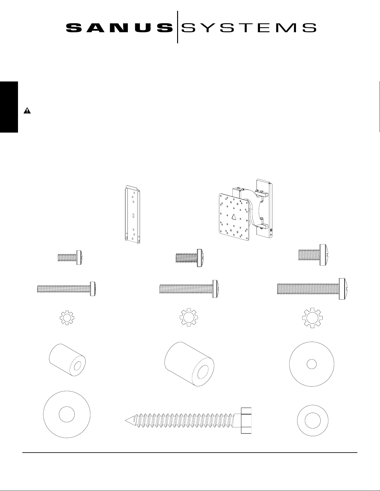
Required Tools: Drill, 3/16” drill bit, wrench set, philips screw driver
Supplied Parts and Hardware: Some parts not shown as actual size*
ENGLISH
(4) M4 x 12 mm Bolt - C
(4) M4 x 30 mm Bolt - F
(4) M4 Lock Washer - I
(4) M4/M5 Spacer - L
(1) Wall Plate - A*
(4) M5 x 12 mm Bolt - D
(4) M5 x 30 mm Bolt - G
(4) M5 Lock Washer - J (4) M6 Lock Washer - K
(1) Arm Assembly - B*
(4) M6 Spacer - M
(4) M6 x 12 mm Bolt - E
(4) M6 x 35 mm Bolt - H
(4) M4/M5 Washer - N
(4) M6 Washer - O
Sanus Systems 2221 Hwy 36 West, Saint Paul, MN 55113 05.10.06 (100044)
Customer Service: 800.359.5520. See complementary Sanus products at www.sanus.com
(3) Lag Bolt - P
(3) Lag Bolt Washer- Q
Page 4

ENGLISH
(3) Wire Tie Clip - R
(2) Safety Bolt - S
(3) Wire Tie - T
Step 1: Mount the Wall Plate: Wood Stud installation only
WARNING: Do not overtighten the Lag Bolts. Overtightening the Lag Bolts may damage or weaken them.
Tighten lag Bolts only until Lag Bolt Washer is pulled rmly against the Wall Plate
Wood Stud Mounting: The Wall Plate (A) must be mounted to a wood stud. Use a high quality stud sensor to locate a stud.
It is a good idea to verify where the stud is located with an awl or thin nail. Pre-drill a 2.5” [63.5 mm] deep hole at the desired
height in the stud using a 3/16” drill bit. Make sure the hole is in the center area of the stud. Use this location for the middle
hole in the Wall Plate. Use the Wall Plate as a template to mark the location of the top and bottom holes. Make sure the Wall
Plate is level and drill a 2.5” [63.5 mm] deep hole using the 3/16” drill bit in the marked locations. Attach the Wall Plate to
the wall using three Lag Bolts (P) and three Lag Bolt Washers (Q). Make sure the Wall Plate is oriented so the at surface
in the center of the plate is against the wall. See Diagram 1 below.
NOTE: The TV will be vertically centered on the Wall Plate once it is mounted.
Diagram 1
A
Q
Stud
(1) Allen Key - U
P
Drywall cutaway
to show studs.
Page 5
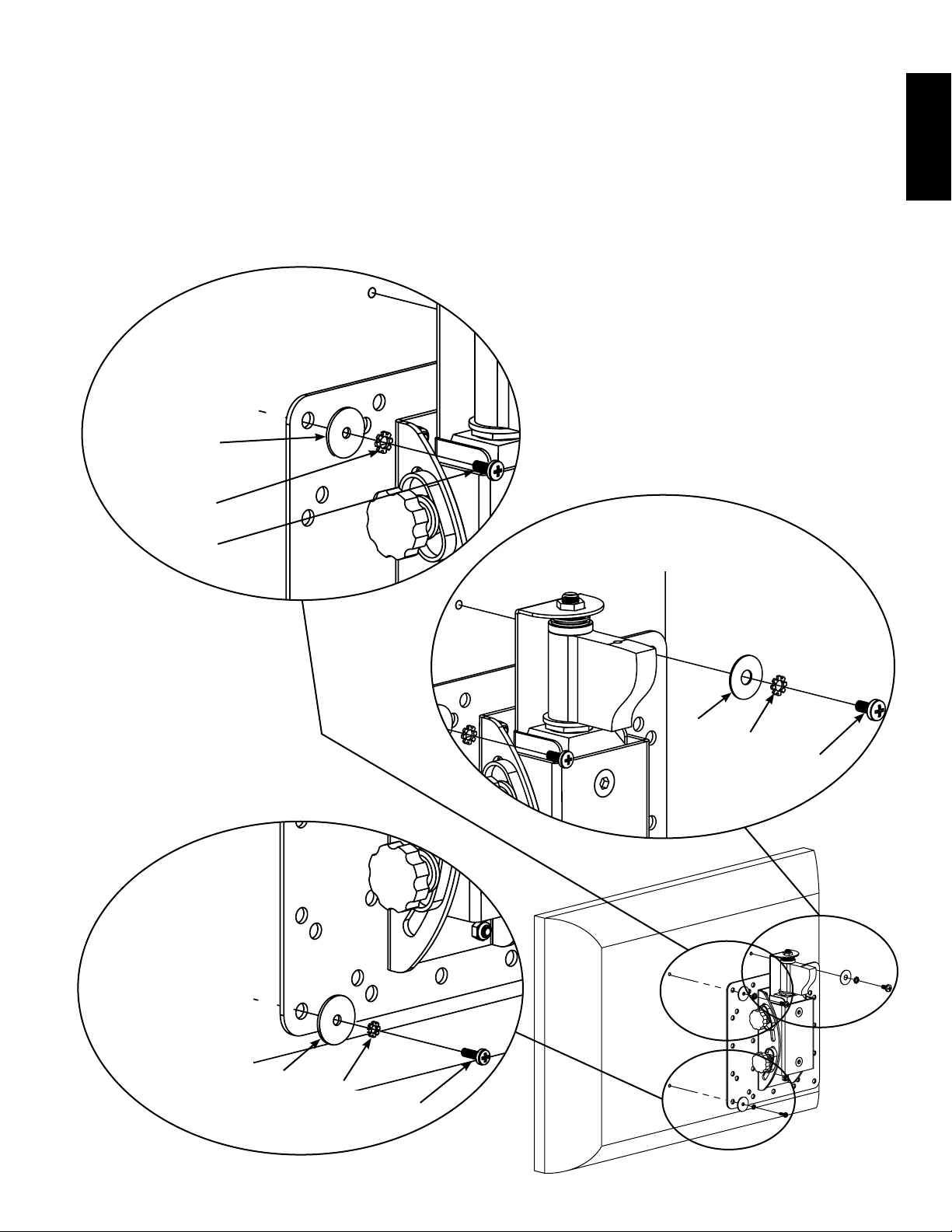
Step 2: Add Arm Assembly to a television with a at back
NOTE: If your television has a curved back, or any other obstruction, proceed directly to Step 3.
First, determine the diameter of the Bolt (C,D,E) your TV requires by hand threading them into the threaded insert on the
back of the TV. If you encounter any resistance stop immediately! Once you have determined the correct diameter, see the
appropriate Diagram below. You will thread the Bolt through the appropriate Lock Washer (I,J,K), a Washer (N, O), the Moni-
tor Plate, and nally thread it into the TV. Proceed to tighten all 4 Bolts until tight with a phillips screw driver.
NOTE: Arm has been cutaway in this Step to show critical parts.
M5 Diameter Bolt
N
M6 Diameter Bolt
J
ENGLISH
D
M4 Diameter Bolt
O
K
E
N
I
C
Page 6

Step 3: Add Arm Assembly to a television with a curved back, recessed area around the threaded inserts or any
other obstruction.
First, determine the diameter of the Bolt (F,G,H) your TV requires by hand threading them into the threaded insert on the
back of the TV. If you encounter any resistance stop immediately! Once you have determined the correct diameter, see
the appropriate Diagram below. You will thread the Bolt through the appropriate Lock Washer (I,J,K), a Washer (N, O), the
Monitor Plate, the appropriate Spacer (L,M) and nally thread it into the TV.
ENGLISH
M5 Diameter Bolt
L
N
J
G
M4 Diameter Bolt
M6 Diameter Bolt
M
O
K
H
L
N
I
F
Page 7
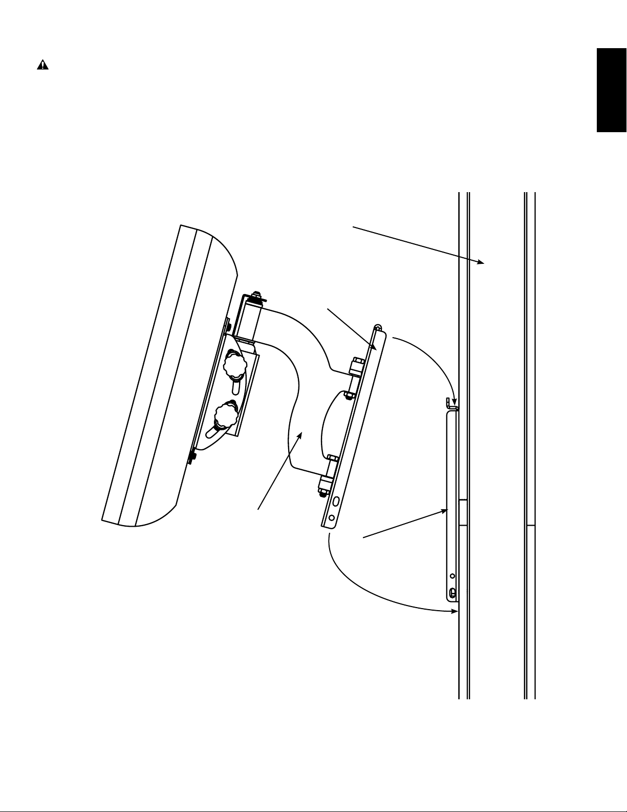
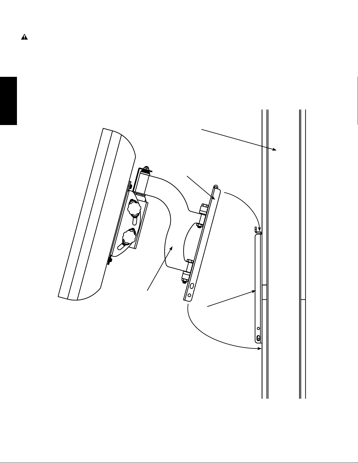
Step 4: Hang Arm Assembly on Wall Plate
WARNING: This step may require 2 people to lift the assembly onto the Wall Plate! Sanus Systems is not responsible for injury or damage.
Orient the Arm Assembly (B) so that the arm extends directly away from the television and the transfer bracket is parallel
with the television. Some televisions will require 2 people to lift! Lift up the assembly and hook the transfer bracket onto
the tab on the top of the Wall Plate (A) as shown in Diagram 4.
Diagram 4
Wall
Transfer Bracket
ENGLISH
B
A
Page 8
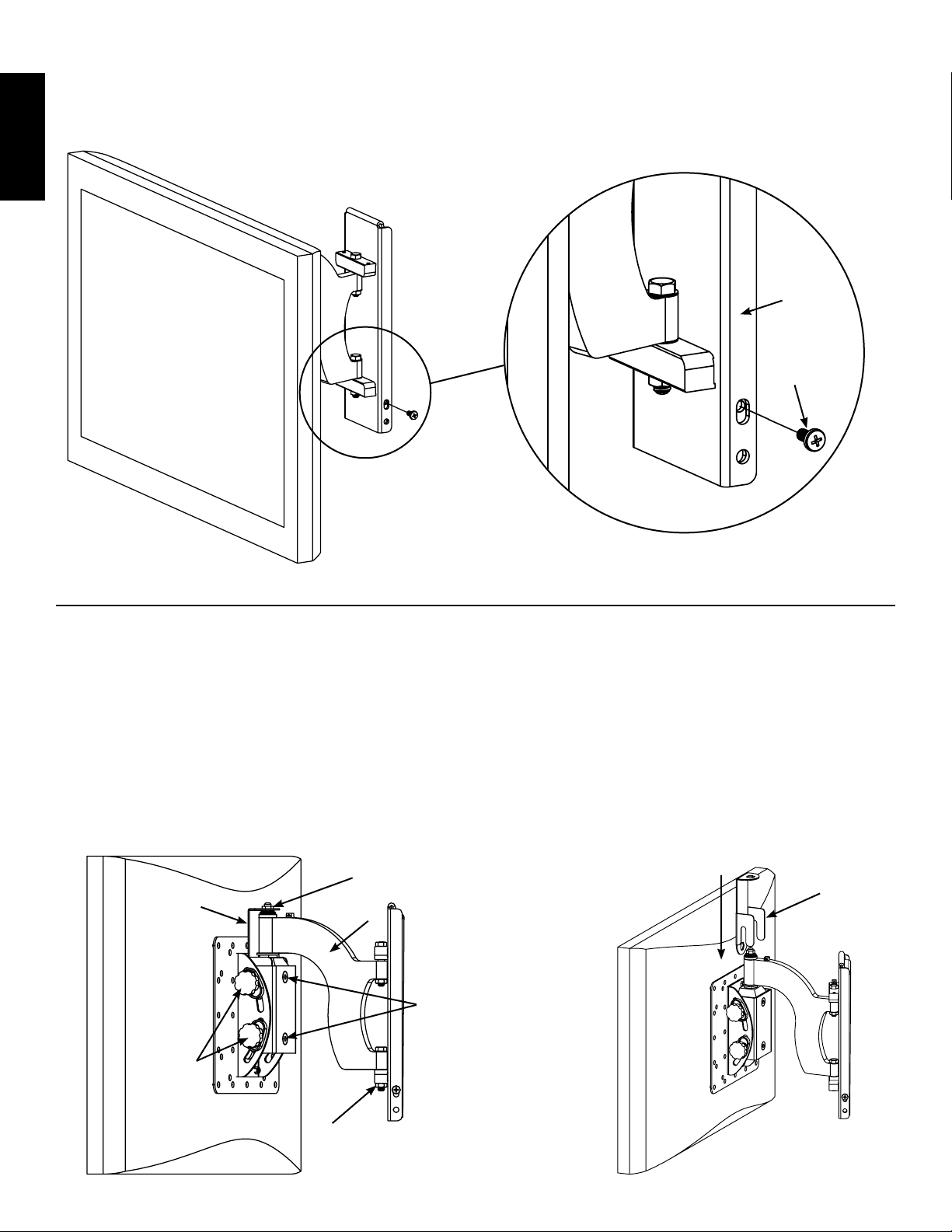
Step 5: Add Safety Bolts
Thread a Safety bolt (S) into the threaded hole on each side of the Transfer Bracket and tighten them with a phillips screwdriver until they are tight. See the detailed View of Diagram 5 for assistance.
ENGLISH
NOTE: Lower Hole on transfer bracket may be used to add a padlock for added security.
Diagram 5
Detailed View
Transfer
Bracket
S
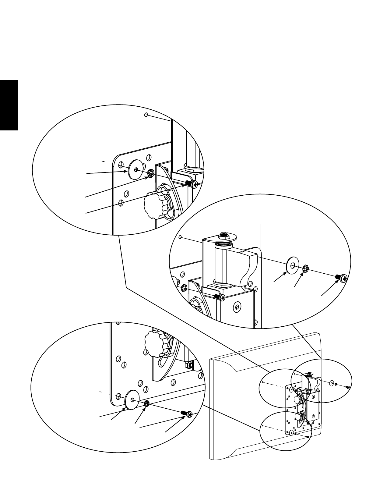
Step 6: Leveling and Adjusting Tension on the Monitor
CAUTION: Do not remove the Tension Nuts labeled in Diagram 6a.
Once the television is mounted onto the Wall Plate (A), and the Safety Bolts (S) are tight, it can be adjusted to level. Slightly
loosen the two Allen Bolts on the back of the Arm Assembly (B). Once those two bolts are loosened, the television can be
adjusted ±6º until level. When the television is level retighten the two Allen Bolts. The tilt can be adjusted by simply tilting
the television. If you need to adjust the tension of the tilt, you can do so with the Tension Knobs. The Tension Nuts labeled
in Diagram 6a can be slightly loosened or tightened to adjust the tension of the Arm Assembly. If you need to adjust the
Tension Nut closest to the TV, you must remove the Safety Bracket, adjust the tension and re-install the Safety Bracket as
shown in the Safety Bracket installation view of Diagram 6b.
Safety
Bracket
Tension
Knobs
Diagram 6a
Tension
Nut
B
Allen
Bolts
Diagram 6b
Safety
Bracket
Tension
Nut
Page 9
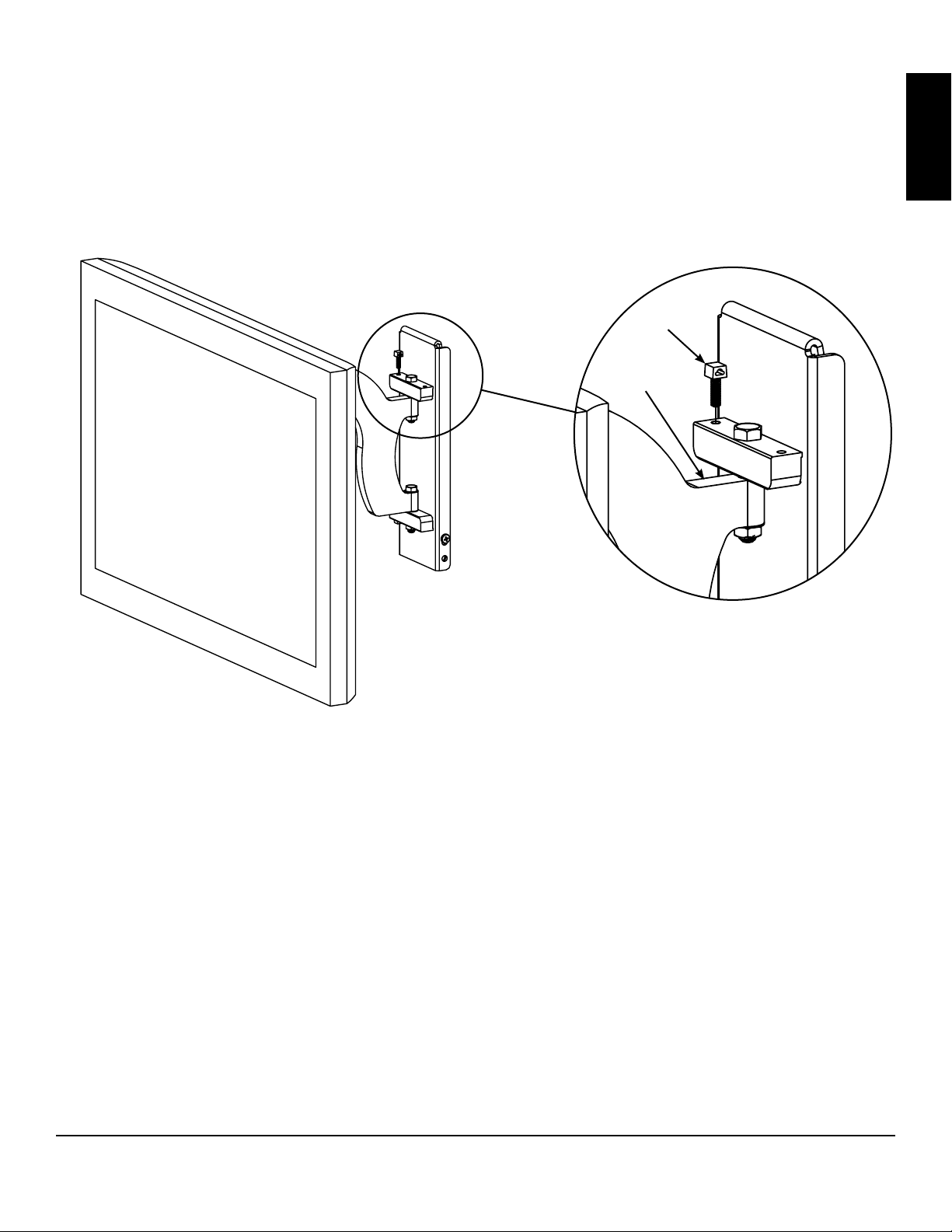
Step 7: Cable/Wire Management
CAUTION: Do not run cables through a pinch point.
Before beginning cable management pull the television into the position as far from the wall as possible. Leave some slack
in the cables so that during motion so there is no added tension on the connectors. Wire Tie Clips (R) can be attached to the
holes in the top and the bottom of the Arm Assembly (B) by simply pressing them into place as shown in the Detailed View
of Diagram 7. Wire Ties (T) can then be added to the Wire Tie Clips.
Diagram 7 Detailed View
R
B
ENGLISH
Sanus Systems 2221 Hwy 36 West, Saint Paul, MN 55113 05.10.06 (100044)
Customer Service: 800.359.5520. See complementary Sanus products at www.sanus.com
Page 10
Instrucciones de ensamblaje del modelo: MF110
L A U N I Ó N D E F O R M A Y F U N C I Ó N
Gracias por elegir un soporte de pared VisionMount™ de Sanus Systems. El modelo MF110 ha sido diseñado para instalar en una pared
vertical pantallas planas LCD con patrón de agujeros VESA (Video Electronics Standards Association) de hasta 200 mm x 200 mm y un
peso de hasta 45,5 kg. Permite extender el televisor una distancia de 24,1 cm desde la pared, girarlo ± 30° (si bien esto podría variar con
el tamaño del aparato), inclinarlo de +5° a -15°, y tener un control de inclinación hacia los lados de ± 6°.
ADVERTENCIA: Si no entiende estas instrucciones o si tiene alguna duda con respecto a la seguridad de la instalación, llame a un
contratista cualicado o comuníquese con Sanus llamando al 800.359.5520 (en EE.UU.) o al 31 (0) 20 5708938 (en Europa). Puede también
visitar nuestro sitio web en www.sanus.com. Revise cuidadosamente los productos para asegurarse de que ninguna pieza falte ni presente
ESPAÑOL
defectos. Nuestros representantes del servicio de atención al cliente le ofrecerán asistencia inmediata con cualquier duda sobre la instalación
o con respecto a piezas faltantes o dañadas. Las piezas de repuesto para los productos comprados a través de un distribuidor autorizado se
enviarán directamente a usted. Nunca use piezas defectuosas. La instalación incorrecta podría ocasionar daños o lesiones graves. No utilice
este producto para nes no explícitamente especicados por Sanus Systems. Sanus Systems no será responsable por daños ni lesiones
debidos al montaje, ensamblaje o uso incorrectos. Llame a Sanus Systems antes de devolver los productos al punto de compra.
Herramientas necesarias: Taladro, broca de 3/16 pulgadas, juego de llaves mecánicas, destornillador Phillips
Piezas y tornillería suministradas: Algunas piezas no se muestran del tamaño real*
(1) Placa de pared - A*
(4) Perno M4 x 12 mm - C
(4) Perno M4 x 30 mm - F
(4) Arandela de seguridad M4 - I
(4) Espaciador M4/M5 - L
(1) Conjunto de brazo - B*
(4) Perno M5 x 12 mm - D
(4) Perno M5 x 30 mm - G
(4) Perno M6 x 12 mm - E
(4) Perno M6 x 35 mm - H
(4) Arandela de seguridad M5 - J (4) Arandela de seguridad M6 - K
(4) Espaciador M6 - M
(4) Arandela M4/M5 - N
(3) Tirafondo - P
(4) Arandela M6 - O
Sanus Systems 2221 Hwy 36 West, Saint Paul, MN 55113 10.05.06 (100044)
Servicio de atención al cliente: 800.359.5520. Vea los productos complementarios de Sanus en el sitio www.sanus.com
(3) Arandela para tirafondo - Q
Page 11

(3) Presilla de banda de amarre - R
(2) Perno de seguridad - S
ESPAÑOL
(3) Banda de amarre - T
Paso 1: Montaje de la placa de pared: Instalación en viga de madera solamente
ADVERTENCIA: No ajuste demasiado los tirafondos, ya que esto podría debilitarlos u ocasionarles daños.
Ajústelos únicamente hasta que la arandela correspondiente quede rmemente apoyada contra la placa de pared.
Instalación sobre viga de madera: La placa de pared (A) deberá montarse sobre una viga de madera. Utilice un detector
de vigas de alta calidad para localizar una viga. Es recomendable vericar la posición de la viga con un punzón o clavo
delgado. Taladre previamente un agujero de 6,4 cm de profundidad a la altura deseada de la viga utilizando una broca de
3/16 pulgadas. Asegúrese de que el agujero quede bien centrado en la viga. Utilice esta posición para el agujero del centro
de la placa de pared y use luego la placa de pared como plantilla para marcar la posición de los agujeros superior e inferior.
Asegúrese de que la placa de pared esté nivelada y utilice una broca de 3/16 pulgadas para perforar agujeros de 6,4 cm
de profundidad en los puntos marcados. Instale la placa para pared utilizando tres tirafondos (P) y tres arandelas para
tirafondo (Q). Asegúrese de que la placa de pared esté orientada de manera que la supercie plana del centro de la placa
quede contra la pared. Vea el diagrama 1 más abajo.
NOTA: El televisor quedará centrado verticalmente en la placa de pared una vez montado.
Diagrama 1
A
Q
Viga
(1) Llave allen - U
P
Vista de pared de
yeso cortada para
mostrar la viga
Page 12
Paso 2: Agregado del conjunto de brazo a un televisor con la parte trasera plana
NOTA: Si su televisor tiene la parte trasera curva o cualquier otra obstrucción, proceda directamente al paso 3.
Determine primero el diámetro de perno (C,D,E) que necesita el televisor. Para ello deberá probar los pernos con la mano en el
inserto roscado que se encuentra en la parte trasera del mismo. Si encuentra alguna resistencia, deténgase inmediatamente.
Una vez que haya determinado el diámetro correcto, vea el diagrama correspondiente más abajo. Haga pasar el perno por
la arandela de seguridad apropiada (I,J,K), una arandela (N,O) y la placa de monitor, y nalmente enrósquelo en el televisor.
Proceda a ajustar rmemente los 4 pernos con un destornillador Phillips.
NOTA: En este paso se ilustra el brazo en forma incompleta para mostrar las partes fundamentales.
Perno de diámetro M5
ESPAÑOL
N
Perno de diámetro M6
J
D
Perno de diámetro M4
O
K
E
N
I
C
Page 13

Paso 3: Agregado del conjunto de brazo a un televisor con la parte trasera curva, una zona hendida alrededor de
los insertos roscados o cualquier otra obstrucción
Determine primero el diámetro de perno (F,G,H) que necesita el televisor. Para ello deberá probar los pernos con la
mano en el inserto roscado que se encuentra en la parte trasera del mismo. Si encuentra alguna resistencia, deténgase
inmediatamente. Una vez que haya determinado el diámetro correcto, vea el diagrama correspondiente más abajo. Haga
pasar el perno por la arandela de seguridad apropiada (I,J,K), una arandela (N,O), la placa de monitor y el espaciador
apropiado (L,M) y nalmente enrósquelo en el televisor.
Perno de diámetro M5
L
N
ESPAÑOL
J
G
Perno de diámetro M4
Perno de diámetro M6
M
O
K
H
L
N
I
F
Page 14
Paso 4: Colgado del brazo en la placa para pared
ADVERTENCIA: En este paso podrían necesitarse 2 personas para levantar el conjunto hasta la placa de pared.
Sanus Systems no será responsable por lesiones o daños.
Oriente el conjunto de brazo (B) de manera que se extienda directamente desde el televisor y el soporte de transferencia
quede paralelo a este último. Se requerirán dos personas para levantar algunos televisores. Levante el conjunto y
enganche el soporte de transferencia en la pestaña situada en la parte superior de la placa de pared (A) como se ilustra
en el diagrama 4.
Diagrama 4
ESPAÑOL
Pared
Soporte de transferencia
B
A
Page 15

Paso 5: Agregado de los pernos de seguridad
Enrosque un perno de seguridad (S) en cada uno de los agujeros roscados situados en los lados del soporte de transferencia
y ajústelo con un destornillador Phillips hasta que quede apretado. Consulte la vista detallada del diagrama 5 como ayuda.
Diagrama 5
NOTA: Puede utilizarse el agujero inferior del soporte de transferencia para agregar un candado y obtener
mayor seguridad.
Vista detallada
Soporte de
transferencia
S
ESPAÑOL
Paso 6: Nivelación del monitor y ajuste de la tensión
PRECAUCIÓN: No retire las tuercas reguladoras de la tensión que se muestran en el diagrama 6a.
Una vez que el televisor esté montado en la placa para pared (A) y los pernos de seguridad (S) estén apretados, se podrá
ajustar el nivel. Aoje ligeramente los dos pernos allen de la parte trasera del conjunto de brazo (B). Una vez que ambos
pernos estén ojos, ajuste el televisor ± 6º hasta que quede nivelado. Después de nivelar el televisor, vuelva a ajustar los
dos pernos allen. La inclinación puede ajustarse simplemente inclinando el televisor. Para ajustar la tensión de la inclinación
deberán utilizarse las perillas correspondientes. Las tuercas reguladoras de la tensión que se muestran en el diagrama
6a pueden aojarse o ajustarse levemente para ajustar la tensión del brazo. Si necesita ajustar la tuerca reguladora de la
tensión más cercana al televisor, deberá retirar el soporte de seguridad, ajustar la tensión y nalmente volver a instalar el
soporte de seguridad, tal como se muestra en la vista correspondiente del diagrama 6b.
Soporte de
seguridad
Perillas
de tensión
Diagrama 6a
Tuerca reguladora
de la tensión
B
Pernos
allen
Diagrama 6b
Soporte de
seguridad
Tuerca reguladora
de la tensión
Page 16

Paso 7: Manejo de los cables
PRECAUCIÓN: Los cables no deberán pasar por lugares donde puedan quedar pinzados.
Antes de iniciar la instalación de los cables, mueva el televisor a la posición que esté lo más lejos posible de la pared. Los
cables deberán estar sucientemente ojos para que durante el movimiento no se tensen más los conectores. Las presillas
de las bandas de amarre (R) pueden colocarse en los agujeros de las partes superior e inferior del conjunto de brazo (B)
simplemente presionándolas para que encajen en su lugar como se ilustra en la vista detallada del diagrama 7. Luego
pueden agregarse las bandas de amarre (T) a las presillas.
Diagrama 7 Vista detallada
ESPAÑOL
R
B
Sanus Systems 2221 Hwy 36 West, Saint Paul, MN 55113 10.05.06 (100044)
Servicio de atención al cliente: 800.359.5520. Vea los productos complementarios de Sanus en el sitio www.sanus.com
Page 17

Montageanleitung für Modell: MF110
D I E E I N H E I T V O N F O R M U N D F U N K T I O N
Wir freuen uns, dass Sie sich für eine VisionMount™-Wandhalterung von Sanus Systems entschieden haben. Modell VM110 ist für die
Montage von LCD-Flachbildfernsehgeräten mit einem VESA-Schraubanschluss von bis zu 20 cm x 20 cm und einem Maximalgewicht
von 45,5 kg an einer vertikalen Wand vorgesehen. Das Fernsehgerät kann bis zu 24,1 cm von der Wand weggezogen werden. Es kann
um ± 30° geschwenkt (je nach Größe des Geräts), um +5° bis -15° geneigt und um ± 6° gedreht werden.
VORSICHT: Wenn Sie diese Anweisungen nicht verstehen oder Zweifel an der Sicherheit der Montage haben, rufen Sie einen Fachmann
an oder wenden Sie sich telefonisch an Sanus Systems unter +1-800-359-5520 (USA) oder +31-(0)20-570-8938 (Europa). Sie können auch
unsere Website besuchen: www.sanus.com. Prüfen Sie sorgfältig, ob Teile fehlen oder defekt sind. Unsere Kundendienstmitarbeiter können
Ihnen bei Fragen zur Montage und bei fehlenden oder beschädigten Teilen schnell weiterhelfen. Ersatzteile für bei autorisierten Fachhändlern
gekaufte Sanus-Produkte werden direkt an Ihre Adresse versendet. Verwenden Sie niemals beschädigte Teile! Unsachgemäße Montage
kann Schäden am Gerät und schwere Verletzungen hervorrufen. Verwenden Sie das Produkt nicht für andere als von Sanus Systems
explizit genannte Zwecke. Sanus Systems haftet nicht für Schäden oder Verletzungen, die durch unsachgemäße Montage, fehlerhaften
Zusammenbau oder unsachgemäße Nutzung entstehen. Bitte rufen Sie Sanus Systems an, bevor Sie Produkte beim Händler reklamieren.
Erforderliche Werkzeuge: Bohrmaschine, 3/16-Zoll-Bohrer, Schlüsselsatz, Phillips-Kreuzschlitzschraubendreher
Mitgelieferte Teile und Zubehör: Einige Teile sind nicht in Originalgröße abgebildet*
DEUTSCH
(1) Wandplatte – A*
(4) Schraube M4 x 12 mm – C
(4) Schraube M4 x 30 mm – F
(4) Sicherungsscheibe M4 – I
(4) Abstandhalter M4/M5 – L
(1) Schwenkarm – B*
(4) Schraube M5 x 12 mm – D
(4) Schraube M5 x 30 mm – G
(4) Schraube M6 x 12 mm – E
(4) Schraube M6 x 35 mm – H
(4) Sicherungsscheibe M5 – J (4) Sicherungsscheibe M6 – K
(4) Abstandhalter M6 – M
(4) Unterlegscheibe M4/M5 – N
(3) Holzschraube – P
(4) Unterlegscheibe M6 – O
Sanus Systems 2221 Hwy 36 West, Saint Paul, MN 55113, USA 05.10.06 (100044)
Kundendienst: 800.359.5520. Ergänzende Sanus-Produkte nden Sie unter www.sanus.com.
(3) Holzschraubenunterleg
scheibe – Q
Page 18

(3) Kabelbinderführung – R
(2) Sicherungsschraube – S
(3) Kabelbinder – T
Schritt 1: Wandplatte montieren: Nur für Montage an Holzträgerbalken
DEUTSCH
VORSICHT: Die Holzschrauben nicht überdrehen. Durch Überdrehen werden die Holzschrauben beschädigt oder
geschwächt. Die Holzschrauben nur soweit festziehen, bis die Unterlegscheibe fest gegen die Wandplatte drückt.
Montage an einem Holzbalkenträger: Die Wandplatte (A) muss an einem Trägerbalken montiert werden. Suchen Sie
den Träger mit einem hochwertigen Sensor. Es ist sinnvoll, die Lage des Trägers mit einer Ahle oder einem dünnen Nagel
zu überprüfen. An der entsprechenden Position in jedem Trägerbalken mit einem 3/16-Zoll-Bohrer ein Loch mit einer Tiefe
von 6,4 cm vorbohren. Die Bohrung muss sich im Mittelbereich des Trägerbalkens benden. Diesen Punkt für die mittlere
Bohrung in der Wandplatte verwenden. Die Wandplatte als Schablone zur Markierung der oberen und unteren Bohrungen
verwenden. Die Wandplatte ausrichten und an der Markierung mit einem 3/16-Zoll-Bohrer ein 6,4 cm tiefes Loch bohren. Die
Wandplatte mit drei Holzschrauben (P) und drei Holzschraubenunterlegscheiben Q an der Wand montieren). Die Wandplatte
muss so ausgerichtet sein, dass die ache Oberäche in der Mitte der Platte zur Wand zeigt. Siehe Abbildung 1.
HINWEIS: Das Fernsehgerät wird beim Montieren vertikal auf der Wandplatte zentriert.
Abbildung 1
A
Q
Trägerbalken
(1) Inbusschlüssel – U
P
Schnittbild der
Trockenwand
zur Darstellung der
Trägerbalken.
Page 19

Schritt 2: Montage des Schwenkarms an einem Fernsehgerät mit acher Rückseite
HINWEIS: Für die Montage eines Fernsehgeräts mit gewölbter Rückseite oder anderen Hindernissen siehe Schritt 3.
Zunächst durch probeweises Eindrehen der Schrauben in die Gewindeeinsätze an der Rückseite des Fernsehgeräts
die erforderliche Schraubengröße (C,D,E) für das Fernsehgerät bestimmen. Wenn ein Widerstand zu spüren ist, sofort
aufhören! Sobald der korrekte Durchmesser ermittelt ist, die entsprechende Abbildung unten beachten. Die Schraube
durch die entsprechende Sicherungsscheibe (I,J,K), die dazugehörige Unterlegscheibe (N, O) und die Monitorplatte in das
Fernsehgerät drehen. Alle vier Schrauben mit einem Phillips-Kreuzschlitzschraubendreher festziehen.
HINWEIS: Schnittbild des Schwenkarms dient zur Darstellung wichtiger Teile in diesem Schritt.
Schraube M5
N
Schraube M6
J
DEUTSCH
D
Schraube M4
O
K
E
N
I
C
Page 20

Schritt 3: Montage des Schwenkarms an einem Fernsehgerät mit gewölbter Rückseite, Aussparungen um die
Gewindeeinsätze oder anderen Hindernissen
Zunächst die erforderliche Schraubengröße (F,G,H) für das Fernsehgerät durch probeweises Eindrehen der Schrauben in
die Gewindeeinsätze an der Rückseite des Fernsehgeräts bestimmen. Wenn ein Widerstand zu spüren ist, sofort aufhören!
Sobald der korrekte Durchmesser ermittelt ist, die entsprechende Abbildung unten beachten. Die Schraube durch die
entsprechende Sicherungsscheibe (I, J, K), die dazugehörige Unterlegscheibe (N, O) die Monitorplatte, den geeigneten
Abstandhalter (L, M) und schließlich in das Fernsehgerät drehen.
Schraube M5
L
N
DEUTSCH
J
Schraube M6
G
Schraube M4
M
O
K
H
L
N
I
F
Page 21

Schritt 4: Schwenkarm an der Wandplatte aufhängen
VORSICHT: Möglicherweise sind zwei Personen erforderlich, um die komplette Baugruppe auf die Wandplatte
zu heben! Sanus Systems haftet nicht für Personen- oder Sachschäden.
Den Schwenkarm (B) so drehen, dass er direkt vom Fernsehgerät weg zeigt und die Transferhalterung parallel zum Fernsehgerät
steht. Bei manchen Fernsehgeräten sind zwei Personen zum Anheben erforderlich! Die komplette Baugruppe anheben und
die Transferhalterung auf der Nase an der Oberseite der Wandplatte (A) einhaken, siehe Abbildung 4.
Abbildung 4
Wand
Transferhalterung
B
DEUTSCH
A
Page 22

Schritt 5: Montage der Sicherungsschrauben
Eine Sicherungsschraube (S) in die Gewindebohrung an beiden Seiten der Transferhalterung eindrehen und mit einem Phil-
lips-Kreuzschlitzschraubendreher festziehen. Siehe dazu Detailansicht in Abbildung 5.
Abbildung 5
Detailansicht
Transfer-
halterung
S
DEUTSCH
HINWEIS: In die untere Bohrung der Transferhalterung kann zur zusätzlichen Sicherheit ein Vorhängeschloss
eingehängt werden.
Schritt 6: Monitor ausrichten und Befestigung einstellen
VORSICHT: Die Sicherungsmuttern in Abbildung 6a dürfen nicht herausgedreht werden.
Wenn das Fernsehgerät an der Wandplatte (A) montiert ist und die Sicherungsschrauben (S festgezogen sind, kann das
Fernsehgerät horizontal ausgerichtet werden. Die beiden Inbusschrauben an der Rückseite der Schwenkvorrichtung (B)
leicht lockern. Sobald die beiden Schrauben gelockert sind, lässt sich das Fernsehgerät um ±6º verstellen, bis er horizontal
ausgerichtet ist. Wenn das Fernsehgerät horizontal ausgerichtet ist, die beiden Inbusschrauben wieder festziehen. Die
Neigung lässt sich durch Neigen des Fernsehgeräts einstellen. Die Leichtgängigkeit der Neigung wird mit den Siche
rungsrändelschrauben reguliert. Die in Abbildung 6a gekennzeichneten Sicherungsmuttern können zur Einstellung der
Leichtgängigkeit des Schwenkarms leicht gelockert oder angezogen werden. Zur Verstellung der Sicherungsmutter direkt
am Fernsehgerät muss zur Einstellung der Leichtgängigkeit die Sicherheitshalterung demontiert und anschließend wieder
montiert werden (siehe Ansicht zur Montage der Sicherungshalterung in Abbildung 6b).
Sicherungs-
halterung
Abbildung 6a
Sicherungs-
mutter
B
Inbus-
schrauben
Abbildung 6b
Sicherungs-
halterung
Sicherungs-
rändel-
schrauben
Sicherungs-
mutter
Page 23

Schritt 7: Kabelführung
VORSICHT: Kabel nicht durch Stellen führen, an denen Quetschgefahr besteht!
Vor dem Verlegen der Kabel das Fernsehgerät so weit wie möglich von der Wand wegziehen. Die Kabel locker verlegen,
so dass bei Bewegungen keine Zugbelastung der Steckverbinder eintritt. In die Bohrungen an der Ober- und Unterseite
des Schwenkarms (B) lassen sich Kabelbinderführungen (R) einbauen, die wie in der Detailansicht von Abbildung 7 gezeigt
eingedrückt werden. Anschließend können die Kabelbinder (T) an den Kabelbinderführungen befestigt werden.
Abbildung 7 Detailansicht
R
B
DEUTSCH
Sanus Systems 2221 Hwy 36 West, Saint Paul, MN 55113, USA 05.10.06 (100044)
Kundendienst: 800.359.5520. Ergänzende Sanus-Produkte nden Sie unter www.sanus.com.
Page 24

Instructions de montage pour le modèle : MF110
L’ U N I O N D E L A F O R M E E T D E L A F O N C T I O N
Nous vous remercions d’avoir choisi un montant mural VisionMount™ de Sanus Systems. Le MF110 est conçu pour xer sur un mur vertical
des téléviseurs LCD à écran plat possédant une conguration de trous de montage VESA (Video Electronics Standards Association) dont les
mesures peuvent atteindre 20 cm x 20 cm et le poids 45,5 kg. Il permet d’éloigner le téléviseur de 24,1 cm du mur. Il permet aussi de faire
pivoter le téléviseur de ± 30° (peut varier selon la taille du téléviseur), de l’incliner de + 5° à - 15° et même de le faire tourner de ± 6°.
AVERTISSEMENT : si vous ne comprenez pas ces instructions ou si vous avez un doute quant à la sécurité de cette installation, veuillez
faire appel à un technicien qualié ou communiquez avec Sanus en composant le 1-800-359-5520 (aux É.-U.), ou le 31 (0) 20 5708938
(pour l’Europe). Vous pouvez également visiter notre site web au www.sanus.com. Vériez soigneusement qu’il n’y a aucune pièce
manquante ou défectueuse. Les représentants de notre service à la clientèle peuvent répondre rapidement à toute question concernant
l’installation ou des pièces manquantes ou endommagées. Les pièces de rechange de produits achetés auprès de distributeurs agréés
vous seront livrées directement. N’utilisez jamais de pièces défectueuses. Une installation incorrecte peut entraîner des dommages ou
des blessures graves. Ce produit ne doit être utilisé que pour des usages explicitement spéciés par Sanus Systems. Sanus Systems ne
pourra être tenu responsable de dommages ou de blessures dus à un montage incorrect, un assemblage incorrect ou un usage incorrect.
Veuillez contacter Sanus Systems avant de renvoyer des produits au point de vente.
Outils nécessaires : perceuse, mèche de 3/16 pouce, jeu de clés, tournevis cruciforme
Pièces et matériel fournis : certaines pièces ne sont pas illustrées grandeur réelle*
FRANÇAIS
(1) Plaque murale - A*
(4) Vis M4 x 12 mm - C
(4) Vis M4 x 30 mm - F
(4) Rondelle de blocage M4 - I
(4) Entretoise M4/M5 - L
(1) Bras - B*
(4) Vis M5 x 12 mm - D
(4) Vis M5 x 30 mm - G
(4) Vis M6 x 12 mm - E
(4) Vis M6 x 35 mm - H
(4) Rondelle de blocage M5 - J (4) Rondelle de blocage M6 - K
(4) Entretoise M6 - M
(4) Rondelle M4/M5 - N
(4) Rondelle M6 - O
(3) Tire-fond - P
Sanus Systems 2221 Hwy 36 West, Saint Paul, MN 55113, États-Unis 10.05.06 (100044)
Service à la clientèle : 800.359.5520. Pour les produits Sanus complémentaires, visitez le site www.sanus.com
(3) Rondelle de tire-fond - Q
Page 25

(3) Attache de serre-câble - R
(2) Vis de sécurité - S
(3) Serre-câble - T
Étape 1 : Montage de la plaque murale : installation sur ossature de bois seulement
AVERTISSEMENT : ne serrez pas excessivement les tire-fond. Un serrage excessif risque d’endommager ou d’affaiblir
les tire-fond. Ne serrez les tire-fond que jusqu’à ce que la rondelle soit tirée fermement contre la plaque murale.
Montage sur ossature de bois : la plaque murale (A) doit être montée sur une ossature en bois. Servez-vous d’un
détecteur de montants de haute qualité pour repérer un montant. Il est préférable de vérier l’emplacement des montants
à l’aide d’un poinçon ou d’un clou mince. Percez un avant-trou de 6,4 cm de profondeur à la hauteur souhaitée dans le
montant à l’aide d’une mèche de 3/16 pouce. Assurez-vous que le trou se trouve bien dans la zone centrale du montant. Ce
trou servira d’emplacement pour le trou central de la plaque murale. Utilisez la plaque murale comme gabarit pour marquer
l’emplacement des trous supérieur et inférieur. Assurez-vous que la plaque murale est de niveau et percez un trou de
6,4 cm de profondeur à l’aide d’une mèche de 3/16 pouce aux emplacements marqués. Fixez la plaque murale sur le mur à
l’aide des trois tire-fond (P) et des trois rondelles de tire-fond (Q). Assurez-vous que la plaque murale est orientée de façon
à ce que la surface plate au centre de la plaque soit contre le mur. Reportez-vous au schéma 1 ci-dessous.
REMARQUE : le téléviseur sera centré verticalement sur la plaque murale une fois installé.
Schéma 1
(1) Clé Allen - U
FRANÇAIS
A
Q
P
Montant
Vue en coupe
d’une cloison
en placoplâtre
pour indiquer
les montants.
Page 26

Étape 2 : Montage du bras sur un téléviseur à panneau arrière plat
REMARQUE : si votre téléviseur comporte un panneau arrière courbé ou présente une obstruction à l’arrière,
passez directement à l’étape 3.
Déterminez d’abord le diamètre de la vis (C, D, E) compatible avec votre téléviseur en les vissant à la main dans l’insert leté
à l’arrière de l’appareil. Si vous ressentez une résistance quelconque, arrêtez immédiatement ! Une fois le bon diamètre
déterminé, reportez-vous au schéma correspondant ci-dessous. Vissez la vis dans la rondelle de blocage appropriée
(I, J, K), une rondelle (N, O), la plaque du moniteur et nalement le téléviseur. Serrez les quatre vis de manière à ce qu’elles
soient bien ajustées à l’aide d’un tournevis cruciforme.
REMARQUE : la vue en coupe du bras à cette étape permet de montrer les pièces essentielles.
Vis de diamètre M5
N
FRANÇAIS
Vis de diamètre M6
J
D
O
K
E
Vis de diamètre M4
N
I
C
Page 27

Étape 3 : Montage du bras sur un téléviseur à panneau arrière courbé, avec renfoncement autour des inserts letés
ou présentant un autre type d’obstruction.
Déterminez d’abord le diamètre de la vis (F, G, H) compatible avec votre téléviseur en les vissant à la main dans l’insert leté
à l’arrière de l’appareil. Si vous ressentez une résistance quelconque, arrêtez immédiatement ! Une fois le bon diamètre
déterminé, reportez-vous au schéma correspondant ci-dessous. Vissez la vis dans la rondelle de blocage appropriée
(I, J, K), une rondelle (N, O), la plaque du moniteur, l’entretoise correspondante (L, M) et nalement le téléviseur.
Vis de diamètre M5
L
N
J
G
Vis de diamètre M4
Vis de diamètre M6
FRANÇAIS
M
O
K
H
L
N
I
F
Page 28

Étape 4 : Montage du bras sur la plaque murale
AVERTISSEMENT : cette étape nécessite l’intervention de deux personnes pour soulever l’assemblage et
l’accrocher sur la plaque murale ! Sanus Systems n’assume aucune responsabilité en cas de blessures ou de
dommages.
Orientez le bras (B) de sorte qu’il se déploie directement par rapport au téléviseur et que le support de transfert soit parallèle
au téléviseur. Dans certains cas, l’intervention de 2 personnes est nécessaire pour soulever le téléviseur !
l’assemblage et accrochez le support de transfert sur la patte en haut de la plaque murale (A), comme indiqué sur le
schéma 4.
Schéma 4
Mur
Support de transfert
Soulevez
FRANÇAIS
B
A
Page 29

Étape 5 : Pose des vis de sécurité
Enlez une vis de sécurité (S) dans les trous letés de chaque côté du support de transfert et serrez-les à l’aide d’un
tournevis cruciforme jusqu’à ce qu’elles soient bien serrées. Reportez-vous à la vue détaillée du schéma 5 si vous avez
besoin d’aide.
Schéma 5
REMARQUE : le trou inférieur du support de transfert peut être utilisé pour placer un cadenas pour plus de sécurité.
Vue détaillée
Support
de transfert
S
FRANÇAIS
Étape 6 : Mise à niveau et réglage de la tension du moniteur
ATTENTION : ne retirez pas les écrous de tension indiqués sur le schéma 6a.
Une fois le téléviseur installé sur la plaque murale (A) et les vis de sécurité (S) bien serrées, vous pouvez régler le niveau.
Il suft de desserrer légèrement les deux vis Allen situées à l’arrière du bras (B). Après avoir desserré ces deux vis, vous
pouvez régler la position du téléviseur de ± 6º jusqu’à ce que l’appareil soit de niveau. Une fois le téléviseur de niveau,
resserrez les deux vis Allen. Vous pouvez régler l’inclinaison du téléviseur d’un simple mouvement de la main. Si vous devez
régler la tension de l’inclinaison, vous pouvez le faire à l’aide des boutons de réglage de tension. Il est possible de serrer
ou de desserrer légèrement les écrous de tension illustrés sur le schéma 6a pour régler la tension du bras. Si vous voulez
régler l’écrou de tension le plus rapproché du téléviseur, vous devez enlever le support de sécurité, rajuster la tension et
réinstaller le support de sécurité, comme indiqué dans la vue de l’installation du support de sécurité sur le schéma 6b.
Support
de sécurité
Boutons
de réglage
de tension
Schéma 6a
Écrou
de tension
B
Vis
Allen
Schéma 6b
Support
de sécurité
Écrou
de tension
Page 30

Étape 7 : Aménagement des câbles/ls
ATTENTION : évitez les points de pincement lors de l’acheminement des câbles.
Avant de procéder à l’aménagement des câbles, mettez le téléviseur dans la position la plus éloignée du mur que possible.
Les câbles doivent être sufsamment lâches pour ne pas créer une tension supplémentaire sur les connecteurs pendant le
déplacement. Les attaches de serre-câble (R) peuvent être xées dans les trous sur les parties supérieure et inférieure du
bras (B) par simple pression pour la mise en place, comme indiqué sur la vue détaillée du schéma 7. Des serre-câble (T)
peuvent ensuite être ajoutés aux attaches de serre-câble.
Schéma 7 Vue détaillée
R
B
FRANÇAIS
Sanus Systems 2221 Hwy 36 West, Saint Paul, MN 55113, États-Unis 10.05.06 (100044)
Service à la clientèle : 800.359.5520. Pour les produits Sanus complémentaires, visitez le site www.sanus.com
Page 31

Istruzioni di montaggio per il modello MF110
L ' U N I O N E D I F O R M A E F U N Z I O N E
Grazie per aver scelto un sistema di montaggio per parete Sanus Systems VisionMount™. Il MF110 è progettato per montare su una
parete verticale televisori a pannello piatto LCD no a 20 x 20 cm e che raggiungono un peso di 45,5 kg con maschera di foratura Vesa
che consente di creare una distanza dalla parete di 24,1 cm. In tal modo è possibile inclinare il televisore di ±30° (può variare con le
dimensioni del televisore), orientare di +5° no a -15° e avere il controllo del rollio di ±6°.
AVVERTENZA: se queste istruzioni risultano poco chiare o si hanno dubbi sulla sicurezza dell’installazione, rivolgersi a un installatore
specializzato o contattare la Sanus al numero verde USA 800.359.5520 o, in Europa, al numero +31 (0) 20 5708938. È anche possibile
visitare il sito www.sanus.com. Controllare attentamente che non vi siano parti mancanti o difettose. Il nostro servizio di assistenza clienti
potrà rispondere rapidamente alle domande relative all’installazione o alle parti mancanti o danneggiate. Le parti di ricambio per i prodotti
acquistati attraverso i rivenditori autorizzati vengono spedite direttamente al cliente. Non utilizzare parti difettose. L’installazione errata
può causare danni o lesioni gravi. Non utilizzare questo prodotto per scopi diversi da quelli specicamente indicati dalla Sanus Systems.
La Sanus Systems non è responsabile di danni o lesioni causati da montaggio o utilizzo non corretti. Chiamare la Sanus Systems prima
di riportare i prodotti al punto vendita.
Strumenti necessari: trapano con punta da 3/16 di pollice, un set di chiavi e un cacciavite Phillips
Parti e minuteria metallica fornite: alcune parti in gura non sono nelle dimensioni reali*
(1) Piastra a parete - A*
(1) Gruppo del braccio - B*
ITALIANO
(4) Bullone M4 x 1,2 cm - C
(4) Bullone M4 x 3 cm - F
(4) Controrondella M4 - I
(4) Bullone M5 x 1,2 cm - D
(4) Bullone M5 x 3 cm - G
(4) Controrondella M5 - J (4) Controrondella M6 - K
(4) Bullone M6 x 1,2 cm - E
(4) Bullone M6 x 3,5 cm - H
(4) Distanziale M4/M5 - L
(4) Distanziale M6 - M
(4) Rondella M4/M5 - N
(3) Tirafondi - P
(4) Rondella M6 - O
Sanus Systems 2221 Hwy 36 West, Saint Paul, MN 55113 05.10.06 (100044)
Assistenza clienti (numero verde USA): 800.359.5520. Vedere i prodotti complementari Sanus sul sito www.sanus.com
(3) Rondella per tirafondo - Q
Page 32

(3) Clip tirali - R
(2) Bullone di sicurezza - S
(3) Tirali - T
Fase 1: Montaggio della piastra a parete: solo installazione su assi di legno
AVVERTENZA: non serrare eccessivamente i tirafondi, altrimenti potrebbero danneggiarsi o allentarsi.
Serrare i tirafondi solo no a quando la rondella del tirafondi non poggia saldamente contro la piastra per parete.
Montaggio su assi di legno: la piastra a parete (A) va montata su un asse di legno. Usare un rilevatore di travi di legno di
alta qualità per individuare le travi di legno nella parete. È consigliabile vericare la posizione degli assi con un punteruolo o
con un chiodo sottile. Eseguire un foro preliminare a una profondità di 6,4 cm all’altezza desiderata della trave, usando una
punta per trapano da 3/16 di pollice. Assicurarsi che il foro si trovi nell’area centrale della trave. Utilizzare questa posizione
per il foro centrale della piastra a per parete. Utilizzare la piastra a parete come maschera per contrassegnare la posizione
dei fori superiori e inferiori. Assicurarsi che la piastra a parete sia a livello ed eseguire un foro nelle posizioni contrassegnate
alla profondità di 6,4 cm usando una punta per trapano da 3/16 di pollice. Collegare la piastra alla parete usando i tre
tirafondi (P) e le tre rondelle per tirafondo (Q). Assicurarsi che la piastra per parete sia orientata in modo che la supercie
piatta al centro della piastra si trovi contro la parete. Vedere la gura 1 di seguito.
NOTA: una volta montato il televisore deve essere centrato verticalmente sulla piastra per parete.
ITALIANO
Figura 1
(1) Chiave a brugola - U
A
Q
P
Asse
Spaccato del
cartongesso per
mostrare gli assi
Page 33

Fase 2: Aggiunta del gruppo del braccio a un televisore con retro piatto
NOTA: se il televisore ha il retro curvo o altro tipo di ostruzione, passare direttamente alla Fase 3.
Innanzitutto, stabilire il diametro dei bulloni (C,D,E) adatto al televisore, avvitandoli a mano nell’inserto lettato sul retro
della TV. Se si incontrano delle resistenze, bloccarsi immediatamente Una volta determinato il diametro corretto, vedere la
gura appropriata che segue. Il bullone va avvitato con la controrondella appropriata (I,J,K), una rondella (N, O), la staffa
del monitor e poi inne al televisore. Procedere serrando i 4 bulloni con un cacciavite Phillips.
NOTA: spaccato del braccio in questa fase per mostrare le fasi critiche.
Bullone di diametro M5
N
Bullone di diametro M6
J
D
Bullone di diametro M4
ITALIANO
O
K
E
N
I
C
Page 34

Fase 3: Aggiunta del gruppo del braccio a un televisore con retro curvo, inserti lettati con recesso o altro tipo
di ostruzione.
Innanzitutto, stabilire il diametro dei bulloni (F,G,H) adatto al telvisore, avvitandoli a mano nell’inserto lettato sul retro della
TV. Se si incontrano delle resistenze, bloccarsi immediatamente Una volta determinato il diametro corretto, vedere la gura
appropriata che segue. Il bullone va avvitato con la controrondella appropriata (I,J,K), una rondella (N, O), la staffa del
monitor, il distanziale corretto (L,M) e inne al televisore.
Bullone di diametro M5
L
N
ITALIANO
J
G
Bullone di diametro M4
Bullone di diametro M6
M
O
K
H
L
N
I
F
Page 35

Fase 4: Inserimento del gruppo del braccio sulla piastra a parete
AVVERTENZA: questa fase può richiedere la presenza di 2 persone per sollevare il gruppo sulla piastra a parete
La Sanus Systems non è responsabile di eventuali lesioni o danni.
Orientare il gruppo del braccio (B) in modo che il braccio si estenda lontano dal televisore e che la staffa di trasferimento
sia parallela al televisore. Per sollevare alcuni televisori possono essere necessarie 2 persone. Sollevare il gruppo
e agganciare la staffa di trasferimento sulla linguetta nella parte superiore della piastra a parete (A), come mostrato nella
Figura 4.
Figura 4
Parete
Staffa di trasferimento
ITALIANO
B
A
Page 36

Fase 5: Aggiunta dei bulloni di sicurezza
Avvitare un bullone di sicurezza (S) nel foro lettato su ciascun lato della staffa di trasferimento e serrare con un cacciavite
Phillips. Vedere la vista dettagliata della gura 5 per assistenza.
Figura 5
NOTA: il foro inferiore sulla staffa di trasferimento può essere utilizzato per aggiungere un lucchetto per
aumentare la sicurezza.
Vista dettagliata
Staffa di
trasferimento
S
Fase 6: Livellamento e regolazione della tensione sul monitor
ATTENZIONE: non rimuovere i dadi per la messa in tensione indicati nella gura 6a.
Una volta che il televisore viene montato sulla piastra a parete (A) e i bulloni di sicurezza (S) sono serrati, è possibile
ITALIANO
regolare il livello. Allentare leggermente i due bulloni a testa esagonale sul retro del gruppo del braccio (B). Una volta
allentati i due bulloni, è possibile regolare il televisore di ±6º no a quando non è a livello. A questo punto serrare di nuovo i
due bulloni esagonali. L’inclinazione può essere regolata semplicemente inclinando il televisore. Se è necessario regolare la
tensione dell’inclinazione, è possibile utilizzare le relative manopole. I dadi di tensionamento indicati nella gura 6a possono
essere leggermente allentati o serrati per regolare la tensione del gruppo del braccio. Se è necessario regolare il dado di
tensionamento più vicino alla TV, occorre rimuovere la staffa di sicurezza, regolare la tensione e reinstallare la staffa di
sicurezza come mostrato nella vista di installazione della staffa di sicurezza della gura 6b.
Staffa di
sicurezza
Figura 6a
Dado di
tensionamento
B
Bulloni
esagonali
Figura 6b
Staffa di
sicurezza
Manopole di
tensionamento
Dado di
tensionamento
Page 37

Fase 7: Gestione cavi/li
ATTENZIONE: non far passare i cavi attraverso punti in cui si potrebbero impigliare.
Prima di iniziare la gestione dei cavi, collocare il televisore in posizione, il più lontano possibile dalla parete. Lasciare un
poco di lasco nei cavi in modo che durante il movimento non venga aggiunta tensione sui connettori. Le clip tirali (R)
possono essere collegate ai fori nella parte superiore e inferiore del gruppo del braccio (B), semplicemente spingendoli in
posizione come mostrato nella Vista dettagliata della gura 7. I tirali (T) possono essere aggiunti alle clip tirali.
Figura 7 Vista dettagliata
R
B
ITALIANO
Sanus Systems 2221 Hwy 36 West, Saint Paul, MN 55113 05.10.06 (100044)
Assistenza clienti (numero verde USA): 800.359.5520. Vedere i prodotti complementari Sanus sul sito www.sanus.com
Page 38

Инструкция по сборке крепления модели MF110
Благодарим Вас за приобретение настенного крепления VisionMount™ компании Sanus Systems. Крепление MF110 предназначено для установки на
вертикальные стены телевизоров с плоским жидкокристаллическим экраном, с системой крепежных отверстий VESA (Ассоциация по стандартам в
области видеоэлектроники) размером до 20 х 20 см и весом устройства до 45,5 кг. Крепление позволяет вынести телевизор на расстояние до
24,1 см от стены. Кроме того, крепление позволяет поворачивать телевизор на угол до ±30° в горизонтальной плоскости (угол поворота может меняться
в зависимости от размера телевизора), от +5 до -15 – в вертикальной, и до ±6° – в плоскости экрана.
ВНИМАНИЕ! Если Вам непонятны приведенные ниже инструкции, или у Вас есть какие-либо сомнения по поводу безопасности использования
установленного устройства, обратитесь к квалифицированному специалисту или в компанию Sanus по телефону 800-359-5520 (США) или
31-(0)-20-5708938 (Европа). Вы также можете посетить наш веб-сайт www.sanus.com. Тщательно проверьте наличие всех деталей и отсутствие заводского
брака. Сотрудники нашей службы работы с покупателями незамедлительно помогут Вам решить все вопросы, связанные с установкой устройства, а
также с недостающими либо поврежденными деталями. Запасные части к изделиям компании Sanus, приобретенным через уполномоченных агентов
по продаже, будут доставлены непосредственно по указанному Вами адресу. Не используйте бракованные детали. Неправильная установка устройства
может привести к травмированию людей и порче имущества. Это изделие может применяться исключительно в целях, указанных производителем.
Компания Sanus Systems не несет ответственности за вред здоровью или материальный ущерб, причиненный вследствие неправильной сборки, монтажа
и эксплуатации устройства. Решив вернуть изделие в магазин, где Вы его приобрели, обратитесь, пожалуйста, сначала в компанию Sanus Systems.
Необходимые инструменты: дрель, сверло 3/16 дюйма, набор ключей, крестообразная отвертка.
Детали устройства и крепежные детали: Масштаб некоторых деталей изменен*
Винт M4 x 12 мм (
C) – 4 шт.
Винт M4 x 30 мм (F) — 4 шт.
Шайба стопорная M4 (I) – 4 шт.
PYCCKO
Шайба установочная
M4/М5 (L) – 4 шт.
(1) Настенная крепежная
пластина — A*
Винт M5 x 12 мм (
Винт M5 x 30 мм (G) — 4 шт.
Шайба стопорная M5 (J) — 4 шт. Шайба стопорная M6 (K) — 4 шт.
Шайба установочная М6 (M) — 4 шт.
(1) Кронштейн в
D) — 4 шт.
сборе — B*
Винт M6 x 12 мм (E) — 4 шт.
Винт M6 x 35 мм (
H) — 4 шт.
Шайба M4/М5 (N) — 4 шт.
Шуруп под ключ (P) — 3 шт.
Шайба M6 (O) – 4 шт.
Sanus Systems 2221 Hwy 36 West, Saint Paul, MN 55113 05.10.06 (100044)
Служба работы с покупателями: 800.359.5520. См. дополнительные изделия производства Sanus на веб-сайте www.sanus.com
Шайба для шурупа
под ключ (Q) — 3 шт.
Page 39

Зажим для крепления
кабеля (R) – 3 шт.
Предохранительный
болт (S) – 2 шт.
Зажим для крепления кабеля (T) – 3 шт.
Шаг 1. Установка настенной крепежной пластины. Монтаж только на деревянной стойке каркасной стены
ВНИМАНИЕ! Не затягивайте чрезмерно сильно шурупы под ключ! Чрезмерная затяжка шурупов может повредить их или
ослабить крепление. Затягивайте шурупы под ключ только до плотной посадки шайбы на настенной крепежной пластине.
Монтаж на деревянной стойке каркасной стены. Настенная крепежная пластина (A) должна крепиться к деревянной стойке каркасной
стены. Для определения местонахождения деревянной стойки следует использовать высокочувствительный датчик. Целесообразно
проверить, правильно ли определено местонахождение стойки, с помощью шила или тонкого гвоздя. Используя сверло на 3/16 дюйма,
просверлите черновое отверстие глубиной 6,4 см на необходимой высоте. Убедитесь, что отверстие сделано по центру стойки. Установите
среднее отверстие в настенной крепежной пластине напротив сделанного в стене отверстия. Используя настенную крепежную пластину
как шаблон, отметьте место для верхнего и нижнего отверстий. Убедитесь, что настенная крепежная пластина установлена ровно, и с
помощью сверла на 3/16 дюйма просверлите отверстия глубиной 6,4 см в обозначенных местах. Прикрепите настенную крепежную
пластину, используя три шурупа под ключ (P) и три шайбы для шурупов (Q). Убедитесь, что настенная крепежная пластина повернута
плоской поверхностью в центре к стене. См. рисунок 1 ниже.
ПРИМЕЧАНИЕ. После окончания монтажа телевизор будет центрирован по вертикали по настенной крепежной пластине.
Рисунок 1
A
Q
Ключ шестигранный (U) – 1 шт.
Стойка
PYCCKO
P
Разрез стены
показывает стойки
Page 40

Шаг 2. Крепление кронштейна к телевизору с плоской задней панелью
ПРИМЕЧАНИЕ. Если задняя панель телевизора изогнута или имеет выступы, перейдите к шагу 3.
Прежде всего, определите диаметр винта (C, D, E), который подходит для Вашего телевизора. Для этого попробуйте вручную ввинтить
каждый винт в заднюю панель телевизора. Почувствовав сопротивление, немедленно прекратите ввинчивать винт! Определив нужный
диаметр, рассмотрите рисунок ниже. Завинтите винт через соответствующую стопорную шайбу (I, J, K), плоскую шайбу (N, O) и
крепежную пластину для монитора в телевизор. Надежно затяните все 4 винта с помощью крестообразной отвертки.
ПРИМЕЧАНИЕ. На этом шаге кронштейн показан в разрезе с целью показа важнейших деталей.
Винт диаметром M5
N
Винт диаметром M6
J
PYCCKO
D
O
K
E
Винт диаметром M4
N
I
C
Page 41

Шаг 3. Крепление кронштейна к телевизору с изогнутой задней панелью, углубленными резьбовыми вставками или
любыми другими мешающими выступами.
Прежде всего, определите диаметр винта (F, G, H), который подходит для Вашего телевизора. Для этого попробуйте вручную ввинтить
каждый винт в заднюю панель телевизора. Почувствовав сопротивление, немедленно прекратите ввинчивать винт! Определив нужный
диаметр, рассмотрите рисунок ниже. Завинтите винт через соответствующую стопорную шайбу (I, J, K), плоскую шайбу (N, O), крепежную
пластину для монитора и соответствующую установочную шайбу (L, M) в телевизор.
Винт диаметром M5
L
N
J
G
Винт диаметром M4
Винт диаметром M6
M
O
K
H
PYCCKO
L
N
I
F
Page 42

Шаг 4. Крепление кронштейна к настенной крепежной пластине
ВНИМАНИЕ! Чтобы установить кронштейн на настенную крепежную пластину, может понадобиться два человека!
Компания Sanus Systems не несет ответственности за травмы и порчу имущества.
Поверните кронштейн (B) перпендикулярно к плоскости телевизора, так, чтобы опорная скоба была параллельна плоскости телевизора.
Чтобы поднять телевизоры некоторых моделей, может потребоваться два человека! Поднимите собранный блок и установите
опорную скобу на выступ в верхней части настенной крепежной пластины (A), как показано на рисунке 4.
Рисунок 4
Стена
Опорная скоба
PYCCKO
B
A
Page 43

Шаг 5. Установка предохранительных болтов
Ввинтите предохранительный болт (S) в отверстие сбоку каждой опорной скобы. Затяните болты с помощью крестообразной отвертки.
См детализацию к рисунку 5.
Рисунок 5
ПРИМЕЧАНИЕ. Для дополнительной безопасности нижнее отверстие в опорной скобе можно использовать для
установки висячего замка.
Детализация
Опорная
скоба
S
Шаг 6. Выравнивание и регулировка натяжения винтов крепления
ПРЕДУПРЕЖДЕНИЕ. Не удаляйте натяжные гайки, отмеченные на рисунке 6a!
Установив телевизор на настенную крепежную пластину (A) и затянув предохранительные болты (S), можно выровнять его. Немного ослабьте
два винта под шестигранный ключ в задней части кронштейна (B). Ослабив эти винты, можно отрегулировать положение телевизора
в пределах угла ±6º, и таким образом выровнять его. Выровняв телевизор, снова затяните оба винта с головками под шестигранный
ключ . Чтобы отрегулировать угол наклона телевизора просто наклоняйте его. Зафиксировать наклон можно с помощью регулировочных
ручек. Натяжные гайки, отмеченные на рисунке 6a, могут быть немного ослаблены или затянуты для регулировки натяжения кронштейна.
При необходимости отрегулировать натяжные гайки, расположенные вблизи телевизора, необходимо снять предохранительную скобу,
отрегулировать натяжение, а затем повторно установить предохранительную скобу, как показано на рисунке 6b.
Рисунок 6a
Предохранительная
скоба
Натяжные
ручки
Натяжная
гайка
B
Винты с головками
под шестигранный
ключ
Рисунок 6b
Предохранительная
скоба
PYCCKO
Натяжная
гайка
Page 44

Шаг 7. Закрепление кабеля/проводов
ПРЕДУПРЕЖДЕНИЕ. Кабели не должны проходить там, где они могут быть защемлены!
Перед прокладкой кабеля установите телевизор на максимально возможном расстоянии от стены. Оставьте некоторую слабину кабеля,
чтобы при перемещении телевизора на разъемы не действовало дополнительное натяжение. Скобы для кабелей (R) можно прикрепить
к отверстиям сверху и снизу кронштейна (B) простым нажатием, как показано на увеличенном изображении к рисунку 7. Обвязки для
кабелей (T) можно прикрепить к скобам для кабелей.
Рисунок 7 Увеличенное изображение
R
B
PYCCKO
Служба работы с покупателями: 800.359.5520. См. дополнительные изделия производства Sanus на веб-сайте www.sanus.com
Sanus Systems 2221 Hwy 36 West, Saint Paul, MN 55113 05.10.06 (100044)
Page 45

MF110 モデルの組み立て説明書: MF110
Sanus Systems Vision Mount™ 壁掛け製品をお買い上げいただきありがとうございます。MF110 は、穴の配置が最大 200mm x 200mm
の VESA (Video Electronics Standards Association) 規格で、最大重量 45.5 kg の液晶フラットパネルテレビを垂直な壁面に取り付け
るよう設計されています。本製品を使用すると、テレビを壁から 241.3 mm のところまで引き寄せることができます。さらに、テレビを ±30 度
(テレビのサイズにより異なります)旋回したり、+5 度から -15 度まで傾けることができ、±6 度の回転制御も付いています。
警告:ここに記載されている説明ではよくわからない場合、もしくは設置上の安全性について疑問がある場合は、有資格の契約業者にお電
話いただくか、Sanus (米国: 800-359-5520 もしくは、ヨーロッパ: 31-(0)-20-5708938) までご連絡ください。また、弊社のウェブ
サイト www.sanus.com もご参照ください。不足あるいは破損している部品がないか注意深く確認してください。弊社のカスタマーサービ
スの担当者が、設置に関するご質問または部品の不足や損傷について迅速に対応させていただきます。指定販売店でお求めいただいた製品
については、交換部品をお客様に直接お届けいたします。破損した部品は絶対に使用しないでください。設置方法が不適切な場合、破損や深
刻なケガを引き起こすおそれがあります。Sanus Systems が明記している目的以外でこの製品を使用しないでください。Sanus Systems
は、取り付け、組立、使用が正しく行われていないことに起因する破損、ケガについては責任を負いかねます。製品をご購入された販売店に返
品する前に Sanus Systems までご連絡ください。
必要な工具:ドリル、3/16 インチのドリルビット、レンチセット、プラスドライバー
同梱部品および金具:実寸で表示されていない部品があります*
(1) 壁面プレート - A*
(4) M4 x 12 mm ボルト - C
(4) M4 x 30 mm ボルト - F
(4) M4 ロックワッシャー - I
(4) M4/M5 スぺーサー - L
(1) アーム組立部品 - B*
(4) M5 x 12 mm ボルト - D
(4) M5 x 30 mm ボルト - G
(4) M6 x 12 mm ボルト - E
(4) M6 x 35 mm ボルト - H
(4) M5 ロックワッシャー - J (4) M6 ロックワッシャー - K
(4) M6 スぺーサー - M
(4) M4/M5 ワッシャー - N
(4) M6 ワッシャー - O
Sanus Systems 2221 Hwy 36 West, Saint Paul, MN 55113 05.10.06 (100044)
カスタマーサービス:800.359.5520. その他の Sanus 製品については www.sanus.com をご覧ください
(3) ラグボルト - P
(3) ラグボルトワッシャー - Q
Page 46

(3) 配線結束クリップ - R
(2) 安全ボルト - S
(3) 配線結束ワイヤー - T
手順 1:壁面プレートの取り付け:木製間柱へ設置する場合のみ
警告:ラグボルトを締めすぎないようにしてください。ラグボルトの締めすぎにより、損傷や故障が生じる場合があります。
ラグボルトは、ラグボルトワッシャーが壁面プレートに密着するまで締めつけます
木製間柱への取り付け:壁面プレート (A) は、必ず木製の間柱に取り付けてください。高性能の間柱探知機を使って、間柱の
位置を調べます。千枚通しか細い釘で間柱の位置を再確認するようにしてください。4.8 mm (3/16 インチ) のドリルビットを
使って、適当な高さの位置に、奥行き 63.5 mm (2.5 インチ) の穴を予めあけておきます。穴が間柱の中心にあることを確認
します。この穴の位置に壁面プレートの中央の穴を合わせます。壁面プレートをテンプレートにして、上と下の穴の位置に印を付
けます。壁面プレートが水平なことを確認してから、4.8 mm (3/16 インチ) のドリルビットを使って、印を付けた位置に奥行き
63.5 mm (2.5 インチ) の穴をあけます。3 本のラグボルト (P) と 3 個のラグボルトワッシャー (Q) を使って、壁面プレートを
壁に取り付けます。プレート中央の平らな面が壁に接するように壁面プレートの向きを確認します。下の図 1 をご覧ください。
注意:テレビを取り付けると、壁面プレートはテレビの高さの中央に位置するようになります。
図 1
A
Q
間柱
(1) アレンキー - U
P
ドライウォールの断面図
(間柱を表示)
Page 47

手順 2:背面が平らなテレビにアーム組立部品を取り付ける
注意:背面に丸みがあるテレビやその他の凹凸があるテレビは、手順 3 をご覧ください。
まず、テレビの背面にあるねじ込みインサートに各種ボルト (C、D、E) を手で差し込んでみて、ご使用のテレビに合う直径のボ
ルトを選定します。電気抵抗を感じたら、すぐに中断してください。適切な直径が決まったら、以下の該当する図をご覧ください。
ボルトを、適切なロックワッシャー (I、J、K) とワッシャー (N, O)、モニター取り付け金具に通した後、テレビに差し込みます。
プラスドライバーを使って 4 本のボルトをしっかりと固定します。
注意:この手順では、重要な部品を示すためアームが断面図になっています。
M5 径ボルト
N
M6 径ボルト
J
D
O
K
E
M4 径ボルト
N
I
C
Page 48

手順 3:背面に丸みがあるテレビ、奥まったところにネジ込みインサートがあるテレビ、その他の凹凸があるテレビにアーム組
立部品を取り付ける
まず、テレビの背面にあるねじ込みインサートに各種ボルト (F、G、H) を手で差し込んでみて、ご使用のテレビに合う直径のボ
ルトを選定します。電気抵抗を感じたら、すぐに中断してください。適切な直径が決まったら、以下の該当する図をご覧ください。
ボルトを、適切なロックワッシャー(I、J、K) とワッシャー (N、O)、モニター取り付け金具、適切なスペーサー (L,M) に通した
後、テレビに差し込みます。
M5 径ボルト
L
N
J
G
M4 径ボルト
M6 径ボルト
M
O
K
H
L
N
I
F
Page 49

手順 4:アーム組立部品を壁面プレートに取り付ける
警告:この手順では、組立部品を壁面プレートに持ち上げるには 2 人で行う必要があります。Sanus では、ケガや破損に
ついての責任は負いかねます。
テレビからアームがまっすぐ伸び、移動取付金具がテレビと平行になるように、アーム組立部品 (B) を設置します。テレビによっ
ては 2 人で持ち上げる必要があります。 組立部品を持ち上げ、図 4 のように、移動取付金具を壁面プレート (A) の上端のタ
ブに引っ掛けます。
図 4
壁面
移動取付金具
B
A
Page 50

手順 5:安全ボルトを設置する
安全ボルト (S) を移動取付金具の各側面にあるネジ穴に差し込んで、プラスドライバーできつく締め付けます。詳しくは、図 5
の詳細図をご覧ください。
詳細図
図 5
移動
金具
S
注意:安全性を高めるために、移動取付金具の下部にある穴に南京錠を取り付けることもできます。
手順 6:モニターを水平にして、締め付け具合を調整する
ご使用上の注意:図 6a に表示されている調整ナットを外さないでください。
テレビを壁面プレート (A) に取り付け、安全ボルト (S) を締めたら、水平になるように調節します。アーム組立部品 (B) の背部
についている 2 本のアレンボルトをわずかに緩めます。 この 2 本のボルトを緩めたら、テレビを ±6 度の範囲で動かし、水平
になるように調整します。テレビが水平になったら、2 本のアレンボルトを締め直します。傾斜は、テレビを傾けるだけで簡単に
調整できます。傾ける際に必要な力を調整する必要があれば、ノブで調整できます。図 6a に表示されている調整ナットをわず
かに緩めたり締めたりして、アーム組み立て部品の締め具合を調整できます。テレビに一番近い調整ナットを調整する必要があ
る場合は、安全金具を取り外して締め付け具合を調整し、図 6b の安全金具取り付け図に示されているように安全金具をもう
一度取り付ける必要があります。
安全
金具
図 6a
調整
ナット
B
アレン
ボルト
図 6b
安全
金具
調整
ノブ
調整
ナット
Page 51

手順 7:ケーブル/配線処理
ご使用上の注意:ケーブルを挟み込まないようにしてください
配線処理を行う前に、テレビを壁面からできるだけ遠くに離しておきます。ケーブルを動かす際にケーブルコネクタを引っ張らな
いように、ケーブルにある程度のたるみをもたせます。配線結束クリップ (R) は、図 7 の詳細図のように所定の場所に押し込む
だけで、アーム組立部品 (B) の上部と下部に取り付けることができます。その後、配線結束ワイヤー (T) を配線結束クリップに
取り付けます。
図 7 詳細図
R
B
Sanus Systems 2221 Hwy 36 West, Saint Paul, MN 55113 05.10.06 (100044)
カスタマーサービス:800.359.5520. その他の Sanus 製品については www.sanus.com をご覧ください
Page 52

MF110 型号装配说明
感谢您选用 Sanus Systems VisionMount™ 墙架。MF110 设计用于将平板液晶电视机安装到垂直墙面上,VESA(视频电子标准协会)孔
框架尺寸为 20 cm x 20 cm,承重可达 45.36 kg。使用本产品,电视机可伸出墙面 24.13 cm。还可旋转 ±30°(因电视机尺寸而异)、
倾斜 +5°至 -15°、滚转 ±6°。
警告:如果您不理解这些说明或对安装的安全性有任何疑问,请致电有资格的承包商或与 Sanus 联系,联系电话:800.359.5520(美国)
或 31 (0) 20 5708938(欧洲)。您还可访问我们的网站 www.sanus.com。请仔细检查以确保没有缺少零件或存在缺陷零件。我们的客户服
务代表会迅速为您的安装问题提供协助,以及解决零件缺少或缺陷的问题。通过授权经销商所购产品的替换零件将直接送货上门。切勿使用
有缺陷的零件。安装不正确可能会导致损坏或严重受伤。切勿将本品用于 Sanus Systems 未明示的任何其它目的。Sanus Systems 对由于
安装不正确、装配不正确或使用不当引起的损坏或受伤不承担任何责任。退货至购买点前请先致电 Sanus Systems。
必需的工具: 钻孔机、3/16″英寸钻头、成套扳手和飞利浦螺丝刀
提供的零件和五金件: 某些零件不是按实际尺寸显示*
(1) 墙板 - A*
(4) M4 x 12 mm 螺钉 - C
(4) M4 x 30 mm 螺钉 - F
(4) M4 锁紧垫圈 - I
(4) M4/M5 间隔块 - L
(1) 臂组件 - B*
(4) M5 x 12 mm 螺钉 - D
(4) M5 x 30 mm 螺钉 - G
(4) M6 x 12 mm 螺钉 - E
(4) M6 x 35 mm 螺钉 - H
(4) M5 锁紧垫圈 - J (4) M6 锁紧垫圈 - K
(4) M6 间隔块 - M
(4) M4/M5 垫圈 - N
中文
(4) M6 垫圈 - O
Sanus Systems 2221 Hwy 36 West, Saint Paul, MN 55113 05.10.06 (100044)
客户服务:800.359.5520. 有关 Sanus 公司的其它产品,请登录公司网站 www.sanus.com
(3) 方头螺栓 - P
(3) 方头螺栓垫圈- Q
Page 53

(3) 扎带夹 - R
(2) 安全螺钉 - S
(3) 扎带 - T
步骤 1:安装墙板:只能安装于木立筋之上。
警告:切勿将方头螺栓旋得过紧。旋得过紧可能会导致其损坏或易磨损。旋紧方头螺栓时,使方头螺栓垫圈紧贴墙板即可。
木立筋安装:墙板 (A) 必须安装到 木立筋上。使用高质的墙筋传感器找到墙筋。建议用锥子或细钉确定墙筋的位置。预先
用 3/16″的钻头在墙筋的所需高度上钻出深度为 6.4 cm 的孔。请确保钻孔位于墙筋的中心。将此位置作为墙板的中孔。以
墙板为模板标出上孔和下孔的位置。请确保墙板水平,然后在标记位置分别用 3/16″钻头钻出深度为 6.4 cm 的孔。然后用
三个方头螺栓 (P) 和三片方头螺栓垫圈 (Q) 将墙板安装到墙上。请确保墙板方向正确,即墙板中央的平面紧贴墙面。请参
见下面的图 1。
注意:电视机安装好后,将垂直位于墙板中央。
图 1
A
Q
墙筋
(1) 内六角扳手 - U
P
去除石膏板
露出墙筋。
中文
Page 54

步骤 2:将臂组件安装到平背面电视机上
注意:如果电视机背面为曲面或有任何其他障碍物,请直接继续步骤 3。
首先,用手将螺钉(C、D 和 E)旋入电视机背面的螺孔以确定电视机所需螺钉的直径。如果遇到任何阻力,请立即停止!
确定正确的直径后,请查看如下相应图示。将螺钉依次插入锁紧垫圈(I、J 和 K)、垫圈(N 和 O)和显示器板,并最终
插入电视机中。最后用飞利浦螺丝刀分别旋紧 4 个螺钉。
注意:此步骤将臂切除以显示关键零件。
M5 直径螺钉
N
M6 直径螺钉
J
D
O
K
M4 直径螺钉
E
中文
N
I
C
Page 55

步骤 3:将臂组件安装到曲背面、螺孔四周存在凹入区域或任何其他障碍物的电视机上。
首先,用手将螺钉(F、G 和 H)旋入电视机背面的螺孔以确定电视机所需螺钉的直径。如果遇到任何阻力,请立即停止!
确定正确的直径后,请查看如下相应图示。将螺钉依次插入锁紧垫圈(I、J 和 K)、垫圈(N 和 O)、显示器板和合适的间
隔块(L 和 M),并最终插入电视机中。
M5 直径螺钉
L
N
J
G
M4 直径螺钉
M6 直径螺钉
M
O
K
H
L
中文
N
I
F
Page 56

步骤 4:将臂组件挂在墙板上
警告:此步骤可能需要两个人才能抬起装配体并将其安装到墙板上!Sanus Systems 对由此造成的受伤或损坏不承担任
何责任。
调整臂组件 (B),以便支臂伸展并远离电视机,并且使传递托架与电视机保持水平。有些电视机需要两个人才能抬起!如图
4 所示,抬起组件并将传递托架挂在墙板 (A) 顶部的突片上。
图 4
墙面
传递托架
中文
B
A
Page 57

步骤 5:安装安全螺钉
将安全螺钉 (S) 分别旋入传递托架各个侧面的螺孔中,然后用飞利浦螺丝刀旋紧。请参考图 5 的详细视图以获得帮助。
图 5
注意:在传递托架下端的孔中装一把挂锁可增加安全保障。
详细视图
传递 托架
S
步骤 6:显示器拉力的校平和调整
小心:请勿取下图 6a 中标记的受拉螺母!
电视机安装到墙板 (A) 上并旋紧安全螺钉 (S) 后,可将电视机调整至水平位置。稍微松动臂组件 (B) 背面的两个艾伦螺
钉。这两个螺钉松动后,可在 ±6°范围内调整电视机位置直至水平。电视机水平后,重新旋紧两个艾伦螺钉。只需倾斜电
视机就可调整其倾斜度。如果您需要调整倾斜拉力,请使用拉力旋钮。您可通过稍微旋松或者旋紧图 6a 中标记的受拉螺母
调整臂组件的紧度。如果需要调整离电视机最近的受拉螺母,则必须取下安全支架,调整紧度,然后重新装上安全支架(如
图 6b 的安全支架安装视图所示)。
安全
支架
拉力
旋钮
图 6a
拉力
螺母
B
艾伦
螺钉
图 6b
安全
托架
中文
受拉
螺母
Page 58

步骤 7:理线
小心:勿使电线缠绕卷压区。
在开始理线之前,先拉动电视机使其尽可能地远离墙体。使电缆略有松散,这样在移动过程中接头上就不会产生额外的张
力。如图 7 的详细视图所示,只需将扎带夹 (R) 向下按入位,就可将其安装在臂组合件 (B) 的上下两端的孔内。然后便可
将扎带 (T) 安放在扎带夹中。
图 7 详细视图
R
B
中文
Sanus Systems 2221 Hwy 36 West, Saint Paul, MN 55113 05.10.06 (100044)
客户服务:800.359.5520. 有关 Sanus 公司的其它产品,请登录公司网站 www.sanus.com
 Loading...