

Page 1

®
High-output, temperature controlled
soldering station
Instruction Manual
●
Thank you for purchasing the FM-202 soldering station. This
high-output, temperature controlled soldering station uses a
composite tip, incorporating heater and sensor functions into
one element. Several process control features, unique to the
FM-202, make it applicable to a broad range of soldering
applications.
Please read this manual before operating the FM-202. Keep
this manual readily accessible for reference.
●
TABLE OF CONTENTS
1. PACKING LIST ................................................................ 1
2. SPECIFICATIONS ........................................................... 1
3. WARNINGS, CAUTIONS, NOTES AND EXAMPLES ..... 2
4. PART NAMES..................................................................3
5. INITIAL SETUP ...............................................................3
6. OPERATION ....................................................................5
7. TIP IDENTIFICATION NUMBER ..................................... 9
8. PARAMETER SETTINGS ............................................. 10
9. MAINTENANCE ............................................................ 12
10. ERROR MESSAGES .................................................... 14
11. TROUBLE SHOOTING GUIDE ..................................... 15
12. PARTS LIST .................................................................. 17
13. TIP STYLES .................................................................. 20
14. APPENDIX A .................................................................22
15. WIRING DIAGRAM ....................................................... 23
Page 2
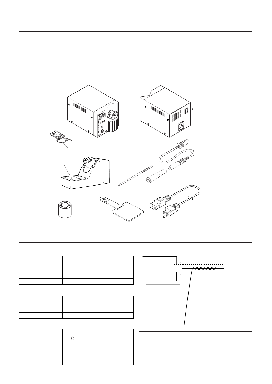
1. PACKING LIST
FM-202 soldering station ................................1
FM-2021 connector assembly ........................ 1
Sleeve .............................................................1
Sleeve stopper ................................................1
Power cord ...................................................... 1
Control card, with chain ..................................1
Control card
Cleaning
sponge
Card chain
Iron holder
FM-202
Soldering station
Tip (not included)
Heat resistant pad ........................................... 1
Tip tray ............................................................1
Iron holder ....................................................... 1
Cleaning sponge ............................................. 1
Instruction manual .......................................... 1
Tips (not included)
ON
OFF
FM-2021 connector assembly
Sleeve
Sleeve stopper
Tip tray
Heat resistant pad
2. SPECIFICATIONS
● FM-202 soldering station
Power consumption
Temperature range
Temperature accuracy
Temperature stability
● Station
Output
Dimensions
(l x w x h)
Weight
● Soldering iron
Power consumption
Tip to ground resistance
Tip to ground potential
Length, less cord
Weight, less cord
Length of cord
1
75 W (Max. 130 W)
200 – 450
±10
See Figure 1.
±5
24 V
178 x 119 x 117 mm
(7.0 x 4.7 x 4.2 in)
2,700 g (5.9 lb.)
70 W (24 V)
< 2
< 2 mV
188 mm (7.4 in.) with 2.4D tip
30 g (0.067 lb./1.07 oz.)with 2.4D tip
1.2 m (4 ft)
C (400 – 840°F)
°
C (±18°F) of set temperature.
°
C (±9°F) at idle temperature
°
Power cord
Accuracy: ±10°C (±18°F)
Set temperature
Stability: ±5°C (±9°F)
Temperature
Time
Figure 1. Temperature accuracy and stability.
NOTE:
This product is protected against electrostatic discharge.
Specifications and design are subject to change without notice.
Page 3
3.
WARNINGS, CAUTIONS, NOTES AND EXAMPLES
Warnings, cautions and notes are placed at critical points in this manual to direct the
operator’s attention to significant items. They are defined as follows:
WARNING: Failure to comply with a WARNING may result in serious injury or
death.
CAUTION: Failure to comply with a CAUTION may result in injury to the
operator, or damage to the items involved. (Two examples are
given below.)
NOTE: A NOTE indicates a procedure or point that is important to the process being
described.
EXAMPLE: An EXAMPLE is given to demonstrate a particular procedure, point or
process.
CAUTION
When power is ON, tip temperatures will be between 200 and 450°C (400 to 840°F).
To avoid injury or damage to personnel and items in the work area, observe the
following:
● Do not insert any foreign substance or incompatible tip into the process gate.
● Do not insert the tip end of the cartridge into the process gate.
● Do not touch the tip or the metal parts near the tip.
● Do not allow the tip to come close to, or touch, flammable materials.
● Inform others in the area that the unit is hot and should not be touched.
● Turn the power off when not in use, or left unattended.
● Turn the power off when connecting the FM-2021 or storing the FM-202.
● Do not remove or damage the bar code sticker.
CAUTION
To prevent accidents or damage to the FM-202, be sure to observe the following:
● Do not use the FM-202 for applications other than soldering.
● Do not allow the FM-202 to become wet, or use it with wet hands.
● Do not modify the FM-202.
● Use only genuine Hakko replacement parts.
● Do not bend or damage the control card. If the card does become damaged, do not force the
card into the station slot.
● Do not strike the iron against hard objects to remove excess solder. This will damage the
iron.
● Remove power and iron cords by holding the plug – not the wires.
● Be sure the work area is well ventilated. Soldering produces smoke.
2
Page 4
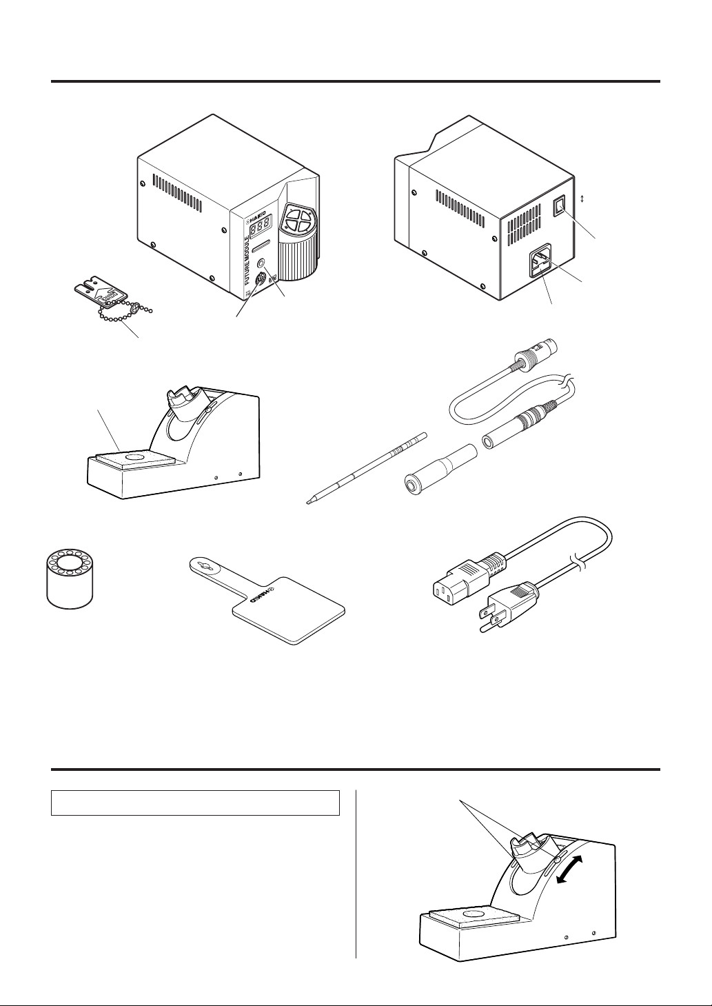
4. PART NAMES
ON
OFF
Power switch
Control card
Cleaning
sponge
Iron holder
Tip tray
Card chain
Receptacle
Heat resistant pad
FM-202
Soldering station
Process gate
Tip (not included)
Power receptacle
Fuse
FM-2021 connector assembly
Sleeve
Sleeve stopper
Power cord
5. INITIAL SETUP
A. Iron holder
1. Adjust the height of the iron holder to suit, as
follows:
i. Loosen the adjusting screws.
ii. Set the iron holder to the desired height.
iii. Tighten the screws.
3
1
Page 5
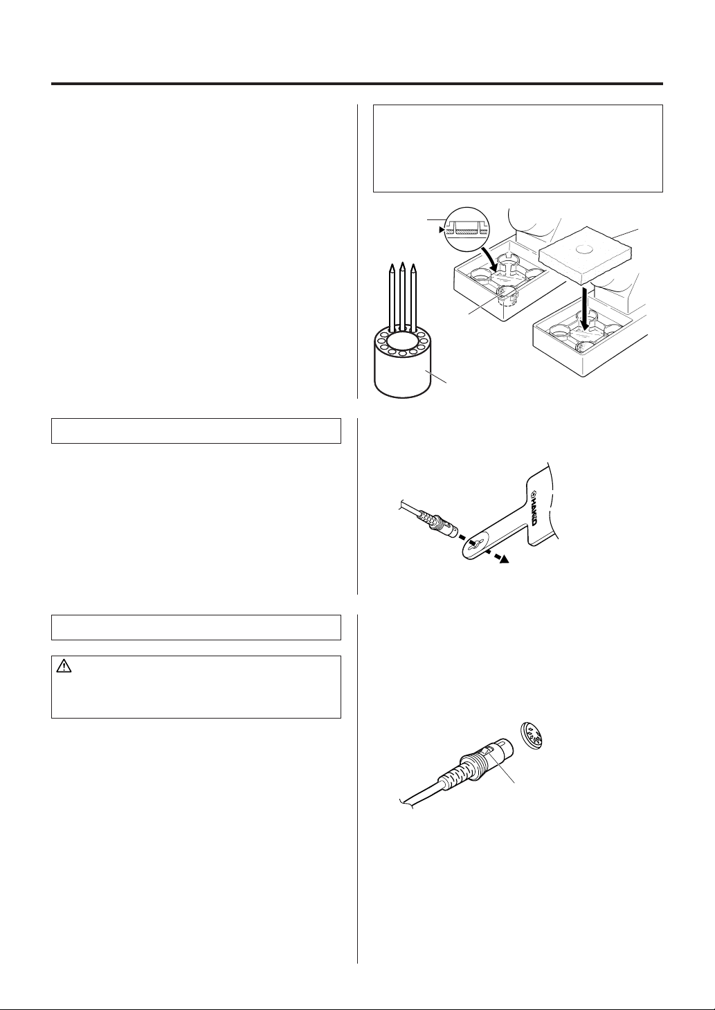
2. Put the small cleaning sponge in one of the
5
four holes in the iron holder base.
3. Add water to the level shown in the accompanying illustration. The small sponge
will keep the large sponge moist through
capillary action.
4. Wet the large cleaning sponge, squeeze it
dry, and put it on the iron holder base.
Procedure 2-4 -ORWet the large cleaning sponge, squeeze it
dry, and put it on the iron holder base.
5. Place the spare tips in the tip tray.
B. Connector cord
Pass the connector cord through the hole in the
heat resistant pad.
NOTE:
Be sure the cleaning sponge is kept CLEAN and DAMP.
A dirty sponge will transfer contaminants to the soldering
tip, reducing thermal efficiency and possibly causing
defective solder joints. A dry sponge will abrade the
soldering tip, reducing its life.
3
2
4
C. Soldering station
CAUTION:
Be sure the power switch is OFF before connecting or
disconnecting the soldering iron cord. Failure to do so
may result in damage to the circuit board.
1. Insert the power cord into the receptacle at
the back of the station.
2. Insert the connector cord into the receptacle
at the front of the station.
3. Plug the power cord into a grounded wall
socket. The FM-202 is protected against
electrostatic discharge and must be
grounded for full efficiency.
When the plug clicks ,
it is fully inserted.
Push the plug in as far as
it will go, and try to remove it
without pressing the release pin.
If it stays in the receptacle
it is properly seated.
Receptacle
4
Page 6
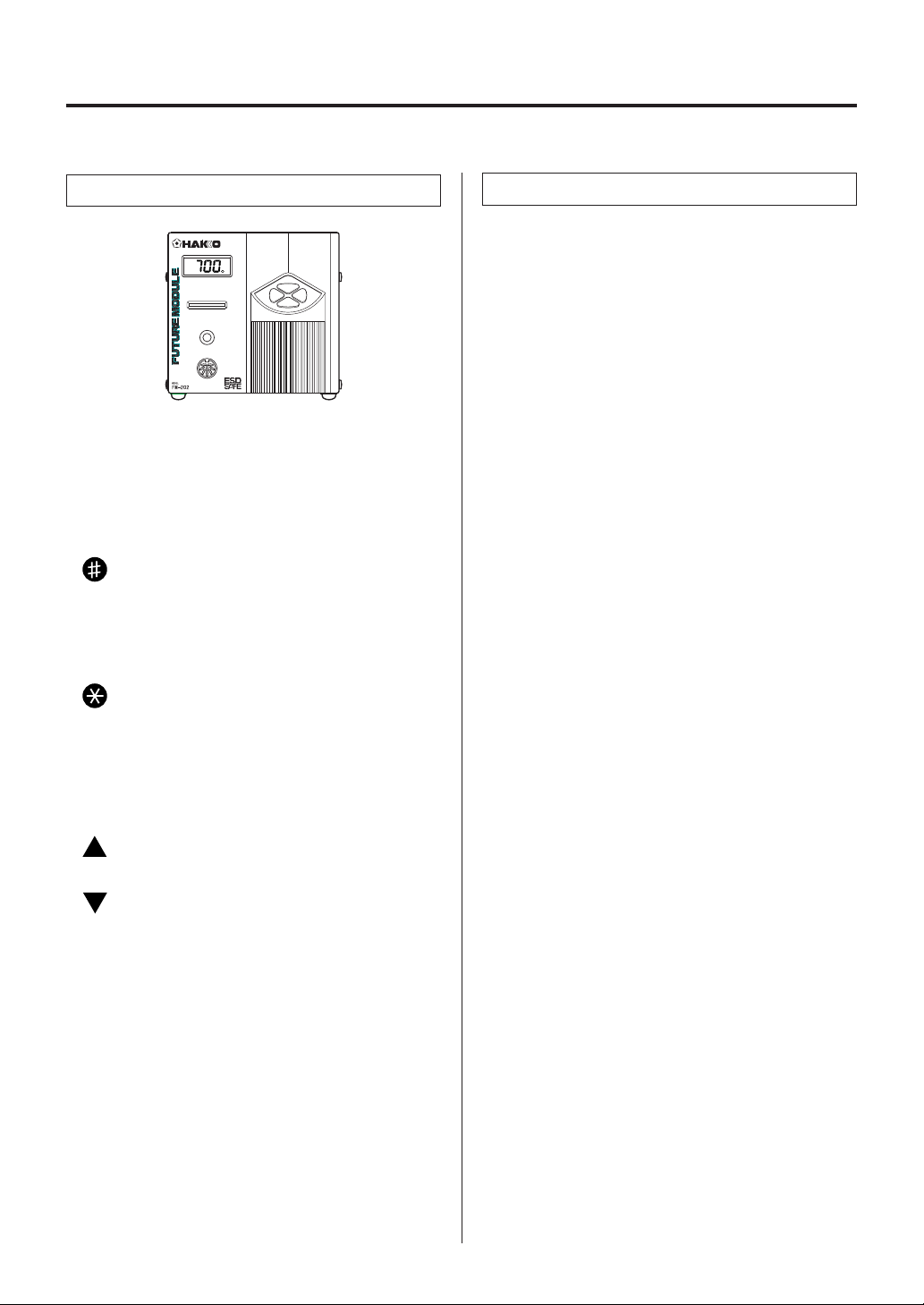
6. OPERATION
Controls and displays
Controls
The front panel of the FM-202 soldering station
has four control buttons, the process gate, the
receptacle, and the card slot. The power switch
is on the back panel.
• Four control buttons:
– Initiates the Tip ID entry mode. When
pressed for less than one second, the
stored Tip ID is displayed. When pressed
for more than one second, the Tip ID
entry mode is activated.
– Initiates the temperature setting mode.
When pressed for less than one second,
the stored temperature is displayed.
When pressed for more than one
second, the temperature entry mode is
activated.
– Increases the value in the appropriate
display window.
– Decreases the value in the appropriate
display window.
Displays
The FM-202 has a three-digit display element.
Depending upon the selected mode, it will
display:
• Normal mode:
Sensor temperature (tip temperature)
• Data entry:
Selected quantity (see ‘data entry procedures’
for exact characteristics)
• Temperature scale:
°C or °F, depending upon selection
• Error detection:
Refer to ‘ERROR MESSAGES’ section
In addition, a single heater lamp will flash when
the station has reached the desired temperature,
indicating that it is ready for use.
An audible buzzer is provided to alert the
operator:
• When the station has reached the set temperature. The buzzer will sound once.
• When the tip is inserted into the process gate,
the buzzer will sound once when the Tip ID
bar code has been read.
• When the low temperature threshold has
been crossed, the buzzer will sound
continuously. The buzzer will shut off once the
sensed temperature returns to the acceptable
range.
• When a foreign substance, an incompatible
tip, or the soldering end of the tip is inserted
into the FM-2021, the display will flash and
the buzzer will sound continuously.
• When the auto power shutoff is activated and
power to the heating element is turned off, the
buzzer will sound three times.
• When the process gate cannot read the Tip ID
bar code, the buzzer will sound three times.
• When a tip insert into the process gate while
the tip is already in the FM-2021, buzzer will
sound irregularity.
• When the tip is properly inserted into the
connector, the buzzer will sound once.
5
Page 7
NOTE:
This procedure must be followed EVERY TIME THE
STATION IS TURNED ON.
1. If a tip is in the connector, remove it; remove
the tip from the sleeve assembly as well.
2. Turn the power switch ON.
Turn the switch ON.
TIN error
Display
Setting temperature
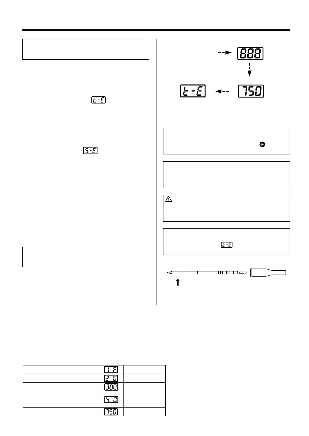
3. The display will show
and the LED on
the connector will flash.
4. Enter Tip ID as follows:
Insert the Tip ID end of the tip into the
process gate until the buzzer sounds once.
Tip ID data are displayed for one second.
The display shows
. The LED indicator
will stop flashing. Indicating that they are
now stored.
(Refer to Appendix A for manual entry.)
5. Inserting the tip:
Hold the head part of the tip and insert the tip
into the sleeve assembly. Push until the
sleeve assembly touches the ring round the
tip; at this point the tip should not be forced
further into the sleeve assembly .
There are no orientation requirements.
NOTE:
Once the tip is inserted into the connector, heat control
begins.
and
LED lamp at the connector begins to flash.
NOTE:
The FM-202 is preset at 750 F . at the factory .
Check the temperature setting by pressing the
The set temperature will be displayed for two seconds.
NOTE:
If the buzzer sounds three times when the tip is inserted
into the process gate, there has been a reading error.
Reinsert the tip.
CAUTION:
Refrain from inserting foreign objects, the wrong end of
the tip, or incompatible tips into the process gate.
Damage may result.
NOTE:
When the power has been cycled, Tip ID is no longer
stored in the station and
as shown at right or in Appendix A.
will flash. Reenter Tip ID
button.
6. When the set temperature is reached, the
buzzer sounds and the heater lamp at the
lower right of the temperature display starts
blinking.
Factory settings
The FM-202 comes from the factory with the
following values preset:
Temperature scale
Auto power shutoff
Low temperature alarm setting
Resetting the supervisor or
operator control setting
Set temperature
Fahrenheit
disabled
300 F
Tip ID controlled
with inserting the
card.
750 F
Hold this part to insert tip into sleeve assembly
and put into the connector.
6
Page 8

● Control card
● Changing the temperature setting
Each FM-202 comes with a small card, which
inserts into the Card slot on the front of the unit.
This card is used when entering data for the
process control function (a temperature value is
to be changed, or data are to be entered). Any
FM-202 card can be used with any FM-202
soldering station.
Example: 700 to 840°F
1. Insert the control card into the slot in the
front of the unit.
• The hundreds digit will begin to flash,
indicating that the unit is in the TEMPERATURE SET mode and data may be
entered.
2. Entering the hundreds digit
• Press the or button to set the
desired value. Only 4, 5, 6, 7, or 8 can be
selected. (In °C mode, 2, 3, or 4 can be
selected.)
When the desired value is displayed,
press the button to enter. The tens digit
will begin to flash.
3. Entering the tens digit
• Press the or button to set the
desired value. Any value from 0 to 9 can
be selected. When the desired value is
displayed, press the button to enter.
The units digit will begin to flash.
CAUTION:
The control card must be inserted into the card slot in the
correct direction for data to be entered.
Insert the card.
Press the or button.
Press the button once.
Press the or button.
Press the button once.
4. Entering the units digit
• Press the or button to set the
desired value. When the desired value is
displayed, press the button to enter.
The desired temperature is now entered
into the system memory and heater
control will begin.
NOTE:
If power is switched off or lost during the execution of this
procedure, no data will be entered. The entire procedure
must be repeated from step 1.
7
Press the button once.
Page 9

When the station is ON and the
control card is in the station, the
data entry procedure is:
● Replacing the tip
Removing and inserting the tip:
Removing the tip: Hold the connector and
pull the tip and sleeve assembly out of the
connector. (If the tip is hot, hold it with the
heat-resistant pad.)
Remove the tip from the sleeve assembly.
Inserting the tip: Hold head part and insert
the tip into the sleeve assembly. Push until
the sleeve assembly touches the ring round
the tip; at this point the tip should not be
forced further into the sleeve assembly.
Put the tip into the connector.
Enter Tip ID for new tip (see page 9).
Insert the new tip firmly into the connector.
(If the tip is not properly inserted, will
be displayed.)
a. Hold the button down for at least one
second.
b. The current temperature setting will be
displayed, then the hundreds digit will begin
to flash. This indicates that the station has
entered the temperature setting mode.
c. Follow steps 1-4 on the preceeding page.
NOTE:
When the button is pressed for less than one second,
the current temperature setting is displayed.
Remove tip from sleeve assembly
Hold this part to insert tip into sleeve assembly
and put into the connector.
CAUTION:
The tip can be very HOT. Use the heat-resistant pad for
handling hot tips, but do not hold the hot portion of the tip,
even with the pad, for a long time.
There are no orientation requirements.
8
Page 10

7. TIP IDENTIFICATION NUMBER
● Entering the Tip ID
Bar codeTip ID
1Y100CB3 01
T7-D24
Part number Serial number
CAUTION:
Do not damage or remove the Tip ID bar code sticker.
Method 1 –
How to read out the bar code of
the tip into the FM-202:
Soldering tips have different thermal characteristics, depending upon their mass, shape, and
surface area. It should be obvious that the tip
temperature at idle will not be the same for a fine
tip as it will be for a heavy chisel tip, although the
set temperature may be the same for each tip. The
FM-202 processor incorporates the ability to
electronically compensate for tip geometry
variations using Tip IDs. Each FM-202 tip style has
a specific Tip ID; whenever a tip is changed, the
Tip ID should be entered into the FM-202 for most
effective process control.
There are two ways to enter Tip ID data into the
FM-202:
See below or page 6 of this manual. This procedure
is the simplest and most common.
See Appendix A of this manual, when the Tip ID is
not readable for some reason.
1. Insert the tip (connector side) into the
process gate in the front of the station.
2. Insert the tip until the buzzer sound once.
The display shows . The LED
indicator will stop flashing. Now the tip
identification number has been stored.
9
NOTE:
When the buzzer sounds three times is reading error, insert
the tip again.
CAUTION:
Do not insert the tip opposite side or other incompatible tip.
CAUTION:
When tip is inserting the FM-2021, the process gate cannot
read the bar code. If a tip insert into the process gate while
the tip is already in the FM-2021, buzzer will sound
irregularity. Remove the tip from the FM-2021 for reading the
Tip ID.
Page 11

8. PARAMETER SETTINGS
● Entering the parameters
(1) °C or °F temperature display
The FM-202 has the following four parameters:
1) °C or °F temperature display selection
2) Auto power shutoff
3) Low-temperature alarm tolerance setting
4)
Supervisor or operator control setting
Once the station enters parameter mode, set the
parameters in the order shown below. Once all the
parameters have been set, normal operation will
be resumed.
1. Turn power OFF.
2. Insert the control card into the card slot in the
front of the unit.
3. Press and hold down the button , and then
turn power ON.
4. The display will show the Tip ID for one second.
Hold the or button down until the display
shows (Celsius) or (Fahrenheit).
When either of these are displayed, the station
is in parameter input mode.
• Pressing either the or button will cause
the display to alternate between or
.
• When the desired scale is displayed, select
by pressing the button. The system will
automatically sequence to auto power shutoff
mode.
(2) Auto power shutoff
This is an optional setting. When it is
activated and the soldering iron is not used
for 30 minutes, the power to the heating
element is shutoff automatically and the
buzzer will sound three times. When the
temperature decreases to 100°C/200°F the
display will show . To resume soldering,
cycle the power switch OFF, then ON. The
power will be turned on automatically if you
hit any button before the temperature
decreases to 100°C/200°F.
To bypass this procedure and continue to
resetting the low temperature alarm
tolerance setting press the button once.
To change the auto power shutoff setting, the
procedure is as follows.
• The display will show or when this
mode is entered.
• Using or button will change and
.
The autopower shutoff is operational only when
is selected.
• Press the button to enter the parameter. This
will store the setting in system memory and the
system will automatically sequence to the low
temperature alarm tolerance setting mode.
NOTE:
Every time the power turn OFF, the Tip ID is not stored to the
station. is flashing. read out bar code or entering the
Tip ID again.
10
Page 12

(3) Resetting the low temperature
alarm tolerance setting
This unique function alerts the operator when
the sensed temperature drops below a set limit.
Should this occur, an error message
will
be displayed, and the buzzer will sound
continuously. When the temperature returns
within the allowable range, the buzzer will stop.
The value is stored in the FM-202 as described
below:
EXAMPLE:
If the set temperature is 650°F and the low temperature
alarm is 100°F, the alarm will trip when the sensed
temperature goes below 550°F.
NOTE:
The threshold limits are: 30 – 150°C; 60 – 300°F.
If a value outside these limits should be entered, the
system will revert to the beginning of the mode, the
hundreds digit will flash, and the procedure must be
restarted.
To bypass this procedure, press the button
three times.
Range of allowable low-temperature alarm
tolerance
For °C: 30 – 150°C
For °F: 60 – 300°F
1. When the station enters low-temperature
alarm tolerance setting mode, the hundreds
digit begun flashing. Enter and store the
value in the same manner as described on
page 7 “Changing the temperature setting.”
2. If you enter a value exceeding the allowable
range shown to the left, you will be brought
back to entering a value in the hundreds
digit. If this occurs, reenter a correct value.
3. Once the value is stored, the system will
automatically sequence to the resetting the
supervisor or operator control setting.
(4) Supervisor or operator control
setting
This mode allows control over the Tip ID data
entry to be assigned to a card-holder.
NOTE:
Whether the card is inserted or not, process gate works.
11
To change the control selection, proceed as
follows:
1. When the mode is entered, the display will
show or
: Tip ID cannot be entered without
inserting the control card.
: Tip ID can be entered without
inserting the control card.
2. Pressing either the or button will
cause the display to alternate between
and .
3. When the desired setting is displayed, select
by pressing button.
The system will exit the parameter setting
mode and begin heater control.
It is now ready for normal operation.
Page 13

9. MAINTENANCE
● Tip maintenance
1. Tip temperature
2. Cleaning
3. After use
4. When the unit is not being used
and the auto power shutoff is not
active.
High temperatures shorten tip life and may
cause thermal shock to components. Always
use the lowest possible temperature when
soldering. The excellent thermal recovery
characteristics of the FM-202 ensure effective
soldering at low temperatures.
Always clean the soldering tip before use, to
remove any residual solder or flux adhering to it.
Use a clean and moist cleaning sponge (provided
with the FM-202) or the Hakko 599 tip cleaner.
Contaminants on the tip have many deleterious
effects, including reduced heat conductivity,
which contribute to poor soldering performance.
Always clean the tip and coat it with fresh solder
after use. This guards against oxidation.
Never allow the unit to idle at a high temperature
for extended periods. This will allow the tip to
become oxidized. Turn the power switch OFF. If
it is to be out of service for several hours, it is
advisable to pull the power plug as well.
5. Inspecting and cleaning the tip
This procedure, if followed daily, will materially
add to tip life.
a. Set the temperature to 250°C (482°F).
b. When the temperature stabilizes, clean the
tip (see 2, above) and check the condition of
the tip. If the tip is badly worn or deformed,
replace it.
c. If the solder plated part of the tip is covered
with black oxide, apply fresh solder, containing flux, and clean the tip again. Repeat
until all the oxide is removed, then coat the
tip with fresh solder.
CAUTION:
NEVER file the tip to remove oxides!
d. Turn the power OFF and remove the tip,
using the heat resistant pad. Set the tip
aside to cool.
e. Remaining oxides, such as the yellow dis-
coloration on the tip shaft, can be removed
with isopropyl alcohol.
12
Page 14

● Checking Procedure
WARNING:
Unless otherwise directed, carry out these procedures with the power switch OFF and the power UNPLUGGED.
■ Check for a broken heater or
sensor
■ Check the grounding line
2
5
3
7
4
1
8
6
■ Checking the connection cord
for breakage
Black
Green
Red
White
Blue
1. Check for a broken heater or sensor
Measure the resistance
across this position.
1Y100CB3
T7-D24
Verify the electrical integrity of the heater and
sensor.
Measure the resistance of the heater and
sensor while at room temperature (15 to 25°C;
59 to 77°F). It should be 8Ω±10%. If the
resistance exceeds these limits, replace the tip.
1. Unplug the connection cord from the station.
2. Measure the resistance value between Pin 2
and the tip.
3. If the value exceeds 2Ω (at room temperature),
perform the tip maintenance described on p.12.
If the value still does not decrease, check the
connection cord for breakage.
1. Remove the soldering tip and the sleeve
assembly.
2. Turn the front piece of the FM-2021 clockwise
and remove the cover.
3. Measure the resistance values between the
connector and the lead wires at the socket as
follows:
Pin 1 – Red Pin 2 – Green
Pin 3 – Black Pin 5 – White
If any value exceeds 0Ω or is , replace the
FM-2021.
■ Replacing the fuse
13
1. Unplug the power cord from the power receptacle.
2. Remove the fuse holder.
3. Replace the fuse.
4. Put the fuse holder back in place.
Page 15

10. ERROR MESSAGES
● Sensor Error
● Low-temperature alarm
tolerance error
EXAMPLE:
350°C (400°C – 50°C)
Set temperature
650°F (750°F – 100°F)
Set temperature
Low-temperature alarm tolerance
OR
Low-temperature alarm tolerance
When there is the possibility that a failure has
occurred in the sensor or heater (including the
sensor circuit), is displayed and the power
is shut down.
NOTE:
The sensor error also occurs if the tip is not inserted
properly.
If the sensor temperature falls below the difference between the current temperature
setting and the low-temperature alarm
tolerance, is displayed and the warning
buzzer sounds. When the tip temperature rises
to a value within the set tolerance, the buzzer
will stop sounding.
EXAMPLE:
Assume that the temperature setting is 400°C/750°F and
the tolerance 50°C/100°F. If the temperature continues to
decrease and finally falls below the value indicated below
while the heating element is on, the displayed value
starts blinking to indicate that the tip temperature has
dropped.
● Heater terminal short circuit
error
● Tip ID error
● Soldering iron error
will flash, and the buzzer will sound
continuously, when the tip is inserted wrong
way round, an incompatible tip is inserted, or a
foreign object has found its way into the
connector.
will flash, and the buzzer will sound three
times, if the process gate cannot read the Tip
ID.
will be displayed if Tip ID has not been
entered.
will be displayed, and the buzzer will
sound continuously, if the connector cord is not
attached to the station OR the wrong soldering
iron is connected.
14
Page 16

11. TROUBLE SHOOTING GUIDE
WARNING:
• Before checking the inside of the FM-202 or replacing parts, be sure to disconnect the power
plug. Failure to do so may result in electric shock.
● The unit does not
operate when the power
switch is turned on.
● The tip does not heat up.
• The sensor error is
displayed.
● Solder does not wet the
tip.
● The tip temperature is
too high.
CHECK : Is the power cord and/or the connection plug dis-
connected?
ACTION
CHECK : Is the fuse blown?
ACTION
CHECK : Is the power cord disconnected?
ACTION
CHECK : Is the tip inserted properly?
ACTION
CHECK : Is the connection cord and/or the heater/sensor broken?
ACTION
CHECK : Is the tip temperature too high?
ACTION
CHECK : Is the tip contaminated with oxide?
ACTION
CHECK : Is the connection cord broken?
ACTION
CHECK : Is the entered tip identification number correct?
ACTION
: Connect it.
: Investigate why the fuse blew and then replace the fuse. If
the cause can not be determined, replace the fuse. If the
fuse blows again, send the unit in for repair.
: Connect it.
: Insert the tip completely.
: See the appropriate section of this manual regarding how
to check the connection cord and/or the heater/sensor for
breakage.
: Set the appropriate temperature.
: Remove the oxide (see “Tip maintenance” on P. 12).
: See “Checking the connection cord for breakage” on
P. 13.
: Enter the correct value.
● The tip temperature is
too low.
● The soldering iron error
is displayed.
15
CHECK : Is the tip contaminated with oxide?
ACTION
CHECK : Is the entered tip identification number correct?
ACTION
CHECK : Is the other soldering iron connected? Or the FM-2021
ACTION
: Remove the oxide (see “Tip maintenance” on P. 12).
: Enter the correct value.
plug disconnected?
: Turn the power switch OFF and connect the FM-2021 or
Hakk 912 soldering iron. Turn the power switch ON.
Page 17

● The low-temperature
alarm tolerance error
occurs frequently.
CHECK : Is the tip too small for the items to be soldered?
ACTION
CHECK : Is the setting value for the low-temperature alarm
ACTION
: Use a tip with a larger thermal capacity.
tolerance too low?
: Increase the setting value.
● Tip ID error is
displayed
● Heater terminal short
circuit error
is
displayed
CHECK : Is the procedure of the entering tip identification number
correct?
ACTION
NOTE:
If reinsert the tip into the process gate and buzzer sounding three times. Try
to insert again or entering the Tip ID by hand operation.
CHECK : Is the tip for FM-2021?
ACTION
NOTE:
This error does not display when not entering the Tip ID.
: Entering correctly.
: Turn the power switch OFF and insert the genuine FM-2021
tip. Turn the power switch ON.
16
Page 18

12. PARTS LIST
NOTE:
Spare or repair parts do not include
mounting screws, if they are not
listed on the description. Screws
must be ordered separately.
● FM-202 Station
Item
No.
1
2
3
4
5
6
7
8
9
10
11
12
13
14
15
16
Part No.
Control card
B2749
Front panel
B2741
Button set for control panel
B2742
P.W.B. (temperature setting,
B2745
display and process gate)
Process gate switch
B2747
Process gate support
B2746
P.W.B. (temperature control
B2744
and connector)
Rubber foot
B2748
Chassis
B2740
Locking spacer
B2757
Transformer
B2743
Power receptacle
B2384
Fuse, 250V-3A
B2761
Power switch
B1084
Cover
B2739
Power cord,
B2419
3 core & American plug
Part Name
16
15
Description
with control panel,
display window and slit
4 each
Set of 4
Set of 2
4 each
with rubber foot
5 each
120V
External tooth
lock washer
Nominal size 4 (2)
13
Pan head screw
M4 x 55 (2)
14
12
Pan head screw with
spring washer M4 x 6 (2)
Binding head screw
M3 x 6 (8)
Spring washer
Nominal size 4 (2)
External
tooth
lock washer
Nominal
size 4
Pan head screw
w/spring washer,
plain washer
M4 x 8 (4)
11
Pan head screw with
spring washer M4 x 6
Tapping screw
Nominal size
3 x 10 (3)
Pan head screw
with spring washer
M3 x 6 (2)
External tooth
lock washer
Nominal size 4
9
Pan head screw
w/spring washer,
plain washer
M3 x 10 (2)
Tapping screw
Nominal size 2.6 x 8 (3)
Tapping screw
Nominal size
3 x 8 (2)
10
5
7
Pan head screw
M1.6 x 8 (2)
Nut
M1.6 (2)
7
Nut M3 (2)
Tapping screw
Nominal size
2.6 x 10 (4)
4
4
Plain washer
Nominal size 3 (2)
4
Nut M2 (2)
Spring washer
Nominal size 2 (2)
6
3
4
2
1
8
Pan head screw
M2 x 25 (2)
1817
Page 19

2
3
2
4
Pan head screw
(M3 x 5) (2)
1
Item No.
1
2
3
4
5
Part No.
FM2021-01
B2750
B2751
B2300
Part Name
Connector assembly
Sleeve
Sleeve stopper
Tip
Heat resistant pad
Description
With O-rings
5
5
Iron Holder
1
3
•
Item No.
Iron Holder Parts
•
Item No.
1~5
1
2
3
4
5
6
Par t No.
C1459
Par t No.
B2753
B2754
A1490
B2405
B2755
B2756
Part Name
Iron holder
Part Name
Iron receptacle
Iron holder base
Cleaning sponge
Rubber foot
Retaining clip
Tip tray
Description
Description
With two screws
(With bottom plate,
rubber foot)
4 ea.
4
19
6
Page 20

13. TIP STYLES
21
115
139
ø5.5
T7-D08 SHAPE-0.8D Chisel T7-D12 SHAPE-1.2D Chisel T7-D16 SHAPE-1.6D Chisel T7-D24 SHAPE-2.4D Chisel
0.5
(0.02)
(0.12)
ø0.8
(0.03)
3
9.5
(0.37)
0.5
(0.02)
4.3
(0.17)
ø1.2
(0.05)
0.5
10
(0.39)
(0.02)
T7-D32 SHAPE-3.2D Chisel T7-D4 SHAPE-4D Chisel T7-D52 SHAPE-5.2D Chisel
(0.008)
30°
R
(0.0
(0.16)
R0.2
(0
0.2
08)
ø4
(0.16)
4
7.5
(0.3)
1.2
(0.05)
T7-LI SHAPE-LI Long Sharp Conical
9.5
(0.37)
T7-C1 SHAPE-1C Bevel
1
.6
.0
6
)
7.9
(0.31)
ø3.2
(0.13)
0.5
(0.02)
1.6
(0.06)
T7-B2 SHAPE-2B Conical
R0.5
(0.02)
10
(0.39)
(0.2)
5
0.5
(0.02)
T7-I SHAPE-I Sharp Conical
T7-JL02 SHAPE-0.2RLB Bent T7-JS02 SHAPE-0.2RSSB Bent
7
.5
(0
.3
)
30°
R0.2
(0.008)
9.3
(0.37)
ø1.6
3.5
(0.14)
(0.31)
R0.2
(0.008)
ø1
ø5.2
8
(0.04)
(0.06)
60
(0.47)
(0.2)
°
10
(0.39)
(0.28)
12.7
(0.5)
12
ø2.4
(0.09)
0.5
(0.02)
4.1
(0.16)
10
(0.39)
T7-B SHAPE-B Conical
R
0
(0.008)
.2
7
(0.3)
7.5
T7-J02 SHAPE-0.2RSB Bent
3
.5
(0
.14
)
30°
R0.2
)
8
0
.0
(0
12
(0.47)
T7-BC1 SHAPE-1BC Bevel
ø1
(0.04)
°
5
4
11.5
(0.45)
Unit: mm (in.)
T7-BCF1 SHAPE-1BC Bevel
(Tinned on the soldering surface only)
ø1
(0.04)
45°
11.5
(0.45)
T7-BCF2 SHAPE-2BC Bevel
(Tinned on the soldering surface only)
ø2
(0.08)
45°
11.5
(0.45)
T7-C4 SHAPE-4C Bevel T7-CF4 SHAPE-4C Bevel
ø4
(0.16)
°
45
11.5
(0.45)
T7-BC12 SHAPE-1.2BC Bevel
(Tinned on the soldering surface only) (Tinned on the soldering surface only)
(0.05)
ø1.2
1.5
60°
(0.06)
15
(0.59)
T7-BC28 SHAPE-2.8BC Bevel
(Tinned on the soldering surface only)
ø2.8(0.11)
60°
3.2(0.13)
17.6
(0.69)
(Tinned on the soldering surface only)
ø4
(0.16)
°
45
11.5
(0.45)
T7-BC15 SHAPE-1.5BC Bevel
ø1.5
(0.06)
60°
1.7
(0.07)
17
(0.67)
T7-BC3 SHAPE-3BC Bevel
ø3
(0.12)
45°
10
(0.39)
T7-KF SHAPE-KF Knife
ø4.6(0.18)
2.4
(0.09)
5°
4
17
(0.67)
T7-BC2 SHAPE-2BC Bevel
ø2
(0.08)
°
45
11.5
(0.45)
T7-BCF3 SHAPE-3BC Bevel
(Tinned on the soldering surface only)
ø3
(0.12)
°
45
10
(0.39)
T7-KL SHAPE-KL Knife
ø4.7
(0.19)
°
1.5
(0.06)
45
11
(0.43)
20
Page 21

T7-KU SHAPE-KU Knife
Unit: mm (in.)
T7-R20 SHAPE-2.0R Slot T7-R23 SHAPE-2.3R Slot T7-R27 SHAPE-2.7R Slot
1.2
(0.05)
ø3
(0.12)
45°
11
(0.43)
1.3
(0.05)
2.0
ø4.5(0.18)
1.6
(0.06)
(0.08)
(0.2)
2.3
(0.09)
ø4.6(0.18)
1.5
5.2
(0.06)
1.8
(0.07)
(0.2)
5.2
5.8
(0.23)
T7-R34 SHAPE-3.4R Slot T7-R48 SHAPE-4.8R Slot T7-1001 SOP5.1 x 4.6 T7-1002 SOP5.1 x 10.4
18.3
(0.72)
1.8
(0.07)
3.4
ø5.8(0.23)
1.8
(0.07)
9.5
11.1(0.44)
3.2
(0.13)
(0.13)
(0.37)
(0.22)
(0.2)
2.3
5.2
(0.09)
T7-1004 SOP9.5 x 15.8T7-1003 SOP9.5 x 18.3 T7-1006 SOP6.9 x 11.4
5.5
15.8
(0.62)
(0.19)
4.8
ø7.2(0.28)
1.8
(0.07)
9.5
11.1(0.44)
3.2
(0.13)
(0.2)
(0.37)
(0.22)
5.1
(0.2)
6.7(0.26)
5.2
4.6
(0.18)
(0.09)
2.3
4.5
(0.18)
10.4
(0.41)
6.7(0.26)
T7-1005 SOP9.5 x 13.2
9.5
(0.37)
11.1(0.44)
13.2
5.5
(0.52)
(0.13)
3.2
5.5
(0.22)
11.4
(0.45)
8.7(0.34)
T7-1009 SOP13.4 x 20.5T7-1008 SOP19.5 x 10.2T7-1007 SOP7.9 x 18.8 T7-1201 PLCC13.6 x 8.5
8.5
(0.33)
9.7
(0.38)
18.8
(0.74)
7.9
9.3(0.37)
3.2
(0.13)
(0.31)
(0.22)
13.4
19.5(0.77)
20.9(0.82)
5.5
10.2
(0.4)
(0.12)
3
6
(0.24)
20.5
(0.81)
(0.53)
14.8(0.58)
4.3
(0.17)
(0.24)
13.6(0.54)
6
14.8
(0.58)
T7-1204 PLCC17.9 x 17.9T7-1203 PLCC12.8 x 12.8T7-1202 PLCC10.3 x 10.3 T7-1205 PLCC23.4 x 17.3
(0.11)
2.7
5.2(0.2)
(0.08)
5.1
(0.2)
2.3
(0.09)
6.9
(0.27)
2.3
(0.09)
2
(0.2)
4.5
(0.18)
4.5
(0.18)
5.5
(0.22)
5
14
12.8(0.5)
(0.55)
5.5
(0.22)
17.9(0.7)
19(0.75)
19(0.75)
17.9(0.7)
5.5
(0.22)
23.4(0.92)
24.6(0.97)
10.3(0.41)
11.5
(0.45)
11.5
(0.45)
10.3(0.41)
5.5
(0.22)
12.8(0.5)
14(0.55)
T7-1206 PLCC22.5 x 16.5 T7-1207 PLCC15.5 x 15.5 T7-1208 PLCC15.8 x 15.8 T7-1209 PLCC8.4 x 8.4
17(0.67)
15.8(0.62)
5.5
(0.22)
22.5(0.89)
23.7(0.93)
17.7(0.7)
16.5(0.65)
5.8
(0.23)
15.5(0.61)
16.7(0.66)
15.5(0.61)
16.7(0.66)
(0.2)
5
15.8(0.62)
17(0.67)
T7-1401 Spatula 15.7
2
(0.08)
15.7
(0.62)
7.2
(0.28)
21
8.4
(0.33)
9.6
(0.38)
8.4
(0.33)
17.3(0.68)
9.6
(0.38)
18.5(0.73)
(0.23)
(0.22)
5.8
5.5
Page 22

14. APPENDIX A
How to enter the tip identification number into the FM-202:
1. Insert the card to unlock the system.
2. Press the button and hold for more
than one second.
• The station will go into Tip ID input mode.
The tens place digit begins to flash. Refer to
the tip identification number marked on the
bar code sticker.
NOTE:
When the button is pressed for less than one second,
the stored Tip ID settings are displayed.
3. Entering a value in the tens place digit
• Using the or button, enter a value in
the tens place digit. When the entered
value is displayed, press the button.
The units digit begins to flash.
4. Entering a number in the units digit
• Perform the same steps used to enter the
value in the tens place digit. After entering
a number in the units digit, press the
button. The display shows will be
flashing. Now the tip identification number
has been stored. The temperature will be
controlled using this tip identification
number.
Example:
When the tip identification number is 07.
Press the button
for at least one second.
Press the button once.
Press the or button.
Press the button once.
NOTE:
When tip is inserting the FM-2021 and changing the Tip
ID, no display but display the setting temperature.
22
Page 23

15. WIRING DIAGRAM
P.W.B/Temperature setting
P.W.B./ Display
P.W.B./
process
gate B
P.W.B./
process
gate A
5
CN5
1
15
CN4
1
CN6
1
Process gate
switch
P.W.B./
Temperature control
11
CN3
6
1
CN1
1
CN9
Connector board
Power switch
Power receptacle
White
Black
1
2
Ground
6
HEAD OFFICE
4-5, SHIOKUSA 2-CHOME, NANIWA-KU, OSAKA, 556-0024 JAPAN
TEL:+81-6-6561-3225 FAX:+81-6-6561-8466
http://www.hakko.com
AMERICAN HAKKO PRODUCTS, INC.
28920 N. AVENUE WILLIAMS VALENCIA CA 91355, U.S.A.
TEL: (661) 294-0090 FAX: (661) 294-0096
Toll Free (800)88-HAKKO www.hakkousa.com
4 2 5 5 6
23
Jan. 2002
MA01085JU020108
 Loading...