

Page 1

SOLDERING TESTER
FG-101B
Instruction Manual
Thank you for purchasing the HAKKO FG-101B Soldering tester.
This product is a soldering iron tester capable of measuring soldering tip
temperature, leak voltage and ground resistance.
Please read the manual carefully
before operating the HAKKO FG-101B.
Please keep this manual readily accessible for reference.
Page 2

Table of Contents
1. PACKING LIST AND PART NAMES .........................................................................................1
2. SPECIFICATIONS ......................................................................................................................2
3. WARNINGS, CAUTIONS AND NOTES .....................................................................................3
4. OPERATION ..............................................................................................................................4
4-1 Initial setup ........................................................................................................................................... 4
4-2 Measurement of tip temperature ........................................................................................................ 5
4-3 Measurement of leak voltage ............................................................................................................. 6
4-4 Measurementofresistancedierencebetweentipandgroundwire ............................................ 7
4-5 Explanation about various functions ................................................................................................ 7
5. MAINTENANCE .........................................................................................................................9
6. REPLACEMENT PARTS/OPTIONS ........................................................................................10
Page 3
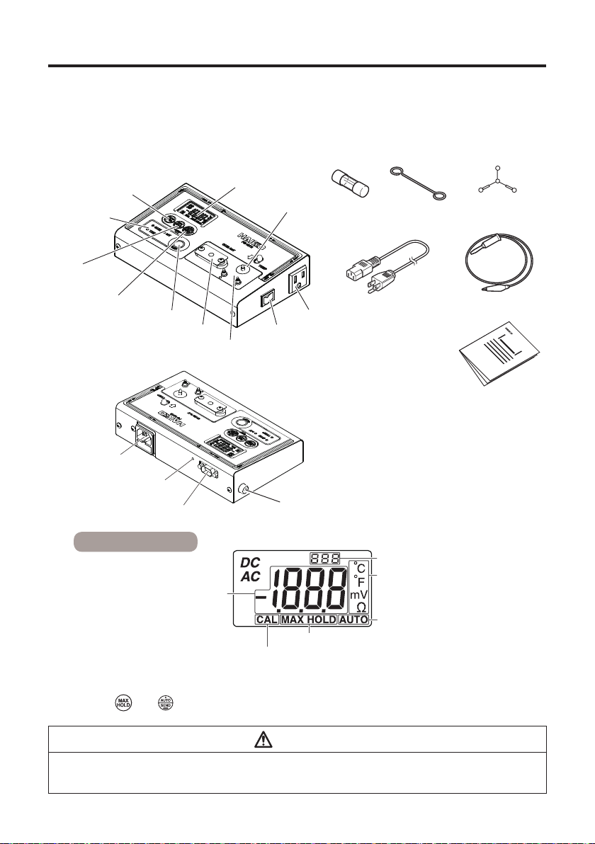
1. PACKING LIST AND PART NAMES
Please check that all items listed below are included in the package.
HAKKO FG-101B ............................................1
Fuse.................................................................1
Conductive wire ...............................................1
Sensor (qty 10) ................................................1
AUTO ZERO button
Mode display
MAX HOLD
button
AUTO/SEND
button
HAKKO FG-101B
Inlet
Infrared output part
DATA I/O connection (9 pins)
SELECT button
Conductive plate
LCD
Blind plate
Power switch
Protective plate
Ground clip ......................................................1
Power cord ......................................................1
Instruction manual ...........................................1
Fuse
Conductive
Sensor
wire
Power receptacle
Power cord
Ground clip
Instruction manual
Ground terminal (GND)
SYSTEM TESTER
FG-101B
Display contents
*2
Display temperature, leak voltage and
*1 This alarm indicates sensor burnout.
If this alarm occurs, replace the sensor.
*2 When the
is reset.
tip to ground resistance/
Burnout alarm
(Display of "-1" indicates burnout.
and buttons are held pressed simultaneously for a long time (1 sec or longer), the count
*1
Temperature measurement count
°C/°F/mV/Ωdisplay
AUTO HOLD function
MAX HOLD function
Calibration
CAUTION
Do not use this product for a soldering iron which is not grounded.
Connect this product to a power receptacle equipped with a ground terminal and ground it before use.
1
Page 4

2. SPECIFICATIONS
Model name HAKKO FG-101B
Temperature Resolution 1˚C 1°F
Measurement range 0 - 700˚C
Measurement
tolerance
±3˚C (between 300 and 600˚C)
±5˚C (other than above)
Sensor K(CA) thermocouple
Voltage Resolution 0.1mV
Measurement range 0 - 40 mV (AC)
Measurement tolerance
±(5% of reading +1 digit)
Resistance Resolution 0.1Ω
Measurement range 0 - 40Ω
Measurement tolerance
±(5% of reading +1 digit)
Display LCD display 3-1/2 digits
*2
Burnout
MAX HOLD function Refer to "MAX HOLD Function" (page 7) in "4-5
Explanation about various functions".
AUTO HOLD function Refer to "AUTO HOLD Function" (page 8) in "4-5
Explanation about various functions".
Temperature
000 to 999 times
measurement count
function
Power consumption 100V : 3.2W 100 - 110V : 3.6W
Outline dimensions 211(W) × 53(H) × 126(D) mm
Weight 0.95 kg
Usable temperature/humidity range 0 to 40˚C, Max. 80%RH, without condensation
Environmental conditions Applicable rated pollution degree 2
*1 Temperature sensors (191-212) can only be used to measure temperatures below 500°C (932°F). To
measure higher temperatures, use an appropriate temperature probe (see"6. REPLACEMENT PARTS/
OPTIONS").
*2 If the temperature sensor is not attached or is disconnected, "Burnout" will appear. If the temperature sensor
is disconnected, replace it with a new one. In addition, if a value out of the temperature range is detected.
"Burnout" will also appear.
*1
32 - 1300°F
±6
±10°F (other than above)
120V : 3.2W 220 - 240V : 3.6W
(According to IEC/UL61010-1)
*1
(between 572 and 1112°F)
°F
NOTE
Please note that the specications and appearance are subject to change without prior notice.
2
Page 5

3. WARNINGS, CAUTIONS AND NOTES
In this manual, items requiring caution are classied into 2 categories, "WARNINGS" and
"CAUTIONS", as dened below. Please make sure to understand these items before reading
the main text.
WARNING :
CAUTION : Failure to comply with a CAUTION may result in injury to the operator, or damage
NOTE : Indicates important steps or items in the procedure being explained.
Be sure to observe the following warning items.
The unit is for a counter or workbench use only.
This appliance can be used by children aged from 8 years and above and persons with reduced
physical, sensory or mental capabilities or lack of experience and knowledge if they have been
given supervision or instruction concerning use of the appliance in safe way and understand the
hazards involved.
Children shall not play with the appliance.
Cleaning and user maintenance shall not be made by children without supervision.
Be sure to observe the following warning items, for which failure to do so may cause
accidents or malfunctions.
This unit is for indoor use only.
When using the thermometer to measure the temperature of the soldering iron tip or desoldering
nozzle, pay great attention to the temperature of the tip or nozzle since it will be as high as 200 to
450°C (392 to 842°F). Careless handling of such a hot object may result in a burn or re.
Do not modify this product.
Do not get this product wet or use it with wet hands.
Be sure to unplug the power plug before internal inspection or replacement of parts. Failure to do so
may cause an electric shock.
Use HAKKO genuine parts as replacement parts.
When inserting or unplugging the power plug, do so while holding the plug, not the cord.
Do not perform dangerous actions.
Failure to comply with a WARNING may result in serious injury or death.
to the objects involved.
WARNING
CAUTION
3
Page 6

4. OPERATION
4-1 Initial setup
Attach the included sensor.
1.
1) Slide the slide button. The slide pin
will move toward the terminal.
Slide pin
Slide button
Conductive plate
2) Attach the sensor with the slide pin
moved toward the terminal.
3) Attach the sensor having a red mark
to the red-colored terminal and the
sensor having a blue mark to the
blue-colored terminal.
Insert the power plug into the power
2.
receptacle and turn on the power switch.
1) Be sure to connect the main body
power cord to a two-pole grounded-
type receptacle.
2) The power receptacle of the HAKKO
FG-101B main body supplies power
only when the power switch is turned
on.
Terminal
CAUTION
Since the sensor is made of ultra-
thin (Ø0.2) K thermocouple, pressing
the sensor strongly may cause it to be
disconnected. Handle it with care.
4
Page 7

4-2 Measurement of tip
temperature
1) Press the SELECT button to set the
mode to "TEMP".
New solder
2) Apply a new coat of solder on
the tip and touch it on the sensor
measurement part (See the gures at
right.)
NOTE:
When measuring, apply a new coat of solder on the tip. This action is required to ensure
that the conductive plate comes in rm contact with the tip.
CAUTION
• Since the main body is partially
made of resin, be careful not to
touch the tip to the main body. In
addition, also be careful not to
touch the tip to the terminal or the
slide pin.
• Although the measurement point
of the sensor undergoes special
treatment, it will deteriorate
gradually due to repeated
measurements. In order to measure
the temperature correctly, if the
measurement point is worn out,
replace the sensor with a new
one. The reference number for
sensor replacement is approx. 50
measurements.
Do not measure the temperature by applying
hot air (HAKKO FR-811, etc.) directly to the
HAKKO FG-101B. If hot air is applied directly,
the HAKKO FG-101B will be damaged.
Tip
Measurement
point
CAUTION
• When ux is stuck on the terminal,
wipe it o with alcohol. (Do not use
thinner or benzin for wiping.)
• Read the values when the display
temperature is stable.
5
Page 8

4. OPERATION(continued)
4-3 Measurement of leak voltage
CAUTION
• Before measuring the voltage or resistance, be sure to connect the main body
power cord to a two-pole grounded-type receptacle.
• If values exceeding specied ones are displayed as results for voltage or
resistance, check the tip and attaching screws of the soldering iron for looseness
and take another measurement.
1) Plug the power plug of the soldering
iron to be measured into the power
receptacle the HAKKO FG-101B
main body.
2) Wait until the tip reaches the
set temperature. If the soldering
iron temperature is variable, set
temperature to maximum.
3) Press the SELECT button and
change the mode to "mV".
4) Press the
Refer to " AUTO ZERO function"
(page 8) in "4-5 Explanation about
various functions".
5) Clean the tip and apply a new coat of
solder on the tip.
6) Apply a coating of solder to the center
of the conductive plate and heat it
until a good soldering wet condition is
achieved.
7) When the display temperature is
stable, read the values.
button.
NOTE :
During measurement of leak voltage, even
when the tip is not applied to the conductive
plate, values are displayed; however, this is
not a malfunction of the product. In addition,
when values out of measurement range are
detected, burnout will be displayed, and this is
also not a malfunction.
NOTE :
If solder can't wet easily on the conductive plate due to low tip temperature or because of
the tip having small thermal capacity, use the included conductive wire.
Replacement method
Remove the 2 screws attaching the conductive plate, replace the conductive plate with the
conductive wire, and then attach the conductive wire with the removed screws.
6
Page 9

4-4 Measurement of resistance dierence between tip and ground wire
1) Plug the power plug of the soldering iron to be measured into the power receptacle the
HAKKO FG-101B main body.
2) Wait until the tip reaches the set temperature. If the soldering iron temperature is variable,
set temperature to maximum.
3) Press the SELECT button and change the mode to "OHM".
4) Press the
button. {Refer to " AUTO ZERO function" (page 8) in "4-5 Explanation
about various functions".}
5) Perform the measurement in the same procedure as "4-3 Measurement of leak voltage".
4-5 Explanation about various functions
HAKKO FG-101B can use the following functions.
MAX HOLD function (Temperature
measurement only)
Quickly pressing the button will cause "MAX
HOLD" to be displayed at the bottom of the
screen. As long as "MAX HOLD" is shown, the
maximum temperature will stay displayed.
Operation method
Pressed quickly (less than one second)
"MAX HOLD" is displayed at the bottom
of the screen.
Pressed quickly (less than one second)
("MAX HOLD" is displayed )
By pressing the button quickly, the
displayed value will be reset and the
maximum temperature after pressing the
button will be displayed.
Pressed for a long time (1 second or
longer)
The MAX HOLD function will be released
and the product will return to normal
display.
MAX HOLD
Press the
less than 1 second
MAX HOLD
Press the
less than 1 second
MAX HOLD
Max. temperature is updated.
button for
Press the button for
1 second or more
button for
MAX
"MAX HOLD"
disappears
indicating the
function is
cancelled.
CAUTION
Turning o the power always cancels the
MAX HOLD function.
The MAX HOLD function can only be used
during the temperature measurement.
HOLD
7
Page 10

4. OPERATION(continued)
受信部
AUTO ZERO function
AUTO ZERO function is necessary for measureing voltage (mV) and resistance (OHM).
Pressing the
button displays "counting": 0.0.0 → 0.0 → 0.
Wait until the normal display appears.
Correction values from AUTO ZERO are recorded in the main body. Even after the power is
turned o, the correction values are still available in later measurement sessions.
Before using this function, it is necessary to cancel the "AUTO HOLD" displays.
AUTO HOLD function
When the button is pressed quickly (less than one second), "AUTO" will blink at the lower
right of the LCD.
While "AUTO" is blinking, touch the soldering iron tip to the sensor. (temperature)
While "AUTO" is blinking, touch the soldering iron tip to the conductive plate. (mV, OHM)
"AUTO" will stop blinking and stay lit after a certain amount of time, and the xed
measurement result will be displayed.
Even after the xed result is displayed, applying the tip to the sensor or the conductive plate
will enable the AUTO HOLD function to work again.
Each time the
The AUTO HOLD function does not assume the measurement by temperature probes such
as the hot air.
button is pressed, the AUTO HOLD function toggles between ON and OFF.
Data send function (infrared)
Press the button for longer than one second.
Temperature data will be sent by infrared output
from the upper part of the HAKKO FG-101B. The
temperature display will blink during sending.
Receiving
受信範囲
scope
Receiver
Infrared output
赤外線出力方向
direction
Infrared output part
赤外線出力部
The temperature send function can send data only
to machines capable of receiving the data.
Only xed values can be sent.
In order to send xed values, the AUTO HOLD function or MAX HOLD function can be used
for temperature measurements and the AUTO HOLD function can be used for voltage or
resistance measurements.
Make sure the HAKKO FG-101B infrared output part is facing and within the reception range
of the receiver.
Count function
When a sensor detected a sudden temperature
rise more than 100 degrees Celsius, the value of
the thermometry count Increases.
When resetting the count number, push the
button and the
button for more than one
second at the same time.
8
Temperature measurement count
Page 11

Data communication function (DATA I/O)
Connecting an exclusive cable adaptor module (option) to the DATA I/O connector on the
upper part of the HAKKO FG-101B enables communication to applicable stations such as the
HAKKO FN-1010, etc. (See the gure below) Data communication by infrared will be disabled
during communication by DATA I/O. Pressing the
data. Only xed values can be sent.
In order to send xed values, the AUTO HOLD function or MAX HOLD function can be used
for temperature measurements and the AUTO HOLD function can be used for voltage or
resistance measurements. Measurement and data acquisition can be performed smoothly
using the functions of connected stations.
C5055
Adapter module
button for 1 second or longer sends
HAKKO
FN-1010
Ground terminal (GND)
When using a type of soldering iron that is grounded with an alligator clip, connect the clip to
the GND terminal.
DIN cable RS232C cable
HAKKO
FG-101B
5. MAINTENANCE
Maintenance and Calibration
• To replace the conduction plate, remove the set screws.
• The life of the temperature sensor will vary depending on the temperature at which
measurements are made and the type of solder and ux being used. In general, temperature
sensors can be used for 50 measurements. Replace the sensor as soon as the measuring
point wears out.
• HAKKO can calibrate the instrument for a nominal fee. Please contact your dealer for further
information.
CAUTION
Pressing the POWER button while holding the button pressed changes the
temperature unit between ˚C and ˚F.
9
Page 12

6. REPLACEMENT PARTS/OPTIONS
● HAKKO FG-101B
Item No. Part name Specications
B2419 Power cord/3 core & American plug 120V USA
B2421 Power cord/3 cored wire with no plug
B2422 Power cord/3 core & BS plug India
B2424 Power cord/3 core & European plug 220V KC 230V CE
B2425 Power cord/3 core & BS plug 230V CE U.K.
B2426 Power cord/3 core & Australian plug
B2436 Power cord/3 core & Chinese plug
B3508 Power cord/3 core & American plug
B3550 Power cord/3 core & SI plug
B3616 Power cord/3 core & BR plug
B1752 Conduction Plate
B1754 Ground Clip
B1950 Conduction Wire
B1258 Fuse/250V-3.15A
B2468 Fuse/125V-5A
191-212 Sensor/Lead free qty 10
● Optional Parts
Item No. Part name Specications
A1310 Temperature probe for soldering pot
C1541 Temperature probe for hot air With sensor A/B
CX1002 Temperature probe for robot
A1556 Sensor A
A1557 Sensor B
HEAD OFFICE
4-5, Shiokusa 2-chome, Naniwa-ku, Osaka 556-0024 JAPAN
TEL:+81-6-6561-3225 FAX:+81-6-6561-8466
http://www.hakko.com E-mail:sales@hakko.com
OVERSEAS AFFILIATES
U.S.A.: AMERICAN HAKKO PRODUCTS, INC.
TEL: (661) 294-0090 FAX: (661) 294-0096
Toll Free (800)88-HAKKO
4 2 5 5 6
http://www.hakkousa.com
HONG KONG: HAKKO DEVELOPMENT CO., LTD.
TEL: 2811-5588 FAX: 2590-0217
http://www.hakko.com.cn
E-mail:info@hakko.com.hk
SINGAPORE: HAKKO PRODUCTS PTE LTD.
TEL: 6748-2277 FAX: 6744-0033
http://www.hakko.com.sg
E-mail:sales@hakko.com.sg
.hakko.com
© 2019 HAKKO Corporation. All Rights Reserved.
MA03048Ib190507
2019.5
 Loading...