

Page 1
Part Number : AC-8888-131
Par
Domestic Air Conditioner
SERVICE MANUAL
Models
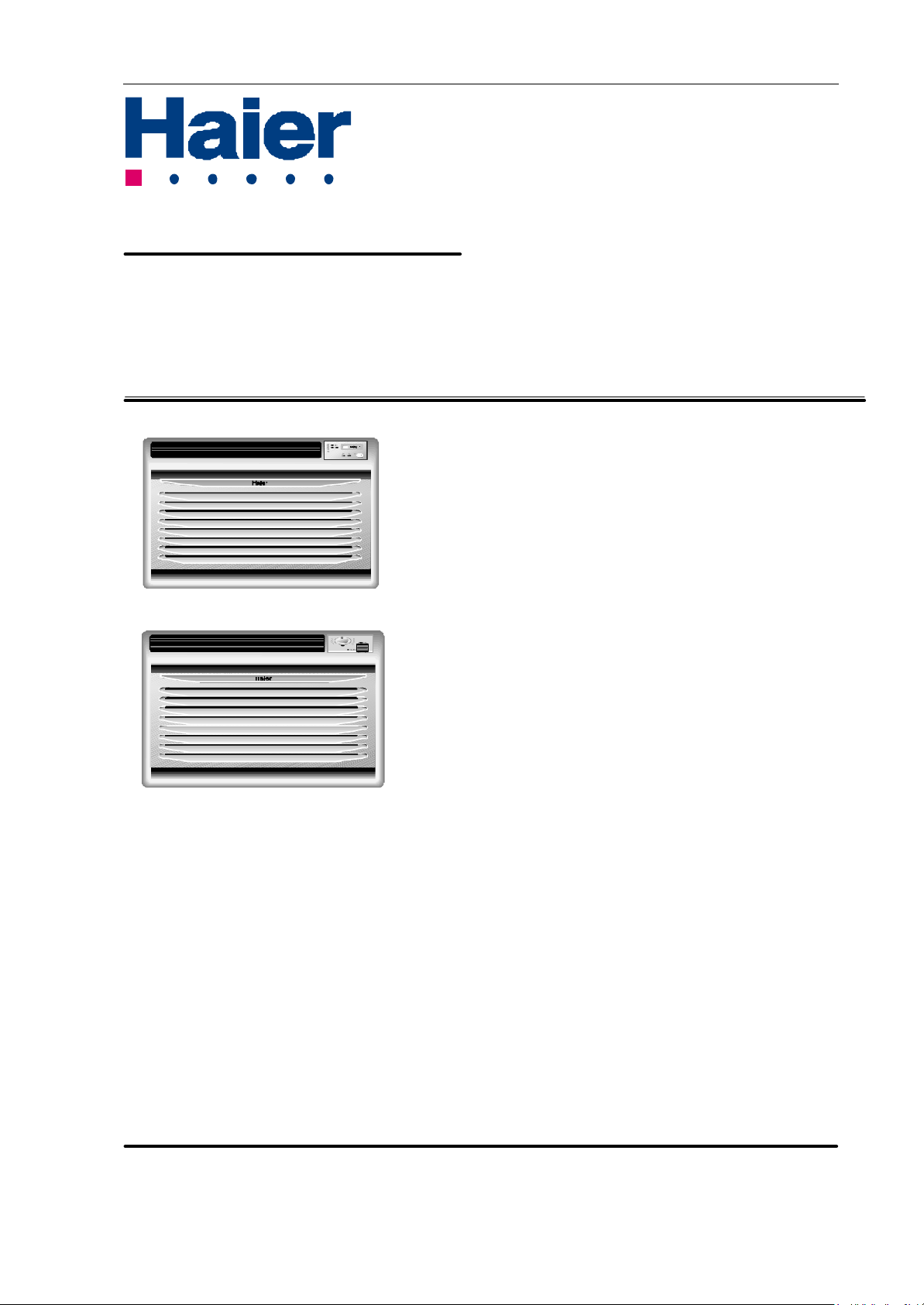
HWR05XC5
HWF05XC5,HWF05XC6
l Features
l Top-Discharge Air Flow
l Ultra Quiet Operation
l Safty Power Cord
l EnvicoCleanTMCoil
l Easy-Access Washable Filter
Serial Number: V ersion:00.00 Edition: 2004-11-16
Page 2

Domestic Air Conditioner Model: HWR05XC5
HWF05XC5
Content
1、 Product Code Illumination And Series introduction ---------------------------- 2
2、 Specifications -------------------------------------------------------------------------------- 3
3、 Safety and Precaution ----------------------------------------------------------------------4
4、Warning and Cautions ----------------------------------------------------------------------5
5、Net Dimention ---------------------------------------------------------------------------------6
6、Installation and Accessory Parts -------------------------------------------------------7
7、Parts and Functions -----------------------------------------------------------------------13
8、Abnormity Diagnose -------- ---------------------------------------------------------------14
9、System Flow Chart -------------------------------------------------------------------------15
10、Circuit Diagram ----------------------------------------------------------------------------16
11、Maintenance Service and Trouble Shooting -----------------------------------17
12、Wiring Diagram --------------------------------------------------------------------------20
13、
1
Page 3
Domestic Air Conditioner Model: HWR05XC5
HWF05XC5
Product Code Illumination And Series Introduction
1.Model identification:
H W
A B C D E F G
A: Abbreviation of Haier
B: Abbreviation of Window
C: R-Remote Control
F-Mechanical Control
D: Nominal cooling capacity(BTU/h) with the first two numbers based on one
thousand unit
E: The type of power supply
X: 115V/60HZ
V:208/220V/50HZ
F: Function code
C-Cooling only
H-Heating pump
E-Electric aided heating
G: Design code
Examples:
HWR05XC5
It represents remote control window air conditioner. Cooling capacity is 5000BTU/h and
the power supply is 115V /60Hz.
2.Standard situation/conditions
No. Operating condition
1 Nominal cooling 26.7 19.4 35 23.9
2 Nominal heating / / / /
Nominal electrical
3
heating
Indoor air state outdoor air state
D.B.℃ W.B.℃ D.B.℃ W.B.℃
/ / / /
2
Page 4
Domestic Air Conditioner Model: HWR05XC5
HWF05XC5
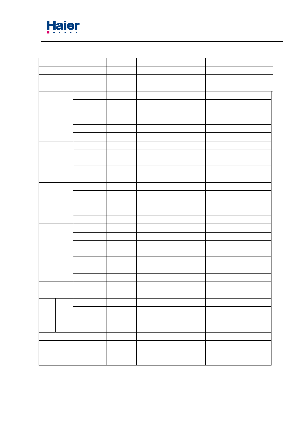
Specifications:
Item UNIT HWR05XC5 HWF05XC5
Cooling capacity BTU/h
Heating capacity BTU/h
Power supply
Power input
Cooling
Heating
Sound Level
Case
Packaging
dimensions
Weight
Compressor
Pressure
Refrigerant
Type
Fan
Fan
speed
Air volume CFM
Moisture removal M3/h
Exchanging pipe type/ diameter mm Evaporator
Fin material
Running current
EER
Power input
Running current
COP
Indoor side dB(A)
Outdoor side dB(A)
Height
Width
Depth
Height
Width
Depth
Net kg
Gross kg
Type
Model
Running cap. for
comp.
Starting method
Heating side MPa
Cooling side MPa
Model
Charge kg
indoor unit
outdoorunit
indoor unit r/min
outdoorunit r/min
W 515 515
A 4.8 4.8
BTU/(hW)
W / /
A / /
BTU/(hW)
mm
mm
mm
mm
mm
mm
μF
1085±30/895±50
1085±30/895±50
35uf/4uf/ 250VAC
Hydrophile aluminum foil Hydrophile aluminum foil
5000 5000
/ /
1PH/115V/60Hz 1PH/115V/60Hz
9.7 9.7
/ /
/ /
/ /
285 285
440 440
340 340
327 327
502 502
386 386
18 18
20 20
Rotate
SD074SW
Acentric fan
Axial fan Axial fan
:ф7condenser:ф7
PSC PSC
380 380
170 170
R22 R22
0.3 0.3
210 210
1.8ⅹ10-3 1.8ⅹ10-3
35uf/4uf/ 250VAC
Evaporator
Rotate
SD074SW
Acentric fan
1085±30/895±50
1085±30/895±50
:ф7condenser:ф7
3
Page 5
Domestic Air Conditioner Model: HWR05XC5
HWF05XC5
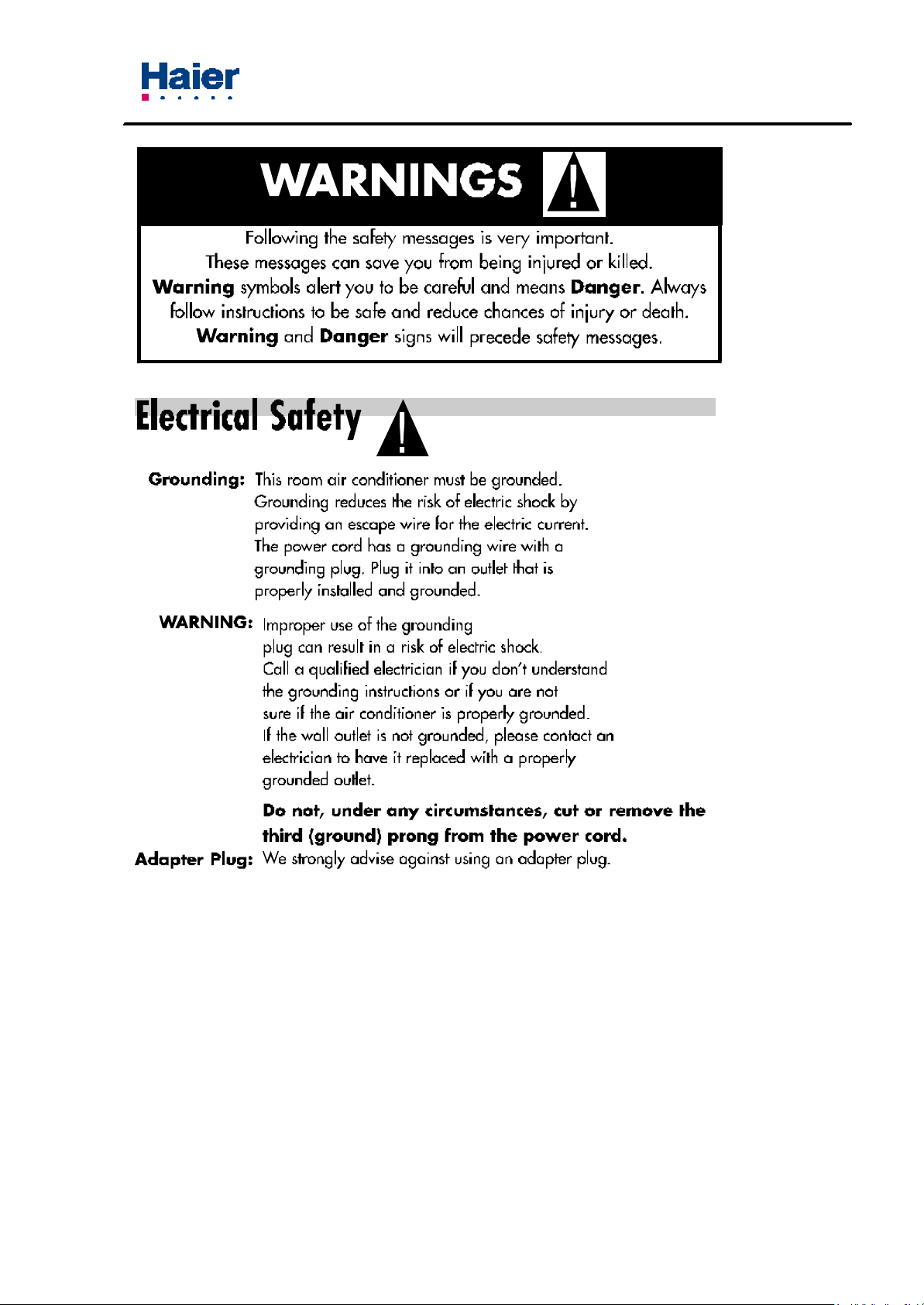
Safety and Precaution
Warning and Cautions
4
Page 6
Domestic Air Conditioner Model: HWR05XC5
HWF05XC5
Important:
T est power plug before each use:
1. Press “reset “button.
2 . Press “test “button, unit should trip.
3. Press “reset” button again for use .
Do not use if above test fail.
In the event this device trips , the cause of the malfunction is to
be corrected before further use of the device .
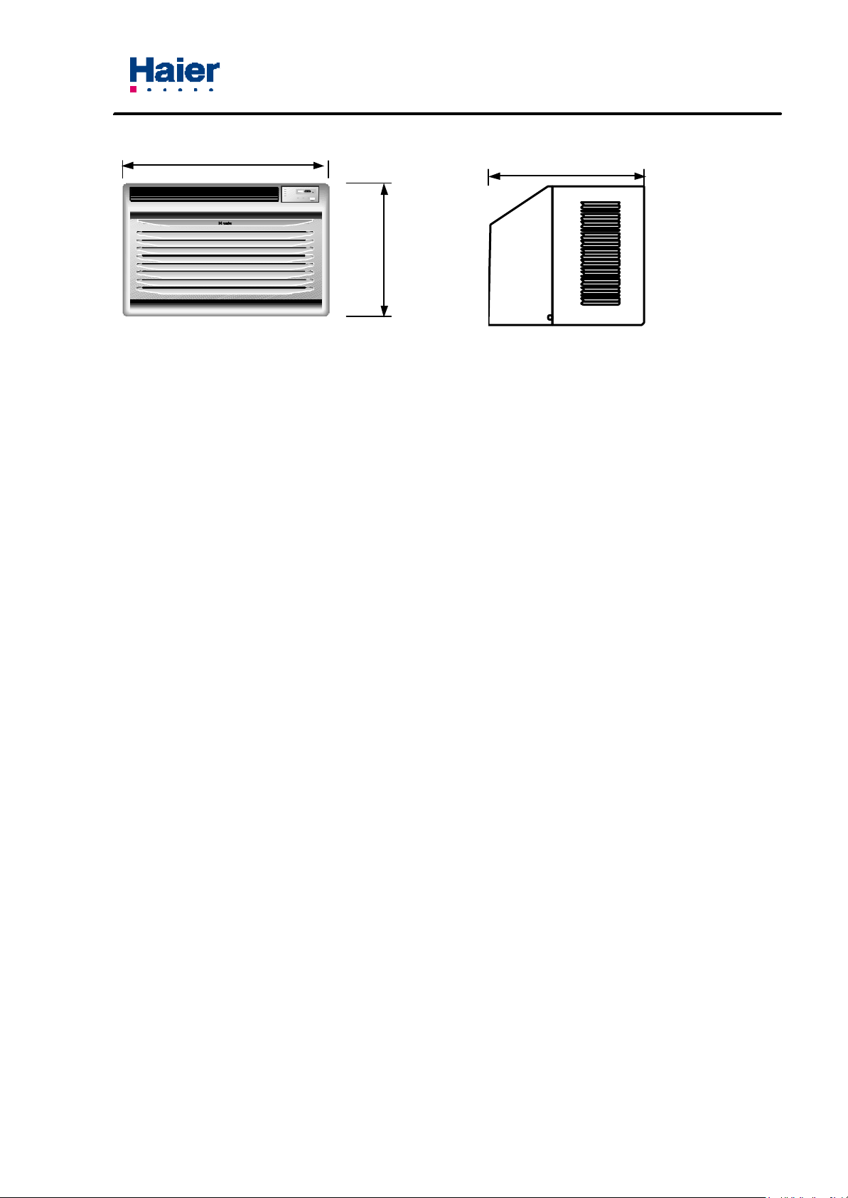
Net Demention
5
Page 7
Domestic Air Conditioner Model: HWR05XC5
HWF05XC5
440
285
340
6
Page 8

Domestic Air Conditioner Model: HWR05XC5
HWF05XC5
Installation and Accessory Parts
7
Page 9

Domestic Air Conditioner Model: HWR05XC5
HWF05XC5
Installation and Accessory Parts
wood screws 31/32"
window seal gasket
short screws 13/32"
Model: HWF05XC5
top rail
short screws 13/32"
wood screws 31/32"
window seal gasket
Model: HWR05XC5
O N/OFF
MODE SP EED TI MER
TEMP/TIME
Remote
control
top rail
“CR2025“ battery
8
Page 10

Domestic Air Conditioner Model: HWR05XC5
HWF05XC5
Installation and Accessory Parts
4
7 65
3
8
S PE ED
2
9
HI
L OW1
10
MIN
M AX
C OO L
C OO LF AN O NLY
P O W ER
O N O FF
W ai t 3 M inu tes Bef oreRe sta rtin g
ASSEMBLE
CURTAINS/TOP RAIL
Install top rail with 3 short
screws13/32".
Insert the side curtains into the
top and bottom rails of the air
conditioner . Fasten the curtains
to the unit with 8 short screws
13/32".
HWF05XC5,HWR05XC5
31
1
32
5
11
8
13
11
16
7
34
16
15
20
32
7
11
16
5
17
16
13
13
32
9
Page 11

Domestic Air Conditioner Model: HWR05XC5
HWF05XC5
Installation and Accessory Parts
2
1. This unit is designed for installation in standard double hung windows
with actual opening widths of 21 to 35 . The upper and lower sash
must open sufficiently to allow a clear vertical opening of 12 from the
bottom of the sash to the window stool.
2. If storm window presents interference, fasten a 2 wide wood strip(not
included) (OUTER SILL) to the inner window sill across the full width of
the sill. The wood strip should be thick enough to raise the height of
the window sill so that the unit can be installed without interference by
the storm window frame (STORM WINDOW FRAME) or wood strip
(OUTDOORS) to help condensation to drain properly to the outside.
3. Install a second wood strip (approximately 6 long by 3/2 wide and
same thickness as first strip) in the center of the outer sill flush against
the back off the inner sill. This will raise basepan angle .
4. If the distance between STORM WINDOW FRAME and WOOD STRIP
MOUNTED ON TOP OF INNER SILL is more than 1 , two of wood
strip are not necessary.
LOCATING UNIT IN
WINDOW
Open the window and mark center line on the
center of the inner sill.
Install the basepan angle behind the inner window sill, with
the short side of basepan angle as shown. Use the 2 short
screws13/32" provided.
The basepan angle helps to hold unit securely in place.
Be sure to place basepan angle edge flush against back
of inner sill.
INNER
SILL
I
N
D
O
O
R
S
WOOD STRIP
MOUNTED ON
TOP OF INNER SILL
INNER
SILL
I
N
D
O
O
R
S
1 MAX.
WOOD STRIP
FOR BASEPAN
ANGLE
ATTACH BASEPAN
ANGLE
OUTER
SILL
3/4 CLEARANCE
STORM
WINDOW FRAME
OUTER
SILL
O
U
T
D
O
O
R
S
O
U
T
D
O
O
R
S
INNER SILL
INDOOR SIDE
CENTER LINE
OUTER SILL
SHORT SIDE
OUTSIDE
INNER SILL
7,5
BASEPAN ANGLE
10
SHORT SCREW13/32"
CENTER LINE
INSIDE
7,5
Page 12

Domestic Air Conditioner Model: HWR05XC5
HWF05XC5
Installation and Accessory Parts
INSTALL THE AIR CONDITIONER
IN THE WINDOW
Carefully lift the air conditioner and slide it into the open
window. Make sure the bottom guide of the air conditioner
drops into the notches of the basepan angle.
While steadying the air conditioner ,carefully bring the
window sash down behind the upper guide of the air
conditioner.
INSTALL THE SEAL GASKET
AND SASH LOCK
Extend the side curtains to fill the
window opening using 4 wood screws
31/32" to secure them.
Cut the seal gasket to the window
width. Stuff the sash seal between the
glass and the window to prevent air
and insects from getting into the room.
Fasten the basepan angle, using a
short screw13/32".
BASEPAN ANGLE
SHORT SCREW13/32"
WOOD SCREW31/32"
WINDOW FRAME
UPPER GUIDE
ABOUT 1/4
BOTTOM GUIDE
BASEPAN ANGLE
WINDOW SEAL GASKET
11
Page 13

Domestic Air Conditioner Model: HWR05XC5
HWF05XC5
Parts and Functions
easy
access
f ilters
2-way
airflow
co ntrol
panel
TIME ON
TIME OFF
HI SP EED
POWERON/OFF
LOW SPE ED
FA N
COO L
MODE L: HWR05XC5
12
Page 14

Domestic Air Conditioner Model: HWR05XC5
HWF05XC5
Parts and Functions
13
Page 15

Domestic Air Conditioner Model: HWR05XC5
HWF05XC5
Abnormity Diagnose
1. Sensor diagnose: 2 seconds after the sensors open circuit or short
circuit, the unit will turn off automatically and the LED will show E0 until
the sensors resume.
2. Keystroke circuit error diagnose: When power on for the first time, the
PCB will check the keystroke circuit, if the sampling value is different with
the theory value, the LED will show E1, which means failed keystroke
circuit. The keyboard is locked and so invalid, but the remote control is
working normally.
14
Page 16

heat exchanger
Capacillary tube
Domestic Air Conditioner Model: HWR05XC5
HWF05XC5
System Flow Chart
Indoor
heat exchanger
Outdoor
Compressor
Cooling
15
Page 17

Circuit Diagram
HWR05XC5:
Domestic Air Conditioner Model: HWR05XC5
HWF05XC5
87654321
R21 2K
R22 2K
D
+5
R15
C5
100UF/16V
IC1 TMP86C807
1
VSS
2
XIN
3
XOUT
4
TEST
5
VDD
6
P21(XTIN)
7
P22(XTOUT)
8
/RESET
9
P20
10
P00(TXD)
11
P01(RXD)
12
P02(SCLK)
13
P03(MOSI)
P04(MISO)14P05(/SS)
16
15
14
13
11
10
9
JK1
COMPRESSOR
+12
R14
10K
P33(AIN1)
P32(AIN0)
P12(/DVO)
P10(/INT0)
100UF/16V
JK4
P11(INT1)
C17
P37
P36
P35
P34
P31
P30
P07
P06
CN20
FUSE1
10k
CN3
+5
ROOM
+5
R8
4.7k
R7
4.7K
4.7UF/50V
R4 10K R3 10K
C13
104
R5
5.1K
+5
R43
5.1K
C7
C15
102
100U/16V
100UF/16V
+5
+5
+5
1
2
CN1
R9
1K
C20
C9
C12
104
R6
5.1K
28
27
26
25
24
23
22
21
20
19
18
17
16
15
PIPEUVLOW
HIGH
COMP
BP
C16
R11
104
1K
PB1
R10
2K
+5
C6
104
CX1
4M
+5
C
R18 560
R19
2.2K
B
JK3
A
Q1
9012
C11
104
R12
22k
R13
22k
LOW HIGH
1
3
5
6
7
8
R17
10K
IC2 2003
R16
2.2K
A1
A22Q2
A3
A44Q4
A6
A7
GND
N
S5S4S2 S1
Q1
Q3
Q512A5
Q6
Q7
VCC
R30 2K
R31 2K
R23 330
R24 330
330
R25
R26 330
R27 330
R28 330
+5V
C22
104
+5
C10
104
+5
C8
4.7UF/50V
+5
1
2
CN2
R29 330
+5
R42
1K
+5 +12
3
C3
104C4470UF16V C2
DQ2
9012
10
123
456789
G F A B C ED H
K1
POWER ON/OFF
REV
VCC
GND
OUT
RG1 7805
Vout
2
+5V
DQ1
9012
LED1
POWER ON/OFF HIGHTIMER ON TIMER OFF
R411KR37
20K
+5V
R39
330
C21
4.7UF/50V
3
2
1
1
Vin
C1
104
R40
10K
D1 D2
D3 D4
1000UF/25V
DQ3
9012
L4L3
L5
R38
10K
DQ4
9012
L7
LOW
1234TRANS
CN7CN6
L10L1
C14
ZR1
0.1u/250V
D
L11
FANCOOL
C
B
A
1 2 3 4 5 6 7 8
16
Page 18

Domestic Air Conditioner Model: HWR05XC5
HWF05XC5
Maintenance Service and Trouble Shooting
Always unplug your air conditioner before cleaning.
The air filter behind the inlet grille should be checked and cleaned at least once
every 2 weeks (or as necessary) to maintain optimal performance of the air
conditioner.
How to remove the air filter
1. The grille may be opened from the top for easy maintenance after installation.
2. Open the inlet grille by pulling off the exposed door on the top of the unit(based
on the installation).
3. Pull the tab slightly to release the filter. Pull the filter in the same direction as
the opening.
4. Clean the filter with warm, soapy water. The water should be below 40oC(104oF).
5. Rinse off and gently shake off excess water from the filter. Let it dry before
replacing it.
DO NOT use your air conditioner without the air filter in place.
To clean the front panels or the cabinet DO NOT use harsh
chemicals, abrasives, ammonia, chlorine, bleach, concentrated
detergents, solvents or metal scouring pads.
Always use a soft cloth dampened with water or mild soap
and water solution to wipe the front of the cabinet.
17
Page 19

Domestic Air Conditioner Model: HWR05XC5
HWF05XC5
Maintenance Service and Trouble Shooting
18
Page 20

Domestic Air Conditioner Model: HWR05XC5
HWF05XC5
Maintenance Service and Trouble Shooting
(see page 8)
19
Page 21

Wiring Diagram
Model:HWR05XC5
Domestic Air Conditioner Model: HWR05XC5
HWF05XC5
B: BLACK
BL: BLUE
GR:GRAY
R: RED
W: WHITE
OR:ORANGE
BR:BROWN
Y/G:YELLOW/GREEN
G: GREEN
W( Ribbed)
( Y/G)
G
POWER SUPPLY
B( No Ribbed)
AMBIENT
TEMP. SENSOR
WIRING DIAGRAM
M
FAN MOTOR
~
H
L
BL
GR
CN3
1 2
TRAN
BL
R
GR
CN6
HEAT
PROTECTOR
B
ORR
S1
S4 S2
CN7
T3.15A/250VAC
COMPRESSOR RELAY
FUSE
4
3
CN2
CN20
FAN
LED
HERM
W
0010552087
C
CAPACITOR
S
M
R
~
C
COMPRESSOR
R
NOTE:
BECAUSE OF DIFFERENT COMPRESSOR,
THE DOTTED PART MAY NOT BE USED.
20
Page 22

Wiring Diagram
Model:HWF05XC5
Domestic Air Conditioner Model: HWR05XC5
HWF05XC5
OR:ORANGE
B:BLACK
BL:BLUE
W:WRITE
Y/G:YELLOW/GREEN
POWER SUPPLY
G:GREEN
R:RED
GR:GREY
(plain)B C
(Y/G)
G
(Ribbed)
W
HIGH
ON
WIRING DIAGRAM
R
2
3
1
B
1
LOW
SWITCH1
2
OFF
SWITCH2
B
L
THERMOSTAT
B
OR
OVERLOAD
RELAY
0010552092
FAN MOTOR
H
M
L
~
BL
BL
1
GRGR
2
COMPRESSOR
S
M
C
~
R
Note: Because of the difference of compressor,
W
the dotted line part may not exist.
FAN
HERM
R
CAPACITOR
C
21
Page 23

Domestic Air Conditioner Model: HWR05XC5
HWF05XC5
Sincere Forever
Haier Group
 Loading...