

Haier HTF20-A, HTF201-A, HTR13-A, HTR20-A Owner's Manual

OWNER S MANUAL'
OWNER'S MANUAL
ATSC color Television
HTR13-A
HTR20-A
HTF20-A
HTF201-A
MUTE
Q.VIEW INFO
INPUT TV/DTV
123
456
789
SAP P.MODE
0
-
OK
CH+
VOL-VOL
MENU
+
CH-
CC SLEEP FAV.LIST
CH.LIST
ARC
GUIDE
EXIT
VIDEO
L-AUDIO-R
TV/AV MENU VOL- VOL+ CH- CH+
Before operating the unit, please read this manual thoroughly.

PRECAUTIONS
FCC WARNING-This equipment may generate
or use radio frequency energy. Changes or
modifications to this equipment may cause
harmful interference unless the modifications
are expressly approved in the instruction
manual. The user could lose the authority
to operate this equipment if an unauthorized
change or modification is made.
LASER SAFETY
This unit employs a laser. Only a qualified
service person should remove the cover
or attempt to service this device, due to
possible eye injury.
CAUTION: USE OF ANY
CONTROLS, ADJUSTMENTS, OR
PROCEDURES OTHER THAN
THOSE SPECIFIED HEREIN MAY
RESULT IN HAZARDOUS
RADIATION EXPOSURE.
CAUTION: VISIBLE AND INVISIBLE
LASER RADIATION WHEN OPEN AND
INTERLOCK DEFEATED. DO NOT
STARE INTO BEAM.
LOCATION:INSIDE,NEAR THE DECK
MECHANISM.
CONTENTS
Before Operation
Important Safety Instructions............................................................
Installation...........................................................................................
Antenna Connection
Preparation of the remote control......................................................
Function buttons and ...................................
Front panel of the TV set..................................................................
Rear panel of the TV set....................................................................
Using the remote control...................................................................
The other video and audio equipment .................................................
Antenna connections ...........................................................................
Cable TV connections .........................................................................
Connections the other equipment .......................................................
Basic operation
Setting the language and blue screen .................................................
Channel menu .....................................................................................
Channel selection ................................................................................
Volume adjustment .............................................................................
Screen information ..............................................................................
Video menu ........................................................................................
Manual time setting ............................................................................
Setting the ON/OFF timer ..................................................................
Function menu ...................................................................................
Closed caption ...................................................................................
DTV setup menu ................................................................................
Other function ...................................................................................
Others
Troubleshooting guide
Specifications .....................................................................................
Warranty ............................................................................................
..........................................................................
External Connections
s
........................................................................
1
5
5
5
6
6
7
8
9
10
11
12
13
14
16
17
18
19
21
22
23
28
29
33
35
36
37
1
CAUTION
!
!
RISK ELECTRIC SHOCK
DO NOT OPEN
CAUTION: TO REDUCE THE RISK OF ELECTRIC SHOCK,
DO NOT REMOVE COVER (OR BACK).
NO USER SERVICEABLE PARTS INSIDE.
REFER SERVICING TO QUALIFIED SERVICE
PERSONNEL.
IMPORTANT SAFEGUARDS
The lightning flash with arrowhead symbol, within an
equilateral triangle is intended to alert the user to the
presence of uninsulated dangerous voltage within the
product’s enclosure that may be of sufficient magnitude
to constitute a risk of electric shock.
The exclamation point within an equilateral triangle is
intended to alert the user to the presence of important
operating and maintenance (servicing) instructions in
the literature accompanying the appliance.
WARNING: TO PREVENT FIRE OR SHOCK HAZARD, DO NOT EXPOSE THIS APPLIANCE TO
CAUTION: TO PREVENT ELECTRIC SHOCK DO NOT USE THIS POLARIZED PLUG WITH AN
RAIN OR MOISTURE.
EXTENSION CORD, RECEPTACLE OR OTHER OUTLET UNLESS THE BLADES
CAN BE FULLY INSERTED TO PREVENT BLADE EXPOSURE.
CAUTION: These servicing instructions are for use by qualified service personnel
only. To reduce the risk of electric shock, do not perform any servicing other than
that contained in the operating instructions unless you are qualified to do so.
Important Safety Instructions
1 Read these instructions.
2 Keep these instructions.
3 Heed all warnings.
4 Follow all instructions.
5 Do not use this apparatus near water.
6 Clean only with dry cloth.
7 Do not block any ventilation openings. Install in accordance with the
manufacturer's instructions.
8 Do not install near any heat sources such as radiators, heat registers, stoves, or
other apparatus (including amplifiers) that produce heat.
9 Do not defeat the safety purpose of the polarized or grounding-type plug. A
polarized plug has two blades with one wider than the other. A grounding type
Plug has two blades and a third grounding prong. The wide blade or the third
prong are provided for your safety. If the provided plug does not fit into your
Outlet, consult an electrician for replacement of the obsolete outlet.
10 Protect the power cord from being walked on or pinched particularly at plugs,
Convenience receptacles, and the point where they exit from the apparatus.
11 Only use attachments/accessories specified by the manufacturer.
12 Use only with the cart, stand, tripod, bracket, or table specified by the
manufacturer, or sold with the apparatus. When a cart is used,
use caution when moving the cart/apparatus
combination to avoid injury from tip-over.
13 Unplug this apparatus during lightning storms or when unused for long periods
Of time.
2
Important safety Instructions
17. POWER LINES
An outside antenna system should not be located in the vicinity of overhead power lines or
other electric light or power circuits, or where it can fall onto or against such power lines or
circuits. When installing an outside antenna system, extreme care should be taken to keep
from touching such power lines or circuits, as contact with them might be fatal.
18. OVERLOADING
Do not overload wall outlets and extension cords, as this can result in a risk of fire or electric
shock.
19. OBJECT AND LIQUID ENTRY
Do not push objects through any openings in this unit, as they may touch dangerous voltage
points or short out parts that could result in fire or electric shock. Never spill or spray any
type of liquid into the unit.
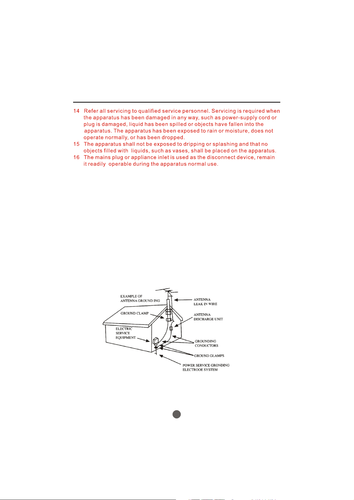
20. OUTDOOR ANTENNA GROUNDING
If an outside antenna or cable system is connected to the unit, be sure the antenna or cable
system is grounded to provide some protection against voltage surges and built-up static
charges, Section 810 of the National Electrical Code (NEC), ANSI/NFPA 70, provides
information with respect to proper grounding of the mast and supporting structure,
grounding of the lead-in wire to an antenna discharge unit, size of grounding conductors,
location of antenna discharge unit, connection to grounding electrodes, and requirements
for the grounding electrode.
21. SERVICING
Do not attempt to service this unit yourself as opening or removing covers may expose you
to dangerous voltage or other hazards. Refer all servicing to qualified service personnel.
3

Important safety Instructions
22. DAMAGE REQUIRING SERVICE
Unplug this unit from the wall outlet and refer servicing to qualified service personnel under
the following conditions:
a. When the power-supply cord or plug is damaged.
b. If liquid has been spilled, or objects have fallen into the unit.
c. If the unit has been exposed to rain or water.
d. If the unit does not operate normally by following the operating instructions. Adjust
only those controls that are covered by the operating instructions, as an improper
adjustment of other controls may result in damage and will often require extensive
work by a qualified technician to restore the unit to its normal operation.
e. If the unit has been dropped or the cabinet has been damaged.
f. When the unit exhibits a distinct change in performance, this indicates a need for
service.
23. REPLACEMENT PARTS
When replacement parts are required, be sure the service technician uses replacement parts
specified by the manufacturer or those that have the same characteristics as the original part.
Unauthorized substitutions may result in fire, electric shock or other hazards.
24. SAFETY CHECK
Upon completion of any service or repairs to this unit, ask the service technician to perform
safety checks to determine that the unit is in proper operating condition.
25. HEAT
The product should be situated away from heat sources such as radiators, heat registers,
stoves, or other products (including amplifiers) that produce heat.
26. DISC SLOT
Keep your fingers well clear of the disc slot as it is closing. It may cause serious personal
injury.
27. CONNECTING
When you connect the product to other equipment, turn off the power and unplug all of the
equipment from the wall outlet. Failure to do so may cause an electric shock and serious
personal injury. Read the owner's manual of the other equipment carefully and follow the
instructions when making any connections.
28. SOUND VOLUME
Reduce the volume to the minimum level before you turn on the product. Otherwise, sudden
high volume sound may cause hearing or speaker damage.
29. SOUND DISTORTION
Do not allow the product output distorted sound for a longtime. It may cause speaker
overheating and fire.
30. LASER BEAM
Do not look into the opening of the disc slot or ventilation opening of the product to see the
source of the laser beam. It may cause sight damage.
31. DISC
Do not use a cracked, deformed, or repaired disc. These discs are easily broken and may
cause serious personal injury and product malfunction.
32. NOTE TO CABLE TV SYSTEM INSTALLER
This reminder is provided to call the Cable TV system installer's attention to Article 820-40 of
the NEC that provides guidelines for proper grounding and, in particular, specifies that the
cable ground shall be connected to the grounding system of the building, as close to the point
of cable entry as practical.
4
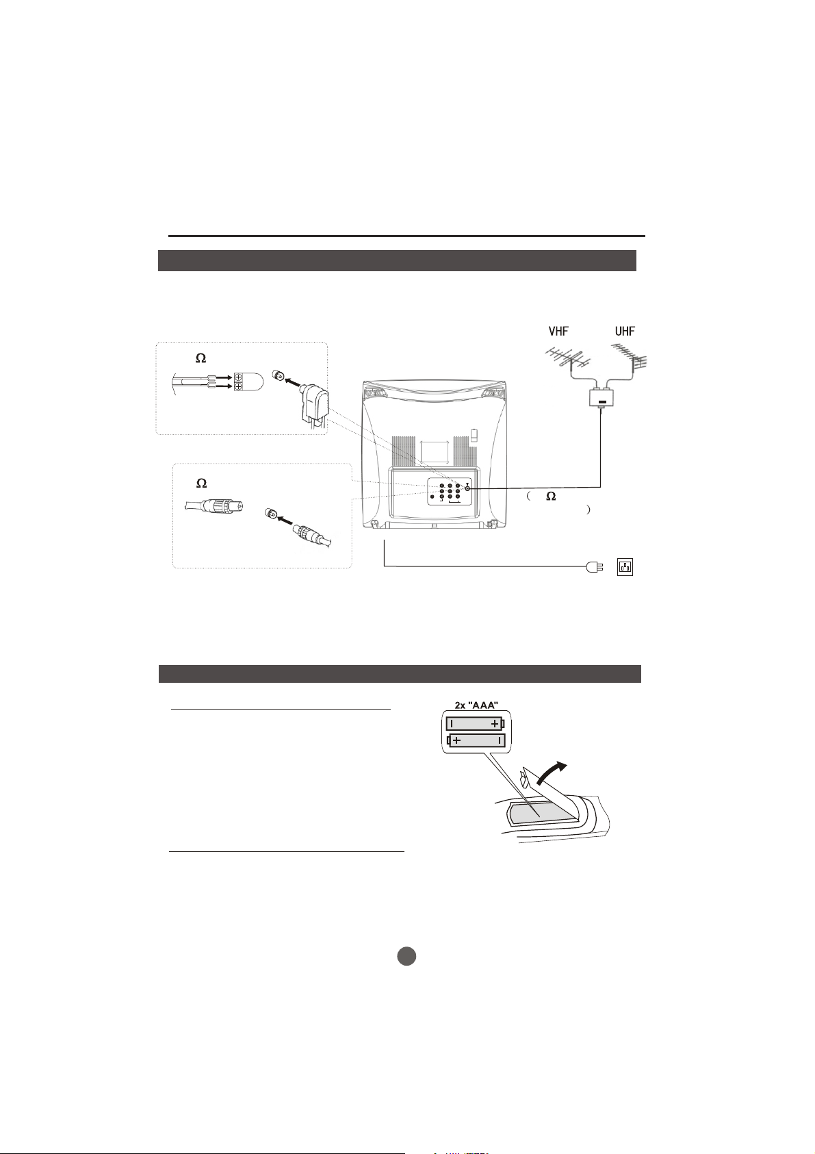
Installation
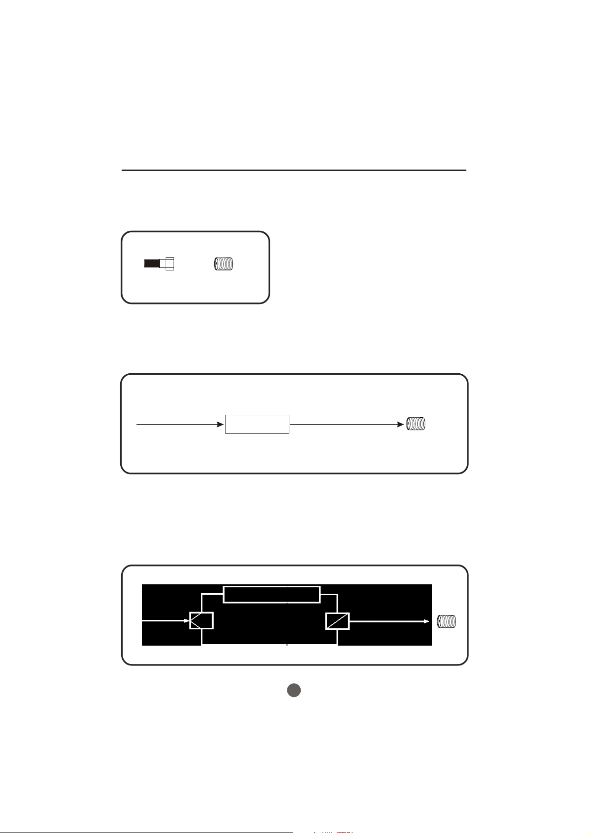
Antenna connection
If the picture is not clear or is snowy, it is recommended that an External Aerial
is used, this is usually mounted outside.
300 twin-lead cable
Antenna adapter
(Not supplied)
75 coaxial cable
OUT
VIDEO1
YCbCr
IN
LR
AUDIO1
Aerial input
75 standard
coaxial type
Plug
(Not supplied)
AC power socket
Note:
* It is recommended that a 75 ohm coaxial antenna is used to avoid
interference.
*To avoid interference from electrical signals, do not bind the antenna
cable together with any mains lead.
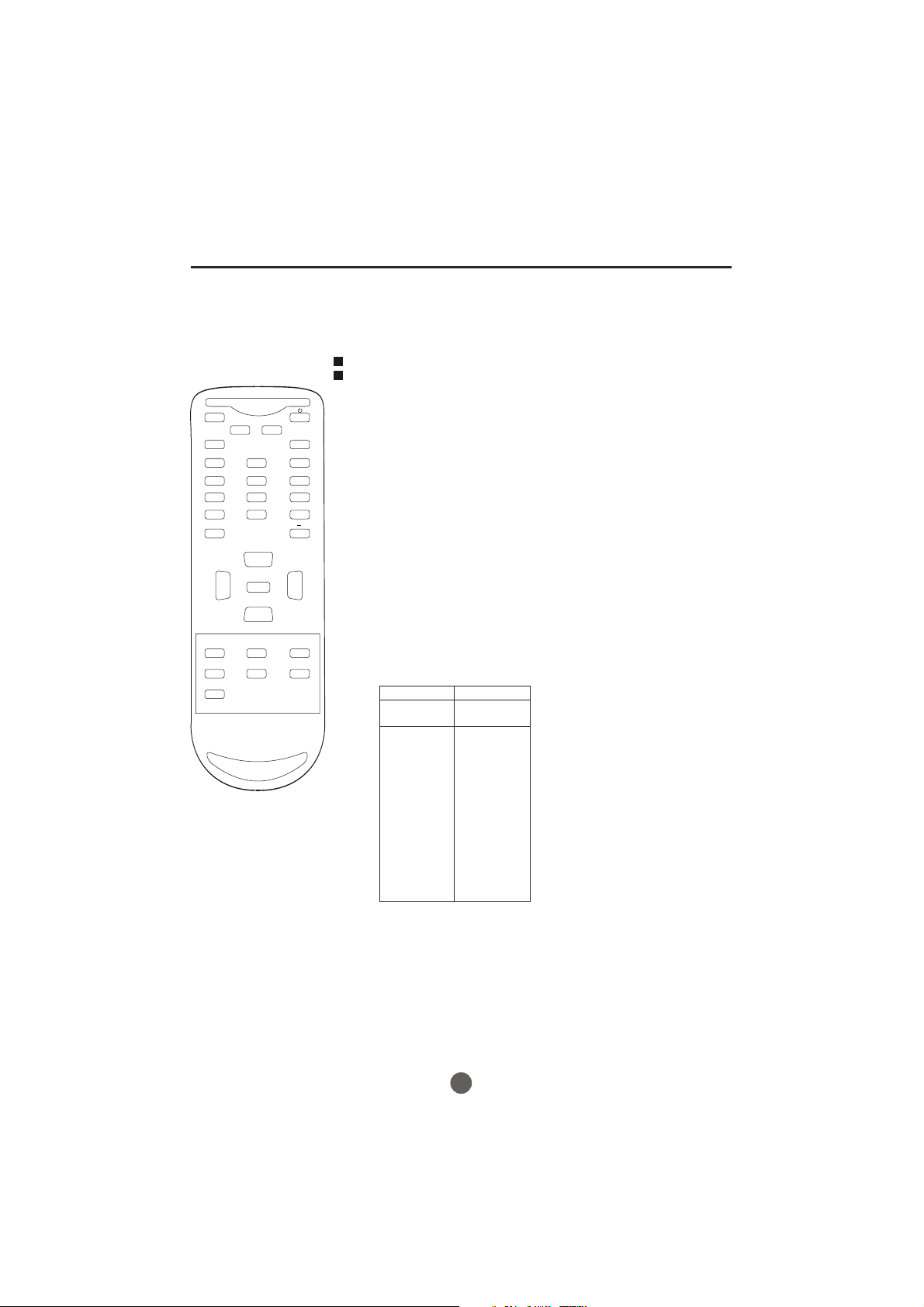
Preparation for the remote control
Battery installation
!
Remove the battery cover.
Insert two size AAA batteries matching
!
the +/-polarities of the battery to the +/marks inside the battery compartment.
Tips for remote operation
!When the remote control will not be used for a long period of time or when the
batteries are worn out, remove the batteries to prevent leakage.
!Do not throw the batteries into fire. Dispose of used batteries in the specified
manner.
!Do not drop, dampen or disassemble the remote control.
5
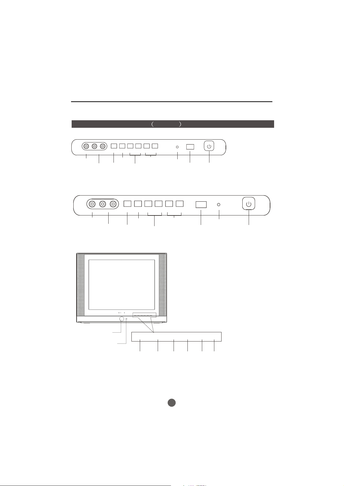
Front panel the TV set Video 2
HTR13-A
MENU
TV/AV
L-AUDIO-RVIDEO
VIDEO IN jack
AUDIO IN (L/R) jacks
TV/AV
switching
HTR20-A/HTF20-A
L-AUDIO-R
VIDEO
VOL- VOL+ CH- CH+
MENU
Volume
decrease/
increase
TV/AV
Channel
down/up
MENU
VOL- VOL+ CH- CH+
Indicator light
Parts and functions
Power Switch
Signal
Receiver
VIDEO IN jack
AUDIO IN (L/R) jacks
HTF201-A
Power Button
Power Indicator
and remote
receiving window
TV/AV
switching
MENU
Volume
decrease/
increase
TV/AV MENU
V+V- CH- CH+
TV/AV MENU
Input
source
display
Menu
Channel
down/up
Volume
down
V+V-
Volume
up
Signal
Receiver
CH-
Channel
down
Indicator light
CH+
Channel
up
Power Switch
6
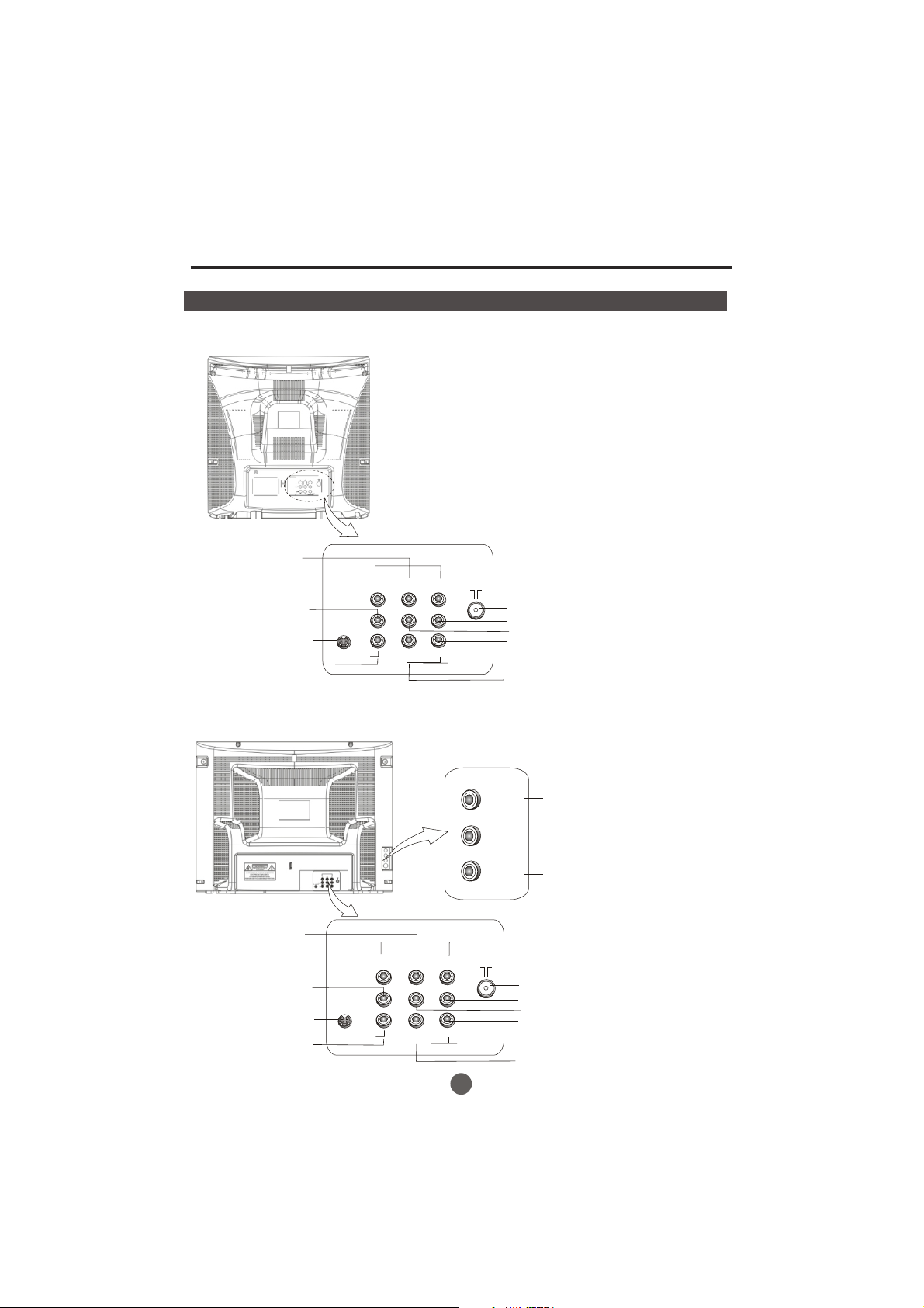
Parts and functions
Rear panel of the TV set
HTR13-A/HTR20-A/HTF20-A
Component video
input terminal
YCbCr
Video output terminal
S-VIDEO input terminal
Video input terminal
*S-VIDEO is only available in some models.
HTF201-A
OUT
VIDEO1
IN
L R
AUDIO1
Antenna input socket
Audio right channel output terminal
Audio left channel output terminal
Audio right channel input terminal
Audio left channel input terminal
Component video
input terminal
Video output terminal
S-VIDEO input terminal
Video input terminal
YCbCr
OUT
IN
VIDEO1
L R
AUDIO1
7
VIDEO
L
AUDIO
R
Video input terminal
Audio left channel output terminal
Audio right channel output terminal
Antenna input socket
Audio right channel output terminal
Audio left channel output terminal
Audio right channel input terminal
Audio left channel input terminal
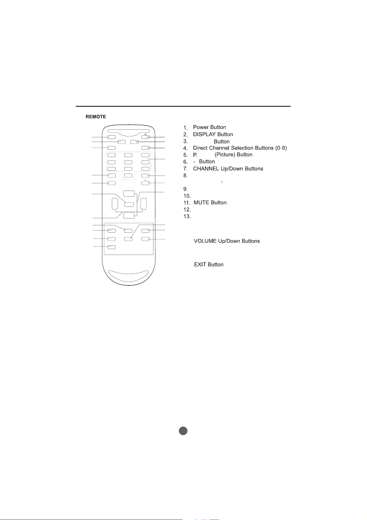
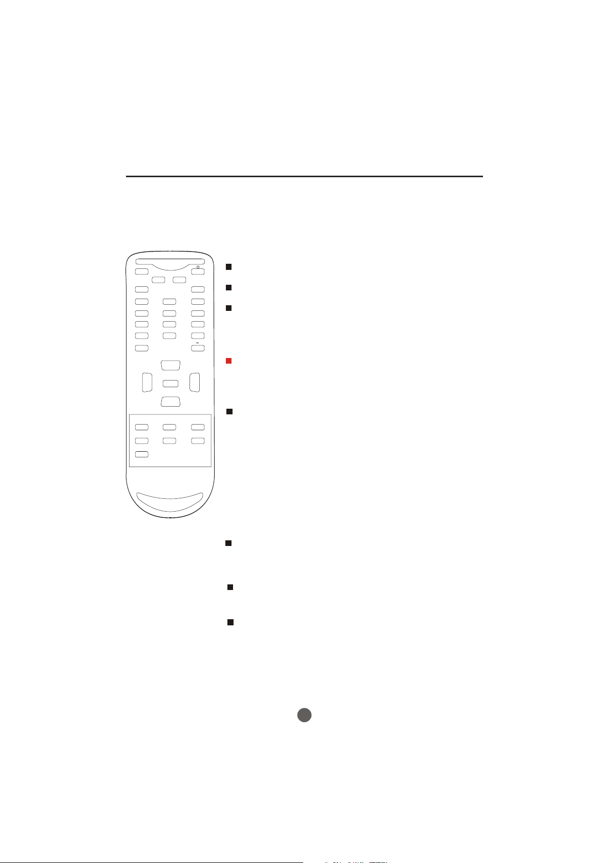
Remote control
11
12
13
14
15
16
17
18
19
20
21
MUTE
Q.VIEW INFO
INPUT TV/DTV
123
456
789
SAP P.MODE
0
OK
VOL
MENU
-
CC SLEEP FAV.LIST
ARC
GUIDE
EXIT
-
CH+
VOL
+
CH-
CH.LIST
1
2
3
4
5
6
7
8
9
10
TV/DTV
( The function is not available)
MODE
ARC( Button
Aspect Ratio Control)
(only in 16 9mode)
FAV.LIST Button
CH.LIST Button
Q.VIEW Button
INPUT Button
SAP Button
14.
15.
OK Button
16.
MENU Button
17.
18.
SLEEP Button
19.
CC(Closed Caption) Button
20.
GUIDE Button
21.
8
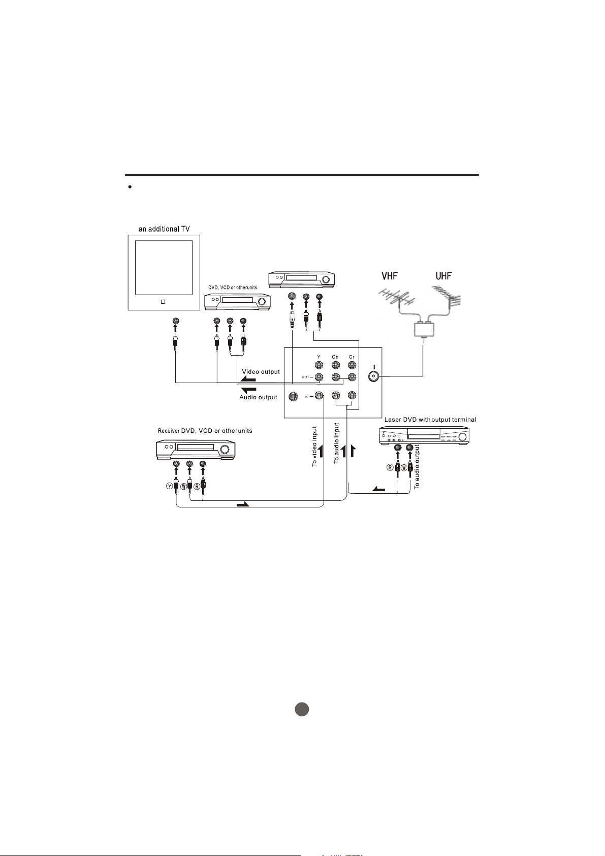
The other video and audio equipment Connections
You can connect the DVD,VCR and stereo system to the output to enjoy a
higher quality of picture and sound effect.
With S-Video
S-Video
VIDEO1 L- RAUDIO1-
ANT IN
9
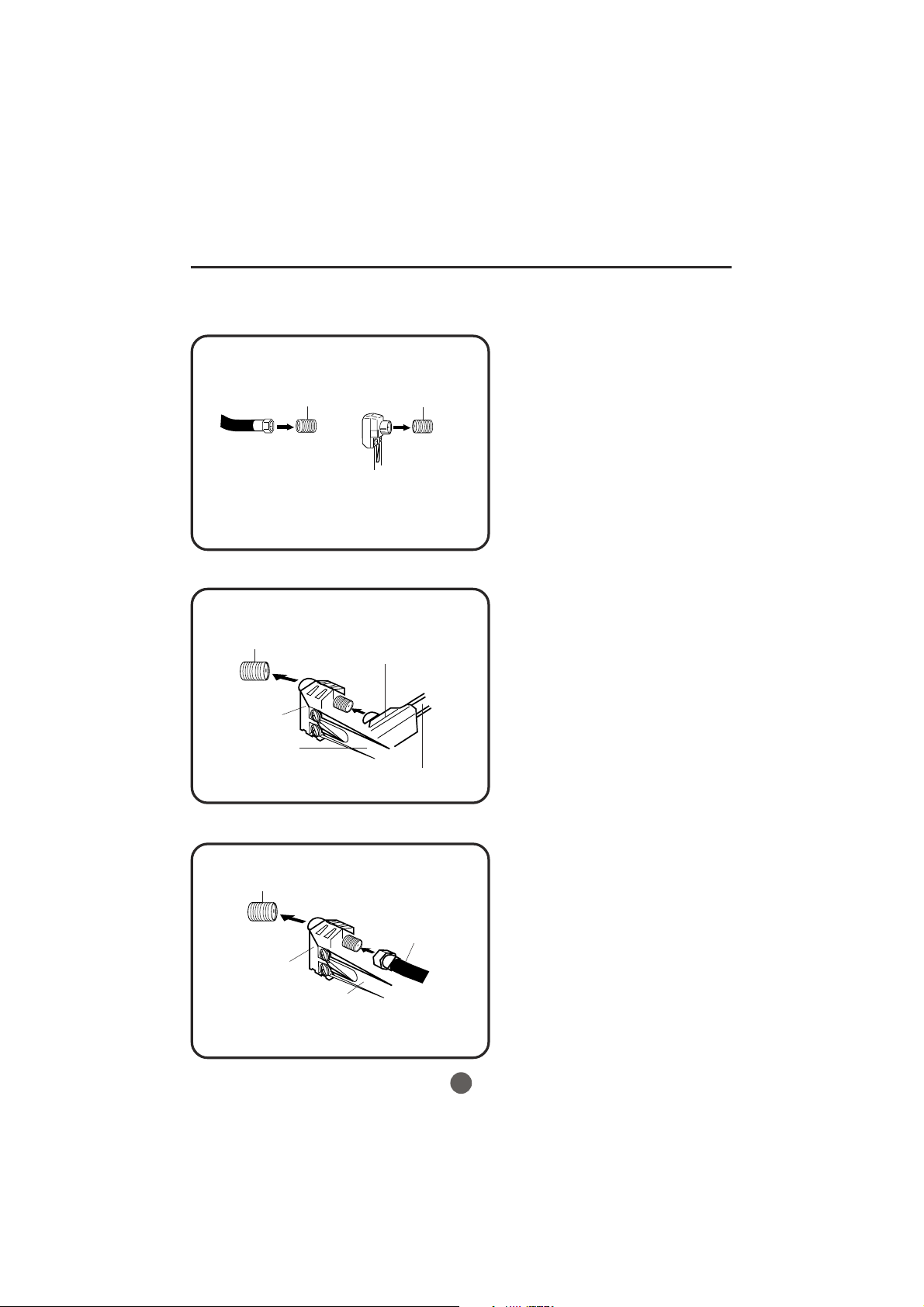
Antenna connections
If you are using an indoor or outdoor antenna, follow the instructions below that correspond to your antenna
system. If you are using a cable TV service (CABLE), see the Cable TV connections.
Combination VHF/UHF antenna (Single 75 ohm cable or 300 ohm twin-lead wire)
Connect the 75 ohm cable from the combination
VHF/UHF antenna to the RF IN jack.
RF IN
jack
75 ohm
coaxial
cable
300-75 ohm
matching
transformer
Combination VHF/UHF antenna (Separate VHF and UHF 300 ohm twin-lead wires)
RF IN
jack
300-75 ohm
matching
transformer
RF IN
jack
If using a flat UHF 300 ohm twin-lead wire,
connect these flat wires to an optional 75/300
ohm matching transformer/adapter (available
at many retailers), and then connect the
adapter to the 'RF' IN connector on the back
of the television.
Connect the UHF 300 ohm twin-lead wire to the
combiner (not supplied). Connect the VHF 300
ohm twin-lead wire to the 300-75 ohm matching
transformer.Attach thetransformer to the combiner,
then attach the combiner to the RF IN jack.
Combiner
UHF 300 ohm
VHF 300 ohm
Separate VHF/UHF antennas (75 ohm VHF cable and 300 ohm UHF twin-lead wires)
RF IN
jack
Combiner
VHF 75 ohm
UHF 300 ohm
Connect the VHF 75 ohm cable and UHF 300 ohm
twin-lead wire to the combiner. Attach the combiner
to the RF IN jack.
10
Cable TV connections
This unit has an extended tuning range and can tune most cable channels without using a Cable TV
Converter box. Some cable companies offer "premium pay channels" in which the signal is
scrambled. Descrambling these signals for normal viewing requires the use of a descrambler device
which is generally provided by the cable company.
FOR SUBSCRIBERS TO BASIC CABLE TV SERVICE
For basic cable service not requiring a Converter/Descrambler
box, connect the 75 ohm Coaxial Cable directly to the RF IN
Jack on the back of the unit.
75 ohm
coaxial cable
RF IN
jack
FOR SUBSCRIBERS TO SCRAMBLED CABLE TV SERVICE
If you subscribe to a cable TV service which requires the use of a converter/descrambler box, connect the
incoming 75 ohm coaxial cable to the converter/descrambler box. Using another 75 ohm coaxial cable, connect
the output jack of the converter/descrambler box to the RF IN jack on the unit. Follow the connections shown
below. Set the unit to the output channel of the converter/descrambler box (usually channel 3 or 4) and use the
converter/descrambler box to select channels.
Incoming
75 ohm
cable TV cable
Converter/
descrambler
75 ohm cable to
unit
RF IN
jack
FOR SUBSCRIBERS TO UNSCRAMBLED BASIC CABLE TV SERVICE WITH
SCRAMBLED PREMIUM CHANNELS
If you subscribe to a cable TV service in which basic channels are unscrambled and premium channels require the
use of a converter/descrambler box, you may wish to use a signal splitter and an A/B switch box (available from the
cable company or an electronics supply store). Follow the connections shown below. With the switch in the "B"
position, you can directly tune any nonscrambled channels on your unit. With the switch in the "A" position, tune your
unit to the output of the converter/descrambler box (usually channel 3 or 4) and use the converter/descrambler box
to tune scrambled channels.
Incoming
75 ohm
cable TV cable
Splitter
Converter/
descrambler
A/B switch
11
75 ohm cable
A
to unit
B
RF IN
jack
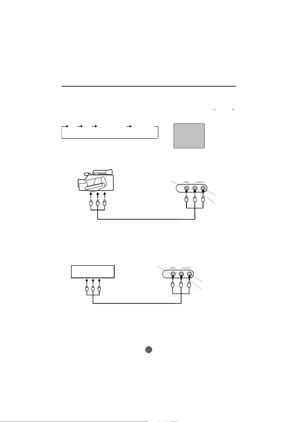
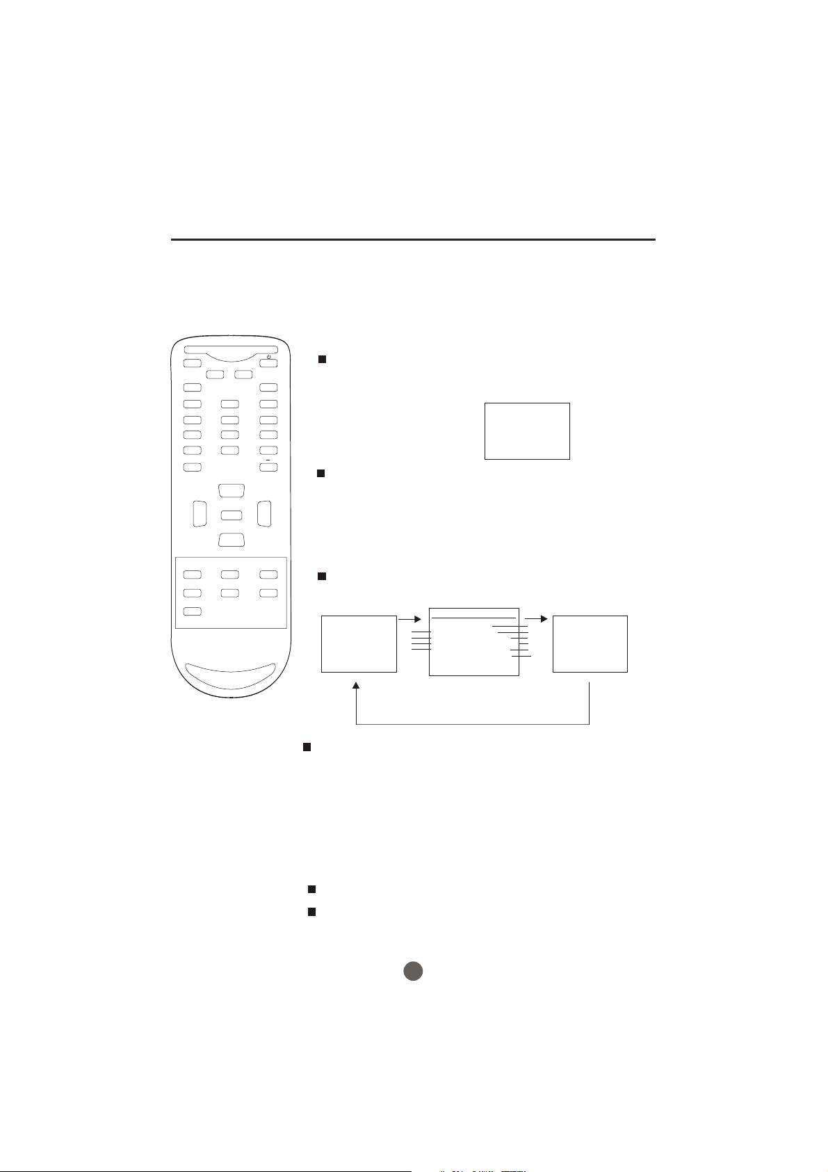
Connections to other equipment
Using the audio/video inputs
If you connect the TV to a camcorder or Video Game, you can select different modes by pressing
Press TV/AV repeatedly to select the desired mode.
"AV1", "AV2", "COMPONENT" or TV channel will display on the screen for seconds, no signal
will be displayed on the screen when no signal input.
TV/AV.
AV1 AV2 COMPONENT TV Channel
AV 1
To connect the TV to a camcorder
To playback from the camcorder, connect the camcorder to the unit as shown.
Camcorder
VIDEO IN
To Audio/Video OUT
Audio/Video cord (not supplied)
Front of TV
AUDIO IN (R)
AUDIO IN (L)
To connect the TV to a Video Game
The TV can also be used as a display device for many video games. However, due to the wide variety
of formats, they have not all been included in the suggested connection diagram. Youl need to consult
each component's Owner's Manual for additional information.
VIDEO IN
Front of TV
Video Game
To Audio/Video OUT
Audio/Video cord (not supplied)
AUDIO IN (R)
AUDIO IN (L)
12

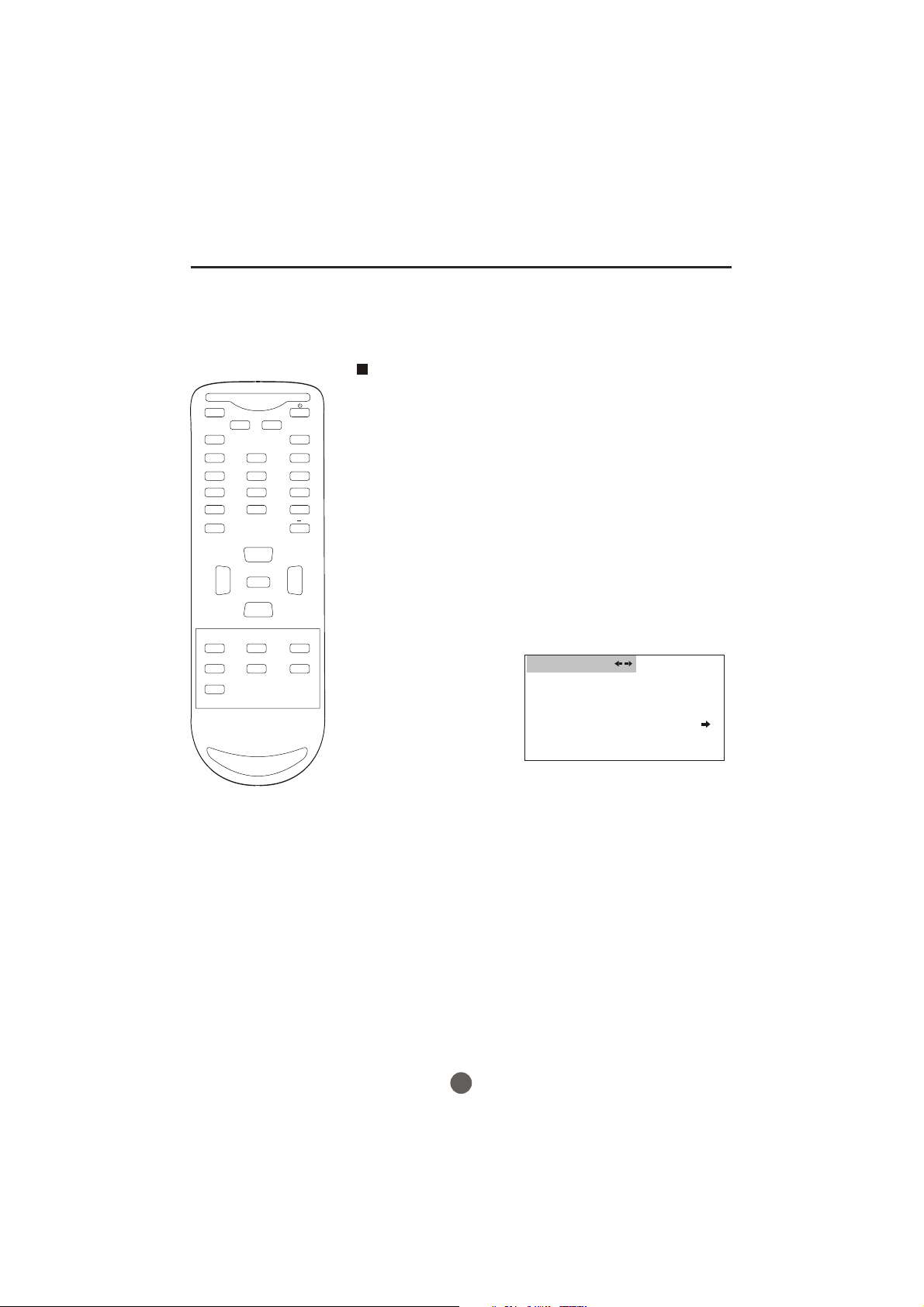
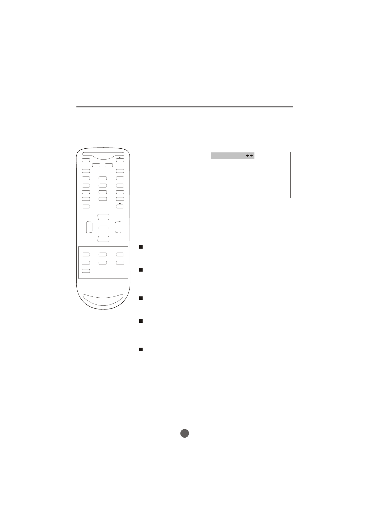
Setting the language and blue screen
Y
ou can choose from three different
languages (English, French and
Spanish) for the on-screen displays.
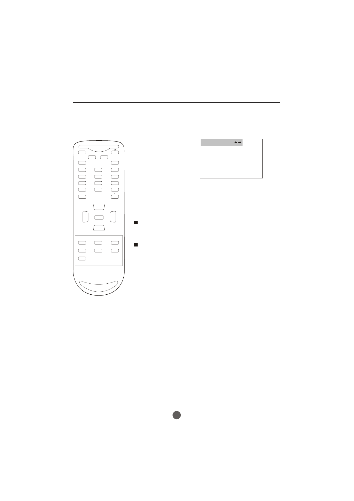
SETTING THE LANGUAGE
1 Press POWER ( ) to turn on the TV.
2 Press MENU, and then press VOL+/- button to
select FUNCTION menu, then press CH- button to
MUTE
Q.VIEW INFO
INPUT TV/DTV
123
456
789
SAP P.MODE
0
OK
-
enter.
FUNCTION
LANGUAGE ENGLISH
BLUE SCREEN ON
NTSC CAPTION C C1
DTV CAPTION
PARENTAL LOCK
CH+
VOL
-
CC SLEEP FAV.LIST
GUIDE
EXIT
MENU
ARC
VOL
CH-
CH.LIST
3 Press CH- button to select the LANGUAGE option,
+
then press VOL+/- to select the desired language:
English, Spanish or French.
4 Press MENU until the MENU screen disappears.
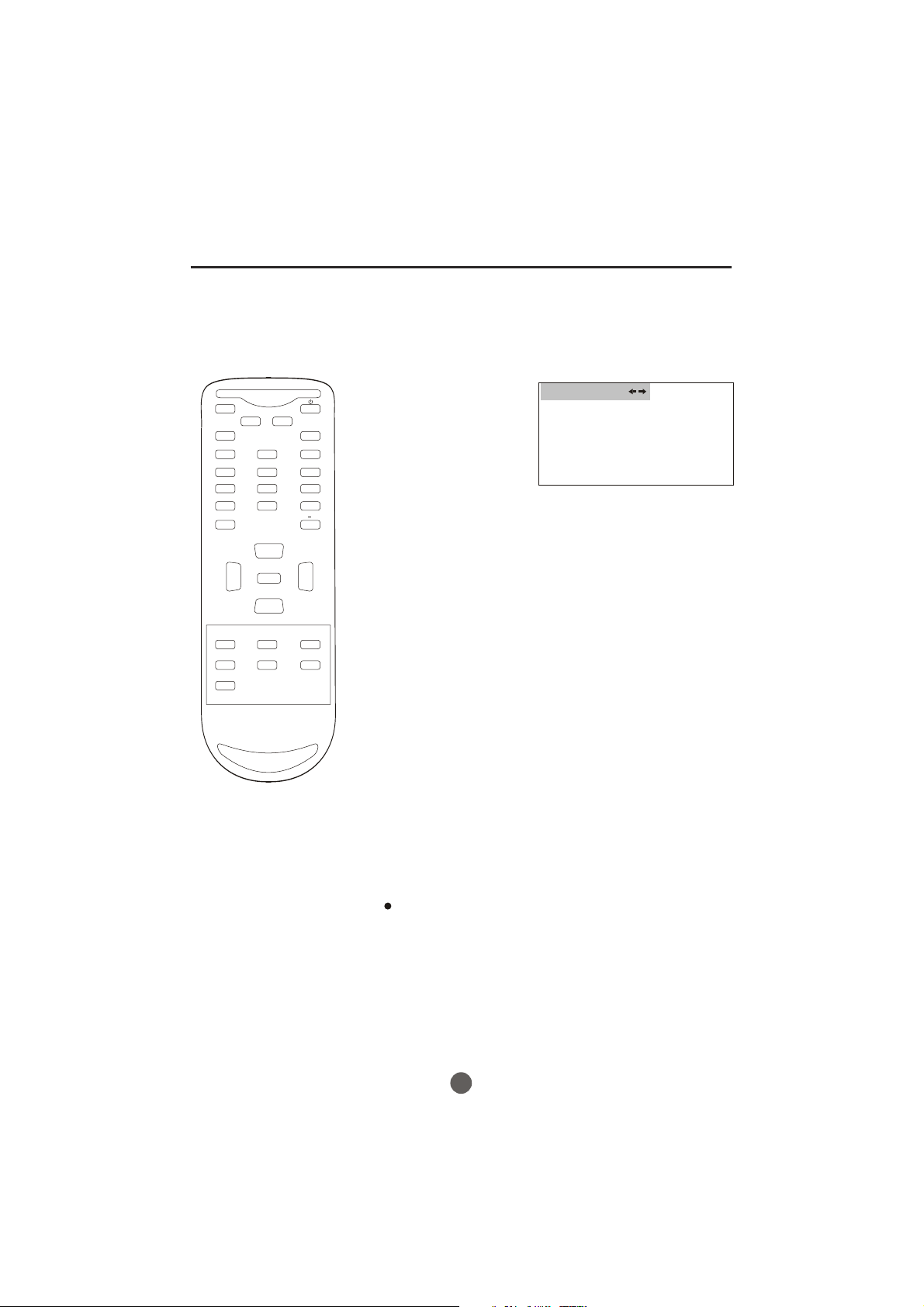
SETTING THE BLUE SCREEN
1 Press MENU, and then press VOL+/- button to
select FUNCTION menu, then press CH- button to
enter.
FUNCTION
LANGUAGE ENGLISH
BLUE SCREEN ON
NTSC CAPTION C C1
DTV CAPTION
PARENTAL LOCK
2 Press CH+/- button to select the BLUE SCREEN option,
then press VOL+/- to select OFF or ON.
3 Press MENU until the MENU screen disappears.
13
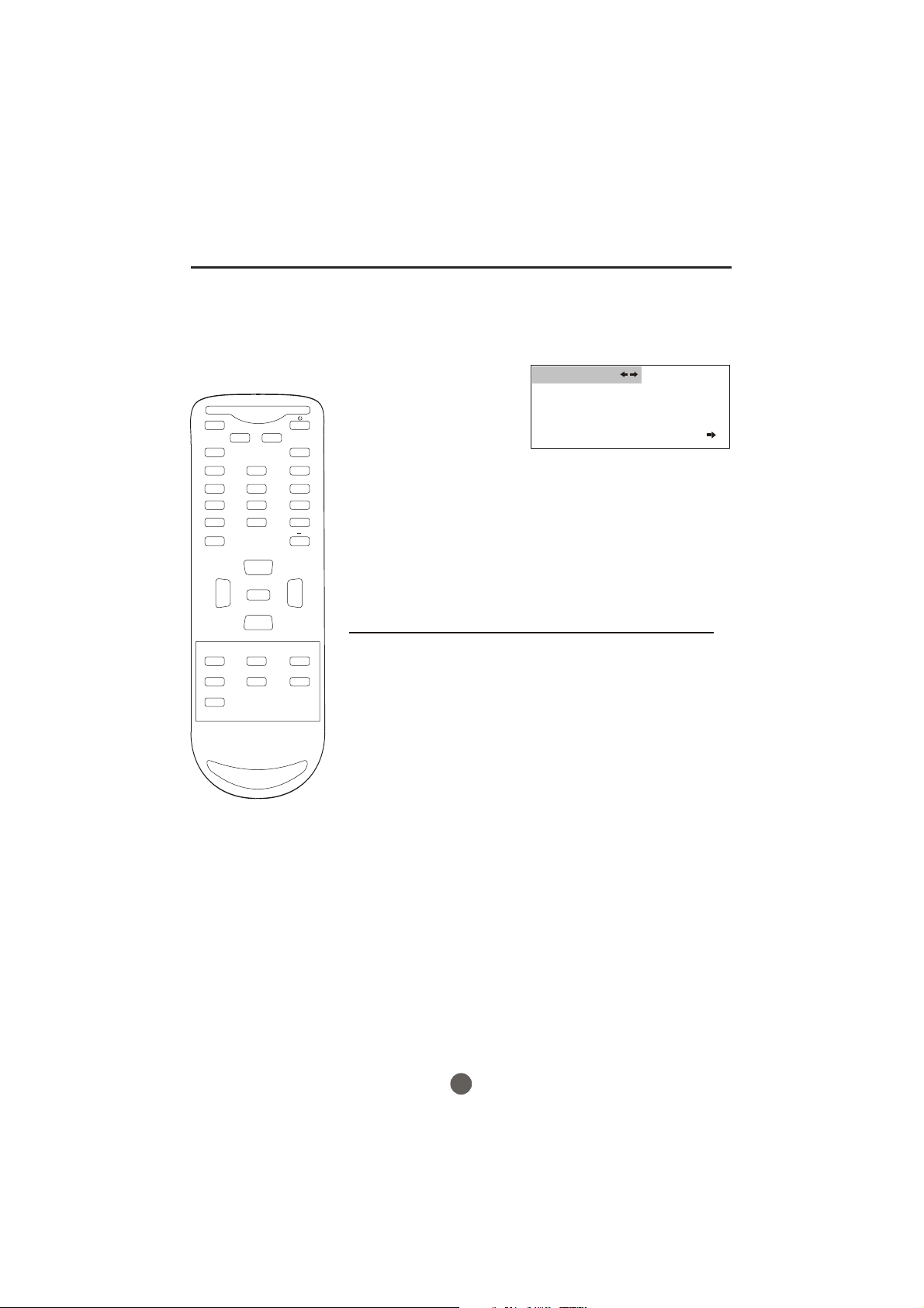
Channel menu
Here describes the case for searching and memorizing channels for DTV/ATV.
AUTO SCAN
MUTE
Q.VIEW INFO
INPUT TV/DTV
123
456
789
SAP P.MODE
GUIDE
EXIT
0
OK
VOL
MENU
-
CC SLEEP FAV.LIST
ARC
-
CH+
VOL
+
CH-
CH.LIST
The channels broadcasted are
automatically scanned and memorized. Only the
receivable channels in the area where this TV is
used will be memorized.
NOTE:
Be sure that antenna or cable is connected properly before plugging the
power cord.
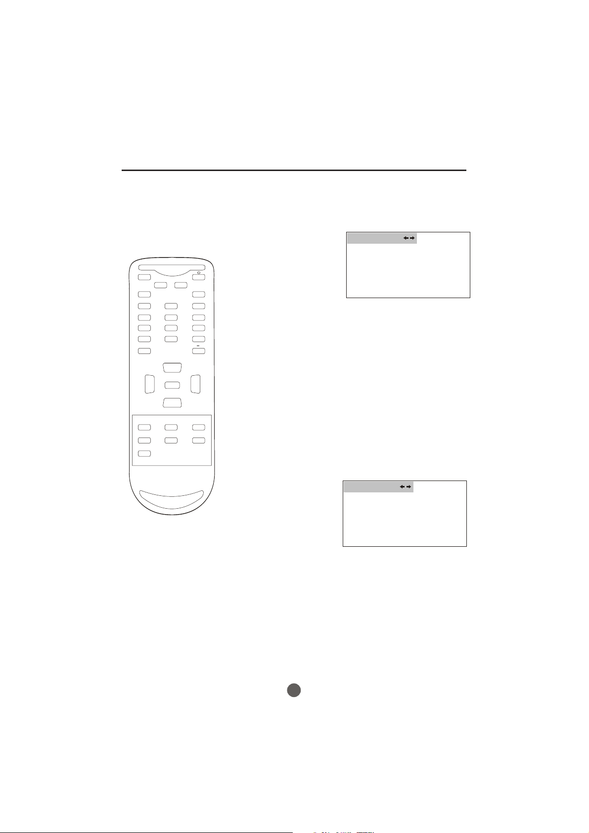
1 Press MENU, and then press VOL+/- button to select
CHANNEL menu, then press CH- button to enter.
CHANNEL
CHANNEL NO . 2.1
TUNER ANTENNA
SKIP OFF
AUTO SCAN
2 Press CH +/- button
to select AUTO SCAN option.
3 Press VOL+ button to start scanning.
When you pressVOL+ on the remote control,
scanning the channels in both analog and digital
modes will automatically start.
When scanning is completed, the memorized
smallest channel will be displayed.
When you pressMENU button while scanning, the
scanning is interrupted and the memorized smallest
channel is displayed.
14
Channel menu
MUTE
Q.VIEW INFO
INPUT TV/DTV
123
456
789
SAP P.MODE
0
OK
VOL
MENU
-
-
CH+
VOL
+
CH-
SETTING SKIP
After the programs are presetting, you can skip some
programs so that to select your favorite channels only.
1 Press MENU, and then
press VOL+/- button to
select CHANNEL menu,
then press CH- button to
enter.
CHANNEL
CHANNEL NO . 2.1
TUNER ANTENNA
SKIP OFF
AUTO SCAN
2 Press CH+/- button to
select the SKIP option,
then press VOL+/- button
to select ON or OFF.
NOTE: When tuning DTV channels and no signal is present,
the SKIP-ON option will be available.
If you want to recover the skipped channel
CC SLEEP FAV.LIST
CH.LIST
ARC
GUIDE
EXIT
1. Use Direct-digit Choosing button to select the number
of the channel to be recovered.
2. Do the above steps again.
3. Press VOL+/- button to set SKIP as Off.
15
MUTE
Q.VIEW INFO
INPUT TV/DTV
123
456
789
SAP P.MODE
0
OK
-
Channel selection
You can select the channel by using either CH +/- button
or Channel number buttons. How to select the channel
in each way is shown below.
1 Using CH +/- button
Using CH +/- button on the remote control, change the channel.
Same operation is available with CH +/- button on the front panel
of the main unit.
Press the Direct Channel selection
2
Antenna Mode Direct Channel Selection
When the Antenna/Cable menu option is in the Antenna position, all channels
can be instantly selected by using
2-9: Press 2-9 as needed.
Example, to select channel 2, press "2".
10-69: Press the 2 digits in order. If you select the channel more than 69,
the channel will not be change, it is no available.
buttons to select the channel.
digits button. For example:
CH+
VOL
-
CC SLEEP FAV.LIST
GUIDE
EXIT
MENU
CH-
ARC
VOL
CH.LIST
CABLE Mode Direct Channel Selection
When the Antenna/Cable menu option is in the Cable position, channels
+
can be selected as follows:
1-9: Press 1-9 as needed. Example, to select channel 2,
press "2".
10-99: Press the 2 digits in order. Example, to select channel 32,
press "3" then "2".
100-125: Press the digital 1 button, the "1--" will appear
on the screen, then press the 2 digits of remain in order.
TV
VHF
2-13
UHF
14-69
CABLE
VHF
2-13
STD/HRC/IRC
14-36
(A) (W)
37-59
(AA) (WW)
60-85
(AAA) (ZZZ)
86-94
(86) (94)
95-99
(A-5) (A-1)
100-125
(100) (125)
01
(5A)
NOTE:
In the DTV broadcasting, one channel sometimes broadcasts
multiple programs depending on the air time. In this case, the
main channel is called major channel and the sub channel is
called minor channel.
16
Volume adjustment
This section describes how to adjust the volume when
viewing TV. The MUTE function, which is useful when
you have a visitor or a phone call, will be also described.
MUTE
Q.VIEW INFO
INPUT TV/DTV
123
456
789
SAP P.MODE
GUIDE
EXIT
0
OK
VOL
MENU
-
CC SLEEP FAV.LIST
ARC
-
CH+
VOL
+
CH-
CH.LIST
1 Using VOL +/-button
You can adjust the audio volume with VOL +/- button on
the remote control.
The volume bar is displayed at the bottom of the screen
when adjusting the volume.
Same operation is available with VOL +/- on the front
panel of the main unit.
2 Using MUTE button
Press MUTE button on the remote control to mute the
sound.
The MUTE button is displayed on the screen while
muting.
To release the MUTE status, press MUTE button again
or press VOL+ button.
MUTE will displayed continuously When CC is OFF, MUTE
will disappeared 5 seconds later When CC is ON.
SWITCHING AUDIO
This section describes how to switch the audio language
in the digital mode.
Switch the audio language.
When you pressSAP button on the remote control, the
currently selected language and the number of received
languages will be displayed on the screen.
Every time you press SAP button on the remote control,
the language will be switched.
Languages you can switch differ depending on the
receiving broadcast.
NOTE:
Pressing the SAP button works only with the some TV
channels, and does not work with external equipment such as
DVD players.
17
MUTE
Q.VIEW INFO
INPUT TV/DTV
123
456
789
SAP P.MODE
0
OK
VOL
MENU
-
-
CH+
VOL
+
CH-
Screen information
You can display the currently selected channel number or
other information such as the audio mode on the screen
for checking.
In the analog mode, the currently selected channel
number and the audio mode are displayed.
1 Display the channel number and the audio mode.
Press INFO button on the remote control.
The currently selected channel number and the audio
mode are displayed at the top right of the screen.
13
ATV-AIR
MONO
To clear the display, press INFO button again.
In the digital mode, the detailed information for the
currently selected channel such as the program
GUIDEe is displayed.
CC SLEEP FAV.LIST
CH.LIST
ARC
GUIDE
EXIT
Display the detailed information for the channel.
Every time you press INFO button, the display mode
will be switched as below.
14.1
DTV-AIR
INFORMATION
1
MBC DTV [1920*1080]
2
NO PROGRAM INFO 16:9
3
NO CC INFORMATION UNKNOWN
4
NO RATING 07:19-09:56
NO PROGRAM INFORMATION
IS AVAILABLE
11-1
5
6
7
8
9
10
The following information is displayed in the INFO mode.
(1) Channel title (6) Resolution
Program content
(2) (7) Zoom
(3) Closed caption (8) Audio language
(4) Channel title (9) Program air time
(5) Channel number (10) Program content
NOTES:
When the program guide is displayed in more than 6 lines, use VOL+/-
button and scroll for reading.
"No description provided" is displayed when the program guide is not
provided.
18
Video menu
MUTE
Q.VIEW INFO
INPUT TV/DTV
123
456
789
SAP P.MODE
GUIDE
EXIT
0
OK
VOL
MENU
-
CC SLEEP FAV.LIST
ARC
-
CH+
VOL
+
CH-
CH.LIST
SETTING VIDEO
1 Press MENU button. The main menu screen will appear.
2 Press VOL+/- button to
select VIDEO Option,
then press CH- button
to enter.
VIDEO
CONTRAST 80
BRIGHTNESS 80
SHARPNESS 50
COLOR 50
TINT +00
3 Press CH+/- to select the desired option, then press
VOL+/- to adjust.
Contrast
This will adjust the intensity of bright parts in the picture but keep
the dark parts unchanged.
Brightness
This will adjust the light output of the complete picture, which will
mainly affect the darker areas of the picture.
Sharpness
This will adjust the sharpness of fine details in the picture.
Color
This will adjust the saturation level of the colors to suit your
personal preference.
Tint
Allows you to select the color mix (Tint) of the picture.
19
Audio menu
SETTING AUDIO
Press MENU button. The main menu screen will appear.
1
MUTE
Q.VIEW INFO
INPUT TV/DTV
123
456
789
SAP P.MODE
GUIDE
EXIT
0
OK
VOL
MENU
-
CC SLEEP FAV.LIST
ARC
-
CH+
VOL
+
CH-
CH.LIST
2 Press VOL+/- button to
select AUDIO Option,
then press CH- button
to enter.
AUDIO
VOLUME 80
BALANCE +00
3 Press CH+/- to select
the desired option, then
press VOL+/- to adjust.
Volume
This will adjust the sound output level.
Balance
This will adjust the sound output balance.
20
Manual time setting
You must set the time manually
for ON/OFF Timer.
MUTE
Q.VIEW INFO
INPUT TV/DTV
123
456
789
SAP P.MODE
0
OK
VOL
MENU
-
CC SLEEP FAV.LIST
ARC
GUIDE
EXIT
-
CH+
VOL
+
CH-
CH.LIST
EXAMPLE: Setting the time to "8:30 AM"
TO SET TIME
1 Press MENU. The main menu screen will appear.
2 Press VOL+/- button to
select TIME option,
then press CH- button
to enter the submenu.
TIME
TIME --:-- A M
TIMER ON --:-- A M
TIMER OFF --:-- AM
DAYLIGHT SAVING ON
TIME ZONE CENTRAL
3 Press CH+/- button to
select TIME, then press
CH+/- button to select
"--:--","AM";
press VOL+/- button to
set the value & AM &PM.
4 Press MENU until the MENU screen disappears.
NOTE:
After a power failure or disconnection of the power, the
time will get lost. In this case, reset the preset time.
21
Setting the ON/OFF timer
This feature allows you to have the
TV automatically turn on/off at a
predetermined
time. If you program
The ON/OFF TIMER, the TV will turn
on/off at the time your predetermined.
MUTE
Q.VIEW INFO
INPUT TV/DTV
123
456
789
SAP P.MODE
GUIDE
EXIT
0
OK
VOL
MENU
-
CC SLEEP FAV.LIST
ARC
-
CH+
VOL
+
CH-
CH.LIST
SETTING THE TIMER ON
1
Press MENU. The main menu screen will appear.
2 Press VOL+/- button to
select TIME option,
then press CH- button
to enter the submenu.
3 Press CH+/- button to
select TIME ON, then
press CH+/- button to
select "--:--","AM";
press VOL+/- button to
set the value.
TIME
TIME --:-- A M
TIMER ON --:-- A M
TIMER OFF --:-- AM
DAYLIGHT SAVING ON
TIME ZONE CENTRAL
4 Press MENU until the MENU screen disappears.
SETTING THE TIMER OFF
1 Press MENU. The main menu screen will appear.
2 Press VOL+/- button to
select TIME option,
then press CH- button
to enter the submenu.
3 Press CH+/- button to
select TIME OFF, then
press CH+/- button to
select "--:--","AM";
press VOL+/- button to
set the value.
TIME
TIME --:-- A M
TIMER ON --:-- A M
TIMER OFF --:-- AM
DAYLIGHT SAVING ON
TIME ZONE CENTRAL
4 Press MENU until the MENU screen disappears.
22
Function menu
MUTE
Q.VIEW INFO
INPUT TV/DTV
123
456
789
SAP P.MODE
0
OK
VOL
MENU
-
-
CH+
VOL
+
CH-
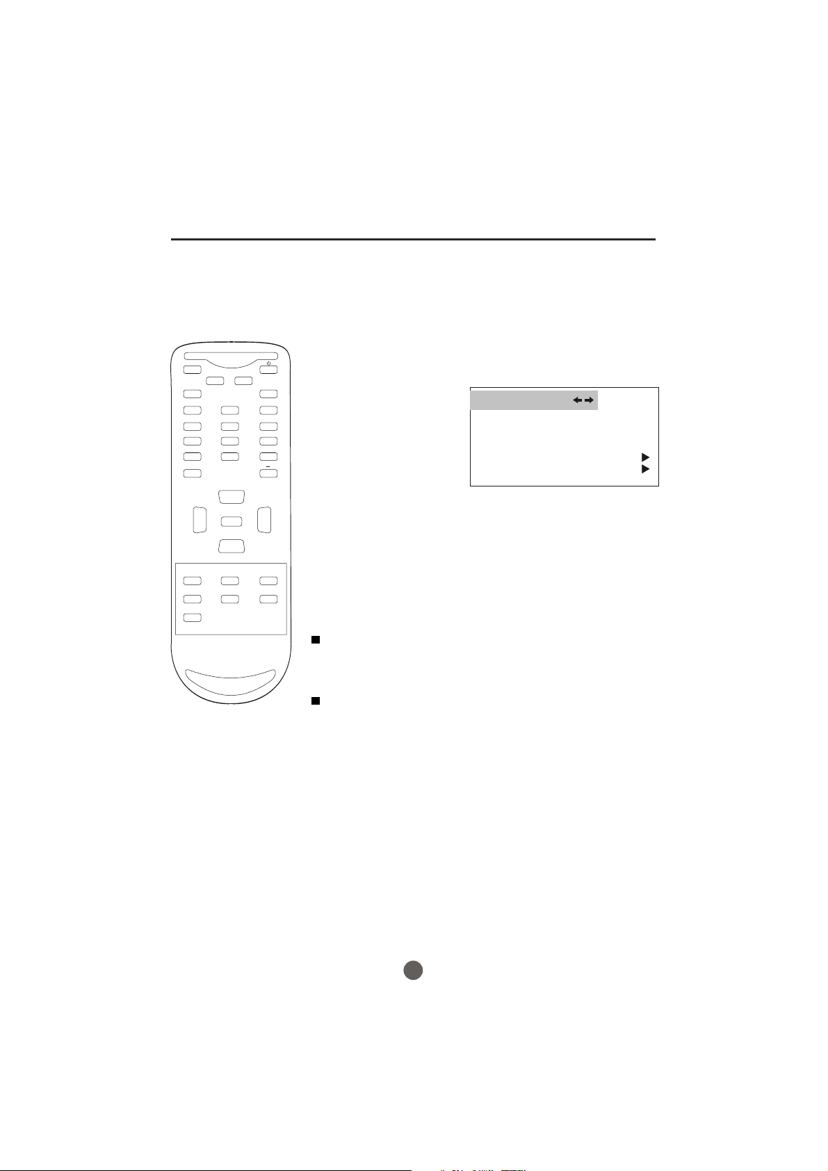
SETTING THE NTSC CAPTION
This allows you to configure the way you choose to view
the captioning.
1. Press the MENU button and then use VOL+/-button to select the
FUNCTION menu.
Press CH- button to enter,
2.
then p
to select NTSC CAPTION.
3.Then use VOL+/- button to
select caption:
CC2,CC3,CC4,TEXT1,
TEXT2,TEXT3, TEXT4 .
You can also press CC
button on the remote
control to select the
desired caption.
ress CH+/- button
OFF,CC1,
FUNCTION
LANGUAGE ENGLISH
BLUE SCREEN ON
NTSC CAPTION C C1
DTV CAPTION
PARENTAL LOCK
CC SLEEP FAV.LIST
CH.LIST
ARC
GUIDE
EXIT
4. When you are satisfied with
your choice, press MENU
button to return to the
previous menu.
CAPTION
The term for the words that scroll across the bottom of the TV
screen; usually the audio portion of the program provided for
the hearing impaired.
TEXT
The term for the words that appear in a large black frame and
almost cover the entire screen; usually messages provided by
the broadcaster.
23
 Loading...