

Page 1
Installation Manual of Room Air Conditioner
Read this manual before installation
Explain sufficiently the operating means to the user
according to this manual.
Necessary Tools for Installation
1.Driver
2.Hacksaw
3.Hole core drill
4.Spanner(17,19 and 26mm)
Accessory parts
No. Accessory parts
1
2
3
4
5
6
Remote controller
R-03 dry battery
Mounting plate
Drain hose
Steel nail, cement
4X25
Screw
Plastic cap
4X50
Number
of
articles
1
2
1
1
6
4
5.Torque wrench(17mm,22mm,26mm)
6.Pipe cutter
7.Flaring tool
8.Knife
9.Nipper 12.Reamer
10.Gas leakage detector or
soap-and-water solution
11.Measuring tape
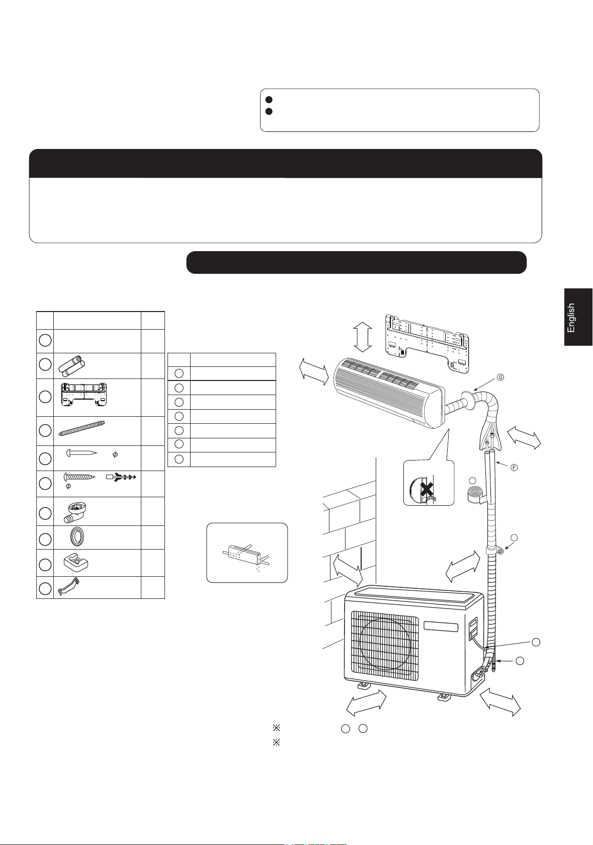
Drawing for the installation of indoor and outdoor units
Optional parts for piping
Mark
A
B
C
D
E
F
G
Parts name
Non-adhesive tape
Adhesive tape
Saddle(L.S) with screws
Connecting electric cable
for indoor and outdoor
Drain hose
Heating insulating material
Piping hole cover
more than 10cm
more than 5cm
Attention must be paid to
the rising up of drain hose
more than 10cm
A
7
8
9
10
Drain-elbow
Cover
Cushion
Pipe supporting plate
No.0010559435
1
1
4
Arrangement of piping directions
Rear left
Below
Rear
right
Right
Left
C
more than 10cm
more than 10cm
1
D
E
more than 60cm
A
The marks from to in the figure are the parts numbers.
G
The distance between the indoor unit and the floor should be
more than 2m.
more than 15cm
Page 2
140 415 140
2
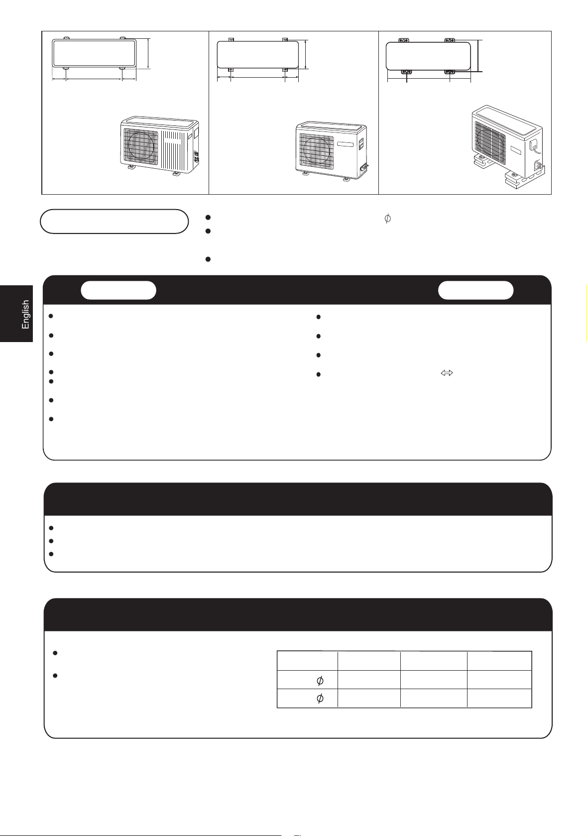
Floor fixing dimensions
of the outdoor unit
(Unit:mm)
HSU-09C12
HSU-12C12
HSU-09C13
HSU-12C13
HSU-09C03/Z1
HSU-12C03/Z1
082
140
500 140
Floor fixing dimensions
of the outdoor unit
(Unit:mm)
HSU-18C13
HSU-18CK03
652
113.5
583
Floor fixing dimensions
of the outdoor unit
(Unit:mm)
HSU-22C13
HSU-24C13
113.5
5
.
9
13
Fixing of outdoor unit
Fix the unit to concrete or block with bolts( 10mm) and nuts firmly and horizontally.
When fitting the unit to wall surface, roof or rooftop, fix a supporter surely with nails
or wires in consideration of earthquake and strong wind.
If vibration may affect the house, fix the unit by attaching a vibration-proof mat.
Indoor Unit
Place, robust not causing vibration, where the body can be supported
sufficiently.
Place, not affected by heat or steam generated in the vicinity, where
inlet and outlet of the unit are not disturbed.
Place, possible to drain easily, where piping can be connected with the
outdoor unit.
Place, where cold air can be spread in a room entirely.
Place, nearby a power receptacle, with enough space around. (Refer
to drawings).
Place where the distance of more than lm from televisions, radios,
wireless apparatuses and fluorescent lamps can be left.
In the case of fixing the remote controller on a wall, place where the
indoor unit can receive signals when the fluorescent lamps in the room
are lightened.
Selection of Installation Place
Power Source
Outdoor Unit
Place, which is less affected by rain or direct sunlight and is
sufficiently ventilated.
Place, possible to bear the unit, where vibration and noise are
not increased.
Place, where discharged wind and noise do not cause a
nuisance to the neighbors.
Place, where a distance marked is available as illustrated
in the above figure.
Before inserting power plug into receptacle, check the voltage without fail. The power source is the same as the corresponding name plate.
Install an exclusive branch circuit of the power.
A receptacle shall be set up in a distance where the power cable can be reached. Do not extend the cable by cutting it.
Selection of pipe
To this unit, both liquid and gas pipes shall be insulated
as they become Iow temperature in operation.
Use optional parts for piping set or pipes covered with
equivalent insulation material.
For 09
Gas pipe( )
Gas pipe( ) 9.52mm(3/8")
6.35mm(1/4")
For 12,18
6.35mm(1/4")
12.7mm(1/2")
For 22 24
9.52mm(3/8")
15.88mm(5/8")
Page 3
Indoor unit
3
Indoor unit
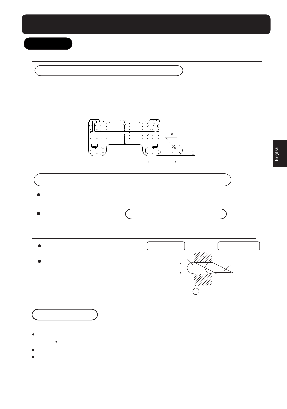
1.Fitting of the Mounting Plate and Positioning of the wall Hole
When the mounting plate is first fixed
1.Carry out, based on the neighboring pillars or lintels, a proper leveling for the plate to be
fixed against the wall, then temporarily fasten the plate with one steel nail.
2. Make sure once more the proper level of the plate, by hanging a thread with a weight from
the central top of the plate, then fasten securely the plate with the attachment steel nail.
3. Find the wall hole location A using a measuring tape
60mm
B=
A=145mm
30mm
When the mounting plate is fixed side bar and lintel
Fix to side bar and lintel a mounting bar, Which is separately sold, and then fasten
the plate to the fixed mounting bar.
Refer to the previous article, " When the mounting plate is first fixed ", for the
position of wall hole.
2.Making a Hole on the Wall and Fitting the Piping Hole Cover
Make a hole of 60 mm in diameter,
slightly descending to outside the wall.
Install piping hole cover and seal it
off with putty after installation
Indoor side
Wall hole
60mm
(Section of wall hole)
G
Piping hole pipe
Outdoor side
Thickness
of wall
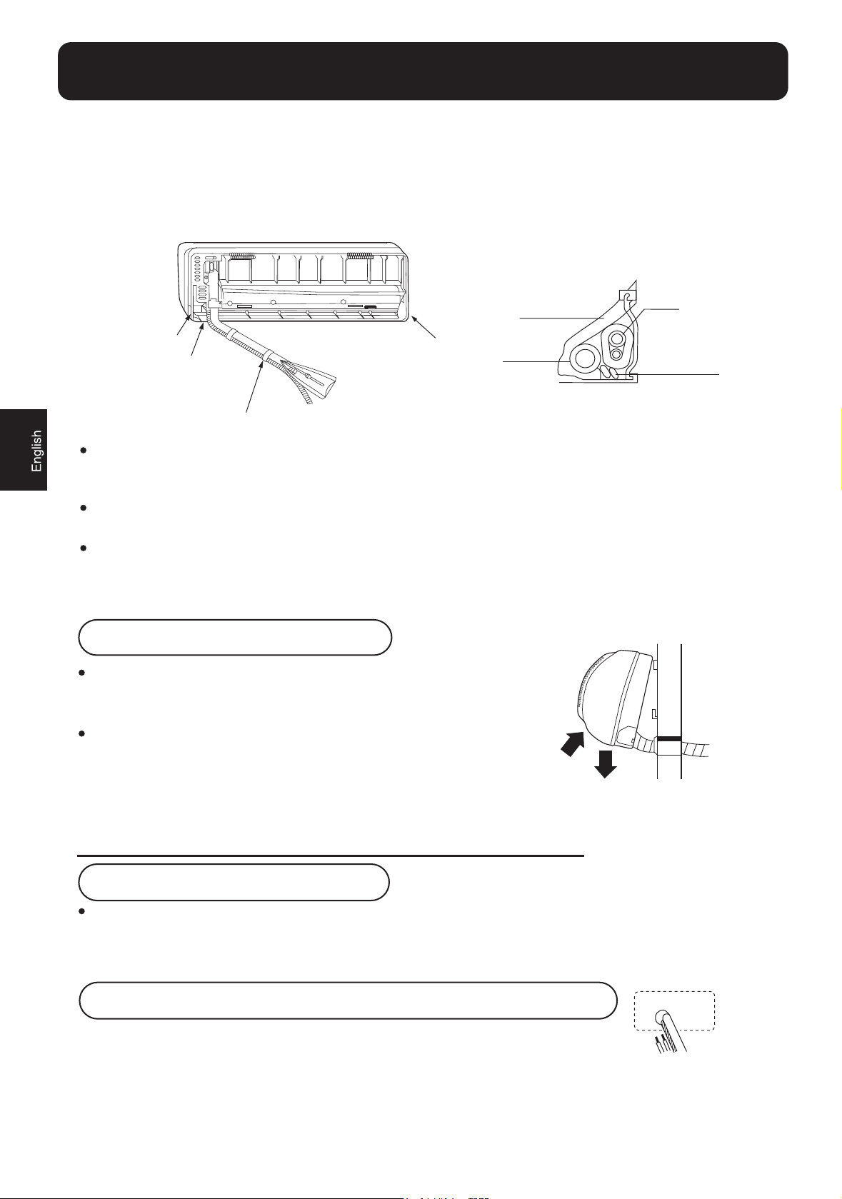
3.Installation of the Indoor Unit
Drawing of pipe
[ Rear piping ]
Draw pipes and the drain hose, then fasten them with the adhesive tape
[ Left Left-rear piping ]
In case of left side piping, cut away, with a nipper, the lid for left piping.
In case of left-rear piping, bend the pipes according to the piping direction to the mark of hole for left-rear
piping which is marked on heat insulation materials.
Page 4
Indoor unit
4
1. Insert the drain hose into the dent of heat insulation materials of indoor unit.
2. Insert the indoor/outdoor electric cable from backside of indoor unit, and pull it out on the front side, then
connect them.
3. Coat the flaring seal face with refrigerant oil and connect pipes.
Cover the connection part with heat insulation materials closely, and make sure fixing with adhesive tape
Heat insulation
material
Lid for right piping
Lid for under piping
Fix with adhesive tape
Indoor/outdoor electric cable and drain hose must be bound with refrigerant piping by protecting tape.
Lid for left piping
Drain hose
Piping
Indoor/outdoor
electric cable
[Other direction piping]
Cut away, with a nipper, the lid for piping according to the piping direction and then bend the pipe according
to the position of wall hole. When bending, be careful not to crash pipes.
Connect beforehand the indoor/outdoor electric cable, and then pull out the connected to the heat insulation
of connecting part specially.
Fixing the indoor unit body
Hang surely the unit body onto the upper notches of the
mounting plate. Move the body from side to side to verify
its secure fixing.
In order to fix the body onto the mounting plate,hold up
the body aslant from the underside and then put it down
perpendicularly.
4.Connecting the indoor/outdoor Electric Cable
Removing the wiring cover
Remove terminal cover at right bottom corner of indoor unit, then
take off wiring cover by removing its screws.
When connecting the cable after installing the indoor unit
1. Insert from outside the room cable into left side of the wall hole, in which
the pipe has already existed.
2. Pull out the cable on the front side, and connect the cable making a loop.
Page 5
Indoor unit
5
When connecting the cable before installing the indoor unit
Insert the cable from the back side of the unit, then pull it out on the front side.
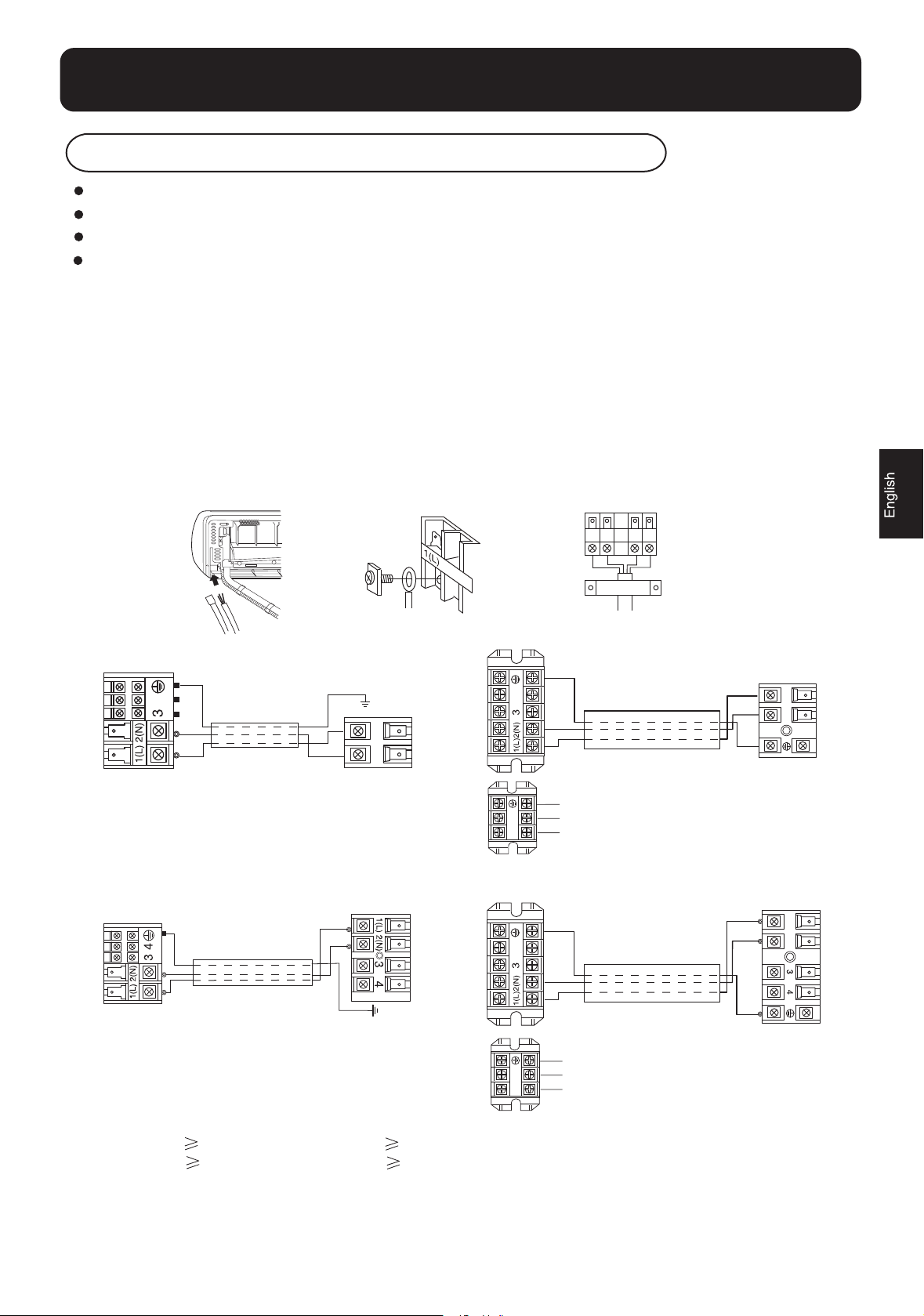
Loosen the screws and insert the cable ends fully into terminal block, then tighten the screws.
Pull the cable slightly to make sure the cables have been properly inserted and tightened.
After the cable connection, never fail to fasten the connected cable with the wiring cover.
Note: When connecting the cable, confirm the terminal number of indoor and outdoor units carefully. If wiring
is not correct, proper operation can not be carried out and will cause defect.
1. If the supply cord is damaged, it must be replaced by the manufacturer or its service agent or a similar
qualified person. The type of connecting wire is
2. If the fuse on PC board is broken please change it with the type of T. 3.15A/250V.
3. The wiring method should be in line with the local wiring standard.
4. After installation, the power plug should be easily reached.
5. A breaker should be incorporated into fixed wiring. The breaker should be all-pole switch and the
distance between its two contacts should be not less than 3mm.
H05/07RN-F or 245IEC57(YZW).
.
Indoor unit
Indoor unit
Power cable:
-mod 09-12:
-mod 18-24:
HSU-09C12
HSU-12C12
HSU-09C13
HSU-12C13
HSU-12C03/Z1
HSU-09C03/Z1
3G1.0mm
3G2.0mm
2
2
(1 )
L
)
2
(
N
Outdoor unit
Outdoor unit
Connecting cable:
-mod 09-12:
-mod 18-24:
3G1.0mm
3G2.0mm
Indoor unit
Indoor unit
2
2
4
L(1
)
(2
N
)
Outdoor unit
HSU-18C13
G
G
UL
{
P
R
E
W
O
P
GULP REWOP
{
HSU-18CK03
HSU-22C13
HSU-24C13
1
(
L
)
(2
N
)
Outdoor unit
N
N
L
L
4
G
N
L
L N
Page 6

Forced fastening without careful centering
may damage the threads and cause a
leakage of gas.
Pipe Diameter ( )
Liquid side 6.35mm(1/4")
Gas side 9.52mm(3/8")
Fastening torque
18N.m
40N.m
Gas side 12.7mm(1/2") 50N.m
Gas side 15.88mm(5/8")
60N.m
Liquid side 9.52mm(3/8")
40N.m
Outdoor unit
6
Outdoor unit
1.Installation of Outdoor Unit
Install according to
Drawing for the installation of indoor and outdoor units
2.Connection of pipes
To bend a pipe, give the roundness as large as possible not to crush the pipe
Connecting the pipe of gas side first makes working easier.
The max vertical distance between the indoor unit and the outdoor unit is 5 m.
Half union
Spanner
Be careful that matters, such as wastes of sands, etc. shall not enter the pipe.
Flare nut
Torque wrench
3.Connection
Use the same method on indoor unit. Loosen the screws on terminal block and insert the plugs fully into
terminal block, then tighten the screws.
Insert the cable according to terminal number in the same manner as the indoor unit.
If wiring is not correct, proper operation can not be carried out and controller may be damaged.
Fix the cable with a clamp.
4.Attaching Drain-Elbow
If the drain-elbow is used, please attach it as
figure. (Note: Only for heat pump unit.)
Page 7

Outdoor unit
HSU-12C13
HSU-09C13
HSU-24C13
HSU-12C03/Z1
HSU-09C03/Z1
HSU-12C12
HSU-09C12
7
5.Purging Method:
Push the air out of the indoor unit
and piping as followes:
(1) Remove the valve cap on 2-way
valve in outdoor unit.
(2) Loosen by 1/2 turn the flare nut of
gas pipe, which is conneted to
3-way valve.
(3) Loosen 2-way valve by 90o using
hexagon wrench, and after approx.
10 sec tighten it up. Gas comes out
through flare nut on wide pipe. If no
gas is discharged, tighten flare nut
with specified torque.
(4) Open 2-way and 3-way valves
using specified torque.
(5) Tighten the caps on the valves
with specified torque.
2-way valve
6.35mm(1/4")
HSU-18C13
HSU-18CK03
3-way valve
12.7mm(1/2")
2-way valve
6.35mm(1/4")
9.52mm(3/8")
3-way valve
9.52mm(3/8")
12.7mm(1/2")
15.88mm(5/8")
Tighten torque N.m
Valve rod
Valve cap
When connecting pipe exceeds 5 meters, 20g or 60g(only for 22k) refrigerant
shall be added per exceeding meter . Charge according to the following list.
Piping length
Additional amount
Piping length
Additional amount
Note: When extending piping, air inside piping shall be removed by using external
refrigerant gas, charge according to the following list.
Brand new outdoor unit is charged 50g or 80g(only for 22k and 24k unit) more refrigerant than regulated weight.
Only for first installation, this extra 50g or 80g(only for 22k and 24k unit) can be used to purge air in pipes.
7-9
20-25
for 9k 12k 18k
5m 7m
No need
for 22k 24k
5m 7m
No need
40g
120g
10m
100g
10m
300g
HSU-22C13
During this procedure, 50g or 80g(only for 22k and 24k unit) refrigerant will be discharged in piping.
(This must be strictly controlled within 90o and 10 sec.)
Page 8

1.Power Source Installation
8
The power source must be exclusively used for air conditioner. (Over I0A)
In the case of installing an air conditioner in a moist place, please install an
earth leakage breaker.
For installation in other places, use a circuit breaker as far as possible.
2.Cutting and Flaring Work of Piping
Pipe cutting is carried out with a pipe cutter and burs must be removed.
After inserting the flare nut, flaring work is carried out.
Pipe diameter( )
A
Flare tooling die
Correct
Liquid side
Liquid side
Gas side
Gas side 12.7mm(1/2")
Gas side 15.88mm(5/8")
6.35mm(1/4")
9.52mm(3/8") 1.0~1.8
9.52mm(3/8")
Incorrect
Lean Damage of flare Crack Partial Too outside
3.On Drainage
Please install the drain hose so as to be downward slope without fail.
Please don't do the drainage as shown below.
Size A(mm)
0.8~1.5
1.0~1.8
1.2~2.0
1.4~2.2
Less than 5cm
It becomes high
midway.
The end is immersed
in water.
It waves. The gap with the ground
is too small
There is the bad smell
from a ditch
Please pour water in the drain pan of the indoor unit, and confirm that drainage is
carried out surely to outdoor.
In case that the attached drain hose is in a room, please apply heat insulation
to it without fail.
Check for Installation and Test Run
Please kindly explain to our customers how to operate through the instruction manual.
Check Items for Test Run
Gas leak from pipe connecting?
Heat insulation of pipe connecting?
Are the connecting wirings of
indoor and outdoor firmly inserted
to the terminal block?
Is the connecting wiring of indoor
and outdoor firmly fixed?
Put check mark in boxes
Is drainage securely carried out?
Is the earth line securely
connected?
Is the indoor unit securely fixed?
Is power source voltage abided
by the code?
Is there any noise?
Is the lamp normally lighting?
Are cooling and heating (when
in heat pump) performed normally?
Is the operation of room temperature
regulator normal?
Page 9

Manual de instalación del Acondicionador de Aire
9
Lea este manual antes de la instalación
Explicar suficientemente los procesos de
funcionamiento al usuario según este manual
Herramientas necesarias para la instalación
1. Destornillador
2. Sierra
3. Taladro
4. Llaves fijas (17, 19 y 26 mm)
Accesorios
No. Accesorios
1
2
3
4
5
6
7
Control remoto
Pila seca R-03
Placa de montaje
Manguera de drenaje
Clavo de acero, cemento 6
4X25
tapa de plástico
Tornillo
Codo de drenaje
4X50
5. Llaves dinamométricas (17, 22 y 26 mm)
6. Cortador de tubo
7. Herramienta de abocardar
8. Cuchillo
Planos para la Instalación de unidad interior y exterior
Num. de
unidades
1
Piezas opcionales para tubería
Marca
2
1
1
4
1
Soporte (lado izquierdo) con tornillos
Cable eléctrico de conexión
Material aislante del calor
Tapa de agujero para tubos
Nombre del elemento
Cinta no adhesiva
Cinta adhesiva
para interior y exterior
Manguera de drenaje
más de 10 cm
9. Alicates
10. Detector de fugas de gas o
solución de agua jabonosa
más de 5 cm
Debe prestarse atención a que
la manguera de drenaje no
quede elevada
11. Cinta de medir
12. Escariador
más de 10 cm
A
8
9
10
Cubierta
Cojín
Placa de soporte
de tubo
1
4
1
Las marcas de " " a " " en la figura son los números de las piezas
La distancia entre la unidad interior y el suelo debe ser superior a 2 m.
Disposición de las tuberías
Izquierda
Trasera izquierda
Trasera derecha
Derecha
Debajo
más de 10 cm
más de 60 cm
más de 10 cm
D
más de 15 cm
Page 10

140 415 140
10
Dimensiones de fijación
en el suelo de la unidad
exterior (Unidad: mm)
HSU-09C12
HSU-12C12
HSU-09C13
HSU-12C13
HSU-09C03/Z1
HSU-12C03/Z1
280
140
Dimensiones de fijación
en el suelo de la unidad
exterior (Unidad: mm)
500 140
HSU-18C13
HSU-18CK03
256
113.5
Dimensiones de fijación
en el suelo de la unidad
exterior (Unidad: mm)
583
113.5
HSU-22C13
HSU-24C13
319.5
Fijación de la unidad exterior
Fijar la unidad a hormigón o bloquear con pernos (Ø10 mm ) y tuercas firme y
horizontalmente.
Al fijar la unidad a la superficie de la pared, el tejado o la parte superior del tejado,
fijar un soporte de forma segura con clavos o cables para el caso de que se produzca
un terremoto o rachas de viento muy fuertes.
Si las vibraciones pueden afectar a la casa, fijar la unidad colocando una esterilla a
prueba de vibraciones.
Unidad Interior Unidad Exterior
Selección de lugar de la instalación
La zona deberá ser resistente, no provocar vibraciones, y ser suficientemente
robusta para soportar la unidad.
La zona no se verá afectada por el calor ni el vapor generados en las cercanías,
y la entrada y la salida de la unidad no se verán perturbadas.
La zona podrá drenarse con facilidad, y las tuberías puedan podrán conectarse
con la unidad exterior.
La zona será una en la que el aire frío pueda difundirse por toda una sala.
La zona estará cerca de una toma de tensión, con suficiente espacio alrededor.
(Consultar los planos).
La zona será una en la que se podrá mantener una distancia superior a 1 m
de televisores, radios, aparatos inalámbricos y lámparas fluorescentes.
En el caso de fijar el mando a distancia en una pared, la zona será una en la
que la unidad interior podrá recibir señales cuando se enciendan las lámparas
fluorescentes de la sala.
La zona deberá estar lo más resguardada posible de la lluvia, de la
luz solar directa y deberá estar suficientemente ventilada.
La zona podrá soportar la unidad y no aumentará las vibraciones ni
el ruido.
La zona deberá ser una en la que el ruido y el viento emitido no
provoquen perturbaciones a los vecinos.
La zona será unaen la que unadistancia marcada esté disponible,
tal como se ilustra en la figura anterior.
Alimentación
Antes de introducir el enchufe en la toma, verificar que no hay errores de tensión. La alimentación es la misma que la de la placa de características
correspondiente.
Instalar un circuito de bifurcación exclusivo.
Se situará un receptáculo a una distancia a la que pueda llegar el cable de alimentación. No alargar el cable cortándolo.
Selección del tubo
En esta unidad, tanto las tuberías de gas como las tuberías de líquido estará
aisladas, ya que se producen temperaturas bajas durante el funcionamiento.
Usar piezas opcionales para él conjunto de tuberías o tuberías recubiertas
con material aislante equivalente.
Tubo liquido ( )
Tubo gas ( )
09
6.35mm(1/4")
9.52mm(3/8")
12,18
6.35mm(1/4")
12.7mm(1/2")
22,24
9.52mm(3/8")
15.88mm(5/8")
Page 11

Unidad Interior
11
1 Montaje de la placa de montaje y situación de orificio en la pared
Cuando se monte la placa de montaje por vez primera
1 Ejecutar, según los pilares o dinteles circundantes, una nivelación adecuada para la placa que se
vaya a montar en la pared; a continuación, ajustar la placa con una punta de acero.
2 Asegurarse que una vez más del nivel adecuado de la placa colgando un hilo con un peso desde
la parte central superior de dicha placa; a continuación asegurar la placa con una punta de acero
de enganche.
3 Encontrar la posición del orificio de la pared A usando cinta de medición.
60mm
B=
A=145mm
30mm
Cuando se sujeta la placa de montaje a la barra lateral y al dintel
Fijar una barra de montaje, de venta por separado, al dintel y la barra lateral; a continuación
ajustar la placa a la barra de montaje fija.
Consultar el artículo anterior, "Cuando se monte la placa de montaje por vez primera",
para la situación del orificio en la pared.
2 Perforación de la pared y ajuste de la tapa del orificio de la tubería
Hacer un orificio de 60 mm de diámetro,
descendiendo levemente hacia el exterior de la
pared
Instalar la tapa de la perforación de la tubería y
sellarlo con masilla tras su instalación.
Lado interior
Orificio de pared
60mm
(Sección del orificio de la pared) Tubo
del orificio de la tubería
Lado exterior
Grosor de pared
3 Instalación de la unidad interior
Esquema de la tubería
[Tubería trasera]
Colocar las tuberías y la manguera de desagüe; a continuación sujetarlas con la cinta adhesiva.
[tubería posterior izquierda izquierda ]
En caso de tubería en el lado izquierdo, cortar, con una pinza la tapa para la tubería izquierda.
En el caso de tubería en la parte posterior izquierda, curvar las tuberías de acuerdo con la dirección de la canalización
según la marca de la tubería posterior izquierda del orificio, que está señala en los materiales de aislamiento térmico.
Page 12

Unidad Interior
12
1. Introducir la manguera de desagüe en el dintel de los materiales de aislamiento térmico de la unidad interior.
2. Introducir el cable eléctrico interior/exterior desde la parte trasera de la unidad interior y sacarlo en el lado
delantero; a continuación conectarlos
3. Aplicar la cara de la junta abocardada con aceite refrigerante y conectar las tuberías.
Tapar totalmente la pieza de conexión con materiales de aislamiento térmico y verificar que se utiliza cinta
adhesiva.
Material aislante de calor
Tapa para tubería derecha
Tapa para tubería bajo canalización
Fijar con cinta adhesiva
El cable eléctrico interior/exterior y la manguera de desagüe deben unirse con la tubería de refrigerante usando la
cinta protectora.
Tapa para tubería izquierda
Manguera de
desagüe
Tuberías
Placa apoyatubo
Cable eléctrico interior/exterior
[Otras tuberías de dirección ]
Cortar, con una pinza, la tapa para la tubería de acuerdo con la dirección de la tubería y, a continuación curvar la
tubería según la posición del orificio en la pared. Al curvar, prestar mucha atención para no romper las tuberías.
Conectar de antemano el cable eléctrico interior/exterior y, a continuación, sacar el conectado al aislamiento térmic
de la pieza de conexión.
Ajuste de la carcasa de la unidad interior
Colgar con seguridad la unidad en las muescas de la placa de
montaje. Mover la unidad de lado a lado para verificar si está
firmemente sujeta.
Para fijar la carcasa en la placa de montaje, elevar el aislante de la
carcasa desde la parte inferior y hacerlo descender de forma
perpendicular.
4 Conexión del cable eléctrico exterior/interior
Retirada de la tapa del cableado
Quitar la tapa de terminales situada en la esquina inferior derecha de la unidad
interior y, a continuación, quitar la tapa del cableado retirando los tornillos
Al conectar el cable después de instalar la unidad interior
1. Introducir desde el exterior de la sala el cable en el lado izquierdo del orificio en la pared,
en el que ya existía la tubería.
2. Sacar el cable en el lado delantero y conectar el cable realizando un bucle
Page 13

H05/07RN-F o
Unidad Interior
HSU-22C13
13
Al conectar el cable antes de instalar la unidad interior
Introducir el cable desde la parte trasera de la unidad y, a continuación, sacarlo en el lado delantero.
Aflojar los tornillos e introducir totalmente los extremos del cable en la regleta de terminarles y apretar
luego los tornillos.
Tirar suavemente del cable para verificar que los cables han sido adecuadamente introducidos y tensados.
Después de conectar los cables, no dejar jamás de sujetar el cable conectado con la tapa del cableado.
Nota: Al conectar el cable, confirmar meticulosamente el número del terminal de las unidades interior y
exterior. Si el cableado no es correcto, no podrá haber un funcionamiento correcto y puede estropearse
el controlador.
1. Si el cable de alimentación está dañado, debe ser sustituido por el fabricante o su agente de
mantenimiento o una persona con cualificación similar. El tipo de cable de conexión es
245IEC57(YZW).
2. Si el fusible de la placa PC está roto, cambiarlo por uno del tipo T.3. 1 5A/250V.
3. El método de cableado debe ser conforme a la norma local sobre cableado.
4. Después de la instalación, se debe poder llegar con facilidad al enchufe de red.
5. Un triturador se debe incorporar en el cableado fijo. El triturador debe ser del todo-poste y la
distancia entre sus dos contactos debe ser no menos de 3mm.
4
Indoor unit
HSU-09C12
HSU-12C12
HSU-09C13
HSU-12C13
HSU-12C03/Z1
Indoor unit
HSU-09C03/Z1
Cable de electricidad:
-mod 09-12:
-mod 18-24:
3G1.0mm
3G2.0mm
Outdoor unit
Outdoor unit
Connecting cable:
2
-mod 09-12:
2
-mod 18-24:
1(L)
2(N)
3G1.0mm
3G2.0mm
Indoor unit
2
Indoor unit
2
4
1(L)
2(N)
Outdoor unit
G
{
N
N
L
L
4
G
N
L
L N
HSU-18C13
HSU-18CK03
POWER PLUG
HSU-24C13
{
POWER PLUG
1(L)
2(N)
Outdoor unit
Page 14

Una sujeción forzada con un
centrado descuidado puede
dañar las roscas y provocar fugas
de gas.
Tener cuidado para que no entre ningún material extraño, por ejemplo, arenas, agua, etc. en los tubos.
6.35mm(1/4")
9.52mm(3/8")
18N.m
40N.m
12.7mm(1/2")
50N.m
15.88mm(5/8")
60N.m
Diámetro del tubo
Par de apriete
lado líquido
lado gas
lado gas
lado gas
9.52mm(3/8")
lado líquido
40N.m
Unidad Exterior
14
1 Instalación de la unidad exterior
Instalar de acuerdo con el Plano para la instalación de las unidades interior y exterior
2 Conexión de los tubos
Para curvar una tubería, realizar una redondez lo más amplia posible con el fin de evitar
roturas de la tubería.
Si se conecta en primer lugar la tubería de gas el trabajo resulta más sencillo.
La distancia vertical máx. entre la unidad interior y la unidad exterior es 5 m
Media unión
Llave
Tuerca
llave dinamométrica
3 conexión
Usar el mismo método en la unidad interior. Aflojar
los tornillos de la regleta e introducir los terminales
en el bloque y apretar luego los tornillos.
Introducir el cable de acuerdo al número del terminal
de la misma forma que la unidad interior.
Si el cableado no es correcto, no podrá haber un
funcionamiento correcto y puede estropearse el controlador.
Sujetar el cable con una regleta.
4 Acoplamiento de un codo de desagüe
Si se utiliza un codo de desagüe, acoplarlo del modo
que se muestra en la figura.
Nota: Sólo para la unidad de bomba de calor.
manguera de desagüe
Codo de desagüe
Page 15

Unidad Exterior
válvu a de 3 vías
l
15
5.
Método de purga:
Extraer el aire de la unidad interior y la tubería como se describe:
(1) Quite la tapa de la válvula de
dos vías en la unidad interior.
(2) Aflojar media vuelta la tuerca cónica
del tubo de gas, el cual está conectado a la
válvula de tres vías.
válvula de 2 vías
6.35mm(1/4")
12.7mm(1/2")
(3) Aflojar 90° (un cuarto de vuelta) la válvula de
dos vías utilizando una llave hexagonal y luego de
aproximadamente 10 segundos, ajustarla. El gas sale
a través de la tuerca cónica en el tubo ancho. Si no hay
emisión de gas, ajuste la tuerca cónica con la fuerza de
torsión especificada.
(4) Abrir las válvulas de dos vías y tres vías usando la
fuerza de torsión especificada.
(5) Ajustar las tapas en las válvulas con la fuerza de torsión especificada.
Torsión de ajuste N.m
Vástago de válvula 7-9
Tapa de válvula 20-25
Cuando el tubo de conexión excede los 5 metros, se deben agregar 20g or 60g de refrigerante por
metro
excedente. Cargar según la siguiente lista.
HSU-18C13
HSU-18CK03
válvula de 2 vías
6.35mm(1/4")
9.52mm(3/8")
válvula de 3 vías
9.52mm(3/8")
12.7mm(1/2")
15.88mm(5/8")
HSU-09C12
HSU-12C12
HSU-09C13
HSU-12C13
HSU-22C13
HSU-24C13
HSU-09C03/Z1
HSU-12C03/Z1
9k 12k 18k
Longitud de tubo 5m 7m 10m
Cantidad adicional No se necesita
22k 24k
Longitud de tubo 5m 7m 10m
Cantidad adicional No se necesita
Nota: Cuando se extiende el tubo, el aire dentro del tubo será extraído usando gas refrigerante
externo, cargar según la siguiente lista.
En el caso de las unidades exteriores nuevas, se les debe cargar 50g o 80g (sólo para unidades de
22k y 24k) más de refrigerante que el peso regular. Se deben usar estos 50g o 80g (sólo para
unidades de 22k y 24k) para purgar el aire de los tubos sólo en la primera instalación.
Durante este procedimiento, se despedirán 50g o 80g (sólo para unidades de 22k y 24k) de
refrigerante en el tubo. (Esto debe ser estrictamente controlado within 90° and 10 sec.)
40g
120g
100g
300g
Page 16

1 Instalación de la alimentación siguiente:
A(mm)
6.35mm(1/4")
9.52mm(3/8")
0.8~1.5
1.0~1.8
12.7mm(1/2")
1.2~2.0
lado líquido
lado gas
lado gas
Diámetro del tubo ( )
Tamuño
15.88mm(5/8")
1.4~2.2
lado gas
9.52mm(3/8")
1.0~1.8
lado líquido
16
La alimentación debe ser exclusiva para el aire acondicionado. (Más de 1OA)
En caso de instalar un aire acondicionado en un lugar húmedo, instalar un disyuntor de
fugas de tierra.
Para instalar en otros lugares, utilizar un disyuntor tan lejos como sea posible.
2 Corte y abocardado de las tuberías
El corte de las tuberías se lleva a cabo con un cortatubos y se deben eliminar las rebabas.
Después de introducir la tuerca, se efectúa la labor de abocardado.
parcial
Correcto
Cavidad del mandril
Inclinación
Abocardado
estropeado
Incorrecto
rotura
3 Sobre el desagüe
Instalar la manguera de desagüe de modo que se dirija hacia abajo sin caer.
No realizar el desagüe del modo mostrado a continuación.
demasiado
reborde
menos de 5 cms
Sube a medio camino El extremo se introduce en agua Produce olas La distancia al suelo
es demasiado pequeña
Emite olores desagradables
desde una zanja
Verter agua en la cubeta de drenaje de la unidad interior y confirmar que el drenaje se
efectúa con seguridad al exterior
En caso de que la manguera de desagüe acoplada se halle en una habitación, aplicar a
la misma aislamiento térmico total.
Verificación de instalación y puesta a punto
Explicar amablemente a nuestros clientes el modo de utilización del aparato empleando el manual de instrucciones.
Verificar elementos para la puesta apunto
¿Hay fuga de gas en la conexión de las tuberías?
¿Se ha aislado térmicamente la conexión de las
tuberías?
¿Están firmemente introducido en la regleta de
terminales los hilos de conexión de la unidad
interior y exterior?
¿Se ha fijado con seguridad el hilo de conexión
de la unidad interior y exterior?
¿Se lleva a cabo de forma segura el desagüe?
¿Está conectada de forma segura la toma de
tierra?
¿Está firmemente sujeta la unidad interior?
¿Soporta el código el voltaje de la alimentación?
¿Se produce algún ruido?
(Colocar una señal en las casillas)do el manual de instrucciones.
¿Se ilumina la lámpara con normalidad?
¿Se llevan a cabo con normalidad la refrigeración
y la calefacción (en bomba de calor)?
¿Es normal el funcionamiento del regulador de la
temperatura ambiente?
 Loading...