

Page 1
Installation Manual of Room Air Conditioner
Read this manual before installation
Explain sufficiently the operating means to the user
according to this manual.
Necessary Tools for Installation
1.Driver
2.Hacksaw
3.Hole core drill
4.Spanner(17,19 and 26mm)
Accessory parts
No. Accessory parts
Remote controller
1
2
3
4
5
6
7
8
9
R-03 dry battery
Mounting plate
Drain hose
Steel nail, cement
4X25
Screw
Plastic cap
Cover
Cushion
Pipe supporting plate
4X50
Number
of
articles
1
2
1
1
6
4
1
4
1
5.Torque wrench(17mm,22mm,26mm)
6.Pipe cutter
7.Flaring tool
8.Knife
9.Nipper 12.Reamer
10.Gas leakage detector or
soap-and-
water solution
11.Measuring tape
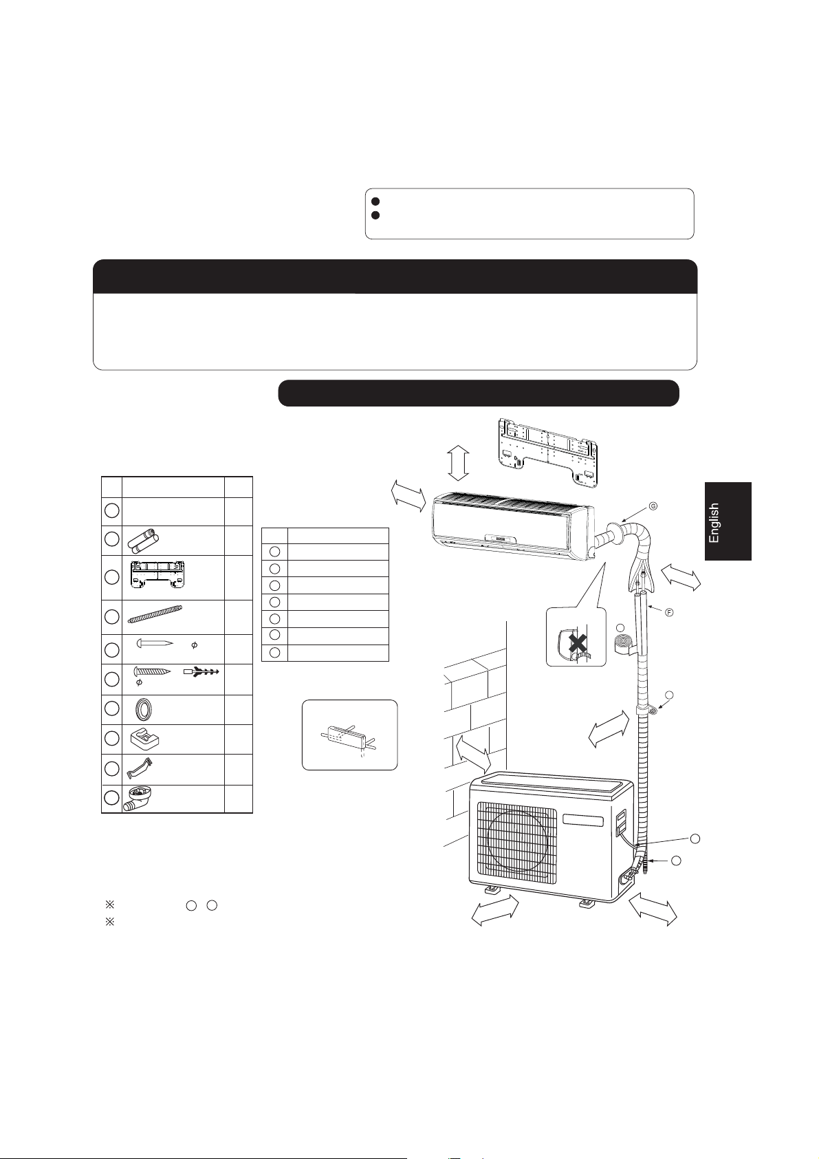
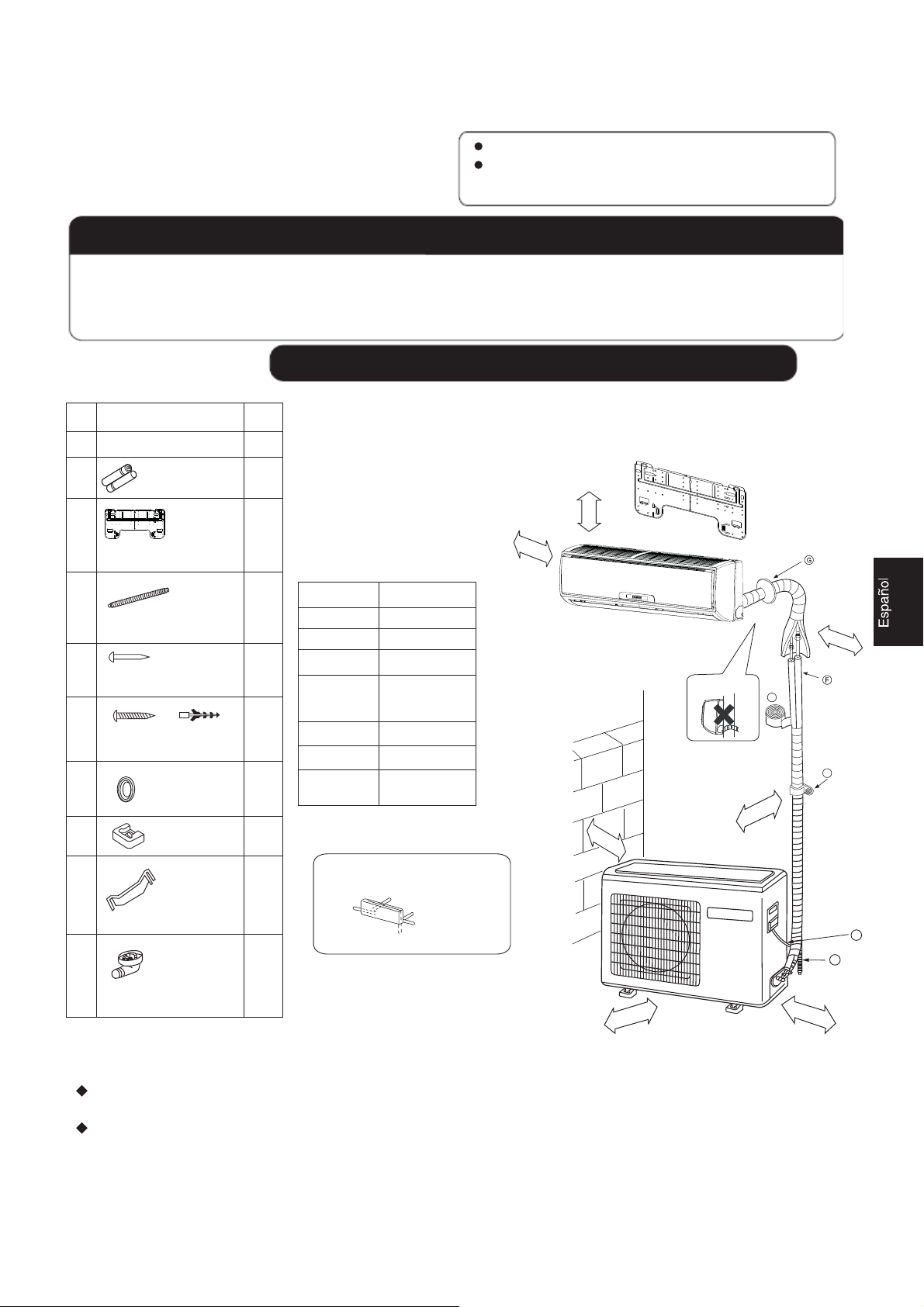
Drawing for the installation of indoor and outdoor units
mc5nahterom
mc01nahterom
Optional parts for piping
Mark
Parts name
A
Non-adhesive tape
Adhesive tape
B
Saddle(L.S) with screws
C
Connecting electric cable
D
for indoor and outdoor
Drain hose
E
F
Heating insulating material
Piping hole cover
G
Arrangement of piping directions
Left
Rear left
Bel
ow
Rear
right
Right
Attention must be paid to
the rising up of drain hose
mc01nahterom
mc01nahterom
A
C
mc0
1
nahterom
10
Drain-elbow
The marks from to in the figure are the parts numbers.
A
1
G
The distance between the indoor unit and the floor should be
more than 2m.
No.0010516146
D
E
mc06
na
hterom
1nahterom
mc5
Page 2
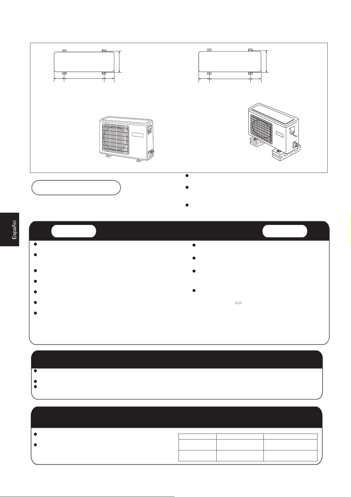
140
500 140
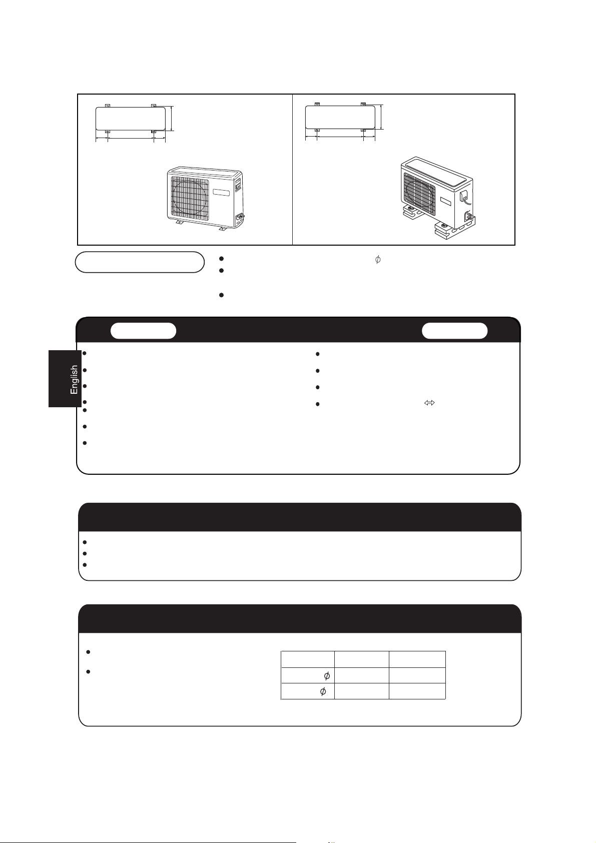
Floor fixing dimensions
of the outdoor unit
(Unit:mm)
256
115
580
Floor fixing dimensions
of the outdoor unit
(Unit:mm)
115
5.913
HSU-07HEA03/R2
HSU-09HEA03/R2
HSU-09HEA103
HSU-12HEA03/R2
HSU-18HEA03/R2
Fixing of outdoor unit
/R2
Fix the unit to concrete or block with bolts( 10mm) and nuts firmly and horizontally.
When fitting the unit to wall surface, roof or rooftop, fix a supporter surely with nails
or wires in consideration of earthquake and strong wind.
If vibration may affect the house, fix the unit by attaching a vibration-proof mat.
Indoor Unit
Place, robust not causing vibration, where the body can be supported
sufficiently.
Place, not affected by heat or steam generated in the vicinity, where
inlet and outlet of the unit are not disturbed.
Place, possible to drain easily, where piping can be connected with the
outdoor unit.
Place, where cold air can be spread in a room entirely.
Place, nearby a power receptacle, with enough space around. (Refer
to drawings).
Place where the distance of more than lm from televisions, radios,
wireless apparatuses and fluorescent lamps can be left.
In the case of fixing the remote controller on a wall, place where the
indoor unit can receive signals when the fluorescent lamps in the room
are lightened.
Selection of Installation Place
HSU-22HEA03/R2
Outdoor Unit
Place, which is less affected by rain or direct sunlight and is
sufficiently ventilated.
Place, possible to bear the unit, where vibration and noise are
not increased.
Place, where discharged wind and noise do not cause a
nuisance to the neighbors.
Place, where a distance marked is available as illustrated
in the above figure.
Power Source
Before inserting power plug into receptacle, check the voltage without fail. The power source is the same as the corresponding name plate.
Install an exclusive branch circuit of the power.
A receptacle shall be set up in a distance where the power cable can be reached. Do not extend the cable by cutting it.
Selection of pipe
To this unit, both liquid and gas pipes shall be insulated
as they become Iow temperature in operation.
Use optional parts for piping set or pipes covered with
equivalent insulation material.
Liquid pipe ( )
Gas pipe ( ) 9.52mm(3/8")
1
For 07 09 12
6.35mm(1/4")
For 18 22
6.35mm(1/4")
12.7mm(1/2")
Page 3
Indoor unit
Indoor unit
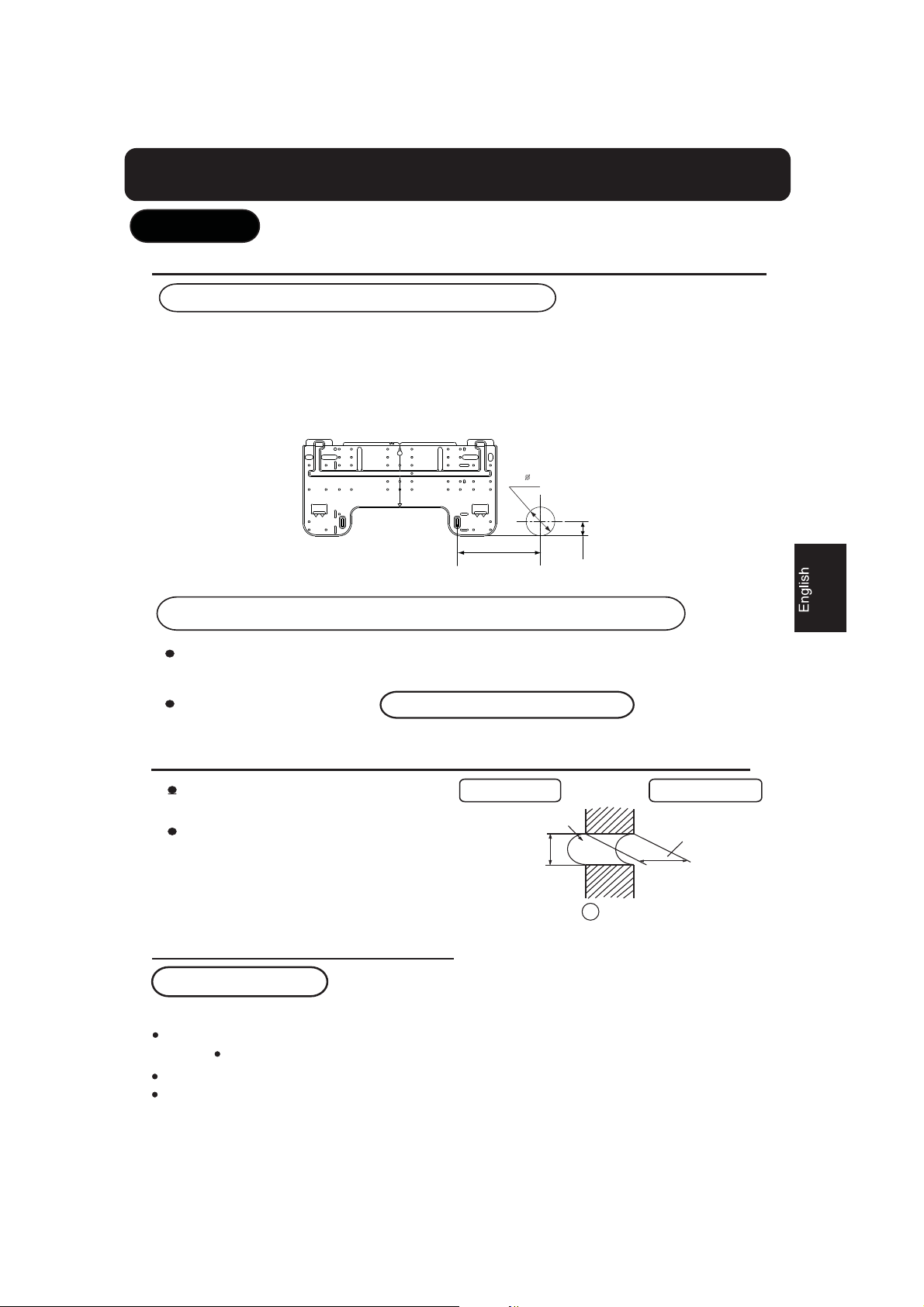
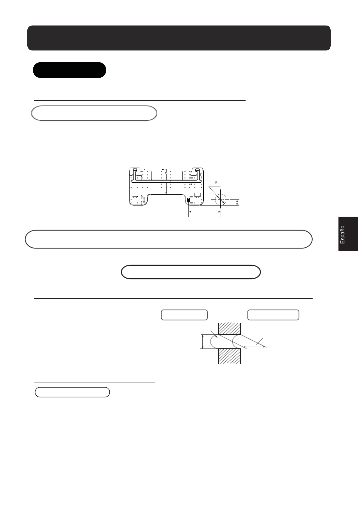
1.Fitting of the Mounting Plate and Positioning of the wall Hole
When the mounting plate is first fixed
1.Carry out, based on the neighboring pillars or lintels, a proper leveling for the plate to be
fixed against the wall, then temporarily fasten the plate with one steel nail.
2. Make sure once more the proper level of the plate, by hanging a thread with a weight from
the central top of the plate, then fasten securely the plate with the attachment steel nail.
3. Find the wall hole location A using a measuring tape
B= 60mm
A=145mm
30mm
When the mounting plate is fixed side bar and lintel
Fix to side bar and lintel a mounting bar, Which is separately sold, and then fasten
the plate to the fixed mounting bar.
Refer to the previous article, " When the mounting plate is first fixed ", for the
position of wall hole.
2.Making a Hole on the Wall and Fitting the Piping Hole Cover
Make a hole of 60 mm in diameter,
slightly descending to outside the wall.
Install piping hole cover and seal it
off with putty after installation
Indoor side
Wall hole
60mm
(Section of wall hole)
G
Piping hole pipe
Outdoor side
Thickness
of wall
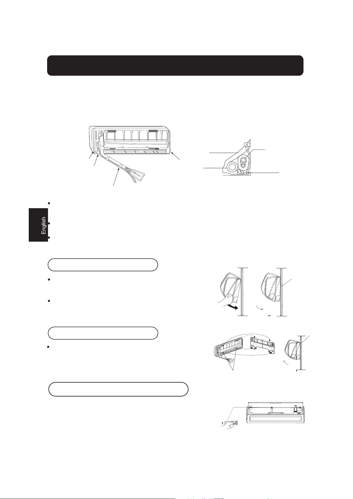
3.Installation of the Indoor Unit
Drawing of pipe
[ Rear piping ]
Draw pipes and the drain hose, then fasten them with the adhesive tape
[ Left Left-rear piping ]
In case of left side piping, cut away, with a nipper, the lid for left piping.
In case of left-rear piping, bend the pipes according to the piping direction to the mark of hole for left-rear
piping which is marked on heat insulation materials.
2
Page 4
Indoor unit
1. Insert the drain hose into the dent of heat insulation materials of indoor unit.
2. Insert the indoor/outdoor electric cable from backside of indoor unit, and pull it out on the front side, then
connect them.
3. Coat the flaring seal face with refrigerant oil and connect pipes.
Cover the connection part with heat insulation materials closely, and make sure fixing with adhesive tape
Heat insulation
material
Lid for right piping
Lid for under piping
Fix with adhesive tape
Indoor/outdoor electric cable and drain hose must be bound with refrigerant piping by protecting tape.
Lid for left piping
Drain hose
Piping
Indoor/outdoor
electric cable
[Other direction piping]
Cut away, with a nipper, the lid for piping according to the piping direction and then bend the pipe according
to the position of wall hole. When bending, be careful not to crash pipes.
Connect beforehand the indoor/outdoor electric cable, and then pull out the connected to the heat insulation
of connecting part specially.
Fixing the indoor unit body
Hang surely the unit body onto the upper notches of the
mounting plate. Move the body from side to side to verify
its secure fixing.
In order to fix the body onto the mounting plate,hold up
the body aslant from the underside and then put it down
perpendicularly.
mounting plate
Unloading of indoor unit body
When you unload the indoor unit,please use your hand to arise
the body to leave agraffe,then lift the bottom of the body outward
slightly and lift the unit aslant until it leaves the mounting plate.
Easily-demount cleaning of indoor unit
Inlet grille can be taken down
Open the inlet grille,press the button of unlock in the left,then push
it out of the socket and take out the inlet grille.
3
mounting plate
agraffe
Page 5
Indoor unit
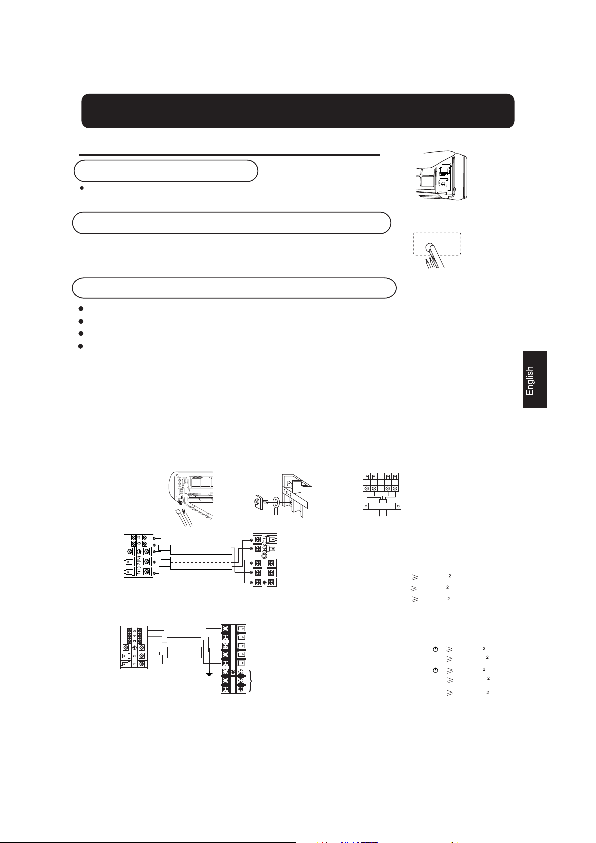
Connecting the indoor/outdoor Electric Cable
Removing the wiring cover
Remove terminal cover at right bottom corner of indoor unit, then
take off wiring cover by removing its screws.
When connecting the cable after installing the indoor unit
1. Insert from outside the room cable into left side of the wall hole, in which
the pipe has already existed.
2. Pull out the cable on the front side, and connect the cable making a loop.
When connecting the cable before installing the indoor unit
Insert the cable from the back side of the unit, then pull it out on the front side.
Loosen the screws and insert the cable ends fully into terminal block, then tighten the screws.
Pull the cable slightly to make sure the cables have been properly inserted and tightened.
After the cable connection, never fail to fasten the connected cable with the wiring cover.
Note: When connecting the cable, confirm the terminal number of indoor and outdoor units carefully. If wiring
is not correct, proper operation can not be carried out and will cause defect.
1. If the supply cord is damaged, it must be replaced by the manufacturer or its service agent or a similar
qualified person. The type of connecting wire is H05/07RN-F or 245IEC57(YZW).
2. If the fuse on PC board is broken please change it with the type of T. 3.15A/250V.
3. The wiring method should be in line with the local wiring standard.
4. After installation, the power plug should be easily reached.
5. A breaker should be incorporated into fixed wiring. The breaker should be all-pole switch and the
distance between its two contacts should be not less than 3mm.
Indoor unit
Indoor unit
HSU-07HEA03/R2
HSU-09HEA03/R2
HSU-09HEA103/R2
HSU-12HEA03/R2
HSU-18HEA03/R2
HSU-22HEA03/R2
Outdoor unit
21
3
4
5
L
N
Outdoor unit
3
4
POWER
Power cable:
-mod 07-09-12:
- mod 18:
-mod 22:
connecting wiring:
-mod 07-09-12:
-mod 18:
3G1.0mm
3G2.5mm
3G2.5mm
LǃNǃ :
3ǃ4:
LǃNǃ
3ǃ4:
-mod 22:
:
3G1.0mm
2X0.75mm
3G2.5mm
2X0.75mm
6G0.75mm
4
Page 6
Outdoor unit
1.Installation of Outdoor Unit
Install according to
Drawing for the installation of indoor and outdoor units
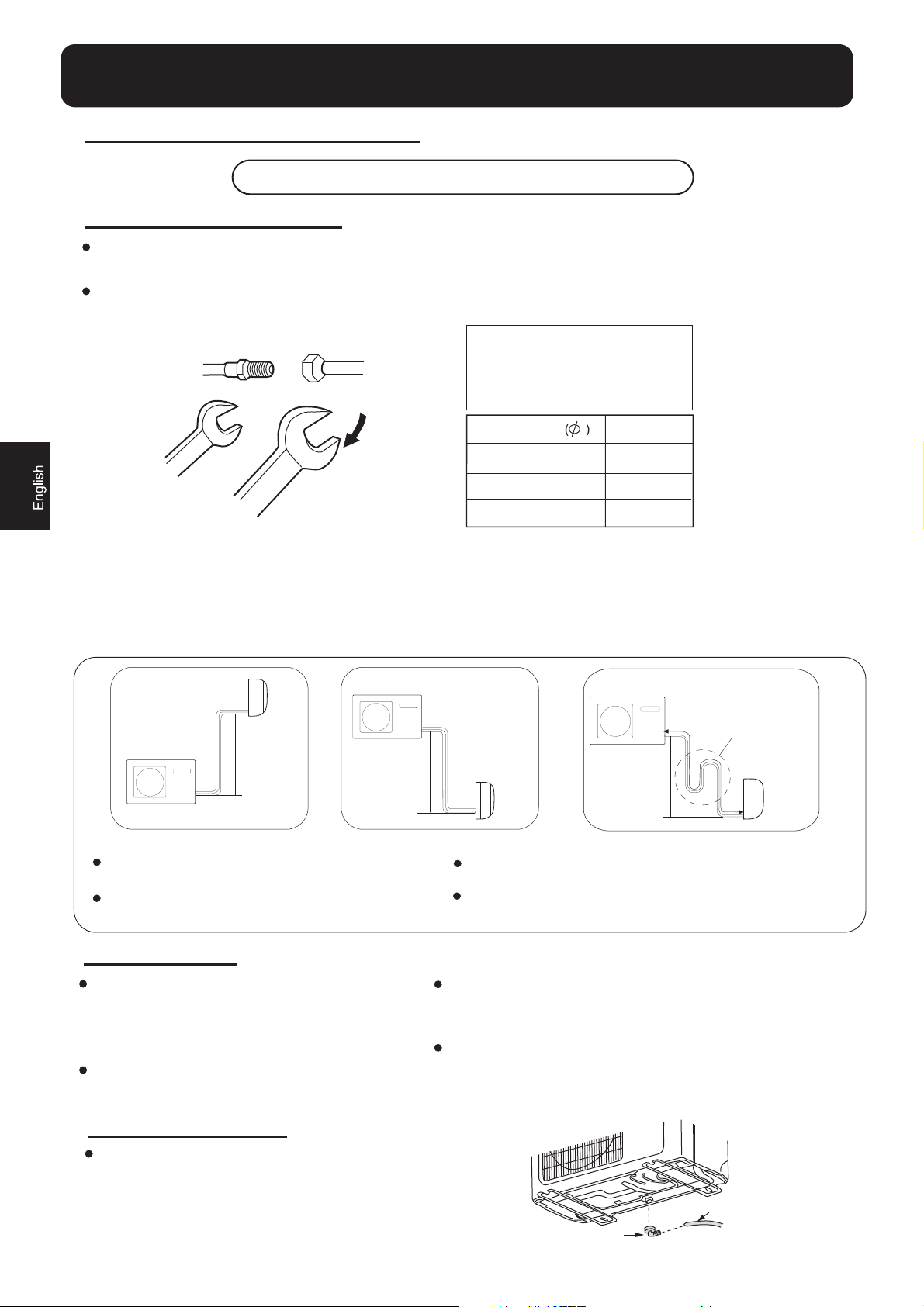
2.Connection of pipes
To bend a pipe, give the roundness as large as possible not to crush the pipe ,and the bending radius
should be 30 to 40 mm or longer.
Connecting the pipe of gas side first makes working easier.
The connection pipe is specialized for R410A.
Half union
Flare nut
Spanner
Torque wrench
Be careful that matters, such as wastes of sands, etc. shall not enter the pipe.
The standard pipe length is 5m. If it is over 7m, the function of the unit will be affected. If the pipe has
to be lengthened, the refrigerant should be charged, according to 20 g/m. But the charge of refrigerant
must be conducted by professional air conditioner engineer. Before adding additional refrigerant,
perform air purging from the refrigerant pipes and indoor unit using a vacuum pump,then charge
additional refrigerant.
Forced fastening without careful
centering may damage the
threads and cause a leakage of
gas.
Pipe Diameter
Liquid side 6.35mm(1/4")
Gas side 9.52mm(3/8")
Gas side 12.7mm(1/2")
Fastening torque
18N.m
42N.m
55N.m
Outdoor unit
Indoor unit
B
A
Outdoor unit
CAUTION
Max.Elevation:
A
A
max
max
1=10m
2=15m
(07k 09k 12k)
(18k 22k)
In case the elevation A is more than 5m,
oil trap shoud be installed every 5~7m
3.Connection
Use the same method on indoor unit. Loosen
the screws on terminal block and insert the
plugs fully into terminal block, then tighten the
screws.
Insert the cable according to terminal number
in the same manner as the indoor unit.
4.Attaching Drain-Elbow
Outdoor unit
B
A
Indoor unit
A
In case A is more than 5m
Max. Length:
In case the
max
B
1=15m
max
2=25m
B
pipe length B is more than 7m,
(07k 09k 12k)
(18k 22k)
the refrigerant should be charged, according to 20 g/m.
If wiring is not correct, proper operation can
not be carried out and controller may be
damaged.
Fix the cable with a clamp.
Oil trap
B
Indoor unit
If the drain-elbow is used, please attach it as
figure.
Note: Only for heat pump unit.
Drain hose
Drain elbow
5
Page 7
Outdoor unit
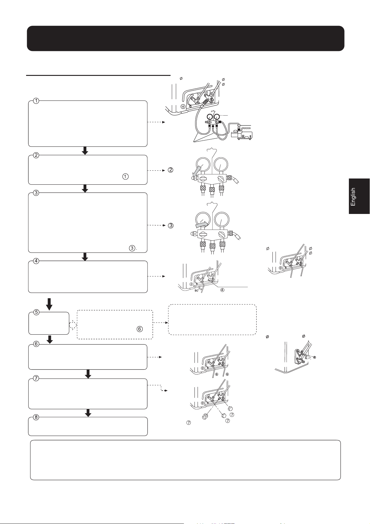
5.Purging Method:To use vacuum pump
Detach the service port's cap of 3-way valve, the
valve rod's cap for 2-way valve and 3-way's, connect
the service port into the projection of charge hose
(low) for gaugemanifold.Then connect the projection
of charge hose (center) for gaugemanifold into
vacuum pump.
Open the handle at low in gaugemanifold, operate
vacuum pump. If the scale-moves of gause (low)
reach vacuum condition in a moment, check again.
Vacuumize for over 15min. And check the level gauge
which should read -0.1 MPa (-76 cm Hg) at low
pressure side. After the completion of vacuumizing,
close the handle 'Lo' in gaugemanifold and stop the
operation of the vacuum pump.
Check the condition of the scale and hold it for 1-2min.
If the scale-moves back in spite of tightening, make
flaring work again, the return to the beginning of .
Open the valve rod for the 2-way valve to an angle of
anticlockwise 90 degrees.
After 6 seconds, close the 2-way valve and make
the inspection of gas leakage.
In case of gas leakage, tighten
No gas leakage?
parts of pipe connection. If
leakage stops, then proceed
steps.
2-way valve
Open
Close
2-way valve
If it does not stop gas leakage, discharge
whole refrigerants from the service port.
After flaring work again and vacuumize,
fill up prescribed refrigerant from the gas
cylinder
Liquid Side
6.35mm(1/4")
Tube(for R410A)
Open
90
o
Gas Side
9.52mm(3/8")
12.7mm(1/2")
3-way valve
Gaugemanifold(for R410A)
Vacuum pump(for R410A)
3-way valve
Service port
90ofor 6 sec.
Anti countercurrent joint
Liquid Side
6.35mm(1/4")
2-way valve
HSU-07HEA03/R2
HSU-09HEA03/R2
HSU-09HEA103/R2
HSU-12HEA03/R2
HSU-18HEA03/R2
Liquid Side
6.35mm(1/4")
Gas Side
9.52mm(3/8")
12.7mm(1/2")
3-way valve
Gas Side
12.7mm(1/2")
Detach the charge hose from the service port, open
2-way valve and 3-way. Turn the valve rod anticlockwise
until hitting lightly.
To prevent the gas leakage, turn the service port's
cap, the valve rod's cap for 2-way valve and 3-way's
a little more than the point where the torque increases
suddenly.
After attaching the each caps, check the gas leakage
around the caps.
CAUTION:
1.If the refrigerant of the air conditioner leaks, it is necessary to
discharge all the refrigerant. Vacuumize first, then charge the liquid
refrigerant into air conditioner according to the amount marked on
the name plate.
2-way valve
3-way valve
2-way valve
90
3-way valve
HSU-22HEA03/R2
2-way valve
Service port cap
2.Please do not let other cooling medium, except specified one (R410A),
or air enter into the cooling circulation system. Otherwise, there will be
abnormal high pressure in the system to make it crack and lead to
personal injuries.
3-way valve
Valve rod cap
Valve rod cap
6
Page 8
1.Power Source Installation
The power source must be exclusively used for air conditioner. (Over I0A)
In the case of installing an air conditioner in a moist place, please install an
earth leakage breaker.
For installation in other places, use a circuit breaker as far as possible.
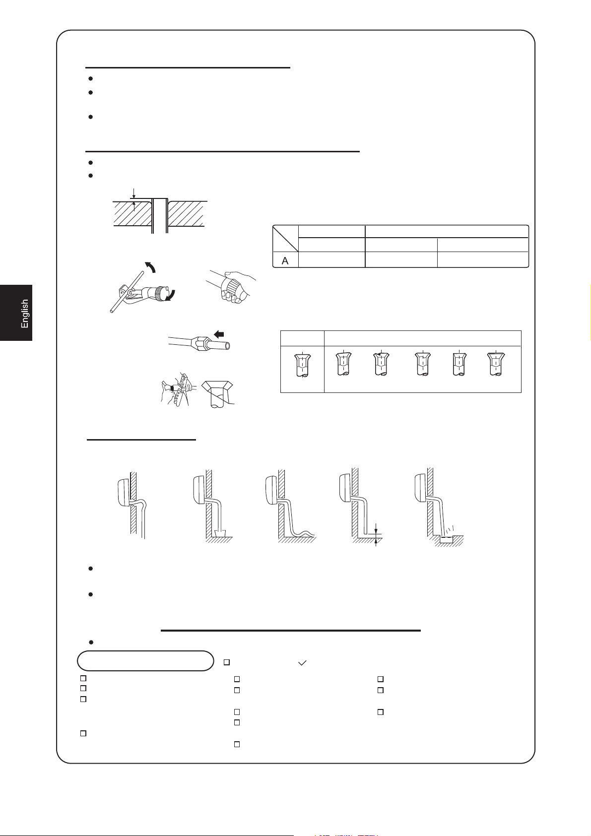
2.Cutting and Flaring Work of Piping
Pipe cutting is carried out with a pipe cutter and burs must be removed.
After inserting the flare nut, flaring work is carried out.
A
1.Cut pipe
Flare tooling die
2.Remove burs
Flare tool for R410A
Clutch-type
0~0.5mm 1.0~1.5mm 1.5~2.0mm
clutch-type(Rigid-type)
Conventional flare tool
3.Insert the flare nut
Correct
Incorrect
4.Flare pipe
Lean Damage of flare Crack Partial Too outside
3.On Drainage
Please install the drain hose so as to be downward slope without fail.
Please don't do the drainage as shown below.
Wing-nut type (Imperial-type)
Less than 5cm
It becomes high midway.
The end is immersed
in water.
It waves. The gap with the ground
is too small
There is the bad smell
from a ditch
Please pour water in the drain pan of the indoor unit, and confirm that drainage is
carried out surely to outdoor.
In case that the attached drain hose is in a room, please apply heat insulation
to it without fail.
Check for Installation and Test Run
Please kindly explain to our customers how to operate through the instruction manual.
Check Items for Test Run
Gas leak from pipe connecting?
Heat insulation of pipe connecting?
Are the connecting wirings of
indoor and outdoor firmly inserted
to the terminal block?
Is the connecting wiring of indoor
and outdoor firmly fixed?
Put check mark in boxes
Is drainage securely carried out?
Is the earth line securely
connected?
Is the indoor unit securely fixed?
Is power source voltage abided
by the code?
Is there any noise?
7
Is the lamp normally lighting?
Are cooling and heating (when
in heat pump) performed normally?
Is the operation of room temperature
regulator normal?
Page 9
Manual de instalación de aparato de aire acondicionado
Lea este manual antes de la instalación
Explique el uso del aparato al usuario siguiendo
las instrucciones de este manual.
Herramientas necesarias para realizar la instalación
1. Destornillador 5. Llave dinamométrica (17 mm, 22 mm, 26 mm) 9. Alicate 12. Avellanador
2. Sierra para metales 6. Cortador de tubo
3. Taladro 7. Llave para tuercas cónicas
4. Llave (17, 19 y 26 mm) 8. Cuchilla 11. Metro
Diagrama para la instalación de aparatos interiores y exteriors
10. Detector de fugas de gas o
solución de agua jabonosa
Accesorios
Nº
ķ
ĸ
Ĺ
ĺ
Ļ
ø 4X50
Clavo de acero, cemento
ļ
Tapón de plástico
Ľ
ľ
Ŀ
Placa de soporte del tubo
ŀ
Accesorio
Control remoto
Batería seca R-03
Placa de montaje
Manguera de drenaje
Tornillo ø4X25
Cubierta
Acolchado
Número
de
artículos
1
2
1
1
6
4
1
4
1
1
Componentes opcionales para la
instalación de los tubos
Marca
࿆
࿇
࿈
࿉
࿊
࿋
࿌
Organización de la dirección de los tubos
Izquierda
Nombre del
componente
Cinta no adhesiva
Cinta adhesiva
Soporte (L.S) con
tornillos
Conexión de
cable eléctrico
para interior y
exterior
Manguera de
drenaje
Material aislante
de calor
Cubierta de
orificio de
entubación
Izquierda trasera
Izquierda derecha
Derecha
Inferior
más de 10 cm
más de 5 cm
más de 10 cm
Il faut faire attention à la
remontée du tuyau de drainage
más de 10 cm
más de 10 cm
A
C
D
E
Codo de drenaje
Las marcas de la a la que se muestran
࿆
࿌
en la figura representan los componentes.
La distancia entre la unidad interior y el suelo debe
ser superior a 2 m.
más de
60 cm
más de 15 cm
8
Page 10
652
140
500 140
Dimensiones de fijación al suelo de la unidad
exterior
(Unidades: mm)
HSU-07HEA03/R2
HSU-09HEA03/R2
HSU-09HEA103/R2
HSU-12HEA03/R2
HSU-18HEA03/R2
Fijación de la unidad exterior
319.5
115
580
115
Dimensiones de fijación al suelo de la unidad
exterior
(Unidades: mm)
HSU-22HEA03/R2
Fije la unidad a un bloque de cemento con pernos (ø10 mm) y
tuercas firme y horizontalmente.
Si instala la unidad sobre una pared, techo o tejado, instale un
soporte con clavos o cables considerando la posibilidad de
terremotos o viento fuerte.
Si la vibración afectase a la casa, fije la unidad instalando una
alfombra de absorción de vibraciones.
Unidad interior
Coloque la unidad sobre una superficie que pueda soportarla
correctamente y no provoque vibraciones.
Asegúrese de que el lugar no se ve afectado por calor o vapor
o en las cercanías y donde la unidad pueda funcionar sin
generad
perturbaciones.
Asegúrese de que el lugar permita un drenaje sencillo y en el que
puedan conec
Asegúrese de que el aire frío pueda distribuirse uniformemente por la
.
sala
Coloque la unidad interior cerca de una toma de suministro eléctrico
con es
Coloque la unidad interior de modo se encuentre a más de 1 m de
te
levisiones, radios, a
En el caso de fijar el control remoto a una pared, colóquelo donde la
unidad
lám
paras fluorescentes de la sala.
tarse los tubos a la unidad exterior.
pacio suficiente alrededor. (Consulte los diagramas).
paratos inalámbricos y lámparas fluorescentes.
interior pueda recibir su señal mientras estén encendidas las
Selección del lugar de instalación
Seleccione el lugar menos afectado por la lluvia o la
luz solar directa y suficientemente ventilado.
Elija un lugar que permita soportar el peso de la
unidad y que no amplifique el ruido y las vibraciones.
Seleccione un lugar en el que los residuos y el viento
ge
nerado por la unidad no cause una molestia a los
vecinos.
Coloque la unidad en un lugar en el que pueda
dis
ponerse de la distancia de separación marcada
el símbolo
con
en la figura anterior.
Unidad exterior
Fuente de alimentación
Antes de insertar el enchufe de alimentación en la toma, compruebe que el voltaje no falla. La fuente de alimentación es la que figura
en la placa de datos nominales.
stale el aparato en un circuito dedicado de alimentación.In
Debe existir una toma al alcance del cable de alimentación. No prolongue el cable cortándolo.
Selección de tubo
En esta unidad los tubos de líquido y gas deben aislarse debido
a su baja temperatura de funcionamiento.
Utilice componentes opcionales para conjuntos de entubación o
tubos cubiertos con material de aislamiento equivalente.
Tubo de
líquido
Tubo de gas
(ø)
9
(ø)
Para 07 09 12 Para 18 22
mm (1/4")
mm (1/4")
6,35
mm (3/8") 12,7 mm (1/2")
9,52
6,35
Page 11
Unidad interior
Unidad interior
1. Instalar la placa de montaje y ubicar el orificio en la pared
Al fijar por primera vez la placa de montaje
1. Nivele correctamente la placa a fijar contra la pared basándose en pilares o dinteles cercanos y fije
temporalmente la placa con un clavo de acero.
2. Asegúrese de nuevo de que la placa se encuentre bien nivelada colgando una plomada desde el punto superior
central de la placa. Una vez comprobado, fije la placa con el clavo de acero de fijación.
3. Busque la ubicación del orificio de pared A utilizando un metro.
B= 60mm
A=145mm
30mm
Al montar la placa de montaje fijándola a una barra lateral y un dintel
y Fije una barra de montaje (se vende por separado) a la barra lateral y el dintel, y asegure la placa a la barra de
montaje fijada.
y Consulte la sección anterior " Al fijar por primera vez la placa de montaje " para más información
acerca del orificio de la pared.
2.Practicar un orificio en la pared e instalar la cubierta del orificio de entubación
pendiente ligeramente descendiente hacia el
exterior de la pared.
séllela con masilla después de la instalación.
3. Instalación de la unidad interior
Extracción de los tubos
z Practique un orificio de 60 mm de diámetro con
Cara interior Cara exterior
Orificio de pared de Grosor de la pared z Instale la cubierta del orificio de entubación y
60mm
(Sección del orificio de pared) ࿌ Orificio de entubación
[ Entubación trasera ]
z Extraiga los tubos y la manguera de drenaje y fíjelos con cinta adhesiva
[ Izquierda y Entubación trasera izquierda ]
z En caso de realizar la entubación por el lado izquierdo, corte con una cuchilla la cubierta de la entubación
izquierda.
z En caso de realizar la entubación a través de la parte trasera izquierda, doble los tubos de acuerdo con la
dirección de entubación que figura en la marca del orificio de entubación trasera izquierda, ubicada sobre
los materiales aislantes.
10
Page 12

Unidad interior
1 Pase la manguera aislante a través del hueco de los materiales de aislamiento de calor de la unidad interior.
2 Inserte los cables eléctricos de interior / exterior a través de la parte trasera de la unidad interior y tire de
ellos desde la parte delantera. Conéctelos entonces.
3 Cubra la cara de sellado con aceite refrigerante y conecte los tubos.
Cubra la conexión con material aislante de calor y asegúrese de fijarla con cinta adhesiva.
Cable eléctrico de interior/exterior
Cubierta de entubación derecha
Cubierta de entubación inferior
Fijación con cinta adhesiva
Material aislante de calor Entubación
Manguera de drenaje
Cubierta de entubación izquierda
Los cables eléctricos de interior/exterior deben conectarse a la entubación del refrigerante utilizando cinta protectora.
[Entubación en otra dirección]
Corte con una cuchilla la cubierta de entubación de acuerdo con la dirección de entubación y doble los tubos de
acuerdo con la posición del orificio en la pares. Tenga cuidado de no romper los tubos al doblarlos.
Conecte previamente el cable eléctrico de interior / exterior y tire de la conexión al aislante de calor del componente
de conexión.
Fijación de la unidad interior
Cuelgue con seguridad la unidad de las muescas
superiores de la placa de montaje. Mueva el bastidor
hacia los lados para verificar que la fijación se haya
realizado de la forma correcta.
Para fijar el bastidor a la placa de montaje, sostenga el
aislante del bastidor desde debajo y colóquelo en
posición perpendicular.
placa de montaje
Descarga de la unidad interior
Al descargar la unidad interior, utilice la mano para
levantar el bastidor y separarlo del gancho. Levante
entonces la parte inferior del bastidor llevándolo hacia
fuera ligeramente hasta que la unidad se separe de la
placa de montaje.
Desmontaje de la unidad interior para su limpieza
La rejilla de entrada se puede retirar
Abra
la rejilla de entrada, presione el botón de bloqueo
situado a la izquierda y presione a través de la ranura para
extraer la rejilla de entrada.
placa de montaje
gancho
11
Page 13

Unidad interior
Conexión de los cables eléctricos de interior/exterior
Extraer la cubierta del cableado
Extraiga la cubierta de los terminales situada en la esquina inferior derecha de la unidad
interior. Extraiga entonces la cubierta del cableado desenroscando los tornillos.
Al conectar el cable después de instalar la unidad de interior
1 Inserte desde fuera el cable en la sala a través del lado izquierdo del orificio de la pared en
el que ya se encuentra el tubo.
2 Tire del cable desde el lado delantero y conecte el cable creando un bucle.
Al conectar el cable antes de instalar la unidad de interior
Inserte el cable desde la parte trasera de la unidad y tire desde la parte delantera.
Afloje los tornillos e inserte los extremos del cable en el bloque de terminales. Apriete entonces los tornillos.
Tire ligeramente del cable para asegurarse de que los cables han quedado correctamente insertados y apretados.
Después de conectar el cable, no olvide fijar el cable conectado con la cubierta de cable.
Nota: Al conectar el cable, confirme el número de terminales de las unidades interior y exterior detenidamente. Si el
cableado no se ha realizado correctamente no se podrá utilizar el aparato correctamente, provocándose un defecto.
1 Si el cable de alimentación está dañado deberá ser reemplazado por el fabricante, agente de servicio o
profesional cualificado. El tipo de cable de conexión es H05/07RN-F o 245IEC57 (YZW).
2 Si el fusible de la placa PC está roto, cámbielo por otro de tipo T. 3,15ª / 250 V.
3 El método de cableado debe ajustarse a las normas de cableado locales.
4 Después de la instalación, la toma de alimentación debe ser accesible.
5 Debe instalarse un interruptor en el cableado fijo. La distancia entre los dos contactos del interruptor no debe
ser inferior a 3 mm.
Unidad
interior
Unidad
interior
HSU-22HEA03/R2
HSU-07HEA03/R2
HSU-09HEA
HSU-09HEA103/R2
HSU-12HEA03/R2
HSU-18HEA03/R2
03/R2
Unidad
exterior
21
3
4
5
L
N
3
4
Unidad
exterior
ALIMENTACIÓN
12
Cable de alimentación:
-mod 07-09-12:
-mod 18:
-mod 22:
cableado de conexión:
-mod 07-09-12:
-mod 18:
LǃNǃ :
3ǃ4:
LǃNǃ
3ǃ4:
-mod 22:
3G1.0mm
3G2.5mm
3G2.5mm
:
3G1.0mm
2X0.75mm
3G2.5mm
2X0.75mm
6G0.75mm
Page 14

Unidad exterior
1. Instalación de la unidad exterior
Instale la unidad exterior de acuerdo con el diagrama de instalación de unidades interiores y exteriores.
2. Conexión de los tubos
Para doblar un tubo, intente hacer la curva lo más suave posible para no aplastar el tubo. El radio de doblado debe ser
superior a 30 o 40 mm.
Será más sencillo conectar en primer lugar el tubo de gas.
El tubo de conexión es especial para el tipo R410A.
Media unión Tuerca cónica
Si se fuerza la fijación sin aplicar centrado podrían
dañarse los tubos y provocarse una fuga de gas.
Diámetro del tubo(ø) Par de apriete
Lado de líquido 6,35 mm
(1/4")
Lado de gas 9,52mm (3/8") 42N.m
Llave
Llave dinamométrica
Lado de gas 12,7mm (1/2") 55N.m
Procure que no penetren materiales, como residuos o arena, en el tubo.
La longitud estándar del tubo es de 5 m. Si el tubo tiene más de 7m, se verán afectadas las funciones de la unidad. Si es
necesario alargar el tubo, deberá cargarse refrigerante adicional a razón de 20 g / m. No obstante, la carga de
refrigerante deberá ser realizada por un ingeniero profesional en aire acondicionado. Antes de añadir refrigerante
adicional, realice una purga de aire desde los tubos refrigerantes y la unidad interior utilizando una bomba de vacío y
cargue después el refrigerante adicional.
18N.m
Unidad exterior
Unidad interior
B
A
B
Unidad interior
A
Unidad exterior
PRECAUCIÓN
Elevación máx.: A máx1 = 10 m Longitud máx.: B máx1 = 15 m
A máx2 = 15 m
En caso de que la elevación A sea superior a 5 m, el filtro de aceite
debe instalarse cada 5 ~ 7 m.
(07k 09k 12k)
(18k 22k)
En caso de que la longitud del tubo B sea
superior a 7 m, deberá cargarse el refrigerante
Unidad exterior
B
A
In case A is more than 5m
B máx
2 = 25 m
a razón de 20 g / m.
3. Conexión
Utilice el mismo método con la unidad interior.
Afloje los tornillos del bloque de terminales e
inserte los tapones completamente en los
mismos. Apriete entonces los tornillos.
Inserte el cable de acuerdo con el número del
terminal, de la misma forma que hizo con la
unidad interior.
Si el cableado no es correcto, no podrá
alcanzarse la orientación correcta y el controlador
podría resultar dañado.
Fije el cable con un alicate.
4. Instalación del codo de drenaje
Filtro de aceite
Unidad interior
(07k 09k 12k)
(18k 22k)
Si utiliza un codo de drenaje, instálelo como indica la figura.
Nota: sólo para la unidad de bomba de calor.
13
Manguera de
drenaje
Codo de drenaje
Page 15

Unidad exterior
5. Método de purga: para utilizar una
bomba de vacío
Válvula de 2 vías
Retire el tapón del puerto de mantenimiento de la
válvula de 3 vías (G), el tapón del vástago de la
válvula de 2 vías (L) y las 3 vías (G), y conecte el
puerto de mantenimiento a la manguera de
proyección de carga (inferior) del colector. Conecte
entonces la manguera de proyección de carga
(central) del colector a la bomba de vacío.
Abra la espita inferior del colector y accione la
bomba de vacío. Si el indicador de la escala
(inferior) alcanza la condición de vacío por un
momento, compruebe de nuevo el punto
Succione durante 15 minutos. Compruebe el
nivel medido, que deberá ser de -0,1 Mpa (-76
cm Hg) en el lado de baja presión. Tras finaliza
la succión, cierre la espita inferior del colector y
detenga la bomba de vacío.
Compruebe el funcionamiento de las escala y
manténgala durante 1-2 min. Si la escala
retrocede en lugar de aumentar, aplique de
nuevo el ensanche y vuelva al punto (3).
Abra el vástago de la válvula de 2 vías 90
grados hacia la izquierda.
Después de 6 segundos, cierre la válvula de 2
vías e inspeccione si existen fugas de gas.
¿No existen
fugas de gas?
En caso de que exista una fuga de
gas, apriete las conexiones de los
tubos. Si la fuga se detiene,
avance
6
1
r
Válvula de 2 vías
pasos.
Lado de líquido
6, 35 mm (1/4")
Tubo (para R410A)
Lado de gas
9,52mm (3/8")
12,7mm (1/2")
Válvula de 3 vías
Colector (para R410A)
Bomba de vacío(para R410A)
Abrir
Cerrar
Válvula de 3 vías
Puerto de mantenimiento
Abrir
o
90
Si la fuga de gas no se detiene,
descargue todo el refrigerante a través
del puerto de mantenimiento. Después
de realizar de nuevo la operación de
conicidad y succión, rellene con el
refrigerante especificado desde el
cilindro de gas.
o
90 durante 6 seg.
Junta de retención de contracorriente
Lado de líquido
6,35mm (1/4")
Válvula de 2 vías
Válvula de 3 vías
HSU-07HEA03/R2
HSU-09HEA03/R2
HSU-09HEA103/R2
HSU-12HEA03/R2
HSU-18HEA03/R2
Lado de líquido
6,35mm (1/4")
Lado de gas
Lado de gas
9,52mm (3/8")
12,7mm (1/2")
12,7mm (1/2")
Desconecte la manguera de carga del puerto
de mantenimiento y abra las válvulas de 2 y 3
vías. Gire el vástago de la válvula hacia la
izquierda hasta que golpee ligeramente.
Para evitar fugas de gas, gire el tapón del
puerto de mantenimiento y el tapón del vástago
de las válvulas de 2 y 3 vías un poco por
encima del punto en el que la torsión aumenta
súbitamente.
Después de instalar los tapones, compruebe si
existen fugas de gas a su alrededor.
PRECAUCIÓN:
1. Si existen fugas de refrigerante en el aire acondicionado
será necesario descargar todo el refrigerante. Succione
primero, y cargue líquido refrigerante en el acondicionador de
aire de acuerdo con la cantidad marcada en la placa de valores
nominales.
Válvula de 2 vías
Válvula de 3 vías
Válvula de 2 vías
HSU-22HEA03/R2
Válvula de 2 vías
Tapa del puerto de
mantenimiento
2. Por favor, no permita que penetren otros medios de refrigeración
(excepto el especificado, R410A) o aire en el sistema de circulación del
refrigerante. Si ocurriese, se acumularía una presión anormalmente
alta en el sistema que podría provocar roturas y lesiones personales.
Válvula de 3 vías
Tapa del vástago de válvula
Tapa del vástago de válvula
14
90
Válvula de 3 vías
Page 16

1. Instalación de la fuente de alimentación
La fuente de alimentación debe utilizarse exclusivamente con el aparato de aire acondicionado. (Más de
10 A)
En caso de instalar el aire acondicionado en un lugar húmedo, instale un interruptor de fugas de masa.
Para realizar la instalación en otro lugar, utilice un interruptor de circuito situado lo más lejos posible.
2. Trabajos de corte y conicidad de los tubos
El corte del tubo se realiza con un cortador de tubos. Deberán eliminarse las rebabas.
Después de insertar la tuerca cónica deberá procederse a realizar los trabajos de conicidad.
A
Herramienta de
conicidad para
Cuchilla de conicidad
1. Cortar el tubo 2. Eliminar las
rebabas
R410A
De tipo
acoplamiento
A 0~0,5 mm 1,0~1,5 mm 1,5~2,0 mm
3. Insertar la tuerca cónica
4. Practicar la conicidad del tubo
Correcto Incorrecto
DelgadoDaño de conicidad Grieta Parcial Demasiado fuera
3. Durante el drenaje
Instale la manguera de drenaje formando una pendiente descendiente.
No realice el drenaje como se muestra a continuación.
Herramienta de conicidad
convencional
De tipo
acoplamiento
(tipo rígido)
De tipo palometa
(tipo imperial)
Menos de 5 cm
Se alza por la mitad.
El extremo está
sumergido en agua.
Está ondulado.
La separación con el suelo
es demasiado pequeña
Se aprecia mal olor de
una acequia
Deposite agua en la bandeja de drenaje de la unidad interior y confirme que el drenaje se realiza
correctamente hacia fuera.
En caso de que la manguera de drenaje se encuentre en una sala, asegúrese de aplicar aislante de calor.
Prueba de instalación y ejecución de la prueba
Explique al cliente cómo utilizar el aparato utilizando el manual de instrucciones.
Puntos de prueba
¿Existe una fuga de gas en la
conexión del tubo?
¿Aislamiento de calor de la
conexión del tubo?
¿Están los cables de conexión
interiores y exteriores firmemente
insertados en el bloque de
terminales?
¿Están los cables de conexión
interior y exterior fijados
firmemente?
Escriba una marca √ en los cuadros
¿Se ha realizado el drenaje
correctamente?
¿Está la línea de tierra conectada
con seguridad?
¿Está la unidad interior fijada con
seguridad?
¿Cumple la normativa la fuente de
voltaje?
¿Se aprecian ruidos?
¿Está la lámpara iluminada
normalmente?
¿Se realizan normalmente las
operaciones de calentamiento (con
la bomba de calor) y refrigeración?
¿Funciona correctamente el
regulador de temperatura de la
sala?
15
Page 17

Manuale di installazione per condizionatore ad aria per ambienti
Prima dell'installazione leggere questo manuale
Spiegare in modo sufficiente il funzionamento
dell'apparecchio all'utente in base a quanto indicato
in questo manuale.
Attrezzi necessari per l'installazione
1.Cacciavite 5.Chiave dinamometrica (17mm, 22mm, 26mm) 9.Pinza 12.Alesatore
2.Seghetto a mano 6.Taglia tubi
3.Trapano alesatore 7.Flangiatubi
4.Chiave fissa (17,19 e 26mm) 8.Coltello 11.Nastro di misurazione
Disegno per l'installazione dell'elemento interno e di quello esterno
Accessori
N.
ķ
Accessori
Telecomando
Numero
di articoli
1
10.Rilevatore di perdite di gas o
soluzione di acqua saponata
ĸ
Batteria secca R-03
Ĺ
Piastra di montaggio
ĺ
Tubo di scarico
Ļ
Chiodo in acciaio ø 4X50,
cemento
ļ
Vite ø4X25, Calotta in
plastica
Ľ
Copertura
ľ
Cuscinetto
Ŀ
Piastra di sostegno tubo
ŀ
2
Componenti opzionali per le tubature
1
1
6
4
1
4
1
1
Contrassegno
࿆
࿇
࿈
࿉
࿊
࿋
࿌
Disposizione del tracciato dei tubi
Sinistra posteriore
Sinistra
Nome
componente
Nastro non
adesivo
Nastro adesivo
Carrello (L.S) con
viti
Cavo elettrico di
connessione per
elemento interno
ed esterno
Tubo di scarico
Materiale isolante
per riscaldamento
Tappo per foro
per tubi
Sinistra destra
Destra
Sotto
più di 10 cm
più di 5 cm
più di
1
0 cm
Bisogna prestare attenzione
più di
all’ innalzamento del
tubo di scarico
1
0 cm
A
C
più di 10 cm
D
E
Raccordo di scarico
I contrassegni da a nella figura indicano i
࿆
࿌
numeri dei componenti
La distanza tra l'elemento interno e il pavimento
dovrebbe essere superiore a 2 m.
16
più di 60
cm
più di 15 cm
Page 18
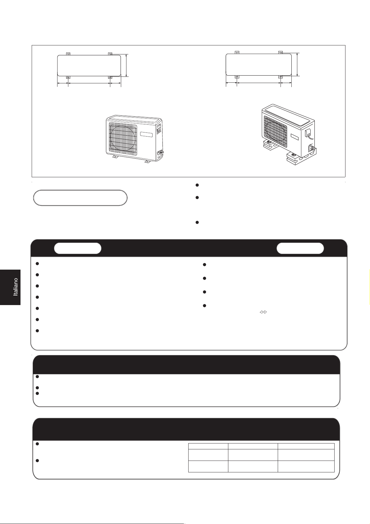
140
50
0 140
652
319.5
115
580
115
Dimensioni per il fissaggio al suolo
dell'elemento esterno
(Unità:mm)
HSU-07HEA03/R2
HSU-09HEA03/R2
HSU-09HEA103/R2
HSU-12HEA03/R2
HSU-18HEA03/R2
Fissaggio dell'elemento esterno
Componente interno
Luogo resistente, che non sia fonte di vibrazioni, dove il corpo
dell'ap
parecchio possa essere sostenuto a sufficienza.
Luogo non interessato dal calore o dal vapore generato nelle
vicinanze, in
Luogo in cui sia semplice effettuare lo scarico, dove i tubi possano
essere collegati
Luogo in cui l'aria fredda possa diffondersi completamente nella
stanza.
Luogo accanto a una presa di corrente, contornato da spazio
sufficiente. (Fare riferimento ai disegni).
Luogo in cui si possa lasciare una distanza superiore a 1 m da
te
levisori, radio, apparecchi senza fili e lampade al neon.
Nel caso di sospensione del telecomando a parete, metterlo dove
l'elemento interno può ricevere segnali quando nella stanza sono
accese delle la
cui l'ingresso e l'uscita dell'unità non siano disturbati.
con l'elemento esterno.
mpade al neon.
Scelta del luogo di installazione
Dimensioni per il fissaggio al suolo
dell'elemento esterno
(Unità:mm)
HSU-22HEA03/R2
Fissare l'unità al calcestruzzo o al blocco mediante bulloni
(ø10 mm) e dadi, in modo saldo e in senso orizzontale.
Collegando l'unità alla superficie di una parete, al tetto o sulla
sommità di un tetto, fissare in modo sicuro un sostegno
mediante chiodi o cavi, tenendo in considerazione possibili
scosse sismiche o venti forti.
Se l’edificio può essere interessato da vibrazioni, fissare
l'elemento collegando una platea di fondazione anti-vibrazioni.
Componente esterno
Il luogo meno interessato dalla pioggia o dalla luce
retta del sole e che sia sufficientemente ventilato.
di
Luogo in grado di sostenere l'elemento, senza
aumento di vibrazioni e rumorosità.
Luogo in cui il flusso d'aria rilasciato e il rumore
prodotto non causino disturbo ai vicini.
Luogo in cui sia disponibile una distanza
contrass
egnata da
, come illustrato nella figura
sopra riportata.
Alimentazione
Prima di inserire la spina nella presa, controllare con precisione la tensione consentita. La sorgente di alimentazione è quella riportata
sulla piastra con il nome corrispondente.
stallare un circuito di derivazione esclusivo per l'alimentazione. In
Bisogna inserire una presa a una distanza tale per cui possa essere raggiunta con il cavo di alimentazione. Non prolungare il cavo
tagliandolo.
Scelta del tuboe
Con questa unità, tanto i tubi per i liquidi quanto quelli per i gas
devono essere isolati in quando scendono a basse temperature
durante il funzionamento.
Usare elementi opzionali per serie di tubi o tubi coperti con
materiale isolante equivalente.
Tubo per
liquidi (ø)
Tubo per gas
(ø)
17
07 09 12 Per 18 22
Per
6,35
mm (1/4") 6,35 mm (1/4")
9,52
mm (3/8") 12,7 mm (1/2")
Page 19

Componente interno
Componente interno
1.Inserimento della piastra di montaggio e posizionamento del foro sulla parete
Quando si fissa prima la piastra di montaggio
1. Basandosi sui pilastri o sulle architravi vicini, effettuare un livellamento corretto, in modo che la piastra possa
essere fissata al muro, poi fissare in modo provvisorio la piastra con un chiodo in acciaio.
2. Accertarsi nuovamente che il livello a cui è fissata la piastra sia corretto, sospendendo un filo a piombo dal centro
della sommità della piastra, poi fissare saldamente la piastra con il chiodo in acciaio destinato ad attaccarla.
3. Individuare il punto di posizionamento del foro A sulla parete utilizzando un nastro di misurazione
B= 60mm
A=145mm
30mm
Quando la piastra di montaggio è fissata su una trave laterale o su un'architrave
y Fissare una barra di sostegno, venduta separatamente, alla trave laterale e all'architrave e poi fissare la piastra alla
barra di sostegno precedentemente fissata.
y Per il posizionamento del foro sulla parete, fare riferimento al punto precedente, " Quando si fissa prima la
piastra di montaggio
" .
2.Ricavare un foro sulla parete e inserire il tappo per i fori delle tubature
z Ricavare un foro del diametro di 60 mm,
scendendo leggermente fuori dalla parete.
z Inserire il coperchio per i fori dei tubi e stuccarlo
dopo l'installazione
Lato interno Lato esterno
60mm
(Sezione del foro a parete) ࿌ G Tubo per foro per tubature
Foro a parete Spessore del muro
3.Installazione dell'elemento interno
Disegno del tubo
[ Vista posteriore del tubo ]
z Tracciare i tubi e il tubo di scarico, poi fissarli con il nastro adesivo
Sinistro y vista posteriore della tubatura posta sulla sinistra ]
[
z In caso di tubazioni inserite sul lato sinistro, asportare con l'ausilio di una pinza, il coperchio per le tubazioni
del lato sinistro.
z In caso si abbiano tubi posti sul lato posteriore sinistro, piegare i tubi secondo la direzione delle condutture
indicata dal contrassegno sul foro per tubi posti sul lato posteriore sinistro che è marcato sui materiali
termoisolanti.
18
Page 20

Componente interno
1 Inserire il tubo di scarico nella tacca presente sui materiali termoisolanti dell'elemento interno.
2 Inserire i cavi elettrici per interni/esterni dal retro dell'elemento interno e tirarli fuori dal lato frontale, poi
effettuare il loro collegamento.
3 Ricoprire con uno strato di
Copri
re bene l'elemento di connessione con materiali termoisolanti e fissarli saldamente con nastro adesivo
olio refrigerante la facciata con il dispositivo di tenuta svasato e collegare i tubi.
Tubature
Cavi elettrici interni/esterni
Coperchio per le tubature
poste sulla destra
Coperchio per le tubature
poste sul lato inferiore
Fissaggi con nastro adesivo
Cope
rchio per le tubature poste sulla sinistra
Materiale termoisolante
Tubo di scarico
I cavi elettrici interni/esterni e il tubo di scarico devono essere legati ai tubi contenenti il liquido refrigerante con nastro
di protezione.
[Tubature con altre direzioni]
Asportare, con una pinza, il coperchio per le tubature secondo la direzione delle tubature e poi piegare i tubi secondo
la posizione del foro sul muro. Effettuando la piegatura fare attenzione a non danneggiare i tubi.
Collegare in primo luogo i cavi elettrici interni/esterni e poi estrarre quello connesso specificatamente al
termoisolamento dell'elemento di connessione.
Fissaggio del corpo dell'elemento interno
Sospendere in modo sicuro il corpo dell'elemento
fissandolo alle tacche superiori presenti sulla piastra di
montaggio. Spostare il corpo dell'elemento da lato a lato
per verificare che sia fissato in modo sicuro.
Per fissare il corpo sulla piastra di montaggio, sostenere
il
corpo obliquamente dal basso e poi posarlo
perpendicolarmente.
piastra di montaggio
Asportare e abbassare il corpo dell'elemento esterno
Nell'asportare e abbassare il corpo dell'elemento
esterno, usare le mani per sollevare il corpo in modo
che si svincoli dal gancio che lo trattiene, sollevare poi il
fondo
del corpo spingendolo leggermente verso
l'esterno e poi sollevare trasversalmente l'elemento fino
a che non esce dalla piastra di montaggio.
Smontare facilmente l'elemento interno per poterne effettuare la pulizia
La griglia di immissione può essere rimossa
Aprire
la griglia di immissione, premere il pulsante di
sblocco sulla sinistra, poi spingere la griglia di immissione
fuori dalla sua sede e rimuoverla.
19
gan
piastra di montaggio
cio
Page 21

Componente interno
Collegamento del cavo elettrico per interni/esterni
Asportazione della copertura dei fili elettrici
Togliere la copertura dei morsetti posta sull'angolo inferiore destro dell'elemento interno, poi
asportare la copertura dei fili elettrici togliendone le viti.
Quando si collega il cavo dopo aver inserito l'elemento interno
1 Inserire dall'esterno il cavo destinato alla stanza nel lato sinistro del foro sulla parete, in cui il
tubo esisteva già.
2 Estrarre il cavo sul lato anteriore e collegarlo creando un circuito.
Quando si collega il cavo prima di aver installato l'elemento interno
Inserire il cavo dal retro dell'unità, poi estrarlo sul lato anteriore.
Allentare le viti e inserire completamente le estremità del cavo nella morsettiera, poi serrare le viti.
Tirare leggermente il cavo per accertarsi che sia stato inserito e serrato correttamente.
Dopo aver effettuato la connessione dei cavi, non trascurare mai di coprire il cavo collegato con la copertura di
protezione dei fili elettrici.
Nota: Quando si connette il cavo, verificare con attenzione il numero dei morsetti collegati all'elemento interno e a
quello esterno. Se il cablaggio non è corretto non si potrà avere un funzionamento corretto e ciò provocherà dei guasti.
1 Se il cavo di alimentazione è danneggiato, deve essere sostituito dalla casa produttrice o dal suo agente
responsabile per l'assistenza o da altro soggetto con qualifica analoga. Il tipo di cavo di connessione da
utilizzare è: H05/07RN-F o 245IEC57(YZW).
2 Se il fusibile sul circuito PC è rotto, sostituirlo con il tipo T. 3,15A/ 250V.
3 Il metodo di cablaggio utilizzato dovrebbe essere conforme con gli standard di cablaggio adottati a livello
locale.
4 Dopo l'installazione deve essere facile raggiungere la spina della corrente.
5 Nel cablaggio fisso dovrebbe essere inserito un interruttore di circuito. L'interruttore dovrebbe essere
omnipolare e la distanza tra i suoi due contatti dovrebbe essere non inferiore a 3mm.
Componente
rno
inte
Componente
interno
HSU-07HEA03/R2
HSU-09HEA
HSU-09HEA10
HSU-12HEA03/R2
HSU-18HEA03/R2
HSU-22HEA03/R2
03/R2
3/R2
21
3
4
5
L
N
Componente
esterno
3
4
Componente
esterno
ALIMENTAZIONE
20
Câble d'alimentation :
-mod 07-09-12:
-mod 18:
-mod 22:
branchement du câblage:
-mod 07-09-12:
-mod 18:
3G1.0mm
3G2.5mm
3G2.5mm
LǃNǃ :
3ǃ4:
LǃNǃ
3ǃ4:
-mod 22:
:
3G1.0mm
2X0.75mm
3G2.5mm
2X0.75mm
6G0.75mm
Page 22

Componente esterno
1.Installazione del componente esterno
Procedere all'installazione secondo il Disegno per l'installazione dell'elemento interno e di quello esterno
2.Collegamento dei tubi
Per piegare un tubo, conferire la massima rotondità possibile in modo da non danneggiare il tubo, il raggio di curvatura
dovrebbe essere di 30-40 mm o maggiore.
Collegare prima il tubo del lato del gas rende il lavoro più semplice.
Il tubo di connessione è particolarmente adatto per il refrigerante R410A.
unione parziale
dado svasato
Un fissaggio forzato, privo di attenta centratura può
provocare danni ai fili e causare una perdita di gas.
diametro del tubo(ø) coppia di serraggio
Lato del liquido 6,35 mm
18N.m
(1/4")
Lato del gas 9,52mm (3/8") 42N.m
Chiave fissa
Chiave dinamometrica
Lato del gas 12,7mm (1/2") 55N.m
Fare attenzione che materiali, come detriti di sabbia ecc., non penetrino nel tubo.
La lunghezza standard del tubo è di 5 m. Se esso supera i 7 m di lunghezza, il funzionamento dell'apparecchio potrebbe
risentirne. Se è necessario allungare il tubo, bisognerebbe aggiungere refrigerante secondo un rapporto di 20 g/m.
L'aggiunta di liquido refrigerante, tuttavia, deve essere effettuata da un tecnico esperto specializzato in condizionatori.
Prima di aggiungere ulteriore liquido refrigerante, effettuare uno spurgo dell'aria dai tubi del refrigerante e dall'elemento
interno con l'ausilio di una pompa per vuoto, poi aggiungere refrigerante aggiuntivo.
Componente esterno
Componente interno
B
A
Componente esterno
A
B
Componente interno
Componente esterno
A
B
Sifone per l'olio
Componente interno
ATTENZIONE
Elevazione massima: Amax1=10m
Amax
2=15m
(07k 09k 12k)
(18k 22k)
Nel caso in cui l'elevazione di A superii5m,ogni 5~7m dovrebbe
essere installato un sifone per l'olio
3.Connessione
Usare lo stesso metodo per l'elemento interno.
Allentare le viti sulla morsettiera e inserire
completamente le spine nella morsettiera, poi
un funzionamento corretto e ciò provocherà dei
guasti al circuito di controllo.
serrare le viti.
Inserire il cavo in base al numero di morsetto,
nello stesso modo adottato per l'elemento interno.
4. Collegamento del raccordo di scarico
Se si utilizza un raccordo di scarico, si prega di collegarlo
come nella figura.
Nota: Solo per la pompa termica.
In case A is more than 5m
Lunghezza massima: Bmax1=15m
Bmax
Nel caso in cui la lunghezza del tubo B sia
superiore a 7 m, dovrebbe essere addizionato
refrigerante, secondo un rapporto di 20 g/m.
Se il cablaggio non è corretto non si potrà avere
Fissare il cavo con un gancio.
Raccordo di scarico
(07k 09k 12k)
2=25m
(18k 22k)
Tubo di scarico
21
Page 23

Componente esterno
5.Metodo per eseguire lo spurgo: utilizzare
una pompa per il vuoto
Staccare il tappo della valvola a 3 uscite (G) della porta di
servizio, la calotta di protezione dell'asta delle valvole a 2
uscite (L) e (G), collegare la porta di servizio al
prolungamento del tubo di scarico (basso) per il manometro.
Collegare poi il prolungamento del tubo di scarico (centro) per
il manometro alla pompa per il vuoto.
Aprire
la manopola posizionata in basso sul manometro, far
funzionare la pompa per il vuoto. Se l'indicatore del
manometro (basso) raggiunge la condizione di vuoto in un
istante, controllare nuovamente quanto esposto al punto ķ
A spirare sottovuoto per più di 15min. Verificare il
lilvello del manomentro, la lettura deve essere di
-0.1 MPa (-76 cm Hg) sul lato a bassa
pressione. Dopo aver completato l'operazione,
chiudere la manopola "Lo" (Bassa) del raccordo
del manometro e fermare la pompa del vuoto.
Controlla le condizioni della scala graduata e
tenerla per 1-2min. Se la scala torna indietro
ripetere l'operazione di svasatura e tornare
all'inizio di (3).
A prire il rubinetto della vavola a 2 vie per 90°
gradi in senso antiorario.
Dopo 6 secondi, chiudere la valvola a 2 vie e
ripetere l'ispezione per verificare la presenza di
perdite di gas.
In
Non
ci sono
fuoriuscite di
gas?
Staccare il tubo della ricarica dall'apertura di servizio,
aprire la valvola a 2 vie e e quella a vie. Ruotare il
rubinetto della valvola in senso antiorario fino a serrarlo
leggermente.
caso si riscontrino fuoriuscite di gas,
stringere i raccordi del tubo. Se la
fuoriuscita cessa, procedere con le
operazioni descritte al punto
.
Valvola a 2 vie
Valvola a 2 vie
Se ciò non arresta la fuoriuscita di gas, far uscire
tutto il refrigerante dalla porta di servizio. Dopo aver
effettuato nuovamente lo spurgo e creato
nuo
refrigerante prescritta traendola dal cilindro del gas
Valvola a 2 vie
Lato liquido
6,35mm(1/4")
Tubo (per R410A)
lato gas
9,52mm(3/8")
12,7mm(1/2")
Valvola a 3 vie
Pompa del vuoto (per R410A)
Apre
Chiude
Valvola a 3 vie
Porta di servizio
Apre
o
90
vamente il vuoto, inserire la quantità di
o
per 6 sec.
90
Valvola a 3 vie
Collettore manometro (per R410A)
Giunzione per evitare il ritorno
Lato liquido Lato gas
6,35mm(1/4")
Valvola a 2 vie
HSU-07HEA03/R2
HSU-09HEA03/R2
HSU-09HEA103/R2
HSU-12HEA03/R2
HSU-18HEA03/R2
Lato liquido
6,35mm(1/4")
Valvola a 2 vie
9,52mm(3/8")
12,7mm(1/2")
Valvola a 3 vie
Lato gas
12,7mm(1/2")
90
Valvola a 3 vie
Per evitare le perdite di gas, ruotare il tappo del
rubinetto della valvola a 2 vie e di quello della valvola a
3 vie un po' oltre il punto di serraggio, in cui la
resistenza aumenta immediatamente.
aver collegato ciascuna calotta, controllare se vi siano
Dopo
fuoriuscite di gas attorno ad esse.
ATTENZIONE:
1.Se ci sono perdite di liquido refrigerante del condizionatore, è necessario
far uscire tutto il liquido refrigerante. Creare prima il vuoto, successivamente
caricare il liquido refrigerante nel condizionatore nella quantità
contrassegnata sulla targa riportante il nome.
HSU-22HEA03/R2
Valvola a 2 vie
Tappo porta di
servizio
Non introdurre altro tipo di refrigerante, diverso da quello specificato (R410A), e non
2.
lasciar penetrare aria nell'impianto di circolazione del refrigerante. Altrimenti, nel sistema
si produrrà un'alta pressione anomala, che ne provocherà la rottura e causerà lesioni alla
persona.
Valvola a 3 vie
Tappo rubinetto valvola
Tappo rubinetto valvola
22
Page 24

1.Installazione della sorgente di alimentazione
La sorgente di alimentazione deve essere utilizzata esclusivamente per il condizionatore. (Più di 10A)
Se si installa un condizionatore in un luogo umido, installare un interruttore di perdita della terra.
Per installazioni in altre sedi, usare il più possibile un interruttore di circuito.
2. Taglio e svasatura dei tubi
Il taglio dei tubi viene eseguito con un taglia tubi e le sbavature devono essere eliminate.
Dopo aver inserito un dado svasato si effettua la svasatura.
A
Stampo per la svasatura
1.Tagliare il tubo 2. Eliminare le
sbavature
3. Inserire il dado svasato
4. Effettuare la svasatura del tubo
3.Informazioni relativamente allo scarico
Installare il tubo di scarico in modo che abbia l'inclinazione verso il basso, senza commettere errori.
Non effettuare il drenaggio come sotto indicato.
Flangiatubi per
R410A
Tipo frizione Tipo frizione
A 0~0,5mm 1,0~1,5mm 1,5~2,0mm
Corretto Non corretto
Inclinato Svasatura danneggiata Parziale Troppo in fuori
Flangiatubi tradizionale
(tipo rigido)
Rottura
Tipo a galletto
(sistema imperiale)
Meno di 5 cm
Si solleva a metà percorso. L'estremità rimane
immersa nell'acqua.
La distanza dal suolo è
Ondeggia.
troppo ridotta
Il canale di scolo emette
un cattivo odore
Versare acqua nella vaschetta di raccolta condensa dell'elemento interno e accertarsi che il drenaggio
all'esterno abbia effettivamente avuto luogo.
Nel caso in cui il tubo di scarico si trovi in una stanza, applicare senza indugio ad esso l'isolamento termico.
Controllo dell'installazione e test di funzionamento
Spiegare ai clienti come far funzionare l'apparecchio, facendo riferimento al manuale di istruzioni.
Elementi da controllare effettuando
una prova di funzionamento
Perdita di gas dai collegamenti dei
tubi?
I collegamenti dei tubi sono dotati di
isolamento termico?
I cavi di connessione dell'elemento
interno e di quello esterno sono
saldamente inseriti nella
morsettiera?
Il cablaggio di connessione interno
ed esterno è fissato saldamente?
Inserire il segno di spunta √ nelle
caselle
Il drenaggio è stato eseguito in
modo sicuro?
La linea della terra è stata collegata
senza alcun dubbio?
L'elemento interno è fissato in modo
sicuro?
La tensione della sorgente di
alimentazione è conforme al
codice?
Si avvertono rumori?
La lampada si accende in modo
normale?
La refrigerazione e il riscaldamento
(quando è in funzione una pompa
termica) vengono svolti in modo
normale?
Il funzionamento del dispositivo di
regolazione della temperatura nella
stanza è normale?
23
Page 25

Manuel d'installation du climatiseur de pièce
Lisez ce manuel avant installation
Expliquez suffisamment le mode d'emploi à
l'utilisateur, dans le respect du présent manuel.
Outils nécessaires à l'installation
1.Tournevis 5.Clé dynamométrique (17mm, 22mm, 26mm) 9.Pince 12.Alésoir
2.Scie à métaux 6. Coupe-tuyau
3. Perceuse à prélever des
carottes
7. Outil à évaser
4. Clé (17, 19 et 26mm) 8.Couteau
10. Détecteur de fuite de gaz ou
solution d'eau savonneuse
11. Mètre ruban
Pièces accessoires
No.
ķ
ĸ
Pièces accessoires
Télécommande
Batterie sèche R-03
Ĺ
Plaque de fixation
ĺ
Tuyau de vidange
Ļ
ø 4X50
Clou en acier, pour béton
ļ
Vis ø4X25 Bouchon en
plastique
Ľ
ľ
Couvercle
Coussin
Nombre
d'articles
1
2
1
1
6
4
1
4
Dessins d'installation des unités intérieure et extérieure
plus de
Pièces optionnelles pour la tuyauterie
Repère Nom des pièces
࿆
࿇
࿈
࿉
࿊
࿋
࿌
Ruban non
adhésif
Ruban adhésif
Semelle (L.S)
avec vis
Câble de
branchement
électrique pour
l'intérieur et
l'extérieur
Tuyau de vidange
Matériau
d'isolation
calorifique
Capot de trou de
tuyau
10cm
plus de 5cm
plus de
10cm
Il faut
faire attention
remontée du tuyau de drainage
à la
plus de 10cm
plus de 10cm
A
C
Ŀ
Plaque de fixation du tuyau
ŀ
Coude de drainage
1
1
Disposition des sens de tuyaux
Arrière gauche
Gauche Gauche
Dessous
Les repères de ࿆ à࿌ sur la figure sont des références de
pièces.
La distance entre l'unité intérieure et le sol doit être supérieure à
2m.
Droite
24
D
E
plus de 15cm
plus de 60cm
Page 26

140
50
0 140
65
2
115
580
319.5
115
Dimensions de fixation au sol de l'unité
extérieure (Unité: mm)
HSU-07HEA03/R2
HSU-09HEA03/R2
HSU-09HEA103/R2
HSU-12HEA03/R2
HSU-18HEA03/R2
Fixation de l'unité extérieure
Unité intérieure
Endroit robuste n'entraînant pas de vibration, où le corps peut être
soutenu efficacement.
Endroit non soumis à de la chaleur ni à de la vapeur produite
alentours,
pertur
Endroit où une vidange rapide est possible, où la tuyauterie peut être
raccordée
Endroit où l'air frais peut être répandu intégralement dans la pièce.
Endroit proche d'une prise secteur, avec assez d'espace autour.
(Référez-vous aux dessins).
Endroit situé à une distance de plus de lm de toute télévision, radio ;
le
En cas de fixation de la télécommande sur un mur, placez là à un
endroi
éclairages fluorescen
et où l'entrée et la sortie de l'appareil ne sont pas
bées.
à l'unité extérieure.
pareils sans fil et les lampes fluorescentes peuvent rester.
s ap
t où l'unité intérieure peut recevoir les signaux lorsque les
ts de la pièce sont allumés.
Choix du lieu d'installation
Dimensions de fixation au sol de l'unité
extérieure (Unité: mm)
HSU-22HEA03/R2
Fixez l'unité sur du ciment ou des dalles à l'aide de boulons
(10mm) et d'écrous, fermement et horizontalement.
Lorsque vous montez l'unité sur une surface murale, un toit ou
un dessus de toit, fixez un support de façon sûre à l'aide de
clous ou de fils, pour prendre en considération un tremblement
de terre et un vent violent.
Si la maison est soumise à des vibrations, fixez l'unité en
attachant un mât à l'épreuve des vibrations.
Unité extérieure
Endroit peu affecté par la pluie ou la lumière directe du
soleil, et suffisamment ventilé.
Endroit pouvant supporter l'unité, et qui ne risque pas
d'accroitre les vibrations ou le bruit.
Endroit où l'évacuation d'air et le bruit ne représentent
pas une nuisance pour le voisinage.
Endroit où une distance marquée
comme
illustré sur la figure ci-dessus.
est disponible
Source d'alimentation
Avant d'insérer la fiche d'alimentation dans la prise, ne manquez pas de vérifier la tension. La source d'alimentation doit correspondre
à la valeur nominale sur la plaque.
stallez sur une dérivation spécifique du circuit d'alimentation. In
Une prise doit être installée à une distance permettant d'être atteinte par le cordon d'alimentation. Ne coupez pas le câble pour le
prolonger.
Choix du tuyau
Pour cette unité, les tuyaux à liquide comme à gaz doivent être
isolés car ils descendent en température en fonctionnement.
Utilisez des pièces optionnelles pour la tuyauterie ou les tuyaux
couverts de matériau isolant équivalent.
Tubo per
liquidi (ø)
Tubo per gas
(ø)
25
Pour
07 09 12 Pour 18 22
mm (1/4")
6,35
9,52 mm (3/8")
6,35 mm (1/4")
12,7
mm (1/2")
Page 27

Unité intérieure
Unité intérieure
1. Monter la plaque de fixation et positionner le trou sur le mur
Lors de la première installation de la plaque de fixation
1. Effectuez, en vous basant sur des piliers ou des linteaux voisins, une mise à niveau appropriée pour que la plaque
soit fixée contre le mur, puis fixez temporairement la plaque avec un clou en acier.
2. Assurez-vous une fois de plus que la plaque est de niveau, en suspendant un fil lesté d'un poids en partie centrale,
sur le haut de la plaque, puis fixez fermement la plaque avec les clous de fixation en acier.
3. Repérez l'emplacement du trou sur le mur A à l'aide du mètre ruban
B= 60mm
A=145mm
30mm
Lorsque la plaque de fixation est attachée à une barre latérale et à un linteau
y Fixez sur la barre latérale et sur le linteau une barre de montage, vendue séparément, puis attachez la plaque à la
barre de montage ainsi fixée.
y Référez-vous au paragraphe précédent, " Lors de la première installation de la plaque de fixation ",
pour la position du trou mural.
2. Percer un trou sur le mure et monter le capot de trou de tuyau
z Faites un trou de 60 mm de diamètre,
descendant légèrement vers l'extérieur du mur.
z Installez le capot du trou de tuyau et
étanchéifiez le avec du mastic après installation
3. Installation de l'unité intérieure
Dessin du tuyau
Côté intérieur
Trou du mur
60mm
(Section of du trou du mur) ࿌ Tube de trou de tuyauterie
Côté extérieur
Épaisseur du mur
[Tuyauterie arrière ]
z Tirez les tubes et le tuyau de drainage, puis fixez les avec du ruban adhésif
Tuyauterie gauche y arrière-gauche ]
[
z En cas de tuyauterie arrière gauche, coupez avec une pince le cache pour la tuyauterie à gauche.
z En cas de tuyauterie arrière-gauche, pliez les tubes selon le sens des tubes indiqué sur le trou pour
tuyauterie arrière-gauche, qui est marqué sur les matériaux d'isolation calorifique.
26
Page 28

Unité intérieure
1 Insérez le tuyau de drainage dans le creux du matériau d'isolation de l'unité intérieure.
2 Insérez le câble électrique intérieur/extérieur depuis l'arrière de l'unité intérieure, et tirez le en face avant, puis
connectez-le.
3 Recouvrez la face du joint évasé d'huile de réfrigération et reliez les tubes.
Couv
rez la pièce de raccord avec du matériau isolant calorifique de façon serrée, et assurez-vous de le fixer avec du
rub
an adhésif
Matériau d'isolation calorifique Tuyauterie
Cache pour tuyauterie
à droite
Cache pour tuyauterie
essous
en-d
Fixez avec du ruban adhésif
Le câble électrique intérieur/extérieur et le tuyau de drainage doivent être liés au tuyau de réfrigérant par du ruban de
protection.
[Autre sens de tuyauterie]
che pour tuyauterie à gauche
Ca
Tuyau de vidange
Câble é
intérieur/extérieur
lectrique
Coupez, avec une pince, le cache de tuyauterie selon le sens de la tuyauterie, puis pliez les tubes selon la position du
trou dans le mur. Lors du pliage, faites attention à ne pas écraser les tubes.
Branchez à l'avance le câble électrique intérieur/extérieure, puis sortez la connexion de l'isolant calorifique,
spécifiquement au niveau des pièces de connexion.
Fixer le corps de l'unité intérieure
Suspendez de façon sure le corps de l'unité sur les encoches
supérieures de la plaque de fixation. Déplacez le corps d'un
côté à l'autre
Afin d'attacher le corps sur la plaque de fixation, maintenez le
corps de travers par le dessous et baissez-le ensuite
pe
rpendiculairement.
pour vérifier qu'il est correctement fixé.
Décharger le corps de l'unité intérieure
Lorsque vous démontez l'unité intérieure, veuillez utiliser votre
main pour soulever le corps et enlever l'attache, puis soulever
le dessous du corps légèrement vers l'extérieur, puis soulevez
l'unité de travers jusqu'à ce qu'elle quitte la plaque de fixation.
at
tache
Plaque de fixation
Plaque de fixation
Démontage facile pour nettoyage de l'unité intérieure
La grille d'entrée peut être enlevée
Ouvrez la grille d'entrée, appuyez sur le bouton de déverrouillage
sur
la gauche, puis poussez pour le sortir de la douille et sortez la
grille d'entrée.
27
Page 29

Unité intérieure
Connecter le câble électrique intérieur/extérieur
Enlever le cache du câblage
Enlevez le cache des bornes dans le coin inférieur droit de l'unité intérieure, puis enlevez le
cache du câblage en ôtant ses vis.
Lors du branchement du câble après installation de l'unité intérieure
1 Insérez depuis l'extérieur de la pièce vers le côté gauche du trou mural, dans lequel le tuyau
existe déjà.
2 Sortez le câble par la face avant et branchez le en faisant une boucle.
Lors du branchement du câble avant installation de l'unité intérieure
Insérez le câble depuis la face arrière de l'unité, puis tirez-le depuis la face avant.
Desserrez les vis et insérez entièrement les extrémités du câble dans le bornier, puis serrez les vis.
Tirez légèrement sur le câble pour vous assurer que les câbles ont été correctement insérés et serrés.
Après le branchement du câble, n'oubliez jamais d'attacher le câble connecté avec le cache du câblage. Remarque :
Lorsque vous branchez le câble, confirmez avec précaution les numéros des bornes des unités intérieure et extérieure.
Si le câblage n'est pas correct, le bon fonctionnement ne peut pas être assuré et un défaut en résulte.
1 Si le cordon d'alimentation est endommagé, il doit être remplacé par le fabricant ou un de ses agents de
maintenance, ou une personne qualifiée similairement. Le type de fil de connexion est H05/07RN-F ou
245IEC57(YZW).
2 Si le fusible du circuit imprimé est cassé, veuillez le remplacer par le type T. 3.15A/250V.
3 La méthode de câblage doit être en accord avec les normes locales de câblage.
4 Après installation, la prise électrique doit rester facilement accessible.
5 Le câblage fixe doit incorporer un coupe-circuit. Le coupe-circuit doit commuter chaque phase et la distance
entre les deux contacts ne doit pas être inférieure à 3mm.
Unité
intérieure
Unité
intérieure
HSU-07HEA03/R2
HSU-09HEA
HSU-09HEA10
HSU-12HEA03/R2
HSU-18HEA03/R2
HSU-22HEA03/R2
03/R2
3/R2
Unité
extérieure
21
3
4
5
L
N
3
4
Unité
extérieure
PUISSANCE
28
Câble d'alimentation :
-mod 07-09-12:
-mod 18:
-mod 22:
branchement du câblage:
-mod 07-09-12:
-mod 18:
3G1.0mm
3G2.5mm
3G2.5mm
LǃNǃ :
3ǃ4:
LǃNǃ
3ǃ4:
-mod 22:
:
3G1.0mm
2X0.75mm
3G2.5mm
2X0.75mm
6G0.75mm
Page 30

Unité extérieure
1. Installation de l'unité extérieure
Installez selon les dessins d'installation pour les unités intérieure et extérieure
2. Branchement des tubes
Pour plier un tube, donnez un rayon le plus grand possible de façon à ne pas écraser le tube, le rayon de courbure doit
être entre 30 et 40, ou plus.
Le fait de brancher le tube du côté gaz en premier facilite le travail.
Le tube de connexion est spécial pour le R410A.
Demi-raccord
Écrou évasé
Un montage en forcer sans précaution de centrage peut
endommager les filetages et provoquer une fuite de gaz.
Diamètre du tube (ø) Couple de serrage
Côté liquide 6.35mm(1/4") 18N.m
Côté gaz 9.52mm(3/8") 42N.m
Côté gaz 12.7mm(1/2") 55N.m
élC
élC
dynamométrique
Faites attention à ce que des matériaux tels que des grains de sable, etc. ne rentrent pas dans le tube.
La longueur standard du tube est de 5m. S'il fait plus de 7m, la fonction de l'unité en est affectée. Si le tube doit être
rallongé, le réfrigérant doit être chargé, en fonction, à 20 g/m. Mais la charge du réfrigérant doit être conduite par un
technicien professionnel de l'air conditionné. Avant d'ajouter du réfrigérant supplémentaire, effectuez une purge de l'air
des tubes de réfrigérant et de l'unité intérieure à l'aide d'une pompe à vide, puis ajoutez du réfrigérant.
Unité extérieure
Unité intérieure
B
A
Unité extérieure
B
Unité intérieure
A
Unité extérieure
Piège à huile
B
Unité intérieure
A
MISE EN GARDE
Altitude maxi. : Amax1=10m Longueur maxi.: Bmax1=15m
Amax
Dans le cas où l'altitude A est supérieure à 5m, un piège à huile
doit être installé tous les 5~7m
2=15m
(07k 09k 12k)
(18k 22k)
Si le tube B fait plus de 7m de long, le
réfrigérant doit être chargé, en fonction, à 20
Dans le cas où A fait plus de 5m
Bmax2=25m
g/m.
3. Branchement
Utilisez la même méthode que pour l'unité
intérieure. Desserrez les vis sur le bornier et
insérez entièrement les fiches dans le bornier,
serrez alors les vis.
Insérez le câble en fonction du numéro de borne
de la même manière que pour l'unité intérieure.
Si le câblage n'est pas correct, le bon
fonctionnement ne peut pas être assure et le
contrôleur peut être endommagé.
Fixez le câble avec une pince.
4. Fixer le coude de drainage
Si vous utilisez un coude de drainage, veuillez le fixer
comme sur la figure.
Remarque : Seulement pour l'unité avec pompe à
chaleur.
Coude de drainage
(07k 09k 12k)
(18k 22k)
Tuyau de
vidange
29
Page 31

Unité extérieure
5. Méthode de purge : Pour utiliser une
pompe à vide
Détachez le bouchon du port de service du robinet à
3 voies (G), le bouchon de la tige du robinet pour le
robinet à 2 voies (L) et à 3 voies (G), branchez le
port de service dans la projection du tuyau de
charge (bas) pour le collecteur de jauge. Puis
connectez la projection du tuyau de charge (centre)
pour le collecteur de jauge dans la pompe à vide.
Ouvrez la poignée sur bas dans le collecteur de
jauge, actionnez la pompe à vide. Si le déplacement
d'échelle de la jauge (bas) atteint l'état de vide en
une fois, contrôlez de nouveau.ķ
Vacumisez pendant plus de 15 minutes. Vérifiez
la jauge de niveau, elle doit indiquer -0.1 MPa
(-76 cm Hg) sur le côté de la basse pression. Une
fois la vacumisation terminée, refermez la
poignée 'Lo' dans le manifold de la jauge et
arrêtez la pompe à vide.
Vérifiez l’état de l’échelle et tenez-la pendant une
ou deux minutes. Si l’échelle revient en arrière
malgré le fait que vous la tenez, faites
refonctionner le tulipage, et revenez à l’étape (3).
Ouvrez la tige de manoeuvre de la valve à 2 voies
dans le sens inverse des aiguilles d’une montre à
90 degrés.
Au bout de 6 secondes, refermez la valve 2 voies
et inspectez pour voir s’il n’y a pas de fuite de gaz.
Pas de fuite de
gaz ?
En cas de fuite de gaz, serrez
les pièces de raccord de tubes.
Si la fuite cesse, passez alors à
l'étape .ļ
Valve 2 voies
Côté liquide
6.35mm (1/4po)
Tube (pour R410A)
Côté gaz
9.52mm (3/8po)
12.7mm (1/2po)
Valve 3 voies
Manifold de jauge (pour R410A)
Ouvrir
Fermer
Valve 2 voies
Si ceci n'arrête pas la fuite de gaz,
déchargez tout les réfrigérants du
port de service. Après un nouveau
travail d'évasement et de mise sous
vide, remplissez du réfrigérant
prescrit à partir du cylindre de gaz.
Valve 3 voies
Port de maintenance
Ouvrir
o
90
90° pour 6 s
Joint anti contre-courant
Pompe à vide (pour R410A)
Côté liquide
6.35mm (1/4po)
Valve 2 voies
HSU-07HEA03/R2
HSU-09HEA03/R2
HSU-09HEA103/R2
HSU-12HEA03/R2
HSU-18HEA03/R2
Côté liquide
6.35mm (1/4po)
Côté gaz
9.52mm (3/8po)
12.7mm (1/2po)
Valve 3 voies
Côté gaz
12.7mm (1/2po)
Détachez le tuyau de chargement du port de maintenance,
ouvrez les valves 2 et 3 voies. Faites tourner la tige de
manoeuvre dans le sens inverse des aiguilles d’une montre
jusqu’à ce qu’elle cogne légèrement.
Pour éviter les fuites de gaz, serrez le bouchon
du port de maintenance et le couvercle de la tige
de manoeuvre des valves 2 et 3 voies un peu
plus loin que le point où le couple de serrage
gmente soudain.
au
Après fixation de chaque bouchon, vérifiez la fuite
de gaz autour des bouchons.
ATTENTION :
1. Si le réfrigérant du climatiseur fuit, il est nécessaire de
décharger tout le réfrigérant. Faites d'abord le vide, chargez
alors le réfrigérant liquide dans le climatiseur selon la
quantité marquée comme valeur nominale sur la plaque.
Valve 2 voies
Valve 3 voies
Valve 2 voies
90
HSU-22HEA03/R2
Valve 2 voies
Bouchon du port
de maintenance
2. Veuillez ne pas laisser d'autre support de refroidissement, hormis
celui spécifié (R410A), ni d'air, entrer dans le système de circulation de
refroidissement. Autrement, il peut y avoir une pression anormale dans
le système, conduisant à une fissure et menant à des dommages
corporels.
Valve 3 voies
Couvercle de la tige de manoeuvre
Couvercle de la tige de manoeuvre
30
Valve 3 voies
Page 32

1. Installation de la source d'alimentation
La source d'alimentation doit servir exclusivement au climatiseur. (Plus de 10A)
Dans le cas de l'installation d'un climatiseur dans un endroit humide, veuillez installer un
interrupteur différentiel.
Pour l'installation dans d'autres endroits, utilisez autant que possible un coupe-circuit.
2. Couper et évaser la tuyauterie
La découpe des tubes s'effectue avec un coupe-tube et en enlevant les bavures.
Après insertion de l'écrou évasé, le travail d'évasement est réalisé.
A
Outillage d'évasement
1. Coupez le tube 2. Ébavurez
3.
Insérez l'écrou évasé
Correct Incorrect
Outil
d'évasement
ur R410A
po
Type de
couplage
A 0~0.5mm 1.0~1.5mm 1.5~2.0mm
couplage (Type
4. Évasez le tube
Maigre Évasement endommagé Fissure Partiel Trop extérieur
3. Sur drainage
Veuillez installer le tuyau de drainage de sorte qu'il ait une pente vers le bas.
Veuillez ne pas effectuer le drainage comme indiqué ci-dessous.
Outil d'évasement conventionnel
Type de
rigide)
Type écrou à ailettes
(Type impérial)
Moins de 5cm
L'ex
Il arrive trop haut à
mi-longueur.
trémité est
immergée dans l'eau.
Il ondule.
Le jeu avec le sol est
trop faible
Il y a une mauvaise
odeur
d'égout
Veuillez verser de l'eau dans le récipient de drainage de l'unité intérieure, et confirmer que le drainage
est effectué de façon sûre à l'extérieur.
Dans le cas où le tuyau de drainage serait dans une pièce, veuillez lui appliquer une isolation
calorifique sans faute.
Vérification de l'installation est essai de test
Veuillez expliquer à nos clients comment procéder via le manuel d'instructions.
Vérifiez les éléments pour l'essai de test
Fuite de gaz au niveau du raccord
de tube ?
Isolation calorifique du raccord de
tube ?
Les câblages de connexion des
unités intérieure et extérieure sont
fermement insérés dans le bornier ?
Les câblages de connexion des
unités intérieure et extérieure sont
fermement fixés ?
Cochez les cases d'une marque √
Le drainage est-il fait de façon
sûre ?
La ligne de terre est-elle branchée
façon sûre ?
de
L'unité intérieure est-elle fixée
fermement ?
La tension de la source
d'alimentation est-elle maintenue
par le code?
Y-a-t-il du bruit ?
Le témoin d'allume t'il
normalement
Le refroidissement et le chauffage
mode pompe à chaleur)
(en
s'effectuent-ils normalement ?
Le fonctionnement du thermostat de
pièce est-il normal?
la
?
31
Page 33

Haier Industrial Park, No.1 Haier Road, Qingdao, P.R.China
CONFORMITÀ ALLE DIRETTIVE EUROPEE PER I MODELLI:
IT
CE
Tutti i prodotti sono conformi alle seguenti normative europee:
- Direttiva 73/23/EEC Basso Voltaggio
- Direttiva 2006/95/EC Basso Voltaggio
- Direttiva 89/336/EEC Compatibilità elettromagnetica
- Direttiva 2004/108/EC Compatibilità elettromagnetica
ROHS
Il prodotto è conforme alla normativa 2002/95/EEC sulla restrizione d’uso di
sostanze inquinanti negli apparecchi elettrici ed elettronici.
WEEE
Informativa al consumatore come previsto dalla normativa europea
2002/96/CE riguardante i rifiuti di apparecchiature elettriche ed elettroniche.
EUROPEAN REGULATIONS CONFORMITY FOR THE MODELS:
EN
CE
All the products are in conformity with the following European provision:
- Low Voltage Directive 73/23/EEC
- Low Voltage Directive 2006/95/EC
- Electromagnetic CompatibilitY 89/336/EEC
- Electromagnetic CompatibilitY 2004/108/EC
ROHS
The products are fulfilled with the requirements in the directive 2002/95/EEC of the
European parliament and of the council on the Restriction of the use of Certain Hazardous Substances in Electrical and Electronic Equipment (EU RoHS Directive)
WEEE
In accordance with the directive 2002/96/CE of the European parliament,
herewith we inform the consumer about the disposal requirements of the
electrical and electronic products.
.
SPECIFICHE DI SMALTIMENTO:
Il climatizzatore è contrassegnato con questo simbolo,
ciò significa che i prodotti elettrici ed elettronici non
possono essere smaltiti insieme ai rifiuti domestici non
differenziati. Non cercare di demolire il sistema da soli:
la demolizioni dei sistemi di condizionamento, nonché il
recupero del refrigerante, dell’olio e di qualsiasi altra
parte devono essere eseguiti da un installatore qualifi-
cato in conformità alla legislazione locale e nazionale
vigente in materia.I climatizzatori devo essere trattati presso una struttura specializzata nel riutilizzo, riciclaggio e recupero dei materiali. Il corretto smaltimento del prodotto eviterà le possibili conseguenze negative all’ambiente e alla
salute dell’uomo. Per maggiori informazioni contattare l’installatore o le autorità locali. Le batterie devono essere tolte dal telecomando e smaltite separatamente conformemente alla legislazione locale e nazionale vigente in materia.
DISPOSAL REQUIREMENTS:
Your air conditioning product is marked with this sym-
bol. This means that electrical and electronic products
shall not be mixed with unsorted household waste.
Do not try to dismantle the system yourself: the dis-
mantling of the air conditioning system, treatment of
the refrigerant, of oil and of other part must be done
by a qualified installer in accordance with relevant
local and national legislation. Air conditioners must be
treated at a specialized treatment facility for re-use, recycling and recovery.
By ensuring this product is disposed of correctly, you will help to prevent
potential negative consequences for the environment and human health.
Please contact the installer or local authority for more information. Battery
must be removed from the remote controller and disposed of separately in
accordance with relevant local and national legislation.
CONFORMITÉ AUX DIRECTIVES EUROPÉENNES POUR LES MODÈLES:
FR
CE
Tous les produits sont conformes aux directives européennes suivantes:
- Directive 73/23/CEE Basse tension
- Directive 2006/95/CE Basse tension
- Directive 89/336/CEE Compatibilité électromagnétique
- Directive 2004/108/CE Compatibilité électromagnétique
ROHS
L'appareil est conforme à la directive 2002/95/CEE relative à la limitation de
l'utilisation de certains substances dangereuses dans les équipements électriques et électroniques.
DEEE (WEEE)
Information au consommateur comme le prévoit la directive européenne
2002/96/CE relative aux déchets d'équipements électriques et électroniques.
SPECIFICATIONS POUR L'ELIMINATION:
tion locale et nationale en vigueur en la matière. Les climatiseurs doivent être
traités dans un centre spécialisé dans la réutilisation, le recyclage et la valorisation des matériaux. L'élimination correcte de ces appareils permet d'éviter les effets nocifs sur l'environnement et la santé humaine. Pour plus de
renseignements contacter l'installateur ou les autorités locales. Les piles doivent être retirées de la télécommande et éliminées séparément, conformément à la législation locale et nationale en vigueur en la matière.
Ce pictogramme, apposé sur le climatiseur, signifie
que les équipements électriques et électroniques ne
peuvent pas être éliminés avec les déchets ménagers
non triés. Ne pas essayer de démanteler l'équipement
soi-même: le démantèlement des systèmes de clima-
tisation, ainsi que la récupération du frigorigène, de
l'huile et de toute autre partie doivent être effectués
par un installateur qualifié conformément à la législa-
Page 34

Haier Industrial Park, No.1 Haier Road, Qingdao, P.R.China
CONFORMIDAD EUROPEA DE LAS REGULACIONES PARA LOS MODELOS:
ES
CE
Todos los productos están en conformidad con las siguientes Normativas
Europeas:
- Bajo Voltaje directiva 73/23/EEC
- Bajo Voltaje directiva 2006/95/EC
- Compatibilidad electromagnética 89/336/EEC
- Compatibilidad electromagnética 2004/108/EC
ROHS
Los productos cumplen los requisitos de la directiva 2002/95/EEC del parlamento Europeo y el consejo regulador Del uso de materiales peligrosos en
equipamientos eléctricos Y electrónicos. (EU RoHS Directiva).
WEEE
De acuerdo con la directiva 2002/96/CE del parlamento Europeo, Informamos al consumidor acerca del reciclage de los productos Electrónicos y
eléctricos.
REQUISITOS PARA LA ELIMINACIÓN:
Su acondicionador de aire está marcado con este
símbolo. Esto significa que los productos eléctricos y
electrónicos no deben mezclarse con el resto de resi-
duos domésticos no clasificados.
No intente desmontar el sistema usted mismo: El des-
mantelamiento del acondicionador de aire, así como
el tratamiento del refrigerante, aceite y otros compo-
nentes, debe ser efectuado por un instalador competente de acuerdo con las normas locales y nacionales aplicables. Los acondicionadores de aire deben ser tratados en instalaciones especializadas para
su reutilización, reciclaje y recuperación. Al asegurarse de desechar este producto de la forma correcta, està contribuyendo a evitar posibles consecuencias negativas para el entorno y para la salud de las personas. Contacte, por
favor, con el instalador o con las autoridades locales para obtener más información. Las pilas del control remoto deben extraerse y eliminarse por separado y de acuerdo con la normativa local y nacional aplicable.
Page 35

Haier Industrial Park, No.1 Haier Road, Qingdao, P.R.China
Contains fluorinated greenhouse gases
covered by the Kyoto Protocol
A
R410A
2
1=
2=
1
1+2=
FE
INFORMAZIONI IMPORTANTI SUL REFRIGERANTE UTILIZZATO
IT
Questo prodotto contiene gas fluorurati ad effetto serra inclusi nel Protocollo
di Kyoto. Non liberare tali gas nell’atmosfera.
Tipo di refrigerante: R410A
Valore GWP*: 1975
GWP = potenziale di riscaldamento globale
*
Compilare con inchiostro indelebile,
• 1 la carica di refrigerante di fabbrica del prodotto
• 2 la quantità di refrigerante aggiuntiva nel campo e
• 1+2 la carica di refrigerante totale
sull’etichetta di carica del refrigerante fornita con il prodotto
kg
B
kg
C
kg
D
L’etichetta compilata deve essere collocata in prossimità della portata di carica del prodotto (ad esempio, nell’interno del coperchio della valvola d’intercettazione).
A contiene gas fluorurati ad effetto serra inclusi nel protocollo di Kyoto
B carica di refrigerante di fabbrica del prodotto: vedi targhetta con il nome
dell’unità
C quantità di refrigerante aggiuntiva nel campo
D carica di refrigerante totale
E unità esterna
F cilindro del refrigerante e collettore di carica
IMPORTANT INFORMATION REGARDING THE REFRIGERANT USED
EN
This product contains fluorinated greenhouse gases covered by the Kyoto
Protocol. Do not vent into the atmosphere.
Refrigerant type: R410A
GWP* value: 1975
*
GWP = global warming potential
Please fill in with indelible ink,
• 1 the factory refrigerant charge of the product
• 2 the additional refrigerant amount charged in the field and
• 1+2 the total refrigerant charge
on the refrigerant charge label supplied with the product.
INFORMATION IMPORTANTE RELATIVE AU RÉFRIGÉRANT UTILISÉ
FR
Ce produit contient des gaz à effet de serre fluorés encadrés par le protocole de Kyoto. Ne pas laisser les gaz s’échapper dans l’atmosphère.
Type de réfrigérant: R410A
Valeur GWP*: 1975
GWP = potentiel de réchauffement global
*
Prière de compléter à l’encre indélébile,
• 1 la charge de réfrigérant d’usine du produit
• 2 la quantité de réfrigérant supplémentaire chargée sur place et
• 1+2 la charge de réfrigérant totale
sur l’étiquette de charge de réfrigérant fournie avec le produit.
The filled out label must be adhered in the proximity of the product charging
port (e.g. onto the inside of the stop valve cover).
A contains fluorinated greenhouse gases covered by the Kyoto Protocol
B factory refrigerant charge of the product: see unit name plate
C additional refrigerant amount charged in the field
D total refrigerant charge
E outdoor unit
F refrigerant cylinder and manifold for charging
L’étiquette complétée doit être apposée à proximité de l’orifice de recharge
du produit (par ex. à l’intérieur du couvercle de la vanne d’arrêt).
A contient des gaz à effet de serre fluorés encadrés par le protocole de
B charge de réfrigérant d’usine du produit: voir plaquette signalétique de
C quantité de réfrigérant supplémentaire chargée sur place
D charge de réfrigérant totale
E unité extérieure
F cylindre de réfrigérant et collecteur de recharge
Kyoto
l’unité
Page 36

Haier Industrial Park, No.1 Haier Road, Qingdao, P.R.China
Contains fluorinated greenhouse gases
covered by the Kyoto Protocol
A
R410A
2
1=
2=
1
1+2=
FE
INFORMACIÓN IMPORTANTE EN RELACIÓN AL REFRIGERANTE UTILIZADO
ES
Este producto contiene los gases fluorados de efecto invernadora regulados
por el Protocolo de Kioto. No vierta gases a la atmósfera.
Tipo de refrigerante: R410A
Valor GWP*: 1975
GWP = Potencial de calentamiento global
*
Rellene con tinta indeleble,
• 1 la carga de refrigerante de fábrica del producto
• 2 la cantidad adicional de refrigerante cargado en campo y
• 1+2 la carga total de refrigerante
En la etiqueta de carga de refrigerante suministrada con el producto.
La etiqueta rellenada debe pegarse cerca de la conexión de carga del producto (p.ej. en el interior de la cubierta de la válvula de tope).
A Contiene los gases fluorados de efecto invernadora regulados por el
Protocolo de Kioto
B Carga de refrigerante de fábrica del producto: véase placa de especifi-
caciones técnicas de la unidad
C Cantidad adicional de refrigerante cargado en campo
D Carga total de refrigerante
E Unidad exterior
F Cilindro del refrigerante y dosificador de carga
kg
kg
kg
B
C
D
 Loading...