

Page 1

PACKAGED UNIT
OPERATION MANUAL
HPU-18C03/E1
HPU-24C03/E1
HPU-18H03/E1
HPU-24H03/E1
Please read this operation manual
0010519818
before using the air conditioner
.
Page 2

Cautions
Disposal of the old air conditioner
Before disposing an old air conditioner that
goes out of use, please make sure it's
inoperative and safe. Unplug the air
conditioner in order to avoid the risk of
entrapment.
It must be noticed that air conditioner
system contains refrigerants,which require
specialized waste disposal. The valuable
materials contained in an air conditioner
be recycled. Contact your local waste
disposal center for proper disposal of an
old air conditioner and contact your local
authority or your dealer if you haveany
question. Please ensure that the pipework
of your air conditioner does not get
prior to being picked up by the relevant
waste disposal center, and contribute to
environmental awareness by insisting on
an appropriate, anti-pollution method of
disposal.
child
can
damaged
Disposal of the packaging of your
new air conditioner
Safety Instructions and Warnings
Before starting the air conditioner, read the
information given in the User's Guide
carefully. The User's Guide contains very
important observations relating to the
assembly, operation and maintenance of
the air conditioner.
The manufacturer does not accept
responsibility for any damages that may
arise due to non-observation of the following
instruction.
Damaged air conditioners are not to be
put into operation. In case
your supplier.
Use of the air conditioner is to be carried
out in strict compliance with the relative
instructions set forth in the User's Guide.
Installation shall be done by professional
people, don't install unit byyourself.
For the purpose of the safety,the air conditioner
must be properly grounded in accordance
with specifications.
of doubt, consult
All the packaging materials employed in
package of your new air conditioner may
disposed without any danger to the
environment.
The cardboard box may be broken or cut
smaller pieces and given to a waste paper
disposal service. The wrapping bag made of
polyethylene and the polyethylene foam pads
All these valuable materials may be taken
a waste collecting center and used again
to
after adequate recycling.
Consult your local authorities for the name
and address of the waste materials
collecting centers and waste paper disposal
services nearest to your house.
the
be
into
Always remember to unplug the air
conditioner before openning inlet grill. Never
unplug your air conditioner by pulling on
the power cord. Always grip plug firmly and
pull straight out from the outlet.
All electrical repairs must be carried out
byqualified electricians. Inadequate repairs
may result in
the user of the air conditioner.
Do not damage any parts of the air
conditioner that carry refrigerant by piercing
or performating the air conditioner's tubes
with sharp or pointed items
twisting any tubes
off the surfaces. If the refrigerant spurts
out and gets into eyes
serious eyeinjuries.
1
amajor source of danger for
, crushing or
, or scraping the coatings
, it may result in
Page 3
Cautions
Do not obstruct or cover the ventilation
grille of the air conditioner. Donotput
fingers or any other things into the
inlet/outlet and swing louver.
8. Young children should be supervised to
ensure that they do not playwith the
applience.
Do not allow
conditioner. In no case should children be
allowed to sit on the outdoor unit.
children to playwith the air
Specifications
The refrigerating circuit is leak-proof.
The machine is adaptive in following
situation
1. Applicable ambient temperature range:
Indoor
Cooling
Outdoor
Heating
2. If the power supply cord is damaged, it
Indoor
Outdoor
must be replaced by the manufacturer
or its service agent or a similar qualified
person.
Maximum: D.B/W.B 32°C
Minimum: D.B/W.B 18°C / 14°C
Maximum: D.B/W
Minimum: D.B 18°C
Maximum
Minimum:
Maximum: D.B/W
Minimum:
.B 43°C / 26°C
: D.B 27°C
D.B 15°C
.B 24°C / 18°C
D.B/W.B-7°C/-8°C
/ 23°C
9. A breaker should be used in the circuits,
which should be all
distance between its two contacts should
be not at least 3mm .
10.Please employ the proper power plug,
which fit into the
11.The power plug must haveacquired the
local attestation.
-pole cutoff and the
power supply cord.
3. If the fuse on PC board is broken,please
change it with the type of T. 3.15A/ 250V.
4. The wiring method should be in line with
the local wiring standard.
5. After installation, the power plug should
be easily reached.
6. The waste battery should be disposed
properly.
7. The appliance is not intended for use by
young children or infirm persons without
supervision.
2
Page 4
Cautions
Safety Instruction
Please read the following SafetyInstructions carefully prior to use.
The instructions are classified into twolevels, WARNING and CAUTION according to the
seriousness of possible risks and damages as follo ws. Compliance to the instructions are
strictly required for safety use.
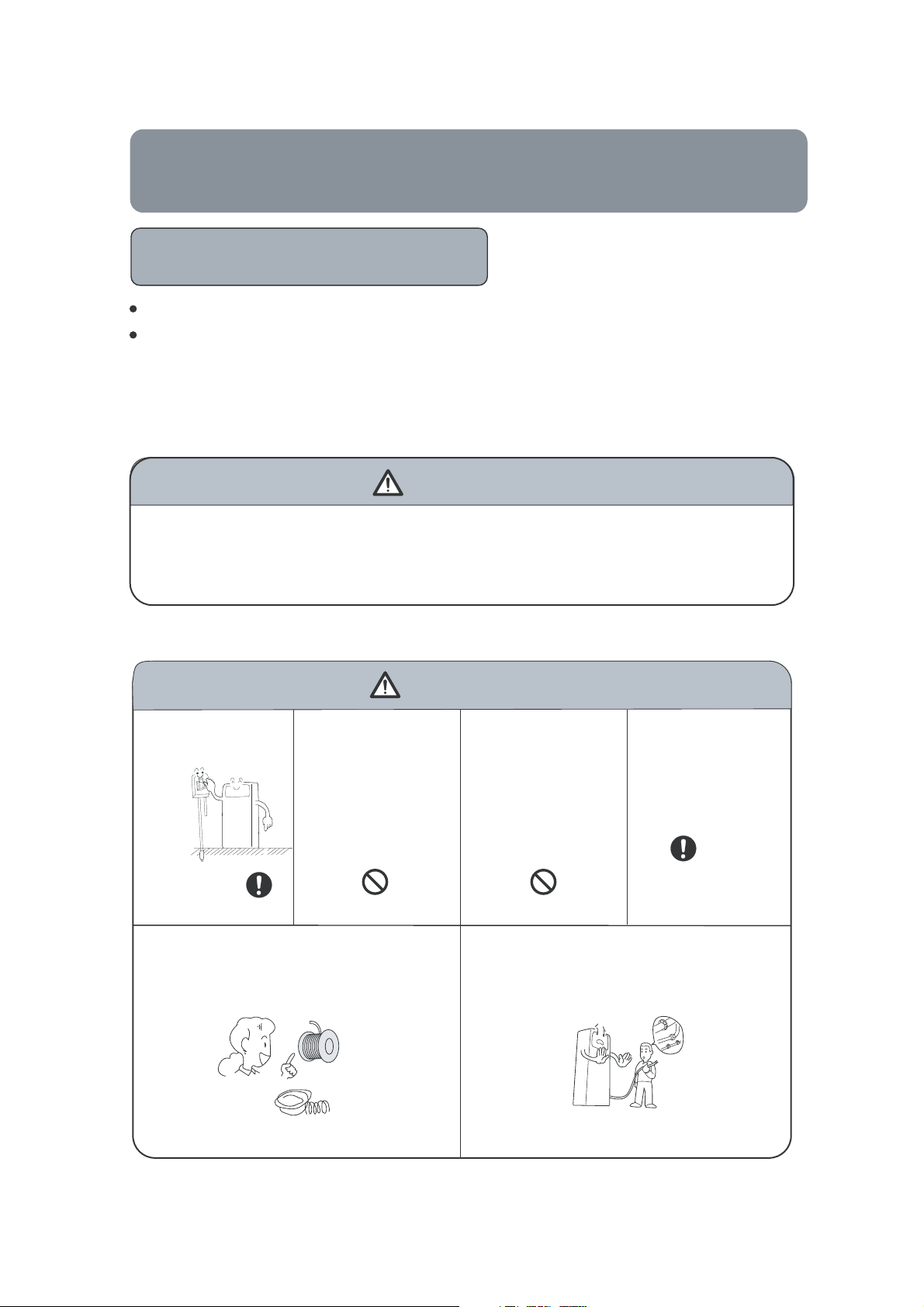
Installation
WARNING
Please call Sales/Service Shop for the Installation.
Do not attempt to install the air conditioner byyourself because improper worksmay
cause electric shock, fire,water leakage.
Installation in an inadequate place may cause accidents. Do not install in the following place.
CAUTION
Connect the earth
cable.
Use fuse with specified capacity.
Replacement with steel or copper wires are
absolutely prohibited.
Do not install in the
place where there
is any possibility
of inflammable
gas leakage around
the unit.
PROHIBITION PROHIBITION
FUSE
Do not get the unit
exposed to vapor
or oil steam.
Grounding wire should not be connected to
that of gas pipeline,water pipeline,lighting
arrester or telephone.
Check proper
installation of the
drainage securely
STRICT
ENFORCEMENT
STEEL WIRE
COPPE
RWIRE
3
Page 5

Cautions
Use of Air Conditioner
WARNING
When abnormality such as burnt-small found, immediately
stop the operation button and contact sales shop.
Use an exclusivepower source with a circuit breaker.
OFF
Connect power supply cord to the
outlet completely.
STRICT
ENFORCEMENT
Do not use power supply cord in
a bundle.
PROHIBITION
Do not start or stop the operation
by disconnecting
cord and so on.
Do not use for the purpose of
storage of food, art work, precise
equipment,
the power supply
PROHIBITION
breeding , or cultivation.
STRICT
ENFORCEMENT
After installed, the unit shall be
tested for electric leakage.
Take
care not to damage the
power supply cord.
PROHIBITION
Do not channel the air flow directly
at people, especially at infants or
the aged.
PROHIBITION
CAUTION
Take fresh air occasionally
especiallywhen gas appliance is
running at the same time.
Donotusepower supply cord
extended or connected in halfway.
PROHIBITION
Do not insert objects into the air
inlet or outlet.
PROHIBITION
Do not try to repair or reconstruct
byyourself.
Do not operate
hand.
the switch with wet
PROHIBITION
Do not install
or other heating apparatus.
Do not place animals or plants in
the direct path of the air flow.
the unit near a fireplace
PROHIBITION
STRICT
ENFORCEMENT
Check good condition of the
installation stand.
PROHIBITIONPROHIBITION
Do not place any objects on or
climb on the unit.
PROHIBITION
4
PROHIBITION
Do not pour water onto the unit
for cleaning.
PROHIBITION
Do not place flower vase or water
containers on the top of the unit.
PROHIBITION
Page 6

Parts and Functions
Indoor unit
1.OUTLET
2.CONTROL PANEL
Outdoor unit
3.INLET GRILLE
4.INLET
HPU-18C03/E1
HPU-18H03/E1
1.OUTLET 3.CONNECTING PIPING AND ELECTRICA
2.INLET 4.DRAIN HOSE
HPU-24C03/E1
HPU-24H03/E1
L WIRING
5
Page 7
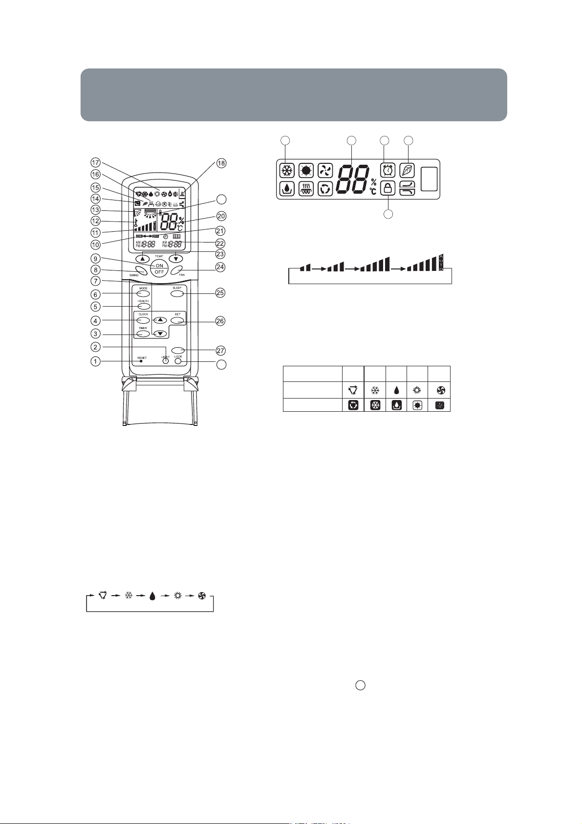
Parts and Functions
17
A
B
19
20
15
14
28
10. TIMER ON display
11. FAN SPEED display
Remote controller
LOW HI
MED AUTO
Control panel: See p17
12. LOCK displa
y
13. SWING UP/DOWN display
14. SLEEP display
15. HEALTH display
E.HEAT
28
16. E.HEAT display
17. Operation mode display
Operation mode
Remote controller
Display board
AUTO FANCOOLDRY
HEAT
18.Singal sending display
19. Left/right air flow display
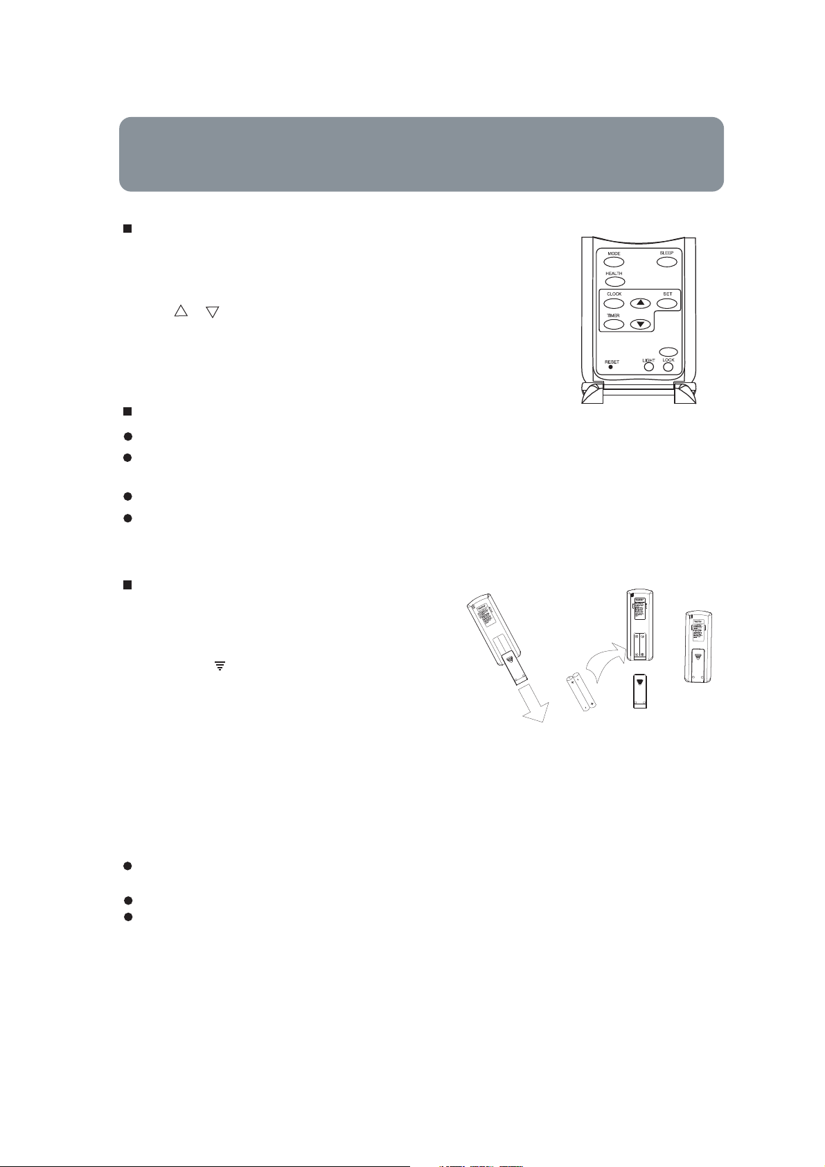
1. RESET
When the remote controller appears abnormal,
use a sharp pointed article to press this button
to reset the remote controller normal.
2. LIGHT button
Control the lightening and extinguishing of
the indoor LED display board.
3. TIMER button
Used to select TIMER ON, TIMER OFF,
TIMER ON-OFF.
4. CLOCK button
Used to set correct time.
5. HEALTH button
Used to set healthy operation.
6. MODE button
AUTO COOLDRY FAN
HEAT
7. HOUR button
Used to set clock and timer setting.
8. SWING UP/DOWN button
Used to select up or down air sending direction.
20. TEMP display
Remote controller: to display the TEMP. setting.
21. TIMER OFF display
22. TIMER display
23. TEMP button
Used to select your desired temperature.
24. FAN button
Used to select fan speed: LOW,MED, HI, AUTO.
25. . SLEEP button
Used to select sleep mode.
26. SET button
Used to confir
27.
E.HEAT button
Used to operate electricity
28.
LOCK
Used to loc
other b
display appears
canceled and lock condition display disappears.
m timer and clock settings.
heat
function.
k b
uttons and LED displa
uttons will be disabled and the loc
. Press it once again, lock will be
y. If pressed, the
k condition
9. ON/OFF button
Used for unit start and stop.
NOTE:(1) The following functions and related displays are not available:
(2) Cooling only unit do not have functions and displays related with heating
5
.
(3)The air conditioner you bought, may not include the E.Heat function, is subject to the actual product.
6
Page 8
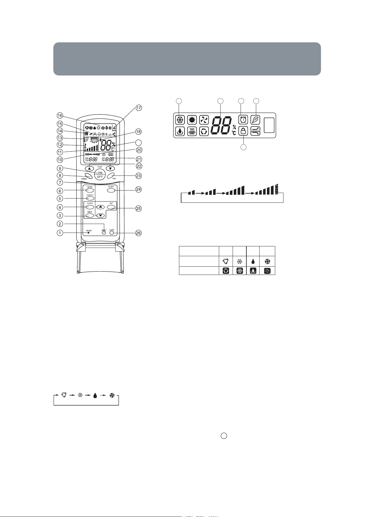
Parts and Functions
16
A
B
19
19
15
14
26
9. ON/OFF button
Used for unit start and stop.
10. TIMER ON display
11. FAN SPEED display
Remote controller
LOW HI
MED AUTO
Control panel: See p17
12. LOCK displa
y
13. SWING UP/DOWN display
14. SLEEP display
15. HEALTH display
16. Operation mode display
Operation mode
Remote controller
Display board
AUTO FANCOOLDRY
17.Singal sending display
18. Left/right air flow display
19. TEMP display
1. RESET
When the remote controller appears abnormal,
use a sharp pointed article to press this button
to reset the remote controller normal.
2. LIGHT button
Control the lightening and extinguishing of
the indoor LED display board.
3. TIMER button
Used to select TIMER ON, TIMER OFF,
TIMER ON-OFF.
4. CLOCK button
Used to set correct time.
5. HEALTH button
Used to set healthy operation.
6. MODE button
AUTO COOLDRY FAN
Remote controller: to display the TEMP. setting.
20. TIMER OFF display
21. TIMER display
22. TEMP button
Used to select your desired temperature.
23. FAN button
Used to select fan speed: LOW,MED, HI, AUTO.
24. . SLEEP button
Used to select sleep mode.
25. SET button
Used to confir
m timer and clock settings.
26. LOCK
Used to lock buttons and LED display. If pressed, the
other buttons will be disabled and the lock condition
display appears. Press it once again, lock will be
canceled and lock condition display disappears.
7. HOUR button
Used to set clock and timer setting.
8. SWING UP/DOWN button
Used to select up or down air sending direction.
NOTE:(1) The following functions and related displays are not available:
(2) Cooling only unit do not have functions and displays related with heating
5
.
7
Page 9
Parts and Functions
Clock Set
When unit is started for the first time and after replacing batteries in
remote controller, clock should be adjusted as follows:
1. Press CLOCK button,"AM" or "PM" flashes.
2. Press or to set correct time. Each press will increase or decrease
1 min. If the button is kept depressed, time will change quickly.
3. After time setting is confirmed, press SET, "AM" or "PM" stop flashing,
while clock starts working.
Remote controller's operation
When in use, put the signal transmission head directly to the receiver hole on the indoor unit.
The distance between the signal transmission head and the receiver hole should be within
7m without any obstacle as well.
Don't throw or knock the remoter controller.
When electronic-started type fluorescent lamp or change-over type fluorescent lamp or
wireless telephone is installed in the room, the receiver is apt to be disturbed in receiving
the signals, so the distance to the indoor unit should be shorter.
E.HEAT
Loading of the battery
Load the batteries as illustrated right
2 R-03 (7#) batteries
Remove the battery cover:
Slightly press" "area and push down the cover
as illustrated.
Load the battery:
Be sure that the loading is in line with the "+" / "-".
request as illustrated on the bottom of the case.
Put on the cover again.
Confirmation indicator:
After pressing power ON/OFF, if no display, reload the batteries.
Note:
Full display or unclear display during operation indicates the batteries have been used up.
Please change batteries.
Used two new same-typed batteries when loading.
If the remote controller can't run normally during operation, please remove the batteries and
reload several minutes later.
Hint:
Remove the batteries in case unit won't be in usage for a long period. If there are any display
after taking-out, just need to press reset key.
8
Page 10

Operation
AUTO Operation
Control panel
Remote Controller
1. Unit start
Press ON/OFF on the indoor unit,or press ON/OFF on the
remote controller, unit starts.
The liquid crystal will display the working state of last
time (Expcept Timer and Sleep ).
2.3.Select operation mode
Press MODE button. For each press, operation mode
changes as follows:
Remote controller:
AUTO COOL DRY FAN
HEAT
Control panel:
Then Select AUTO operation
1
4
Control panel: See p17
E.HEAT
4. Unit stop
ON/OFF button, the unit stops.Press
About AUTO mode
In this mode, the air conditioner will automatically select
cooling ǃ heating or fan operation mode according to room
temperature.
AUTO COOL DRY FAN
HEAT
9
Page 11

AUTO COOL DRY FAN
HEAT
AUTO COOL DRY FAN
HEAT
E.HEAT
Page 12
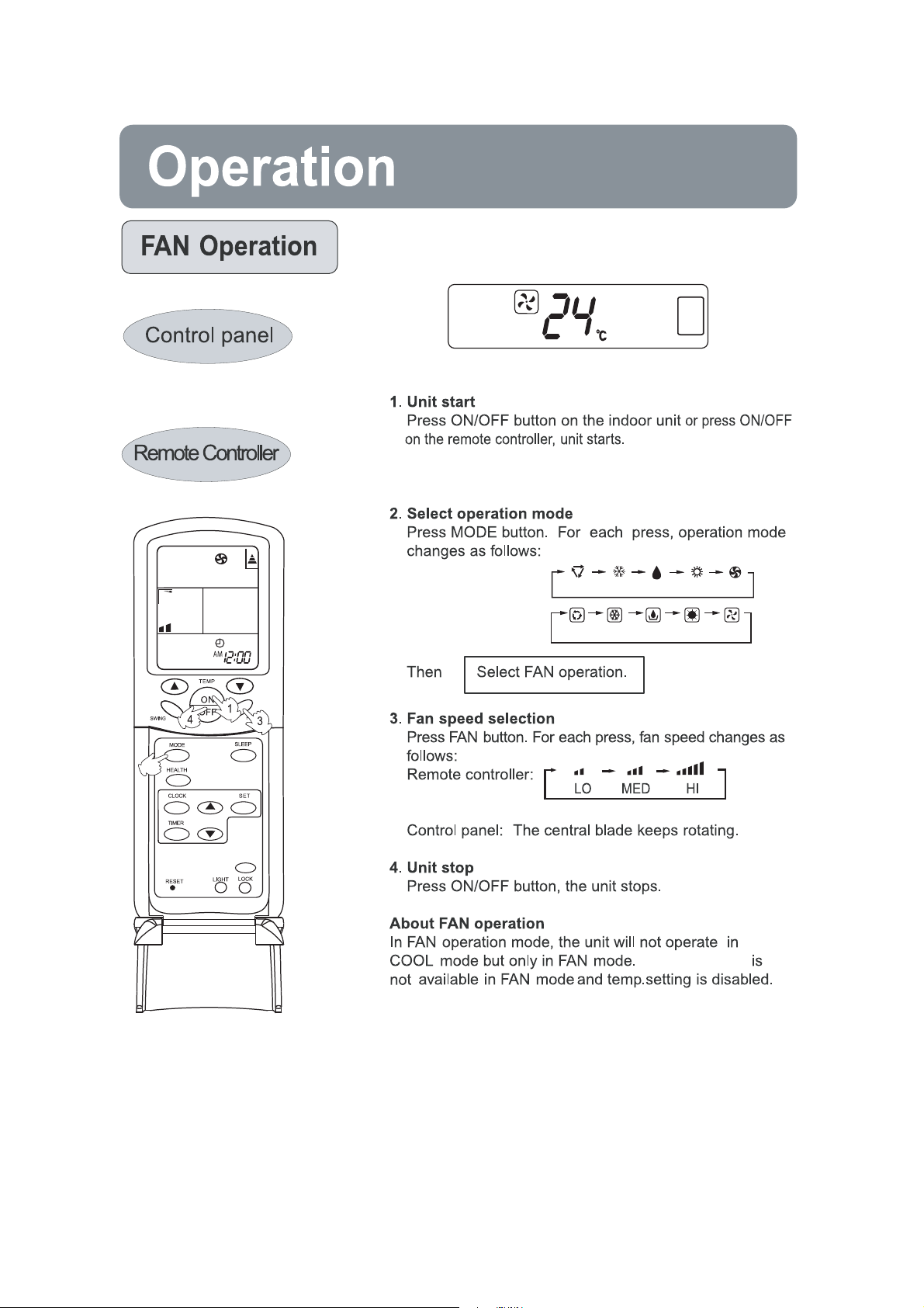
Operation
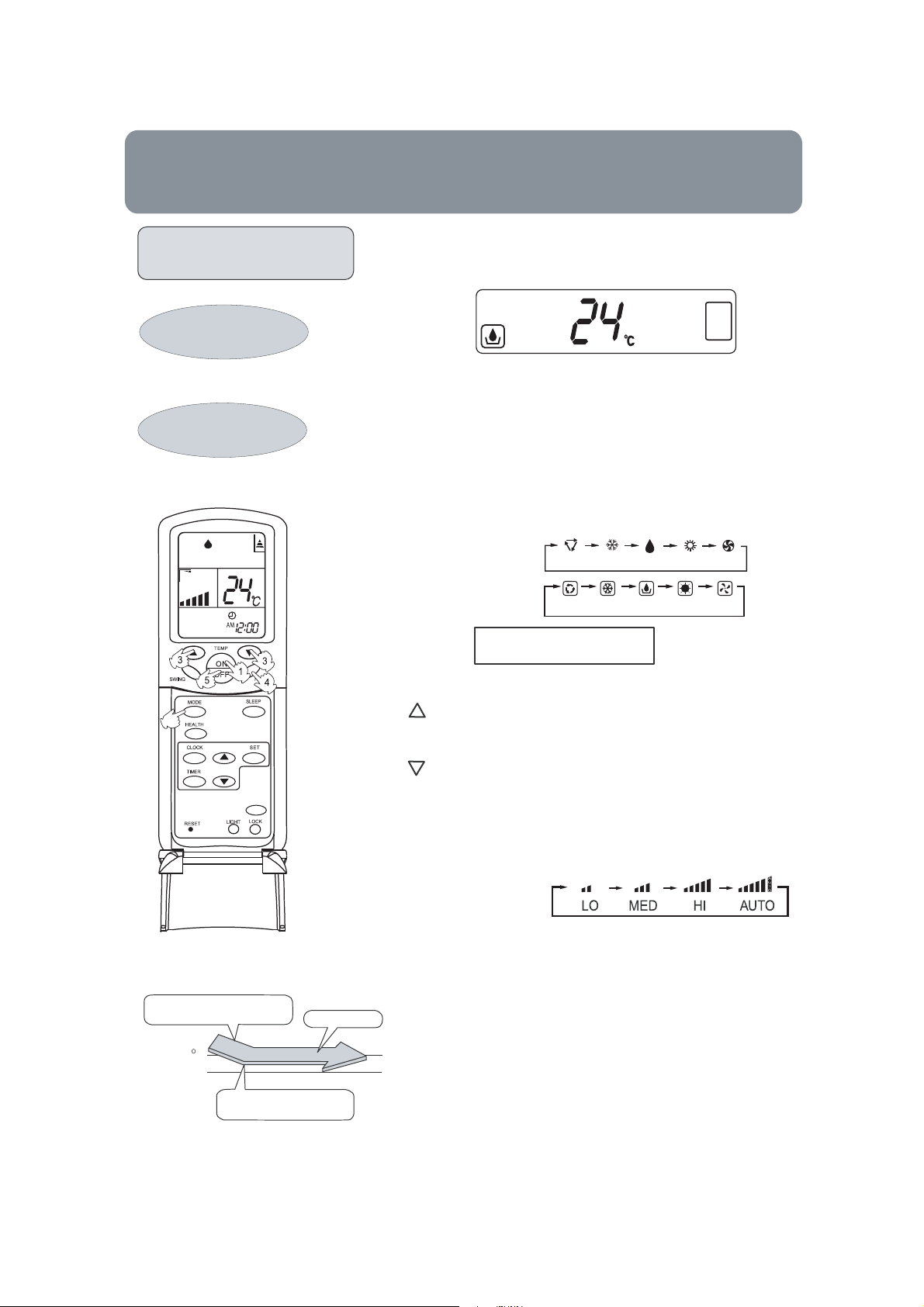
DRY Operation
Control panel
1.Unit start
Remote Controller
2. Select operation mode
Press ON/OFF button on the indoor unit
or press ON/OFF
on the remote controller, unit starts.
The liquid crystal will display the working state of last
time (Expcept Timer, Sleep ).
Press MODE button. For each press, operation mode
changes as follows:
Remote controller:
$8 7 2 &22/ ' 5 < )$1
+( $ 7
COOL operation starts when room
temp. is higher than temp. setting.
Temp. setting+2 C
Temp. setting
On reaching temp. setting +2°C,
unit will run in mild DRY mode.
E.HEAT
Ultra-low air flow
Control panel:
+(
$8 7 2 &22/ ' 5 < )$1
$7
Then Select DRY operation.
3.Select temp.setting
Press TEMP
. button.
Every time the button is pressed, temp. setting
increases 1°C
, if kept depressed, it will increase
rapidly.
Every time the button is pressed, temp. setting
decreases 1°C, if kept depressed, it will decrease
rapidly.
4. Fan speed selection
Press FAN button. For each press, fanspeedchangesas
follows:
Remote controller:
Air conditioner is running under displayed wind speed.
In DRY mode: (1)When room temperature becomes 2°C
higher than temp. setting, unit will run at setting at Temp..
speed regardless of FAN setting; (2)When room temperature
becomes between temp. setting and temp.setting+2°C,
unit will run at setting at LO; (3)
becomes
with 10 minutes
lower than temp. setting, unit will run
ON and 6 minutes OFF .
When room temperature
spasmodically
5. Units top
Press ON/O
FF button, the unit stops.
11
Page 13

Operation
HEAT Operation
Remote controller
E.HEAT
1. Unit start
Press ON/OFF on the remote controller, unit starts.
2.Select operation mode
Press MODE button. For each press, operation mode
changes as follows:
HEAT
HE
AT
Remote controlle
AUTO COOLDRY FAN
r:
AUTO COOLDRY FAN
Then Select HEAT operation
3.Select temp.setting
Press TEMP. button
Every time the button is pressed, temp.setting
increase 1
rapidly
Every time the button is pressed, temp.setting
decrease 1
rapidly
Select a desired tempe
4. Additional electricalheating devices used for heating
Press the E.Heat button, the remote controller and the
operation panel will display ” “ ”separately, a nd the
electrical heating devices will st art to run. the
E.Heat button again, the will disappear and the
devices will stop. About the operation condition for
electrical heating devices.
o
C,if kept depressed, it will increas
o
C,if kept depressed, it will decreas
rature.
“
“
” “ ”
Press
5.Unit stop
Press ON/OFF button, the unit stops.
Operation condition for electrical heating (Cooling only model does not include)
After the E.Heat function has been allowed, the microcomputer in airconditioner
will meterage the indoor temperature. If the indoor temperature is less than or
equal to 22
art to run, otherwise, the devices will stop running automaticly.
st
o
C , and 2oCless than the defined temperature, the E.Heat devices will
12
Page 14
The liquid crystal will display the working state of last
time (Expcept Timer and Sleep).
changes as follows:
AUTO COOLDRY FAN
Remote controlle
r:
AUTO COOLDRY FAN
2
E.HEAT
HEAT
HE
AT
Auto fan speed
13
Page 15

SLEEP Operation
Before going to bed, you can simply press the
SLEEP button and unit will operate in SLEEP
mode and bring you a soundless sleep.
Use of SLEEP function
After the unit starts, set the operation status,
then press SLEEP button before which the
clock must be adjusted and time being set.
Operation Mode
1. In COOL,DRY mode
1 hours after SLEEP mode starts, temp. will
become 1
another 1 hours, temp. rises by 1
The unit will run for further 6 hours then stops.
Temp. is higher than temp. setting so that room
temperature won't be too Iow for your sleep.
O
C higher than temp. setting. After
Remote Controller
O
C further.
SLEEP operation starts SLEEP operation stops
Approx.6hrs
Rises 1
1 hr
O
C
Rises 1
1 hr
Temp.setting
In COOL, DRY mode
In HEAT mode
2.
1 hours after SLEEP mode sta
will become 2
. After another 1 hours, temp
setting
decrease
another 3 hour
rther. The unit will run for further 3
fu
hours then stop
p. setting so that room temperature
tem
O
C lower than temp.
O
C further. After more
by 2
s, temp. rises by 1
s. Temp. is lower than
won't be too high for your sleep.
O
C
Unit stop
rts, temp
O
C
E.HEAT
SLEEP
operation starts
AUTO mode
In
3.
The unit ope
Temp.setting
1 hr
Decreases 2OC
1 hr
Decreases 2
3 hrs
In HEAT mode
rates in corresponding sleep
Unit stop
O
C
3 hrs
Rises 1OC
SLEEP
operation stops
mode adapted to the automatically selected
ope
ration mode.
4. In FAN mode
It has no SLEEP function.
5.Set the wind speed change when sleeping
If the wind speed is high or middle before
setting for the sleep, set for lowing the wind
speed after sleeping.
If it is low wind, no change.
14
Page 16

TIMER
(+($7
0/
0''
0/
0/
10
10
0''
0''
0/
0''
15
Page 17

Operation
TIMER On-Off Operation
Control panel
Set clock correctly before starting TIMER operation.
1. After unit starts, select your desired operation mode.
2. Timer mode selection
Remote Controller
3. Time setting
4. Time confirming for TIMER ON
E.HEAT
5. Time setting for TIMER OFF
6. Time confirming for TIMER OFF
To cancel TIMER mode
Operatio
Press TIMER button to change TIMER mode. Every
time the button is pressed, display changes as follows:
Remote controller:
Then select your desired TIMER mode (TIMER ON or
TIMER OFF). " " will flash.
Press HOUR / button.
Every time the button is pressed, time setting
increases 10min, if kept depressed, it will increases
rapidly.
Every time the button is pressed, time setting
decreases 10min, if kept depressed, it will decreases
rapidlly.
It can be adjusted
After setting correct time, press TIMER button to confirm.
" " on the remote controller stops flashing.
" " starts flashing.
Just press HOUR button, follow the same procedure in
"Time setting for TIMER ON ".
After time setting, press SET button to confirm.
" " on the remote controller stops blinking.
Time displayed: Unit stops at X hour X min.
n mode will be displayed on LCD.
0/
0/
0''
Time displayed: Unit starts or stops at x hour x min.
0''
0''
0/
within 24 hours.
0/
0''
Just press TIMER button several times until TIMER
mode disappears.
According to the Time setting sequence of TIMER ON
or TIMER OFF, either Start-Stop or Stop-Start can be
achieved.
16
Page 18

Operation
FAN speed display
108&3
.0%&
'"/
When adjusting FAN speed during system
operation, every time the FAN button is pressed,
&-&$
)&"5
5&.1
5&.1
fan speed changes as follows:
AUTO LOMED HI
After setting the fan speed, the fan speed display on the operation panel will quit after blinking 5 seconds,
then the operation panel will display the indoor temperature.In case the air-flow model is in motion, touch
the air circulation button on the operation panel, the fan speed display will blink for 5 seconds, and the sign
“ ” of air-flow model will keep bright, while the ‘1’. ’2’. ’3’ sign will disappear.
TEST OPERATION
o
Use this switch in the test operation when the room
do not use it in the normal
operation.
temperature is less 16
Unit start
Continue to press the ON/OFF button
After you hear the " Hua " sound twice,release your finger from
the test operation startsand the
air conditioner starts with the air flow speed
for more than 5 seconds.
the switch,
setting "Hi".
Unit stop(to cancel test operation)
Push the or operate with remote
ON/OFF button
controller
to cancel the test run.
If you use the remote controller to cancel the test run, the conditioner will then run
per the working mode displayed on the remote controller.
,
C
Air Flow Direction Adjustment
5&.1
vertical flap
IPSJ[POUBM
louvers
The Swing button on the remote controller, once been touched, the swing mode of the plastic
flap and the horizontal louver will be changed following the formula below:
plastic flap swings--- plastic flap stop--- horizontal louver swings--- horizontal louver stop
--- both swings--- both stop
17
48*/(
.0%& 4-&&1
)&"-5)
$-0$,
5*.&3
3&4&5
0''
0/
4&5
&)&"5
-0$,
-*()5
'"/
Page 19

Maintenance
Maintenance at the end of application season
On a fine day, unit shall be started and operate in
FAN mode for about half a day until the inside of
the unit becomes thoroughly dry.
Turn off the unit operation switch and power on/off.
Otherwise,there will be some electricity consumption
even the unit is in stop status.
Clean the filter and indoor,outdoor unit,cover
the units well.
Maintenance before beginning of aplication season
Check there are no obstacles in the air inlet and
outlet to avoid impairing of working efficiency.
Please do attach the air filter to ensure the
electrostatic filters not soiled.Otherwise,dirt
will come into and damage the unit or bring
failures.
18
Page 20

19
Page 21

Maintenance
Cleaning of the unit
Turn off the power switch
Take off the air inlet grille
Take off the inlet grille by pulling each ends
of the inlet grille outword.
Clean the filter
Use
water or vacuum cleaner to remove
dust. If it is too dirt, clean with detergent or
neutral soap water.
Rinsing with fresh water, dry the filter and
re-assemble.
Do not touch with wet hand
Do not clean with hot
water or solvent
Caution:
Do not wash filter in hot water above 40°C,
which will damage the filter.
Do carefullywipe the filter.
Clean the indoor(outdoor) unit
Clean with warm cloth or neutral detergent,
then wipe away moisture with dry cloth. Do
not use too hot water(above 40°C),which will
cause discoloration or deformation. Do not
use pesticide or other chemical detergents.
20
Page 22

Installation Manual of Room Air Conditioner
DN
than
morethan
DN
more
Installation of indoor unit
morethan
DN
DN
morethan
Installation of outdoor unit
selection of installation place
Place strong enough to support the unit and will
not cause vibration and noise.
Place where discharged wind and noise doesn,t
cause a nuisance to the neighbors.
Place where is less affected by rain or direct sunlight
and is sufficientlyventilated,or to install a shield.
Place with enough space for smooth air flow.
m
ore
th
a
n10
selection of installation place
Place where it is easy to route drainage pipe
and outdoor piping.
Place away from heat source and with less
direct sunlight.
Place where cool and warm air could be
delivered evently to every corner of the room.
Place near power supply socket.Leave enough
space around the unit.
Place robust not causing vibration,where the
body can be supported sufficiently.
m
c
10
n
a
ore th
m
cm
more than
10 cm
more
21
than 60 cm
Page 23

Trouble shooting
Before asking for service, check the following first.
Normal
Performance
inspection
Phenomenon
The system does not restart
immediately.
Noise is heard
s are generated.
Smell
Mist or steam are blown out.
Cause or check points
When unit is stopped, it won't restart
immediately until 3 minutes have elapsed
to protect the system.
When the electric plug is pulled out and
reinserted, the protection circuit will work
for 3 minutes to protect the air conditioner.
During unit operation or at stop, a swishing
or gurgling noise may be heard. At first 2-3
minutes after unit start, this noise is more
noticeable. (This noise is generated by
refrigerant flowing in the system.)
During unit operation, a cracking noise may
be heard. This noise is generated by the
casing expanding or shrinking because of
temperature changes
Should there be a big noise from air flow in
unit operation, air filter may be too dirty.
This is because the system circulates smells
from the interior air such as the smell of
furniture, cigarettes.
During COOL or DRY operation, indoor unit
may blow out mist. This is due to the sudden
cooling of indoor air.
Multiple
check
Does not work at all.
Poor cooling
Is power plug inserted?
Is there a power failure?
Is fuse blown out?
Is the air filter dirty? Normally it should be
cleaned every 15 days.
Are there any obstacles before inlet and outlet?
Is temperature set correctly?
Are there some doors or windows left open?
Is there any direct sunlight through the
window during the cooling operation?(Use
curtain)
Are there too much heat sources or too many
people in the room during cooling operation?
22
Page 24

Installation Manual of Room Air Conditioner
Tool necessary
1. Screw driver
2. Hacksaw
3. 70mm dia.hole core drill
4. Spanner(dia. 17,27mm)
5. Spanner(14,17,19, 27mm)
6. Pipe cutter
7. Flaring tool
8. Knife
9. Nipper
10. Gas leakage detector
or soap water
11. Measuring tape
12. Reamer
13. Refrigerant oil
Standard accessories
Following parts shall be field
supplied
Shape and description
No.
Remote controller
Cement nail
Connecting pipe
Drain hose
Wire clip
Insulation pipe
Wall
hole cover
Piping hole cover
Dry battery #7
Rubber pad
QTY
Mark
A
B
C
D
E
F
Part name
Adhensive tape
Pipe clip
Connecting hose
Insulation material
Putty
Drain hose
Fixing of the unit
1. Position of the wall hole
Wall hole should be decided according to installation
place and piping direction.(refer to installation drawings).
2. Making a wall hole
Drill a hole of 70X70mm dia. with a little slope towards
outside.
Non-adhensive tape
TJHOBMIPTF
Indoor side
Wall hole
70mm
(Cross section of wall hole)
Outdoor side
Thickness
of wall
23
Page 25

Installation Manual of Room Air Conditioner
3. Piping connection
Connecting method
To bent a pipe, give the roundness as large as possible not to crash the pipe.
When connecting pipe, hold the pipe center to center then screw nut on by hand, refer to Fig.
Be careful not to let foreign matters, such as sands enter the pipe.
Piping connection of the indoor unit
1. Arrangement of piping and drainage pipe
After opening inlet grill, you will see a control
box as shown in the Fig.
Remove the cover before working.
Cut away, w ith hammer or a saw, the lid for piping according to piping direction.
Drain hose
Copper tube
Insulation material
According to the piping method, connect the piping on indoor unit with union of connection pipe.
Arrange the piping as per the wall hole and bind drain hose connecting electric cable and piping
together with polyethylene tape.
Insert the bound piping connecting electric cable and drain hoes through wall hole to connect
with outdoor unit.
2. Arrangement drain hose
Drain hose shall be placed in under place.
There should be a slope when arrange drain hose. Avoid up and down waves in drain hose.
If humidity is high, drain pipe(especially in room and indoor unit) must be covered with
installation material.
Connecting electric cable
for indoor and outdoor unit
24
Page 26

Installation Manual of Room Air Conditioner
1. Piping connection of the outdoor unit
Connecting the connecting pipe and inlet and
outlet liqued pipe
according to the piping method.
2.The connecting method of U-model terminal block:
Release the screws, put the connecting wire's U-model terminal block between the screw and
terminal-block Base, then tighten the screws. Draw the wire lightly to make sure the block have
been compacted.
Purging Method:
Push the air out of the indoor unit
and piping as followes:
(1) Remove the valve cap on 2-way
valve in outdoor unit.
(2) Loosen by 1/2 turn the flare nut of
gas pipe, which is conneted to
3-way valve.
o
(3) Loosen 2-way valve by 90
using
hexagon wrench, and after approx.
6 sec tighten it up. Gas comes out
through flare nut on wide pipe. If no
gas is discharged, tighten flare nut
with specified torque.
(4) Open 2-way and 3-way valves
using specified torque.
(5) Tighten the caps on the valves
with specified torque.
Liquid side
2-wayvalve
Forced fastening without careful
centering may damage the
threads and cause
gas.
Pipe Diameter ( )
Liquid Side 6.35mm(1/4")
Gas Side 15.88mm(1/2") 50N.m
Liquid Side 9.52mm(3/8")
Gas Side 15.88mm(5/ 8") 60N.m
Gas side
3-wayvalve
2-wayvalve
3-wayvalve
a leakage of
Fastening Torque
18N.m
42N.m
Liquid side
NN
Gas side
NN
Outdoor unit
Outdoor unit
Indoor unit
Max. Length:
for 18K 24K: A=20m
Oil trap
A
CAUTION
In case more than 5m
Max.Elevation:
for 18K 24K: 10m
no more gas if the length of connecting pipe is less than
Indoor unit
The height di
fference between any two indoor or outdoor units can not be
Oil trap shoud be installed every 5~7m
20m(18K 24K).
more than 10m(18K 24K).
Note: When extending piping, air inside piping shall be removed by using external refrigerant gas,
charge according to the following list.
Brand new outdoor unit is charged 50g or 80g(24k) more refrigerant than regulated weight. Only for
first installation, this extra 50g or 80g(24k) can be used to purge airin pipes.
During this procedure, 50g or 80g(24k) refrigerant will be discharged in piping.(This must be
strictly controlled within 90
o
and 10 sec.)
25
Page 27

Installation Manual of Room Air Conditioner
Note: When additional refrigerant is necessary, first purge air out of connecting pipe by external gas,
then drive out the excessive rerigerant by purging method.
Brand new unit is charged 80g more refrigerant than spec. This is only for first instaltion to purge air
in the indoor unit and connecting pipe.
When piping is longer than 5m, charge additional refrigerant specified in this list.
Pipe length 5m
Refrigerant charge(g)
10m 15m
100
200
Pipe length 5m 10m 15m
Refrigerant charge(g)
Electric wiring
Note:
Electric wiring must be done byqualified person.
Use copper wire only.
The parameter of the connecting cable:
HPU-18H03/E1: 3*2.5+2*0.75 HPU-18C03/E1˖3*2.5
HPU-24H03/E1˖3*2.5+3*0.75 HPU-24C03/E1 ˖ 4*0.75
Wiring of indoor unit
Insert the cable from outside the wall hole where piping already exist.
Pull it out from front.
Losen terminal screw and insert cable end fully into terminal block, then
Pull the cable gently to make sure it is tight.
Replace cover after wiring.
Indoor unit
/-
/
-
Indoor unit
Indoor unit
Indoor
tighten it
Indoor unit
300
600
1(L)
Outdoor unit
+38&(
Outdoor unit
+38&(
Outdoor
/
1
Outdoor unit
+38+(
Outdoor unit
+38+(
Note: User should prepare the part in the dashed
Wiring of outdoor unit
Insert the cable
from inside the wall hole where piping already exist.
frame by himself.
Pull it out from front.
Loose terminal screw and insert cable end fully into terminal block, then tighten it
Pull the cable gently to make sure it is tight.
Replace cover after wiring.
Note:
When connecting indoor and outdoor wire, check the number on indoor and outdoor terminal
blocks. Terminals of same number and same color shall be connected by the same wire.
Incorrect wiring may damage air conditioner's control or cause operation failure.
26
Page 28
Installation Manual of Room Air Conditioner
Others
1. Power supply
Air conditioner must use an exclusive line(over 30A) and there is not power plug with this type,
the type of power supplyw
ire HPU-18/24C03/E1ǃHPU-18H03/E1 is
2.5mm
When installation air conditoner in a wet place, try to use a circuit breaker against Current
leakage.
For installation in other palces, use circuit breaker as far as possible.
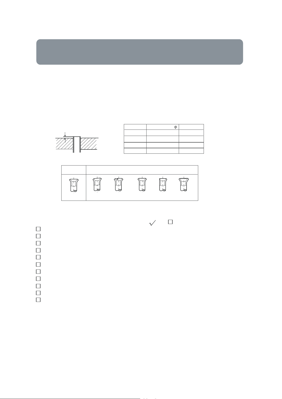
2. Piping cutting and flaring
Besuretocarry out deburring after cutting w ith a pipe cutter.
Insert flaring tool to makeaflare.
A
Correct Incorrect
Flare tooling die
Liquid pipe
Gas pipe
Liquid pipe
Gas pipe
Pipe diameter
6.35mm(3/8")
12.7mm(5/8")
9.52mm(3/8")
15.88mm(5/8")
2
HPU-24H03/E1 is 4
Size A (mm)
0.8 ~1.5
1.2 ~2.0
1.0 ~1.2
1.4 ~2.2
0mm2.
Lean
Damage of flare Crack Partial Too outside
Installation inspection and test run:
Please operate unit according to this Manual.
Items to be checked during test run. Please made a '' '' in '' ''
Are there any gas leakage?
How is insulation at piping connection carried out?
Are electric wires of indoor and outdoor unit firmly inserted into terminal block?
Is electric wiring of indoor and outdoor securely fixed?
Is drainage securely carried out?
Is earth line(grounding) securely connected?
Ispower supplyvoltage abided by the code?
Is there any noise?
Is control display normal?
Is cooling operation normal?
Is room temp. regulator normal?
27
 Loading...