

Page 1
SERVICE MANUAL
LED LCD TV
Model No.
HL40XSL2
Service mode HL40XSL2a
MTK5305
Chassis
WARNING
This service information is designed for experienced repair technicians only and is not designed for use by the general public.
It does not contain warnings or cautions to advise non-technical individuals of potential dangers in attempting to service a product.
Products powered by electricity should be serviced or repaired only by experienced professional technicians. Any attempt to service or repair
the product or products dealt with in this service information by anyone else could result in serious injury or death.
©2009 Qingdao Haier Electronics Co., Ltd.
All rights reserved. Unauthorized copying and distribution is a violation of law.
Haier Group
Page 2

CONTENTS
Chapter 1.General Information
Service Manual
Model No.: LEA40T3
1-1. Document Information
1-2. General Guidelines
1-3. Important Notice
1-3-1. Follow the regulations and warnings .....................................................3
1-3-2. Be careful to the electrical shock ...........................................................3
1-3-3. Electro static discharge (ESD) ...............................................................3
1-3-4. About lead free solder (PbF) ..................................................................4
1-3-5. Use the genewing parts (specifi ed parts) ..............................................4
1-3-6. Safety check after repairment ................................................................4
1-3-7. Ordering Spare Parts .............................................................................6
1-3-8. Photo used in this manual .....................................................................6
...................................................................................3
1-4. How to Read this Service Manual
1-4-1. Using icons: ...........................................................................................7
.......................................................................3
..............................................................................3
..................................................7
Chapter 2. Specifi cation
2-1. Specifi cation list
2-2. External pictures (four faces)
...................................................................................8
..........................................................9
Chapter 3. Disassemble and Assemble
3-1. Remove the Stand
3-2. Remove the Power Cord
3-3. Remove the Back Cover
3-4. Remove the Mainboard
3-5. Remove the speaker
3-6. Remove the Keypad
3-7. Remove the Remote Control Board
3-8. Remove the Stand backstop
3-9. Remove the indicator light
.............................................................................10
................................................................ 11
.................................................................. 11
................................................................... 11
........................................................................ 11
.........................................................................12
...........................................12
.........................................................12
............................................................12
Chapter 4. Location of Controls and Components
4-1. Board Location
4-2. Main Board
4-2-1. Function Description: ...........................................................................14
4-2-2. Connector defi nition .............................................................................14
4-3. Power Supply Board
...................................................................................13
..........................................................................................13
.........................................................................14
1
Page 3

Service Manual
4-4
h
2
2
27-3
2
2
3-4
Model No.: LEA40T3
4-3-1. Function description:............................................................................14
4-3-2. Connector defi nition: ............................................................................14
4-4. LCD Panel
4
4-4-1. Function Description: Display the signal. .............................................16
4
4-4-2. Connector defi nition: ............................................................................16
Chapter 5. Installation Instructions
C
.............................................................................................15
5-1. External Equipment Connections
5-
5-2. HDMI Connections
5-
Chapter 6. Operation Instructions
C
6-1. Get to know your TV
6-
6-2. Get to know your remote control
6-
Chapter 7. Electrical Parts
C
7-1. Block Diagram
7-
7-2. Circuit Diagram
7-
7-3. Wiring Connection Diagram
Chapter 8. Measurements and Adjustments
C
8-1. Service Mode
-
8-1-1.How to enter into Service Mode............................................................46
8-1-2.How to exit ............................................................................................46
8-2. Measurements and Adjustments
-
8-2-1. The Main Menu ....................................................................................46
8-2-2. Video ....................................................................................................47
8-2-3. Audio ....................................................................................................48
8-2-4. Software UpDate .................................................................................48
......................................................................................46
.............................................................................24
.........................................................................27
.....................................................................................29
...................................................................................31
...........................................................45
................................................20
.................................................28
..................................................46
Chapter 9. Trouble shooting
C
9-1. Simple check
-
9-2. Power Supply Board Failure Check.
-
9-3. Mainboard Failure Check
-
9-4. Pannel Failure
2
.......................................................................................49
...............................................................51
.....................................................................................52
...........................................50
Page 4

Service Manual
Model No.: LEA40T3
Chapter 1.General Information
1-1. Document Information
Document format: Adobe PDF
Author:
Compiler:
1-2. General Guidelines
When servicing, observe the original lead dress. If a short circuit is found, replace all parts which
have been overheated or damaged by the short circuit.
After servicing, see to it that all the protective devices such as insulation barriers, insulation papers
shields are properly installed.
After servicing, make the following leakage current checks to prevent the customer from being
exposed to shock hazards.
1) Leakage Current Cold Check
2) Leakage Current Hot Check
3) Prevention of Electro Static Discharge (ESD) to Electrostatically Sensitive
1-3. Important Notice
1-3-1. Follow the regulations and warnings
Most important thing is to list up the potential hazard or risk for the service personnel to open
the units and disassemble the units. For example, we need to describe properly how to avoid the
possibility to get electrical shock from the live power supply or charged electrical parts (even the
power is off).
This symbol indicates that high voltage is present inside.It is dangerous to make any
kind of contact with any inside part of this product.
This symbol indicates that there are important operating and maintenance instructions
in the literture accompanying the appliance.
1-3-2. Be careful to the electrical shock
To prevent damage which might result in electric shock or fire, do not expose this TV set to
rain or excessive moisture. This TV must not be exposed to dripping or splashing water, and
objects fi lled with liquid, such as vases, must not be placed on top of or above the TV.
1-3-3. Electro static discharge (ESD)
Some semiconductor (solid state) devices can be damaged easily by static electricity.
Such components commonly are called Electrostatically Sensitive (ES) Devices. The following
3
Page 5

Service Manual
Model No.: LEA40T3
techniques should be used to help reduce the incidence of component damage caused by
electros static discharge (ESD).
Electrostatically Sensitive (ES) Devices
Some semiconductor (solid-state) devices can be damaged easily by static electricity. Such
components commonly are called Electrostatically Sensitive (ES) Devices. Examples of typical
ES devices are integrated circuits and some field-effect transistors and semiconductor "chip"
components. The following techniques should be used to help reduce the ncidence of component
damage caused by static by static electricity.
1. Immediately before handling any semiconductor component or semiconductor-equipped
assembly, drain off any electrostatic charge on your body by touching a known earth ground.
Alternatively, obtain and wear a commercially available discharging wrist strap device, which
should be removed to prevent potential shock reasons prior to applying power to the unit under
test.
2. After removing an electrical assembly equipped with ES devices, place the assembly on a
conductive surface such as aluminum foil, to prevent electrostatic charge buildup or exposure of
the assembly.
1-3-4. About lead free solder (PbF)
This product is manufactured using lead-free solder as a part of a movement within the
consumer products industry at large to be environmentally responsible. Lead-free solder must be
used in the servicing and repairing of this product.
1-3-5. Use the genewing parts (specifi ed parts)
Special parts which have purposes of fi re retardant (resistors), high-quality sound (capacitors),
low noise (resistors), etc. are used.
When replacing any of components, be sure to use only manufacture's specifi ed parts shown in
the parts list.
Safety Component
● Components identifi ed by mark have special characteristics important for safety.
1-3-6. Safety check after repairment
Confi rm that the screws, parts and wiring which were removed in order to service are put in the
original positions, or whether there are the positions which are deteriorated around the serviced
places serviced or not. Check the insulation between the antenna terminal or external metal and
the AC cord plug blades. And be sure the safety of that.
General Servicing Precautions
1. Always unplug the receiver AC power cord from the AC power source before:
4
Page 6

Service Manual
Model No.: LEA40T3
a. Removing or reinstalling any component, circuit board module or any other receiver
assembly.
b. Disconnecting or reconnecting any receiver electrical plug or other electrical connection.
c. Connecting a test substitute in parallel with an electrolytic capacitor in the receiver.
CAUTION:
may result in an explosion hazard.
2. Test high voltage only by measuring it with an appropriate high voltage meter or other voltage
measuring device (DVM, FETVOM, etc) equipped with a suitable high voltage probe.
Do not test high voltage by "drawing an arc".
3. Do not spray chemicals on or near this receiver or any of its assemblies.
4. Unless specified otherwise in this service manual, clean electrical contacts only by applying
the following mixture to the contacts with a pipe cleaner, cotton-tipped stick or comparable nonabrasive applicator; 10% (by volume) Acetone and 90% (by volume) isopropyl alcohol (90%-99%
strength).
CAUTION:
Unless specifi ed otherwise in this service manual, lubrication of contacts is not required.
Capacitors may result in an explosion hazard.
5. Do not defeat any plug/socket B+ voltage interlocks with which receivers covered by this
service manual might be equipped.
A wrong part substitution or incorrect polarity installation of electrolytic capacitors
This is a fl ammable mixture.
6. Do not apply AC power to this instrument and/or any of its electrical assemblies unless all
solid-state device heat sinks are correctly installed.
7. Always connect the test receiver ground lead to the receiver chassis ground before connecting
the test receiver positive lead.
Always remove the test receiver ground lead last. Capacitors may result in an explosion
hazard.
8. Use with this receiver only the test fi xtures specifi ed in this service manual.
CAUTION:
9. Remove the antenna terminal on TV and turn on the TV.
10. Insulation resistance between the cord plug terminals and the eternal exposure metal should
be more than Mohm by using the 500V insulation resistance meter.
11. If the insulation resistance is less than M ohm, the inspection repair should be required.
If you have not the 500V insulation resistance meter, use a Tester. External exposure metal:
Antenna terminal Headphone jack.
Do not connect the test fi xture ground strap to any heat sink in this receiver.
12. Use only a grounded-tip soldering iron to solder or unsolder ES devices.
5
Page 7

Service Manual
Model No.: LEA40T3
13. Use only an anti-static type solder removal device. Some solder removal devices not
classifi ed as "anti-static" can generate electrical charges suffi cient to damage ES devices.
14. Do not use freon-propelled chemicals. These can generate electrical charges sufficient to
damage ES devices.
15. Do not remove a replacement ES device from its protective package until immediately
before you are ready to install it.
(Most replacement ES devices are packaged with leads electrically shorted together by
conductive foam, aluminum foil or comparable conductive material).
16. Immediately before removing the protective material from the leads of a replacement ES
device, touch the protective material to the chassis or circuit assembly into which the device will
be installed.
CAUTION:
precautions.
17. Minimize bodily motions when handling unpackaged replacement ES devices. (Otherwise
harmless motion such as the brushing together of your clothes fabric or the lifting of your foot
from a carpeted fl oor can generate static electricity suffi cient to damage an ES device.)
Be sure no power is applied to the chassis or circuit, and observe all other safety
1-3-7. Ordering Spare Parts
Please include the following informations when you order parts. (Particularly the Version letter)
1. Model number, serial number and software version
The model number and serial number can be found on the back cover of each product. Software
version can be found in the Spare Parts List.
2. Spare part No. and description
Spare part No. and description can be found in the Spare Parts List.
1-3-8. Photo used in this manual
The illustration and photos used in this Service Manual may not base on the final design of
products, which may differ from your products in some way.
6
Page 8
1-4. How to Read this Service Manual
1-4-1. Using icons:
Icons are used to attract the attention of the reader to specific information. The
meaning of each icon is described in the table below:
Note:
A “note” provides information that is not indispensable, but may nevertheless be
valuable to the reader, such as tips and tricks.
Caution:
A “caution” is used when there is danger that the reader, through incorrect
manipulation, may damage equipment, loose data, get an unexpected result or has to
restart(part of) a procedure.
Warning:
A “warning” is used when there is danger of personal injury.
Service Manual
Model No.: LEA40T3
Reference:
A “reference” guides the reader to other places in this binder or in this manual,
where he/she will fi nd additional information on a specifi c topic.
7
Page 9

Service Manual
Model No.: LEA40T3
Chapter 2. Specifi cation
2-1. Specifi cation list
Model LEA40T3
Screen size 40 inch
Aspect ratio 16:9
Resolution 1920*1080
Response Time(ms) 6 ms
Angel of view 178
Contrast 5000:1
Brightness 450cd/m2
OSD language English etc.
Color system ATSC
Audio system BTSC
Audio output power(Built-in)(W) 9W*2
Audio output power(outer)(W) No
Total power input(W) 120W
Voltage range(V) 108-132V
Power frequency(Hz) 60HZ
Net weight(KG) 18.4
Gross weight(KG) 26
Net dimension(MM) 989*280*689
Packaged dimension(MM) 1360*290*760
8
Page 10
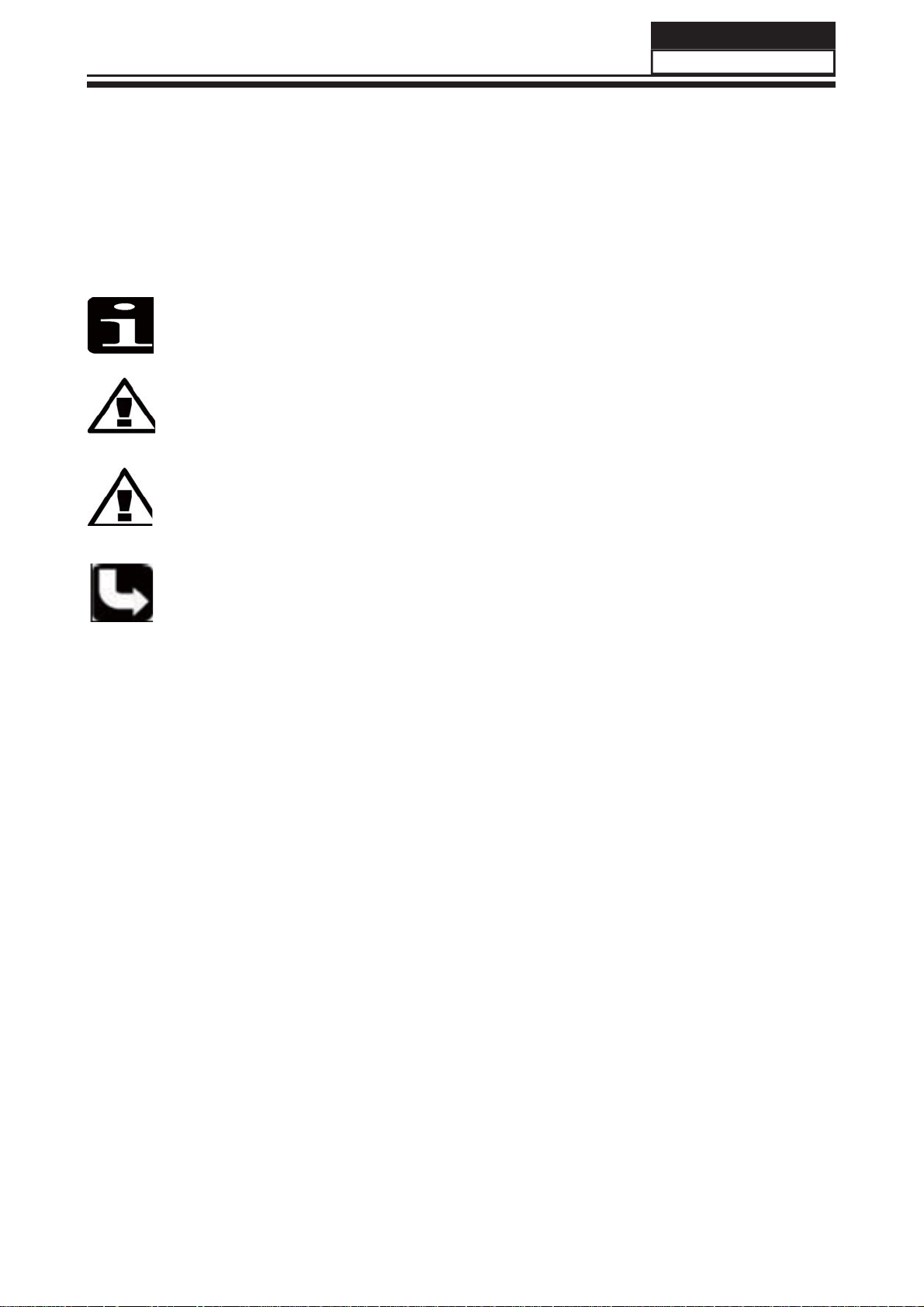
2-2. External pictures (four faces)
Service Manual
Model No.: LEA40T3
Front Side
Left Side
9
Page 11
Service Manual
Model No.: LEA40T3
Chapter 3. Disassemble and Assemble
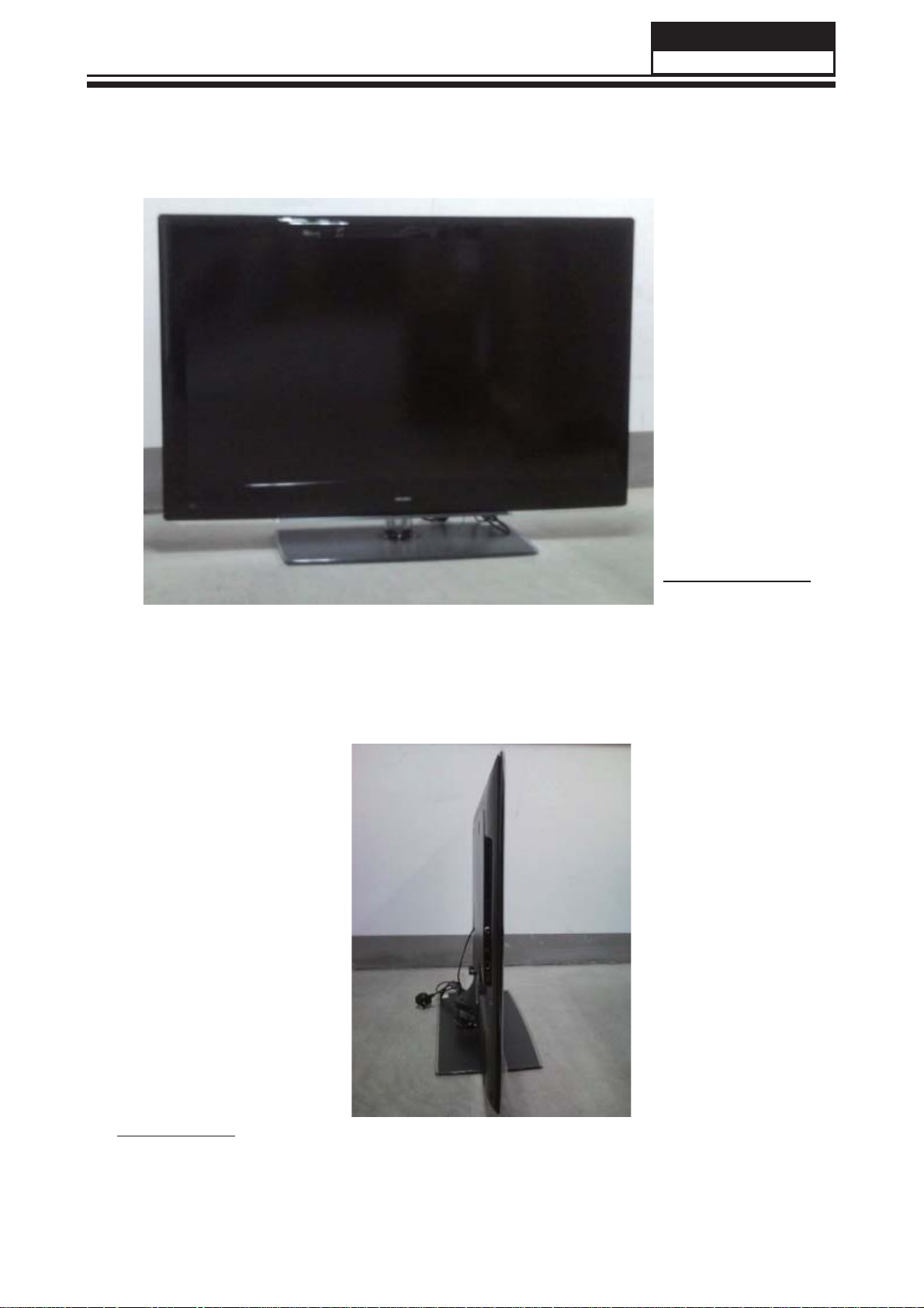
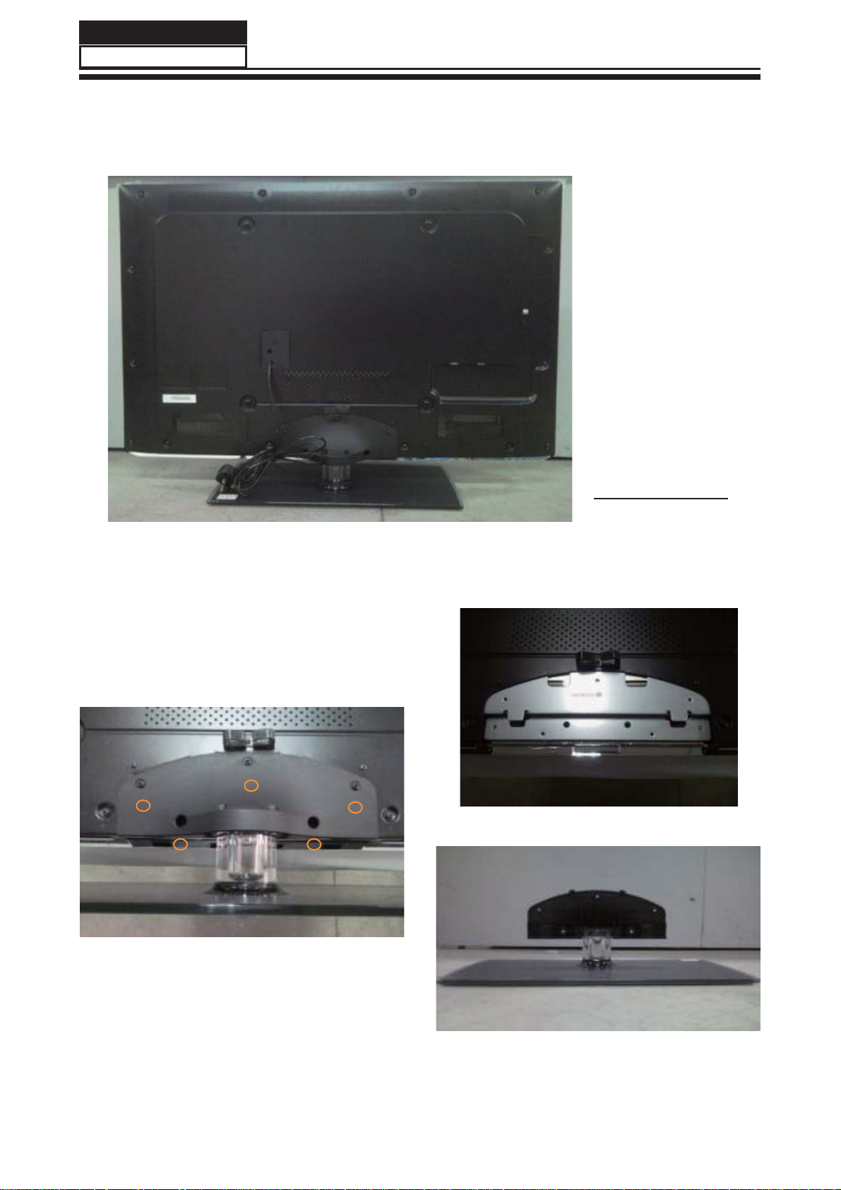
3-1. Remove the Stand
1. Lay down the unit so that back cover faces
upward
Back Side
2. Remove the Five screws from the back
cover which are indicated with the circles in the
picture above.
3. Remove the stand
10
Page 12
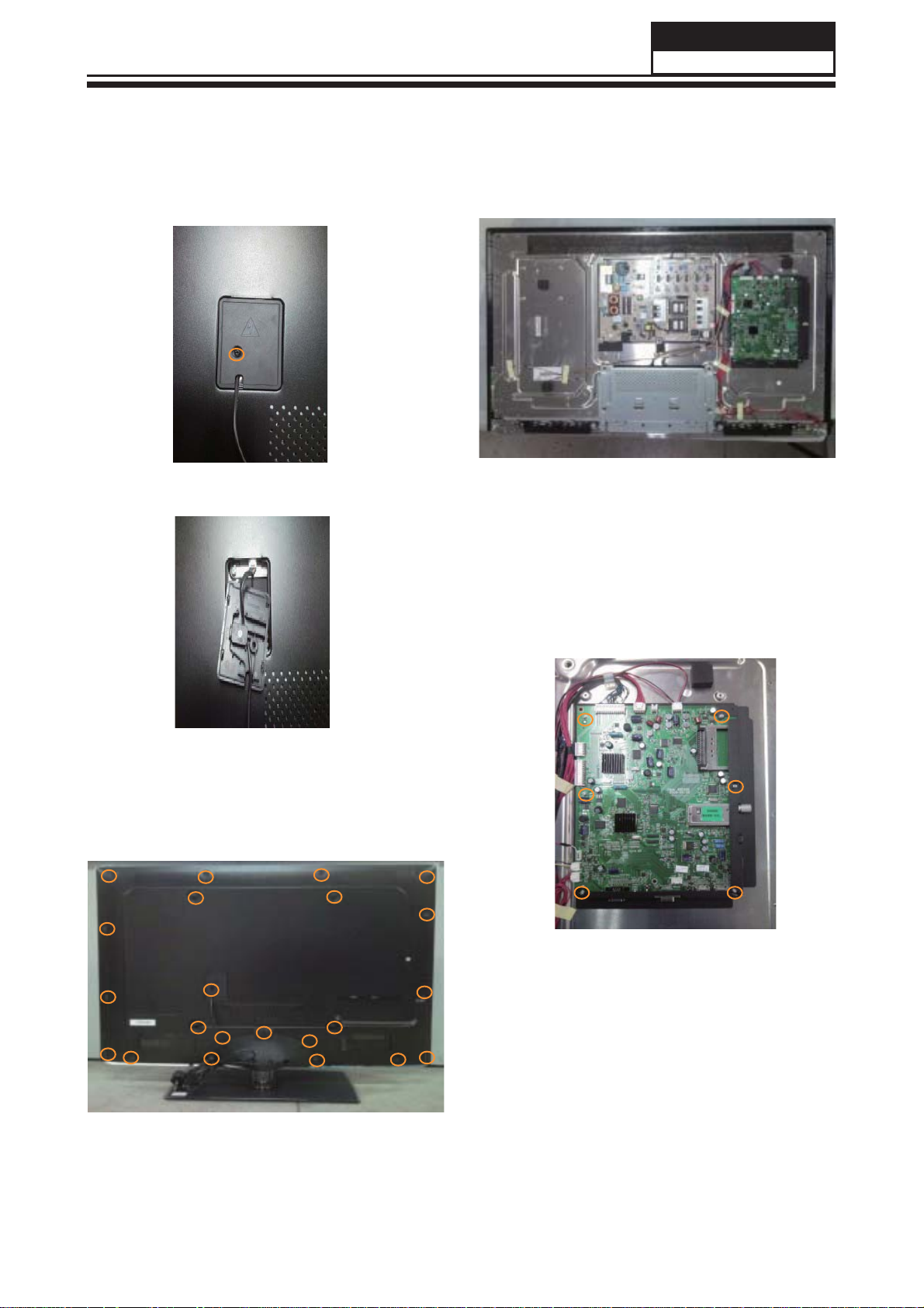
3-2. Remove the Power Cord
Remove the screw indicated by the red
circles in below picture.
Then remove the power cord.
Service Manual
Model No.: LEA40T3
2. Then remove the back cover from the
unit.
3-3. Remove the Back Cover
1. Remove the twenty-two screws indicated
by the red circles in below picture.
3-4. Remove the Mainboard
Remove the five screws indicated by the red
circles in below picture.
Then remove the mainboard.
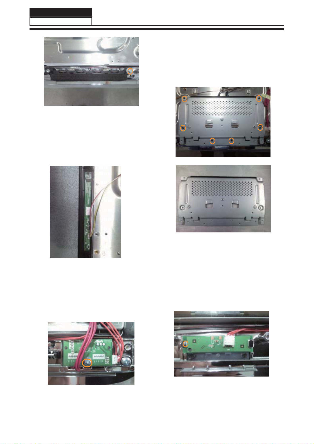
3-5. Remove the speaker
Remove the screw indicated by the red
circles in below picture.
Then remove the speaker.
11
Page 13
Service Manual
Model No.: LEA40T3
3-6. Remove the Keypad
The Keypad is conglutinated with front frame
, just uncover the keypad gently.
Then remove the keypad.
3-8. Remove the Stand backstop
Remove the six screws indicated by the red
circles in below picture.
Take out the stand backstop.
3-7. Remove the Remote Control
Board
Remove the screw indicated by the red
circles in below picture.
Take out the remote control board.
3-9. Remove the indicator light
The indicator light is buckled into the front
frame,remove the clasp indicated by the red
circles in below picture.
Take out the indicator light.
12
Page 14
Service Manual
Model No.: LEA40T3
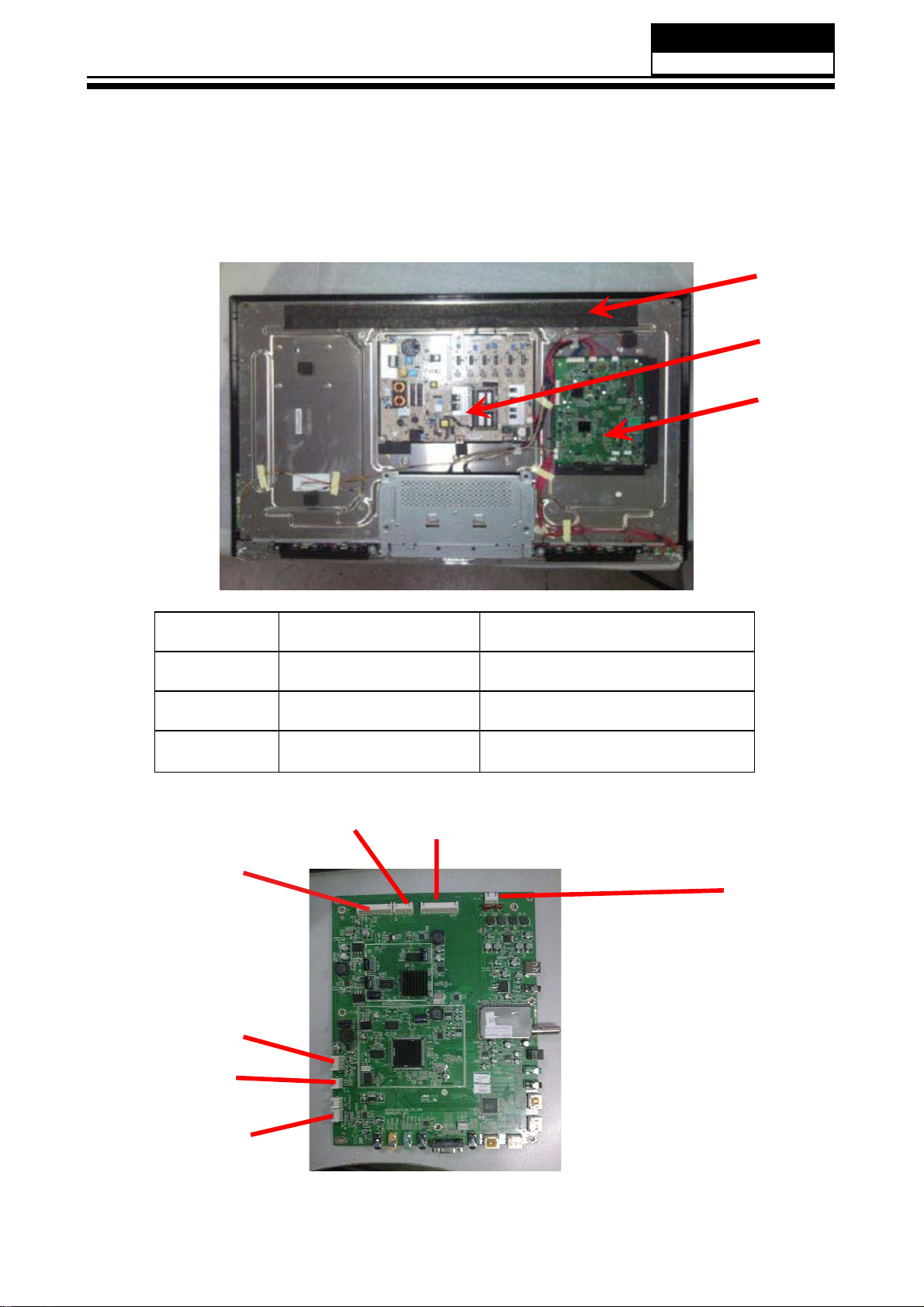
Chapter 4. Location of Controls and Components
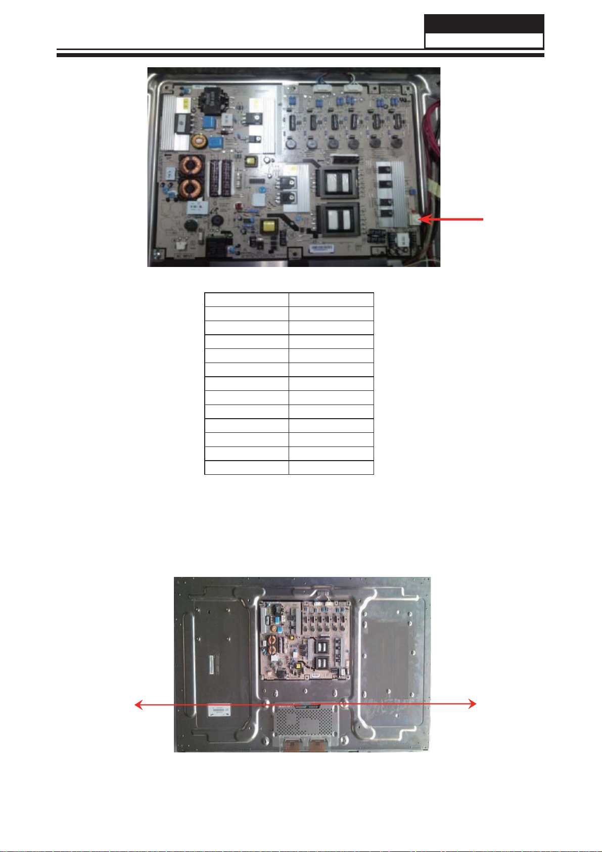
4-1. Board Location
A
B
C
No. Parts number Description
A Board CPANEL
B Board /Power Board
C Board MMainboard
4-2. Main Board
CND3
CNA1
CNE2
CND4
CND5
CON2
CNE1
13
Page 15
Service Manual
Model No.: LEA46T3
4-2-1. Function Description:
Main Board
Process signal which incept from exterior equipment then translate into signal that panel can display.
4-2-2. Connector defi nition
Main board connector
Speaker connector (CON2)
Pin number Signal name
1 LOUT+
2 LOUT3 ROUT4 ROUT+
12V/5V Connector (CNA1)
Pin number Signal name
1 +12V
2 +12V
3 GND
4 +12V
5 GND
6 GND
7 5VSTB
8/
9 GND
10 PW-ON/OFF
11 PB-ADJUS
12 PB-ON/OFF
Keypad Connector (CNE2)
Pin number Signal name
1 GND
2 KEY1
3 KEY0
4 3.3VS
Rom connector (CNE1)
Pin number Signal name
1 5VS
2IR
3 LED-R
4 LED-G
5 GND
4-3. Power Supply Board
4-3-1. Function description:
To supply power for Mainboard, Panel.
4-3-2. Connector defi nition:
INPUT CONNECTOR (CN10)
14
Page 16
Service Manual
Model No.: LEA40T3
Pin number Signal name
1 +12V
2 +12V
3 GND
4 +12V
5 GND
6 GND
7 +5VSB
8 EXT_DIM
9 GND
10 PS-ON
11 INT_DIM
12 BL_ON
CNM801
4-4. LCD Panel
CN2
CN1
15
Page 17

Service Manual
Model No.: LEA40T3
4-4-1. Function Description: Display the signal.
4-4-2. Connector defi nition:
CN1 Connector
Pin number Symbol Description
1 12V DC Power Supply
2 12V DC Power Supply
3 12V DC Power Supply
4 12V DC Power Supply
5 12V DC Power Supply
6NC NC
7 GND Ground
8 GND Ground
9 GND Ground
st ,5th
10 Rx1[0]N 1
11 Rx1[0]P 1
12 Rx1[1]N 1
13 Rx1[1]P 1
14 Rx1[2]N 1
15 Rx1[2]P 1
LVDS Signal -
st ,5th
LVDS Signal +
st ,5th
LVDS Signal -
st ,5th
LVDS Signal +
st ,5th
LVDS Signal -
st ,5th
LVDS Signal +
16 GND Ground
st ,5th
17 Rx1CLK- 1
18 Rx1CLK+ 1
LVDS Clock -
st ,5th
LVDS Clock +
16
19 GND Ground
st ,5th
20 Rx1[3]N 1
21 Rx1[3]P 1
22 Rx1[4]N 1
23 Rx1[4]P 1
LVDS Signal -
st ,5th
LVDS Signal +
st ,5th
LVDS Signal -
st ,5th
LVDS Signal +
24 GND Ground
Page 18

Pin number Symbol Description
Service Manual
Model No.: LEA40T3
25 Rx3[0]N 3
26 Rx3[0]P 3
27 Rx3[1]N 3
28 Rx3[1]P 3
29 Rx3[2]N 3
30 Rx3[2]P 3
rd,7th
LVDS Signal -
rd,7th
LVDS Signal +
rd,7th
LVDS Signal -
rd,7th
LVDS Signal +
rd,7th
LVDS Signal -
rd,7th
LVDS Signal +
31 GND Ground
rd,7th
32 Rx3CLK- 3
33 Rx3CLK+ 3
LVDS Clock -
rd,7th
LVDS Clock +
34 GND Ground
rd,7th
35 Rx3[3]N 3
36 Rx3[3]P 3
LVDS Signal -
rd,7th
LVDS Signal +
rd,7th
37 Rx3[4]N 3
38 Rx3[4]P 3
LVDS Signal -
rd,7th
LVDS Signal +
39 GND Ground
40 NC NC
41 NC NC
17
Page 19

Service Manual
Model No.: LEA40T3
CN2 Connector
Pin number Symbol Description
1 12V DC Power Supply
2 12V DC Power Supply
3 12V DC Power Supply
4 12V DC Power Supply
5 12V DC Power Supply
6NC NC
7 GND Ground
8 GND Ground
9 GND Ground
nd ,6th
10 Rx2[0]N 2
11 Rx2[0]P 2
12 Rx2[1]N 2
13 Rx2[1]P 2
14 Rx2[2]N 2
15 Rx2[2]P 2
nd ,6th
nd ,6th
LVDS Signal -
LVDS Signal +
nd ,6th
LVDS Signal -
nd ,6th
LVDS Signal +
nd ,6th
LVDS Signal -
LVDS Signal +
16 GND Ground
nd ,6th
17 Rx2CLK- 2
18 Rx2CLK+ 2
nd ,6th
LVDS Clock -
LVDS Clock +
19 GND Ground
20 Rx2[3]N 2
nd ,6th
LVDS Signal -
18
21 Rx2[3]P 2
22 Rx2[4]N 2
23 Rx2[4]P 2
nd ,6th
LVDS Signal +
nd ,6th
LVDS Signal -
nd ,6th
LVDS Signal +
24 GND Ground
25 Rx4[0]N 4
26 Rx4[0]P 4
27 Rx4[1]N 4
th,8th
LVDS Signal -
th,8th
LVDS Signal +
th,8th
LVDS Signal -
Page 20

Pin number Symbol Description
Service Manual
Model No.: LEA40T3
28 Rx4[1]P 4
29 Rx4[2]N 4
30 Rx4[2]P 4
th,8th
LVDS Signal +
th,8th
LVDS Signal -
th,8th
LVDS Signal +
31 GND Ground
th,8th
32 Rx4CLK- 4
33 Rx4CLK+ 4
LVDS Clock -
th,8th
LVDS Clock +
34 GND Ground
35 Rx4[3]N 4
36 Rx4[3]P 4
37 Rx4[4]N 4
38 Rx4[4]P 4
th,8th
LVDS Signal -
th,8th
LVDS Signal +
th,8th
LVDS Signal -
th,8th
LVDS Signal +
39 GND Ground
40 NC NC
41 NC NC
42 NC NC
43 NC NC
44 NC NC
45 LVDS_SEL
HIGH (3.3V) Normal LVDS Format
LOW (GND) JEIDA LVDS Format
46 NC NC
47 NC NC
48 NC NC
49 NC NC
50 NC NC
51 NC NC
19
Page 21
Service Manual
Model No.: LET40T3
Chapter 5. Installation Instructions
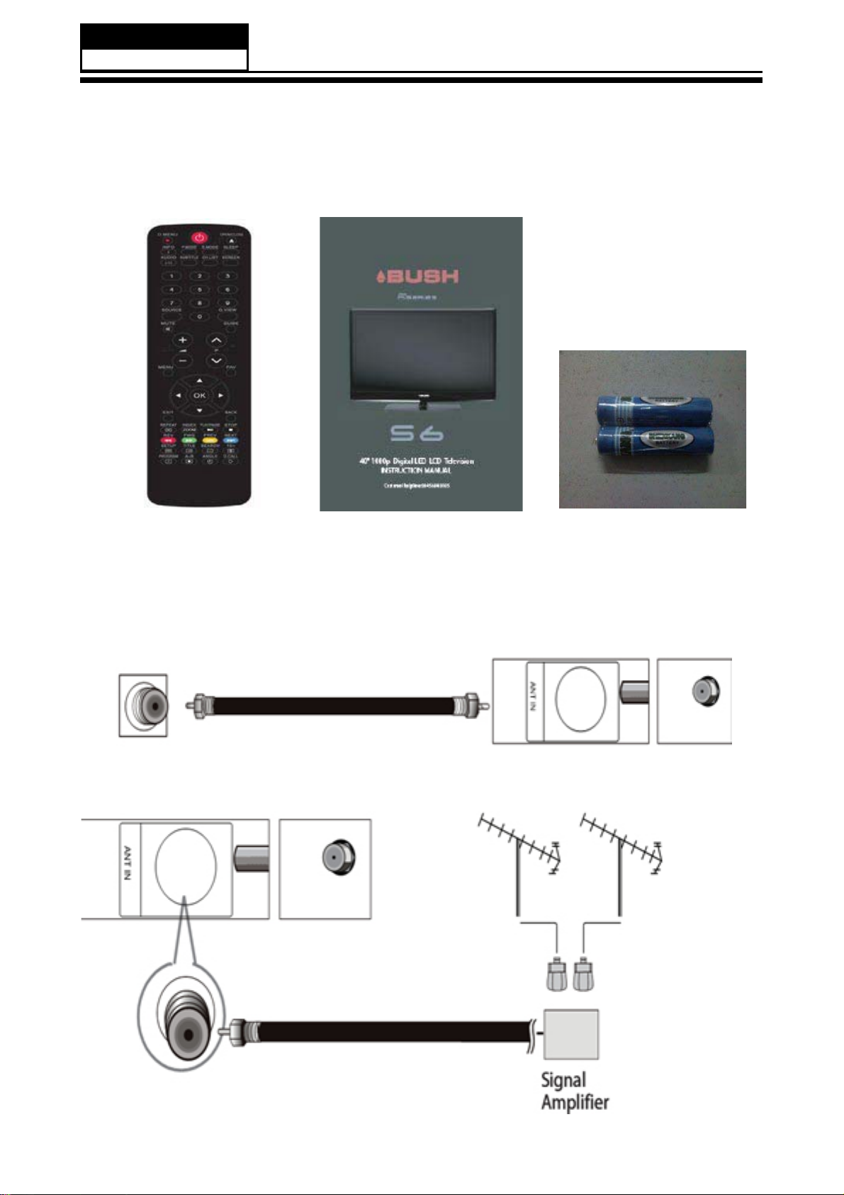
5-1. External Equipment Connections
Accessories
Remote Control
Antenna Connection:
Connect one end of a coaxial cable (not included) to the ANT IN jack on the back of your TV/DVD
combo, then connect the other end of the cable into the antenna or cable TV wall outlet.
7RLPSURYHSLFWXUHTXDOLW\IURPDQDQWHQQDLQDSRRUVLJQDODUHDLQVWDOODVLJQDODPSOL¿HU
User's Guide
Batteries
20
Page 22

Service Manual
Model No.: LET40T3
If you need to split the antenna signal to connect two TVs, install a two-way splitter.
Choose Your Connection
There are several ways to connect your television, depending on the components you want to
FRQQHFWDQGWKHTXDOLW\RIWKHVLJQDO\RXZDQWWRDFKLHYH7KHIROORZLQJDUHH[DPSOHVRIVRPH
different ways to connect your TV with different input sources. Choose the connection which is best
for you.
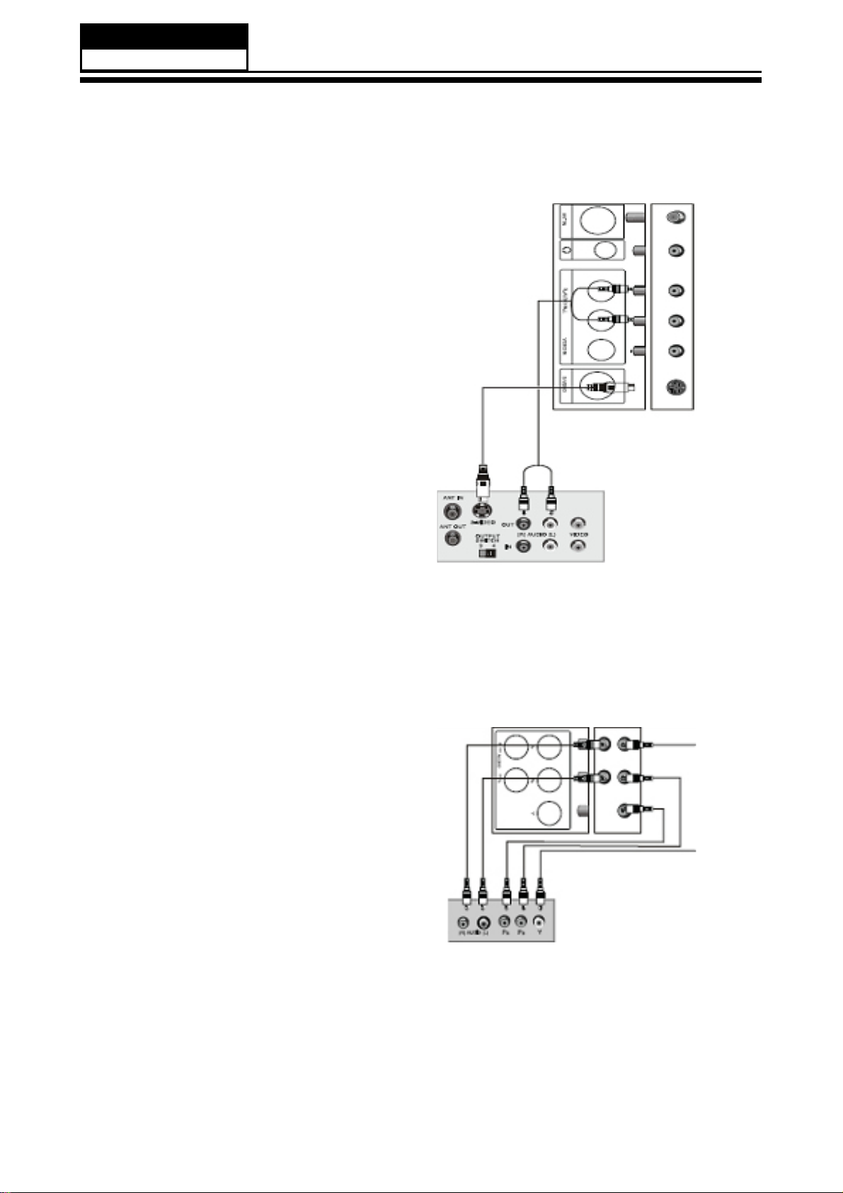
VCR connection
Connecting a VCR with a standard AV cable.
A standard AV connection provides good
video and audio.
To connect a VCR with a standard AV cable:
1 Make sure that your TV/DVD combo and
the VCR are turned off;
2 Connect a standard AV cable(not included)
to the VIDEO IN (yellow) and adjust R (red)
and L (white) AUDIO jacks on the back of your
TV/DVD combo, then connect the other end of
the cable to the VIDEO and AUDIO OUT jacks
on the VCR;
3 Turn on your TV/DVD combo and the VCR;
4 Press INPUT, press CH+ or CH- to select
VEDIO, then press ENTER.
21
Page 23
Service Manual
Model No.: LET40T3
Connecting a VCR with an S-Video cable
An S-Video connection provides better video
than a standard AV connection.
To connect a VCR with an S-Video cable:
1. Make sure that your TV/DVD combo and
the VCR are turned off;
2. Connect an S-Video cable(not included)
to the S-VIDEO jack on the back of your TV/
DVD combo,then connect the other end of the
S-VIDEO OUT jack on the VCR;
3. Connect a standard audio cable(not
included)to the R and L AUDIO jacks to the
left of the VIDEO jack on the back of your TV/
DVD combo,them connect the other end of the
cable to the AUDIO OUT jacks on the VCR;
4. Turn on your TV/DVD combo and the VCR;
5. Press INPUT,press CN+ or CN- to select
S-VIDEO,then press ENTER.
External Equipment Connections: Connecting a component
video device
A component video device provides better
video than an S-Video connection.
To connect a component video device.
1. Make sure that your TV/DVD combo and
the component video device are turned off;
2. Connect a component video cable not
included to the Pr,Pb,and V jades on the back
of your TV/DVD combo,then connect the
other end of the cable to the corresponding
COMPONENT OUT jacks on the component
video device;
3. Connect a standard audio cable(not
included) to the R and L AUDIO jacks below the
Pr,Pb,and Y jacks on the back of your TV/DVD
combo,then connect the other end of the cable
to the COMPONENT AUDIO OUT jacks on the
VCR;
4. Turn on your TV/DVD combo and the
component video device;
5. Press INPUT,press CH+ or CH- to seclect
COMPONENT,then press ENTER.
22
Page 24

Chapter 6. Operation Instructions
6-1. Front Panel Controls
Service Manual
Model No.: LEA32T3
23
Page 25

Service Manual
Model No.: LEA32T3
6-2. Back Panel Controls
24
Page 26

Service Manual
Model No.: LEA32T3
6-3 Setting Up Your Remote Control
After being setting up properly, your remote control can operate in six different modes:
TV, VCR, CABLE, DVD, SETBOX or AUDIO.
Pressing the corresponding button on the remote control allows you to switch between these modes,
DQGFRQWUROZKLFKHYHUSLHFHRIHTXLSPHQW\RXFKRRVH
Note:
The remote control might not be compatible with all DVD Players, VCRs and Cable boxes.
25
Page 27

Service Manual
Model No.: LEA32T3
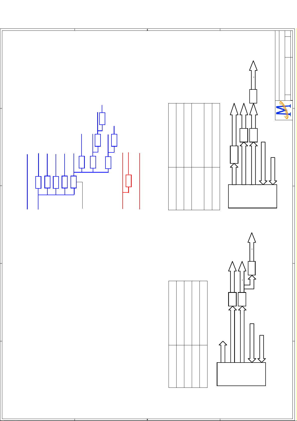
Chapter 7. Electrical Parts
7-1. Block Diagram
26
Page 28
V1
V1
V1
Rev
Rev
Rev
of
of
of
215Friday, December 04, 2009
215Friday, December 04, 2009
215Friday, December 04, 2009
By Ray
Drawn
Drawn
Drawn
E
HeadPhoneTDA1308
MEM_REF
TEL:(03)567-0766 FAX:(03)578-7610
No.1-2, Innovation Rd 1, SBIP, Hsin-Chu City 300
TEL:(03)567-0766 FAX:(03)578-7610
No.1-2, Innovation Rd 1, SBIP, Hsin-Chu City 300
TEL:(03)567-0766 FAX:(03)578-7610
No.1-2, Innovation Rd 1, SBIP, Hsin-Chu City 300
MediaTek Confidential
MediaTek Confidential
MediaTek Confidential
MediaTek Inc.
MediaTek Inc.
MediaTek Inc.
E
MT5305A P1V1
MT5305A P1V1
MT5305A P1V1
Placement/SYS Flow
Placement/SYS Flow
Placement/SYS Flow
Document Number
Document Number
Document Number
Date: Sheet
Date: Sheet
Date: Sheet
Size
Size
Size
Title
Title
Title
C
C
C
DDRV
1/2
AV125
USB_5V
DV33
AV33
LDO
LDO
+5VSB
+5VSB
+3VSB
LDO
POWER ON
POWER ON
AIN6
Audio Mapping
Source
AV1
D
TCON 12V
VCCK
+24V AMP
Tuner_5V
(DELAY 1MS THAN VCCK)
DVD_5V(OPTION)
+5V
MOSFET
DC+24V
MOSFET
DC+12V
DC/DC
7805
DC/DC
DC/DC
VCCK CONTROL
LDO
LDO
2:1
}
AIN3
AIN4
2:1
}
YPBPR#2
YPBPR#1
INNER_DVD
AIN0
S-VIDEO
AV2
AIN5
VGA/DVI
R/L Line out
LM4558
Speaker
Speaker Amp.
TPS5708
PWM AR/L0
I2S
LM4558
PWM AR/L1
MT5305A
D
ADC_IN R/L x 5
Tuner MPX/IF+/-
For 32"/37"/42" model 5×AUDIO IN:
C
Audio System
HeadPhoneTDA1308
C
DELETE S_VIDEO
R/L Line out
Speaker
B
AIN4
AIN6
AIN3
AIN5
LM4558
LM4558
B
Audio Mapping
NC
PWM AR/L0
PWM AR/L1
ADC_IN R/L x 4
I2S
Tuner MPX/IF+/-
AV1
A
Source
INNER_DVD
YPBPR#1
VGA/DVI
MT5305A
A
For 19"/22"/24" model 4×AUDIO IN:
4 4
3 3
2 2
1 1
Page 29

Rev
Rev
Rev
of
of
of
25Friday, November 27, 2009
25Friday, November 27, 2009
25Friday, November 27, 2009
Drawn
Drawn
Drawn
1
+12V
AM81_DV10 3
AM81_AV33 3,5
AM81_AV33
AM81_AV12 3,4,5
AM81_AV12
AM81_AV12
AM81_DV33 3,4
AM81_DV33
AM81_DV33
AM81_AV33
2
2
4
AEMC1
EMC/NC
AEMC1
EMC/NC
1
3
3
GND 3,4,5
GND
AM81_DV10
AM81_DV10
Add 09.03.02
AM81_DV10
+12V3,10,11,12,13
AC220
0.1uF
AC220
0.1uF
ACE85
100uF/10V Low ESR
ACE85
100uF/10V Low ESR
+
+
AR264
5.1K_1%
R0603/SMD
AR264
5.1K_1%
R0603/SMD
AR268
AR268
27K_1%
R0603/SMD
27K_1%
R0603/SMD
MT8281 AV33MT8281 DV33
AM81_DV33 AM81_AV33
AM81_DV33
AFB75
AFB75
Vout=0.925 x (1+Rup/Rdn) = 1.1V/0.9A
AV33/0.22A
80 R/100mHz
80 R/100mHz
ACE638
ACE638
AR1869
12K
AR1869
12K
AC993
1uF
AC993
1uF
AC226
10uF/0805
AC226
10uF/0805
ACE637
ACE637
+
+
220uF/16v/NC
220uF/16v/NC
+
+
220uF/10v
220uF/10v
AR1870
4.7K
AR1870
4.7K
AC992
AC992
ACB621
0.1uF
ACB621
0.1uF
ACB626
ACB626
0.1uF
0.1uF
0.01uF
0.01uF
2009071320090713
GND
AV12/65mA
AU61
AU61
MT8281 AV33 MT8281 AV12
Vout=0.925 x (1+Rup/Rdn) =3.3V/1.2A
ACB623
ACB623
ACE639
+
AC989
AC989
AR1828
NS/100
AR1828
NS/100
2
OUT
AX1212/AP1122
AX1212/AP1122
GND
1
IN
3
ACB622
ACB622
ACE641
ACE641
+
+
AM81_AV33 AM81_AV12
0.1uF
0.1uF
10uF/10v+ACE639
10uF/10v
1uF
1uF
0.1uF
0.1uF
47uF/16v /NC
47uF/16v /NC
AR18300AR1830
0
TEL:(03)567-0766 FAX:(03)578-7610
No.1-2, Innovation Rd 1, SBIP, Hsin-Chu City 300
TEL:(03)567-0766 FAX:(03)578-7610
No.1-2, Innovation Rd 1, SBIP, Hsin-Chu City 300
TEL:(03)567-0766 FAX:(03)578-7610
No.1-2, Innovation Rd 1, SBIP, Hsin-Chu City 300
MediaTek Confidential
MediaTek Confidential
MediaTek Confidential
MediaTek Inc.
MediaTek Inc.
MediaTek Inc.
Title
Title
Title
Power
Power
Power
1
MT8281_D2V1
MT8281_D2V1
MT8281_D2V1
Document Number
Document Number
Document Number
C
C
C
Date: Sheet
Date: Sheet
Date: Sheet
Size
Size
Size
2
3
AC224
AC224
AU23
AU23
10nF
10nF
1
MP1482
MP1482
2
AR1833
AR1833
AL28 10uH/3AAL28 10uH/3A
3
BS
IN
100K
100K
1 2
SW
MPS1482
MPS1482
EN7SS
10uH/3A
10uH/3A
AD13
B340/NC
AD13
B340/NC
FB
5
FB
8
COMP
GND
ACB442
ACB442
AR265
2.2K
AR265
2.2K
6
AC223
10nF
AC223
4
0.1uF
0.1uF
10nF
AU65
AU65
AL29
AL29
3
MP1482
MP1482
2
C28
10nF
C28
10nF
1
5
FB
BST
OUT
EN
VCC
7
6
GND
SS8COMP
4
C26
0.1uF
C26
0.1uF
4
4
Core Power 1.1V
LDO#3 5V to MT5307 DV33
C27
C27
10nF
10nF
2.2K
AC222
0.1uF
AC222
0.1uF
AFB86
AFB86
20090713
80 R/100mHz
+12V
80 R/100mHz
+
+
ACE84
ACE84
47uF/16V
47uF/16V
C C
5
D D
+12V
AFB87
AFB87
AR1867
AR1867
80 R/100mHz
80 R/100mHz
100K
100K
ACB625
0.1uF
ACB625
0.1uF
+
+
ACE86
ACE86
20090713
47uF/16V
47uF/16V
2.2K
AR1868
AR1868
5
B B
A A
Page 30

V1
V1
V1
Rev
Rev
Rev
of
of
of
315Friday, December 04, 2009
315Friday, December 04, 2009
315Friday, December 04, 2009
By Ray
Drawn
Drawn
Drawn
E
D
C
AV33
AV125
+3V3SB
+5VSB
GND
DV33
+5V
AV334,6,8,9,10,12,13
AV1254,5,8,9,12
+5VSB6,9,14
+3V3SB6,8,9,12
GND4,5,6,7,8,9,10,11,12,13,14
DV334,5,6,7,11,12
+5V6,8,10,12,14
+12V
VCCK
+12V10,11,12,13,14
VCCK4
SPC10
0.1uF
SPC10
AV33+5V
SPU2 AX1117EJ/adjSPU2 AX1117EJ/adj
ANALOG POWER AV33
0.1uF
SPC9
1uF
SPC9
1uF
SPFB2 0SPFB2 0
SPC8
47uF/16v+SPC8
47uF/16v
+
SPR2
110_1%
R0603/SMD
SPR2
110_1%
R0603/SMD
SPR4
180_1%
R0603/SMD
SPR4
180_1%
R0603/SMD
2
OUT
ADJ/GND
1
IN
3
SPC7
0.1uF
SPC7
0.1uF
SPC6
47uF/16v+SPC6
47uF/16v
+
1.25 x (1+180/110) = 3.3V
SPC21
NS/1uF
SPC21
NS/1uF
SPC20
0.1uF
SPC20
0.1uF
SPC19
47uF/16v+SPC19
47uF/16v
+
SPR7
100_1%/NC
R0603/SMD
SPR7
100_1%/NC
R0603/SMD
2
OUT
AX1117EJ/adj
AX1117EJ/adj
GND
1
IN
SPU4
SPU4
3
SPC18
0.1uF
SPC18
0.1uF
SPC17
NS/47uF/16v
SPC17
NS/47uF/16v
+
+
AV33 AV125
Modify 09.06.19
SPR90R0603/SMD
SPR90R0603/SMD
TEL:(03)567-0766 FAX:(03)578-7610
No.1-2, Innovation Rd 1, SBIP, Hsin-Chu City 300
TEL:(03)567-0766 FAX:(03)578-7610
No.1-2, Innovation Rd 1, SBIP, Hsin-Chu City 300
TEL:(03)567-0766 FAX:(03)578-7610
No.1-2, Innovation Rd 1, SBIP, Hsin-Chu City 300
MediaTek Confidential
MediaTek Confidential
MediaTek Confidential
MediaTek Inc.
MediaTek Inc.
MediaTek Inc.
2A
0.01uF
0.01uF
CPC43
CPC43
0.1uF
0.1uF
CPC39
CPC39
1uF
1uF
CPC42
CPC42
+
CPC40
470uF/16v+CPC40
470uF/16v
CPR13 0CPR13 0
R6
R6
5.1K_1%
5.1K_1%
R0603/SMD
R0603/SMD
R11
R11
27K_1%
R0603/SMD
27K_1%
R0603/SMD
E
Digital/Analog POWER
Digital/Analog POWER
Digital/Analog POWER
MT5305A P1V1
MT5305A P1V1
MT5305A P1V1
Document Number
Document Number
Document Number
C
C
C
Date: Sheet
Date: Sheet
Date: Sheet
Size
Size
Size
Title
Title
Title
D
C
0.925 x (1+Rup/Rdn) = 1.1V
B
Stand By Power
A
+5VSB
4 4
+3V3SB
+3V3SB
SPU1 G1117/adjSPU1 G1117/adj
SPC5
NS/0.1uF
SPC5
NS/0.1uF
SPC13
0.1uF
SPC13
0.1uF
SPC4
1uF
SPC4
1uF
SPC3
47uF/16v+SPC3
47uF/16v
+
1.25 x (1+180/110) = 3.3V
SPR3
180_1%
R0603/SMD
SPR3
180_1%
1
110_1%
110_1%
SPC2
SPC2
SPC1
R0603/SMD
R0603/SMD
NS/0.1uF
NS/0.1uF
47uF/16v+SPC1
47uF/16v
R0603/SMD
SPR1
SPR1
2
OUT
ADJ/GND
IN
3
+
DV33+5V
SPC12
1uF
SPC12
1uF
DV33
SPC15
47uF/16v+SPC15
47uF/16v
+
SPR5
110_1%
R0603/SMD
SPR5
110_1%
R0603/SMD
2
OUT
ADJ/GND
1
DIGITAL POWER DV33 ANALOG POWER AV125
IN
SPU3 AP1084-ADJSPU3 AP1084-ADJ
3
SPC11
0.1uF
SPC11
0.1uF
SPC14
47uF/16v+SPC14
47uF/16v
+
3 3
SPR6
SPR6
180_1%
R0603/SMD
180_1%
R0603/SMD
1.25 x (1+180/110) = 3.3V
1 2
L5 10uH/3AL5 10uH/3A
D10
B340/NC
D10
B340/NC
C23
10nF
C23
10nF
1
3
BST
OUT
U60
MP1484
U60
MP1484
EN
VCC
SS8COMP
7
2
6
C6
10nFC610nF
R88 100KR88 100K
CORE POWER
+12V VCCK
2 2
shielding of 20-mil GND
5
FB
GND
4
C22
0.1uF
C22
0.1uF
R12
2.2K
R12
2.2K
C15
0.1uF
C15
0.1uF
+
+
XC14
XC14
220uF/16v
220uF/16v
1 1
B
A
Page 31

Rev
Rev
Rev
of
of
of
35Friday, December 04, 2009
35Friday, December 04, 2009
AM81_DV33 2,4
AM81_AV33 2,5
AM81_AV12 2,4,5
AM81_DV10 2
GND 2,4,5
AC999
0.1uF
AC999
AV33_XTAL
AFB77
AFB77
AM81_AV33
AC998
AC998
0603_Bead
0603_Bead
0.1uF
4.7uF/10V
4.7uF/10V
AV12 PLL POWER
AM81_DV33
AM81_DV33
AM81_AV33
AM81_AV33
AM81_AV12
1
AM81_AV12
AM81_DV10
AM81_DV10
GND
OSDA0
OSCL0
LVDS_CTRL2
OSDA04
LVDS_CTRL2
AR1844 100AR1844 100
AR1842 0AR1842 0
AR1843 100AR1843 100
OSCL04
M81_RST# LVDS_CTRL2
Modify 09.09.08
M81_SDA OSDA0
M81_SCL OSCL0
AM81_AV33
Reserve HW Reset#
AR1838
4.7K
AR1838
4.7K
ACE37
ACE37
220uF/16V/NC
220uF/16V/NC
+
+
M81_RST#
AQ1
AQ1
2N3904/NC
2N3904/NC
1
1K/NC
1K/NC
AR21
AR21
AC290
AC290
3 2
AR22
AR22
AD1
AD1
0.47uF/NC
0.47uF/NC
47K/NC
47K/NC
1N4148/NC
1N4148/NC
Modify 09.02.26
AV33 XTAL POWER
AV12_PLL
AFB78
AFB78
AM81_AV12
AC1004
AC1004
AC1003
AC1003
AC1002
AC1002
0603_Bead
0603_Bead
AC923
AC923
330pF
330pF
0.1uF
0.1uF
4.7uF/10V
4.7uF/10V
4.7uF/10V
4.7uF/10V
No.1-2, Innovation Rd 1, SBIP, Hsin-Chu City 300
No.1-2, Innovation Rd 1, SBIP, Hsin-Chu City 300
No.1-2, Innovation Rd 1, SBIP, Hsin-Chu City 300
MediaTek Confidential
MediaTek Confidential
MediaTek Confidential
35Friday, December 04, 2009
Max
Drawn
Drawn
Drawn
Peripheral
Peripheral
Peripheral
Title
Title
Title
1
MT8281_D2V1
MT8281_D2V1
MT8281_D2V1
Document Number
Document Number
Document Number
C
C
C
Date: Sheet
Date: Sheet
Date: Sheet
Size
Size
Size
TEL:(03)567-0766 FAX:(03)578-7610
TEL:(03)567-0766 FAX:(03)578-7610
TEL:(03)567-0766 FAX:(03)578-7610
MediaTek Inc.
MediaTek Inc.
MediaTek Inc.
AC1052
AM81_DV10
AC1052
1.5nF
1.5nF
AC1044
AC1044
330pF
330pF
AC1051
AC1051
1.5nF
1.5nF
AC1043
AC1043
AC1045
AC1045
AC1042
AC1042
AC1040
AC1040
AC1039
AC1039
AC921
AC921
AC922
AC922
+
ACE634
100uF/10V+ACE634
100uF/10V
1.5nF
1.5nF
0.01uF
0.01uF
0.01uF
0.01uF
0.1uF
0.1uF
0.1uF
0.1uF
4.7uF/10V
4.7uF/10V
22uF/10V->10uF
22uF/10V->10uF
PIN4. PWR
PIN3. RXD
PIN2. TXD
PIN1. GND
2
AJ30
AJ30
123
4
4x1 W/HOUSING
4x1 W/HOUSING
AM81_AV33
AR1841
4.7K
AR1841
modify net for layout 09/02/20
4.7K
AR1839
4.7K
AR1839
4.7K
Crystal
M81_U0RX
ACE643
ACE643
+
+
ACB624
0.1uF
ACB624
0.1uF
M81SPI_SO
M81SPI_SCK
7
6
5
CLK
VCC
HOLD#
CS#1DOUT2WP#/VPP3VSS
4
M81SPI_SI
WP#
10uF/10v/NC
10uF/10v/NC
DIN
M25P08
M25P08
M81_U0TX
Add 09.03.05
ATP26ATP26
ATP25ATP25
M81SPI_SCK
M81SPI_SO
M81_JTDO
1K
AR18521KAR1852
AM81_DV33
Trapping :
Default Low when no configuration external
1st UART IF
( For Code download and Debug )
3
AM81_DV33
8
AU63
AU63
M81SPI_CS#
AR18371KAR1837
1K
4
Serial Flash
AM81_DV33
ARB1 820K->1MARB1 820K->1M
AY6
AY6
XTALI XTALO
AC997
30pF
AC997
30pF
Hosonic-27MHz
Hosonic-27MHz
AC996
30pF
AC996
30pF
Modify for accuracy
DV33 IO POWER
AM81_DV33
AC1038
4.7nF
AC1038
4.7nF
AC1037
4.7nF
AC1037
4.7nF
AC1036
0.1uF
AC1036
0.1uF
AC1035
0.1uF
AC1035
0.1uF
AC1001
4.7uF/10V
AC1001
4.7uF/10V
ACE645
100uF/10v/NC
ACE645
100uF/10v/NC
+
+
DV10 CORE POWER
Add 09.02.25
2
3
4
AR18400AR1840
0
Add res, 09.04.10
M81SPI_CS#
M81SPI_SCK
M81SPI_SI
M81SPI_SO
M81_JTDO
M81_RST#
U3
W16
U4
U2
V2
V1
JTDI
AU60C
AU60C
JRTCK
5
AVDD33_XTAL
V20
AV33_XTAL
Peripheral components
T5
JTCK
JTMS
JTDO
JTRST
CLK_IN
AVDD12_SYSPLL
AVDD12_DMPLL
AVDD12_MJCPLL
U13
U14
U15
AV12_PLL
D D
Y16
CLK_OUT
W2
W1
RXDMA_ACK
Y19
GND
Y3
Y2
GPIO0V3GPIO3
GPIO1
PRST_
EFUSE
AVSS12_SYSPLL
AVSS12_DMPLL
AVSS12_MJCPLL
AVSS33_XTAL
V13
V14
V15
W3
V4
GPIO2
M81_SDA
TP0
Y18
M81_SCL
U11
V11
SDA
TN0
W18
SCL
M81_U0TX
M81_U0RX
W17
Y17
TXD0
RXD0
XTALO
XTALI
W20
W19
XTALO
XTALI
B19
C20
B20
C19
SFD0
SFD1
SFCK
SFCS
MT8282_BGA_20081008_Final
MT8282_BGA_20081008_Final
AM81_DV10
AM81_DV33
Core Powe 1.0V
IO Power 3.3V
C C
AU60A
AU60A
C18
U12
VCC3IO_3
VCC3IO_2
DVSSB2DVSS
C11
T4
VCC3IO_1R5VCC3IO_1
DVSS
DVSS
DVSSC3DVSSC4DVSS
C12
C13
A18
D11
VCCK
A19
A20
VCCK
DVSSD4DVSS
E10
VCCK
B17
VCCK
DVSS
E11
B18
C16
VCCK
VCCK
DVSSE5DVSSE6DVSS
C17
D15
D16
E14
E15
H10
H12
J11
J13
L13
M12
N10
N13
N8
VCCK
VCCK
VCCK
VCCK
VCCK
VCCK
VCCK
VCCK
VCCK
VCCKJ9VCCK
VCCKL8VCCK
VCCKM9VCCK
VCCK
VCCK
DVSS
DVSS
DVSSH5DVSSH9DVSS
DVSS
DVSSJ3DVSSJ5DVSS
DVSS
DVSS
DVSS
DVSSK4DVSSK5DVSSK8DVSSK9DVSS
DVSS
DVSS
DVSSL3DVSSL9DVSS
DVSS
DVSS
DVSSM8DVSS
DVSS
DVSSN3DVSSN9DVSS
DVSSU5DVSS
MT8282_BGA_20081008_Final
MT8282_BGA_20081008_Final
J10
J12
F16
H11
K10
H13
L10
L11
K11
K12
B B
L12
K13
M10
M11
M13
V5
T12
N11
N12
A A
5
Page 32

LVDS
LVDS_CTRL2
LVDS_POWER_ON
TP44TP44
TP43TP43
O0P
O0N
TP_VPLL
LVDS_CTRL1
V1
V1
V1
Rev
Rev
Rev
of
of
of
415Thursday, December 03, 2009
415Thursday, December 03, 2009
415Thursday, December 03, 2009
AVDD33_LVDS
AVDD12_VPLL
DDR2
RCLK1
RCLK1#
RDQS3
RDQS3#
RDQS2
RDQS2#
RDQM2
RDQM3
RWE#
RBA0
RCKE
MEM_VREF3
RBA1
RCAS#
RCS#
RRAS#
RODT
RCLK0#
RCLK0
RDQS1
RDQS1#
RDQS0#
RDQS0
RDQM1
RDQM0
E3P
E3N
ECKP
ECKN
E2P
E2N
E1P
E1N
E0P
E0N
O3P
O3N
OCKP
OCKN
O2P
O2N
O1P
O1N
RA[12..0]
AVDD12_MEMPLL
VCC2IO
HDMI
PWR5V_0
HDMI_SCL0
CEC
AVDD12_HDMI
HDMI_SDA0
HPD_SINK
RX_CB
RX_C
RX_0B
RX_0
RX_1B
RX_1
RX_2B
RX_2
GPIO1
AVDD33_HDMI
AVDD33_DIG
Tuner
TUNER_DATA
IF_AGCT
TUNER_CLK
VIN_ATV
VIP_ATV
AVDD33_SIF
OPWM0
AVDD33_DEMOD1
OPWRSB
ADIN2
OPCTRL3
ADIN5
VCCK
VCC3IO
AV125
Drawn
Drawn
GND
Drawn
1
PERIPHERAL
2
3
Modify 09.06.19Modify 09.06.19
4
LVDS_POWER_ON12
LVDS_CTRL2
USB_PWR_EN0
USB_PWR_ERR0
AVDD33_USB
USB_DM0
USB_DP0
USB_PWR_EN06
USB_PWR_ERR06
USB_DM06
USB_DP06
PDD0
POCE0#
POOE#
GPIO0
JTDO
JTCK
JTRST#
OPWM2
USB_PWR_EN0
USB_DM0
USB_DP0
AVDD33_USB
USB_VRT
VCCK
RX_CB
RX_C
RX_0B
RX_0
RX_1B
RX_1
RX_2B
RX_2
AVDD33_HDMI
AVDD12_HDMI
CEC
HDMI_SCL0
VCCK
HDMI_SDA0
PWR5V_0
HPD_SINK
OPCTRL3
VCCK
OPCTRL2
OPCTRL1
OPCTRL0
OPWRSB
OIRI
U0TX
U0RX
ORESET#
AVDD10_LDO
VSYNC
HSYNC
BP
SOG
GP
COM
RP
SOY1
Y1P
COM1
PB1P
PR1P
SOY0
Y0P
COM0
PB0P
PR0P
AVDD12_RGB
O0N12
O0P12
O1N12
O1P12
O2N12
O2P12
USB_VRT
ASPDIF
OXTALI
OXTALO
AVDD33_XTAL_STB
AVDD33_USB3,6,8,9,10,12,13
USB_VRT6
OXTALO6
OXTALI6
AVDD33_XTAL_STB6
U1
MT5305A_257
U1
MT5305A_257
1
2
3
4
5
6
7
8
9
USB_PWR_ERR0
10
11
12
13
14
15
16
17
18
19
20
21
22
23
24
25
26
27
28
29
30
31
32
33
AVDD33_VGA_STB
34
35
36
37
38
39
40
41
42
43
44
45
AVDD33_VGA_STB
46
47
48
49
50
51
52
53
54
55
56
57
58
59
60
61
62
63
64
MT5305A
MT5305A
MT5305A
Document Number
Document Number
Document Number
Size
Size
Size
Title
Title
Title
CPC65
NS/3300pF
CPC65
NS/3300pF
CPC60
0.1uF
CPC60
0.1uF
CPC63
NS/0.01uF
CPC63
NS/0.01uF
NS/4.7uF/10V
NS/4.7uF/10V
1
MT5305A P1V1
MT5305A P1V1
MT5305A P1V1
C
C
C
Date: Sheet
Date: Sheet
Date: Sheet
2
3
4
TEL:(03)567-0766 FAX:(03)578-7610
No.1-2, Innovation Rd 1, SBIP, Hsin-Chu City 300
TEL:(03)567-0766 FAX:(03)578-7610
No.1-2, Innovation Rd 1, SBIP, Hsin-Chu City 300
TEL:(03)567-0766 FAX:(03)578-7610
No.1-2, Innovation Rd 1, SBIP, Hsin-Chu City 300
MediaTek Confidential
MediaTek Confidential
MediaTek Confidential
AVDD33_DIG3,6,8,9,10,12,13
IF_AGCT13
TUNER_CLK13
TUNER_DATA13
VIN_ATV13
VIP_ATV13
AVDD33_SIF3,6,8,9,10,12,13
OPWM07
AR1
REFP_AADC
AVDD33_AADC
AR0
AVDD33_DAC
AL0
REFP_AADC10
AVDD33_DAC10
AVDD33_AADC10
AR110
AR011
CPC47
4.7uF/10V
CPC47
4.7uF/10V
VCC2IO
RCLK0#
RCLK0
RDQ5
RDQ2
VCC2IO
RDQ0
RDQ7
RDQ13
RDQ10
VCC2IO
RDQ8
RDQ15
RDQS1#
RDQS1
VCC2IO
RDQS0#
RDQS0
VCCK
RDQM0
RDQM1
VCC2IO
RDQ9
RDQ14
RDQ11
RDQ12
VCC2IO
RDQ6
RDQ1
RDQ3
RDQ4
VCCK
OPWM1
OPWM0
VCC3IO
O0N
O0P
O1N
O1P
O2N
TP21TP21
O2P
OCKN
OCKP
O3N
O3P
AVDD33_LVDS
E0N
E0P
E1N
E1P
E2N
E2P
ECKN
ECKP
E3N
E3P
TP_VPLL
AVDD12_VPLL
VCCK
LVDS_POWER_ON
VCC3IO
LVDS_CTRL2
Modify 09.06.19
AVDD33_MPX13
AL1
AL011
JR4
JR4
VMID_AADC
AL110
VMID_AADC9
JTRST#
CPR11
4.7K
CPR11
4.7K
ADIN3
OPCTRL1
ADIN312
10K
10K
OPWRSB14
ADIN28,9
OPCTRL37
ADIN4
OPCTRL111
ADIN414
VCCK3
DV333,5,6,7,11,12
ADIN59
AOSDATA0
AOBCK
AOLRCK
AOLRCK
AOBCK
AOSDATA0
GND3,5,6,7,8,9,10,11,12,13,14
AV1253,5,8,9,12
AOMCLK
AOMCLK
CPC24
0.1uF
CPC24
0.1uF
CPC23
0.1uF
CPC23
0.1uF
CPC22
0.1uF
CPC22
0.1uF
CPC21
0.1uF
CPC21
0.1uF
CPC20
0.1uF
CPC20
0.1uF
CPC19
0.1uF
CPC19
0.1uF
CPC18
0.1uF
CPC18
0.1uF
CPC17
0.1uF
CPC17
0.1uF
CPC16
0.1uF
CPC16
0.1uF
CPC15
0.1uF
CPC15
0.1uF
CPC14
0.1uF
CPC14
0.1uF
CPC13
0.1uF
CPC13
0.1uF
CPC49
4.7uF
CPC49
4.7uF
CPC41
1uF
CPC41
1uF
CPC54
0.1uF
CPC54
0.1uF
CPC53
0.1uF
CPC53
0.1uF
CPC48
0.1uF
CPC48
0.1uF
Bottom SideCORE BYPASS
MediaTek Inc.
MediaTek Inc.
MediaTek Inc.
AVDD12_APLL
CPC62
CPC62
NEAR IC
CPR12 0CPR12 0
AV125
OCKN12
OCKP12
O3N12
O3P12
E0N12
E0P12
E1N12
E1P12
E2N12
E2P12
ECKN12
ECKP12
E3N12
E3P12
AVDD33_LVDS3,6,8,9,10,12,13
AVDD12_VPLL12
ADIN1
OSCL0
OPCTRL2
OPWM2
OSDA06
OSCL06
OPCTRL06
OPCTRL26
OPWM26
VCCK
U1RX
U1TX OPCTRL0
PDD1
252
255
254
253
U1TX
U1RX
PDD1
VCCK
VCC3IO
USB_PWR_ERR0
USB_PWR_EN0
AVDD33_VGA_STB
AVDD33_VGA_STB
SC065SY066CVBS1P67CVBS0N
CVBS0P69AVDD33_CVBS
68
JTDO
JTCK
JTDO6
RCLK1
RCLK1#
251
250
RCLK1_
70AF71
JTRST#
JTCK6
VCC2IO
249
RCLK1
ADIN0
ADIN16
ADIN06
JTRST#6
RDQ16
RDQ18
RDQ21
RDQ23
VCC2IO
248
247
245
244
246
RDQ21
RDQ18
RDQ16
RDQ23
VCC2IO
VCC2IO
AVDD33_DIG72VCCK73ADIN074ADIN175ADIN276ADIN377ADIN478ADIN579AVDD33_XTAL_STB
U1RX
U1TX
U0TX
U0RX
OIRI
ORESET#
OSDA0
ASPDIF6,7
U0RX6,9
U0TX6,9
U1RX6
U1TX6
OIRI6
ORESET#6
VCC3IO
256
PDD0
POCE0_
POOE_
GPIO0
JTDO
JTCK
JTRST_
OPWM2
USB_DM
USB_DP
AVDD33_USB
USB_VRT
NC
VCCK
RX2_CB
RX2_C
RX2_0B
RX2_0
RX2_1B
RX2_1
RX2_2B
RX2_2
AVDD33_HDMI
AVDD12_HDMI
HDMI_CEC
HDMI_SCL2
VCCK
HDMI_SDA2
PWR5V_2
HDMI_HPD2
OPCTRL3
VCCK
OPCTRL2
OPCTRL1
OPCTRL0
OPWRSB
OIRI
U0TX
U0RX
ORESET
AVDD10_LDO
VSYNC
HSYNC
BP
SOG
GP
COM
RP
SOY1
Y1P
COM1
PB1P
PR1P
SOY0
Y0P
COM0
PB0P
PR0P
AVDD12_RGB
AVSS12_RGB
RCLK1#5
RCLK15
RDQS3#5
RDQS35
RDQS2#5
OPWM1
ASPDIF
POCE0#
PDD0
POOE#
PDD1
FLASH/TRAP/BYPASS
ASPDIF6,7
POCE0#7
POOE#7
PDD07
PDD17
OPWM17
RDQ31
RDQ29
RDQ24
243
RDQ26
242
RDQ29
RDQS3
RDQS3#
VCC2IO
VCC2IO
238
240
239
237
241
RDQ26
RDQ24
RDQ31
RDQS3
VCC2IO
RDQS3_
XTALO81XTALI82AVDD33_DEMOD1
AVDD33_DEMOD1
80
83
84
RDQS2
RDQM2
RDQM3
RDQS2#
235
234
233
232
236
RDQS2
RDQM2
RDQM3
VCC2IO
RDQS2_
ADCINN_DEMOD
ADCINP_DEMOD
AVSS33_DEMOD1
AVSS33_DEMOD1
AVDD12_DTDPLL
85
86
87
88
89
RDQS25
RDQM25
RDQM35
MEM_VREF35
RCKE5
RWE#5
RBA05
RBA15
RCAS#5
RCS#5
AIN0_R
AIN0_L
Video/Audio Input
AIN0_L
AIN0_R
RDQ17
RDQ19
RDQ30
RDQ27
VCC2IO
230
229
231
RDQ27
VCC2IO
AVDD12_TVDPLL
AVDD12_APLL
90
91
92
RDQ20
RDQ28
RDQ22
RDQ25
VCC2IO
VCCK
227
226
224
223
222
221
228
225
VCCK
RDQ30
RDQ25
RDQ28
RDQ22
RDQ17
RDQ19
VCC2IO
AVDD33_AADC
AIN0_R93VMID_AADC94AIN0_L95AIN3_R96AIN4_R97AIN3_L98AIN4_L99AIN6_L
100
RRAS#5
RODT5
AIN3_R
AIN3_L
AIN3_L9
MEM_VREF3
VCC2IO
219
220
RDQ20
VCC2IO
AIN5_R
AIN6_R
101
102
RCLK0#5
AIN4_L
AIN3_R9
RODT
MEM_VREF
AIN5_L
RCLK05
RDQS1#5
RDQS15
RDQS0#5
RDQS05
AIN6_R
AIN6_L
AIN5_L
AIN5_R
AIN4_R
AIN4_L9
AIN4_R9
AIN5_L9
AIN5_R9
AIN6_R9
RCS#
RRAS#
RA0
RA8
RA11
215
218
217
216
214
RA8
RA11
RCS_
RODT
RRAS_
AVDD33_REF_AADC
AVDD33_DAC
AR1
AR0
103
104
107
106
105
RDQM15
RDQM05
RDQ[31..0]5
CVBS0N
CVBS1P
CVBS0P
AIN6_L9
CVBS1P9
CVBS0N9
CVBS0P9
RWE#
RA6
VCC2IO
211
212
213
210
RA0
RA6
RWE_
VCC2IO
VCCK
AL1
AL0
AVSS33_DAC
111
110
109
108
RA[12..0]5
AVDD12_MEMPLL3,5,8,9,12
DDRV5
SC0
AVDD33_CVBS
SY0
FS_VDAC
AVDD33_VGA_STB
AVDD33_CVBS3,6,8,9,10,12,13
SC0
SY0
AVDD33_VGA_STB9
RCAS#
RCKE
VCCK
AVDD12_MEMPLL
206
209
208
207
205
VCCK
RCKE
AVSS12_MEMPLL
AVDD12_MEMPLL
AVSS33_VDAC
FS_VDAC
AVDD33_VDAC
VDAC_OUT
116
115
114
113
112
AVDD33_VDAC
DACOUT1
AVDD12_RGB
FS_VDAC9
AVDD33_VDAC3,6,8,9,10,12,13
DACOUT110
AVDD12_RGB3,5,8,9,12
BP9
RBA1
RA2
RA4
VCC2IO
203
201
204
202
RA4
RA2
RBA1
RCAS_
VCC2IO
AOMCLK
AOLRCK
AOBCK
AOSDATA0
AVSS33_VDAC
120
119
118
117
AVDD12_HDMI8
CEC8
COMBPRPGPHSYNC
GP9
COM9
RP9
RBA0
RA10
RA1
198
200
199
RA1
RA10
RBA0
OSDA0
GPIO1
ASPDIF
123
122
121
HDMI_SDA08
VSYNC
VSYNC9
RA3
RA5
197
RA3
OSCL0
124
196
125
HDMI_SCL08
OPWR0_5V8
HPD_SINK8
SOY1
SOG
SOY0
HSYNC9
SOG9
SOY19
RA7
RA12
RA9
194
195
193
RA5
RA7
RA12
TUNER_CLK
TUNER_DATA
IF_AGC
128
127
126
RX_CB8
RX_C8
RX_0B8
RX_08
PB0P
PR0P
Y0P
COM0
SOY09
Y0P9
COM09
PB0P9
RA9
LVDS_CTRL1
RX_1B8
RX_18
RX_2B8
RX_28
GPIO17
AVDD33_HDMI8
PR1P
Y1P
COM1
PB1P
GPIO0
Audio SYS/Output
PR0P9
Y1P9
COM19
PB1P9
PR1P9
GPIO012
CPR71CPR7
1
AVDD10_LDO
VCC2IO
192
RCLK0_
191
RCLK0
190
RDQ5
189
RDQ2
188
VCC2IO
187
RDQ0
186
RDQ7
185
RDQ13
184
RDQ10
183
VCC2IO
182
RDQ8
181
RDQ15
180
RDQS1_
179
RDQS1
178
VCC2IO
177
RDQS0_
176
RDQS0
175
VCCK
174
RDQM0
173
RDQM1
172
VCC2IO
171
RDQ9
170
RDQ14
169
RDQ11
168
RDQ12
167
VCC2IO
166
RDQ6
165
RDQ1
164
RDQ3
163
RDQ4
162
VCCK
161
OPWM1
160
OPWM0
159
FSRC_WR
158
VCC3IO
157
AO0N
156
AO0P
155
AO1N
154
AO1P
153
AO2N
152
AO2P
151
AOCKN
150
AOCKP
149
AO3N
148
AO3P
147
AVDD33_LVDS
146
AE0N
145
AE0P
144
AE1N
143
AE1P
142
AE2N
141
AE2P
140
AECKN
139
AECKP
138
AE3N
137
AE3P
136
TP_VPLL
135
NC
134
AVDD12_VPLL
133
VCCK
132
LVDS_PWR_ON
131
VCC3IO
130
LVDS_CTRL2
129
EPAD_GND
257
CPC51
4.7uF
CPC51
CVBS0P
CVBS1P
CVBS0N
SC0
SY0
VCCK
AVDD33_CVBS
ADIN3
ADIN2
AF
AVDD33_DIG
ADIN0
ORESET#
HD15
ESD_0402_10pF
HD15
5
ESD_0402_10pF
1 2
Near IC
D D
ADIN1
TP20TP20
VIN_ATV
VIP_ATV
OXTALI
OXTALO
AVDD33_XTAL_STB
ADIN4
ADIN5
AVDD33_DEMOD1
Modify Net name
09.06.19
AVDD33_AADC
AVDD12_APLL
AVDD12_APLL
AVDD12_APLL
AIN0_R
AIN4_R
AIN3_R
VMID_AADC
AIN0_L
C C
AIN3_L
AIN4_L
AIN6_R
AIN5_R
AIN5_L
AIN6_L
AR0
AR1
AVDD33_DAC
REFP_AADC
AL0
VCCK
AL1
AVDD33_VDAC
FS_VDAC
DACOUT1
AOBCK
AOSDATA0
AOLRCK
AOMCLK
GPIO1
ASPDIF
OSDA0
OSCL0
IF_AGCT
LVDS_CTRL1
TUNER_DATA
TUNER_CLK
2
4
AEMC2
EMC/NC
AEMC2
EMC/NC
SHIELD-HAIER
SHIELD-HAIER
1
3
B B
DV33 VCCK
4.7uF
5
A A
Page 33

A2_A0
A2_A1
A2_A2
A2_A3
A2_A4
A2_A5
A2_A6
A2_A7
A2_A8
A2_A9
A2_A10
A2_A11
A2_A12
A2_BA1
ACLK1
A2_CS#
ACLK1#
A2_ODT
A2_CAS#
A2_RAS#
A2_WE#
Rev
Rev
Rev
of
of
of
45Friday, December 04, 2009
45Friday, December 04, 2009
45Friday, December 04, 2009
Max
Drawn
Drawn
Drawn
1
2
3
AUD4
AUD4
AUD3
AUD3
M8
DQ0
G2
G8
ARDQ16
ARDQ17
A1_A0
A1_A1
M8
DQ0
G2
G8
ARDQ1
ARDQ0
A1M3A2M7A0
A3N2A5N3A6N7A4N8A7P2A9
DQ1
DQ4
DQ3H3DQ2
H1
H7
ARDQ19
ARDQ18
ARDQ20
A1_A2
A1_A3
A1_A4
A1M3A2M7A0
A3N2A5N3A6N7A4N8A7P2A9
DQ1
DQ4
DQ3H3DQ2
H1
H7
ARDQ2
ARDQ3
ARDQ4
ACLK0
DQ5
F1
H9
ARDQ21
ARDQ22
A1_A5
A1_A6
DQ5
F1
H9
ARDQ6
ARDQ5
ARD48
ARD48
DQ6
DQ7
F9
ARDQ23
ARDQ24
A1_A7
A1_A8
DQ6
DQ7
F9
ARDQ7
ARDQ8
100
100
P8
A8
DQ8
C8
ARDQ25
A1_A9
P8
A8
DQ8
C8
ARDQ9
P3
C2
P3
C2
M2
DQ9
D7
ARDQ26
A1_A10
M2
DQ9
D7
ARDQ10
ACLK0#
Close to DRAM
P7
A11
A10/AP
DQ11D3DQ10
ARDQ27
A1_A11
P7
A11
A10/AP
DQ11D3DQ10
ARDQ11
R2
R8
A12
DQ12
D1
D9
ARDQ28
ARDQ29
A1_A12
R2
R8
A12
DQ12
D1
D9
ARDQ13
ARDQ12
R3
NC/A14
NC/A13
DQ14
DQ13
B1
ARDQ30
R3
NC/A14
NC/A13
DQ14
DQ13
B1
ARDQ14
R7
NC/N15
DQ15
A2
B9
ARDQ31
A1_BA0 A2_BA0
R7
NC/N15
DQ15
A2
B9
ARDQ15
ACLK1
L3
BA0L2BA1
NC
E2
A1_BA1
L3
BA0L2BA1
NC
E2
L1
NC/BA2
UDQS
NC
B7
ARDQS3
L1
NC/BA2
UDQS
NC
B7
ARDQS1
J8
K8
CK
CK
UDQS
F7
A8
E8
ARDQS2
ARDQS3#
ARDQS2#
A1_CS#
ACLK0#
ACLK0
J8
K8
CK
CK
UDQS
F7
A8
E8
ARDQS0
ARDQS1#
ARDQS0#
ARD51
100
ARD51
100
L7CSL8
CAS
UDM
LDQS
B3
ARDQM2
ARDQM3
A1_ODT
A1_CAS#
L7CSL8
CAS
UDM
LDQS
B3
ARDQM1
ARDQM0
ACLK1#
A7
B2
B8
D2
D8
E7
K9
K3
K7
WE
RAS
ODT
LDMF3LDQS
VREF
CKE
J2
K2
AMEM_VREF
A1_RAS#
A1_WE#
K9
K3
K7
WE
RAS
ODT
LDMF3LDQS
VREF
CKE
J2
K2
A1_CKE A2_CKE
AMEM_VREF
A3
A1
A3
A1
F2
E3
VSS
VSS
VSSQ
VSSQ
VSSQ
VSSQ
VSSQ
VSSQ
VDD
VDDQ
VDDQ
VDDQC3VDDQ
VDDQ
VDD
VDDQ
A9
E1
E9
C1
C7
C9
G1
A7
B2
B8
D2
D8
E7
F2
E3
VSS
VSS
VSSQ
VSSQ
VSSQ
VSSQ
VSSQ
VSSQ
VDD
VDDQ
VDDQ
VDDQC3VDDQ
VDDQ
VDD
VDDQ
A9
E1
E9
C1
C7
C9
G1
ARBA0A2_BA0
ARWE#
78
56x4
56x4
A2_WE#
Damping for DDR#2 ADDR/CMDDamping for DDR#1 ADDR/CMD
F8
VSSQ
VSSQ
VDDQ
VDDQ
G3
F8
VSSQ
VSSQ
VDDQ
VDDQ
G3
ARCKEA2_CKE
123456
H2
VSSQ
VDDQ
G7
H2
VSSQ
VDDQ
G7
ARND6
ARND6
H8
VSSQ
VDDQ
G9
H8
VSSQ
VDDQ
G9
ARND7
ARND7
J3
J7
VSS
VDDL
J1
J9
J7
J3
VSS
VDDL
J1
J9
ARA12
ARA7
78
A2_A7
A2_A12
N1
VSSDL
VDD
M9
N1
VSSDL
VDD
M9
ARA3
A2_A3
VSS
VDD
VSS
VDD
ARA10
A2_A10
P9
VSS
VDD
R1
P9
VSS
VDD
R1
AM81_DDRV AM81_DDRV
ARBA1
123456
56x4
56x4
ARND8
ARND8
A2_BA1
32Mx16 DDR2
32Mx16 DDR2
800MHz 800MHzDDR#2 MSBDDR#1 LSB
32Mx16 DDR2
32Mx16 DDR2
ARA1
ARA5
ARA9
123456
78
A2_A1
A2_A5
A2_A9
ARD64
ARD64
AM81_DDRV
Termination For CS#
ARA11
ARA2
ARA8
ARA6
123456
78
78
56x4
56x4
56x4
56x4
ARND9
ARND9
ARND10
ARND10
A2_ODT ARODT
A2_A6
A2_A8
A2_A2
A2_A11
ARCS#
VTT_CS
ARRAS#
ARCS#
A2_CS#
A2_RAS#
ARD66
ARD66
NS/100
NS/100
ARCAS#
123456
56x4
56x4
A2_CAS#
NS/100
NS/100
ACD15
ACD15
ARD6256ARD6256
NS/0.1uF
NS/0.1uF
ARA4
ARD6356ARD6356
A2_A4
ARA0
A2_A0
ACD131
330pF_C0G_50V
ACD131
330pF_C0G_50V
ACD119
330pF_C0G_50V
ACD119
330pF_C0G_50V
ACD116
1.5nF_X7R_50V
ACD116
1.5nF_X7R_50V
ACD123
1.5nF_X7R_50V
ACD123
1.5nF_X7R_50V
ACD118
4.7nF
ACD118
4.7nF
ACD115
4.7nF
ACD115
4.7nF
ACD120
4.7nF
ACD120
4.7nF
ACD114
4.7nF
ACD114
4.7nF
ACD121
0.1uF
ACD121
0.1uF
ACD130
0.1uF
ACD130
0.1uF
ACD142
NS/0.1uF
ACD142
NS/0.1uF
ACD136
NS/0.1uF
ACD136
NS/0.1uF
ACD139
330pF_C0G_50V
ACD139
330pF_C0G_50V
ACD134
330pF_C0G_50V
ACD134
330pF_C0G_50V
ACD141
1.5nF_X7R_50V
ACD141
1.5nF_X7R_50V
ACD137
1.5nF_X7R_50V
ACD137
1.5nF_X7R_50V
ACD143
4.7nF
ACD143
4.7nF
ACD138
4.7nF
ACD138
4.7nF
ACD135
0.1uF
ACD135
0.1uF
TEL:(03)567-0766 FAX:(03)578-7610
No.1-2, Innovation Rd 1, SBIP, Hsin-Chu City 300
TEL:(03)567-0766 FAX:(03)578-7610
No.1-2, Innovation Rd 1, SBIP, Hsin-Chu City 300
TEL:(03)567-0766 FAX:(03)578-7610
No.1-2, Innovation Rd 1, SBIP, Hsin-Chu City 300
MediaTek Confidential
MediaTek Confidential
MediaTek Confidential
ACD155
NS/0.1uF
ACD155
NS/0.1uF
MediaTek Inc.
MediaTek Inc.
MediaTek Inc.
ACD152
NS/0.1uF
ACD152
NS/0.1uF
ACD149
330pF_C0G_50V
ACD149
330pF_C0G_50V
ACD148
330pF_C0G_50V
ACD148
330pF_C0G_50V
ACD156
1.5nF_X7R_50V
ACD156
1.5nF_X7R_50V
ACD154
1.5nF_X7R_50V
ACD154
1.5nF_X7R_50V
ACD151
4.7nF
ACD151
4.7nF
ACD147
4.7nF
ACD147
4.7nF
ACD153
0.1uF
ACD153
0.1uF
DDR2x2 DRAM
DDR2x2 DRAM
DDR2x2 DRAM
MT8281_D2V1
MT8281_D2V1
MT8281_D2V1
Document Number
Document Number
Document Number
C
C
C
Size
Size
Size
Title
Title
Title
Date: Sheet
Date: Sheet
Date: Sheet
1
2
3
ARD4922ARD4922
ARD4722ARD4722
ARCLK0
Close to MT8281
Damping and Termination for CLK
ARDQ10
ARDQ2
ARDQ5
4
ARDQ0
ARDQ1
ARDQ3
ARDQ4
ARDQ6
ARDQ7
A10
A15
A16
A8
B15
B9
C14
C8
D9
AU60B
AU60B
RDQ1
RDQ4
RDQ2
RDQ3
RDQ0
RDQ6
RDQ5
RDQ7
RA1A3RA2
RA5B3RA11
RA6
RA7
RA0
RA3D3RA4
A4
B5
C1
ARA1
ARA2
ARA3
D6
ARA4
ARA5
ARA6
ARA7
C5
ARA8
C6
ARA0
5
ARCLK0#
ARDQ8
Swap for 2 layer PCB layout 02/18/09
ARDQ16
ARDQ17
ARDQ18
ARDQ12
ARDQ13
A14
C10
RDQ12
RDQ11
RA12
C2
ARA12
AM81_DDRV
ARDQ14
ARDQ15
D12
RDQ13
RDQ14
VCC2IO
B8
D10
RDQ15
VCC2IO
C15
A17
RDQ16M5RDQ18N1RDQ23N2RDQ21
VCC2IO
B16
D D
ARDQ19
RDQ17G1RDQ19G2RDQ20G3RDQ27H1RDQ25H2RDQ28
VCC2IO
VCC2IOC9VCC2IO
D14
AM81_DV33
ARDQ9
B13
RDQ8
RA8
B1
ARA9
B10
RDQ9
RA9
D2
ARA10
ARDQ11
B14
RDQ10
RA10
B4
ARA11
ARD5022ARD5022
ARCLK1
ARDQ20
ARDQ21
ARDQ22
ARDQ23
H4
N4
RDQ22
VCC2IOD8VCC2IO
VCC2IOE7VCC2IOE8VCC2IOE9VCC2IOF1VCC2IOF2VCC2IO
E13
AM81_DV33 2,3
AM81_DV33
ARD5222ARD5222
ARCLK1#
ARDQ24
ARDQ25
ARDQ26
ARDQ27
ARDQ28
ARDQ29
ARDQ30
ARDQ31
H3
J4
M4
RDQ30
RDQ24L4RDQ26M2RDQ29M3RDQ31
VCC2IOG4VCC2IO
VCC2IOL5VCC2IO
F3
N5
G5
AM81_AV12 2,3,5
GND 2,3,5
AM81_AV12
GND
AM81_AV12
A1_CKE
A1_BA0
A1_WE#
A1_A10
A1_A3
A1_A12
A1_A9
A1_A5
A1_A1
A1_BA1
A1_A2
A1_A11
A1_A8
A1_A6
A1_CAS#
A1_CS#
123456
78
123456
78
78
ARND4
ARND4
56x4
56x4
56x4
56x4
ARCKE
ARWE#
ARA10
ARA3
ARBA0
ARA7 A1_A7
123456
ARA12
ARND5
ARND5
123456
78
56x4
56x4
ARND11
ARND11
ARA5
ARA9
ARA1
ARBA1
78
56x4
56x4
56x4
56x4
ARND12
ARND12
ARA8
ARA6
ARA11
ARA2
ARCAS#
ARCS#
Swap for 2 layer PCB layout 02/18/09
300
ARDQM2
ARDQM3
ARDQM0
ARDQM1
ARDQS1
ARDQS1#
ARDQS0
ARDQS0#
A12
B11
A11
B12
D13
E12
J2
K3
RDQS1
RDQS0
RDQM1
RDQM0
RDQM3
RDQM2
RDQS0_
RDQS1_
VCC2IOP3VCC2IOP4VCC2IOP5VCC2IOR2VCC2IOR3VCC2IOR4VCC2IOT1VCC2IOT2VCC2IOT3VCC2IO
U1
ARDQS2
K2
RDQS2
RCLK0_
RCLK0
A7
B7
ARCLK0
ARCLK0#
ARDQS3
ARDQS2#
K1
RDQS2_
P2
ARCLK1
ARCLK1#
ARDQS3#
L2
L1
RDQS3
RCLK1_P1RCLK1
ARWE#
RDQS3_
MEMTP
A2
AMEMTP
AMEMTN
ATP10ATP10
ARCKE
ARRAS#
ARCS#
E3
E1
A6
B6
RCKE
RWE_
RRAS_
MEMTN
AVDD12_MEMPLL
J8
A1
H8
GND
AAV12_MEMPLL
ATP11ATP11
ARODT
C7
RCS_
RODT
AVSS12_MEMPLL
ARCAS#
D7
RCAS_
RVREF0F4RVREF0
F5
AMEM_VREF
ARBA0
E4
RBA0
ARBA1
D5
RBA1
300
ARD58
ARD58
R1
E2
RBA2
REXTDN
For Measurement
C C
A1_RAS#
A1_ODTARODT
A1_A4
A1_A0
123456
ARND13
ARND13
ARD6156ARD6156
ARD6056ARD6056
ARA4
ARA0
ARRAS#
MT8282_BGA_20081008_Final
MT8282_BGA_20081008_Final
ADR_DV33AM81_DV33
ACD140
0.1uF
ACD140
AM81_DDRV
AMEM_VREF
R0402/SMD
R0402/SMD
ACDE4
ACDE4
+
+
ACD146
0.1uF
ACD146
0.1uF
ACD145
0.1uF
ACD145
0.1uF
ACD144
0.1uF
ACD144
0.1uF
ARD57
1K_1%
ARD57
1K_1%
0.1uF
470uF/10v
470uF/10v
R0402/SMD
R0402/SMD
CAPs for DRAM IO Power ( Beneath the DDR#2 )
CAPs for AV12_MEMPLL
ACD157
10uF/10V
ACD157
10uF/10V
ACD125
NS/0.1uF
ACD125
NS/0.1uF
CAPs for DRAM IO Power ( Beneath the MT8281 )
ACD113
NS/0.1uF
ACD113
ACDE3
470uF/10v
ACDE3
470uF/10v
+
+
AM81_DDRV
ACDE2
Low ESR 470uF/6.3v
ACDE2
Low ESR 470uF/6.3v
+
+
ACD129
0.01uF
ACD129
0.01uF
ACD128
0.1uF
ACD128
0.1uF
ACD127
1uF
ACD127
1uF
ARD54
280_1%
ARD54
280_1%
ARD55
ARD55
R0603/SMD
2
OUT
IN
AU64
AP1084-ADJ
TO-263-3/SMD
AU64
AP1084-ADJ
TO-263-3/SMD
3
ADR_DV33 AM81_DDRV
LDO#2 for DRAM Power
R0603/SMD
CD33
CD33
ADJ/GND
1
ACD126
0.1uF
ACD126
0.1uF
NS/0.1uF
AM81_DDRV
CD33 for improve High Frequecy line rejection
1.25 x (1+121/280)+55uA*121 = 1.8V /0.9A
121_1%
121_1%
R0603/SMD
R0603/SMD
4.7uF/10V
4.7uF/10V
B B
CAPs for DRAM IO Power ( Beneath the DDR#1 )
ACD158
4.7uF/10V
ACD158
4.7uF/10V
ACD133
0.1uF
ACD133
0.1uF
ARD56
1K_1%
ARD56
1K_1%
AM81_DDRV
MEM_VREF Circuit
AM81_DDRV
AAV12_MEMPLL
AFB79
AFB79
AM81_AV12
A A
ACD150
ACD150
ACDE5
470uF/10v
ACDE5
470uF/10v
+
+
ACD160
ACD160
ACD159
ACD159
0603_Bead
0603_Bead
0.1uF
0.1uF
0.1uF
0.1uF
4.7uF/10V
4.7uF/10V
4
5
Page 34
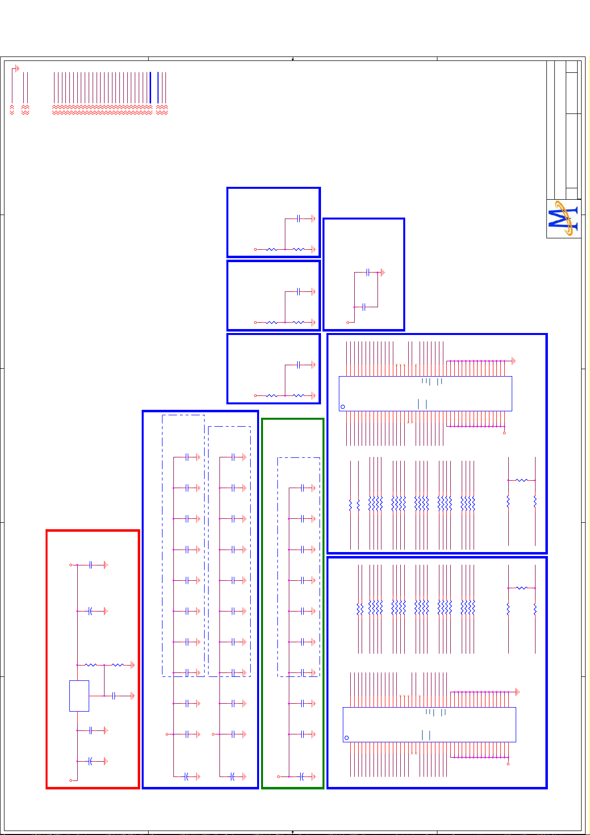
GND
AV125
GND3,4,6,7,8,9,10,11,12,13,14
AV1253,4,8,9,12
1
2
DV33
DV333,4,6,7,11,12
RCLK1
RCLK1#
RCLK1#4
RDQS3#
RCLK14
RDQS3#4
RDQS3
RDQS2#
RDQS34
RDQS2
RDQS2#4
RDQM2
RDQS24
RDQM3
RDQM24
RVREF3
RDQM34
MEM_VREF34
RCKE
RCKE4
RWE#
V1
V1
V1
Rev
Rev
Rev
of
of
of
515Friday, December 04, 2009
515Friday, December 04, 2009
RCLK0#
RODT4
RCLK0
RCLK0#4
RDQM0
AVDD12_MEMPLL
No.1-2, Innovation Rd 1, SBIP, Hsin-Chu City 300
No.1-2, Innovation Rd 1, SBIP, Hsin-Chu City 300
No.1-2, Innovation Rd 1, SBIP, Hsin-Chu City 300
MediaTek Confidential
MediaTek Confidential
RCLK04
RDQS1#4
RDQS14
DDRV4
RDQS0#4
RDQS04
RDQM14
RDQM04
RDQ[31..0]4
RA[12..0]4
AVDD12_MEMPLL3,4,8,9,12
CD41
0.1uF
CD41
0.1uF
RD23
1K_1%
RD23
1K_1%
1K_1%
1K_1%
1K_1%
CD40
CD40
RD26
RD26
1K_1%
0.1uF
0.1uF
1K_1%
1K_1%
CD31
0.1uF
CD31
0.1uF
CD4
NS/1uF
CD4
NS/1uF
AVSS12_MEMPLL
AVDD12_MEMPLL
AV12_MEMPLL
AV125
DDRVDDRVDDRV
RVREF
MT5305A
RVREF
DDR#2
RD24
RD24
RD25
RD25
MediaTek Confidential
RCAS#
RCS#
RRAS#
RBA0
RBA1
RODT
RWE#4
RBA04
RBA14
RCAS#4
RCS#4
RRAS#4
RDQ[31..0]
MRA[12..0]
VCC2IO
RDQS0
RDQM1
RDQS0#
RDQS1
RDQS1#
515Friday, December 04, 2009
Drawn
Drawn
Drawn
DDR2 x 2
DDR2 x 2
DDR2 x 2
Document Number
Document Number
Document Number
Size
Size
Size
Title
Title
Title
1
MT5305A P1V1
MT5305A P1V1
MT5305A P1V1
C
C
C
Date: Sheet
Date: Sheet
Date: Sheet
2
TEL:(03)567-0766 FAX:(03)578-7610
TEL:(03)567-0766 FAX:(03)578-7610
TEL:(03)567-0766 FAX:(03)578-7610
MediaTek Inc.
MediaTek Inc.
MediaTek Inc.
CD42
0.1uF
CD42
0.1uF
RVREF1 RVREF3RVREF2
RD18
1K_1%
RD18
1K_1%
1K_1%
Main Chip Bottom Side
DDRV
1K_1%
CM23
0.1uF
CM23
0.1uF
CM22
0.1uF
CM22
0.1uF
CM21
0.1uF
CM21
0.1uF
CM20
0.1uF
CM20
0.1uF
CM19
0.1uF
CM19
0.1uF
CM18
0.1uF
CM18
0.1uF
CM17
0.1uF
CM17
0.1uF
CM16
1uF
CM16
1uF
CM15
4.7uF/10V
CM15
4.7uF/10V
CEM1
+
47uF/16V+CEM1
47uF/16V
RD17
RD17
RVREF
DDR#1
3
CD3
NS/0.1uF
CD3
NS/0.1uF
DDRVDV33
4
5
2
OUT
IN
UD1 AP1084-ADJUD1 AP1084-ADJ
3
CED2
+
RD1
RD1
ADJ/GND
CD1
CD1
CED1
+
10uF/16v+CED2
10uF/16v
280_1%
R0603/SMD
280_1%
R0603/SMD
1
0.1uF
0.1uF
10uF/16v+CED1
10uF/16v
1.25 x (1+121/280)+55uA*121 = 1.8V for DDR2
CD32 for improve High Frequecy line rejection
RD2
121_1%
R0603/SMD
RD2
121_1%
R0603/SMD
CD32
CD32
4.7uF/10V
4.7uF/10V
DRAM POWER DDRV
CD20
NS/0.1uF
CD20
NS/0.1uF
CD19
0.1uF
CD19
0.1uF
DDR#1 Bottom Side
CD18
0.1uF
CD18
0.1uF
CD17
0.1uF
CD17
0.1uF
CD16
0.1uF
CD16
0.1uF
CD15
0.1uF
CD15
0.1uF
CD14
0.1uF
CD14
0.1uF
CD13
0.1uF
CD13
0.1uF
CD12
1uF
CD12
1uF
CD11
4.7uF/10V
CD11
4.7uF/10V
DDRV
[ RESERVE ]
CED4
CED4
NS/47uF/16V
NS/47uF/16V
+
+
DRAM DE-CAP.
CD30
NS/0.1uF
CD30
NS/0.1uF
CD29
0.1uF
CD29
0.1uF
DDR#2 Bottom Side
CD28
0.1uF
CD28
0.1uF
CD27
0.1uF
CD27
0.1uF
CD26
0.1uF
CD26
0.1uF
CD25
0.1uF
CD25
0.1uF
CD24
0.1uF
CD24
0.1uF
CD23
0.1uF
CD23
0.1uF
CD22
1uF
CD22
1uF
CD21
4.7uF/10V
CD21
4.7uF/10V
DDRV
[ RESERVE ]
CED5
CED5
NS/47uF/16V
NS/47uF/16V
+
+
MT5305A DE-CAP.
1_A0
1_A1
1_A2
1_A3
1_A4
1_A5
1_A6
1_A7
1_A8
M8
A1M3A2M7A0
A3N2A5N3A6N7A4N8A7P2A9
DQ6
DQ7
DQ1
DQ0
DQ4
DQ3H3DQ2
DQ5
UD2
UD2
Damping for DDR#1 ADDR/CMD
Damping for DDR#2 ADDR/CMD
F1
H1
H7
H9
G2
G8
RDQ1
RDQ2
RDQ3
RDQ6
RDQ5
RDQ0
RDQ4
RA11
RA8
GNDGNDGNDGND
1 2
RND9 56RND9 56
NEAR BRANCH
RD19 56RD19 56
RD22 56RD22 56
1_A8
1_A11
RA8
RA11
1 2
RND10 56RND10 56
NEAR BRANCH
RD21 56RD21 56
RD20 56RD20 56
2_A11
2_A8
2_A0
2_A1
2_A2
2_A3
2_A4
2_A5
M8
A1M3A2M7A0
A3N2A5N3A6N7A4N8A7P2A9
DQ1
DQ0
DQ4
DQ3H3DQ2
UD3
UD3
H1
H7
H9
G2
G8
RDQ16
RDQ17
RDQ19
RDQ18
RDQ21
RDQ20
F9
RDQ7
1_A9
3 4
RA9
RA9
3 4
2_A9
2_A6
DQ5
F1
RDQ22
RDQ8
1_A12
RA12
RA12
2_A12
2_A7
DQ6
RDQ23
P8
C8
5 6
5 6
F9
1_A9
P3
A8
DQ8
C2
RDQ9
1_A7
7 8
RA7
RA7
7 8
2_A7
2_A8
P8
DQ7
C8
RDQ24
1_A10
M2
DQ9
D7
RDQ10
2_A9
P3
A8
DQ8
C2
RDQ25
1_A11
P7
A10/AP
RDQ11
RND1 56RND1 56
RND2 56RND2 56
2_A10
M2
DQ9
D7
RDQ26
1_A12
R2
A11
A12
DQ12
DQ11D3DQ10
D1
RDQ12
RCAS#
1 2
1_CAS#
RODT
1 2
2_ODT
2_A11
P7
A11
A10/AP
DQ11D3DQ10
RDQ27
R3
R8
NC/A13
DQ13
B1
D9
RDQ14
RDQ13
RRAS#
RCS#
3 4
5 6
1_CS#
1_RAS#
RCS#
RRAS#
3 4
5 6
2_RAS#
2_CS#
2_A12
R2
R8
A12
DQ12
D1
D9
RDQ28
RDQ29
R7
NC/A14
NC/N15
DQ14
DQ15
B9
RDQ15
RODT
7 8
1_ODT
RCAS#
7 8
2_CAS#
R3
NC/A14
NC/A13
DQ14
DQ13
B1
RDQ30
1_BA0
A2
R7
B9
RDQ31
1_BA1
L3
BA0L2BA1
NC
NC
E2
RND3 56RND3 56
RND4 56RND4 56
2_BA0
BA0L2BA1
NC/N15
NC
DQ15
A2
CLK0
L1
NC/BA2
UDQS
B7
RDQS1
RDQS1#
RA4
RA6
123456
1_A6
1_A4
RA2
RA0
1 2
2_A0
2_A2
2_BA1
L3
NC
E2
RDQS3
J8
CK
UDQS
A8
3 4
L1
NC/BA2
UDQS
B7
CLK0#
1_CS#
K8
CK
F7
E8
RDQS0
RDQS0#
RA2
RA0
78
1_A2
1_A0
RA4
RA6
5 6
7 8
2_A4
2_A6
CLK1#
CLK1
J8
CK
UDQS
F7
A8
RDQS3#
RDQS2
1_CAS#
L7CSL8
CAS
UDM
LDQS
B3
RDQM1
2_CS#
LDQS
E8
RDQS2#
1_RAS#
1_ODT
K9
K7
ODT
LDMF3LDQS
J2
RDQM0
RVREF1
RBA1
123456
RND5 56RND5 56
1_BA1
RBA1
1 2
RND6 56RND6 56
2_BA1
2_ODT
2_CAS#
K9
L7CSL8
CAS
UDM
B3
RDQM2
RDQM3
1_WE#
K3
WE
RAS
VREF
CKE
K2
1_CKE
RBA0
1_BA0
RBA0
3 4
2_BA0
K7CKK8
RAS
ODT
LDMF3LDQS
VREF
J2
RVREF2 2_RAS#
A3
VSS
VDD
A1
RWE#
1_WE#
RWE#
5 6
2_WE#
2_WE#
K3
WE
CKE
K2
2_CKE
A7
VSSQ
VDDQ
A9
RCKE
78
1_CKE
RCKE
7 8
2_CKE
A3
VSS
VDD
A1
B2
B8
D2
D8
E7
F2
F8
H2
H8
E3
J3
N1
P9
J7
VSS
VSS
VSS
G1
VSSQ
VDDQ
G3
VSSQ
VDDQ
G7
VSSQ
VDDQ
G9
VSSQ
VDDQ
VDDL
J1
J9
VSSDL
VDD
M9
VSS
VDD
VDD
R1
DDRV
CLK0
DDR#1
NT5TU32M16CG-25C
NT5TU32M16CG-25C
CLK0#RCLK0#
RD7
100
RD7
100
3
VSSQ
VSSQ
VSSQ
VSSQ
VSSQ
VDDQ
VDDQC3VDDQ
VDDQ
VDD
VDDQ
E1
E9
C1
C7
C9
RA3
RA1
RA5
RA10
NEAR DRAMNEAR IC
123456
78
RND7 56RND7 56
1_A5
1_A1
1_A10
1_A3
RA3
RA1
RA5
RA10
1 2
3 4
5 6
7 8
RND8 56RND8 56
2_A1
2_A5
2_A10
2_A3
E3
A7
B2
B8
D2
D8
E7
VSS
VSSQ
VSSQ
VSSQ
VSSQ
VSSQ
VDDQ
VDDQ
VDDQC3VDDQ
VDDQ
VDD
A9
E1
E9
C1
C7
C9
RD6 22RD6 22
RD8 22RD8 22
RCLK0
Damping and Termination for CLK
CLK1
CLK1#RCLK1#
RD13
100
RD13
100
NEAR DRAMNEAR IC
RD14 22RD14 22
RD12 22RD12 22
RCLK1
Damping and Termination for CLK
J3
N1
P9
F2
F8
H2
H8
J7
VSS
VSS
VSSQ
VDDQ
VSS
VSSQ
VSSQ
VSSQ
VSSQ
VSSDL
VDDQ
VDDQ
VDDQ
VDDL
VDD
VDD
VDD
VDDQ
G1
G7
G9
G3
J1
J9
R1
M9
DDRV
DDR#2
NT5TU32M16CG-25C
NT5TU32M16CG-25C
4
5
D D
C C
B B
A A
Page 35

Rev
Rev
Rev
of
of
of
55Friday, December 04, 2009
55Friday, December 04, 2009
55Friday, December 04, 2009
Max
Drawn
Drawn
ATP30
ECKN
AECKP
AECKN
ECKP
AE3N
ATP30
ATP29
ATP29
TP/SMD/D0.6
TP/SMD/D0.6
TP/SMD/D0.6
TP/SMD/D0.6
E3N
AE3P
E3P
AE4P
AE4N
PanelVCC
LVDSVDD
PanelVCC
AC160
AC160
0.1uF
0.1uF
C0402/SMD/A
C0402/SMD/A
ATP27
ATP27
ATP28
ATP28
TP/SMD/D0.6
TP/SMD/D0.6
TP/SMD/D0.6
TP/SMD/D0.6
O1N
O1P
O0N
O0P
O2N
O2P
OCKN
OCKP
O3N
AO2N
AO2P
AOCKP
AOCKN
AO3N
O3P
AO3P
1
AO1P
AO1N
AO0P
AM81_AV33 2,3
AM81_AV33
AM81_AV33
AM81_AV12 2,3,4
AM81_AV12
AM81_AV12
GND 2,3,4
DIMMING_OUT
BL_PWM
GND
DIMMING_OUT
BL_PWM
AO0N
LVDS RX Connector
E0N
E0P
AO4P
AO4N
AE0N
AE0P
AE1N
LVDS Input
E1N
AE1P
E1P
E2N
E2P
AE2P
AE2N
Drawn
LVDS TX / RX
LVDS TX / RX
LVDS TX / RX
MT8281_D2V1
MT8281_D2V1
MT8281_D2V1
Document Number
Document Number
Document Number
C
C
C
Size
Size
Size
Title
Title
Title
Date: Sheet
Date: Sheet
Date: Sheet
1
TEL:(03)567-0766 FAX:(03)578-7610
No.1-2, Innovation Rd 1, SBIP, Hsin-Chu City 300
TEL:(03)567-0766 FAX:(03)578-7610
No.1-2, Innovation Rd 1, SBIP, Hsin-Chu City 300
TEL:(03)567-0766 FAX:(03)578-7610
No.1-2, Innovation Rd 1, SBIP, Hsin-Chu City 300
MediaTek Confidential
MediaTek Confidential
MediaTek Confidential
MediaTek Inc.
MediaTek Inc.
MediaTek Inc.
2
TX_BE0P
TX_BE1P
TX_BOCKP
TX_BO3P
11 12
13 14
15 16
TX_BOCKN
TX_BO3N
TX_BO4P
2019
17 18
TX_BO4N
22
21
23 24
TX_BE0N
TX_BE1N
TX_BE2P
TX_BECKP
25 26
27 28
29 30
TX_BE2N
TX_BECKN
TX_BE3P
TX_BE4P
31 32
33 34
TX_BE3N
TX_BE4N
A2006WV0-17X2
HDR2X17\2MM\SA
A2006WV0-17X2
HDR2X17\2MM\SA
AC1017
0.1uF
AC1017
0.1uF
M81_LVDSVDD
AC1016
0.1uF
AC1016
0.1uF
ACE650
220uF/16V/NS
ACE650
220uF/16V/NS
+
+
C0402/SMD/A
C0402/SMD/A
C0402/SMD/A
C0402/SMD/A
CAP-3.5-D8H9
CAP-3.5-D8H9
CND5
CND5
LVDS PORT BLVDS PORT A
TX_BO0P
TX_BO1P
TX_BO2P
M81_LVDSVDD
1 2
3 4
5 6
7 8
9 10
TX_BO0N
TX_BO1N
TX_BO2N
M81_LVDSVDD
2
For 1080P 120Hz
3
4.7K/NC
4.7K/NC
4.7K
4.7K
4.7K/NC
4.7K/NC
PanelVCC
R0402/SMD
R0402/SMD
R0402/SMD
R0402/SMD
R0402/SMD
R0402/SMD
BR38
BR38
BR37
BR37
BR36
BR36
4.7K/NC
4.7K/NC
4.7K/NC
4.7K/NC
0
0
R0402/SMD
R0402/SMD
R0402/SMD
R0402/SMD
R0402/SMD
R0402/SMD
AC1012
330pF
AC1012
330pF
C0402/SMD/A
C0402/SMD/A
AC1011
0.1uF
AC1011
0.1uF
C0402/SMD/A
C0402/SMD/A
AC1010
4.7uF/10V
AC1010
4.7uF/10V
AV33_LVDSRX
AV33_LVDSRX
AM81_AV33
4
AFB80
AFB80
0603_Bead
0603_Bead
BEAD/SMD/0603
BEAD/SMD/0603
C0805/SMD
C0805/SMD
AV12_LVDSRX
AV12_LVDSRX
AFB81
AFB81
0603_Bead
0603_Bead
AM81_AV12
AC1015
330pF
AC1015
330pF
C0402/SMD/A
C0402/SMD/A
AC1014
0.1uF
AC1014
0.1uF
C0402/SMD/A
C0402/SMD/A
AC1013
4.7uF/10V
AC1013
4.7uF/10V
C0805/SMD
C0805/SMD
BEAD/SMD/0603
BEAD/SMD/0603
CND3
CND3
TX_AO0P
1 2
3 4
TX_AO0N
TX_AO1P
5 6
7 8
TX_AO1N
TX_AOCKP
TX_AO2P
9 10
11 12
13 14
TX_AO2N
TX_AOCKN
OPC SELECT=1
TX_AO3P
PNL1
2019
15 16
17 18
TX_AO3N
22
21
23 24
TX_AO4N TX_AO4P
DIMMING_OUT#BL_PWM#
M81_LVDSVDD
M81_LVDSVDD
25 26
27 28
29 30
31 32
M81_LVDSVDD
M81_LVDSVDD
A2006WV0-16X2
HDR2X16\2MM\SA
A2006WV0-16X2
HDR2X16\2MM\SA
BR39 0
BR39 0
BL_PWM# BL_PWM
R0402/SMD
R0402/SMD
BR46 0R/NC
BR46 0R/NC
DIMMING_OUT# DIMMING_OUT
246
R0402/SMD
R0402/SMD
135791113
CND4
CND4
TX_AE0N TX_AE0P
TX_AE1N TX_AE1P
TX_AECKP
8
TX_AE2N TX_AE2P
TX_AE4P
101214
TX_AE4N
TX_AE3N TX_AE3P
TX_AECKN
PNL2
16
15
8X2 2mm
HDR2X8\2MM\SA
8X2 2mm
HDR2X8\2MM\SA
AM81_AV33
BR35
BR35
BR34
BR34
BR33
BR33
3
4
5
LVDS RX
AOCKP
AOCKN
AO3P
AO1P
AO1N
AO2P
AO2N
AO0P
AO0N
W7
Y7
W6
Y6
RO0PW4RO1PW5RO2P
AU60D
AU60D
AVDD33_LVDSRXOU6AVDD12_LVDSRX_CK
AV33_LVDSRX
RO0NY4RO1NY5RO2N
ROCLKP
ROCLKN
AVDD33_LVDSRXE
AVDD12_LVDSRXU8TN_VIPLL
U7
U10
AV12_LVDSRX
RO3PW8RO4P
AO3N
AO4N
AE0P
AO4P
W10
W9
Y9
RE0P
RO3NY8RO4N
AVSS33_LVDSRX
AVSS33_LVDSRX
AVSS12_LVDSRX_CK
AVSS12_LVDSRXV8TP_VIPLL
V6
V7
V10
D D
AE1P
AE1N
AE0NVIPLL_TN
W11
Y10
Y11
RE1P
RE0N
V9
U9
VIPLL_TP
ATP12
ATP12
ATP13
ATP13
AE2P
AE2N
AECKP
W13
W12
Y12
RE2P
RE1N
RE2N
RECLKP
TP/SMD/D0.6
TP/SMD/D0.6
TP/SMD/D0.6
TP/SMD/D0.6
AE3P
AECKN
Y13
W14
RECLKN
RE3P
AE3N
Y14
AE4P
W15
RE3N
AE4N
Y15
RE4P
RE4N
MT8282_BGA_20081008_Final
MT8282_BGA_20081008_Final
MT8282/BGA309/P1.0/B0.5
MT8282/BGA309/P1.0/B0.5
TX_AO2P
TX_AO2N
TX_AO1P
TX_AO1N
TX_AO0P
TX_AO0N
TX_AOCKP
G17
D17
E17
F17
D18
E18
F18
AU60E
AU60E
AO0P
AO1P
AO2P
AO0N
AO1N
AO2N
AOCKP
AVDD33_LVDSA
AVDD33_LVDSA
AVDD12_VPLL
AVDD12_LVDS
AVDD33_LVDSB
AVDD33_LVDSB
L19
K17
K18
K19
V17
U16
AV12_LVDSTX
AV33_LVDSTX
AV12_LVDSVPLL
LVDS TX
TX_AO3P
TX_AO3N
TX_AOCKN
G18
H17
H18
AO3P
AO3N
AOCKN
AVSS33_LVDSA
H16
C C
TX_AE0N
TX_AO4P
TX_AO4N
TX_AE0P
D20
D19
J17
J18
AE0P
AO4P
AO4N
AVSS33_LVDSA
AVSS33_LVDSB
AVSS33_LVDSB
AVSS33_LVDSB
J16
T16
V16
V19
R16
PNL0
LVDS FORMAT
=0
TX_AECKP
TX_AE2P
TX_AE2N
TX_AE1P
TX_AE1N
E20
F20
E19
F19
G20
AE1P
AE2P
AE0N
AE1N
AE2N
AECKP
AVSS12_VPLL
AVSS12_LVDS
AVSS33_LVDSB
L17
L18
TX_AE3P
TX_AE3N
TX_AECKN
H20
H19
G19
AE3P
AE3N
AECKN
TP_VPLL
K20
VPLL_TP
TP/SMD/D0.6
TP/SMD/D0.6
ATP14
ATP14
TX_AE4P
TX_AE4N
J20
J19
AE4P
AE4N
TX_BO1P
TX_BO0P
TX_BO0N
M19
M20
BO0P
BO0N
TX_BO1N
N19
N20
BO1P
TX_BO2P
TX_BO2N
P19
P20
BO2P
BO1N
TX_BOCKP
TX_BOCKN
R19
R20
BO2N
BOCKP
BOCKN
TX_BO3P
TX_BO3N
T19
T20
BO3P
BO3N
TX_BO4P
TX_BO4N
U19
U20
BO4P
BO4N
TX_BE0P
TX_BE0N
M18
M17
BE0P
BE0N
TX_BE2P
TX_BE1N
TX_BE1P
N18
N17
BE1P
BE1N
TX_BE2N
P18
P17
BE2P
TX_BECKP
TX_BECKN
R17
R18
BE2N
BECKP
B B
TX_BE3N
TX_BE3P
T18
T17
BE3P
BECKN
TX_BE4P
U18
BE4P
BE3N
TX_BE4N
U17
BE4N
AC1022
AC1022
AC1021
AC1021
AV33_LVDSTX
AC1020
AC1020
AV33_LVDSTX
MT8282_BGA_20081008_Final
MT8282_BGA_20081008_Final
MT8282/BGA309/P1.0/B0.5
MT8282/BGA309/P1.0/B0.5
BEAD/SMD/0603
BEAD/SMD/0603
AFB82
AFB82
0603_Bead
0603_Bead
AM81_AV33
PNL0
PNL1
PNL2
0.1UF
0.1UF
20081104 modify by ACD YB Luo
C0402/SMD/A
C0402/SMD/A
AC1024
0.1uF
AC1024
AV12_LVDSTX
AV12_LVDSTX
AFB83
AFB83
0603_Bead
0603_Bead
AM81_AV12
0.1uF
AC1023
4.7uF/10V
AC1023
4.7uF/10V
BEAD/SMD/0603
BEAD/SMD/0603
0.1uF
0.1uF
4.7uF/10V
4.7uF/10V
C0402/SMD/A
C0402/SMD/A
C0805/SMD
C0805/SMD
C0402/SMD/A
C0402/SMD/A
AV12_LVDSVPLL
C0805/SMD
C0805/SMD
AFB84
AFB84
AM81_AV12
AC1026
0.1uF
AC1026
0.1uF
AC1025
4.7uF/10V
AC1025
4.7uF/10V
AV12_LVDSVPLL
BEAD/SMD/0603
BEAD/SMD/0603
0603_Bead
0603_Bead
A A
C0402/SMD/A
C0402/SMD/A
C0805/SMD
C0805/SMD
5
Page 36
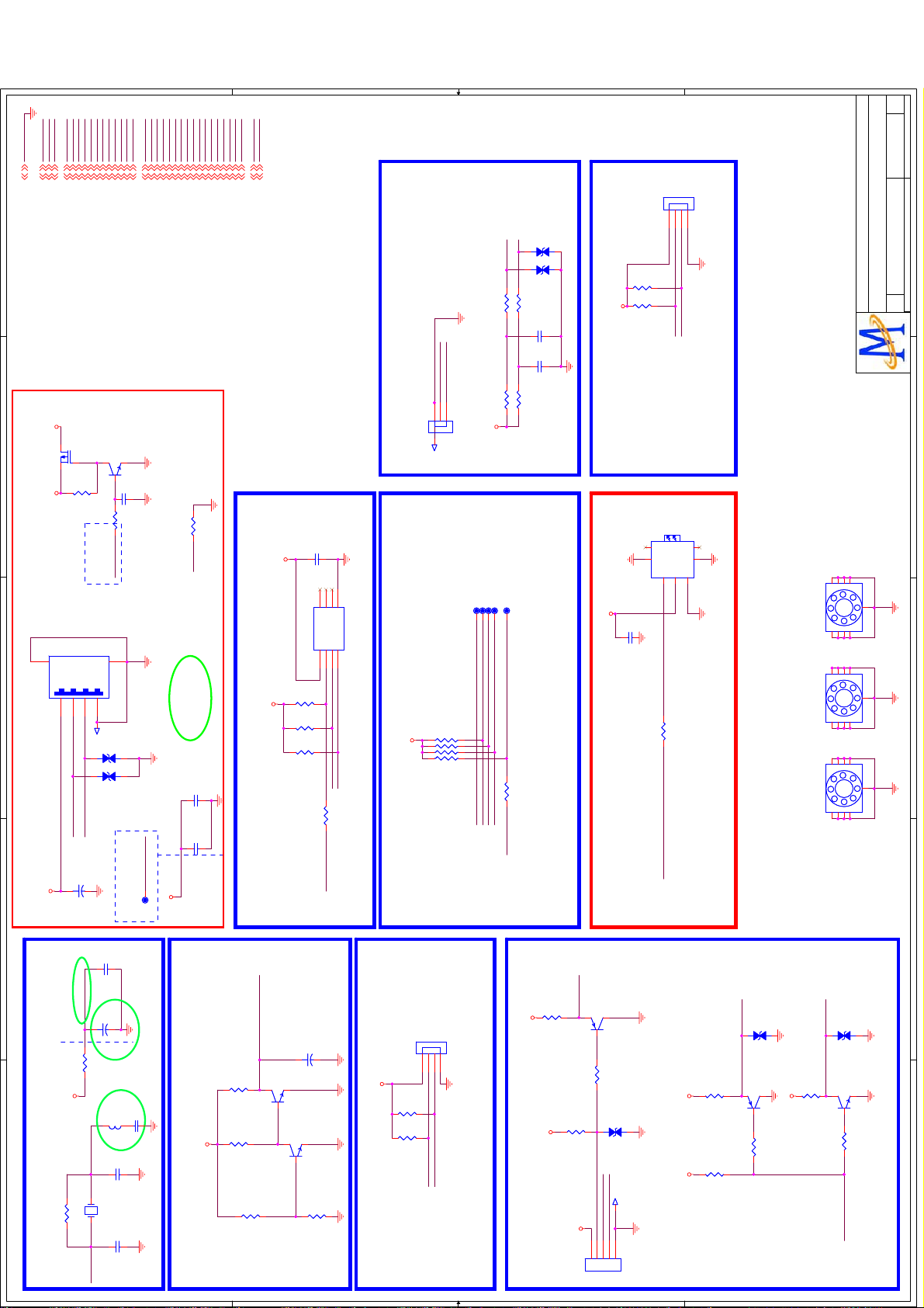
V1
V1
V1
Rev
Rev
Rev
of
of
GND
+5VSB
AV33
+3V3SB
AV125
DV33
U0TX
U0RX
ASPDIF
+5V
USB_PWR_EN0
USB_VRT
USB_PWR_ERR0
USB_DP0
USB_DM0
U1RX
ORESET#
OXTALO
OSDA0
OSCL0
AVDD33_XTAL_STB
OIRI
OXTALI
JTDO
JTCK
JTRST#
OPCTRL2
AVDD33_USB
OPWM2
ADIN1
ADIN0
DVD_IR
OPCTRL0
U1TX
U1RX
of
615Friday, December 04, 2009
615Friday, December 04, 2009
615Friday, December 04, 2009
By Ray
Drawn
Drawn
Drawn
GND3,4,5,7,8,9,10,11,12,13,14
1
+5VSB3,9,14
+3V3SB3,8,9,12
2
AO3401
AO3401
6
3
CNA2
CNA2
USB PORT
+5V_USB
4
DV333,4,5,7,11,12
AV333,4,8,9,10,12,13
AV1253,4,5,8,9,12
+5V3,8,10,12,14
23
Q62
Q62
1
R1768
47K
R1768
47K
+5V +5V_USB
GND
__VBUS1__D-2__D+3__GND
USB_DM0
USB_DP0
CE15
100uF/16V
CE15
100uF/16V
+
+
U1RX4
USB_PWR_EN04
USB_PWR_ERR04
U0RX4,9
U0TX4,9
ASPDIF4,7
Q63
2N3904
Q63
2N3904
1
C744
C744
R1769
R1769
USB_PWR_EN0
LO = > POWER OFF
HI = > POWER ON
GND
5
USB CON
USB CON
4
T14T14
D36
D36
12
12
D37
D37
ESD_0402_0.15pF
ESD_0402_0.15pF
XC2
0.1uF
XC2
0.1uF
USB_DM04
USB_DP04
USB_VRT4
ORESET#4
OXTALO4
3 2
1uF
1uF
47K
47K
ESD_0402_0.15pF
ESD_0402_0.15pF
USB_PWR_ERR0
LO=> OC
HI = > NORMAL
TP25TP25
OSDA04
OSCL04
AVDD33_XTAL_STB4
OXTALI4
NEAR IC
AVDD33_USB
NEAR IC
AV33
OIRI4
JTDO4
OPWM24
USB_VRT
UC2
UC2
UC3
UC3
JTCK4
UR5
UR5
0.1uF
0.1uF
NS/1uF
NS/1uF
JTRST#4
OPCTRL24
AVDD33_USB3,4,8,9,10,12,13
ADIN14
ADIN04
DVD_IR9
OPCTRL04
U1RX4
U1TX4
5.1K_1%
5.1K_1%
DV33
Modify 09.06.19
AVSS33_USB
SYSTEM EEPROM
DV33
CNB2
CNB2
PH3-4A/NC
PH3-4A/NC
123
4
ESD_0402_10pF
ESD_0402_10pF
ESD_0402_10pF
ESD_0402_10pF
D5
D5
K0ADIN0
K1
12
D4
D4
12
R1773 1.5KR1773 1.5K
R1771 1.5KR1771 1.5K
C628
0.1uF
C628
0.1uF
ADIN1
C629
+3V3SB
TP51TP51
JTCK
R1770 15KR1770 15K
JTDO
C629
0.1uF
0.1uF
R1772 15KR1772 15K
JR333JR3
33
K1
K0
321
CNE2
TJC2004-3AW
CNE2
KEY PANEL
YC1
0.1uF
YC1
0.1uF
4
3
YU1
YU1
NC1NC2NC
GND
SDA5SCL6WP7VCC
EEPROM 24C32-W
EEPROM 24C32-W
8
YR3
4.7K
YR3
4.7K
IIC ADDRESS "A0"
YR2
4.7K
YR2
4.7K
YR1
4.7K
YR1
4.7K
OSCL0
OSDA0
YR5 100YR5 100
OPCTRL0
Hi = > WP
Lo = > WRITE
DV33
TJC2004-3AW
T8T8
TP47TP47
TP50TP50
TP46TP46
TP48TP48
JRN1
10K
JRN1
10K
7 8
5 6
3 4
1 2
OPCTRL2
OPWM2
JTRST#
JTAG Port
AR7
4.7K
AR7
4.7K
AR8
4.7K
AR8
4.7K
+3V3SB
U1RX
U1TX
Layout anywhere
FOR DEBUGGING
RESEVED FOR EXTEND FUNCTION
J3
SPDIF_VJ3SPDIF_V
7
6
4
1
SPDIF
PR133PR1
ASPDIF
7
5
5
GND3VCC2IN
HOLE/GNDH4HOLE/GND
HOLE/GNDH3HOLE/GND
33
HOLE/GNDH1HOLE/GND
+5V
C812
0.1uF
C812
0.1uF
Near Connector
6
4
OPTICAL
TEL:(03)567-0766 FAX:(03)578-7610
No.1-2, Innovation Rd 1, SBIP, Hsin-Chu City 300
TEL:(03)567-0766 FAX:(03)578-7610
No.1-2, Innovation Rd 1, SBIP, Hsin-Chu City 300
TEL:(03)567-0766 FAX:(03)578-7610
No.1-2, Innovation Rd 1, SBIP, Hsin-Chu City 300
MediaTek Confidential
MediaTek Confidential
MediaTek Confidential
MediaTek Inc.
MediaTek Inc.
MediaTek Inc.
5
2233445
1
H4
9988776
6
5
2233445
1
H3
9988776
6
5
2233445
1
H1
9988776
6
PERIPHERAL
PERIPHERAL
PERIPHERAL
Document Number
Document Number
Document Number
Size
Size
Size
Title
Title
Title
1
1
1
1
MT5305A P1V1
MT5305A P1V1
MT5305A P1V1
C
C
C
Date: Sheet
Date: Sheet
Date: Sheet
2
3
4
NEAR IC
R1767 0R1767 0
+3V3SB
5
XY1
XY1
XR9 1MXR9 1M
54MHz CRYSTAL
AVDD33_XTAL_STB
AVSS33_XTAL
XC18
10uF/16v+XC18
10uF/16v
+
XL3
820nH
XL3
820nH
OXTALO
XC4
XC4
54MHz
54MHz
XC3
XC3
OXTALI
D D
10pF
10pF
10pF
10pF
20090612
XC17
1nF
XC17
1nF
+3V3SB
RESET#
ORESET#
CNB1
+3V3SB
CNB1
123
4
AR6
4.7K
AR6
4.7K
AR5
4.7K
AR5
4.7K
U0TX
U0RX
FOR CODE DOWNLOAD AND DEBUGGING
PH3-4A
PH3-4A
CE643
100uF/16v
CE643
100uF/16v
+
+
TR2
4.7K
TR2
4.7K
Q64
2N3904
Q64
2N3904
3 2
1
TR1
10K
TR1
10K
Q65
2N3904
Q65
2N3904
3 2
1
TR6
3.9K
TR6
TR3
12K
TR3
12K
3.9K
+3V3SB
UART Port 0
C C
DVD_IR
R15
4.7K
R15
4.7K
Q2
32
1
2N3906Q22N3906
R1774 100R1774 100
OIRIIR_IN
ESD_0402_10pF
ESD_0402_10pF
D2
D2
R13
4.7K
R13
4.7K
+5VSB
CNE1
CNE1
B B
12
LED_GRE#
LED_RED#
12345
T7T7
TJC2004-5AW
TJC2004-5AW
+3V3SB
IR Receiver & LED
+3V3SB
+3V3SB
R661kR66
R1775
R1775
1k
10k
10k
ESD_0402_10pF
ESD_0402_10pF
D7
D7
LED_RED#
12
Q51
Q51
32
1
R1776 4.7KR1776 4.7K
2N3906
2N3906
+3V3SB
R17771kR1777
A A
LED_GRE#
LED_GRE#
12
1k
ESD_0402_10pF
ESD_0402_10pF
D8
D8
Q67
2N3904
Q67
2N3904
3 2
1
R1778 4.7KR1778 4.7K
OPCTRL2
HI = > LED RED
LO=> LED GREEN
5
Page 37

V1
V1
V1
Rev
Rev
Rev
of
of
GND
DV33
OPWM0
ASPDIF
OPCTRL3
ORESET#
GPIO1
PDD0
POOE#
POCE0#
PDD1
OPWM1
of
715Friday, November 27, 2009
715Friday, November 27, 2009
715Friday, November 27, 2009
By Ray
Drawn
Drawn
Drawn
1
GND3,4,5,6,8,9,10,11,12,13,14
2
3
OPCTRL34
ASPDIF4,6
OPWM04
DV333,4,5,6,11,12
TEL:(03)567-0766 FAX:(03)578-7610
No.1-2, Innovation Rd 1, SBIP, Hsin-Chu City 300
TEL:(03)567-0766 FAX:(03)578-7610
No.1-2, Innovation Rd 1, SBIP, Hsin-Chu City 300
TEL:(03)567-0766 FAX:(03)578-7610
ORESET#4,6
GPIO14
POCE0#4
POOE#4
PDD04
PDD14
OPWM14
No.1-2, Innovation Rd 1, SBIP, Hsin-Chu City 300
MediaTek Confidential
MediaTek Confidential
MediaTek Confidential
MediaTek Inc.
MediaTek Inc.
MediaTek Inc.
1
FLASH/TRAP/BYPASS/FCI
FLASH/TRAP/BYPASS/FCI
FLASH/TRAP/BYPASS/FCI
MT5305A P1V1
MT5305A P1V1
MT5305A P1V1
Document Number
Document Number
Document Number
C
C
C
Date: Sheet
Date: Sheet
Date: Sheet
Size
Size
Size
Title
Title
Title
2
OPWM1(O)OPWM0(O)ASPDIF(O)
FR5
4.7K
FR5
4.7K
DV33
FU3
FU3
FRESET#
GND
FRESET#PDD0
PDD1
10
9
16
14
15
SI
PO311PO412PO513PO6
GND
SCLK
WP#/ACC
HOLD#1VCC2NC3PO24PO15PO06CS#7SO/PO7
8
DV33
DV33 POOE#
POCE0#
EON25B64
EON25B64
000
1
GPIO1
XTAL 54M
Strapping Mode
ICE mode + Serial boot
Strapping Mode
0
PDWNC Normal
Strapping Mode OPCTRL3(O)
3
DV33
PDD1
POOE#
DV33
SR10 4.7K/NCSR10 4.7K/NCSR17 4.7KSR17 4.7K
SR2 4.7KSR2 4.7K
OPWM0
SR4 4.7KSR4 4.7K
OPWM1
7
8
6
D5C
VCC
HOLD_
S_1Q2W_/VPP3VSS
EN25B64/NC
EN25B64/NC
4
FU2
4
FU2
GND
FC28
0.1uF
FC28
FRESET#
PDD0
POCE0#
Serial Flash Dual-Layout - 8MB default
0.1uF
DV33
MT5305A STRAPPING MODE
5
SR6 4.7KSR6 4.7K
ASPDIF
SR8 4.7KSR8 4.7K
OPCTRL3
DV33
GPIO1
4
5
D D
C C
B B
A A
Page 38

A
HDMI PORT 4
DV33
GND
+3V3SB
AV33
AV125
+5V
DV333,4,5,6,7,11,12
+3V3SB3,6,9,12
AV333,4,6,9,10,12,13,15
AV1253,4,5,9,12
+5V3,6,10,12,14
GND3,4,5,6,7,9,10,11,12,13,14,15
12
12
12
12
D102D102
D103D103
D96D96
D98D98
RX3_0B
RX3_CB
RX3_C
RX3_0
HPD3
RX3_5V
SDA_3
C746 0.1uFC746 0.1uF
R1782 47KR1782 47K
R1785 47KR1785 47K
18
16
19
17
+5V
GND
HP DET
DDC DATA
SHELL2
SHELL4
CN10
CN10
21
23
HDMI_SCL0
CEC
AVDD12_HDMI
HDMI_SDA0
HDMI_SDA04
HDMI_SCL04
AVDD12_HDMI4
CEC4
12
D99D99
RX3_1B
CEC#
SCL_3
RX3_CB
R1784 0R1784 0
13
15
12
14
NC
CK-
CEC
DDC CLK
HPD_SINK
OPWR0_5V
HPD_SINK4
OPWR0_5V4
12
D100D100
RX3_1
RX3_0B
RX3_C
9
11
10
CK+
CK Shield
12
D97D97
RX3_2B
8
D0-
D0 Shield
RX_CB
RX3_0
7
RX_C
RX_CB4
12
D95
D95
RX3_2
RX3_1B
6
D0+
RX_0B
RX_C4
D1-
RX_1B
RX_1
RX_2B
RX_0
RX_0B4
RX_04
RX_1B4
RX_14
ESD_0402_0.15pF
ESD_0402_0.15pF
1 2
1 2
D108 ESD_0402_10pFD108 ESD_0402_10pF
D104 ESD_0402_10pFD104 ESD_0402_10pF
RX3_5V
HPD3
RX3_2B
RX3_2
RX3_1
2
5
3
1
4
D2-
D1+
D2 Shield
D1 Shield
22
OSDA0
OSCL0
RX_2
OSDA04,6,11
RX_2B4
RX_24
1 2
D106 ESD_0402_10pFD106 ESD_0402_10pF
SDA_3
D2+
SHELL1
SHELL3
20
AVDD33_HDMI
OSCL04,6,11
AVDD33_HDMI4
1 2
1 2
D107 ESD_0402_10pF/NCD107 ESD_0402_10pF/NC
D105 ESD_0402_10pFD105 ESD_0402_10pF
SCL_3
CEC#
HDMI_con
HDMI_con
12
12
12
12
12
D115D115
D116D116
D110D110
D112D112
D113D113
RX2_0B
RX2_CB
RX2_C
RX2_1B
RX2_0
SDA_2
SCL_2
HPD2
RX2_5V
C748 0.1uFC748 0.1uF
R1788 47KR1788 47K
R1787 47KR1787 47K
18
15
16
19
17
14
NC
+5V
GND
HP DET
DDC CLK
DDC DATA
SHELL2
SHELL4
CN12
CN12
21
23
HDMI PORT 3
12
D114D114
RX2_1
CEC#
R1793 0R1793 0
13
CEC
RX2_CB
12
CK-
12
D111D111
RX2_2B
RX2_C
11
10
CK+
CK Shield
12
D109
D109
RX2_2
RX2_0B
8
9
D0-
RX2_0
7
D0 Shield
D101
D101
2 1
+3V3SB
ESD_0402_0.15pF
ESD_0402_0.15pF
1 2
1 2
D121 ESD_0402_10pFD121 ESD_0402_10pF
D117 ESD_0402_10pFD117 ESD_0402_10pF
RX2_5V
HPD2
RX2_1B
RX2_2B
RX2_1
5
3
6
4
D2-
D1-
D1+
D0+
D1 Shield
CEC#
R2002
27K/NC
R2002
27K/NC
RB520S-30/NC
RB520S-30/NC
R1798 0R1798 0
CEC
1 2
1 2
D118 ESD_0402_10pFD118 ESD_0402_10pF
D119 ESD_0402_10pFD119 ESD_0402_10pF
SDA_2
SCL_2
RX2_2
2
1
D2+
D2 Shield
SHELL1
SHELL3
20
22
1 2
D120 ESD_0402_10pF/NCD120 ESD_0402_10pF/NC
CEC#
HDMI SWITCH
HDMI_con
HDMI_con
HORIZONTAL MOUNT
HPD3
RX3_5V
RX1_5V
HPD1
V1
V1
V1
Rev
Rev
Rev
of
of
of
815Friday, November 27, 2009
815Friday, November 27, 2009
815Friday, November 27, 2009
Drawn
Drawn
Drawn
TEL:(03)567-0766 FAX:(03)578-7610
No.1-2, Innovation Rd 1, SBIP, Hsin-Chu City 300
TEL:(03)567-0766 FAX:(03)578-7610
No.1-2, Innovation Rd 1, SBIP, Hsin-Chu City 300
TEL:(03)567-0766 FAX:(03)578-7610
No.1-2, Innovation Rd 1, SBIP, Hsin-Chu City 300
MediaTek Confidential
MediaTek Confidential
MediaTek Confidential
MT5305A P1V1
MT5305A P1V1
MT5305A P1V1
HDMI
HDMI
HDMI
Document Number
Document Number
Document Number
MediaTek Inc.
MediaTek Inc.
MediaTek Inc.
Date: Sheet
Date: Sheet
Date: Sheet
Size
Size
Size
Title
Title
Title
Custom
Custom
Custom
RX2_2
RX2_2B
RX2_1
RX2_1B
RX2_0
RX2_0B
RX2_C
RX2_CB
RX3_2
RX3_2B
RX3_1
RX3_1B
RX3_0
RX3_0B
RX3_C
RX3_CB
HDMI_3V3
HDMI_3V3
HDMI_3V3
HDMI_3V3
35
VCC
IN4D3p34IN4D3n
HDMI_3V3
RX0_0B
33
RX0_0
GND
GND
32
GND
RX0_1B
30
IN4D2p31IN4D2n
RX0_1
29
27
VCC
IN4D1p28IN4D1n
HDMI_3V3
RX0_2
RX0_2B
GND
26
GND
SCL4
25
SDA4
HPD4
POW4
GND
REXT
I2C_CTL_EN
OE#/POWDN
S3/I2C_ADDR0
S2/SCL_CTL
S1/SDA_CTL
CEC_OUT
CEC_IN
VCC
TEST
PC1/I2C_ADDR1
PC0/I2C_RST
CEXT
GND
DDCBUF_EN
CEC
POW1
HPD1
SDA1
SCL1
100
GND
SCL_2 SCL_3
24
SDA_2
23
22
21
GND
20
19
I2C_CTL_EN
18
OE#/POWDN
17
16
S2/SCL_CTL
15
S1/SDA_CTL
14
CEC_OUT
13
CEC_IN
12
11
TP27TP27
10
9
8
7
GND
6
DDCBUF_EN
5
CEC#
4
3
2
SDA_0
1
SCL_0
R19 1KR19 1K
HPD2
R22 33KR22 33K
RX2_5V
R34 499_1%R34 499_1%
R35 100/NCR35 100/NC
CEC#
R25 100/NCR25 100/NC
HDMI_3V3
CB24 2.2uFCB24 2.2uF
R14 33KR14 33K
RX0_5V
R18 1KR18 1K
HPD0
A
GND
GND
GND
47
41
48
45
42
39
44
GND
GND
IN3D2p43IN3D2n
RX1_1B
RX1_1
VCC
IN3D1p40IN3D1n
HDMI_3V3
RX1_2
RX1_2B
36
38
GND
IN4D4p37IN4D4n
PS421
PS421
GND
RX0_CB
RX0_C
50
VCC
GND
IN3D4p49IN3D4n
IN3D3p46IN3D3n
SCL3
51
SDA3
52
SDA_3
HPD3
53
R28 1KR28 1K
R29 33KR29 33K
RX_2
RX_2B
RX_1
RX_1B
RX_0
RX_0B
RX_C
RX_CB
R26 33kR26 33k
R27 1KR27 1K
OSDA0
OSCL0
HDMI_3V3
HDMI_3V3
POW3
54
GND
55
GND
OUT_D4p
56
OUT_D4n
57
VCC
58
OUT_D3p
59
OUT_D3n
60
GND
61
GND
OUT_D2p
62
OUT_D2n
63
VCC
64
OUT_D1p
65
OUT_D1n
66
GND
67
GND
SCL_SINK
68
HDMI_SCL0
SDA_SINK
69
HDMI_SDA0
HPD_SINK
70
HPD_SINK
POW_SINK
71
POW_SINK
POW2
72
HPD2
73
SDA2
74
SDA_1
SCL2
75
SCL_1
GND76IN2D1n77IN2D1p78VCC79IN2D2n80IN2D2p81GND82IN2D3n83IN2D3p84VCC85IN2D4n86IN2D4p87GND88IN1D1n89IN1D1p90VCC91IN1D2n92IN1D2p93GND94IN1D3n95IN1D3p96VCC97IN1D4n98IN1D4p99GND
U3
U3
GND
HDMI_3V3
RX1_CB
RX1_0
RX1_0B
RX1_C
HDMI_3V3
OPWR0_5V
GND
12
D43D43
RX1_0B
CN11
CN11
12
D44D44
RX1_0
HPD1
C745 0.1uFC745 0.1uF
R1805 47KR1805 47K
R1807 47KR1807 47K
19
SHELL2
21
12
12
D46D46
D45D45
RX1_1
RX1_1B
RX1_5V
SDA_1
SCL_1
16
15
17
18
+5V
GND
HP DET
DDC CLK
DDC DATA
SHELL423SHELL524SHELL625SHELL7
26
12
D41D41
RX1_CB
12
D42D42
RX1_C
HDMI PORT 2
CEC#
R1804 0R1804 0
13
14
NC
12
D47D47
RX1_2B
RX1_CB
11
12
CK-
CK Shield
CE Remote
ESD_0402_0.15pF
ESD_0402_0.15pF
12
1 2
D49 ESD_0402_10pFD49 ESD_0402_10pF
D48
D48
RX1_2
HPD1
RX1_1B
RX1_0
RX1_0B
RX1_C
8
6
9
10
7
D0-
D0+
CK+
D0 Shield
1 2
1 2
D50 ESD_0402_10pFD50 ESD_0402_10pF
D51 ESD_0402_10pFD51 ESD_0402_10pF
RX1_5V
SDA_1
RX1_2B
RX1_1
2
5
3
4
D2-
D1-
D1+
D2 Shield
D1 Shield
1 2
1 2
D52 ESD_0402_10pFD52 ESD_0402_10pF
D53 ESD_0402_10pF/NCD53 ESD_0402_10pF/NC
SCL_1
CEC#
RX1_2
1
D2+
SHELL1
SHELL3
HDMI/HAIER
HDMI/HAIER
20
22
12
12
12
12
12
D88D88
D89D89
D65D65
D67D67
D86D86
RX0_0B
RX0_CB
RX0_C
RX0_1B
RX0_0
HPD0
RX0_5V
SDA_0
SCL_0
C747 0.1uFC747 0.1uF
R1797 47KR1797 47K
R1801 47KR1801 47K
18
15
17
16
19
+5V
GND
HP DET
DDC CLK
DDC DATA
SHELL2
SHELL423SHELL524SHELL625SHELL7
CN5
CN5
21
26
HDMI PORT 1
12
D87D87
RX0_1
14
NC
CEC#
R1795 0R1795 0
13
12
D66D66
RX0_2B
RX0_CB
11
12
CK-
CK Shield
CE Remote
12
1 2
D94 ESD_0402_10pFD94 ESD_0402_10pF
D64 ESD_0402_0.15pFD64 ESD_0402_0.15pF
RX0_2
HPD0
RX0_1B
RX0_0
RX0_0B
RX0_C
6
9
7
8
10
D1-
D0-
D0+
CK+
D0 Shield
1 2
1 2
D90 ESD_0402_10pFD90 ESD_0402_10pF
D92 ESD_0402_10pFD92 ESD_0402_10pF
RX0_5V
SDA_0
RX0_2B
RX0_1
3
4
2
5
D2-
D1+
D2 Shield
D1 Shield
1 2
1 2
D91 ESD_0402_10pFD91 ESD_0402_10pF
D93 ESD_0402_10pF/NCD93 ESD_0402_10pF/NC
SCL_0
CEC#
RX0_2
1
D2+
SHELL1
SHELL3
HDMI/HAIER
HDMI/HAIER
20
22
I2C CONTROL ADDRESS:0x9C/9D
EDID SHADOW ADDRESS:0x9E/9F
Pulled up to 3.3V on CPU side.
R16 100R16 100
R17 100R17 100
S2/SCL_CTL
S1/SDA_CTL
NEARLY SW IC
VERTICAL MOUNT
A A
HDMI_3V3
FB34 FBFB34 FB
AV33
R23 4.7KR23 4.7K
R38 4.7K/NCR38 4.7K/NC
R24 4.7KR24 4.7K
OE#/POWDN
I2C_CTL_EN
DDCBUF_EN
D17
D17
12
D16D16
12
D15D15
12
D9D9
12
0.1uF
0.1uF
CB63
CB63
0.1uF
0.1uF
CB62
CB62
0.1uF
0.1uF
CB61
CB61
0.1uF
0.1uF
CB60
CB60
R30 100R30 100
R33 4.7KR33 4.7K
R31 4.7KR31 4.7K
R32 10KR32 10K
HPD_SINK
HDMI_SCL0
HDMI_SDA0
POW_SINK
AVDD12_HDMI
NEAR MAIN IC
AV125
ESD_0402_10pF
ESD_0402_10pF
ESD ARE LAYOUTED UNDER SW(Square).
AVDD33_HDMI
NEARLY MAIN IC
AV33
HC8
8200PF
HC8
8200PF
0
HR350HR35
0.1uF
0.1uF
CB58
CB58
AVSS33_HDMI
0
HR340HR34
Page 39

V1
V1
V1
Rev
Rev
Rev
of
of
of
915Friday, December 04, 2009
915Friday, December 04, 2009
GND
AIN3_R
AIN0_R
AIN0_L
AIN3_L
+3V3SB
+5VSB
AV125
AV33
U0TX
U0RX
+5V
AIN4_L
AIN5_L
AIN4_R
AIN6_R
AIN5_R
AIN6_L
CVBS0N
CVBS1P
AVDD33_CVBS
CVBS0P
SC0
SY0
AVDD33_VGA_STB
AVDD33_VDAC
FS_VDAC
AVDD12_RGB
COMBPRPGPHSYNC
VSYNC
SOY0
COM1
PR0P
Y0P
COM0
PB1P
VMID_AADC
SOG
PR1P
PB0P
SOY1
Y1P
DACOUT1
ADIN5
ADIN2
AVDD33_AADC
U0RX
U0TX
915Friday, December 04, 2009
By Ray
Drawn
Drawn
Drawn
1
+3V3SB3,6,8,12
U0RX4,6
U0TX4,6
AIN3_L4
+5VSB3,6,14
AV1253,4,5,8,12
AV333,4,6,8,10,12,13
AIN0_L
GC8
GC8
2.2uF
2.2uF
AIN0_R
GC9
2.2uF
GC9
2.2uF
AIN3_R4
2
GND3,4,5,6,7,8,10,11,12,13,14
AIN0_L4
AIN0_R4
+5V3,6,8,10,12,14
NEARLY CONNECTOR
AV2_IN
GR17 10KGR17 10K
GR18 10KGR18 10K
12
12
AV2L_IN
AV2R_IN
7
V
V
AV2 & LR SIDE INPUT(Horizotal)
BP8
BP8
3
9
8
R
L
R
L
5
6
1
2
4
3
AIN4_L4
AIN4_R4
AIN5_L4
OC18
560pF
OC18
560pF
47K
47K
VR17
VR17
OC17
560pF
OC17
560pF
47K
47K
VR16
VR16
D70
D70
D71
D71
ESD_0402_10pF
ESD_0402_10pF
CVBS1P4
AIN5_R4
AIN6_R4
AIN6_L4
ESD_0402_10pF
ESD_0402_10pF
RCA3X1
RCA3X1
CVBS0N4
AVDD33_CVBS3,4,6,8,10,12,13
SC04
SY04
CVBS0P4
CVBS0P
NEARLY ICNEARLY AV/SV CON.
GR6 0GR6 0
AV2_IN
BP4
AVDD33_VGA_STB4
FS_VDAC4
AVDD33_VDAC3,4,6,8,10,12,13
AVDD12_RGB3,4,5,8,12
GC5
47nF
GC5
47nF
Share CVBS0N with AV1
GR5
100
GR5
100
GC6
47pF
GC6
47pF
GR875GR8
75
12
D63
D63
ESD_0402_10pF
ESD_0402_10pF
TEL:(03)567-0766 FAX:(03)578-7610
No.1-2, Innovation Rd 1, SBIP, Hsin-Chu City 300
TEL:(03)567-0766 FAX:(03)578-7610
No.1-2, Innovation Rd 1, SBIP, Hsin-Chu City 300
TEL:(03)567-0766 FAX:(03)578-7610
No.1-2, Innovation Rd 1, SBIP, Hsin-Chu City 300
MediaTek Confidential
MediaTek Confidential
U0RX4,6
U0TX4,6
GP4
COM4
RP4
VSYNC4
HSYNC4
Y1P4
COM14
PB1P4
SOG4
SOY14
SOY04
PR1P4
Y0P4
COM04
PB0P4
PR0P4
VMID_AADC4
AVDD33_AADC4,10
DACOUT14,10
ADIN54
ADIN24
AIN6_L
AIN6_RAV1R_IN
GC4 2.2uFGC4 2.2uF
GC7 2.2uFGC7 2.2uF
OC20
OC20
GR10
GR10
OC19
OC19
NEARLY CONNECTOR
GR16
GR16
AV1L_IN
AV1_IN
1
4
AV1 & LR INPUT(Vertical)
10K
10K
10K
10K
GR15
GR15
12
12
867523
redyw
redyw
BP5
BP5
GR9
GR9
D68D68
D69
D69
RCA3X1
RCA3X1
560pF
560pF
47K
47K
560pF
560pF
47K
47K
ESD_0402_10pF
ESD_0402_10pF
47nF
47nF
100
100
GC1
47pF
GC1
47pF
D55
ESD_0402_10pF
D55
ESD_0402_10pF
12
GR375GR3
75
CVBS0NAV_CVBSN
GR4 0GR4 0
CVBS1P
GC2
GC2
GR2
GR2
NEARLY ICNEARLY AV/SV CON.
GR1 0GR1 0
AV1_IN
VC13
0.1uF
VC13
0.1uF
4
3
NC1NC2NC
VU1
VU1
VR19
VR19
VR18
VR18
VR26
VR26
10K
10K
10K
10K
10K
10K
8
VGASCL_IN
VGAROMWP
GND
SDA5SCL6WP7VCC
EEPROM 24C02_5V
EEPROM 24C02_5V
VGASDA_IN
NEARLY VGA CONN.
VQ1
2N3904
VQ1
2N3904
3 2
1
VR25 10KVR25 10K
ADIN2
L : Write
H : WP
GC3
1uF
GC3
1uF
VGA_5V
VGA EEPROM
MediaTek Confidential
MediaTek Inc.
MediaTek Inc.
MediaTek Inc.
1
MT5305A P1V1
MT5305A P1V1
MT5305A P1V1
VGA/YPbPr1/S_Video Input
VGA/YPbPr1/S_Video Input
VGA/YPbPr1/S_Video Input
Document Number
Document Number
Document Number
C
C
C
Date: Sheet
Date: Sheet
Date: Sheet
Size
Size
Size
Title
Title
Title
2
3
GP
SOG
VC210nF VC210nF
VC11.5nF VC11.5nF
VR368 VR368
VFB180/100MHz VFB180/100MHz
4
D54
D54
12
NEARLY VGA CON. NEARLY IC
GRN
VD1
VD1
+5VSB
RED_GND
GRN_GND
5
RED
12345
678910
1617
1112131415
VGA CONNECTOR
UTX#
COM
BP
VC410nF VC410nF
VC510nF VC510nF
VR668 VR668
VR5100 VR5100
VC3
5pF
VC3
5pF
Connected to connector GND
VR275VR2
75
VFB280/100MHz VFB280/100MHz
VR40 VR40
D57
GRN_GND
BAV70L
BAV70L
12
D56
D56
URX#
VSYNC#
VGASCL_IN
D D
D57
12
BLU
ESD_0402_10pF
ESD_0402_10pF
T15T15
T16T16
T17T17
VP1
D-SUB15 FEMALE
VP1
D-SUB15 FEMALE
ESD_0402_10pF
ESD_0402_10pF
VGA_5V
3
2
GRN
BLU_GND
BLU
HSYNC#
VGASDA_IN
1
RP
VC810nF VC810nF
VR868 VR868
VC6
5pF
VC6
5pF
VR775VR7
75
VFB380/100MHz VFB380/100MHz
ESD_0402_10pF
ESD_0402_10pF
RED
BLU_GND
BC23
BC23
NEARLY CONN.
VR10 10KVR10 10K
VGAR_IN AIN5_R
35421
R
R
PC/DVI Audio Input
VC10
VC10
VR1175VR11
D58
D58
12
AIN5_L
2.2uF
2.2uF
2.2uF
2.2uF
BC24
BC24
VR9 10KVR9 10K
12
12
VGAL_IN
L
L
5pF
5pF
75
ESD_0402_10pF
ESD_0402_10pF
RED_GND
OC16
OC16
47K
47K
VR23
VR23
OC15
OC15
VR24
47K
VR24
47K
D59D59
D60
D60
6
7
VP2
PHONE_V
VP2
PHONE_V
VC11
NS/5pF
VC11
NS/5pF
VR13
1.33K/NC
VR13
1.33K/NC
VL1 FBVL1 FB
VR120 VR120
D61
ESD_0402_10pF
D61
ESD_0402_10pF
12
HSYNC# HSYNC
560pF
560pF
U0TXUTX#
560pF
560pF
QF7
QF7
2N7002
2N7002
3 2
ESD_0402_10pF
ESD_0402_10pF
UART at VGA PORT
R101 10KR101 10K
1
VL2 FBVL2 FB
VR140 VR140
12
VSYNC# VSYNC
U0RXURX#
QF6
QF6
2N7002
2N7002
3 2
12
12
D62
D62
1
D75D75
D74
D74
C C
VC12
NS/5pF
VC12
NS/5pF
VR15
1.33K/NC
VR15
1.33K/NC
ESD_0402_10pF
ESD_0402_10pF
ADIN2
H: PC TX Disable
L: PC TX Enable
R100 10KR100 10K
ESD_0402_10pF
ESD_0402_10pF
BC15
BC15
BR2056BR20
18
FB 80/100MHz
FB 80/100MHz
12
D79
D79
COM0
BC16 10nFBC16 10nF
BR22 100BR22 100
15pF
15pF
56
Connected to connector GND
0
BR210BR21
ESD_0402_10pF
ESD_0402_10pF
SOY0SOY0
BC131.5nF BC131.5nF
BC14 10nFBC14 10nF
BR19 68BR19 68
BR1818BR18
BL4
BL4
NEARLY VGA CON. NEARLY IC
NEARLY CONN.
PR_IN#1
Y_IN#1
PB_IN#1 Y_IN#1 Y0P
BP3
RCA3X1
BP3
867523
red gb
red gb
YPBPR/RL#1 INPUT
RCA3X1
1
4
PB0P
BC17 10nFBC17 10nF
BR24 68BR24 68
BR23 18BR23 18
BL5
BL5
12
PB_IN#1
AIN3_R
AIN3_L
2.2uF
2.2uF
2.2uF
2.2uF
BC22
BC22
BC21
BC21
BR31 10KBR31 10K
BR32 10KBR32 10K
12
12
YPBPR_R_IN#1
YPBPR_L_IN#1
4
2
red w
red w
1
3 5
B B
BC18
BC18
BR2556BR25
FB 80/100MHz
FB 80/100MHz
D80
D80
OC14
560pF
OC14
560pF
47K
47K
VR21
VR21
OC11
560pF
OC11
560pF
VR22
47K
VR22
47K
D77
D77
D76D76
BP4
RCA2X1
BP4
RCA2X1
ESD_0402_10pF
ESD_0402_10pF
15pF
15pF
56
ESD_0402_10pF
ESD_0402_10pF
12
D81
D81
PR0P
BC2010nF BC2010nF
BR28 68BR28 68
BC19
15pF
BC19
15pF
BR2656BR26
56
BR27 18BR27 18
BL6
BL6
ESD_0402_10pF
ESD_0402_10pF
FB 80/100MHz
FB 80/100MHz
PR_IN#1
NEAR IC
AVDD12_RGBAVDD33_VDAC
AV125AV33
VIDEO DAC
Near IC
OC5
0.1uF
OC5
0.1uF
OC7
NS/1uF
OC7
NS/1uF
OC3
0.1uF
OC3
0.1uF
NEAR IC NEAR IC
AVSS12_RGB
AVSS33_VDAC
OC12
OC12
OC13
OC13
AVDD33_VGA_STB
VR200 VR200
+3V3SB
OC9
OC9
AVDD33_CVBSVMID_AADC
OC10
OC10
AV33
OR1
560
OR1
560
FS_VDAC
OC8
0.1uF
OC8
0.1uF
CE1
CE1
+
+
NEAR IC
0.1uF
0.1uF
0.1uF
0.1uF
Modify 09.06.19
0.1uF
0.1uF
AVSS33_CVBS
1uF
1uF
NS/4.7uF/16v
NS/4.7uF/16v
OC6
0.1uF
OC6
0.1uF
A A
4
5
Page 40

V1
V1
V1
Rev
Rev
Rev
of
of
of
GND
+12V
AV33
+5V
+5VSB
MUTE
ADIN5
REFP_AADC
AVDD33_AADC
AVDD33_DAC
AOSDATA0
AOBCK
AOLRCK
AOMCLK
AR1
DACOUT1
AL1
AR0
AL0
10 15Friday, December 04, 2009
10 15Friday, December 04, 2009
10 15Friday, December 04, 2009
Drawn
Drawn
Drawn
GND3,4,5,6,7,8,9,11,12,13,14
WFB4FBWFB4
AV33AV33
Near IC
WFB5FBWFB5
A
VREF_25
R1799 10KR1799 10K
L147FBL147
FB
+5V HP_PWR
+12V3,11,12,13,14
AV333,4,6,8,9,12,13
+5VSB3,6,9,14
+5V3,6,8,12,14
CB3
0.1uF
CB3
0.1uF
C11
10uF/16v+C11
10uF/16v
AVDD33_DAC
+
Near IC
AVSS33_DAC
FB
CB4
0.1uF
CB4
0.1uF
REFP_AADC
CB2
0.1uF
CB2
0.1uF
AVDD33_AADC
FB
C751
0.1uF
C751
0.1uF
22uF/16v
22uF/16v
CE645
CE645
+
+
10K
10K
R1800
R1800
C749
0.1uF
C749
0.1uF
+
+
CE644
CE644
47uF/16v
47uF/16v
C750
0.1uF
C750
0.1uF
AVDD33_DAC4
AVDD33_AADC4
REFP_AADC4
ADIN54,9
AOLRCK4
AOBCK4
AOMCLK4
AOSDATA04
MUTE11
20090612
REFN_AADCAVSS33_AADC
ER21
3.9K
ER21
3.9K
Shielding with GND in all path,layout without via
DACOUT14
VP3
VP3
PHONE_H
PHONE_H
HeadPhone OUTPUT
NO HP_DETECT
ER1922ER19
22
EC16
220uF/16v
EC16
220uF/16v
HPOL
1
EUA2A
PT2308
EUA2A
PT2308
HP_PWR
X
-
X
-
8 4
3
2
EC2
100pF->NC
EC2
100pF->NC
VREF_25
EC4
1000pF->NC
EC4
1000pF->NC
ER7
3.9K
ER7
3.9K
C300
2.2uF
C300
2.2uF
Near MT5387
R36
1.8K
R36
1.8K
R534 8.2KR534 8.2K
AVL1_OUT/AMP
AR14
AL14
AL04,11
AR04,11
SIDE Horizotal
8
7
6
R
L
R
L
43521
HPOUTL
HPOUTR
2N3904
2N3904
1
EQ4
2N3904
EQ4
2N3904
3 2
1
EC13
NS/470pF
EC13
NS/470pF
ER15
10K
ER15
10K
EC14
NS/470pF
EC14
NS/470pF
ER2422ER24
22
MUTE
ER181KER18
1K
ER171KER17
1K
EC15
220uF/16v+EC15
220uF/16v
+
+
+
HPOR
7
HP_PWR
EUA2B
PT2308
EUA2B
PT2308
X
-
X
-
8 4
5
6
EC6
100pF->NC
EC6
100pF->NC
ER20
3.9K
ER20
3.9K
VREF_25
EC8
1000pF->NC
EC8
1000pF->NC
ER8
3.9K
ER8
3.9K
2.2uF
2.2uF
C301
C301
R37
1.8K
R37
1.8K
Near MT5387
R532 8.2KR532 8.2K
Shielding with GND in all path,layout without via
AVR1_OUT/AMP
TEL:(03)567-0766 FAX:(03)578-7610
No.1-2, Innovation Rd 1, SBIP, Hsin-Chu City 300
TEL:(03)567-0766 FAX:(03)578-7610
No.1-2, Innovation Rd 1, SBIP, Hsin-Chu City 300
TEL:(03)567-0766 FAX:(03)578-7610
No.1-2, Innovation Rd 1, SBIP, Hsin-Chu City 300
MediaTek Confidential
MediaTek Confidential
MediaTek Confidential
MT5305A P1V1
Audio SYS/AV Output
MT5305A P1V1
Audio SYS/AV Output
MT5305A P1V1
Audio SYS/AV Output
Document Number
Document Number
Document Number
MediaTek Inc.
MediaTek Inc.
MediaTek Inc.
Date: Sheet
Date: Sheet
Date: Sheet
Size
Size
Size
Title
Title
Title
C
C
C
CB999
0.1uF
CB999
0.1uF
CE630
22uF/16v+CE630
22uF/16v
+
R1730
10K
R1730
10K
R1731
10K
R1731
10K
CB997
0.1uF
CB997
0.1uF
CE4
47uF/16v+CE4
FB71FBFB71
+12V OPAV120# OPAVREF#
3 2
47uF/16v
+
FB
CB995
0.1uF
CB995
0.1uF
AV OUT
/NC
STC24
NS/47pF
STC24
NS/47pF
0/NC
0/NC
STR19
STR19
STC23
47pF/NC
STC23
47pF/NC
NEARLY CONNECTOR
STC22
47pF/NC
STC22
47pF/NC
R1728
R1728
FB70FBFB70
+12V OPAV120 OPAVREF
STL2 1.8uH/NCSTL2 1.8uH/NC
STR2175STR21
DACOUT1 DAC_OUT1_A
NEARLY IC
CB998
0.1uF
CB998
0.1uF
CE629
22uF/16v+CE629
22uF/16v
+
R1729
10K
R1729
10K
10K
10K
CB996
0.1uF
CB996
0.1uF
CE3
47uF/16v+CE3
47uF/16v
+
FB
CB994
0.1uF
CB994
0.1uF
75
R1753 10KR1753 10K
Shielding with GND in all path,layout without via
Q71
2N3904
Q71
2N3904
3 2
1
R1779 10KR1779 10K
AVR1_OUT/AMP
MUTE
R1765 22R1765 22
+
+
CE650
CE650
22uF/16v
22uF/16v
7
OPAV120#
U68B
U68B
+
-
+
-
8 4
5
6
C648
100pF
C648
100pF
LM4558
LM4558
OPAVREF#
R1780 15KR1780 15K
C647
1000pF
C647
C670
C670
R1781
R1781
10uF/10v
10uF/10v
AR0
1000pF
4.7K
4.7K
R1764 10KR1764 10K
EQ5
EQ5
3 2
ER22
10K
ER22
10K
Q72
2N3904
Q72
2N3904
1
AVL1_OUT/AMP
R1790 10KR1790 10K
MUTE
R1783 22R1783 22
+
+
CE641
CE641
22uF/16v
22uF/16v
1
OPAV120#
U68A
U68A
+
-
+
-
8 4
3
2
C645
100pF
C645
100pF
LM4558
LM4558
OPAVREF#
R1786 10KR1786 10K
C669
C669
R1758 15KR1758 15K
R1757
R1757
10uF/10v
10uF/10v
AL0
C646
1000pF
C646
1000pF
4.7K
4.7K
RCA2X1
RCA2X1
C641
C641
100pF
100pF
BP7
BP7
U55A
U55A
R1755 0->15KR1755 0->15K
R1754
R1754
C667
C667
35
4
Line_AUL_OUT
R1756 22R1756 22
+
+
CE640
CE640
1
+
-
+
-
2
OPAVREF
5.6K
5.6K
AL1
22uF/16v
22uF/16v
3
C642
C642
2.2uF
2.2uF
red w
red w
1
2
Q60
Q60
R1759 10KR1759 10K
OPAV120
8 4
LM4558
LM4558
1000pF
1000pF
D18D18
2N3904
2N3904
1
MUTE
1 2
3 2
C643
100pF
C643
100pF
R1760 10KR1760 10K
D19D19
1 2
Line_AUR_OUT
Q61
2N3904
Q61
2N3904
3 2
1
R1763 22R1763 22
R1766 10KR1766 10K
+
+
CE642
CE642
22uF/16v
22uF/16v
MUTE
7
OPAV120
U55B
U55B
+
-
+
-
8 4
5
6
LM4558
LM4558
OPAVREF
R1762 0->15KR1762 0->15K
C644
1000pF
C644
1000pF
R1761
R1761
5.6K
5.6K
C668
2.2uF
C668
2.2uF
AR1
Shielding with GND in all path,layout without via
A
A A
Page 41

V1
V1
V1
Rev
Rev
Rev
of
of
of
11 15Monday, March 29, 2010
11 15Monday, March 29, 2010
11 15Monday, March 29, 2010
Ray Lin
Ray Lin
Ray Lin
Drawn
Drawn
DV33
+5V
+12V
AV33
GND
1
GND3,4,5,6,7,8,9,10,12,13,14
DV333,4,5,6,7,12,14
+5V3,6,8,10,12,13,14
+12V10,12,13,14
AV333,4,6,8,9,10,12,13
2233445
HOLE/GNDH2HOLE/GND
2
H2
9988776
ADIN4
AIN4_L
AIN4_R
ADIN5
AIN4_L4,9
AIN4_R4,9
ADIN54
5
1
1
6
ADIN44
OPCTRL1
OPCTRL14
P_GND
OSDA0
OSDA04
OSCL0
OSCL04
AOSDATA0
AOBCK
AOLRCK
AOLRCK4,18
AOBCK4,18
AOSDATA04,18
AOMCLK
AOMCLK4,18
MUTE
MUTE11
123
4
CON2
TJC3-4A
CON2
TJC3-4A
Speaker-R+
Speaker-R-
Speaker-L-
Speaker-L+
SW change C/D by Regsiter.
C788
0.1uF/50V
C788
0.1uF/50V
C786
0.1uF/50V
C786
C764
C764
0.1uF/50V
0.1uF/50V
P_GND
C769
0.1uF/50V
C769
0.1uF/50V
P_GND
0.1uF/50V
P_GND
P_GNDP_GND
Drawn
MT5305A P1V1
SPEAKER AMP
MT5305A P1V1
SPEAKER AMP
MT5305A P1V1
SPEAKER AMP
Document Number
Document Number
Document Number
C
C
C
Date: Sheet
Date: Sheet
Date: Sheet
Size
Size
Size
Title
Title
Title
1
2
TEL:(03)567-0766 FAX:(03)578-7610
No.1-2, Innovation Rd 1, SBIP, Hsin-Chu City 300
TEL:(03)567-0766 FAX:(03)578-7610
No.1-2, Innovation Rd 1, SBIP, Hsin-Chu City 300
TEL:(03)567-0766 FAX:(03)578-7610
No.1-2, Innovation Rd 1, SBIP, Hsin-Chu City 300
MediaTek Confidential
MediaTek Confidential
MediaTek Confidential
MediaTek Inc.
MediaTek Inc.
MediaTek Inc.
DV33
P_GND
C773 1uF/25VC773 1uF/25V
46
VCLAMP_AB
MCLK
15
R1816 10KR1816 10K
R1821 33R1821 33
R1832
R1832
R1820
47K
R1820
47K
C774 0.22uF/25VC774 0.22uF/25V
45
BST_A
R1819 18K_1%R1819 18K_1%
0/NC
0/NC
AMP_SD
44
HIZ
+
0/NC
0/NC
R1822
R1822
AMP_PWR
C776
C776
43
AVCC
U61
U61
C39 4.7uF/16V+C39 4.7uF/16V
C775
C775
P_GND
C777
10uF/35V+C777
10uF/35V
+
0.1uF/50V
0.1uF/50V
P_GND
42
AGND
TAS5708
TAS5708
0.1uF
0.1uF
P_GND
R1823 33R1823 33
P_GND
C778 1uF/25VC778 1uF/25V
41
BYPASS
R1824 33R1824 33
P_GND
C779 0.22uF/25VC779 0.22uF/25V
65
40
BST_D
21
R1825 33R1825 33
P_GND
C780 1uF/25VC780 1uF/25V
39
VCLAMP_CD
22
R1827 100R1827 100
R1826 33R1826 33
C781 0.22uF/25VC781 0.22uF/25V
38
BST_C
SDA23SDIN
C765
0.47uF/50V CBB
C765
0.47uF/50V CBB
P_GND
P_GND
C763
0.1uF/50V
C763
0.1uF/50V
C768
0.1uF/50V
C768
P_GND
4700pF/50V
4700pF/50V
R1817
R1817
C762
C762
C767
C767
R1814
R1814
4700pF/50V
4700pF/50V
C766
C766
C761
C761
0.1uF/50V
12
33uH/2A
33uH/2A
L148
L148
C772 0.22uF/25VC772 0.22uF/25V
48
47
PGND49PGND50PGND51PGND52PGND53PGND54PGND55PGND56PGND57PGND58PGND59PGND60PGND61PGND62PGND63PGND64PGND
BST_B
OUT_B
1
PVCC_B
PGND_B
2
PGND_B
3
OUT_A
4
PGND_A
5
PGND_A
6
PVCC_A
7
PVCC_A
8
AVSS
4.7K->470
4.7K->470
9
PLL_FLTM
10
0.047uF/25V
0.047uF/25V
4.7K->470
4.7K->470
0.047uF/25V
0.047uF/25V
AMP_AV33
DV33
PLL_FLTP
11
VR_ANA
12
AVDD13FAULT14OSC_RES16DVSSO17VR_DIG18PDN19LRCLK20SCLK
TP45TP45
C771
0.1uF
C771
0.1uF
AVSS
+
+
C770
C770
10uF/10V
10uF/10V
R1815 0R1815 0
R1818 0R1818 0
P_GND
C759
C759
0.1uF/50V
0.1uF/50V
0.1uF/50V
0.1uF/50V
12
L21 33uH/2AL21 33uH/2A
P_GND
P_GND
AVSS
P_GND
R1810 0R1810 0
R1808 0R1808 0
C760
100uF/35V
C760
AMP_PWR
AMP_PWR
100uF/35V
+
+
C758
100uF/35V
C758
100uF/35V
+
+
C757
C757
C754
0.01uF/50V
C754
0.01uF/50V
AMP_PWR
3
4
C756
0.1uF
C756
0.1uF
AMP_SD
XQ3
4.7K
4.7K
220uF/16V
220uF/16V
Q69
Q69
32
1
2N3906
2N3906
XQ3
1
R1833 10KR1833 10K
MUTE
2N3904
2N3904
R1812
R1812
3 2
100K
100K
DV33
R1811
R1811
CE646
CE646
+
+
R1806 3.3KR1806 3.3K
AMP
CON1
CON1
123
C755
C755
0.1uF/50V
0.1uF/50V
CE648
220uF/35V
CE648
220uF/35V
+
+
4
TJC3-4A/RED
TJC3-4A/RED
37
PVCC_C
SCL
24
R1828 100R1828 100
C783
C783
C782
C782
OUT_C
PGND_C
PGND_C
OUT_D
PGND_D
PGND_D
PVCC_D
PVCC_D
DVSS
DVDD
STEST
RESET
L14933uH/2AL14933uH/2A
36
35
34
33
32
31
30
29
28
27
26
25
33pF
33pF
33pF
33pF
C784
C784
C785
C785
12
DV33
0.47uF/50V CBB
0.47uF/50V CBB
P_GND
C787
C787
0.1uF/50V
0.1uF/50V
12
L15033uH/2AL15033uH/2A
P_GND
L151
L151
R1830
R1830
R1829
R1829
0.1uF/50V
0.1uF/50V
AMP_PWR
AMP_PWR
LI0603G121R
LI0603G121R
DV33
4.7K
4.7K
10K
10K
C794
C794
+
+
C792
C792
C789
100uF/35V
C789
100uF/35V
+
+
C793
C793
C791
C791
+
+
C790
C790
R1831
R1831
100uF/35V
100uF/35V
0.1uF/50V
0.1uF/50V
0.1uF/50V
0.1uF/50V
0.1uF
0.1uF
10uF/16V
10uF/16V
XQ7
XQ7
2N3904
2N3904
1
10K
10K
P_GND
P_GND
P_GND
3 2
3
4
D38
1N4148
D38
1N4148
Class D SPEAKER OUTPUT
R1809 10KR1809 10K
CE647
5
+12V
R1813
R1813
D40
D40
10K
10K
1N4148
1N4148
CE647
47uF/16V
47uF/16V
+
+
D D
I2C ADDRESS:0x36
C C
AOMCLK
AMP_SD
AOLRCK
AOBCK
B B
AOSDATA0
OSDA0
OSCL0
OPCTRL1
Lo = > UN-MUTE
Hi = > MUTE
5
A A
Page 42
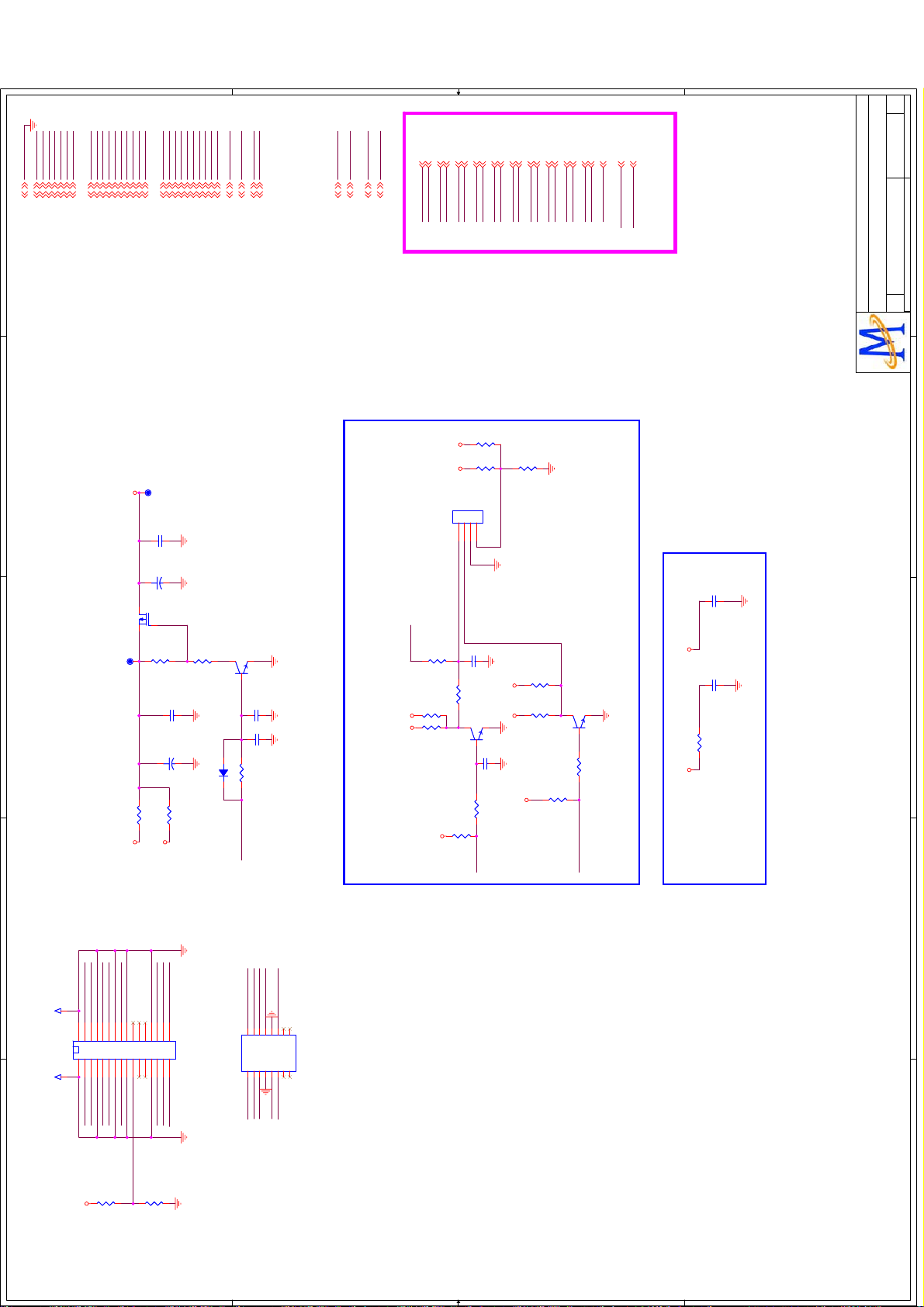
GND
E
GND3,4,5,6,7,8,9,10,11,13,14
D
C
+5V
+12V
+3V3SB
+5V3,6,8,10,14
+12V3,10,11,13,14
+3V3SB3,6,8,9
AV33
AV125
DV33
LVDS_PWR_ON
AV333,4,6,8,9,10,13
AV1253,4,5,8,9
DV333,4,5,6,7,11
V1
V1
V1
Rev
Rev
Rev
of
of
of
12 15Friday, December 04, 2009
12 15Friday, December 04, 2009
O1P
O0N
O0P
O2N
O2P
OCKN
OCKP
O3N
AO2P
AO2N
+5V
123
BL_ON/OFF
Dimming
XR8
XR8
XR21
10k
XR21
10k
AOCKP
AOCKN
XR200XR20
XR12
XR12
4
XC7
XC7
47k
47k
XQ6
2N3904
XQ6
2N3904
1
BL_PWM
XR13 4.7kXR13 4.7k
GPIO0
AO3P
AO3N
0
NS/0
NS/0
SELECT
TJC2004-4A
TJC2004-4A
1uF
1uF
3 2
CB993
1uF
CB993
1uF
O3P
E1P
E2N
E2P
E0N
E0P
E1N
AE2P
AE2N
AE1P
AE1N
AE0P
AE0N
XR19
NS/0
XR19
NS/0
SELECT Low For Internal
SELECT Hi For External
XR22
1k/NC
XR22
1k/NC
DV33
XR18
10k
XR18
10k
+5V
XR23
XR23
+3V3SB
ECKN
ECKP
AECKP
AECKN
1K PULL UP to
3V,for 42" lcd.
XQ5
XQ5
1
XR17 4.7kXR17 4.7k
10K
10K
ADIN3
E3N
E3P
LVDSVDD
DIMMING_OUT
AE3P
AE3N
LVDSVDD
DIMMING_OUT
2N3904
2N3904
3 2
LO = > POWER_ON
HI = > POWER_OFF
BL_PWM
BL_PWM
FOR MT8282
NC14
NC14
NEAR ICNEAR IC
AVDD33_LVDS
AV33AV125
NC17
NC17
AVDD12_VPLL
0
NR40NR4
0.1uF
0.1uF
0.1uF
0.1uF
No.1-2, Innovation Rd 1, SBIP, Hsin-Chu City 300
No.1-2, Innovation Rd 1, SBIP, Hsin-Chu City 300
No.1-2, Innovation Rd 1, SBIP, Hsin-Chu City 300
MediaTek Confidential
MediaTek Confidential
MediaTek Confidential
AO0N
DIMMING_OUT
DV33
+5V
AO0P
XR61KXR6
XR5
XR5
R1837
R1837
1K
1K/nc
1K/nc
O1N
AO1P
AO1N
NS/0
NS/0
+3V3SB
DV33
CN1
CN1
O2N
O2P
OCKN
OCKP
O0N
O1N
O1P
O0P
LVDS_POWER_ON4
O0N4
O0P4
O1P4
O1N4
O2P4
O2N4
OCKP4
Q70
AO3401
Q70
AO3401
TP39TP39
E1N
E0P
E0N
O3N
O3P
E1P
E1P4
OCKN4
O3P4
O3N4
E0P4
E0N4
TP38TP38
CB152
0.1uF
CB152
0.1uF
CE51
47uF/16v+CE51
47uF/16v
+
23
1
R123
47K
R123
47K
CB154
0.1uF
CB154
0.1uF
AVDD33_LVDS
ECKP
ECKN
E2N
E2P
E1N4
E2P4
AVDD12_VPLL
E3P
E3N
USB_PWR_EN0
USB_PWR_ERR0
E2N4
ECKP4
ECKN4
E3P4
E3N4
AVDD33_LVDS3,4,6,8,9,10,13
AVDD12_VPLL4
USB_PWR_EN04,6
USB_PWR_ERR04,6
XQ4
2N3904
XQ4
2N3904
3 2
47K
47K
1
R124
R124
CB155
0.1uF/NC
CB155
0.1uF/NC
ADIN3
ADIN34
GPIO0
BL_ON/OFF
DIMMING
GPIO04
BL_ON/OFF14
DIMMING14
AUO 120Hz =3.3V
CE49
220uF/16v+CE49
220uF/16v
R1 0/NCR1 0/NC
+5V LVDSVDD
+
R2 0R2 0
+12V
C657
C657
4.7uF/10v
4.7uF/10v
D6 1N4148D6 1N4148
R125 100KR125 100K
LVDS_PWR_ON
HI = > LVDS POWER ON
LO = > LVDS POWER OFF
INVERTOR POWER
12 15Friday, December 04, 2009
By Ray
Drawn
Drawn
Drawn
TEL:(03)567-0766 FAX:(03)578-7610
TEL:(03)567-0766 FAX:(03)578-7610
TEL:(03)567-0766 FAX:(03)578-7610
MediaTek Inc.
MediaTek Inc.
MediaTek Inc.
E
MT5305A P1V1
LVDS/BACKLIGHT
MT5305A P1V1
LVDS/BACKLIGHT
MT5305A P1V1
LVDS/BACKLIGHT
Document Number
Document Number
Document Number
Date: Sheet
Date: Sheet
Date: Sheet
Size
Size
Size
Title
Title
Title
C
C
C
D
C
B
A
O1P
O2P
O0P
O3P
OCKP
T18T18
CND1
CND1
1 2
3 4
5 6
7 8
9 10
11 12
13 14
15 16
O0N
DV33
17 18
O1N
O2N
O3N
OCKN
R1834
NS/10K
R1834
NS/10K
4 4
T19T19
LVDS CONN.
DIMMING_OUTBL_PWM
LVDSVDD
LVDSVDD
2019
22
21
23 24
25 26
27 28
29 30
31 32
PWM IN
LVDSVDD
LVDSVDD
R18350R1835
0
FOR LVDS FORMATE SELECT
ECKP
246
8
101214
A2006WV0-16X2
A2006WV0-16X2
CND2
CND2
135791113
E0N E0P
E1N E1P
E2N E2P
ECKN
16
15
8X2 2mm
8X2 2mm
E3N E3P
PWM IN and DIMMING OUT will be used to DCR of PANEL.
3 3
B
A
2 2
1 1
Page 43

V1
V1
V1
Rev
Rev
Rev
of
of
GND
AV33
+12V
TUNER_DATA
IF_AGCT
TUNER_CLK
VIN_ATV
VIP_ATV
AVDD33_SIF
AVDD33_DEMOD1
AVDD33_DIG
of
13 15Friday, November 27, 2009
13 15Friday, November 27, 2009
13 15Friday, November 27, 2009
Drawn
Drawn
Drawn
1
GND3,4,5,6,7,8,9,10,11,12,14
2
3
4
+12V3,10,11,12,14
AV333,4,6,8,9,10,12
Title
Title
Title
TUNER
TUNER
TUNER
1
MT5305A P1V1
MT5305A P1V1
MT5305A P1V1
Document Number
Document Number
Document Number
C
C
C
Date: Sheet
Date: Sheet
Date: Sheet
Size
Size
Size
2
3
4
TEL:(03)567-0766 FAX:(03)578-7610
No.1-2, Innovation Rd 1, SBIP, Hsin-Chu City 300
TEL:(03)567-0766 FAX:(03)578-7610
No.1-2, Innovation Rd 1, SBIP, Hsin-Chu City 300
TEL:(03)567-0766 FAX:(03)578-7610
No.1-2, Innovation Rd 1, SBIP, Hsin-Chu City 300
MediaTek Confidential
MediaTek Confidential
VIP_ATV4
AVDD33_SIF3,4,6,8,9,10,12
AVDD33_MPX4
IF_AGCT4
AVDD33_DIG3,4,6,8,9,10,12
TUNER_CLK4
TUNER_DATA4
VIN_ATV4
+5V_TUNER
ZR4
4.7K
ZR4
4.7K
ZR3
4.7K
ZR3
4.7K
TUNER_DATA
TUNER_CLKtuner_scl_T
ZR10 100ZR10 100
ZR9 100ZR9 100
Near Tuner
tuner_sda_T
VIN_ATV
VIP_ATV
C802
100pF/NC
C802
100pF/NC
C804
100pF/NC
C804
C800 10nFC800 10nF
100
100
DFAT_IN+
L153220nHL153220nH
L152 220nHL152 220nH
C801
C801
L154
390nH/NC
L154
390nH/NC
33pF
33pF
L158
330nH
L158
330nH
R1839
R1839
L1
330nH/NCL1330nH/NC
100
100
100pF/NC
C806 10nFC806 10nF
L157
L157
L156 220nHL156 220nH
DFAT_IN-
220nH
220nH
C810
C810
C2NCC2
20090612
IF_AGCTIF_AGC
Near IC
20090612
ZR26
ZR26
10K
10K
47nF
47nF
ZC32
ZC32
C798 27pFC798 27pF
ZC7
33pF
ZC7
33pF
ZC6
33pF
ZC6
33pF
ZR11 4.7kZR11 4.7k
ZC8
ZC8
IF_T_AGC
Near Tuner
10nF
10nF
C811
180pF
C811
180pF
R1838
R1838
Near Tuner Near MT538X
C1NCC1
NC
LQM18NNR39K00
ZFB150ZFB15
0
ZFB14
ZFB14
NC/0603
NC/0603
ZFB13
ZFB13
NC/0603
Use muRata Inductor and TDK Capacitor
muRata: LQM18NNR22K00
C807 27pFC807 27pF
180pF
180pF
NC
ZFB12
ZFB12
ZFB110ZFB11
ZFB10
ZFB10
ZFB9
ZFB9
ZFB8
ZFB8
ZFB7
ZFB7
ZFB6
ZFB6
NC/0603
NC/0603
NC/0603
0
NC/0603
NC/0603
NC/0603
NC/0603
NC/0603
NC/0603
NC/0603
NC/0603
NC/0603
NC/0603
+5V_TUNER+12V
CB398
CB398
AVDD33_DEMOD1
NEAR ICNEAR ICNEAR IC
AV33AV33 AV33
AVDD33_SIF
AVDD33_DIG
0.1uF
0.1uF
ZR150ZR15
0
ZC50
0.1uF
ZC50
0.1uF
AVSS33_DEMOD1
ZC47
0.1uF
ZC47
0.1uF
AVSS33_SIF
ZC44
0.1uF
ZC44
0.1uF
AVSS33_DIG
MediaTek Confidential
MediaTek Inc.
MediaTek Inc.
MediaTek Inc.
U9
7805U97805
3
ZR6 0ZR6 0
ZR8 0ZR8 0
IF_T_AGC
DFAT_IN+
DFAT_IN-
tuner_scl_T
tuner_sda_T
8
3
6
5
10
11
9
4
NC
NC
DIF
DIF
SCL
SDA
AS_IF
IF AGC
5
D D
C C
+5V IF
7
FB
ZFB5FBZFB5
+5V_TUNER
CB399
CB399
0.1uF
0.1uF
+
+
ZC9
ZC9
NC
1
47uF/16v
47uF/16v
NC
2
GND12GND13GND14GND
15
TU1
DVT-8ADC/GW41F2
TU1
DVT-8ADC/GW41F2
B B
OUT
GND
2
IN
1
CB197
CB197
0.1uF
0.1uF
POWER SUPPLY +5V FOR TUNER
TUNER POWER +5V_TUNER
5
A A
Page 44
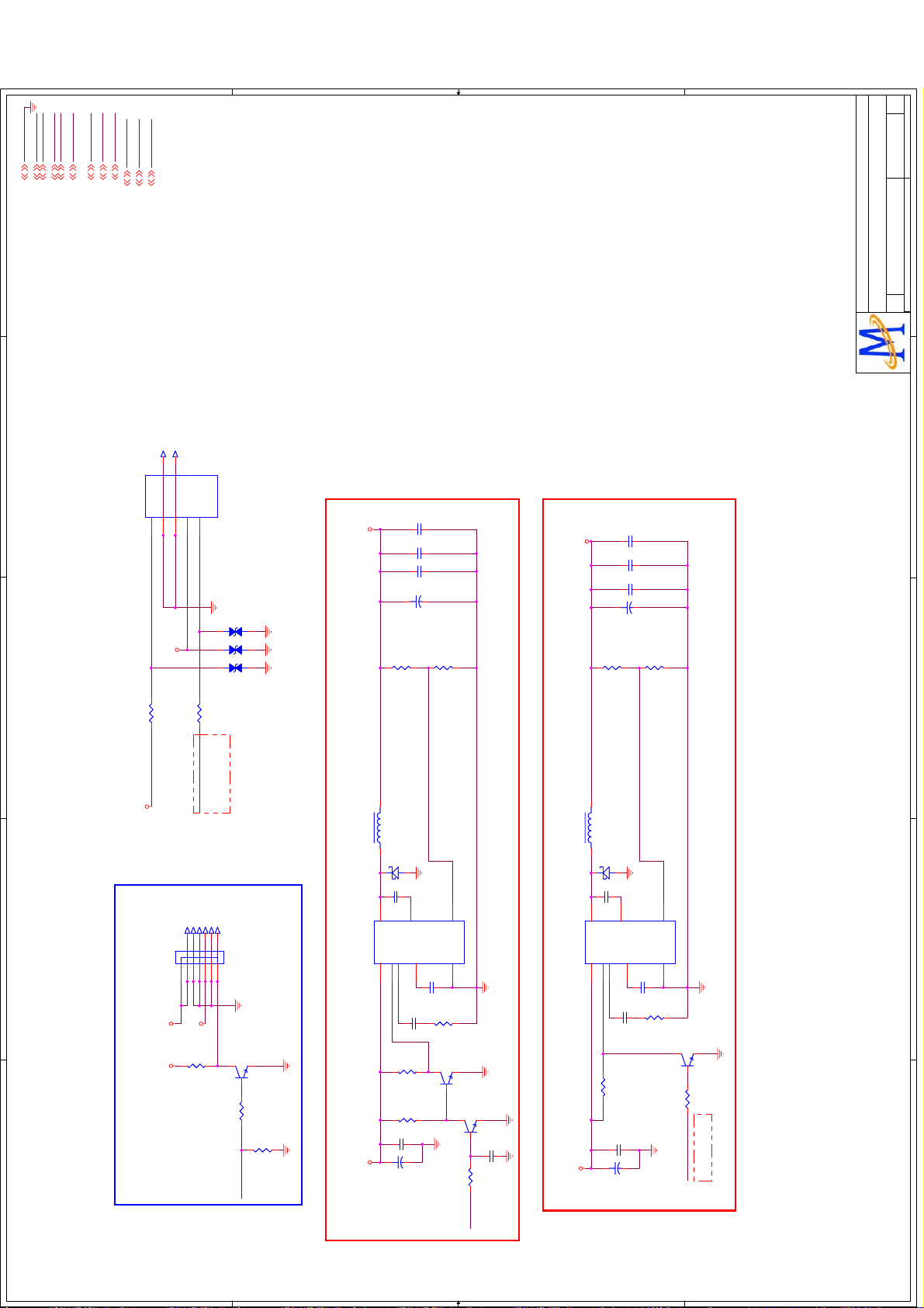
GND
GND3,4,5,6,7,8,9,10,11,12,13
1
2
+5VSB
+5VSB3,6,9
+3V3SB
+3V3SB3,6,9
+12V
+5V
+12V3,10,11,12,13
+5V3,6,8,10,12
OPWRSB
OPWRSB4
OPCTRL2
VCCK
ADIN4
VCCK3,4
ADIN44
OPCTRL24,6
DVD POWER SUPPLY
DIMMING
DIMMING12
OPWM2
BL_ON/OFF
OPWM212
BL_ON/OFF12
CN6
CN6
5
T12T12
+5V_DVD
V1
V1
V1
Rev
Rev
Rev
of
of
of
14 15Monday, March 29, 2010
14 15Monday, March 29, 2010
14 15Monday, March 29, 2010
By Ray
Drawn
Drawn
Drawn
MediaTek Confidential
MediaTek Confidential
MediaTek Confidential
TEL:(03)567-0766 FAX:(03)578-7610
No.1-2, Innovation Rd 1, SBIP, Hsin-Chu City 300
TEL:(03)567-0766 FAX:(03)578-7610
No.1-2, Innovation Rd 1, SBIP, Hsin-Chu City 300
TEL:(03)567-0766 FAX:(03)578-7610
No.1-2, Innovation Rd 1, SBIP, Hsin-Chu City 300
MediaTek Inc.
MediaTek Inc.
MediaTek Inc.
T11T11
GND3GND4+12V
STB1+5V
DVD_PWR
DVD_PWR
2
ESD_0402_10pF
ESD_0402_10pF
ESD_0402_10pF
ESD_0402_10pF
12
D14
D14
12
D13
D13
12
10nF
10nF
CPC30
CPC30
0.1uF
0.1uF
CPC29
CPC29
1uF
1uF
CPC28
CPC28
CPC31
CPC31
+
+
470UF/16V
470UF/16V
R4
12K_1%
R0603/SMD
R4
12K_1%
R0603/SMDR72.7K_1%
R7
R0603/SMD
2.7K_1%
R0603/SMD
+5V_DVD
R5
R5
CPC37
CPC37
CPC32
CPC32
CPC38
CPC38
+
+
CPC34
CPC34
12K_1%
R0603/SMD
12K_1%
R0603/SMD
10nF
10nF
0.1uF
0.1uF
1uF
1uF
220uF/16v
220uF/16v
R9
R9
2.7K_1%
R0603/SMD
2.7K_1%
R0603/SMD
1
MT5305A P1V1
MT5305A P1V1
MT5305A P1V1
BACK LIGHT/MAIN POWER
BACK LIGHT/MAIN POWER
BACK LIGHT/MAIN POWER
Document Number
Document Number
Document Number
C
C
C
Date: Sheet
Date: Sheet
Date: Sheet
Size
Size
Size
Title
Title
Title
2
3
4
5
+12V_DVD
CPR14 0
R1206/SMD
CPR14 0
R1206/SMD
R3 1KR3 1K
CNA1
CNA1
5V&12V
+12V
+5VSB
ADIN4
T6T6
T4T4
T5T5
+5VSB
XR71KXR7
1K
+12V
MAIN POWER
Hi : DVD Work
Lo : DVD Standby
T2T2 D12 ESD_0402_10pFD12 ESD_0402_10pF
T3T3
T1T1
TJC3-7A
SIP-7P-2.5/HAIER_W
TJC3-7A
SIP-7P-2.5/HAIER_W
1234567
SW_POWER
1
XQ2
XQ2
OPWRSB
LO = > POWER_ON
HI = > STANDBY
XR10
XR10
3 2
2N3904
2N3904
4.7K
4.7K
XR14
XR14
0.925 x (1+Rup/Rdn) = 5.04V
L5_9
L5_9
12
10uH/3A
CPU1
CPU1
10uH/3A
L3
L3
3
MP1484
MP1484
2
C19
C19
OUT
VCC
7
shielding of 20-mil GND
D3
B340/NCD3B340/NC
10nF
10nF
1
5
FB
BST
EN
6
GND
SS8COMP
4
C18
0.1uF
C18
0.1uF
R8
C4
2.2KR82.2K
10nFC410nF
5V MAIN POWER
R89
100K
R89
100K
Q4
2N3904Q42N3904
3 2
1
R21
100K
R21
100K
C13
0.1uF
C13
47K
47K
0.1uF
+
+
+12V +5V
CE649
CE649
220uF/16V
220uF/16V
Q3
1
R20 10KR20 10K
VCCK
2N3904Q32N3904
3 2
C3
0.1uFC30.1uF
L5_9
L5_9
12
10uH/3A
10uH/3A
L4
L4
D11
B340/NC
D11
B340/NC
C21
10nF
C21
10nF
1
3
BST
OUT
CPU2
MP1484
CPU2
MP1484
EN
VCC
SS8COMP
7
2
6
C20
C20
C5
10nFC510nF
R10
R10
DVD 5V POWER (OPTION)
R90 100KR90 100K
C14
0.1uF
C14
0.1uF
+
+
+12V
CE2
CE2
220uF/16V
220uF/16V
0.925 x (1+Rup/Rdn) = 5.04V
shielding of 20-mil GND
5
FB
GND
4
0.1uF
0.1uF
2.2K
2.2K
Q46
2N3904
Q46
2N3904
3 2
1
R91 10KR91 10K
Lo : DVD PowerOn
Hi : DVD PowerOff
OPWM2
3
4
5
D D
C C
B B
A A
Page 45
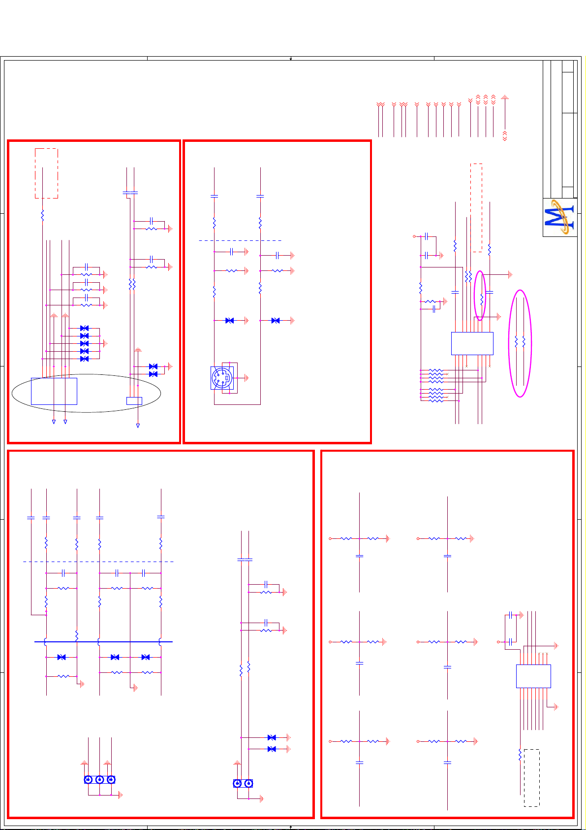
1
ADIN5
Hi : No disk load
Hi->Lo->Hi : Disk loaded
R1850 1KR1850 1K
DVD_Y_IN#
DVD_PB_IN#
DVD_PR_IN#
2
5IR7
1
4
3
2
Y_IN
GND
PB_IN
DETECT
Inner DVD &L/R INPUT
3
T10T10
6
PR_IN
DVD_IR
GND
12
12
12
12
12
T9T9
D83D83
D82D82
D78D78
D85D85
D84D84
CN13
CN13
DVD_YPbPr_IN
DVD_YPbPr_IN
BC32 15pFBC32 15pF
BR42 75BR42 75
BC31 15pFBC31 15pF
BR41 75BR41 75
BC33 15pFBC33 15pF
BR43 75BR43 75
DVD_L#
DVD_R#
GC16 2.2uFGC16 2.2uF
GC17 2.2uFGC17 2.2uF
OC26
560pF
OC26
560pF
47K
47K
GR23
GR23
OC25
560pF
OC25
560pF
47K
47K
GR24
GR26 10KGR26 10K
GR25 10KGR25 10K
DVD_L_IN
DVD_R_IN
123
DVD_LR_IN
DVD_LR_IN
GR24
D73D73
12
12
D72D72
CN14
CN14
T13T13
NEARLY CONNECTOR
SY0
SC1
47nF
SC1
47nF
SR12
100
SR12
100
NEARLY VGA CON. NEARLY IC
SR11 0SR11 0
12
SY0_IN
34
P6 S-VdieoP6 S-Vdieo
2 5
SV INPUT
SC2
47pF
SC2
47pF
SR1375SR13
75
SD3
ESD_0402_10pF
SD3
ESD_0402_10pF
61
7
SC3
47nF
SC3
47nF
SR14
100
SR14
100
SR15 0SR15 0
12
SC0_IN SC0
SC4
47pF
SC4
47pF
SR1675SR16
75
SD2
ESD_0402_10pF
SD2
ESD_0402_10pF
OPWM0 4,7
OPWM1 4,7
DVD_IR 6
AIN4_L
AIN4_R
AV33
SY0
SC0
ADIN5
SOY1
Y1P
Y1P
SOY1
AIN4_R
AIN4_L
AV33
SY0
SC0
AV33
SV Audio Shares with AV2(Horizotal),which input to AIN0_L/R
ADIN5
BR44 10KBR44 10K
C672
10uF/10v
C672
10uF/10v
C931
0.1uF
C931
0.1uF
BR45
10K
BR45
10K
C673
C673
JRN3
47K
JRN3
47K
12
34
56
78
12
34
56
78
47K
47K
JRN2
JRN2
COM1
10uF/10v
10uF/10v
OPCTRL3
COM1
PR1P
PB1P
PR1P
PB1P
OPCTRL3
OPWM0
OPWM1
DVD_IR
AIN4_R
OPWM0
OPWM1
OPWM1/OPWM0=(0/0) YPbPr2 Audio =>AIN4_L/R;
OPWM1/OPWM0=(0/1) DVD Audio =>AIN4_L/R;
BR40 1KBR40 1K
BR13 10KBR13 10K
BR11 10KBR11 10K
GC13 2.2uFGC13 2.2uF
BR47 NCBR47 NC
13
16
9
8
6
A10B
INH
VCC
GND7GND
1-COM
2Y342Y1
1Y2151Y1
1Y0121Y3
2
14
11
Y2_R#
DVD_R#
U67
U67
AIN4_L
BR3 1KBR3 1K
GC12 2.2uFGC12 2.2uF
3
2-COM
2Y012Y2
Y2_L#
5
DVD_L#
GND
GND4,5,6,7,8,9,10,11,12,13,14
AIN4_L
74LV4052D
74LV4052D
BR48 0/NCBR48 0/NC
Y2_L#
MediaTek Confidential
MediaTek Confidential
MediaTek Confidential
No.1-2, Innovation Rd 1, SBIP, Hsin-Chu City 300
No.1-2, Innovation Rd 1, SBIP, Hsin-Chu City 300
No.1-2, Innovation Rd 1, SBIP, Hsin-Chu City 300
AIN4_R
BR49 0/NCBR49 0/NC
Y2_R#
without InnerDVD:
BR48/BR49 should be SMT ;74HC4052 will be NC.
V1
V1
V1
Rev
Rev
Rev
of
of
of
15 15Friday, December 04, 2009
15 15Friday, December 04, 2009
15 15Friday, December 04, 2009
Drawn
Drawn
Drawn
TEL:(03)567-0766 FAX:(03)578-7610
TEL:(03)567-0766 FAX:(03)578-7610
TEL:(03)567-0766 FAX:(03)578-7610
MediaTek Inc.
MediaTek Inc.
MediaTek Inc.
1
MT5305A P1V1
MT5305A P1V1
MT5305A P1V1
DVD/YPbPr2/S_video Input
DVD/YPbPr2/S_video Input
DVD/YPbPr2/S_video Input
Document Number
Document Number
Document Number
C
C
C
Date: Sheet
Date: Sheet
Date: Sheet
Size
Size
Size
Title
Title
Title
2
with InnerDVD:
BR48/BR49 resistor will be NC; 74HC4052 will be SMT.
3
SOY1
Y1P
BC31.5nF BC31.5nF
BC410nF BC410nF
BR568BR5
NEARLY ICNEARLY YPBPR CON.
68
4
5
BR418 BR418
Y2_SWO
BL1
80/100MHZ/NC
BL1
80/100MHZ/NC
12
Y_IN#2
YPBPR/RL#2 INPUT
COM1
PB1P
BC710nF BC710nF
BC610nF BC610nF
BR1068 BR1068
BR8100 BR8100
BC5
15pF
BC5
15pF
BR656BR6
56
Connected to connector GND
BR918 BR918
PB2_SWO
BR70 BR70
BD3
BD3
ESD_0402_10pF
ESD_0402_10pF
BR1775BR17
75
Y_IN#2
867523
red gb
red gb
BL2
BL2
PB_IN#2
PB_IN#2
4
BC9
15pF
BC9
15pF
BR1256BR12
56
BD4
BD4
80/100MHZ/NC
80/100MHZ/NC
ESD_0402_10pF
ESD_0402_10pF
12
BR2975BR29
75
PR_IN#2
BP1
BP1
1
RCA3X1
RCA3X1
BC11
15pF
BC11
15pF
BR1456BR14
56
BD5
BD5
ESD_0402_10pF
ESD_0402_10pF
12
BR3075BR30
75
PR1P
BC1210nF BC1210nF
BR1668 BR1668
BR1518 BR1518
PR2_SWO
80/100MHZ/NC
80/100MHZ/NC
BL3
BL3
without InnerDVD:
PR_IN#2
Y2_L#
Y2_R#
GC14 2.2uFGC14 2.2uF
GC15 2.2uFGC15 2.2uF
OC24
OC24
47K
47K
GR13
GR13
OC23
OC23
47K
47K
GR14
GR14
NEARLY CONNECTOR
75ȍ resistor will be NC;
5V330 video switch will be NC;
with InnerDVD:
BL1/BL2/BL3 will be NC ;
BP2
BP2
RCA2X1
RCA2X1
GR21 10KGR21 10K
GR22 10KGR22 10K
YPBPR_L_IN#2
YPBPR_R_IN#2
4
2
redw
redw
1
3 5
12
12
560pF
560pF
560pF
560pF
BD2
BD2
ESD_0402_10pF
ESD_0402_10pF
BD1
BD1
ESD_0402_10pF
ESD_0402_10pF
AV33
AV33 AV33
R1853
R1853
R1859
R1859
R1858
R1858
10K
10K
10K
10K
10K
10K
CE658
CE658
PR_IN#2
PB_IN#2_SW
CE656
CE656
CE654
CE654
Y_IN#2 PB_IN#2Y_IN#2_SW PR_IN#2_SW
R1862
10K
R1862
10K
10uF/10V
10uF/10V
R1860
10K
R1860
10K
10uF/10V
10uF/10V
R1857
10K
R1857
10K
10uF/10V
10uF/10V
AV33AV33
AV33
R1855
R1855
R1854
R1854
R1851
R1851
10K
10K
10K
10K
10K
10K
DVD_PR_IN#_SWDVD_Y_IN#
CE659
CE659
DVD_PR_IN#
CE657
CE657
DVD_Y_IN#_SW DVD_PB_IN# DVD_PB_IN#_SW
CE655
CE655
R1861
10K
R1861
10K
10uF/10V
10uF/10V
R1852
10K
R1852
10K
10uF/10V
10uF/10V
R1856
10K
R1856
10K
10uF/10V
10uF/10V
AV33
C671
C671
CB1005
0.1uF
CB1005
0.1uF
10uF/10v
10uF/10v
U53
U53
16
15
E#
VCC
I0A2I1A3S1YA4I0B5YB7GND
Y_IN#2_SW
YPBPR2/DVD_SEL
SR18 10KSR18 10K
OPCTRL3
YPbPr2 & DVD VIDEO SWITCH
4
PR_IN#2_SW
DVD_PR_IN#_SWY2_SWO
12
9
14
11
10
YD
YC
I0D
I1D13I0C
I1C
I1B
PI5V330
PI5V330
6
8
PB_IN#2_SW PR2_SWO
DVD_PB_IN#_SW
DVD_Y_IN#_SW
PB2_SWO
5
OPCTRL3=1::DVD
OPCTRL3=0::YPBPR2
D D
C C
B B
A A
Page 46
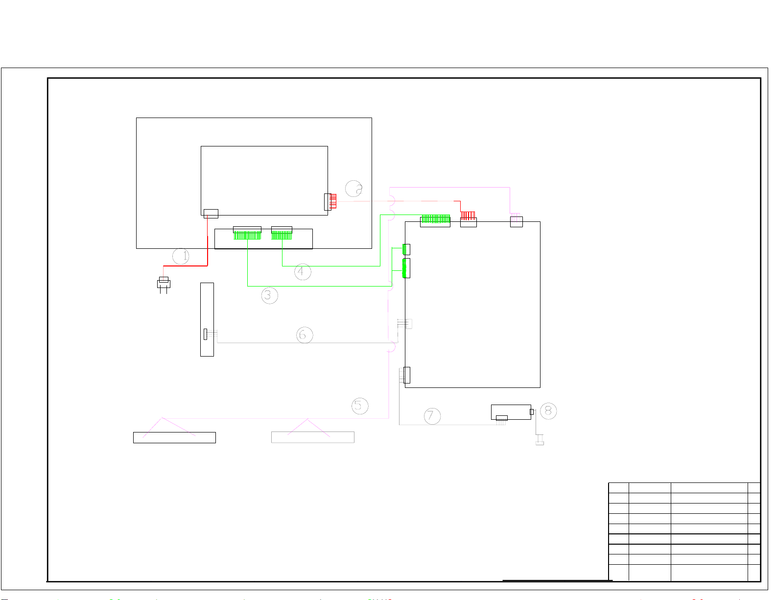
PANEL
Power Cord
POWER
SUPPLY
PD801
Keypad Assembly
JP1
Speaker
CN2
CN1
Connection Wire(Control
CNM801
LVDS Wire
LVDS Wire
)
Speaker Wire
Connection
Wire(12V/5V )
CN4
CN8
CN5
CN10
Mainboard
Assembly
CNB3
CNB4
Remote Control Board
Assembly
Connection Wire(Remote
CN27
CNE2 CNE3
)
Connection Wire(Lamp
)
8
0090402750
7
6
5
4
3
2
1
NO.
Connection Wire(Lamp)
Connection Wire(Remote
Connection Wire(Control
Speaker Wire
LVDS Wire
LVDS Wire
Connection Wire(12V/5V )
Power Cord
NAME
)
)
1
1
1
1
1
1
1
1
QTY
Page 47
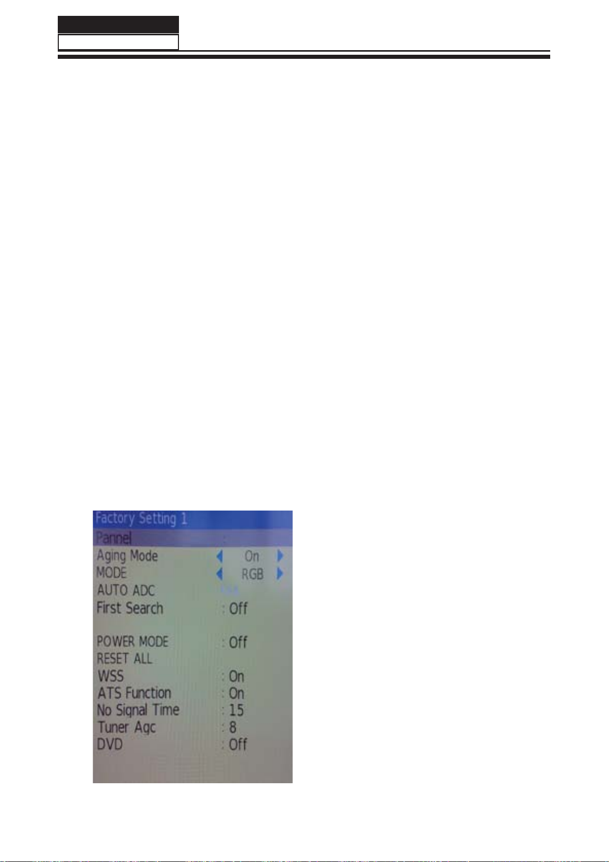
Service Manual
Model No.: LEA40T3
Chapter 8. Measurements and Adjustments
8-1. Service Mode
8-1-1.How to enter into Service Mode
The way to the factory mode menu:
1st, press menu,
2en, input 8893,
Finished these operations ,system will be into the factory mode menu.
At the end of the main factory menu, you can see the edition of the software,
like this” L_MSD209_AU32 ”.
8-1-2.How to exit
If you want to exit this factory menu, please press the button ”Exit” on the remote.
system will be out the factory mode menu.
8-2. Measurements and Adjustments
8-2-1. The Main Menu
In factory mode menu,press up/down button to choose the up/down item,press left/right button
to the submenu,press "OK"button to affi rm .press MENU button go to the next page.
MSD209 Factory Menu
In this page, you just consider "RESET
ALL" function.This function you can reset all
date return to factory state.if you encounter
inextricable problem,you can try this function.
Press
ALL",press "OK" button.It needs a few
secounds.
NOTE : After reset ,please shut off the power.
Be carefully use this function.
up/down button to select "RESET
46
Page 48
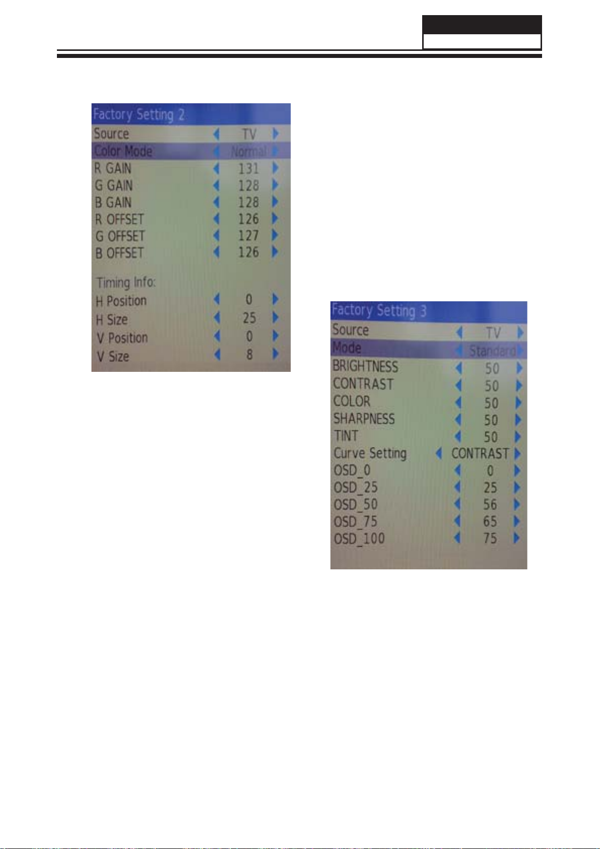
8-2-2. Video
Service Manual
Model No.: LEA40T3
Color Temperature
This page is control the Color Temperature,
and the picture size.
Picture Mode
This page is control the picture effect , like
Brightness,contrast,color,sharpness.
47
Page 49

Service Manual
Model No.: LEA40T3
8-2-3. Audio
This page is control the sound effect ,from
100Hz to 10KHz.
8-2-4. Software UpDate
In this page , you just consider the software
update function.Plug USB into the 1st USB port
,select "SOFTWARE UPDATE" press "OK", Then
flip the other window,perss "OK",The update is
going work.
48
NOTE : After software update ,turn to the Factory
Setting 1 page reset all.
Page 50

Chapter 9. Trouble shooting
9-1. Simple check
Verify if the television is properly plugged
No picture/ No sound
Blank screen
Verify if the television is properly supplied power
Verify if electricity is available.
Verify if correct signals are input
Press INPUT button to change signal input to TV input
Restart the television of power supply is interrupted
Service Manual
Model No.: LEA40T3
No sound
Poor sound
No picture in some channel
No color for some channel program
(black and white)
Spots with some or all pictures
Press Mute button and verify if Mute mode is set.
Switch to otger channel and verify if the same problem
happens.
Press VOL+ button to see of he problem can be solved.
Verufy if sound system is correct .Refer to some chapter for
adjust.
Verify if correct channel is selected.
Adjust the antenna.
Make adjustments by Fine Tune and MANUAL Scan.
Verify if the same problem exists in other channels.
check out of picture and sound system.
Refer to relative instructions in the Manual for color adjust.
Verify if the antennal is correctly connected.
Verify if the antennal is in good condition.
Make fi ne adjustment of channel.
Horizontal/ vertical bars or picture
shaking
Television out of control
Check for local interference such as an electrical appliance
or power tool.
Disconnect the television from power supply and 10
seconds later, connect the television to the power supply.
If the problem still exists, contact authorized after-sales
service for technical assistance.
49
Page 51

9-3. Mainboard Failure Check
Symptom: No Sound
No Sound
(All Mode)
Service Manual
Model No.: LEA40T3
Check the input
Source
Pass
Check the
input/output
Pass
Check the
input/output
Pass
Fail
Fail
Fail
Change Source input
Re-soldering or change
IC U13
Re-soldering or change
IC U55
Check the
input/output
Pass
Check the
Speaker
Pass
Check the
Sperker wire
Fail
Re-soldering or change
IC U2
Fail
Change the Speaker
51
Page 52

Service Manual
Model No.: LEA40T3
9-4. Pannel Failure
Failure Mode
Block Defect :TCP cracking or cracking
Dim or L/D :TCP Sunken
:TCP lead cracking
:ACF bonding short
:Awful environment and
something electric enter
into LCD
:Mis-align between TCP and
Panel
:Panel failure
:TCP failure
Vertical color line(light or
dark forever)
Horizontal line(light or
dark forever)
52
V B/D Vertical bar
Part Name Description Phenomena Failure cause
V Dim Vertal gray line
V L/D
TCP
H B/D Horizontal bar
H Dim Horizontal gary line
H L/D
Page 53

Bladder between Polarizer and
top glass
Service Manual
Model No.: LEA40T3
1.Chip lose action
2.IC ahort or jointiog bad
3.Pannel and vsc connect bad
Dot Defect Bright dot dark dot in pannel Incoming Inspection Standard
Part Name Description Phenomena Failure Cause
Polarizer Bubble Bladder in Polarizer
Panel or Polarlzer
Polarizer Scratch Polarizer Scratch Tine or rigidity arose
F/inside Polarizer Eyewinker inside Polarizer Eyewinker inside Polarizer
Abnormal Display Abnormal Display
Circuit
Flashing Bright and dark display alternately
53
Page 54

Service Manual
Model No.: LEA40T3
Maybe caused by surge current and EDS
B/L normal,
only white screen display
B/L normal,
LCD
Vcom imbalance
only Black screen display
Capacitance
improper bring crosstalk inside LCD pannel
Only
color abormal
1.Chip
lose action
2.IC short or jointion bad
3.Pannel and vsc connect bad
Only
color abnormal
Part Name Description Phenomena Failure Cause
54
White Screen
Black Screen
FIIcker Crosstalk
Circuit
Abnormal Color
Abnormal Color
Page 55

Caused
by Mechanica noise of backlight unit
Causeed by
between
mechanism and pannel
*Connect
badness
between wire and electrode
*Connect
badnessShort between wire and electrode
Operation
abnormal
or systemic noise
Operation
Service Manual
Model No.: LEA40T3
abnormal
or systemic noise
Short bitween lamp housing and wire, Because
consume power too much
F/M in B/L unit
When
turn panel,appear cacophony
Nolse
Mechanlcal
Part Name Description Phenomena Failure cause
Ripple Connectric circle
B/L off B/L lose action
normal
B/L brightness darker than
B/L dark
B/L
wire damaged
B/L
wire damaged
B/L wire open Without backlight
B/L shut down B/L shutdown in sometime
F/M
or wirelike
inB/L ,white,balck Rotundity
F/M
55
Page 56

Service Manual
Model No.: LEA40T3
B/L unit badness
Sheet in B/L unit is uneven
*Lack screw
Screw damage
Brightness
at bottom of LCM brighter
Light leakage
Part Name Description Phenomena Failure Cause
than normal
Lack screw
Uniformity B/L brightness asymmetric
Mechanlcal or B/L
or screw damage
Mount hole
56
 Loading...