

Page 1

Model No.
Chassis
This service information is designed for experienced repair technicians only and is not designed for use by the general public.
It does not contain warnings or cautions to advise non-technical individuals of potential dangers in attempting to service a product.
Products powered by electricity should be serviced or repaired only by experienced professional technicians. Any attempt to service or repair
the product or products dealt with in this service information by anyone else could result in serious injury or death.
Haier Group
©2009 Qingdao Haier Electronics Co., Ltd.
All rights reserved. Unauthorized copying and distribution is a violation of law.
SERVICE MANUAL
WARNING
TV0912S012V0
MTK5305
HL42XZK42
Order No.
LCD TV
Page 2
Service Manual
Model No.: HL42XZK42
1
CONTENTS
Chapter 1: General Information..............................3
1-1. Document Information .............................................................3
1-2. General Guidelines...................................................................3
1-3. Important Notice
.......................................................................3
1-3-1. Follow the regulations and warnings ..................................................... 3
1-3-2. Be careful to the electrical shock ........................................................... 3
1-3-3. Electro static discharge (ESD)
............................................................... 3
1-3-4. About lead free solder (PbF) ..................................................................4
1-3-5. Use the genewing parts (specied parts) .............................................. 4
1-3-6. Safety check after repairment ................................................................ 4
1-3-7. Ordering Spare Parts
............................................................................. 6
1-3-8. Photo used in this manual ..................................................................... 6
1-4. How to Read this Service Manual ...........................................6
1-4-1. Using icons: ........................................................................................... 6
Chapter 2: Specication..........................................8
2-1. Specication List......................................................................8
2-2. External Pictures (four faces)..................................................9
Chapter 3. Disassemble and Assemble............... 11
3-1. Remove the Stand .................................................................. 11
3-2. Remove the Back Cover ........................................................ 11
3-4. Remove the Terminal Bracket
............................................... 11
3-5. Remove the Power Supply Module.......................................12
3-6. Remove the Mainboard
..........................................................12
3-8. Remove the Speaker ..............................................................12
3-9. Remove the Remote Control Board
......................................12
Chapter 4. Location of Controls&Components...13
4-1. Board Location .......................................................................13
4-2. Main Board & AV Board .........................................................13
4-2-1. Function Description: ........................................................................... 14
4-2-2. Connector denition ............................................................................. 14
Page 3

Service Manual
Model No.: HL42XZK42
2
4-3. Power Supply Board ..............................................................16
4-3-1. Function description:............................................................................ 16
4-3-2. Connector denition: ............................................................................ 16
4-4. LCD Panel ...............................................................................16
4-4-1. Function Description: Display the signal..............................................17
4-4-2. Connector denition: ............................................................................ 17
Chapter 5. Installation Instructions......................20
5-1. External Equipment Connections .........................................20
5-2. HDMI Connections .................................................................23
Chapter 6. Operation Instructions ........................25
6-1. Front Panel Controls ..............................................................25
6-2. Back Panel Controls ..............................................................26
6-3. Setting Up Your Remote Control
..........................................27
Chapter 7. Electrical Parts.....................................28
7-1. Block Diagram ........................................................................28
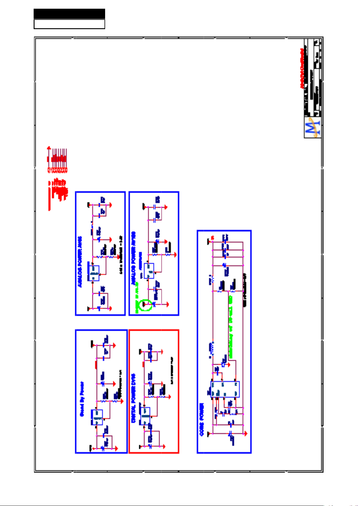
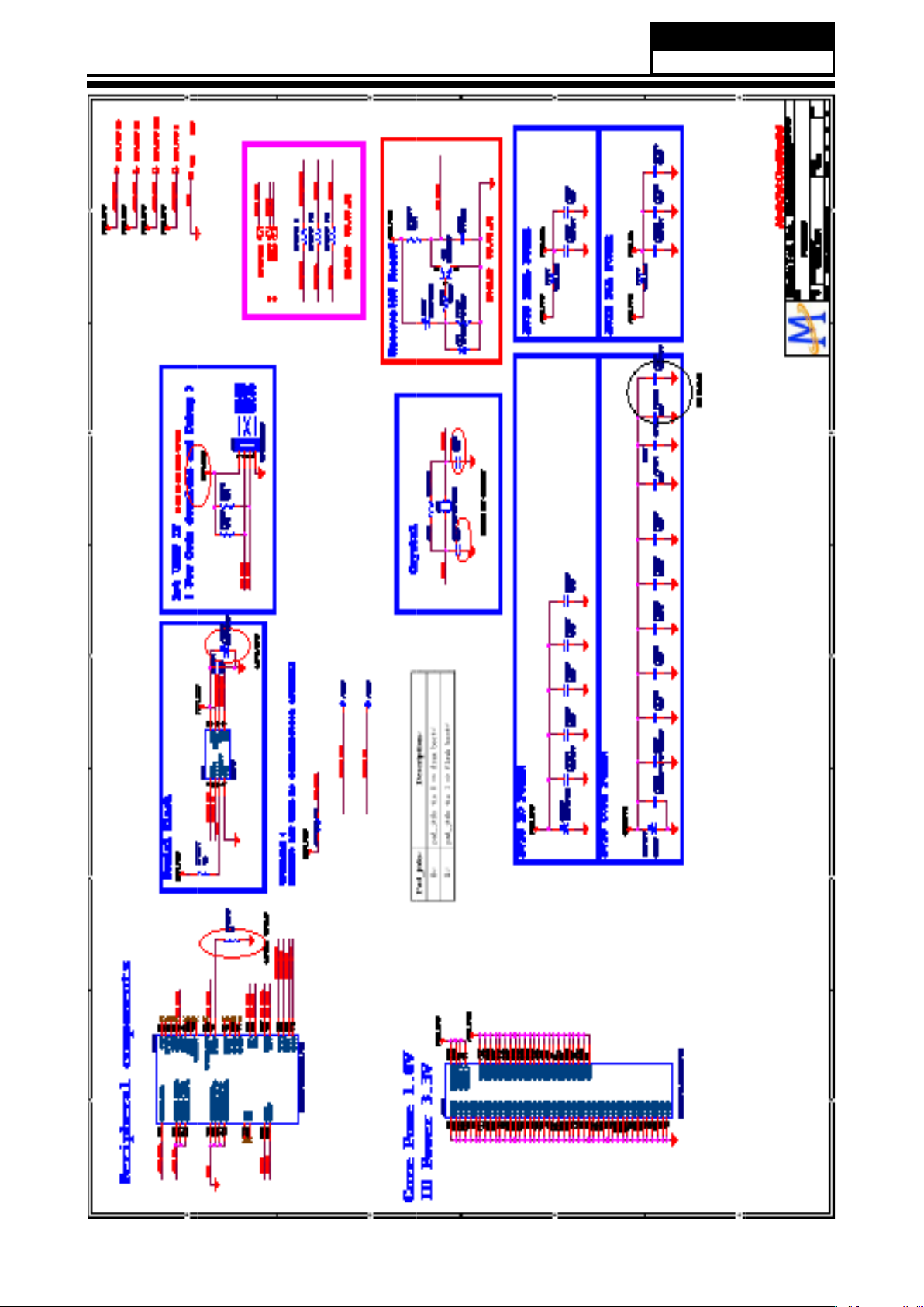
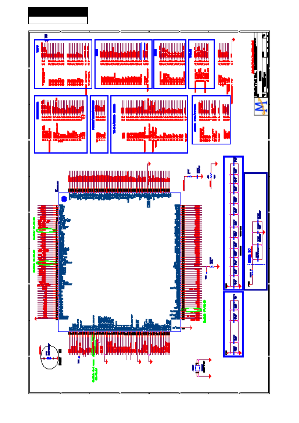
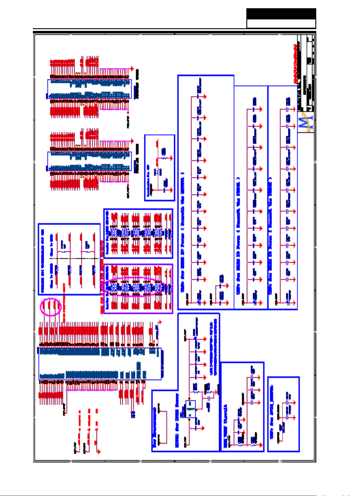
7-2. Circuit Diagram.......................................................................29
7-3. Wiring Connection Diagram
..................................................46
Chapter 8. Measurements and Adjustments........47
8-1. Service Mode .........................................................................47
8-1-1.How to enter into Service Mode............................................................ 47
8-1-2.How to exit ............................................................................................ 47
8-2. Measurements and Adjustments ..........................................47
8-2-1. Version, S/N, Panel Resoution ............................................................ 47
8-2-2. Video .................................................................................................... 48
8-2-3. Audio
.................................................................................................... 49
8-2-4. Channel ............................................................................................... 49
8-2-5. Gamma ................................................................................................ 51
8-2-6. Backlight .............................................................................................. 51
8-2-7. Function
............................................................................................... 52
Chapter 9. Trouble shooting..................................54
9-1. Simple check ..........................................................................54
9-2. Power Supply Board Failure Check......................................55
9-3. Mainboard Failure Check ......................................................56
Page 4

Service Manual
Model No.: HL42XZK42
3
Chapter 1: General Information
1-1. Document Information
Document format: Adobe PDF
Author: Zhou Peng
Compiler: Bao Qinghong
1-2. General Guidelines
When servicing, observe the original lead dress. If a short circuit is found, replace all parts which
have been overheated or damaged by the short circuit.
After servicing, see to it that all the protective devices such as insulation barriers, insulation papers
shields are properly installed.
After servicing, make the following leakage current checks to prevent the customer from being
exposed to shock hazards.
1) Leakage Current Cold Check
2) Leakage Current Hot Check
3) Prevention of Electro Static Discharge (ESD) to Electrostatically Sensitive
1-3. Important Notice
1-3-1. Follow the regulations and warnings
Most important thing is to list up the potential hazard or risk for the service personnel to open
the units and disassemble the units. For example, we need to describe properly how to avoid the
possibility to get electrical shock from the live power supply or charged electrical parts (even the
power is off).
This symbol indicates that high voltage is present inside.It is dangerous to make any
king of contact with any inside part of this product.
This symbol indicates that there are important operating and maintenance instructions
in the literture accompanying the appliance.
1-3-2. Be careful to the electrical shock
To prevent damage which might result in electric shock or re, do not expose this TV set to rain
or excessive moisture. This TV must not be exposed to dripping or splashing water, and objects
lled with liquid, such as vases, must not be placed on top of or above the TV.
1-3-3. Electro static discharge (ESD)
Some semiconductor (solid state) devices can be damaged easily by static electricity. Such
Page 5

Service Manual
Model No.: HL42XZK42
4
components commonly are called Electrostatically Sensitive (ES) Devices. The following
techniques should be used to help reduce the incidence of component damage caused by
electros static discharge (ESD).
Electrostatically Sensitive (ES) Devices
Some semiconductor (solid-state) devices can be damaged easily by static electricity. Such
components commonly are called Electrostatically Sensitive (ES) Devices. Examples of typical
ES devices are integrated circuits and some field-effect transistors and semiconductor "chip"
components. The following techniques should be used to help reduce the ncidence of component
damage caused by static by static electricity.
1. Immediately before handling any semiconductor component or semiconductor-equipped
assembly, drain off any electrostatic charge on your body by touching a known earth ground.
Alternatively, obtain and wear a commercially available discharging wrist strap device, which
should be removed to prevent potential shock reasons prior to applying power to the unit under
test.
2. After removing an electrical assembly equipped with ES devices, place the assembly on a
conductive surface such as aluminum foil, to prevent electrostatic charge buildup or exposure of
the assembly.
1-3-4. About lead free solder (PbF)
This product is manufactured using lead-free solder as a part of a movement within the
consumer products industry at large to be environmentally responsible. Lead-free solder must be
used in the servicing and repairing of this product.
1-3-5. Use the genewing parts (specied parts)
Special parts which have purposes of re retardant (resistors), high-quality sound (capacitors),
low noise (resistors), etc. are used.
When replacing any of components, be sure to use only manufacture's specied parts shown in
the parts list.
Safety Component
● Components identied by mark have special characteristics important for safety.
1-3-6 Safety check after repairment
Conrm that the screws, parts and wiring which were removed in order to service are put in the
original positions, or whether there are the positions which are deteriorated around the serviced
places serviced or not. Check the insulation between the antenna terminal or external metal and
the AC cord plug blades. And be sure the safety of that.
General Servicing Precautions
Page 6
Service Manual
Model No.: HL42XZK42
5
1. Always unplug the receiver AC power cord from the AC power source before:
a. Removing or reinstalling any component, circuit board module or any other receiver
assembly.
b. Disconnecting or reconnecting any receiver electrical plug or other electrical connection.
c. Connecting a test substitute in parallel with an electrolytic capacitor in the receiver.
CAUTION:
A wrong part substitution or incorrect polarity installation of electrolytic capacitors
may result in an explosion hazard.
2. Test high voltage only by measuring it with an appropriate high voltage meter or other voltage
measuring device (DVM, FETVOM, etc) equipped with a suitable high voltage probe.
Do not test high voltage by "drawing an arc".
3. Do not spray chemicals on or near this receiver or any of its assemblies.
4. Unless specified otherwise in this service manual, clean electrical contacts only by applying
the following mixture to the contacts with a pipe cleaner, cotton-tipped stick or comparable nonabrasive applicator; 10% (by volume) Acetone and 90% (by volume) isopropyl alcohol (90%-99%
strength).
CAUTION:
This is a ammable mixture.
Unless specied otherwise in this service manual, lubrication of contacts is not required.
Capacitors may result in an explosion hazard.
5. Do not defeat any plug/socket B+ voltage interlocks with which receivers covered by this
service manual might be equipped.
6. Do not apply AC power to this instrument and/or any of its electrical assemblies unless all
solid-state device heat sinks are correctly installed.
7. Always connect the test receiver ground lead to the receiver chassis ground before connecting
the test receiver positive lead.
Always remove the test receiver ground lead last. Capacitors may result in an explosion
hazard.
8. Use with this receiver only the test xtures specied in this service manual.
CAUTION:
Do not connect the test xture ground strap to any heat sink in this receiver.
9. Remove the antenna terminal on TV and turn on the TV.
10. Insulation resistance between the cord plug terminals and the eternal exposure metal should
be more than Mohm by using the 500V insulation resistance meter.
11. If the insulation resistance is less than M ohm, the inspection repair should be required.
If you have not the 500V insulation resistance meter, use a Tester. External exposure metal:
Antenna terminal Headphone jack.
Page 7

Service Manual
Model No.: HL42XZK42
6
3. Use only a grounded-tip soldering iron to solder or unsolder ES devices.
4. Use only an anti-static type solder removal device. Some solder removal devices not
classied as "anti-static" can generate electrical charges sufcient to damage ES devices.
5. Do not use freon-propelled chemicals. These can generate electrical charges sufficient to
damage ES devices.
6. Do not remove a replacement ES device from its protective package until immediately before
you are ready to install it.
(Most replacement ES devices are packaged with leads electrically shorted together by
conductive foam, aluminum foil or comparable conductive material).
7. Immediately before removing the protective material from the leads of a replacement ES
device, touch the protective material to the chassis or circuit assembly into which the device will
be installed.
CAUTION:
Be sure no power is applied to the chassis or circuit, and observe all other safety
precautions.
8. Minimize bodily motions when handling unpackaged replacement ES devices. (Otherwise
harmless motion such as the brushing together of your clothes fabric or the lifting of your foot
from a carpeted oor can generate static electricity sufcient to damage an ES device.)
1-3-7. Ordering Spare Parts
Please include the following informations when you order parts. (Particularly the Version letter)
1. Model number, serial number and software version
The model number and serial number can be found on the back cover of each product. Software
version can be found in the Spare Parts List.
2. Spare part No. and description
Spare part No. and description can be found in the Spare Parts List.
1-3-8. Photo used in this manual
The illustration and photos used in this Service Manual may not base on the final design of
products, which may differ from your products in some way.
1-4. How to Read this Service Manual
1-4-1. Using icons:
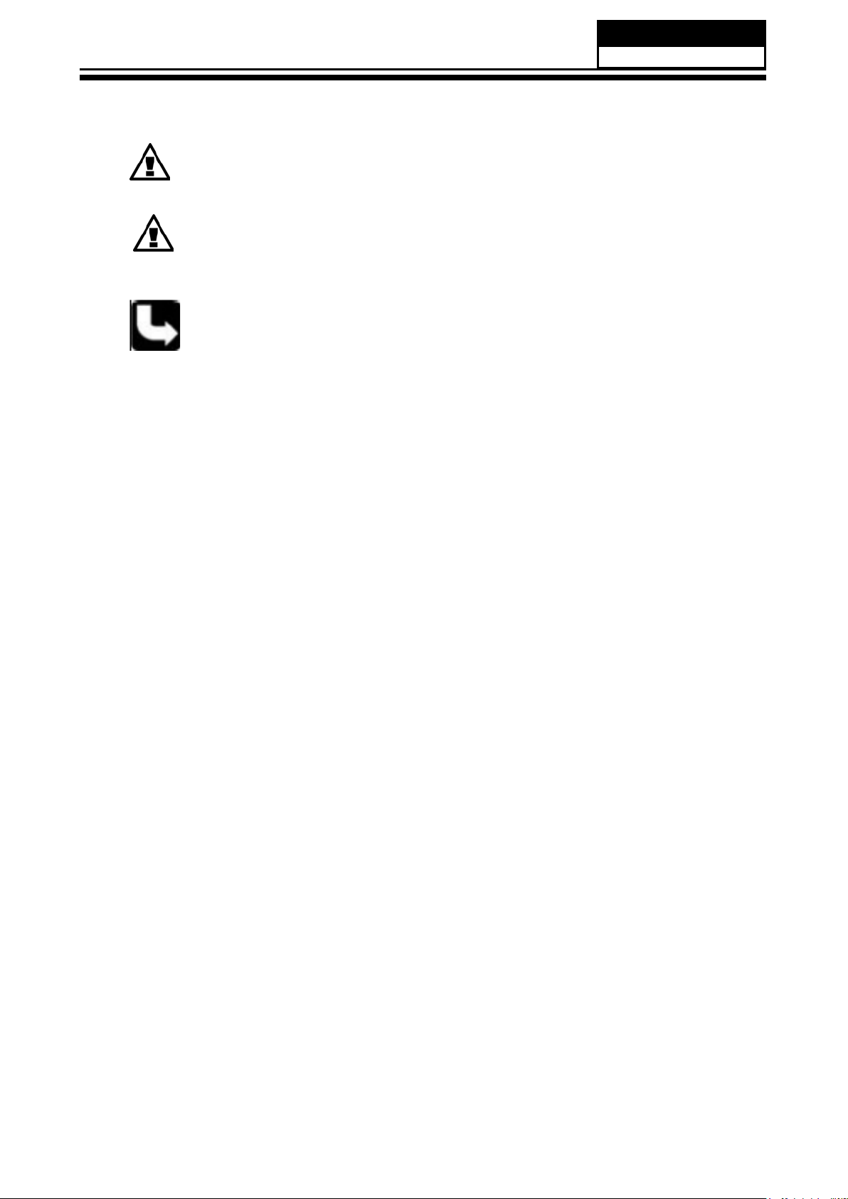
Icons are used to attract the attention of the reader to specic information. The meaning of each
icon is described in the table below:
Note:
A “note” provides information that is not indispensable, but may nevertheless be
valuable to the reader, such as tips and tricks.
Page 8
Service Manual
Model No.: HL42XZK42
7
Caution:
A “ caution” i s use d when there is d a n g e r tha t the reader, t h r o u gh in c o r r e c t
manipulation, may damage equipment, loose data, get an unexpected result or has to
restart(part of) a procedure.
Warning:
A “warning” is used when there is danger of personal injury.
Reference:
A “reference” guides the reader to other places in this binder or in this manual, where
he/she will nd additional information on a specic topic.
Page 9
Service Manual
Model No.: HL42XZK42
8
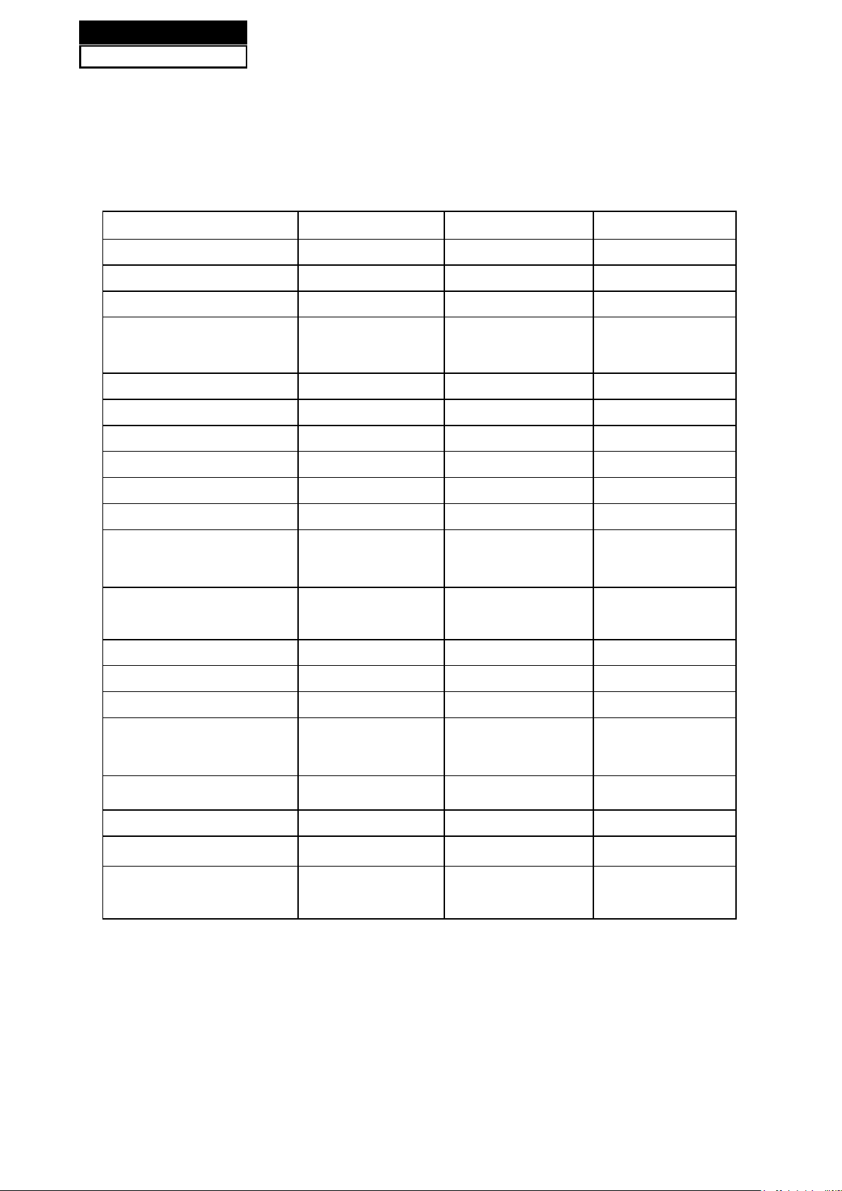
Model HL42XZK42
Screen Size 42 inch
Aspect Ratio 16:9
Resolution 1920x1080
Response Time (ms)
8(GRAY TO
GRAY)
Angel of View 176o
Color Display 16777216
No. of Preset Channels 181
OSD Language
English/French/Spanish
Color System NTSC
Audio System M, BG, I, L, L'
Audio Output Power
(Built-in) (W)
10W×2
Audio Output Power
(outer) (W)
No
Total Power Input (W) 200W
Voltage Range (V) AC120V~
Power Frequency (Hz) 60Hz
Time of Sleep Timer
(MINS)
120Min
Net Weight (KG) 25.5
Gross Weight (KG) 30
Net Dimension (MM) 1020x290x724
Packaged Dimension
(MM)
1120x360x795
Chapter 2: Specication
2-1. Specication list
Page 10

Service Manual
Model No.: HL42XZK42
9
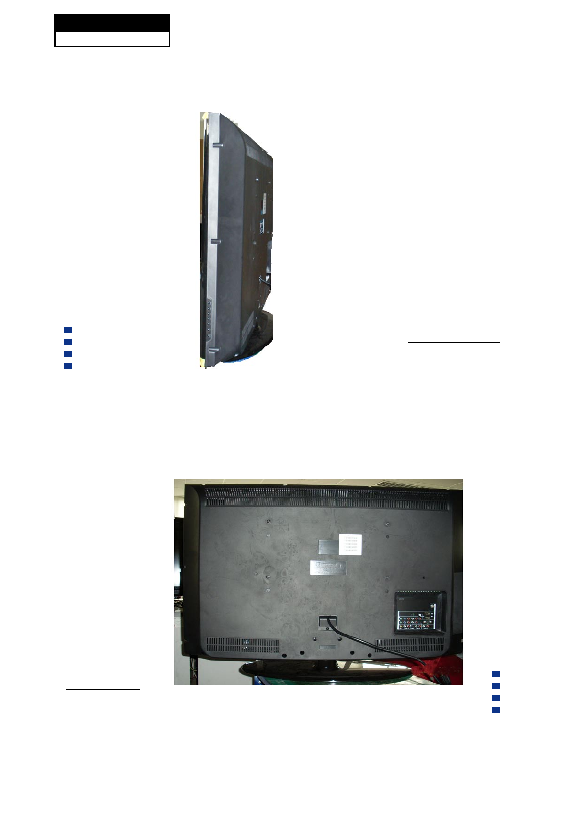
2-2 External pictures (four faces)
Front Side
Left Side
Page 11
Service Manual
Model No.: HL42XZK42
10
Right Side
Back Side
Page 12

Chapter 3. Disassemble and Assemble
3-1 Remove the Stand
1. Lay down the unit so that back cover faces
upward
2. Remove the six scr ews from t he back
cover which are indicated with the circles in the
picture above.
3. Remove the stand
3-2. Remove the Back Cover
1. Remove the thirteen screws indicated (See
picture right.)
2. Then remove the back cover from the
unit.
3-3. Remove the Adhesive Tape
The location of the adhesive tape is shown
below.
Remove the adhesive tape.
Remove the two screws indicated by the
red circles in the picture. (See next page.)
Service Manual
Model No.: HL42XZK42
11
Page 13
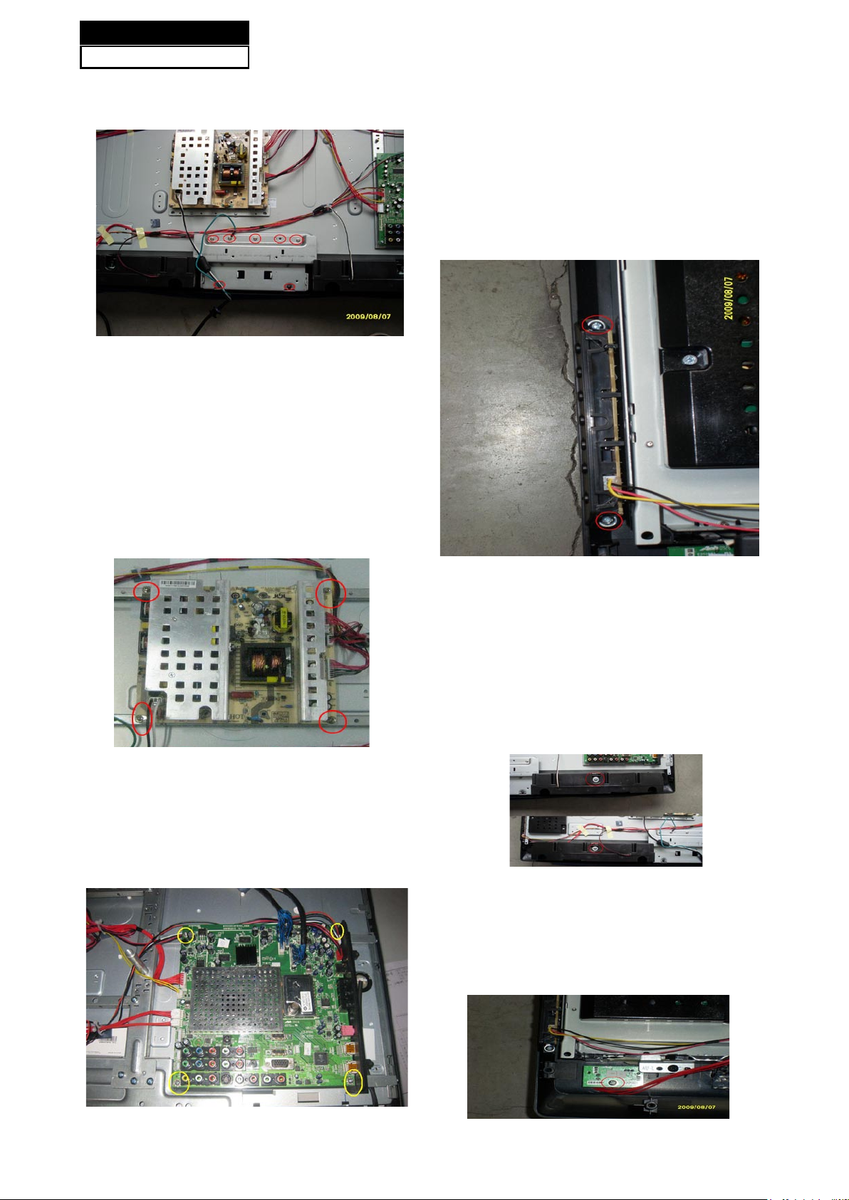
Then put the terminal bracket to the side.
3-5. Remove the Power Supply
Module
Remove the four screws indicated by the
red circles in below picture.
Then remove the power supply module.
3-6. Remove the Mainboard
Remove the eight screws indicated by the
rred circles in below picture.
3-7. Remove the Keypad Board
Disconnected th e coupler CN1 CN2 CN3
CN4 CN5 CN7 J25.
Remove the Mainboard.
3-8. Remove the Speaker
Remove the four screws indicated by the red
circles in below picture.
Take out the speakers.
3-9. Remove the Remote Control
Board
Remove the two screws indicated by the red
circles in below picture.
Take out the remote control board.
Service Manual
Model No.: HL42XZK42
12
Page 14
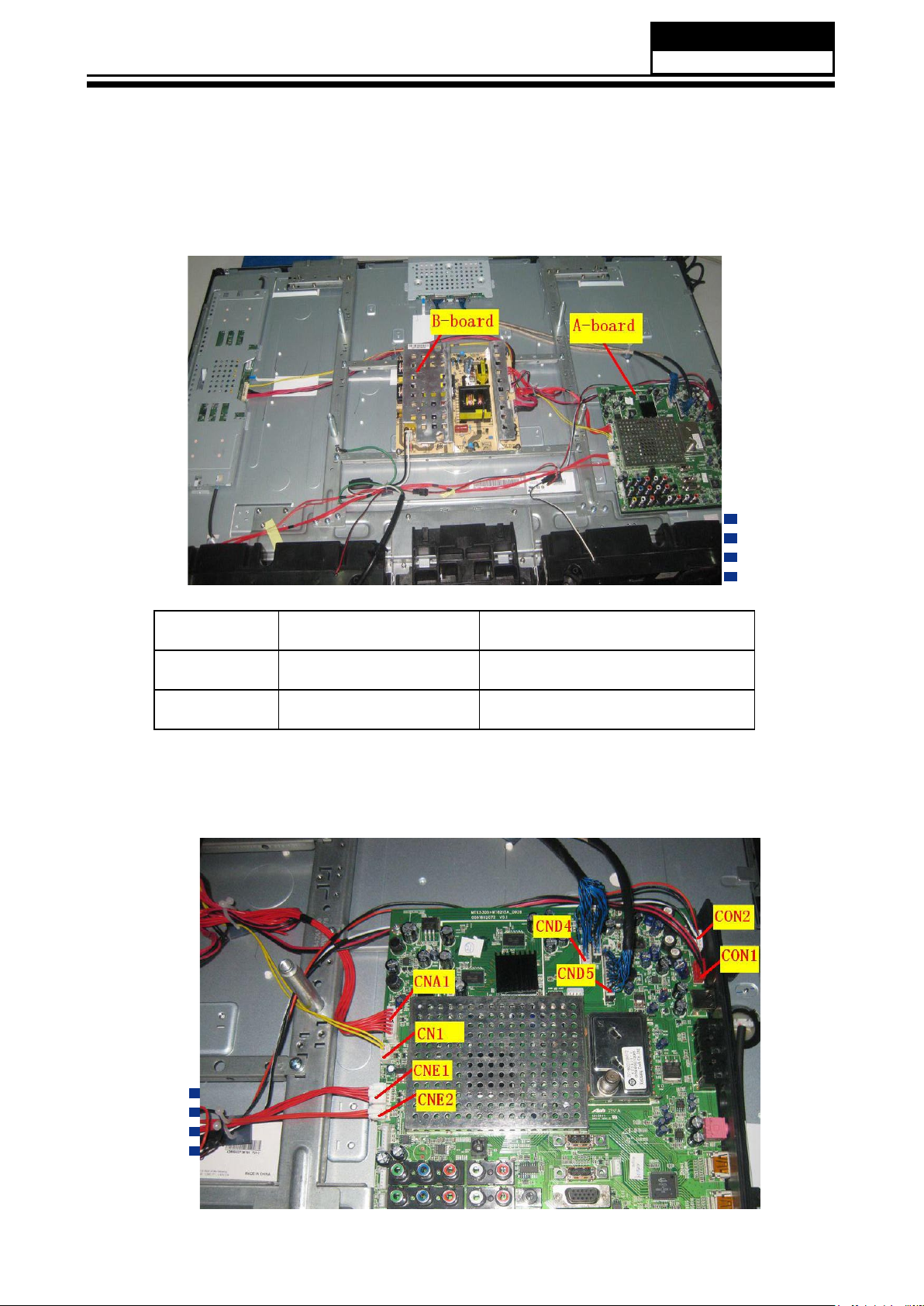
Chapter 4. Location of Controls and Components
4-1. Board Location
No. Parts number Description
A Board DC13U0E0200M Main Board(0090723952)
B Board 0094001176B Power Board
4-2. Main Board & AV Board
Service Manual
Model No.: HL42XZK42
13
Page 15
4-2-1 Function Description:
Main Board
Process signal which incept from exterior equipment then translate into signal that panel can display.
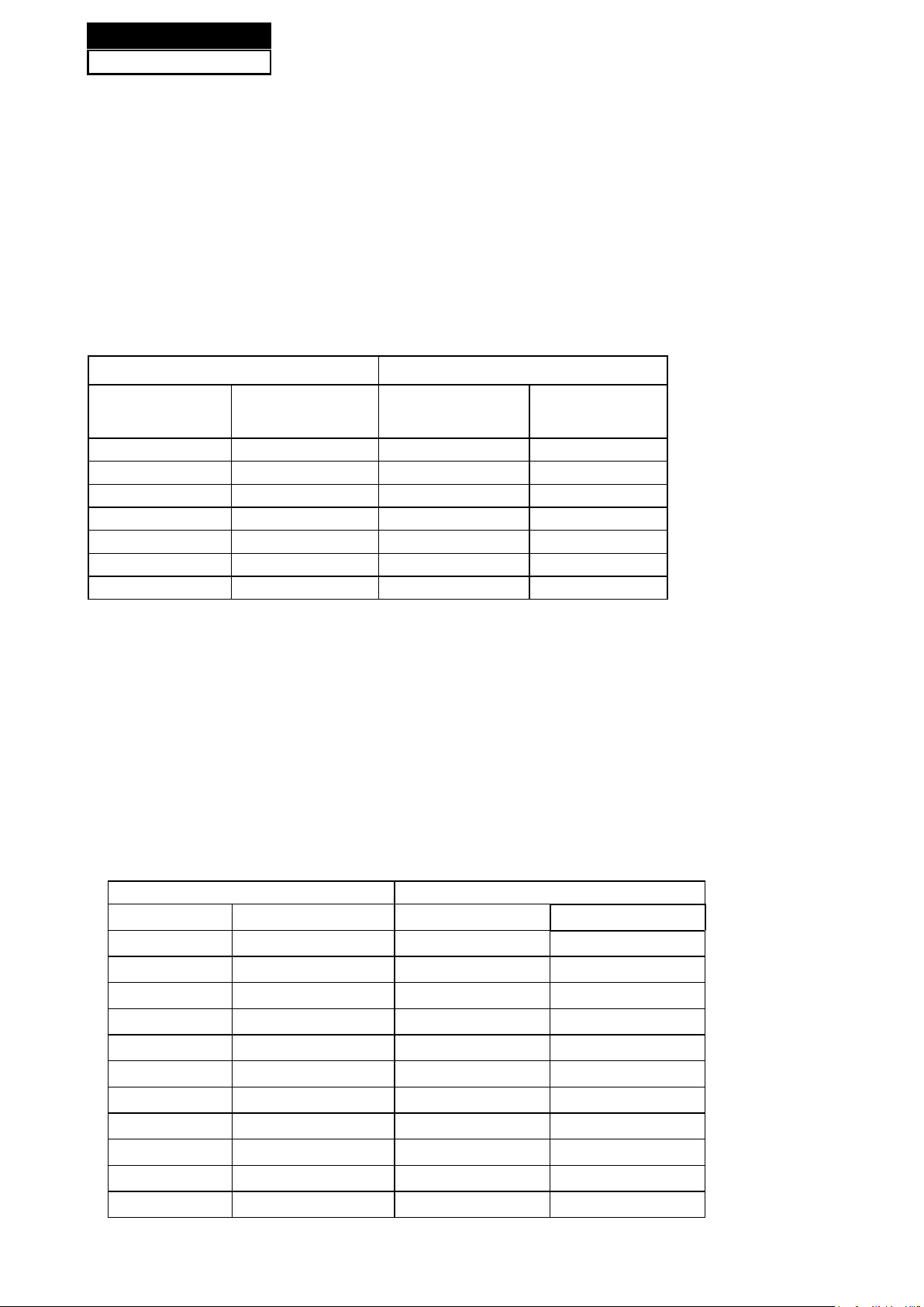
4-2-2 Connector denition
Main board connector
Power connectors (CN3, CN5)
CNA1 CN1
Pin number Signal name Pin number Signal name
1 +12V 1 DIMMING
2 +12V 2 ON/OFF
3 GND 3 GND
4 GND 4 SELECT
5 5VSB
6 GND
7 PSON
Notes:
CN1-Pin 2: Backlight on/off:
The system can turn on or turn off the backlight of TFT LCD Panel through the power supply
unit path.
CNA1-Pin 7: System power on / standby
System board will use this pin to control system power.
CN1-Pin 1: Control the luminance of backlight
The system can generate the PWN signal to control the strength of TFT LCD Panel’s
backlight through this connector
CNE1 CNE2
Pin number
Signal name Pin number
Signal name
1
SB5V 1
GND
2
IR 2
AD1
3
LED_R 3
AD2
4
LED_G
5
GND
Keypad and remote connector (CNE1,CNE2)
Service Manual
Model No.: HL42XZK42
14
Page 16
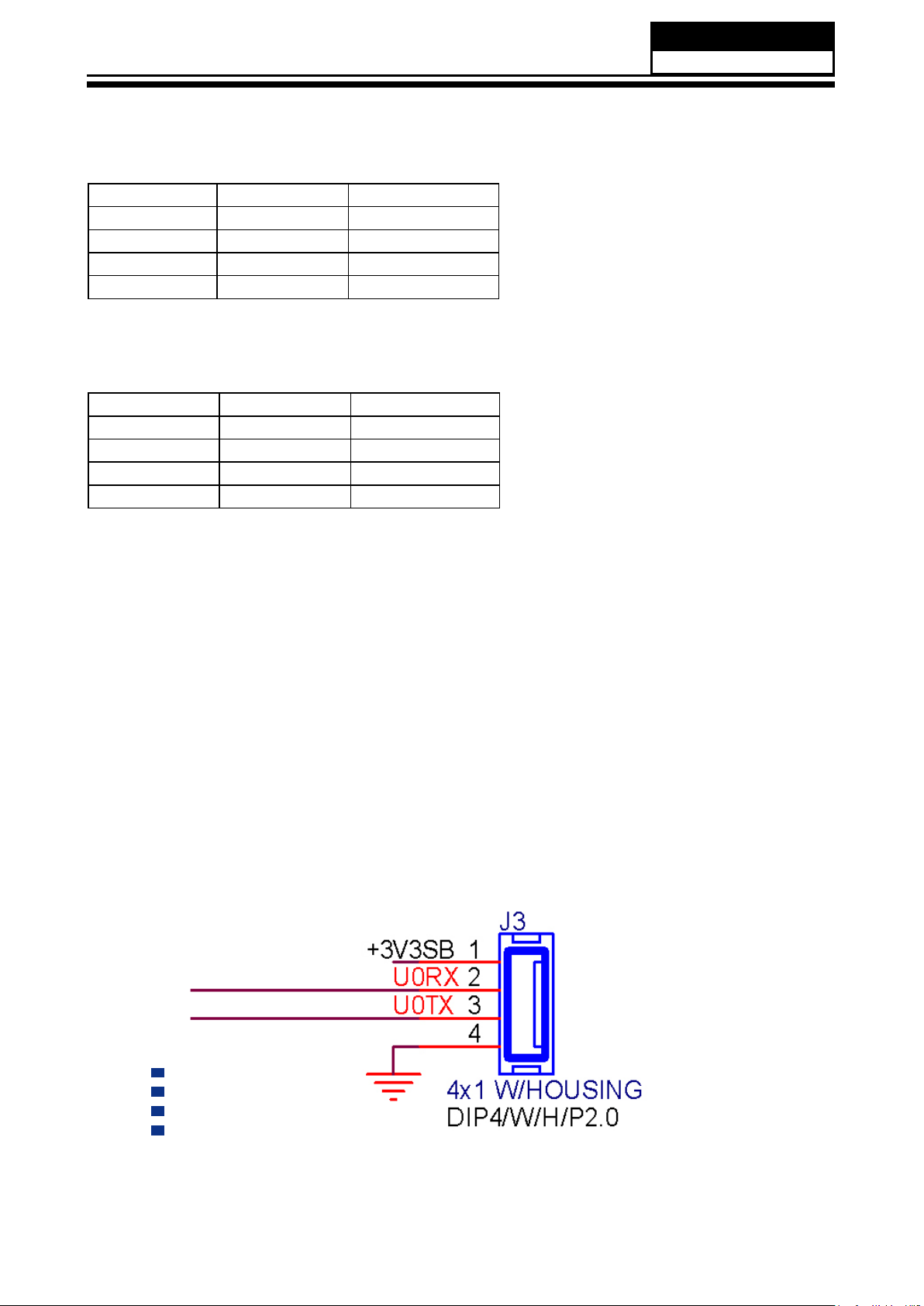
Speaker power connector (CON2)
Pin number Signal name
1 24V
2 24V
3 GND
4 GND
Speaker Connector (CON1)
Pin number Signal name
1 L+
2 L3 R4 R+
Other connectors:
CNB2 to Upgrade the program of MTK5380L (U13) AND FLASH (U17)
Service Manual
Model No.: HL42XZK42
15
Page 17
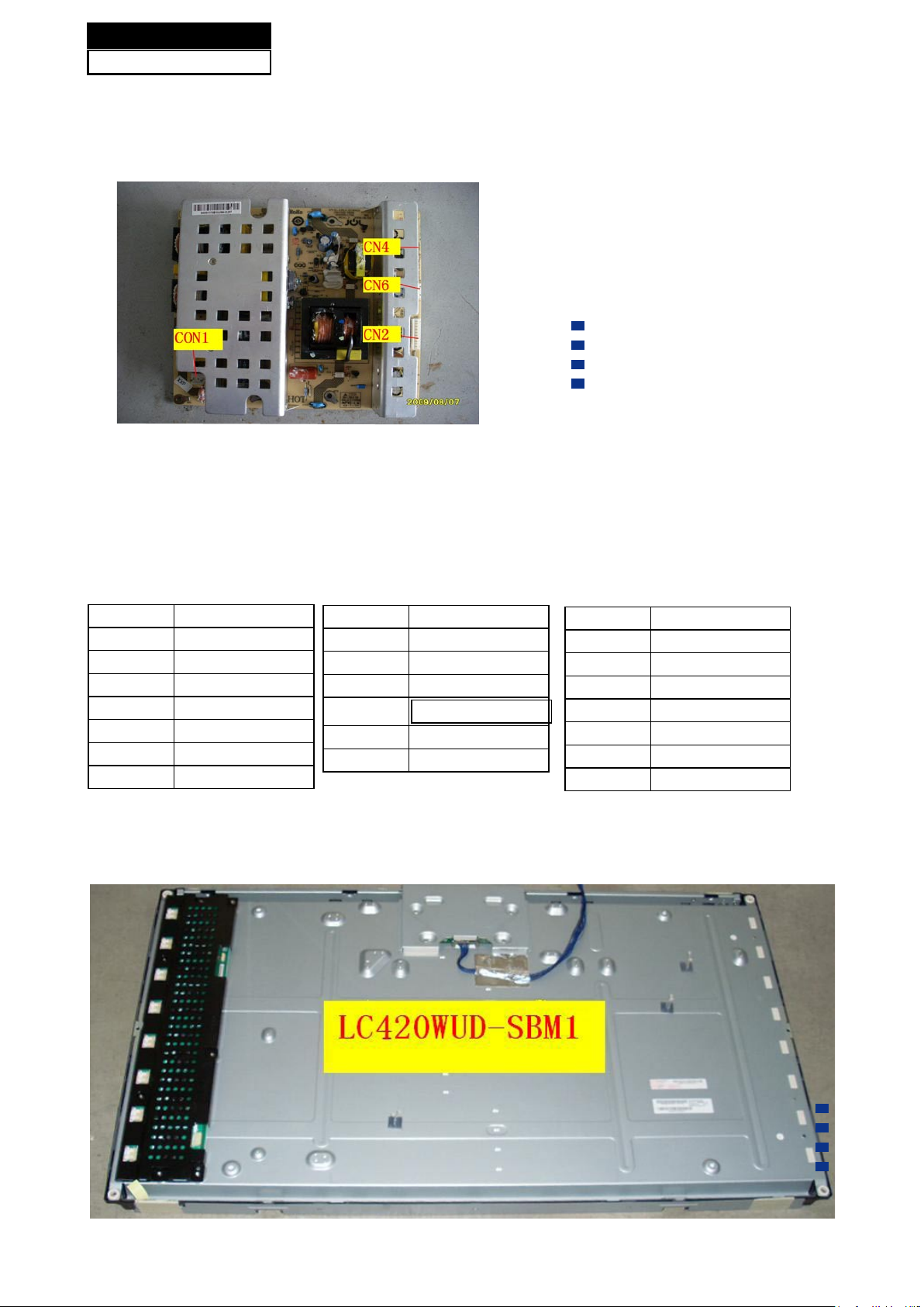
4-3. Power Supply Board
4-3-1. Function description:
To supply power for Mainboard, Panel.
4-3-2. Connector denition:
INPUT CONNECTOR (CN2)
CN2 Signal name
1 24V
~ 24V
5 24V
6 GND
~ GND
10 GND
4-4. LCD Panel
CN6 Signal name
1 24V
2 24V
3 GND
4
GND
CN4 Signal name
1 GND
2 GND
3 5VSB
4 GND
5 GND
6 +12V
7 +12V
Service Manual
Model No.: HL42XZK42
16
Page 18

Service Manual
Model No.: HL42XZK42
17
Page 19

Service Manual
Model No.: HL42XZK42
18
Page 20

Master
-Inverter Connector : 20022WR-14B1(Yeonho) or Equivalent
-Mating Connector : 20022HS-14or Equivalent
Service Manual
Model No.: HL42XZK42
19
Page 21
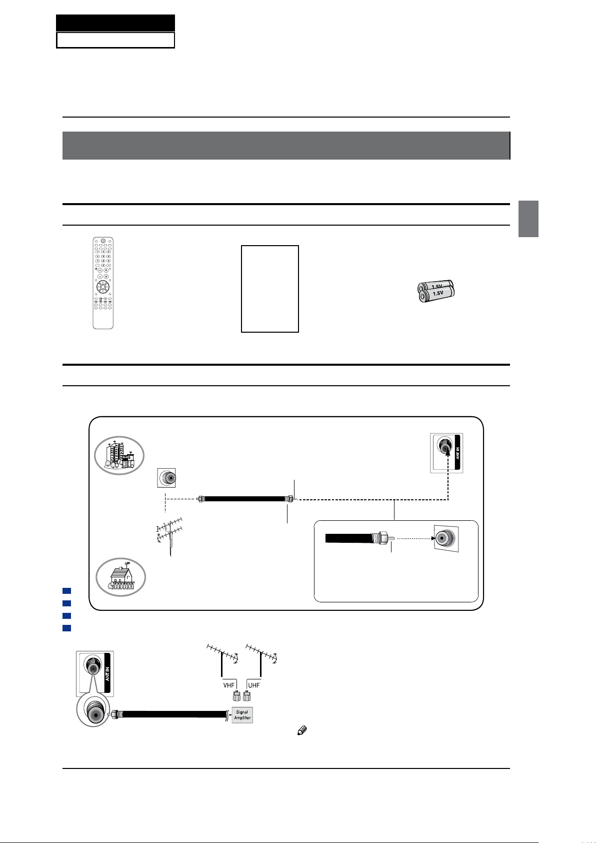
Installation
Haier LCD HDTV EN-8
Installation
External Equipment Connections
Accessories
Remote control Owner’s manual Alkaline battery (AAA) x2
Antenna Connection
Over-the-air TV reception quality will depend on your antenna type, antenna location and antenna positioning.
ANT IN
VHF Antenna
UHF Antenna
Turn clockwise to tighten
Bronze Wire
Be careful not to bend the bronze wire
when connecting the antenna.
Bronze Wire
Multi-family Dwellings/Apartments
(Connect to wall antenna socket)
Wall Antenna
Socket
RF Coaxial Wire (75 ohm)
Single-family Dwellings /Houses
(Connect to wall jack for outdoor antenna)
Outdoor Antenna
To improve the picture quality in a poor signal
area, please purchase a signal amplifier and install
properly.
If the antenna needs to be split for two TV’s, install a
“2-Way Signal Splitter” in the connections.
To install the antenna properly please contact a
professional in your area.
Note
All cables shown are not included with the TV.
3/$<3$86(
5(9
5(3($7
*8,'(
0766$3
&&' $5&
)5((=(
(17(5
6723 &(5%68
35(91(;7
&+/,67
)$925,7(
79
67%
,1387
087(
92/&+
0(18
<$/36,'3((/6
(;,7
5(&$//
3,&785($8',2 3& +'0,
&$%/(9&5 $8'
'9'
ANT IN
Chapter 5. Installation Instructions
5-1. External Equipment Connections
Service Manual
Model No.: HL42XZK42
20
Page 22
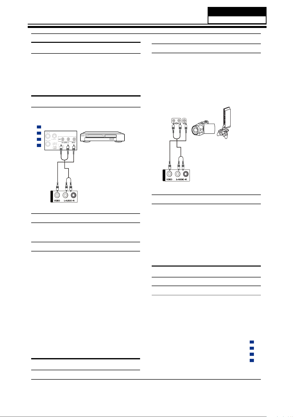
Installation
EN-9 Haier LCD HDTV
Choose Your Connection
There are several ways to connect your television,
depending on the components you want to connect
and the quality of the signal you want to achieve. The
following are examples of some different ways to
connect your TV with different input sources.
Connecting a VCR
To avoid picture noise (interference), leave an adequate
distance between the VCR and TV.
How to connect
Connect the audio and video cables from the •
external equipment’s output jacks to the TV input
jacks, as shown in the figure.
When connecting the TV to external equipment, •
match the jack colors (Video = yellow, Audio Left =
white, and Audio Right = red).
Camcorder or video
game set
Video= yellow
Audio left= white
Audio right= red
Back of TV
AV2 IN
How to use
Select the input source with using the
A
INPUT button
on the remote control.
Press
B
/
button to select the desired source.
Press
C
ENTER button to confirm.
Operate the corresponding external equipment.
D
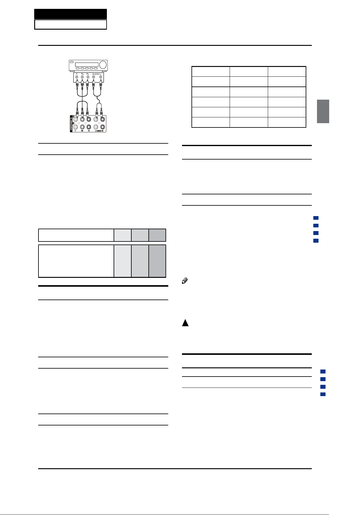
Component Setup
How to connect
Connect the DVD video outputs (COMPONENT) to the
Y Pb Pr jacks on the TV and connect the DVD audio
outputs to the YPbPr Audio IN jacks on the TV, as shown
in the figure.
Back of VCR
Back of TV
Video= yellow
Audio left= white
Audio right= red
AV2 IN
Connection Option 1
Set VCR output switch to channel 3 or 4 and then turn
the TV to the same channel number.
Connection Option 2
Connect the audio and video cables from the VCR’s
A
output jacks to the TV input jacks, as shown in the
figure. When connecting the TV to VCR, match the
jack colors (Video = yellow, Audio Left = white, and
Audio Right = red). If you connect a S-VIDEO output
from VCR to the S-VIDEO input, the picture quality is
improved; compared to connecting a regular VCR to
the Video input.
Insert a video tape into the VCR and press
B
PLAY on
the VCR. (Refer to the VCR owner’s manual.)
Select the input source with using the
C
INPUT button
on the remote control, and then press
/
button
to select the source, press ENTER button to confirm.
External A V Source Setup
Service Manual
Model No.: HL42XZK42
21
Page 23
Installation
Haier LCD HDTV EN-10
Component video device
Component video cable:
Green=Y
Blue=CB/PB
Red=CR/PR
Audio cable:
White=Left audio
Red=Right audio
Back of TV
How to use
Turn on the DVD player, insert a DVD disc.
A
Use
B
INPUT button on the remote control to select
component mode.
Component Input ports
To get better picture quality, connect a DVD player to
the component input ports as shown below.
Component ports on the TV Y Pb Pr
Video output ports on DVD
player
Y
Y
Y
Y
Pb
B-Y
Cb
P
B
Pr
R-Y
Cr
P
R
Connecting a DTV (digital TV)
This TV can receive Digital Over-the-air/Cable signals
without an external digital set-top box. However, if you do
receive Digital signals from a digital set-top box or other
digital external device, refer to the figure as shown below.
This TV supports HDCP (High-bandwidth Digital Contents
Protection) protocol for Digital Contents (480 p,720 p,1080 i).
How to connect
Use the TV’s COMPONENT, VGA or HDMI jack for •
video connections, depending on your set-top box
connector. Then, make the corresponding audio
connections.
How to use
Turn on the digital set-top box. (Refer to the owner’s
A
manual for the digital set-top box.)
Use INPUT on the remote control to select
B
COMPONENT, VGA or HDMI source.
Signal COMPONENT HDMI
480 i Ye s Ye s
480 p Ye s Ye s
720 p Ye s Ye s
1080 i Ye s Ye s
1080 p Yes Ye s
Connecting a digital audio output
Send the TV’s audio to external audio equipment (stereo
system) via the Digital Audio Output (Optical) port.
How to connect
Connect one end of an optical cable to the TV Digital
A
Audio (Optical) Output port.
Connect the other end of the optical cable to the
B
digital audio (optical) input on the audio equipment.
See the external audio equipment instruction
manual for operation.
Note
When connecting with external audio equipments,
such as amplifers or speakers, please turn the TV
speakers off.
!
Caution:
Do not look into the optical output port. Looking •
at the laser beam may damage your vision.
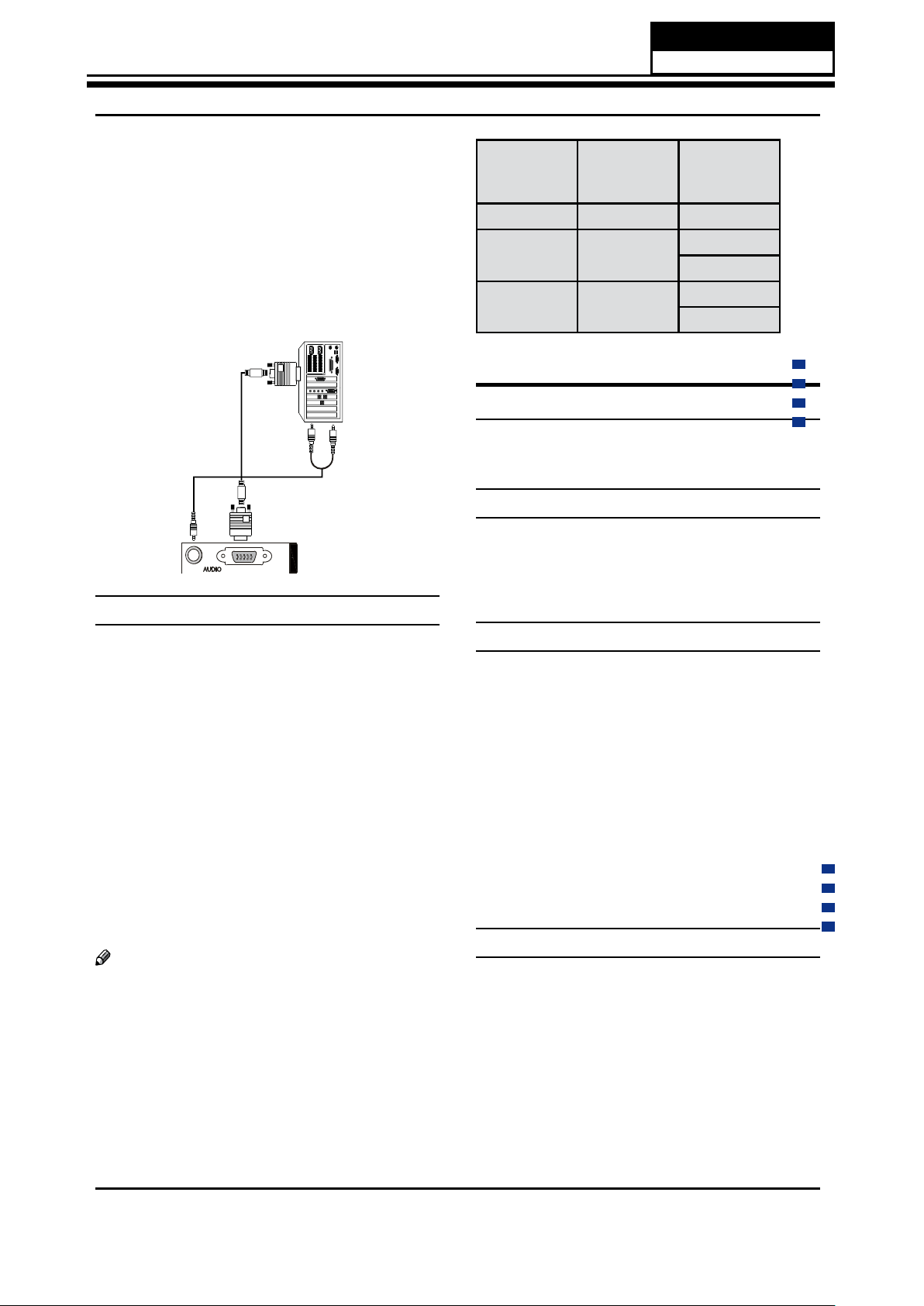
Connecting a computer
How to connect
To get the best picture quality, adjust the VGA
A
graphics card to 1024s 768.
Use the TV’s VGA or DVI (Digital Visual Interface)
B
Audio IN port for audio connections, depending on
your computer connector.
If the graphic card on the computer does not •
output analog and digital RGB simultaneously,
Service Manual
Model No.: HL42XZK42
22
Page 24
Installation
EN-11 Haier LCD HDTV
connect only one of either VGA IN or HDMI IN to
display the VGA on the TV.
If the graphic card on the computer does output •
analog and digital RGB simultaneously, set the TV
to either VGA or HDMI; (the other mode is set to
Plug and Play automatically by the TV.)
Then, make the corresponding audio connection.
C
If using a sound card, adjust the VGA sound as
required.
PC/DVI
PC
PC IN
How to use
Turn on the computer and the TV.
A
Use INPUT on the remote control to select VGA or
B
HDMI source.
Check the image on your TV. There may be noise
C
associated with the resolution, vertical pattern,
contrast or brightness in VGA mode. If noise
is present, change the VGA mode to another
resolution, change the refresh rate to another rate
or adjust the brightness and contrast on the menu
until the picture is clear. If the refresh rate of the VGA
graphic card can not be changed, change the VGA
graphic card or consult the manufacturer of the VGA
graphic card.
Note
Use a DVI cable.
Avoid keeping a fixed image on the TV’s screen
for a long period of time. The fixed image may
become permanently imprinted on the screen.
The synchronization input form for Horizontal and
Vertical frequencies is separate.
Resolution
Mode Resolution
Frame
frequency
(Hz)
VGA
640s480
60 Hz
SVGA
800s600
60 Hz
75 Hz
XGA
1024s768
60 Hz
75 Hz
5-2. HDMI Connections
HDMI and DVI input
When the source device (DVD player or Set Top Box)
supports HDMI
How To Connect
Connect the source device to HDMI port of this TV
A
with an HDMI cable (not supplied with this product).
No separated audio connection is necessary.
B
How To Use
If the source device supports Auto HDMI function, •
the output resolution of the source device will be
automatically set to 1280s720 p.
If the source device does not support Auto HDMI, •
you need to set the output resolution appropriately.
To get the best picture quality, adjust the output
resolution of the source device to 1280s720 p.
Select HDMI input source in input source option of •
Select Main source menu.
When the source device (DVD player or Set Top Box)
supports DVI
How To Connect
Connect the source device to HDMI port of this TV
A
with a HDMI-to-DVI cable (not supplied with this
product).
A separated audio connection is necessary.
B
C
If the source device has an analog audio output
connector, connect the source device audio output to
DVI Audio In port located on the left side of HDMI port.
Service Manual
Model No.: HL42XZK42
23
Page 25
Installation
Haier LCD HDTV EN-12
If the source device supports Auto DVI function, •
the output resolution of the source device will be
automatically set to 1280s720 p.
If the source device does not support Auto DVI, you •
need to set the output resolution appropriately.
To get the best picture quality, adjust the output
resolution of the source device to 1280s720 p.
Press the • INPUT button to select HDMI input source
in input source option of Select Main source menu.
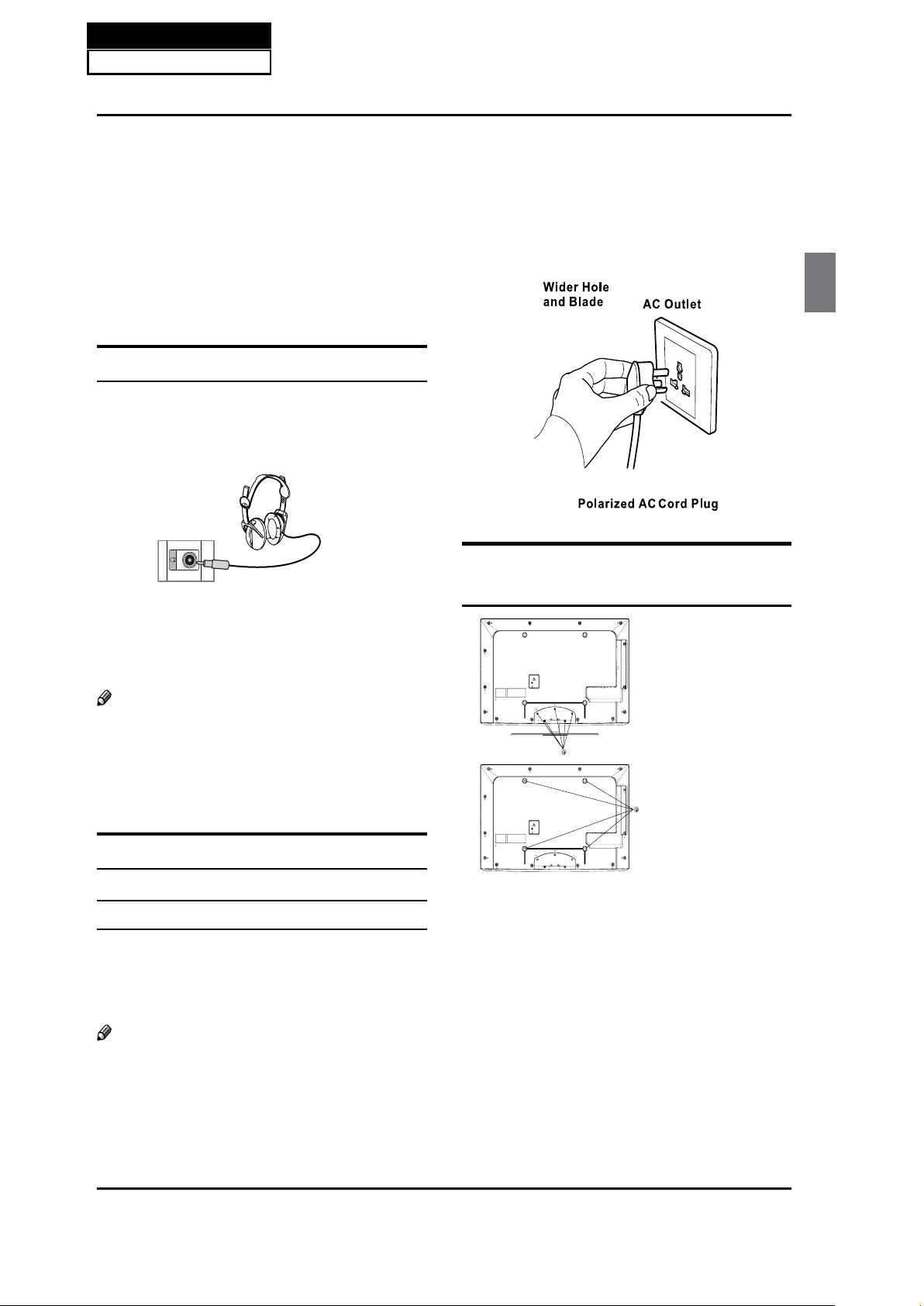
Connecting Headphones
You can connect a set of headphones to your set
if you wish to watch a TV programme without
disturbing the other people in the room.
Back of TV
Plug a set of headphones into the 3.5 mm mini-jack
socket on the side panel of the set.
Note
Prolonged use of headphones at a high volume
may damage your hearing.
You will not receive sound from the speakers when
you connect headphones to the system.
Power source
TO USE AC POWER SOURCE
Use the AC polarized line cord provided for •
operation on AC. Insert the AC cord plug into a
standard polarized AC outlet.
Note
Never connect the AC line cord plug to other than
the specified voltage. Use the attached power cord
only.
If the polarized AC cord does not fit into a non-
polarized AC outlet, do not attempt to file or cut
the blade. It is the user’s responsibility to have an
electrician replace the obsolete outlet.
If you cause a static discharge when touching the
unit and the unit fails to function, simply unplug
the unit from the AC outlet and plug it back in. The
unit should return to normal operation.
Removing the table stand and
installing a wall mount bracket
Remove 5 s M4 screws
securing the stand to
the TV, then remove
the stand.
Use 4 s M8 screws
to secure the wall
bracket (not supplied)
to the back of your TV.
Service Manual
Model No.: HL42XZK42
24
Page 26
Introduction
EN-5 Haier LCD HDTV
Introduction
Controls
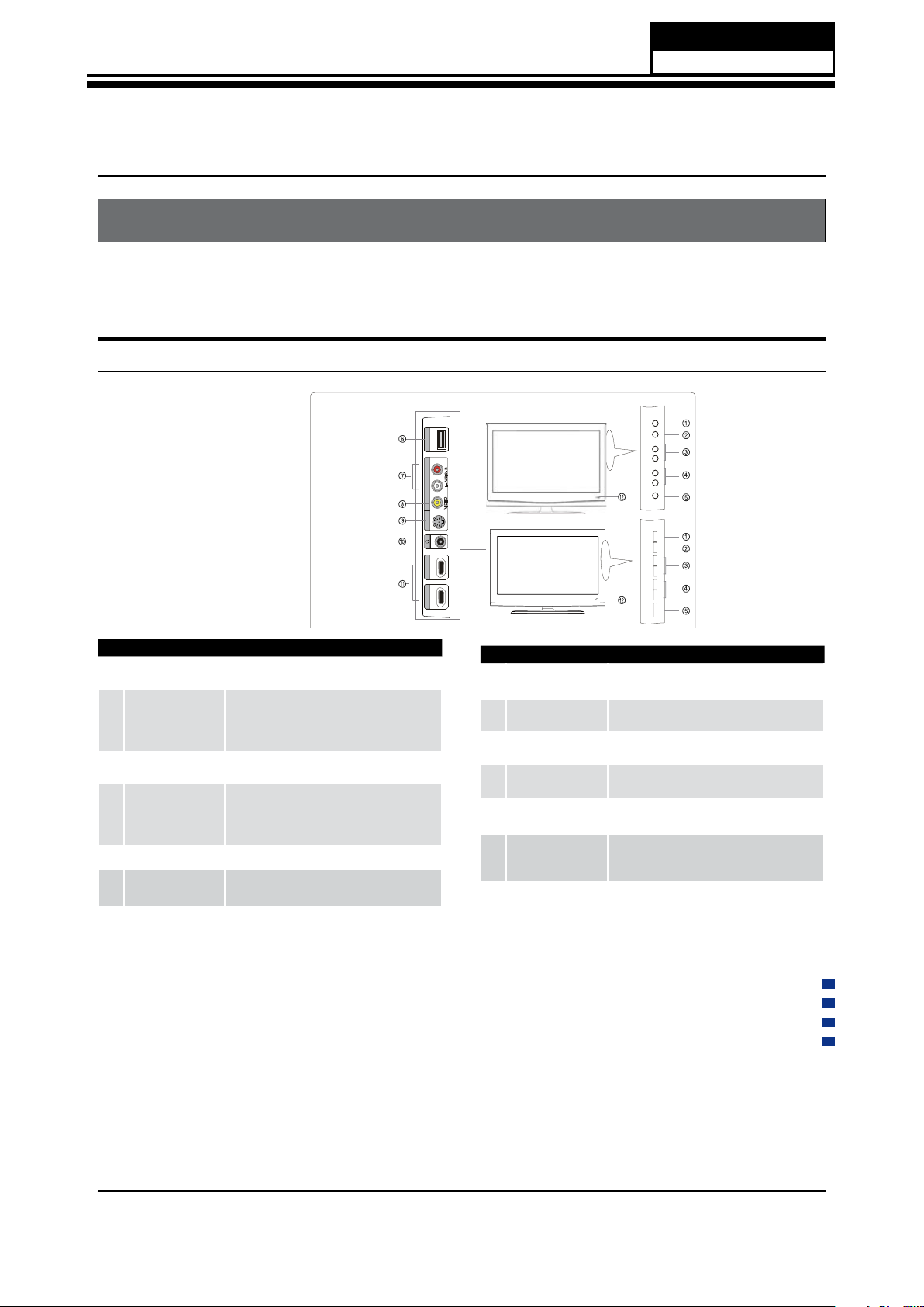
This is a simplified representation of the TV front panel, side panel control buttons and side inputs.
TV Side panel controls and connections
R3 series
K3 series
L- AUDIO - R
HDMI1 INHDMI2 IN USB
AV 1 IN
S-VIDEO
VIDEO
MEN
UI
N
PU
T VO
L
+ VO
L
- C
H
+ CH
- PO
WERMENUI
NPU
T VO
L
+ VO
L
- CH
+ C
H
- PO
W
ER
1
MENU
Menu display. Press to access the on-screen
menu display.
2
INPUT
Press to access the input source mode. Press
repeatedly to change the source to the one
you want to watch. In the MENU screen, the
INPUT button serves as the ENTER button.
3
VOL +/-
Press to adjust the volume. In the MENU screen,
these buttons serve as left/right buttons.
4
CH +/-
Press to scan through channels. To scan quickly
through channels, press and hold down either
+/- . In the MENU screen, these buttons serve
as up/down buttons.
5
POWER Press to turn on and off the TV.
6
USB input
Connect a USB ash drive to view MPEG2 videos,
JPEG images or listen to MP3 songs
.
7
Av2 AUDIO IN
Connect the audio L/R cables from the video
signal source to these jacks.
8
AV2 VIDEO IN
Connects the composite video cable from an
external signal source to this jack.
9
S-VIDEO
Connects the S-VIDEO cables from an external
signal source to this jack.
0
Headphone
jack
Headphone audio output terminal.
A
HDMI In
Connect a HDMI device to receive digital audio
and uncompressed digital video.
B
Remote Sensor
Receivers IR signals from the remote control.
Do not put anything near the sensor, which
may block the remote control signal.
Chapter 6. Operation Instructions
6-1. Front Panel Controls
Service Manual
Model No.: HL42XZK42
25
Page 27
Introduction
Haier LCD HDTV EN-6
Connection Options
Back panel connections
PC/DVI
PC
PC IN
3
4
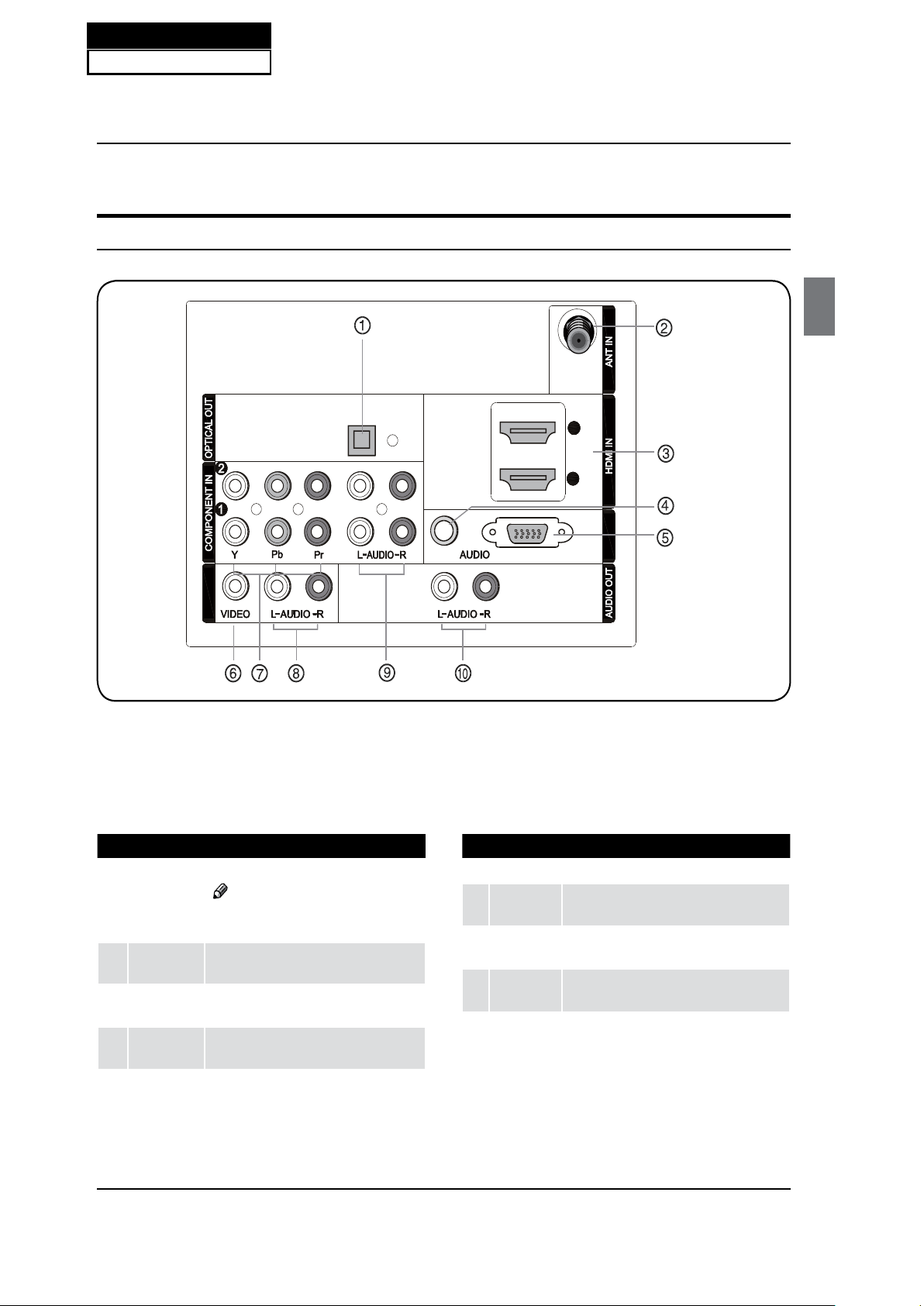
AV2 IN
1
Digital Audio
Output
Connect various types of digital audio equipment.
Note
In standby mode, these ports will not
work.
2
Antenna
Input
Connect cable or antenna signals to the TV,
either directly or through your cable box.
3
HDMI In
Connect a HDMI device to receive digital audio
and uncompressed digital video.
4
PC Audio In
Connect the audio L/R cables from a computer
to this jack.
5
PC Video In
Connect a video cable from a computer to this
jack.
6
VIDEO In
Connects the video signal from a video device.
7
Component
Video In
Connect a component video device to these jacks.
8
AUDIO In
Connect the audio L/R cables from the video signal
source to these jacks.
9
COMPONENT
AUDIO In
Connect the audio L/R cables from the component
video signal source to these jacks.
0
AUDIO Out
Connect the audio L/R cables to your audio equipment.
Service Manual
Model No.: HL42XZK42
26
6-2. Back Panel Controls
Page 28
Introduction
EN-7 Haier LCD HDTV
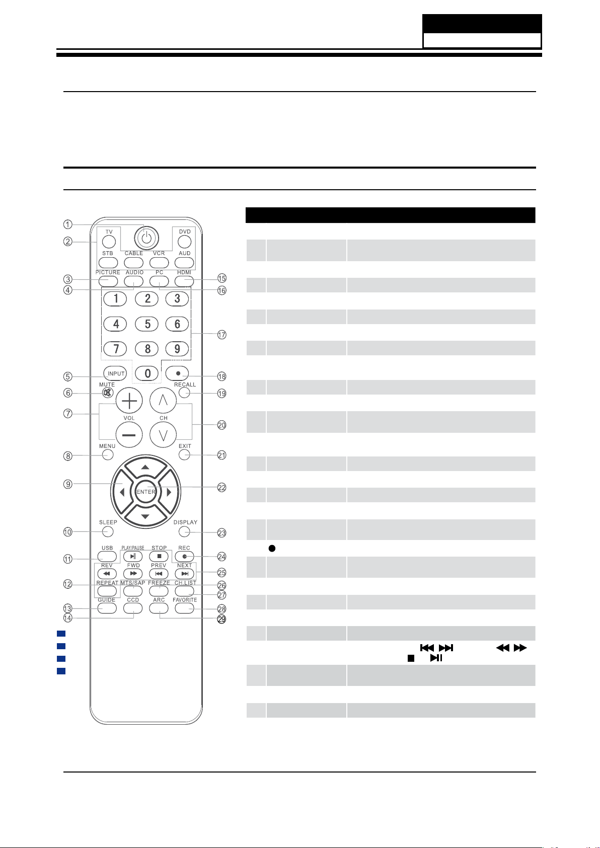
Universal Remote control
The remote control cannot be operated unless the batteries are properly loaded.
When using the remote control, aim it at the remote sensor on the TV.
1
POWER Press to turn on and off the TV.
2
TV DVD SETBOX CABLE
VCR AUD
To select one of the system modes in which the remote control
can be used.
3
PICTURE Press repeatedly to cycle through the available picture modes.
4
AUDIO Press to cycle through different sound settings.
5
INPUT Show the input source.
6
MUTE Switches the video sound on or off.
7
VOLUME UP/DOWN Press to adjust the volume.
8
MENU Press to open the on-screen menu.
9
THUMBSTICK (Up/
Down/Left/Right)
Allows you to navigate the on-screen menus and adjust the
system settings to your preference.
0
SLEEP button Press to display the sleep timer option.
A
USB Press to switch input source to USB in.
B
MTS/SAP
Selects MTS sound: Mono, Stereo, and SAP in Analog mode.
Change the audio language in DTV mode.
C
GUIDE
Press to display the guide when you are watching analog or
digital channels.
D
CCD(closed caption) Select a closed caption.
E
HDMI Press to select a device connected to the HDMI input
F
PC Press to select the computer connected to the VGA input
G
Number buttons Press to change a channel.
H
tCVUUPO
Press to select digital channels. For example, to enter “54-3” ,
QSFTTiwitwBOEiw
I
RECALL Press to jump back and forth between two channels.
J
CHANNEL UP/DOWN
Press to scan through channels. To scan quickly between the
last two channels, press and hold down either +/-.
K
EXIT
Clears all on-screen displays and returns to TV viewing from any menu.
L
ENTER Accesses the highlighted item in the on-screen menu.
M
DISPLAY
Press to display the TV status information on the top of the TV screen.
N
REC Press to start the recording process
O
USB Functions
Control the USB System.
/ Rewind / Fast /
Backward /Forward Stop Play/Pause REPEAT
P
FREEZE
Press once to display a frozen image of the current program,
but audio continues. Press again to return to the program.
Q
CH.LIST Open the channel list in TV.
R
FAV.LIST Press to open the favorite channel list in TV.
S
ARC(Aspect Ratio Control)
Press to change the aspect ratio.
Function introduction
6-3. Setting Up Your Remote Control
Service Manual
Model No.: HL42XZK42
27
Page 29
Service Manual
Model No.: HL42XZK42
28
Chapter 7. Electrical Parts
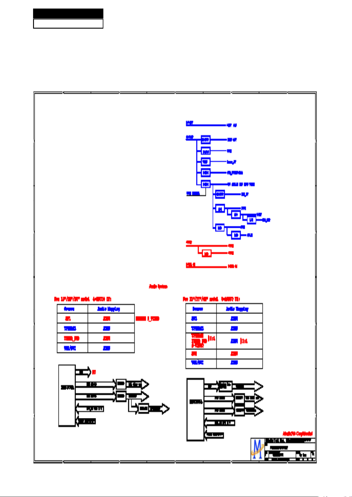
7-1. Block Diagram
Page 30
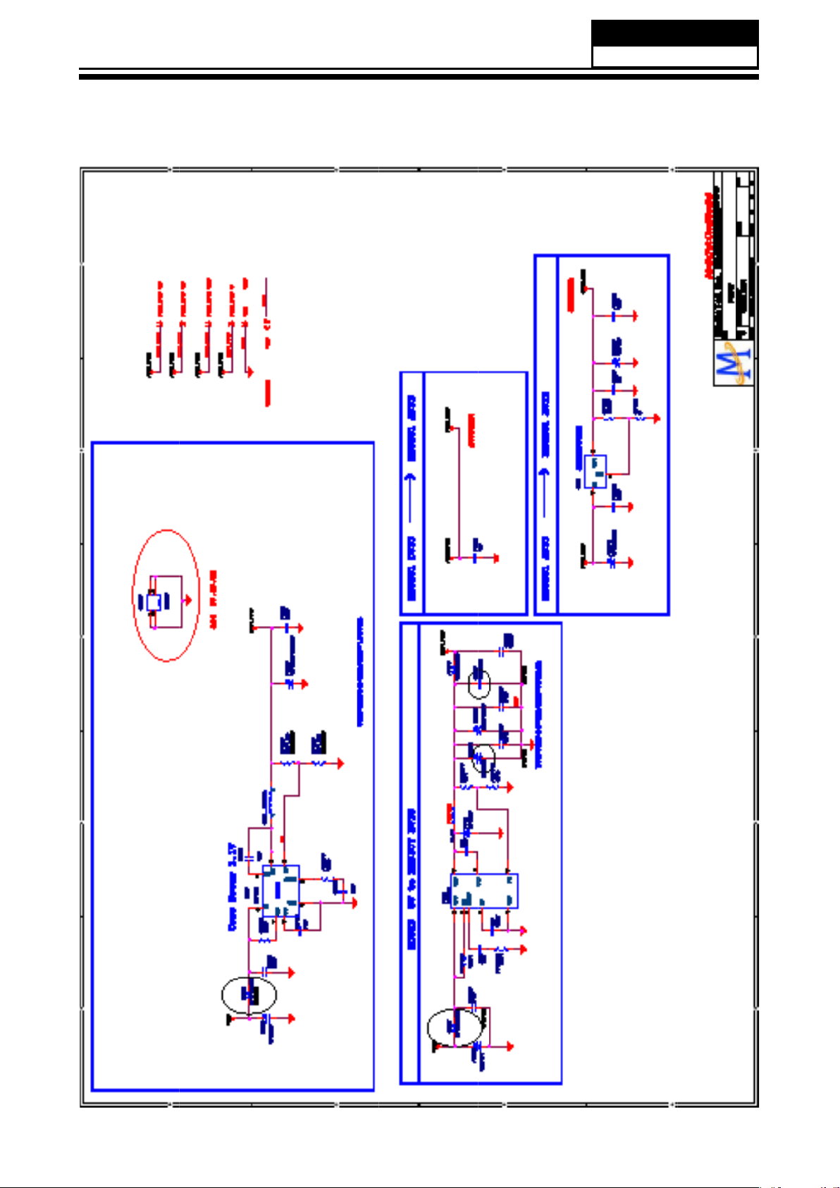
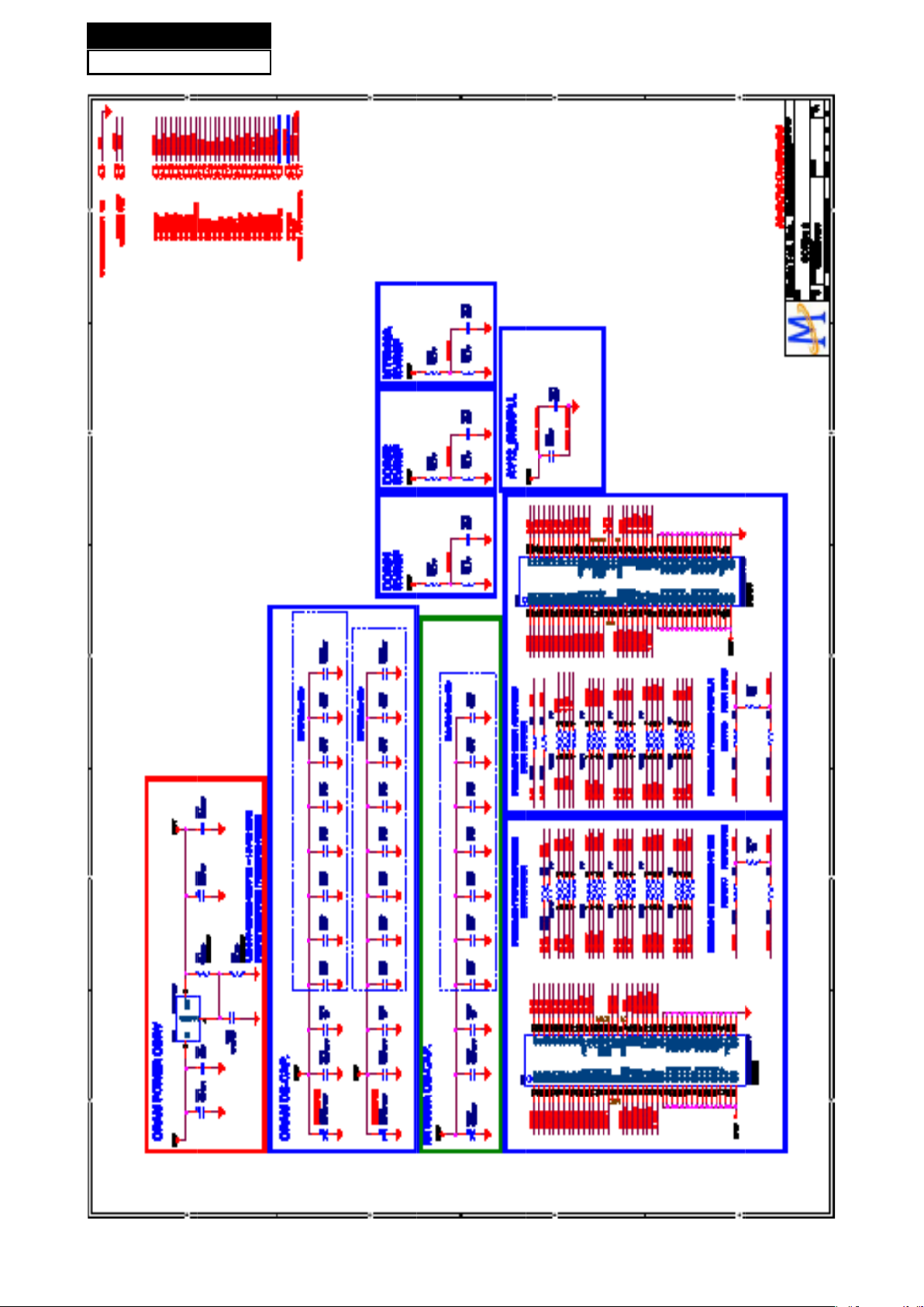
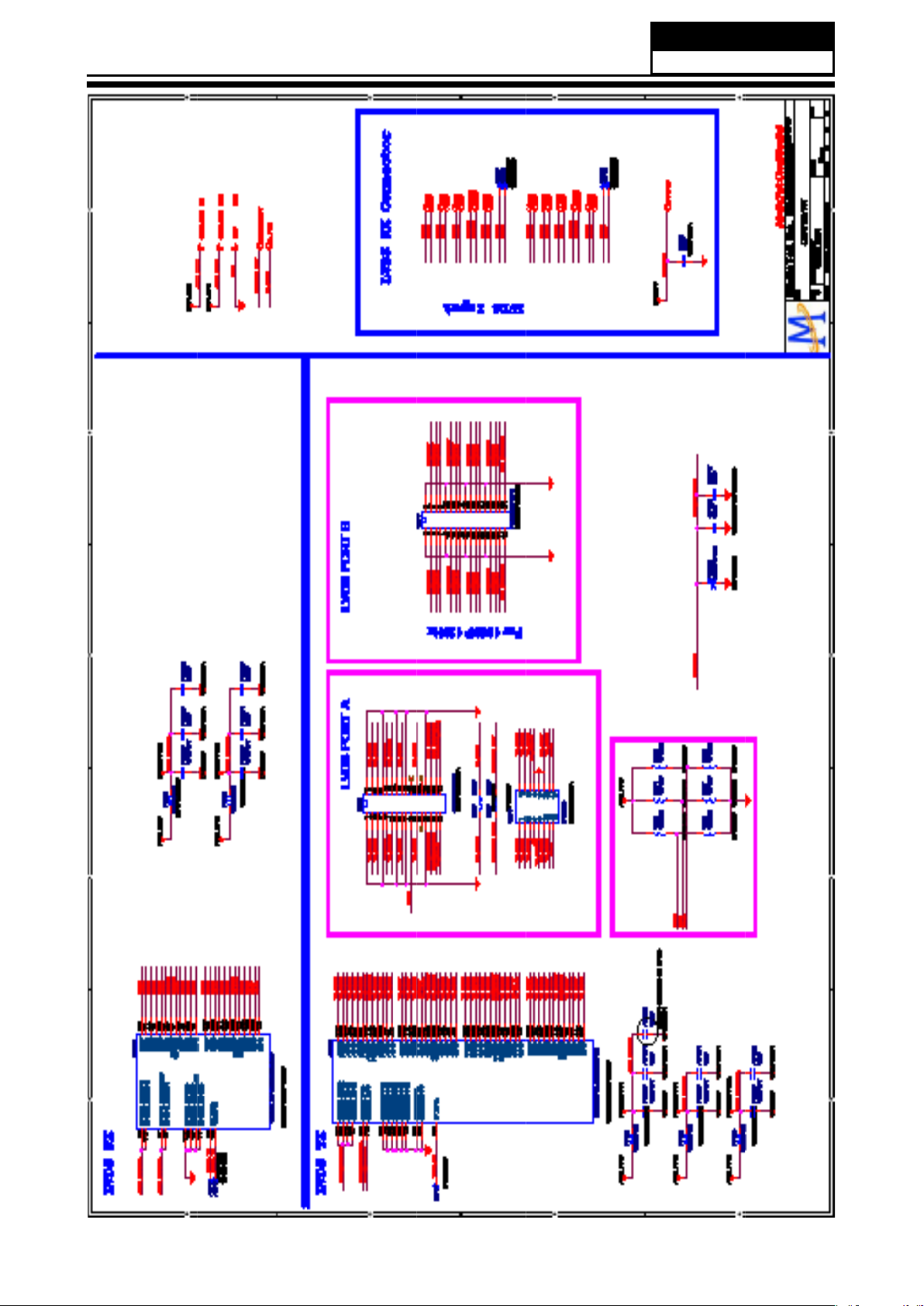
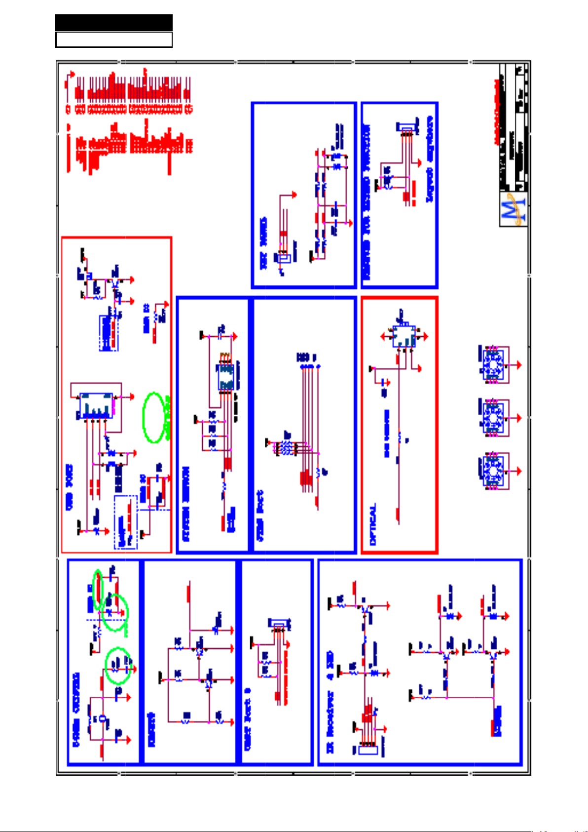
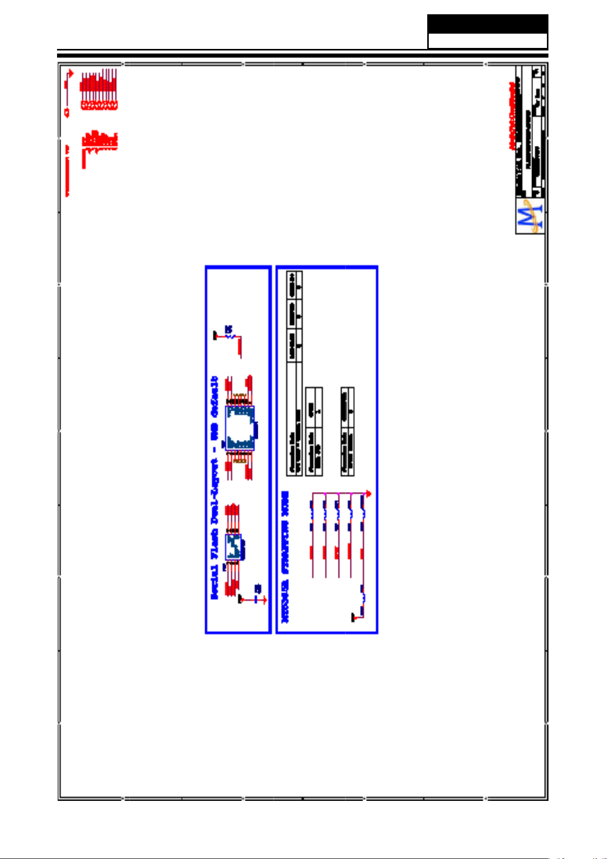
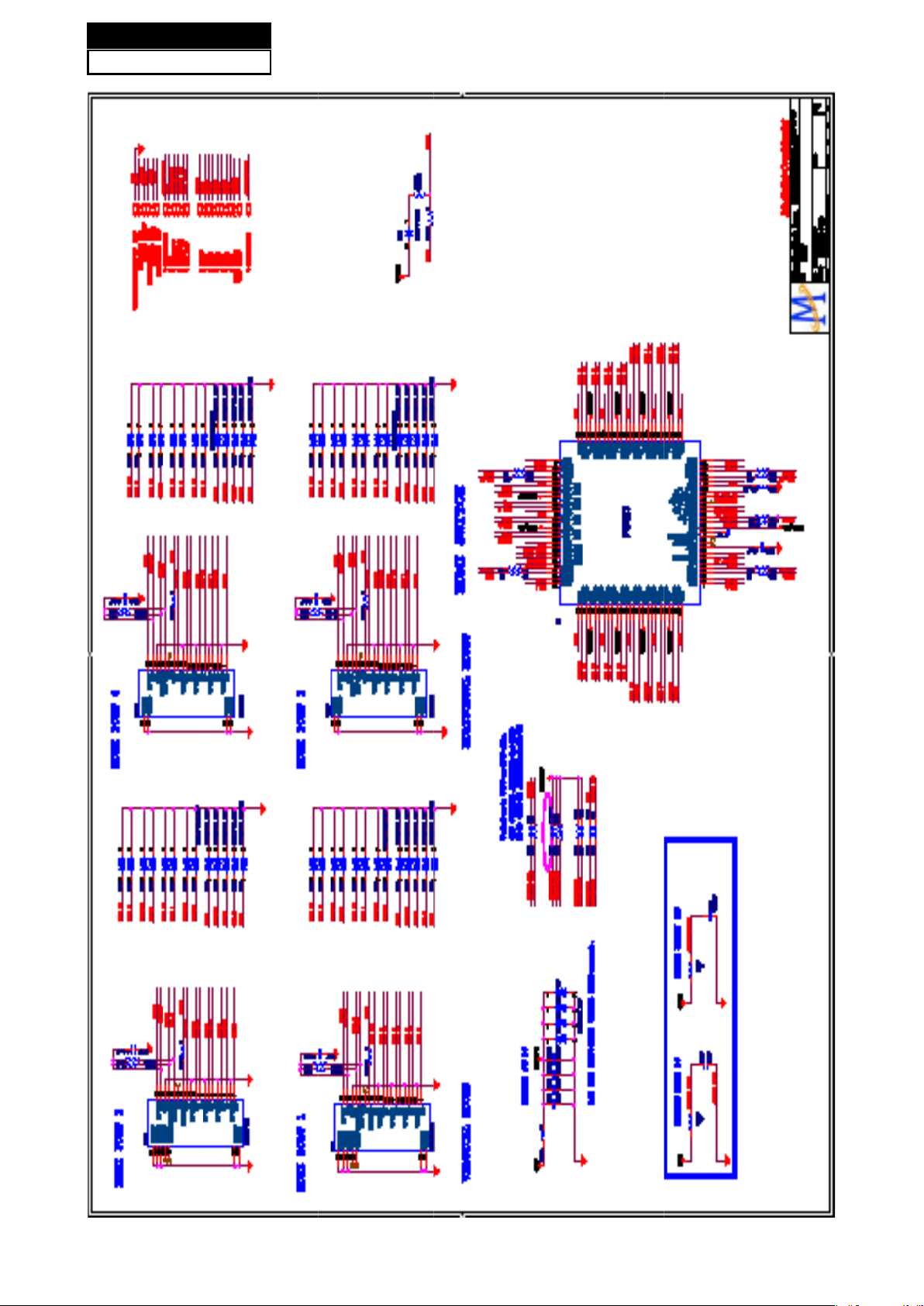
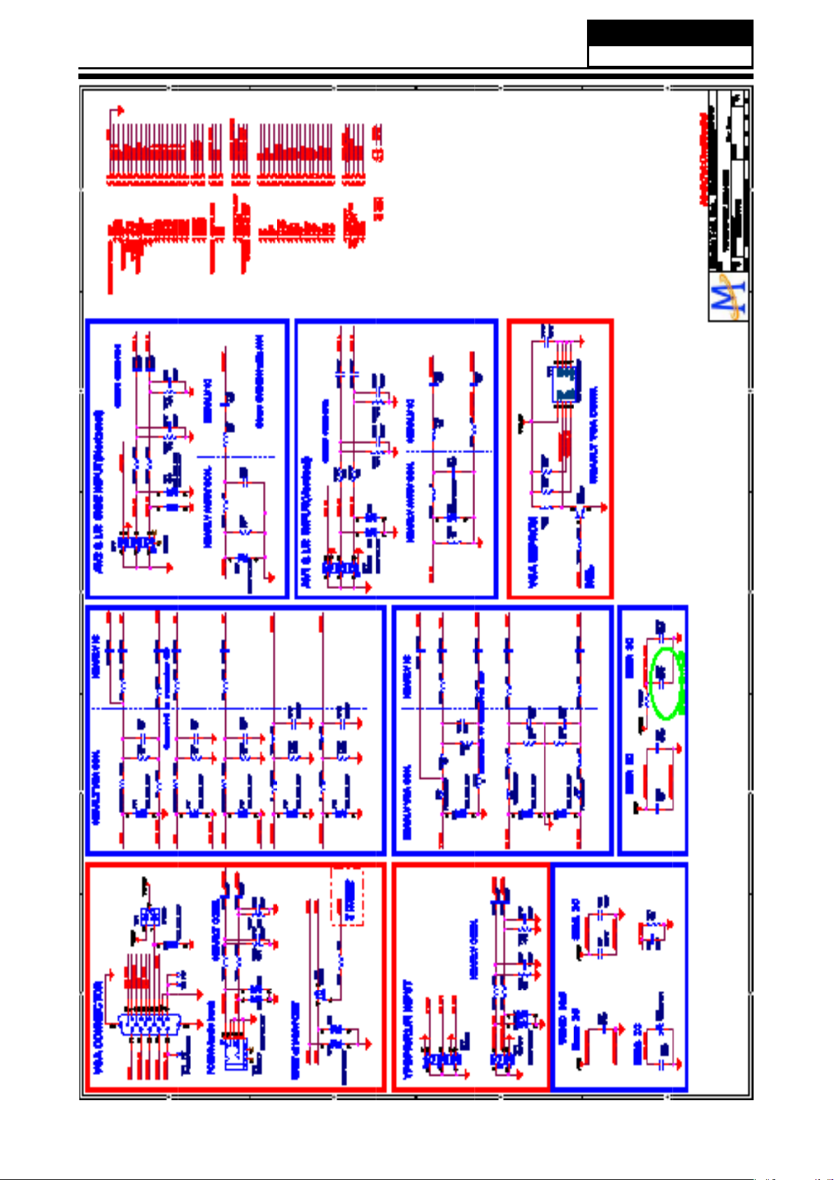
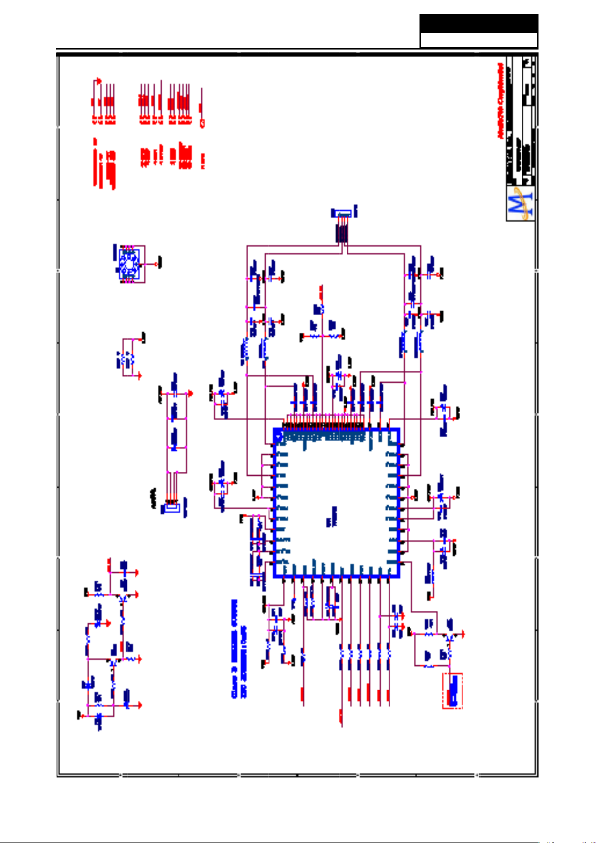
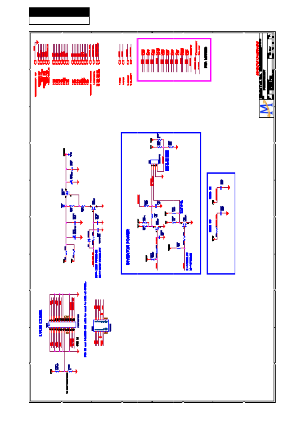
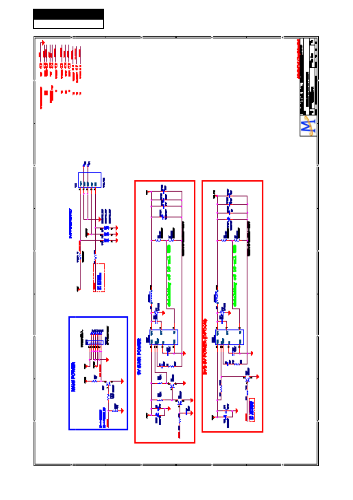
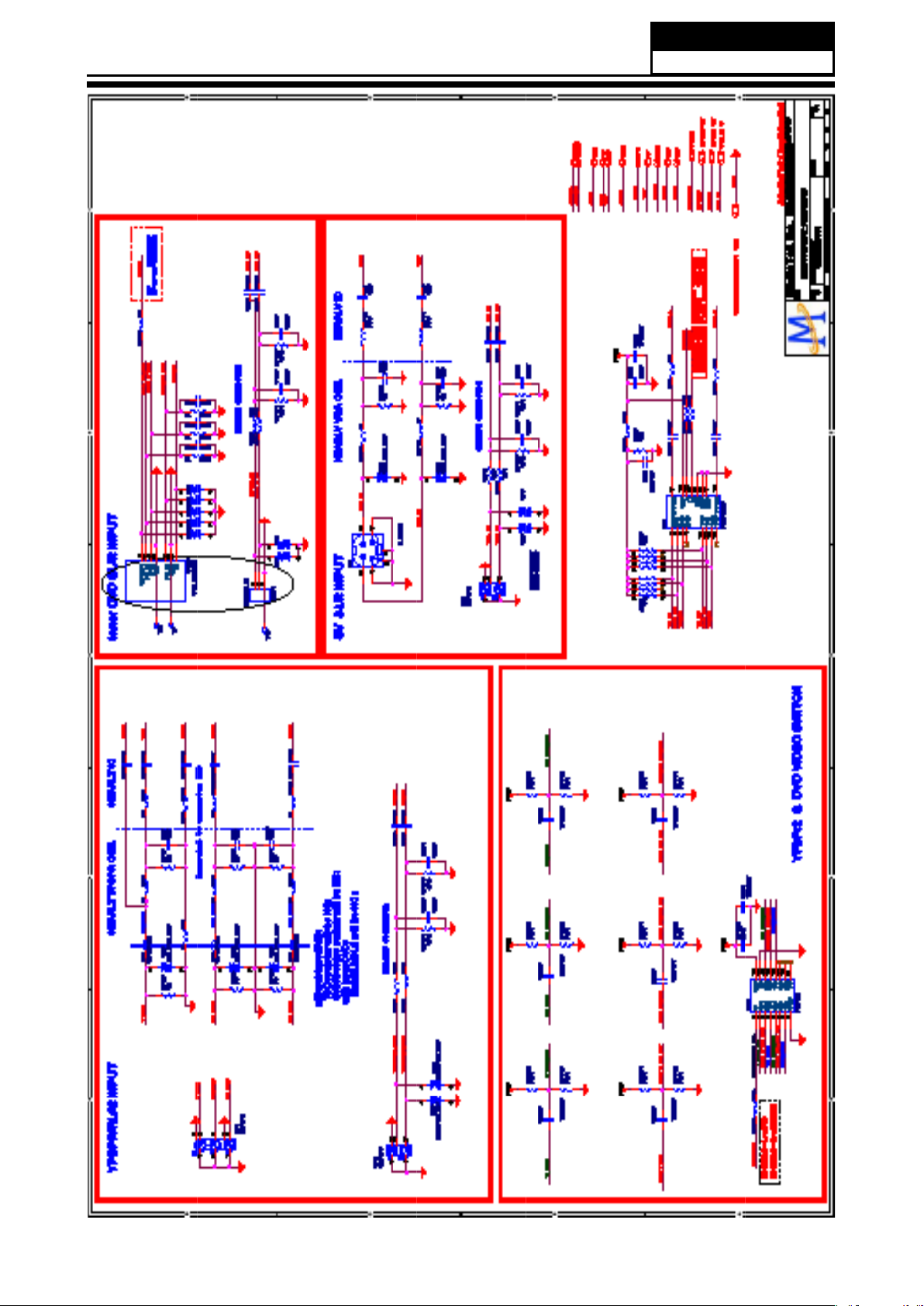
7-2. Circuit Diagram
Service Manual
Model No.: HL42XZK42
29
Page 31
Service Manual
Model No.: HL42XZK42
30
Page 32
Service Manual
Model No.: HL42XZK42
31
Page 33
Service Manual
Model No.: HL42XZK42
32
Page 34
Service Manual
Model No.: HL42XZK42
33
Page 35
Service Manual
Model No.: HL42XZK42
34
Page 36
Service Manual
Model No.: HL42XZK42
35
Page 37
Service Manual
Model No.: HL42XZK42
36
Page 38
Service Manual
Model No.: HL42XZK42
37
Page 39
Service Manual
Model No.: HL42XZK42
38
Page 40
Service Manual
Model No.: HL42XZK42
39
Page 41

Service Manual
Model No.: HL42XZK42
40
Page 42
Service Manual
Model No.: HL42XZK42
41
Page 43
Service Manual
Model No.: HL42XZK42
42
Page 44

Service Manual
Model No.: HL42XZK42
43
Page 45
Service Manual
Model No.: HL42XZK42
44
Page 46
Service Manual
Model No.: HL42XZK42
45
Page 47

(3)
LVDS Connector
AC 120V/60Hz
Y
U
V
L
R
Y
U
V
L
R
OUT
PC
WIRRING CONNECTION DIAGRAM
Backlight Conn ector
USB
OPTICAL
Service Manual
Model No.: HL42XZK42
46
7-3 .Wiring Connection Diagram
Page 48
Chapter 8. Measurements and Adjustments
Service Manual
Model No.: HL42XZK42
47
8-1. Service Mode
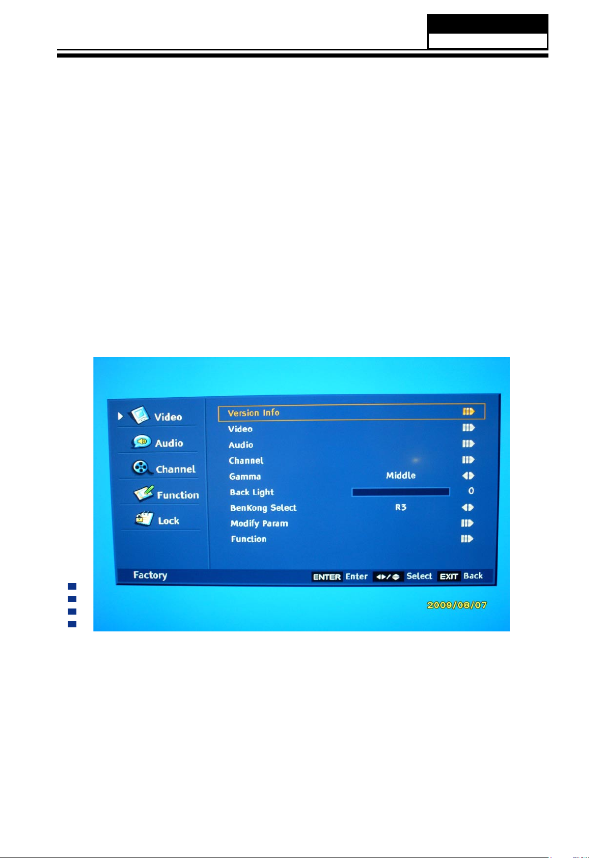
8-1-1.How to enter into Service Mode
The way to the factory mode menu:
Step 1: Press Menu,
Step 2: Input 8893,
Step 3: Press “OK”
System will be into the factory mode menu when 3 steps above are done.
8-1-2.How to exit
If you want to exit this factory menu, please press the button ”Exit” on the remote.
8-2. Measurements and Adjustments
8-2-1. Version, S/N, Panel Resoution
Version info: The first item is the Model Name and the second one is current software version.
(See picture on the next page.)
Page 49

Service Manual
Model No.: HL42XZK42
48
8-2-2. Video
Auto Color
The option could only be used in the VGA and Component model. When we found the color in
the two models was abnormal. Then we can use the function to adjust it automatically.
Color Temperature
The function could adjust the Color Temperature, used when debugging
Page 50

Service Manual
Model No.: HL42XZK42
49
8-2-3. Audio
Dolby Banner: When turn it “ON”, the model will be in Dolby authentication state.
Compression: Compression style. RF atv line AV/S-Video/YPbPr/VGA
Compression Factor: Compression state.
Downmix: output model. MTS System: used when debugging. The parameters only used when
debugging, no need to be modied.
8-2-4. Channel
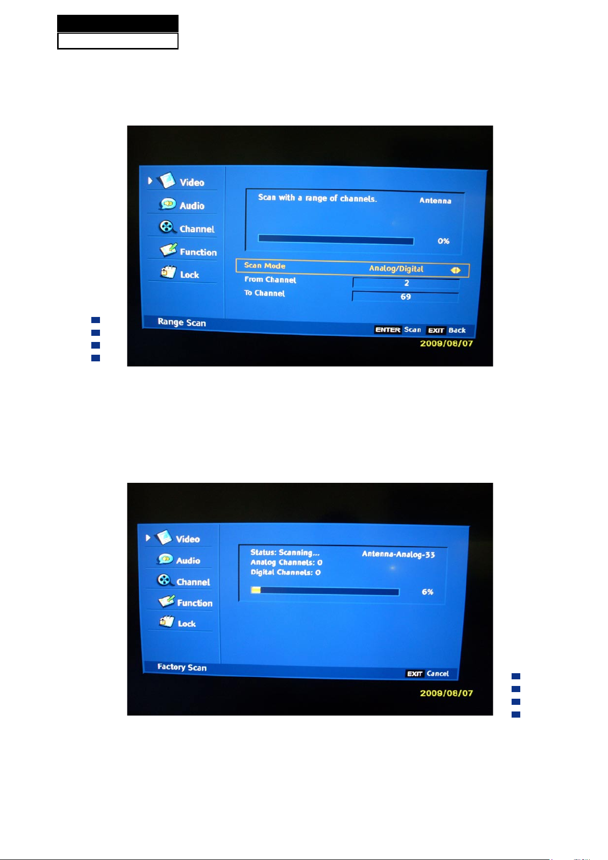
Range Scan: The function could make it to search the channels by differentiation the analog
and digital channels.
Page 51
Service Manual
Model No.: HL42XZK42
50
Single RF Scan: Search channels in the frequency scope set in advance.
Factory Scan:
According to ANTENNA-ANALOG---ANTENNA-DIGITAL---CABLE- ANALOG---CABLE- DIGITAL
to search channels, used only in project debugging.
Tuner Diagnostic: Project debugging setting, used to inspect the audio function.
Page 52

8-2-5. Gamma
Service Manual
Model No.: HL42XZK42
51
Gamma:
Bright GAMMA0.8 Middle default settings in the program Dark GAMMA1.2
8-2-6. Backlight
Backlight: adjust the backlight.
Page 53
Service Manual
Model No.: HL42XZK42
52
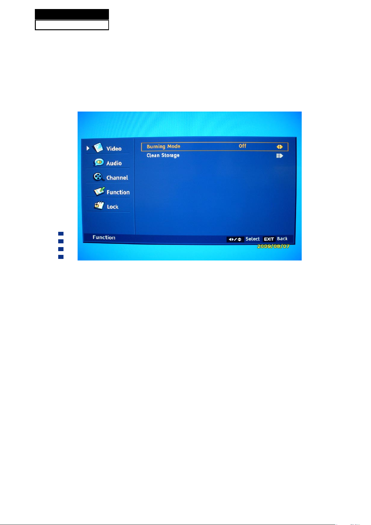
8-2-7. Function
Burning Mode:
Turn it “ON” to enter the aging model, This is for factory run-in testing. The screen would display
red, green, blue and black screen repeatedly. Each color screen could be exam at that time.
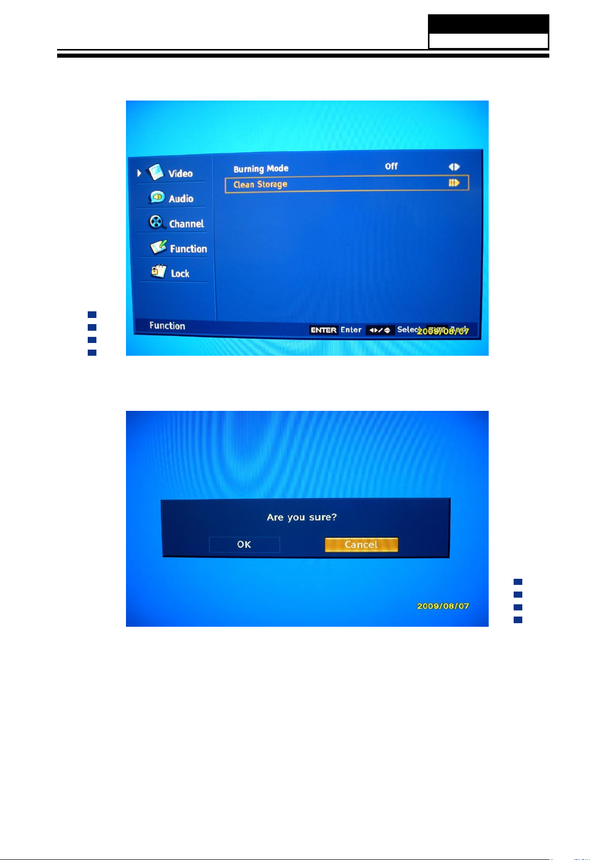
Clean Storage The function could make the model turn back to the factory default setting.
Page 54
Service Manual
Model No.: HL42XZK42
53
Remark:
The date of the chart only is an example, please don’t adjust the factory mode base on it.
Page 55
Service Manual
Model No.: HL42XZK42
54
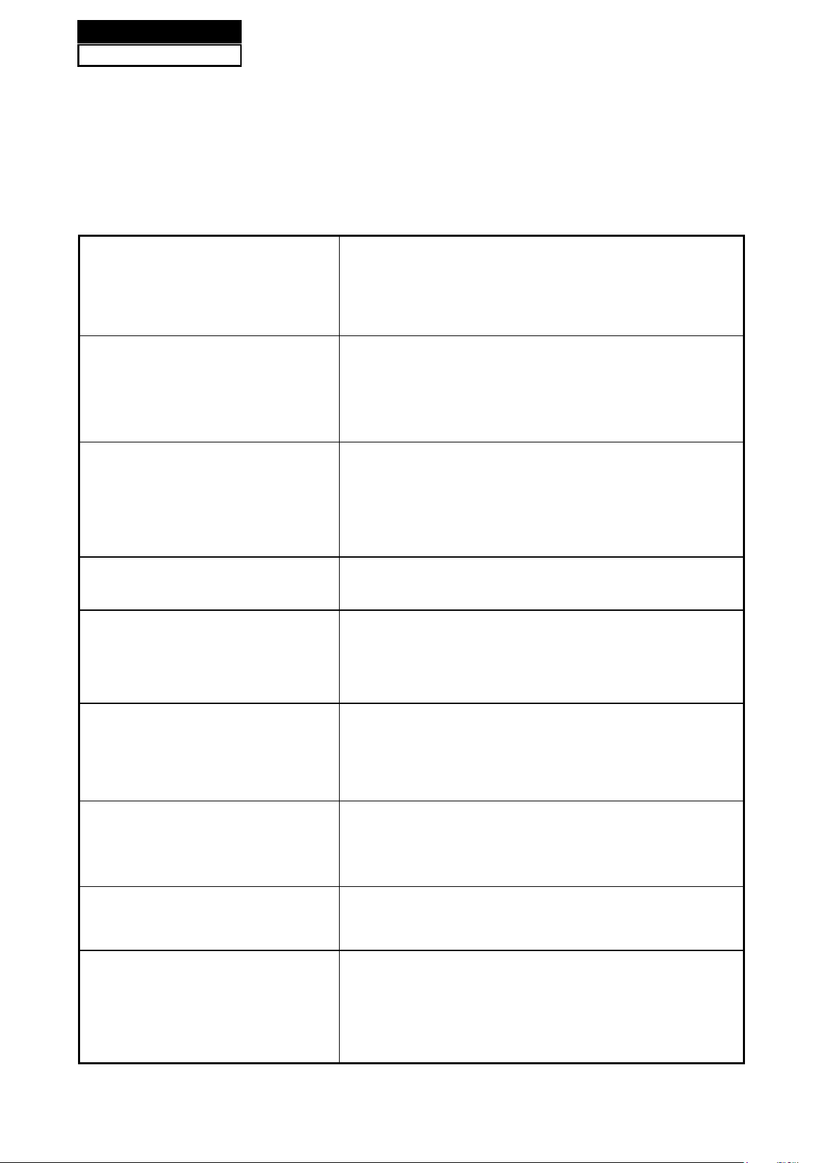
Chapter 9. Trouble shooting
9-1. Simple check
Verify if the television is properly plugged
No picture/ No sound
Blank screen
Verify if the television is properly supplied power
Verify if electricity is available.
Verify if correct signals are input
Press INPUT button to change signal input to TV input
Restart the television of power supply is interrupted
No sound
Poor sound
No picture in some channel
No color for some channel
program (black and white)
Spots with some or all pictures
Press Mute button and verify if Mute mode is set.
Switch to otger channel and verify if the same problem
happens.
Press VOL+ button to see of he problem can be
solved.
Verufy if sound system is correct .Refer to some
chapter for adjust.
Verify if correct channel is selected.
Adjust the antenna.
Make adjustments by Fine Tune and MANUAL Scan.
Verify if the same problem exists in other channels.
check out of picture and sound system.
Refer to relative instructions in the Manual for color
adjust.
Verify if the antennal is correctly connected.
Verify if the antennal is in good condition.
Make ne adjustment of channel.
Horizontal/ vertical bars or picture
shaking
Television out of control
Check for local interference such as an electrical
appliance or power tool.
Disconnect the television from power supply and 10
seconds later, connect the television to the power
supply. If the problem still exists, contact authorized
after-sales service for technical assistance.
Page 56

9-2. Power Supply Board Failure Check.
Service Manual
Model No.: HL42XZK42
55
Page 57
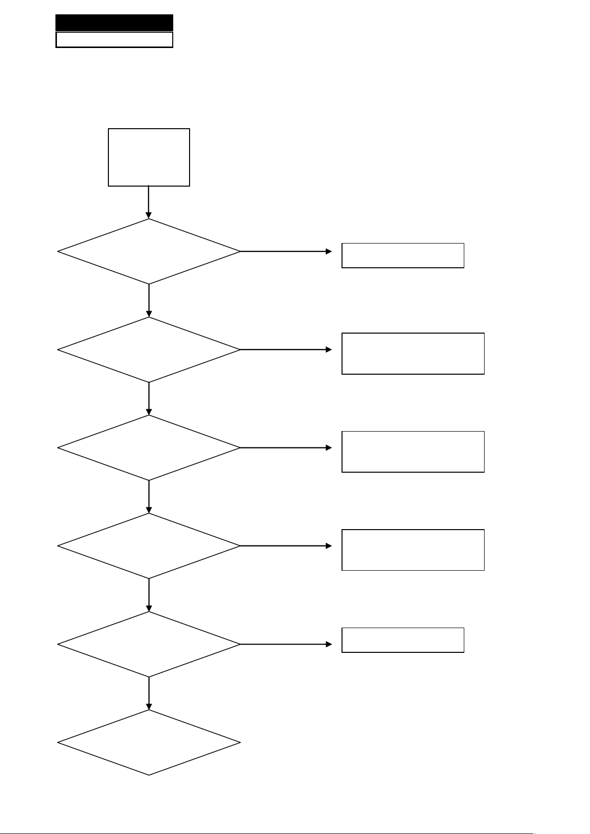
No Sound
(All Mode)
Check the input
Source
Change Source input
Check the
input/output
Re-soldering or change
IC U13
Check the
input/output
Re-soldering or change
IC U55
Check the
input/output
Re-soldering or change
IC U2
Check the
Speaker
Change the Speaker
Check the
Sperker wire
Service Manual
Model No.: HL42XZK42
56
9-3. Mainboard Failure Check
Symptom: No Sound
Fail
Pass
Pass
Pass
Pass
Fail
Fail
Fail
Fail
Pass
Page 58
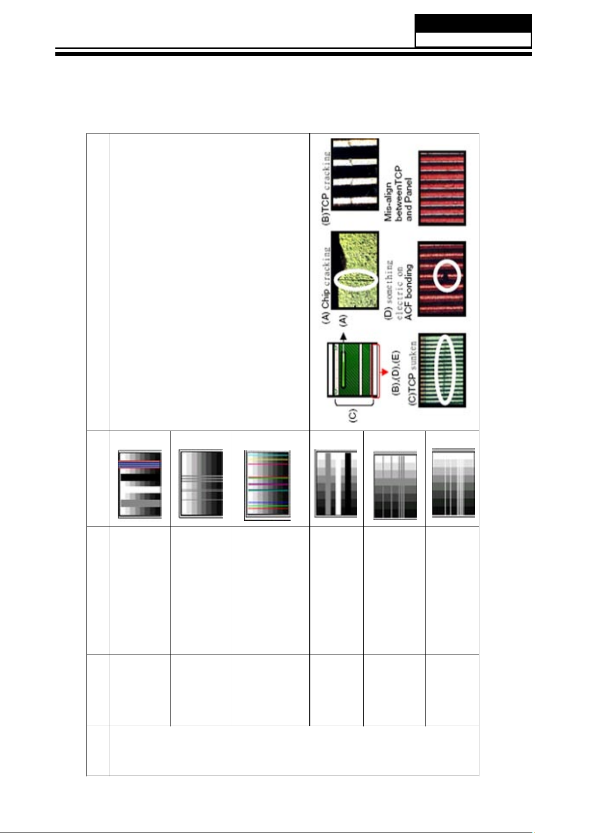
9-4. Pannel Failure
Service Manual
Model No.: HL42XZK42
57
Failure Mode
Block Defect :TCP cracking or cracking
Dim or L/D :TCP Sunken
:TCP lead cracking
:ACF bonding short
:Awful environment and
something electric enter
into LCD
:Mis-align between TCP and
Panel
:Panel failure
:TCP failure
Vertical color line(light or
dark forever)
Horiz o n t a l line(light or
dark forever)
V B/D Vertical bar
Part Name Description Phenomena Failure cause
V Dim Vertal gray line
V L/D
TCP
H B/D Horizontal bar
H Dim Horizontal gary line
H L/D
Page 59
Service Manual
Model No.: HL42XZK42
58
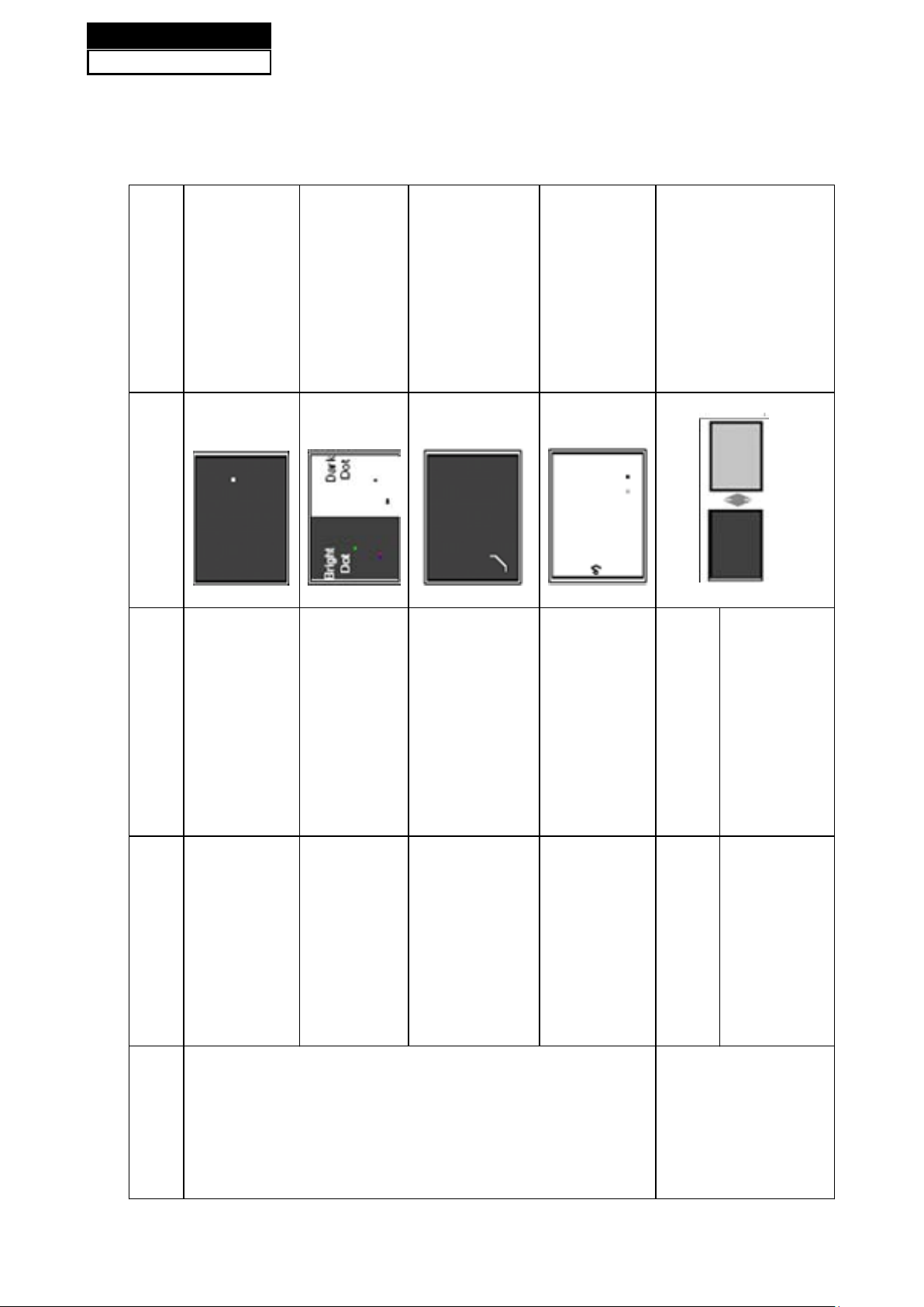
Bladder between Polarizer and
top glass
1.Chip lose action
2.IC ahort or jointiog bad
3.Pannel and vsc connect bad
Dot Defect Bright dot dark dot in pannel Incoming Inspection Standard
Polarizer Bubble Bladder in Polarizer
Polarizer Scratch Polarizer Scratch Tine or rigidity arose
F/inside Polarizer Eyewinker inside Polarizer Eyewinker inside Polarizer
Abnormal Display Abnormal Display
Flashing Bright and dark display alternately
Part Name Description Phenomena Failure Cause
Circuit
Panel or Polarlzer
Page 60
Service Manual
Model No.: HL42XZK42
59
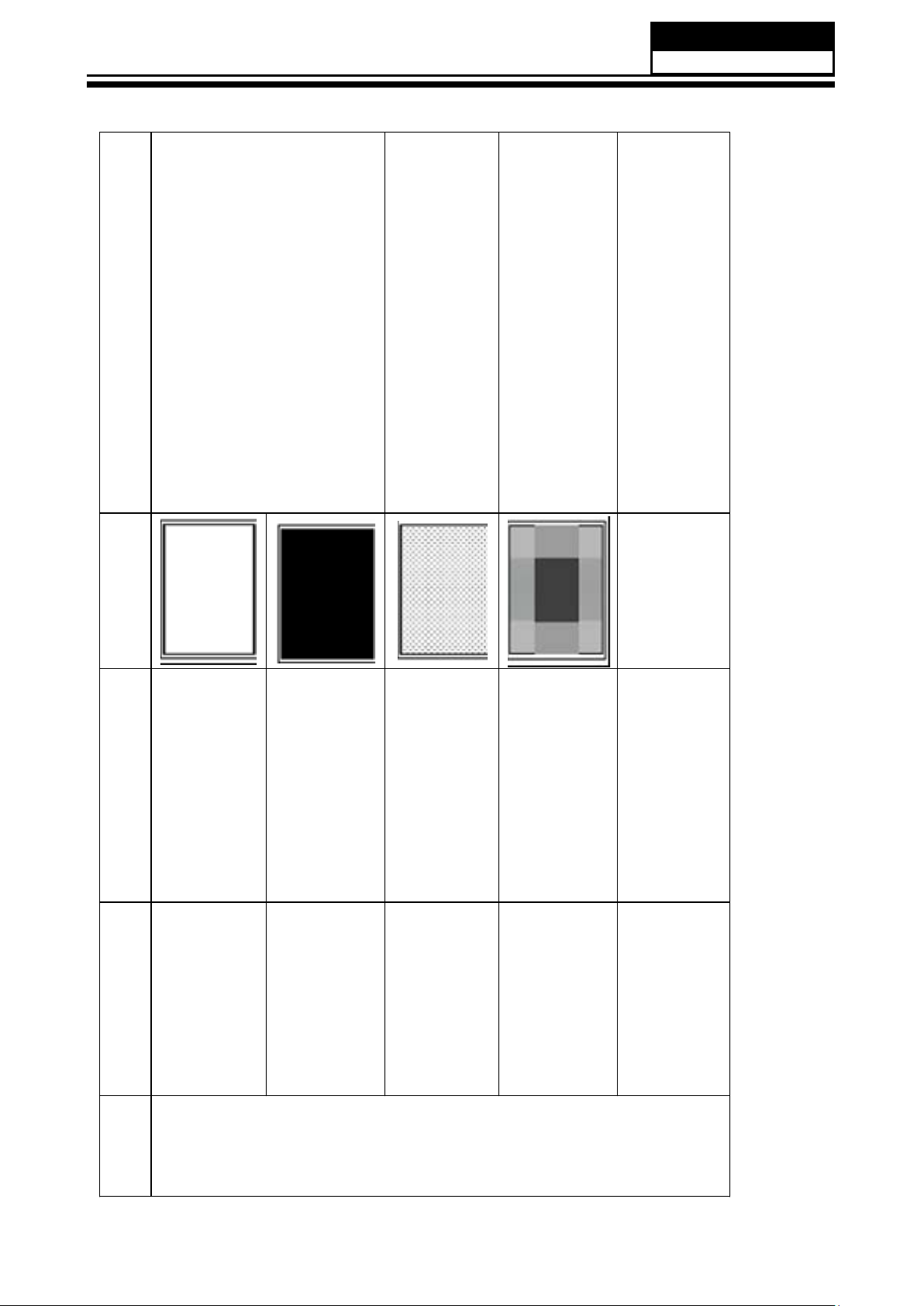
Maybe caused by surge current and EDS
B/L normal,
only white screen display
B/L normal,
LCD
Vcom imbalance
only Black screen display
Capacitance
improper bring crosstalk inside LCD pannel
Only
color abormal
1.Chip
lose action
2.IC short or jointion bad
3.Pannel and vsc connect bad
Only
color abnormal
White Screen
Part Name Description Phenomena Failure Cause
Black Screen
FIIcker Crosstalk
Circuit
Abnormal Color
Abnormal Color
Page 61
Service Manual
Model No.: HL42XZK42
60
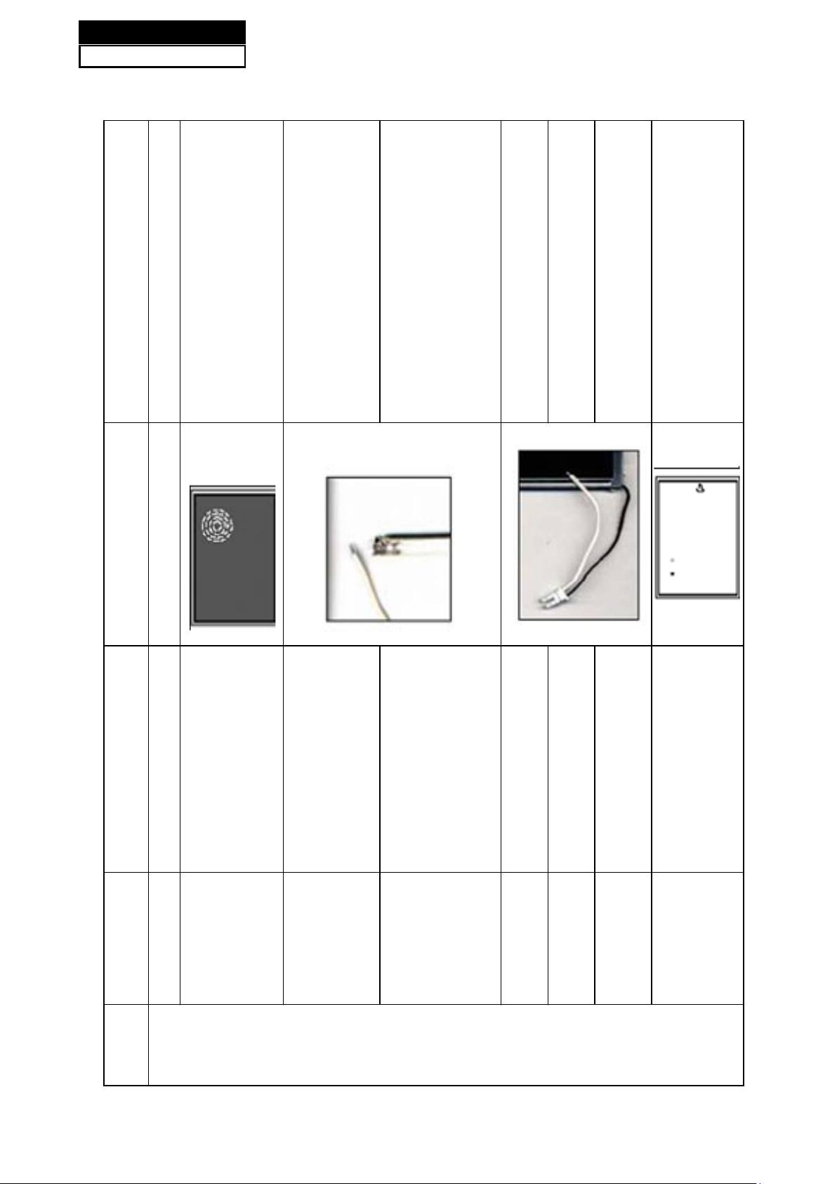
Caused
by Mechanica noise of backlight unit
Causeed by
between
mechanism and pannel
*Connect
badness
between wire and electrode
*Connect
badnessShort between wire and electrode
Operation
abnormal
or systemic noise
Operation
abnormal
or systemic noise
Short bitween lamp housing and wire, Because
consume power too much
F/M in B/L unit
When
turn panel,appear cacophony
Nolse
Mechanlcal
Part Name Description Phenomena Failure cause
Ripple Connectric circle
B/L off B/L lose action
normal
B/L brightness darker than
B/L dark
B/L
wire damaged
B/L
wire damaged
B/L wire open Without backlight
B/L shut down B/L shutdown in sometime
F/M
or wirelike
inB/L ,white,balck Rotundity
F/M
Page 62

B/L unit badness
Service Manual
Model No.: HL42XZK42
61
Sheet in B/L unit is uneven
*Lack screw
Screw damage
Brightness
than normal
at bottom of LCM brighter
Light leakage
Part Name Description Phenomena Failure Cause
Lack screw
Uniformity B/L brightness asymmetric
Mechanlcal or B/L
or screw damage
Mount hole
Page 63
Sincere Forever
Haier Group
Haier Industrial Park, No.1, Haier Road
266101, Qingdao, China
http://www.haier.com
Printed in China
 Loading...