

Page 1
Page 2
If you have any questions please contact
Ithe Customer Care Department as indicated on the warranty card
Page 3
Page 4
Water dispenser
Page 5
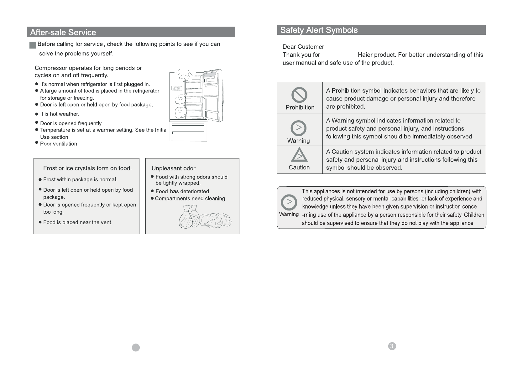
are observed:
purchasing a
please ensure the safe symbols
35
Page 6
water filter
36
Page 7
Safety Precautions
Place
number
6
34
Page 8

33
Page 9

31
Page 10

away from high
32
Page 11

Page 12

30
Page 13

Assembly of the Door Handle
Please follow the instructions below when assembling the Refrigerator Door Handle:
in reverse.
removing
please follow the instructions
Attention:
Please do not disassemble the Refrigerator door handle.
If the handle must be taken apart please contact a qualified technician.
29
Page 14

Please follow the instructions below when assembling the Freezer Door Handle:
Please do not disassemble the Freezer door handle. If the handle must be taken
apart please contact a qualified technicia
n.
See page 12 for instructions on how to connect the water.
ԡ
28
Page 15

Removing and replacing the freezer drawer and ice bin
Removing and Replacing FreezerDrawer
filter
Assembling the water connection
For water dispenser product only
Contents of filter kit
1 4 m (13 ft) white 6 mm ( ”) tubing
2 1 x 200 mm (8”) blue tubing
3 1 x pressure reducing valve (PRV)
4 1 x double sided foam
5 2 x locking keys
6 1 x water filter cartridge and head
7 1 x tap connection – 15 mm ( ”) BSP
1234567
Freezer Drawer
Fig.1 Water connection kit
Important!
• It is imperative the pressure reducing valve (PRV) is fitted prior to the filter. This valve ensures the
water will not flow back into the mains from the refrigerator water system. If the PRV is not fitted to the
connection line your Ice & Water refrigerator features may not function in some circumstances.
• It is recommended that an authorised plumber in your state or town is used to install the water
connection.
• The new tubings supplied with the refrigerator are to be used, old tubings from old Ice & Water
connections should not be used.
Installation precautions/warning
• DO NOT use with water that is microbiologically unsafe or of unknown quality without adequate
disinfection before or after the system.
• WARNING – connect to potable water supply only.
• DO NOT install on line pressure above 900 kPa (130 psi) or below 150 kPa (22 psi).
• DO NOT use on hot water supply (38°C [100°F max.]).
• DO NOT install near electrical wires or water pipes that will be in the path of drilling when selecting
the location of filter system.
• DO NOT mount filter in such a position so that it will be struck by other items, such as wastebaskets,
etc.
• DO NOT install the filter in direct sunlight as prolonged exposure to light can weaken plastic
components.
• DO NOT install in a location that is susceptible to freezing temperatures as damage to the housing
could occur.
• DO NOT screw filter to fridge.
• AVOID contamination of pipes during installation.
• DO NOT use copper tubing. The plastic tubing supplied should always be used.
27
Page 16

18. The first time you require water out of the dispenser, there will be a delay while the water
reservoir fills up.
19. Run a further 3 litres (3 qt) through the system, stopping intermittently to ensure the reservoir
is flushed out. Failure to do this will result in excessive dripping from your dispenser.
Important!
• All connections must be checked for leaks.
• If unsure of connection process and/or leaks then contact your local plumber to
install and check the system for you.
• Ensure white 6 mm (¼”) tubing is routed away from sharp objects, sharp
corners (beware of kinking tube as this will stop water flow), clear of the
refrigerator unit compartment and not in a location where it can be squashed.
• Ensure all push-fit connections are firmly pushed into place. The tube should
push in 20 mm (¾”) before reaching the stop.
• If tubing is removed at any point, re-cut the end and re-insert. Tubing must be
fully inserted to avoid leaks.
• To remove tube from connection points, turn off the isolating tap, push in the
collet and gently pull tubing at the same time.
vegetables
Fig.8 Connection to water supply
Diagram 9
Refer to page 26, About Freezer compartment, for instructions on the first use
of the ice maker and water dispenser.
How to Use the Water Dispenser
Available on some models
FRZTEMP
FUNCTION
REFTEMP
ok
1.Push the dispensing pad gently,using a glass cup.
2.If you want to stop the flow of water,release from the dispensing pad.
24
Page 17

First Use
When preessing the water dispenser tab the first time you may not get water out as air will be in the
g
Please throw away the first 5 cups of water to remove any impurities in the lines.
g
If you like very cold water first add some ice cubes from the ice storage box.
g
Do not put hands or other items into the water dispenser or ice storage box.
Water Dispenser Precautions
Changing the water filter cartridge
C
Change the filter after 6 months.
It is not necessary to turn off the water supply before attempting to change the water filter
cartridge.
1 Grasp and firmly twist the cartridge in an anticlockwise direction (to the left when installed
in the recommended orientation) as shown in Diagram 1.
2 Pull the cartridge away from the filter head (down when installed in the
recommended orientation) as shown in Diagram 2.
– It is not unusual for a few drops of water to be present when the filter is removed.
3 Discard old filter.
4 Filter installation:
– Remove protective cap on spigot on head.
– Push the cartridge up towards filter head while rotating it in a clockwise direction (to
the right when installed in the recommended orientation) as shown in Diagram 3
5 Dispense 10 L (10 qt) to flush the cartridge, removing trapped air and harmless carbon fines.
11. Attach double sided foam to the back of the water filter head as shown in
Diagram 5. Write the date to be replaced on the filter (date installed + 6
months). Remove double sided foam backing and attach filter to the
desired position as located in step 10 (refer to previous page).
12. Run the 6 mm (¼”) tubing to back of the fridge ensuring there is enough
tubing to pull out the refrigerator for service.
13. Connect tubing into the water (solenoid) valve located on the right hand
side of the unit (compressor) compartment as shown in Diagram 7.
Beware of hot pipes.
14. Pull gently on tubing to ensure it is locked in as shown in Diagram 8.
15. The completed installation should look like Diagram 9 on page 15.
Diagram 7
Diagram 8
Diagram 5
Fig.6Double sided
foam attachment
25
Diagram 6
Fig.7
16. Turn isolating tap on and check that all connections are dry and free of drips. If not, please
alert the plumber.
17. Coil water line tubing behind the fridge. Push your refrigerator into place being careful not to
kink or squash the water line running into the water (solenoid) valve.
Page 18

Installation instructions:
1. Ensure that refrigerator is not plugged into a power
supply.
2. Locate isolation tap for water connection – cold water
feed only (dishwasher or sink mixer taps) – if you can’t
find the connection tap, contact an authorised plumber in
your state or town to fit your water connection. Tee and
tap fitting not supplied.
3. Connect the 200 mm (8”) blue tubing to the outlet of the
PRV (blue collet) and the inlet connection of the water
filter cartridge as shown in Diagram 1. Gently pull on both
ends to ensure it is locked.
4. Connect the white 6 mm (¼”) tubing to the outlet of the
water filter cartridge as shown in Diagram 2. Gently pull
to ensure it is locked.
5. Measure the required length of tubing to run from the
PRV to the water connection point.
6. Cut the tubing making sure the ends are square and
clean.
7. Connect the tubing to the tap connection and the base of
the PRV (white collet) and then to the tap as shown in
Diagram 3. Please note that the tap connection supplied
should fit most installation situations. If your tap requires
a different fitting, please contact an authorised plumber in
your state or town to purchase the correct fitting.
8. Connect one locking key to each side of the water filter
cartridge in between the cartridge and the locking collet
as shown in Diagram 4.
9. To flush the water filter and check for leaks, aim the end
of the tubing into a bucket, turn isolating tap on and run
at least 3 L (3 qt) of water through. Once complete, turn
isolating tap off.
10. Locate desired position for water filter noting carefully the
following points:
• It is recommended to fit the water filter in a vertical
orientation with the water filter head at the top. This
will minimise water leakage when replacing cartridge.
• Ensure the filter is in a convenient location to access
every 6 months for replacement. We suggest that this
location is beside the water filter supply tap in a
cupboard beside the refrigerator.
• A minimum clearance of 64 mm (2 ½”) from the
bottom of the filter cartridge is required to perform
cartridge removal.
• Do not screw the water filter to refrigerator.
Diagram 1
Fig.2 PRV connection
Diagram 2
Fig.3 Waterline connection
to refrigerator
Diagram 3
Fig.4 Tap connection
INLET
have an
To turn the ice maker on and off
press (Function) button to scroll to the ( ) screen,( )light on then press(ok),ice maker is turned on.
press (Function) button to scroll to the ( ) screen,( )light off then press(ok),ice maker is turn
ed off
.
Diagram 4
Fig.5 Locking key
26
Page 19

9
7
Adjustment
9
To ensure normal operation,allow the appliance to stand
still for 6 hours.
Page 20

Control panel
Page 21

Page 22

 Loading...