

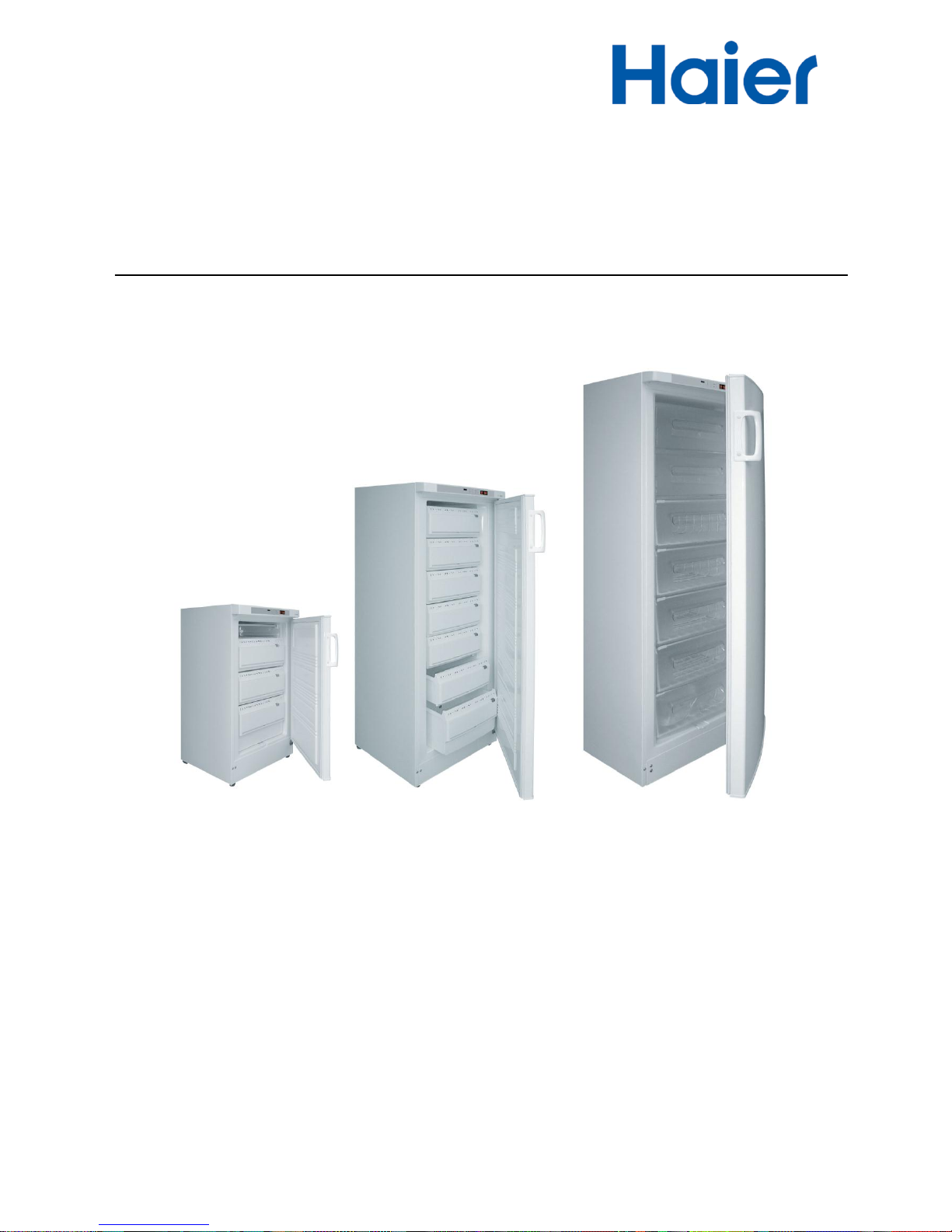
Service Manual
Deep Freezer-upright
DW-25L92•DW-40L92•DW-40L188•DW-25L300•DW-40L262
Haier Medical & Laboratory Products Co., Ltd.
FILE No: HMRSM-02-002

2 / 33
Effective models
This service manual is effective for following models
Model name
Product code
Voltage(V)
Frequency(Hz)
Plug-type
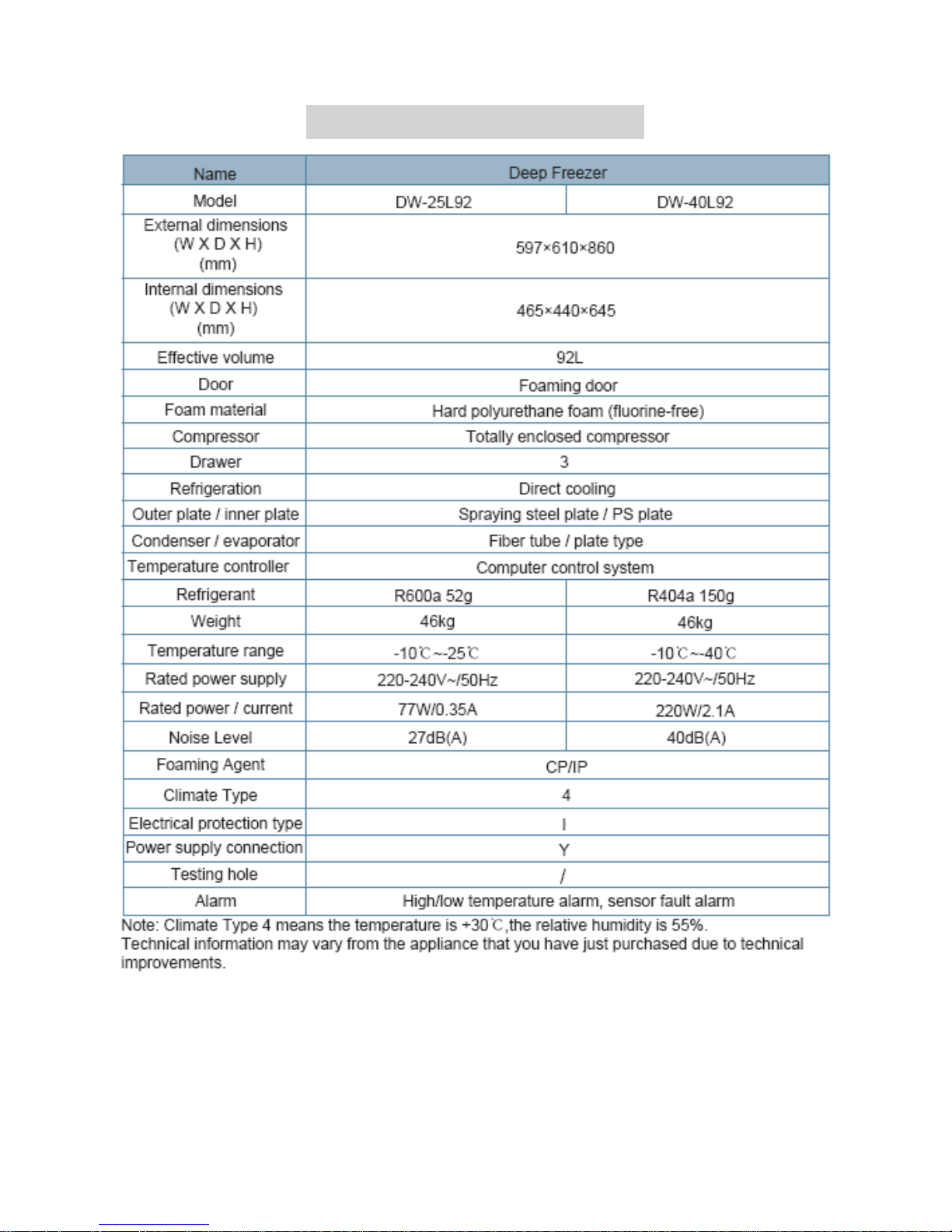
DW-25L92
BE02M9E0N
220-240
50
English Standard
英式三扁(flat)
DW-40L92
BE02M8E0N
220-240
50
EU Standard
欧式两圆一孔
BE02M7E0N
English Standard
英式三扁(flat)
DW-40L188
BE02P1E1T
220-240
50
EU Standard
欧式两圆一孔
BE02P2E1T
English Standard
英式三扁(flat)
DW-25L300
BE02QDE0N
220-240
50
English Standard
英式三圆(round)
DW-40L262
BE02Q4E1T
220-240
50
EU Standard
欧式两圆一孔
BE02Q3E1T
English Standard
英式三扁(flat)
BE02Q5E1T
English Standard
英式三圆(round)
BE02QBE0N
50/60
English Standard
英式三扁(flat)
BE02Q0E0A
America Standard
美式
BE02QCE0N
115
60
America Standard
美式

3 / 33
Content
【Designation】 .......................................................................................................................................................... 4
【Safe Caution】......................................................................................................................................................... 5
【Product appearance】 .............................................................................................................................................. 6
【Product Specifications】 ....................................................................................................................................... 10
【Components and Function Modules】 .................................................................................................................. 12
.【Disassemble Steps】............................................................................................................................................. 14
【Disassemble Steps】.............................................................................................................................................. 14
【Screen Control System】....................................................................................................................................... 16
【Control System Principle】 ................................................................................................................................... 18
【System Schematic Diagram】 ............................................................................................................................... 19
【System Circuit Diagram】..................................................................................................................................... 20
【Inspection and Maintenance Process for Typical Error】 ..................................................................................... 21
【FAQ&A】 .............................................................................................................................................................. 22
【Cooling unit parts】............................................................................................................................................... 23
【product nameplate】 .............................................................................................................................................. 24
【Refrigerant perfusion Details】 ............................................................................................................................. 26
【Troubleshooting】 ................................................................................................................................................. 27
【How to deal with poor cooling】........................................................................................................................... 26
【Used Spare Parts Photo Gallery】 ......................................................................................................................... 27
【Testing Date】 ....................................................................................................................................................... 28
4 / 33
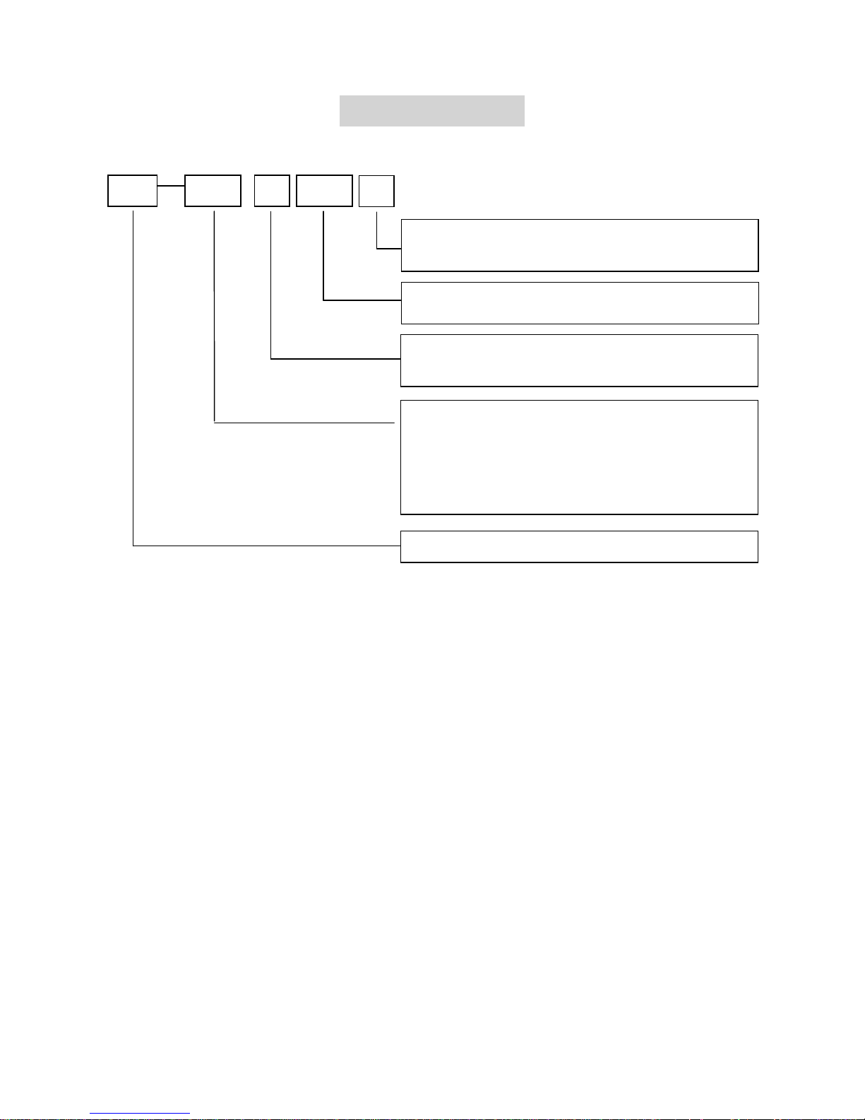
【Designation】
Regulations for type naming:
Note: rated volume can be the gross volume or effective volume; the manufacturer can decide it by
him according to the actual situation. The effective volume value must be marked on the nameplate
whether effective volume or gross volume is marked in the product name.
Examples:
DW-40L262 means that the Deep temperature storage refrigerator with the temperature at
characteristic temperature -40℃, horizontal and rated effective volume 262L.
DW
XX X XXX
X
Design No. is expressed with pinyin character
sequence
Rated volume value is shown with L
Classification of low temperature cabinet (W is
horizontal and L is vertical)
It shows the temperature at the characteristic point
inside cabinet (without minus mark)
(For example: temperature at the characteristic point
inside cabinet -40℃ can be expressed as 40)
Low temperature cabinet
Deep temperature cabinet

5 / 33
【Safe Caution】
1. If the voltage used is 10% higher or lower than rated voltage, an auto stabilizer above 1000W shall be
equipped. Power line that required for lengthening shall be with a cross section no less than 1mm.
2. An independent private jack shall be used and reliably connected. The power line for refrigerator is
equipped with three-wire, grounding-type plug which meets standard three-wire, grounding-type
receptacle. In no circumstance should the third plug foot (grounding) of the power line be cut or removed.
The plug shall be touchable after installation of refrigerator. Power line or plug with abrasion shall not be
used. Abraded or damaged power line shall be sent to maintenance point designated by the manufacturer
or be replaced by qualified personnel.
3. Hazardous articles of inflammable, explosive, materials such as acid and alkali with strong corrosion
are prohibited in the refrigerator.
4. Please don’t use flammable spray closely to avid fire.
5. When there is inflammable gas such as coal gas leakage:
● Shut the valve for leakage;
● Open the door and window for ventilation;
● Don’t pull out or insert power plug of the refrigerator.
6. Prevent children playing in the refrigerator to avoid accident.
7. Once the power of the refrigerator is cut, it shall be re-connected at least five minutes later to avoid
damage on compressor or the system. The power shall be cut for maintenance. Do not roll or damage the
power line.
8. Please wear protective equipments during accessing to the refrigerator to avoid freezing injury. When
the refrigerator is scrapped, please remove the doorman. The scrapped refrigerator shall be away from
fire and be sent to appointed site for disposition.

6 / 33
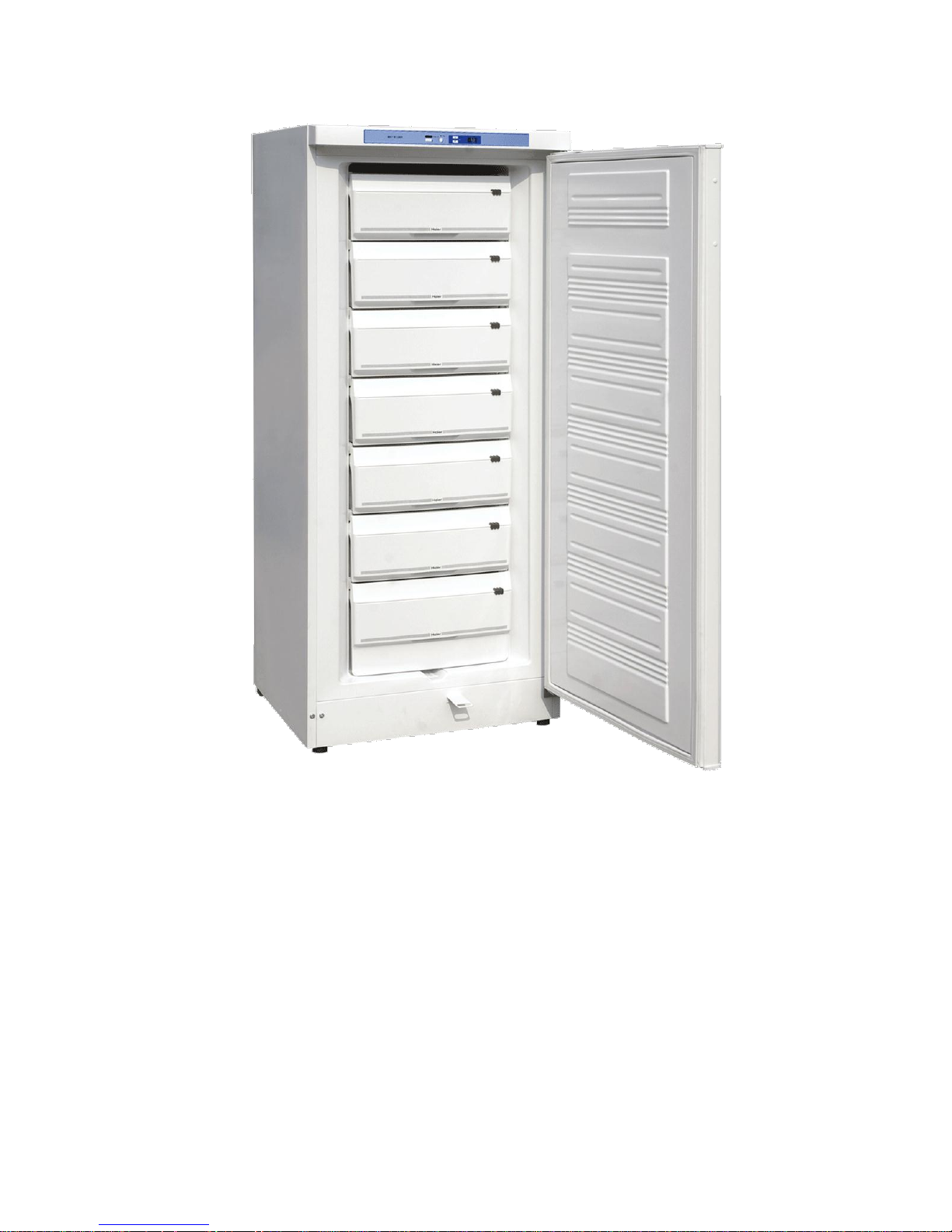
【Product appearance】

7 / 33
8 / 33
9 / 33
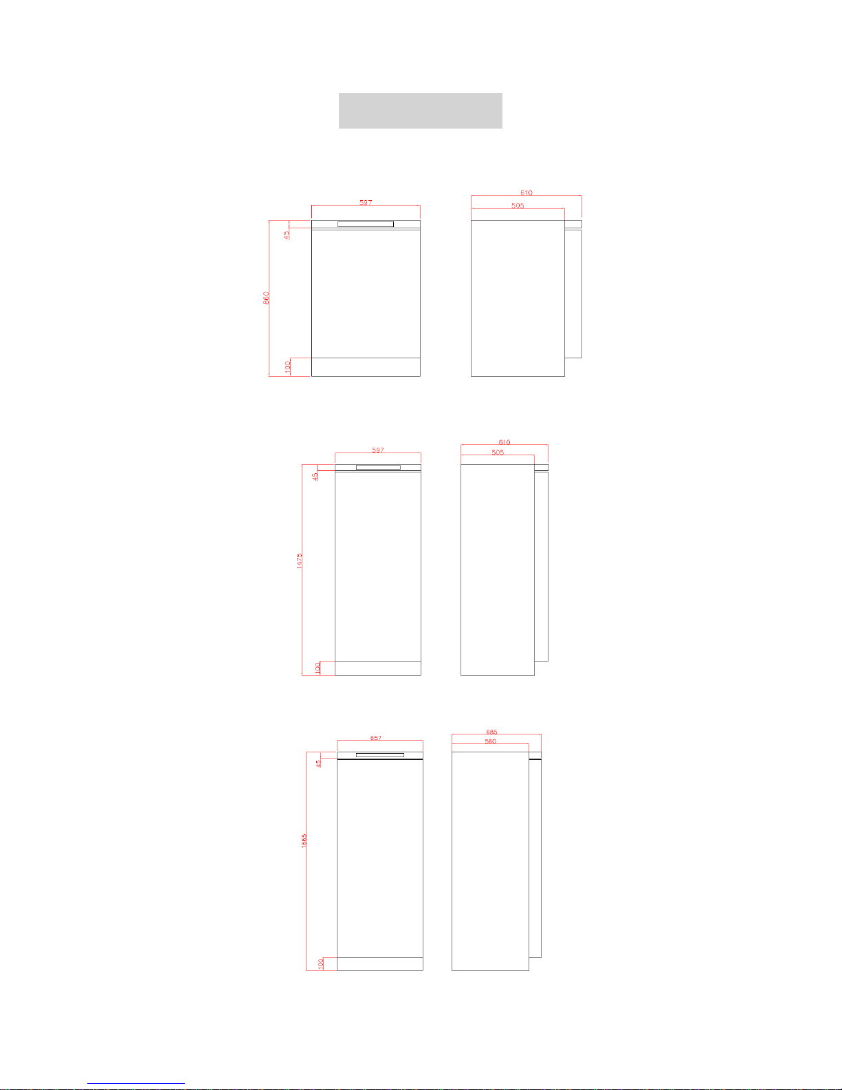
【Dimensions】
DW-25 L92/ DW-40L92
DW-40L188
DW-25L300/DW-40L262
10 / 33
【Product Specifications】

11 / 33

12 / 33
【Components and Function Modules】
1. Temperature control
It is controlled by microcomputer with digital display for temperature while the inner temperature can be
adjusted from -10℃~-25/-40℃; there is parameter setting for super low temperature alarming and break
down memory.
2. Safety system
2 error alarming (high/low temperature alarming, sensor error alarming
2 alarming methods (sound buzzing alarming, red light alarming)
Starting up delay protection function
3. Refrigerating system
Imported famous brand SECOP/DANFOSS compressor is adopted
Environment protection free refrigerant
German famous brand EBM fan
High density insulation layer with heat preservation
The evaporimeter is used as rack directly for speed refrigeration.
4. Humanity design
Drawer design for convenient utilization
LED digital temperature display for convenient observation
Broad voltage belt suitable for voltage
Doorknob design for easy on and off
Trundle design for convenient motion
Gate locks design for safe storage

13 / 33
5. Product graphical representation
Remark:
For DW-25L92 Series or DW-40L92 Series, please take out the suite of lock catch from the
accessory and install the lock catch on the left side of the box according to “Lock Catch Installation
Instruction leaflet”
The press is located in the cabin on rear bottom of the refrigerator with cabin cover
The condenser is located at rear of the refrigerator.
The evaporimeter is located inside the refrigerator as rack

14 / 33
.【Disassemble Steps】
1. Install the Handle
① .Align the handle to the screw hole on the door;
② .Use screw to fix the handle.
2. Disassemble steps for control board
Unscrew the following screws mark ed 1 and 2 in following figure, the control board can be
fetched.
Attention: there are wires connecting control panel and refrigerator as shown in following:

15 / 33
The following is details for connection of computer board and ports;
Mark “1” in the above figure is connecting port for power line to connect power line; mark “2” in the
above figure is sensor port to connect sensor line.
3. Installation steps for control board
Installation shall be according to 2-4 disassembly steps oppositively.

16 / 33
【Screen Control System】
1 External view of computer board
2 Basic parameters for computer board
Rated power 3W
Control current for press under normal operation shall be no more than 10A
The 30 seconds start delay for the first energization of press . In normal operation, each time it is
shut down, start timing, the compressor will not start if the start up time is less than 5 minutes; if the time is
over 5 minutes, please take the actual time for operation.
3 Temperature display function
The actual temperature displayed is integer. The measured value is rounded off to integer. in
normal situation, the temperature shall not hop, with all temperature variable being ±1℃/min;
The display range is from +34℃ to -45℃, with temperature higher than +34℃, displaying “HH”;
with temperature lower than -45℃, displaying “LL”.
4 Quick-freeze setup function
Press quick-freeze button to light indicating light SF, indicating that the refrigerator is in operation;
press the button again to release the status, or it may be released automatically after three hours.
Temperature can not be set under quick-freezing status;
5 Overheat alarming function
When the actual temperature sensed by the sensor is higher +5℃ higher or lower than set
temperature, the overheat alarming light will flicker (with interval of 1S), accompanies by buzzing (with
interval of 0.5S). Press the buzzing releasing button to release buzzing; but the red light will keep on
flickering (press again can not recover buzzing. It is only when the temperature is within +5℃ upper or
lower than set temperature or cut the power, the buzzing releasing button can reset to recover buzzing
function).
Note: if the freezing sensor is in error, the red light may keep on flickering with interval of 1S and
alarming fail.
6 Recovery processing and error display of freezing sensor
When the freezing sensor is in error (short circuit or open circuit), the temperature value displayed
will be “F1”; the frozen food cabinet enters protecting mode and compressor is in fixed alternation of
20min on and 5min off with alarming in failure; if the refrigerator is in quick-freeze status, quit (the
corresponding light will be off).
7 Break down memory function
When the frozen food cabinet is broken down and electrified again, the memory function can
operate according to status set before breaking down.
Display control>quick freeze>normal control F1 display >temperature display

17 / 33
8 Temperature adjustment principle and alignment
This machine adopts microcomputer controlled temperature control system to control on-off of the press.
In electrified condition, the screen may display current temperature. If you want to change the set
temperature, for example, change from -30℃ to -35℃, please operate as following:
Press both “∧” and “∨” for 3 seconds, the set temperature starts flickering. Press “∧” once, the
temperature will decrease by 1℃ until it reaches -40℃, and then press back to -10℃; press “∨” once, the
temperature will increase by 1℃ until it reaches -10℃, and then press back to -40℃; if there is no 5
second operation, quit the setting status back the normal temperature display.
Press “quick-freeze”, “△ ” and “▽” simultaneously for 5 seconds to align difference between displayed
temperature and set temperature at certain point, with aligning temperature being ±5℃. If the displayed
temperature is -40℃ and temperature of certain point is -35℃, enter +5℃ to make display temperature
-35℃, vice versa.
Press alarm, cancel and temperature set for 10 seconds, the screen display HS. Press two temperature
setting buttons simultaneously, the number on screen flickers; press “△ ” and “▽” to set highest
temperature and then loosen. It will quit automatically in 3 seconds and the screen now displays LS.
Press two temperature setting buttons simultaneously, the number on screen flickers; press “△ ” and “▽”
to set lowest temperature and then loosen. It will quit automatically in 3 seconds.
Note: a. temperature range for HS and LS is 10~42℃。
b. When setting temperature for HS and LS, the HS value shall be higher or equal to LS, or it can not be
set.
c. Once the HS and LS are set, press both temperature setting buttons simultaneously. The set
temperature shall be set within HS and LS (including) only.
d. When both HS and LS are set -25, the set temperature shall be -25℃. Set temperature can not be
adjusted and the quick freeze function fails.

18 / 33
【Control System Principle】
1 Working principle for press on and off
When inner temperature reaches set temperature, induct the temperature by sensor and change into
electrical signal which is sent to control chip of computer board. By pre-set procedure, the chip then sends
out stop order to compressor to shut it down. When the inner temperature is returned 1℃ higher than set
temperature, the chip sends out stop order via the same procedure to shut the compressor down. (If
temperature return in the refrigerator is too fast, less than 5 minutes, then take it as 5 minutes.)
2 Working principle for fan on and off
The fan is in synchronous operation with the compressor. Please refer to 6-1 press working principle for
fan working principle.

19 / 33
【System Schematic Diagram】

20 / 33
【System Circuit Diagram】
21 / 33
【Inspection and Maintenance Process for Typical Error】
Problem points
Reason analysis
Maintenance measures
1. the press can not start
1. The fuse is burned out.
Change the fuse
2. Connecting parts of cabinet is
damaged.
Change socket connector.
3. The connecting line for electric
cabinet is not in right position.
Install correctly after inspection.
4. The temperature controller is in
error.
Adjust parameters. If the
temperature controller is
damaged, change it.
5. The starter or thermal protector
is damaged.
Change the starter or thermal
protector.
6. The press is in error.
Change press.
2. High temperature inside the
refrigerator
1. The set temperature is high.
Reset
2. The freezing agent is leaking.
Find leaking point and weld. Refill
freezing agent.
3. The temperature controller is
damaged.
Change the temperature
controller.
4. The capillary or system is dirt
and stopped.
Clean capillary or change filter.
3. The screen
doesn’t display
temperature.
It displays
F1.
1. The temperature-sensing probe
is in short or open circuit.
Inspect the temperature sensing
probe.
2. Without temperature sensing
probe.
Install temperature sensing probe.
4. Big noise
1. The refrigerator is not even.
Change position of the refrigerator.
2. Sympathetic vibration between
pipelines or refrigerators when
press operating.
Clear up the pipelines to avoid
sympathetic vibration.
3. Fan and fan bracket is loosen.
Re-fix
3. Connection bolts of the press is
loosened.
Tight the inner connecting bolts.

22 / 33
【FAQ&A】
Question
Answers
Measures able to adopt
1. Inner temperature is too high or
too low.
Can be resolved by adjusting and
control of temperature.
See detailed operation in
instruction manual.
2. Sides of the refrigerator is hot.
There is anticoagulant near
refrigerator open on side surface.
Heating is normal instead an error.
Can turn off the electric heating
switch.
3. There is difference between
displayed temperature and
detected temperature.
The displayed temperature is
temperature on sensing probe. It
is normal to has difference with
that of the refrigerator.
Normal situation needs no
resolution.
4. The alarming rings in short time
after start up.
Alarm when the inner temperature
in within alarming region.
Normal situation needs no
resolution.
Why there is serious frosting in DW-25/40L series?
Answer: it may caused by loosen door or frequent opening the door, or one of the small hole allowing
condenser to enter the refrigerator is not plugged up. This needs to be disposed by service persons.
Moreover, regular defrosting is required to keep better effect, normally once per 1-2 months.
Error of DW-25/40L series sensors and how does press operate?
Answer: During the operation of DW-40L low temperature reserving box, when the freezing sensor is in
error (short circuit or open circuit), the temperature value displayed will be “F1”; the frozen food cabinet
enters protecting mode and compressor is in fixed alternation of 20min on and 5min off with alarming in
failure; if the refrigerator is in quick-freeze status, quit (the corresponding light will be off).
What is the temperature setting range for DW-25/40L series machine?
Answer: the set range is -10~-25/-40℃.

23 / 33
【Cooling unit parts】
Part decripetion
parameter
Models
Parameter
compressor
DW-40L92/188
Secop/Danfoss NL7CLX
power
220-240V/50Hz
Start capacitance
117U5015(80uF)
compressor
DW-40L262
Secop/Danfoss SC12CL
power
220-240V/50Hz
Start capacitance
117U5017(80uF)
compressor
DW-40L262
Secop/Danfoss SC12CLX.2
power
220-240V/50Hz/60Hz
Start capacitance
117U5019(80uF)
compressor
DW-40L262
Secop/Danfoss SC12CLX.2
power
115/60Hz
Start capacitance
117U5023(240μF)
compressor
DW-25L92/300
jiaxipera ZBC1115CY
power
220-240V/50HzHz
Start capacitance
TY-QZ-108
Refrigerant
DW-40L
R404a
Refrigerant
DW-25L
R600a
Fan motor
DW-40L
EBM AC230V/50/60Hz, 29/5W,1300rpm
Display panel
DW-25/40L92/188
0070809344 ,Haier PCB
Display panel
DW-25/40L262/300
0070809343 ,Haier PCB

24 / 33
【product nameplate】

25 / 33

26 / 33
【Refrigerant perfusion Details】
Type
DW-40L92
DW-40L188
DW-40L262
(220-240V/50 Hz /60Hz)
DW-40L262
(115V/60Hz)
DW-25L92
DW-25L300
R404a
150
210
220
200
R600a
52
90
[Note] refrigerant type and weight of the nameplate subject shall not misuse of
refrigerant.

27 / 33
【Troubleshooting】
Fault
Analysis
Maintenance Measures
1. compressor fails to start
1. Machine storehouse wiring connector plugs s are
damaged
Change the connector plugs
2. Bas wire contact
Check contact and make in good
condition.
3. Display panel connection failure
Checking if it is due to bad
connection, otherwise, change it.
4. Relay, start capacitor or heat protector is
damaged
Change the part.
5. Compressor fault
Change the compressor
6. User’s voltage is too low
Add a manostat
2.Fan does not rotate
1. Fan wiring is loose
Checking the wiring
2. Fan blades are blocked by foreign matters
Checking and clean them
3. Fan is damaged
Change parts
3.High temperature in
cabinet
1. The temperature setting of outage is too high.
Re-set computer board
2. Refrigerant leaks.
Find leak location and make repair
welding. Infuse refrigerant again.
3.Temperature probe is damaged
Change parts
4. Capillary tube or system is blocked by dirt\ greasy
Clean the capillary tube or change
filter.
5. High ambient temperature
Turn on air-conditioner,reduce
ambient temperature.
6. Condenser blockage
Clean condenser
4.Display board displays
F1
1. Temperature probe short circuit or disconnect
Checking the temperature probe
2.No temperature probe
Install a temperature probe

28 / 33
【How to deal with poor cooling】
High-temperature stage fan is
normal
Low-temperature stage fan is
normal
Refrigerator temperature ≥ high temperature
alarm set temperature (high temperature
alarm set temperature ≥ run set temperature
+5 ° C)
Check the power is normal
Check the fan and the
control circuit
Check the fan and the
control circuit
Check the compressor
and control circuit
Check whether there is a refrigerant leakage, repair leakage
High temperature alarm
Lights flashing
Check the display board LED
lights and control circuit
After 15 minutes flashing
alarm, sound alarm
Check the control panel
buzzer and control circuits
Test Input voltage display is
normal
Check the compressor and
control circuit
Low-temperature stage
compressor is normal
High-temperature stage
compressor is normal

29 / 33
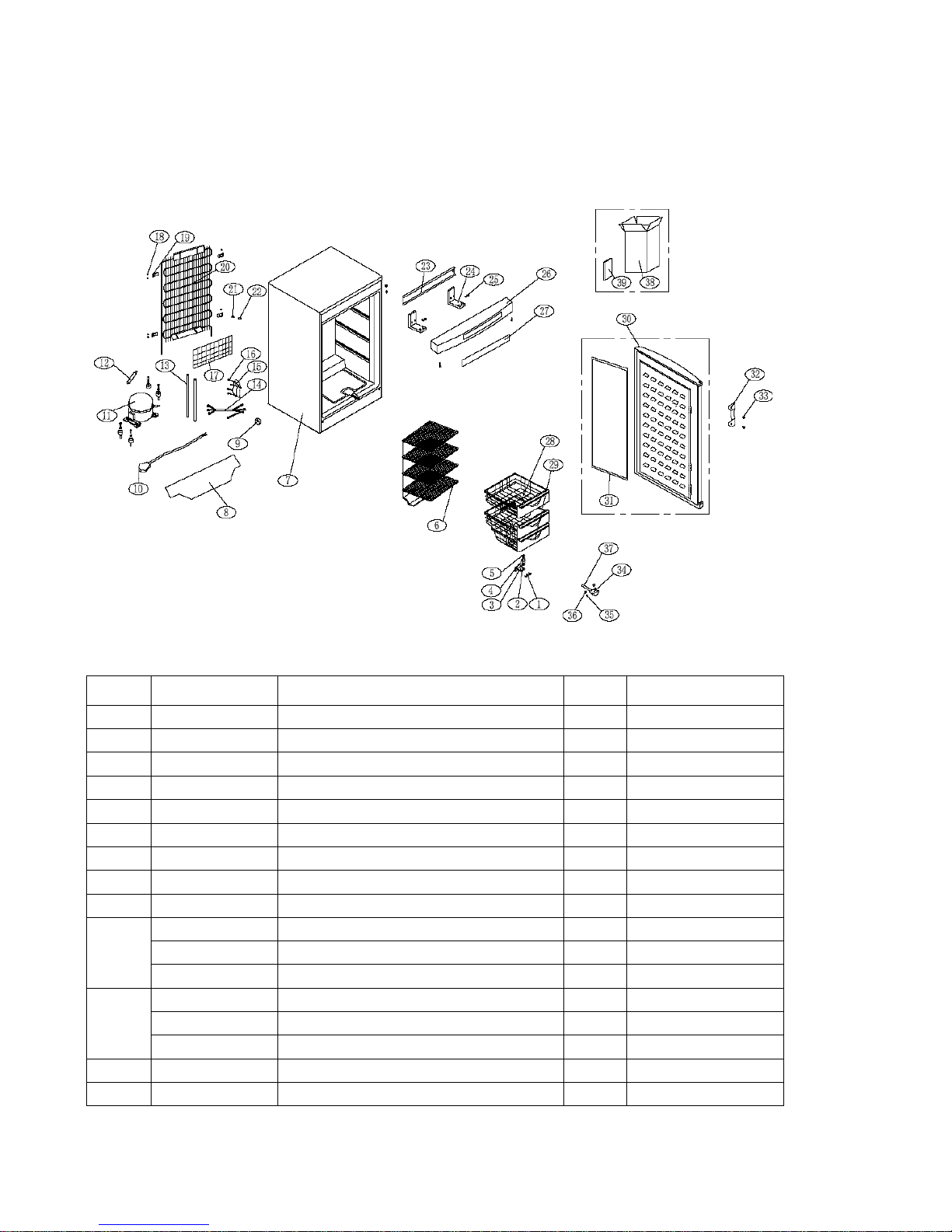
【Used Spare Parts Photo Gallery】
DW-25/40L262/300 Exploded view
DW-25/40L262/300 spare part list
No.
Code
Name
Qty
1
0060802007
Screw 15M6*16
3
2 0060100278
Seat of lower hinge Q215-A5mm
1
3 0064240002
Washer 65Mn
1
4 0067113077
Rotation shaft 15
1
5 0067744009
Washer PA white
1
6 0060201602
Right limit block PP
7
7 0070809547
DW-40L262 evaporator
1
8 0060201601
Left limit block PP
7
9 0060809575
Main foaming cabinet
1
10
0070104307
Fix board of compressor
1
11
0072130028
clips
2
12
0070400325D
EURO power cable
1
0270400113
British three pin power cable
1
0070401590A
British three column power cable
1
0070402229
American power cable1
1
220-240V/50Hz/60Hz
0070402228
American power cable2
115V/60Hz
13
0060700668
Compressor ZBC1115CY
1
DW-25L

30 / 33
0075010051
Compressor
SC12CL(220-240V/50Hz)
DW-40L
0274000190
Compressor
SC12CLX.2(220-240V/50Hz/60Hz)
1
DW-40L
0074091173
Compressor
SC12CLX.2(115/60Hz)
1
DW-40L
14
0070701909
DW-40L262 drier filter
1
15
0070401698
Compressor wire
1
16
0072040045
Wire connection box
1
17
0077050051
Screw
4
18
0070107165
Cover of cabin
1
19
0073150003
ROHS-sealing tube(black)490MM
4
20
0077050051
Screw
8
21
0067412381
built-in fitting parts PP
4
22
0060502027
Condenser
1
23
0067266077
ROHS-pipe inner suit PVC
2
24
0060211012
ROHS-sealing cover of Power cable
1
25
00601330269
Support board
1
26
0060812716
ROHS-upper hinge board
2
27
0064082716
Screw
4
28
0070809344
Display panel assy
1
29
0070506514
Display film
1
30
00601600103
Decorative strip of condensor
7
31
0270200215
Washer of evaporator
12
32
0270200562
Big door
6
33
0270200563
Small door
1
34
/ / /
/
35
0270800221
Foaming door
1
36
0070203433A
Door seal
1
37
0070107470
DW-40L262 handle
1
38
0077050001
Screw
2
39
0067412230
ROHS-drain box
1
40
0077050051
ROHS-screw
2
41
0067412233
Screw hat PE
2
42
0067412140
Drain pipe
1
43
0060211896
Shaft of defrost
1
44
0270500040
DW-40L262protect packing
2
45
0270500395
packing
1
46
0074091509
Condenser fan
1
DW-40L
31 / 33
DW-25/40L92exploded view
DW-25L92spare part list
No.
Code
Name
Qty
1
0060802007
Screw 15M6*16
3
2 00609380634
Seat of lower hinge
1
3 0064240002
Washer 65Mn
1
4 0067113077
Rotation shaft 15
2
5 0067744009
Washer of hinge
2
6 0270700332
Evaporator
1
7 0060809635
Foaming cabinet
1
8 0070104306
Fix board of compressor
1
9 0072130028
clips
2
10
0060611001
Power cable cn
1
0070400325D
Euro power cable
1
0270400113
British 3-pinpower cable
1
11
0060700668
Compressor ZBC1115CY
1
DW-25L
0074000149
Compressor NL7CLX
1
DW-40L
0075010051
Compressor SC12CL
1
DW-40L
12
0070701909
DW-40L262drier filter
1
13
0073150003
Seal pipe(black)490MM
2

32 / 33
14
0070401698
DW-40L188 compressor wire RVV3
×0.75
1
15
0072040045
Wire connect box
1
16
0077050051
Screw
4
17
0070107165
Cover of cabin
1
18
0060801078
Screw 15B3.5*9.5
8
19
0067412381
Built-in fitting of condenser PP
4
20
00605020261
Condenser
1
21
0067266077
Inner pipe suit PVC
2
22
0060211012
Seal of power cable
1
23
0060106846
Support board
1
24
0060812716
Upper hinge 188/368
2
25
0064082716
Screw
6
26
0070809343
DW-40L188 display panel
1
27
0070506515
Display film
1
28
0060211132
Drawer I
2
29
0060212152
Drawer II
1
30
0070810979
Foaming door
1
31
0270200177
Door seal
1
32
00601600095
DW-40L262 handle
1
33
0077050001
Screw
2
34
0067412230
ROHS-drain box
1
35
0077050051
ROHS-screw
2
36
0067412233
Screw hat PE
2
37
0067412140
Drain pipe
1
38
0070504995
DW-40L262protect packing
1
39
0060219168
packing
1
40
0074091509
Condenser fan
1
DW-40L

33 / 33
Inspired living
Haier Medical & Laboratory Products Co., Ltd.
Room 403D, Brand Building, Haier Industrial Park, No.1 Haier Road
Qingdao China
Website: www.haiermedical.com
 Loading...