

Air Cooled Module Water Chiller
Installation, operation and technical manual
Heat pump / Cooling only
R22 refrigerant
100KW
Haier Commercial Air Conditioning
3PH, 380V, 50Hz
MANUAL CODE: SYJS-035-06REV.2 2008-04-30

HAIER CHILLER
2
TABLE OF CONTENTS
1. Nomenclature……………………………………………………………………………………………………..3
2. Product character…………………………………………………………………………………………………3
3. Specifications……………………………………………………………………………………………………..5
4. Dimension data…………………………………………………………………………………………………...7
5. Installation and debugging………………………………………………………………………………………8
Water system installation diagram…………………………………………………………………………….11
9.
6. Refrigerant circuit……………………………………………………………………………………………….10
7.
Auxiliary electric heating function control. ……………………………………………………………………14
10. Water pump operation control(valid when water pump and the unit controlled simultaneously)……….14
11. The terminal simultaneous control…………………………………………………………………………….15
12. Wired controller functions………………………………………………………………………………………16
14. Maintenance………………………………………………………………………………………….........…....34
8. Wiring diagrams………………………………………………………………………………………………....13
14. Control functions………………………………………………………………………………….........…........28
HAIER CHILLER
3
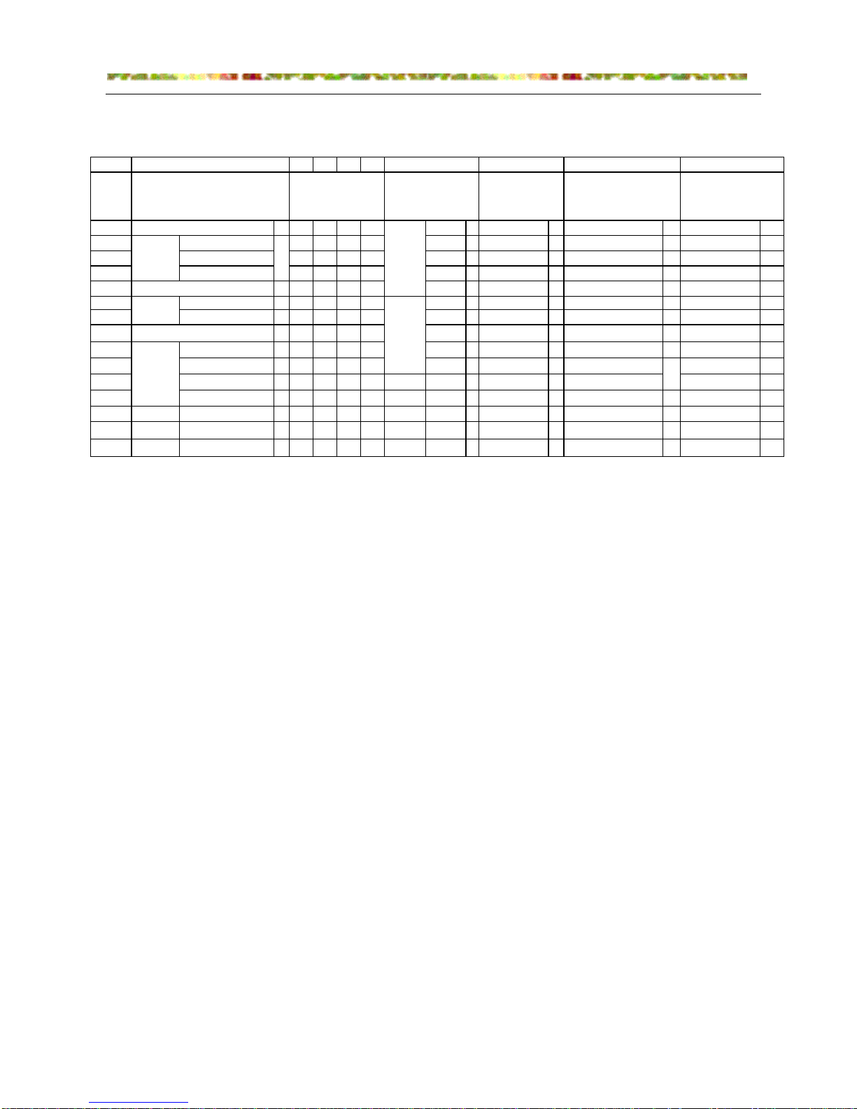
1. Nomenclature
2. Product character
a. Installation conveniently, no need the special machine room and water tower; can be installed on the
roof or out of the room. Widely application for cinema, hospital, hotel, school, commercial building, etc.
b. Utilize flexible scroll compressor. And adopts three compressors in parallel technology. The master unit
will control all compressors run or stop due to the water outlet temp. Optimum refrigerant distribution
technique and minimum-deformation design. Adoption of rolling bearing and non-lubricated bearing.
Excellent heating effect at low temperature. Broad range of working temperature and suitability for high
condensation temperature.
c. Shell & Tube and U type inner grooved finned coil heat exchanger.
High efficient water side heat exchanger: in cooling, the water side heat exchanger is as evaporator; in
heating, it is as condenser. The freezed water flows outside of the pipe, and the refrigerant flows in the
pipe. Optimum design, reliable operation, reasonable structure, perfect performance.
d. Central control technology, indoor unit be connected with controller by dual core non-polar wire. The
indoor units can be controlled individually or simultaneously, more convenient, more energy saving.
One central air conditioning system can include max. 16 sets of module unit. Through the dip switch on
PCB you can set unit No. of every module unit, and every unit is connected by RS485 port. Compact
1 3456
chiller
system
C
C
1069 R22 Aair cooled A
100-115V, 60Hz 1
fixed frequency A-G
air cooled 0237 R407C B water cooled W
220-240V, 50Hz 2
inverter H-Q
water cooled 0 0 1 2 R132 C earth source E
115-220V, 50/60Hz 3
DC inverter R-Z
earth source R134a D
220-220V, 60Hz 4
A
R410a E
110V, 50-60Hz 5
H
R22 M
220V, 50-60H
z
6
R
R407C N
127V, 60Hz 7
W
R123 O
240V, 50Hz 8
Cassatte
B
R134a P
110-220V, 50/60Hz 9
Duct
D
R410a Q 330V, 50Hz A
Cabinet
P
400V, 50Hz B
Wall mounted
S
3300V, 50Hz
C
6600V, 50Hz D
380-400V, 50Hz N
415V, 50Hz M
Code Explanation for chiller
compressor type
capacity (for
Centrifugal chiller:
Rt; other: KW)
product type unit character
2
7
89
heat
pump
cooling
only
10
Air-cooled module chiller
suitable voltage design number
Light
chiller
Water-cooled cabinet chiller
Hydronic
system
Centrifugal chiller
Screw
chiller
single-packaged
I
split-packaged
structure, convenient for electric installation.
e. Fan coil simultaneous control technology: indoor fan coil can be controlled individually or centrally.
Every indoor unit is connected to the individual controller or central controller through dual-core
non-polar wire to realize the cental control. When one indoor starts up, the central air conditioning

HAIER CHILLER
4
system will start up automatically. When all indoors arrive the set temperature, the master unit will stop.
Energy saving.
f. Auto check technology: The system can check the operation status automatically; all kinds of sensors
will transmit the operation parameters to the chip. By pressing the buttons, all the parameters can
display on the liquid crystal screen. When the unit occurs failure in operation, the failure will display on
the LED so that the malfunction can be solved soon.
g. Password control function: According to the user setting, the password control function can be used.
Therefore the control to the unit will be more reliable and more flexible.
h. Equipped with RS-485 physical connector, perfect network communication ability.
i. Module structure design, the system can be produced or transported as module unit. Every system is
independent, and they are spare part for each other, however which cooling circuit is abnormal, the
other systems do not be affected by the abnormal system, and furthermore they will run in shape.
Module structure can reduce the cost of transport and installation greatly, more convenient.
j. Heat exchanger of air side is designed much larger, enlarge heat transmission area, lower the
temperature drop of transmission. Consequently, the chiller can run in cool mode even at high
temperature of 45celsius degree in summer, and also can run in heat mode at low ambient temperature
of –15celcius degree in winter with good performance.
k.
Safety and protection devices: phase reverse protection device, high and low pressure switch, freeze
protection device, overheat protection device, overload protection device, etc. Also, with Timer ON/OFF,
AUTO operation, defrosting, etc. functions.
HAIER CHILLER
5
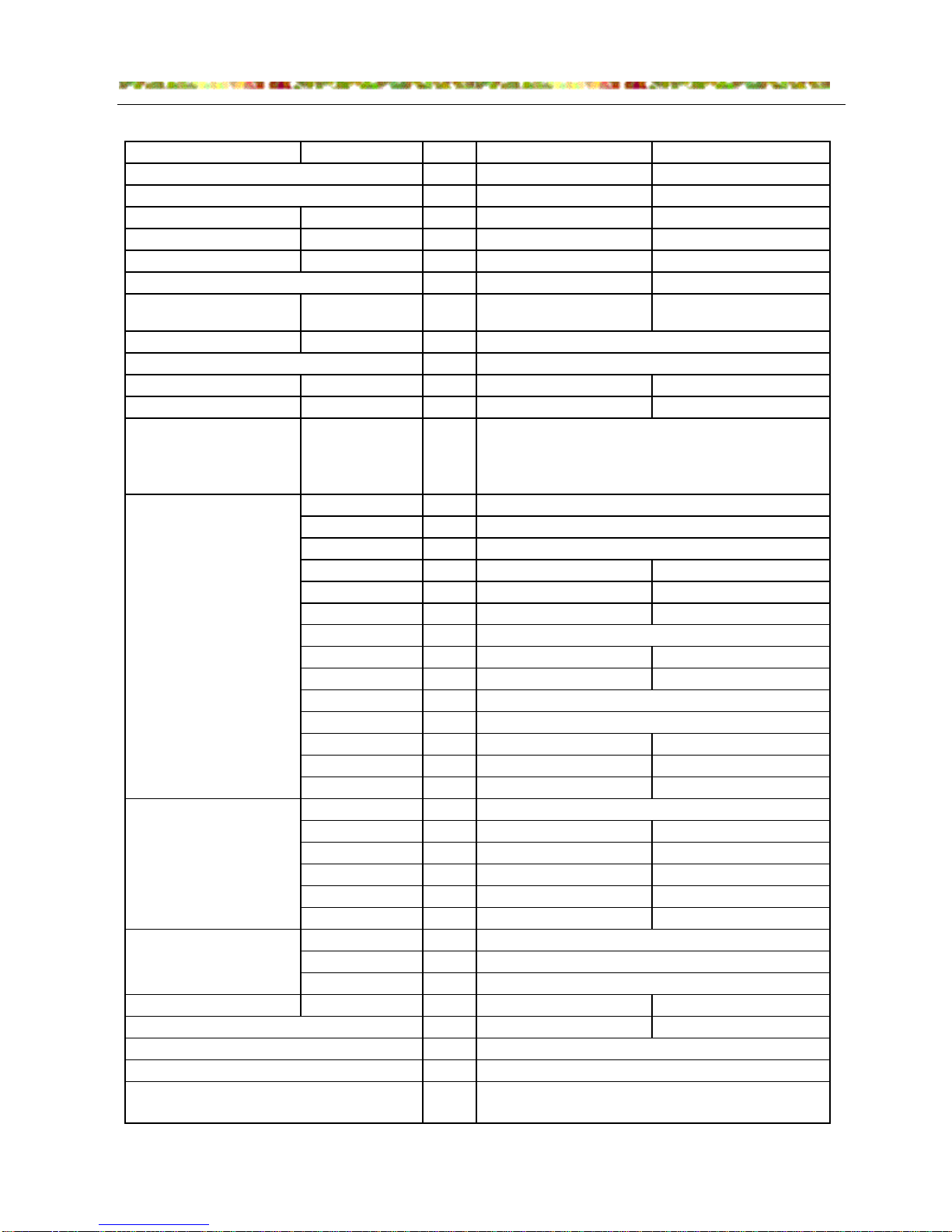
3. Specifications
Model CA0100MANB CA0100AANB
KW 98 98
KW / 105
Total power input KW
Start current A 164 164
Running current A 21 21
A 67.5 67.5
Recommended circuit
breaker
A
GV2-M22C(23A)/GV2-
M16C(10)
GV2-M22C(23A)/GV2-
M16C(10)
Power supply
Appearance colour Haier gray Haier gray
Capacity control step 3 3
Safety&functional
protection
model
type/manufacture
COP
quantity set 3 3
power input KW 9.98Kw 9.98Kw
rated power KW 10.1*3 10.1*3
power supply
running current A 17 17
starting current A
159A(380V,50Hz) 159A(380V,50Hz)
oil type
oil charge ml
crankcase heater W 72 72
weight kg 71 71
rated speed rpm 2900 2900
type
quantity set 3 3
rated power KW 0.75*3 0.75*3
running current A 2.5 2.5
Air flow m3/h
Fan speed rpm
length mm
width mm
height mm
Refrigerant charge(R22) kg 30 30
Refrigeration system (circuit quantity) 3 3
Refrigeration control method
Nominal cooling capacity
Nominal heating capacity
Max. running current (in the electric control box)
Running control method
3PH, 380V, 50Hz
fully automation
axial flow
Air side heat exchanger
Fan
External dimension
Water side heat exchager
water-lackage delay protection,high and low pressure
switch, freeze protection device, overheat protection
device, overload protection device, phase loss &
sequence protection
JT335D-Y1L
shell & tube heat exchanger, working pressure 1.0MPa
Compressor
2635
1350
2136
SUNISO4GSDID-K
3000
cross finned coil, inner grooved copper pipe&dydrophilic
aluminum finned coil
hermetic scroll / DAIKIN
3.41
3PH, 50Hz
thermostatic expansion valve
32.25 32.25
9000*3 9000*3
960 960

HAIER CHILLER
6
Water flow m3/h 18 18
Water resistance kPa 50 50
mm 65 65
Noise level DB/(A) 66 66
Net weight kg 1100 1100
Running weight kg 1150 1150
Casing
The noise level will be measured in the third octave band limited values, using a Real Time Analyser calibrated
sound intensity meter. The noise level is measured at 2meter in front of the unit, 1.5 meter high to the ground.
When starting up the complete unit, the compressor will start up one by one and will not start up together.
The permitted range of voltage is 380±10%
Nominal working condition (cooling ):water inlet temp. 1
2
℃, water outlet temp. 7℃, ambient temp. 35℃。
Nominal working condition (heating ):water inlet temp. 40℃, water outlet temp. 45 ℃, ambient temp. (DB)7℃,
(WB)
6℃
Water pipe diameter
polyester painted galvanized steel plate, Haier gray
HKZSKLUO MXWNS\SXW MXXUSWQ MKYKMS\a + SWY]\ YX_OZ MXZZOM\ M]Z^O
@WY]\ YX_OZ ,A_-
<VLSOW\ \OVY0 ,l-
>XXUSWQ MKYKMS\a ,AI-
IK\OZ X]\UO\ \OVY0 ,l-
241
231
216
:1
86
5204
4904
4603
4302
3:02
<VLSOW\ \OVY0
<VLSOW\ \OVY0
dfc
dec
dch
kc
jh
ic
fibj
ffbj
fcbi
ejbh
egbh
HKZSKLUO MXWNS\SXW ROK\SWQ MKYKMS\a + SWY]\ YX_OZ MXZZOM\ M]Z^O
<VLSOW\ \OVY0 ,l-
?OK\
SWQ MKYKMS\a ,AI-
@WY]\ YX_OZ ,A_-
IK\OZ X]\UO\ \OVY0 ,l-
<VLSOW\ \OVY0
<VLSOW\ \OVY0
HAIER CHILLER
7
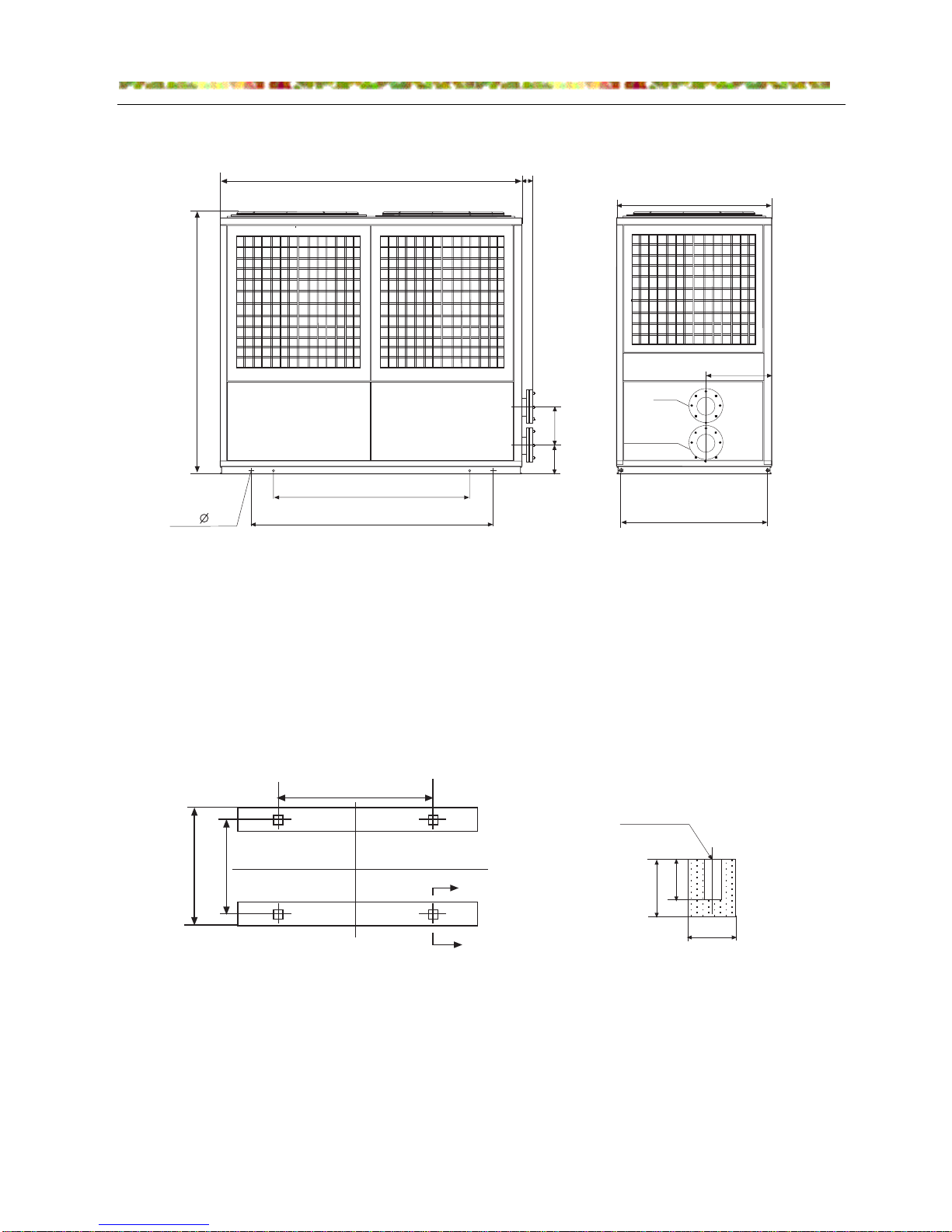
4. Dimension data
4.1 Installation dimension
4.2 Foundation dimension
4.2.1 The bearing capacity of the foundation shall be designed according to the unit's operation weight.
4.2.2 The foundation can be beam channel (designed by the installer according to the unit outline
dimension) or concrete structure, and the surface of the foundation shall be flat.
4.2.3 A 10~20mm rubber anti-vibration cushion shall be used between unit and foundation.
4.2.4 The unit can be fixed on the foundation by using anchor bolt with 16 or 18mm diameter.
2711 +?JNOCIIHJF >KIE,
2491+>KHNOHJF >KIE,
5- 29
ACOEM HJIEO
ACOEM @POIEO
=KPJDCOHKJ
?JNOCIIHJF >KIE
2520
115
2136
258
303
1290
475
1350
2711
?
?
?/? QHER;
LMENEO GKIE
211B211
461
311
361
1540
1290
HAIER CHILLER
8
5. Installation and debugging
5.1 Freight Check
All the units are tightly fastened on the wooden pallet by the bolts. Before leaving factory, the units
are all checked and pre-filled with refrigerant and refrigerant oil, both of which are the precise amount
the unit operation needs.
When user receives the product, he shall check it carefully to confirm if there is product damage in
transportation and to confirm all the pre-ordered parts are received. If there is any damage, he shall
immediately inform the transportation person and claim for compensation according to relevant clauses.
If there is problem except for surface damage, he shall immediately inform our company.
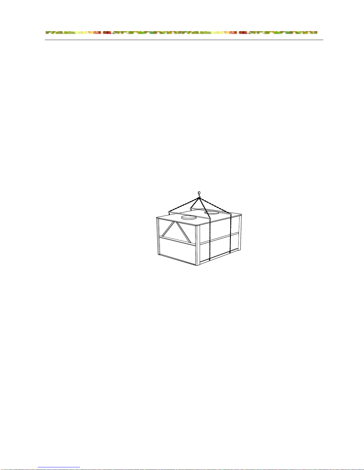
5.2 Transportation
In order to be convenient to carry the unit, the user shall use forklift or crane. When using crane,
there shall be proper partition to protect the top and side panel of the unit (as Figure shown). During
carrying, the unit shall be kept level, and the gradient shall not exceed 30°. Try to avoid units damage
due to improper operation.
5.3 Unwrap the packaging
After putting the unit on the site, cut the packing strap and remove the outer crate. Unscrew the
tightening bolt and remove the wood pallet from the bottom of the unit.
5.4 Selection of Installation Place
5.4.1 The installation place shall be plane, the foundation surface shall be flat, and the supporting surface
can bear the operating weight of the unit.
5.4.2 The unit shall not be installed in a place where there is too much dust, corrosive gas, high humidity or
insects gathers easily, fallen leaves and other contaminative matters.
5.4.3 Recommend that maintemance space among units should be over 400mm.
5.4.4 There shall be over 1.5m space around the unit to be convenient for ventilation and maintenance.
5.4.5 Try to keep the unit away from sunshine and rain, it is recommended to cover the unit with shed, but
be sure there is a space over 3m above the air outlet for releasing heat easily.
5.4.6 An anti-vibration cushion about 10-20mm shall be equipped between the unit and the foundation.
After adjusting level, fasten the anchor bolt.
5.4.7 For the heat pump unit, there shall be a drain for the condensate.

HAIER CHILLER
9
5.4.8 The installation and thermal insulation of the water pipes of the air conditioning system shall be
designed and instructed by the professionals and shall implement the relevant regulations of the Installation
Standard for HV & AC.
5.4.9 The external water pipe system must be equipped with anti-vibration hose, water filter, electronic
water cleaner, check valve, drain valve, discharging valve, stop valve and expansion tank, etc. The
expansion tank shall be installed 1-1.5m higher than the system top, and its capacity is about 1/10 of the
total water amount of the system. The air release valve shall be installed between the top of the system and
the expansion tank, and the water tank and the pipe shall be thermal insulated.
5.4.10 The water supply system must match the water pump with proper water flow and proper head to
ensure the supply for the unit normally.
5.4.11 The unit must be equipped with a water filter in front of the water inlet pipe and use the mesh with
16~40-mesh filter.
5.4.12 The anti-vibration hose must be used between water pump and unit, between water pump and water
pipe of system. At the same time, the pipes and the water pump shall have bracket to prevent the unit from
receiving force.
5.4.13 Wash and thermal insulation of system water pipes shall be done before connecting the pipe with the unit.
5.5 Safety Precautions
5.5.1The system pressure and electric parts will cause danger to the installation and maintenance of the air
conditioner, so only the authorized personnel with qualification can perform the installation, operation and
maintenance of the air conditioner.
5.5.2Please comply with the protection measures and safety warnings marked on the documents, labels
and nameplate on the unit.
5.5.3 Please comply with various safety regulations, wearing safety glasses and working gloves, and when
welding, wear the fireproof clothes.
Warning: Before maintaining the unit, cut off the main power supply of the unit,
otherwise electric shock will cause.
5.5.4 When maintaining, only the original parts shall be used and pay attention to correct installation, and
the parts must be installed in their original position.
5.5.5 During unit operation, the temperature of some parts of the refrigerant circuit may exceed 70℃, so
that the untrained personnel shall not make bold to remove the protection panel of the unit.
5.5.6 Unit shall not be installed in the air containing explosive gases.
5.5.7 If the heat pump type unit operates under the condition below 0℃, it must be installed in a place
300mm higher than the ground, which can not only prevent the bottom plate from freezing, but also prevent
the accumulated snow from reaching this height to influence the unit's normal operation. The unit shall be
installed on a flat surface (the max. deviation of the ground level shall not exceed 2mm/m.)
HAIER CHILLER
10
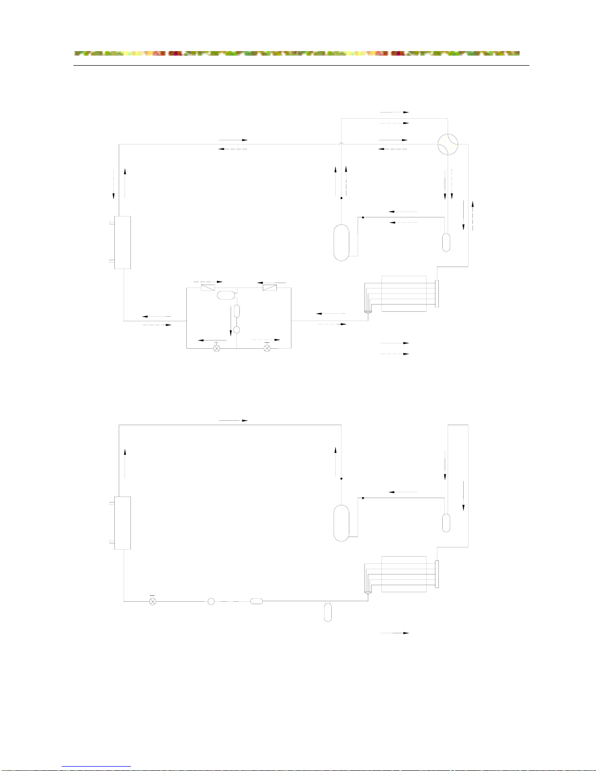
water
side
heat
exchanger
thermostatic
expansion valve
liquid side
glass
filter drier
one way
valve
accumulator
water
inlet
hole
Cooling
Heating
Cooling
water
outlet
hole
air side heat
exchanger
compressor
gas-liquid
segregater
four-way
valve
water
outlet
hole
water
inlet
hole
water
side
heat
exchanger
air side heat
exchanger
gas-liquid
segregater
compressor
thermostatic
expansion valve
liquid side
glass
filter drier
accumulator
CA0100AANB
CA0100MANB
6. Refrigerant circuit

HAIER CHILLER
11
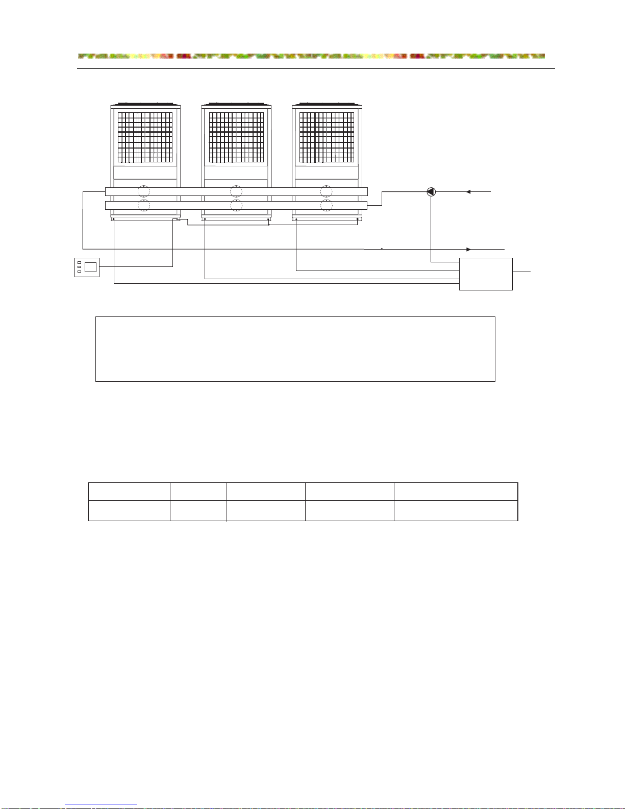
7. Water system installation diagram
6@=B8 D=D9
,CG9v
mj }@9K=6@9 <CF9 >C=BG nj .E9FFHE9 ;5H;9
oj 1CG5@ J5G9E E9GHEB F9BFCE =BFG5@@ D@579 pj 1<9EACA9G9E
qk mmk mqj 0GCD I5@I9 rj yLjD5FF I5@I9
sj -B9jJ5L I5@I9 tj }@9K=6@9 >C=BG
uj 35G9E .HAD mlj 35G9E FGE5=B9E
mnj 9@97GE=75@ J5G9E DEC79FFCE moj xHGC 8=F7<5E;=B; 5=E I5@I9 g<=;<9FG =B G<9 J5G9E FLFG9Ah
mpj |KD5BF=CB J5G9E G5B? mrj {E5=B I5@I9
J5G9E =B@9G
J5G9E
CHG@9G
8E5=B5;9
<C@9
CI9E:@CJ <C@9
mp
mo
mmmnmmmlmnu
msrq
pn
n
p
m
o
m
mr mq
19EA=B5@
rl
ml
69GJ99B pq jmoq
q
J5G9E FHDD@L
<C@9
3<9B 7=E7H@5G=CB J5G9E EHBF :CE G<9 :=EFG G=A9i 7@CF9 G<9 =B@9G 5B8 CHG@9G I5@I9 g,Ckqh5B8 CD9B G<9 6LjD5FF
I5@I9 g,Ckrhk 3<9B J5G9E DHAD JCE?F :CE 5 J<=@9i 7@95B G<9 J5G9E :=@G9E F7E99Bk 3<=@9 9BFHE=B; G<5G G<9E9 =F
BC =ADHE=GL =B G<9 9KG9EB5@ 7=E7H@5G=CB FLFG9Ai CD9B =B@9G 5B8 CHG@9G I5@I9 g,Ckqh5B8 7@CF9 G<9 6LjD5FF I5@I9
g,Ckrhk 1<9Bi G<9 HB=G =F =B BCEA5@ CD9E5G=CBk
,CG9v
J<9B G<9 =BFG5@@5G=CB =F CI9Ei G<9 GCG5@ J5G9E CHG@9G G9AD9E5GHE9 F9BFCE =B G<9 A5=B AC8H@9 AHFG 69 :=K98 CB
G<9 ;9B9E5@ J5G9E CHG@9G D=D9@=B9k .5L 5GG9BG=CB G<5G 5 F97G=CB C: 6@=B8 D=D9 gNti *wrlAAh 69 E9F9EI98 :CE
G<9 =BFG5@@5G=CB C: G9AD9E5GHE9 F9BFCE 8HE=B; F=G9 89F=;B 5B8 G<5G G<9 =BF9EG @9B;G< C: 6@=B8 D=D9 =F qlAAk
3<9B =BFG5@@=B; G<9 F9BFCEi D@579 G<9 F9BFCE 69B95G< G<9 6@=B8 D=D9 5B8 =B>97G FCA9 E9:E=;9EBGB C=@ =BGC G<9
6@=B8 D=D9k 1<9 @9I9@ C: G<9 E9:E=;9E5G=CB C=@ F<CH@8 69 5G @95FG mlAA CI9E G<9 F9BFCEk 1C A=B=A=M9 <95G GE5BF:9E
9EECEi =G =F B979FF5EL GC 58CDG G<9EA5@ =BFH@5G=CB A95FHE9Fk
35G9E 0LFG9A ~BFG5@@5G=CB {=5;E5A
{=5;E5A C: J5G9E D=D9 7CBB97G=CB 69GJ99B G<E99 HB=GF
HAIER CHILLER
12
CX\O;
1. The connecting wire of the unit only refer to the power wire for power supply and communication
control wire. The control wire in the electric box attached with the unit had been connected properly
before they left factroy, the user shall not change by themselves.
2. The working currents of the unit are shown in the following table, when wiring, it must to ensure the
unit can work normally.
1LD=75@ 3=E=B; 5B8 .=D9 zCBB97G=CB
+5FG9E +C8H@9
0@5I9jAC8H@9
35G9E ~B@9G
35G9E -HG@9G
.CJ9E
{=FGE=6HG=CB
yCK
3=E98 zCBGEC@@9E
0@5I9jAC8H@9
o
m
n
p
q
m
m
n
,CG9v
mk 2B=G .CJ9E 0HDD@L zCE8 pk 35G9E .HAD .CJ9E zCE8
nk +C8H@9j65F98 2B=G zCAAHB=75G=CB 3=E9 qk z56@9 GC 2B=G .CJ9E {=FGE=6HG=CB yCK
ok 2B=G -D9E5G=CB zCBGEC@@9E 3=E=B;
q4nqAA
n
gmolKohxrskqxqnkqx
/5G9 zHEE9BG +5K=AHA zHEE9BG *C7?98jECGCE zHEE9BG
/9:9E9B79 z56@9 097G=CB5@ xE95
2B=G +C89@
zxlmllxx,y
zxlmll+x,y

HAIER CHILLER
13
8. Wiring diagrams
a. The unit wiring diagram

HAIER CHILLER
0010452203 for CA0100AANB
K1
K2
K3
K4
K5
K6
K7
K8
K9
U1
U13
U2
U3
U4
U5
U6
U7
U8
U9
U10
U11
U12
14

HAIER CHILLER
15
b. The driving wiring diagram
c. The communication wiring diagram
9. Auxiliary electric heating function control
The auxiliary electric heating function will be performed in low ambient temperature. Connect the water
inlet/outlet pipe with auxiliary electric heater to the total water inlet/outlet pipe, in the electric control box of
the master module, there is the control port of auxiliary electric heating (only with 220V output, not supply
the electric heating control part).
10. Water pump operation control (valid when water pump and the unit controlled
simultaneously)
In the electric control box, there is the freezed water pump simultaneous control port (only with 220V
output, not supply the water pump control part). When the unit is in standby state, water pump will not start
up; when the unit enters working state from standby state, start up water pump firstly; when the unit enters
standby state from working state or stop state, 30seconds later, water pump will stop automatically. In stop
state, when water outlet temp. is no more than 3 degree and more than 2 degree, the water pump will start
up; when water outlet temp. is no more than 2 degree, start up one module in heating and stop until water
temp. arrives 8 degree.
slave
unit 15
slave
unit 1
master
circuit
breaker
circuit
breaker
circuit
breaker
12V
GND
A
A
B
GND
CN102A COMM
No.n slave
unit PCB
B
A
B
…
12V
B
GND
GND
A
No.1 slave
unit PCB
CN102A C OMM
A
B
B
A
12V
GND
main unit PCB
CN102A COMM
GND
MCU

HAIER CHILLER
16
11. The terminal simultaneous control
Connect the passive port of the terminal controller to the simultaneous control port in the controller of
the master module unit. When the unit is running and the controller is in simultaneous control state, when
one of terminal unit starts up, the chiller system will start up automatically. When all the terminal units stop,
the chiller system will stop later.
When in electric wiring, please pay attention to the following:
a. The wires are the power supply cable and the communication wire. The wires with the unit have been
fixed properly, and should not be modified by the user. Use four-core shield wire when install the
communication wire and earth one end of the shield layer. Do not put the communication wire and
high voltage wire together, or the communication error will occur.
b. The unit running current is as below table:
model Rated current Max. current Rocked current
Cable section for
reference
CA0100* 52.5A 67.5A (130*3)A 5*24mm
2

HAIER CHILLER
17
12. Wired controller functions
?Yb_[Qg bSaUU];
JQ]U[ TYb_[Qg
G^TU TYb_[Qg
>[^SZ TYb_[Qg
X^da \Y]dcU
MY\Ua bUccY]W TYb_[Qg
OXU] cXU Q__[YQ]SU Yb Y] bUQaSX ^a bUccY]W \^TU
Q]T cY\U _QaQ\UcUa ^_UaQcY^]- cXYb h^]U TYb_[Qgb
\^TU Q]T cY\U _QaQ\UcUa/
C
LG
>^TU TYb_[Qg
JQaQ\UcUa.bUccY]W Y]TYSQcY^]
AQd[c S^TU Y]TYSQcY^]
JQaQ\UcUa 0 VQd[c S^TU
KUbc^aQR[U VQd[c S^TU Y]TYSQcY^]
LUaY^db VQd[c Y]TYSQcY^]
MU\_UaQcdaU TYb_[Qg
C
LG
MY\U.bUccY]W TYb_[Qg
N]Yc ]d\RUa TYb_[QgY]W h^]U
EUg_QT ^V fYaUT S^]ca^[[Ua
MDG@K
>F>IE
MDG@ M@GJ
C@<M@K
GI?@
K@L@M
Idc_dc U`dY_\U]c TYb_[Qg
IJMDIHL
fQcUa _d\_
[^SZ
XUQcUa
5.fQg
eQ[eU
TUVa^bc
S^\_aUbb^a
^dcUa
VQ]
2
3
4
S^^[Y]W
XUQcY]W
6
7
3
6
9
5
2
7
4
8
5
8
9

HAIER CHILLER
18
Controller system is constituted by 1 to 16 HAC-F3S-H PCB and one or many MCU. parallel connect
each MCU when use many MCU.
There should be at least one main module PCB in the system, the address of which is 0000 and the No.
is 1#. From the module PCB can connect max. 15 and address can be setted from 0001 to 1111, set No.
from 2# to 15#. Each PCB must be setted address differently in the system.
Setting method of module number
1. Press the DOWN, M and T button.
2. Input the password (0000) to come into the program.
3. Press S button after you input four zero.
4. The LED will display six code(A, B, C, D, E, F). They stand for six kind of data.
A --- unfreeze data
B --- work temp
C --- protect
D --- work data
E --- password setting
F --- number module setting
5. Press UP or DOWN to choose F and S to confirm it.
6. You will see an “A” symbol.
7. Press DOWN button, “B” will be added. And repeat press DOWN, “C” will be added. Repeat this
process till A B C D E F displayed.
8. Press M button twice to quit the program.
9. The LED will display “---” after you quit the program and last 26 seconds or so. The program is
resetting during this period.
10. Start the chiller according to normal process
12.1 Operation and guidance
There are 11 Touch buttons on the control panel for On/Off operation, mode selection, parameter query,
Module PCB
(1#)
Module PCB
r(2#)
Module PCB
r(3#)
MCU
RS485
Module PCB
(4#)
Module PCB
(16#)

HAIER CHILLER
19
temperature setting, clock setting, timer setting, reset/dark. General layout of all touch buttons is illustrated
in the above diagram. Press valid button once or receive signal by remote control, LCD will display the
corresponding mode, backlight lightens, the buzzer gives a beep, and backlight is off 10 seconds later
automatically.
12.2 Control functions
1. Working mode: cooling → heating
2. Working method: auto running operation
3. Monitor type: real time monitoring (resumable fault, serious fault protection): query display (real
time temperature detection)
4. Intelligent operation when a sensor fault occurs.
5. LCD backlight (yellow/green light, blue light, white light)
6. Fault alarm
7. Remote receiving function (informed before being ordered)
8. Resumable fault protection
9. Serious fault protection.
12.3 Buttons operation instructions
12.3.1 Clock adjustment
Press [CLOCK] into the clock adjustment. Firstly the minute indicator flashes, which shows that you
can adjust clock by pressing [▲] and [▼] keys. Press [▲] once, the number is increased by 1, press time
key [▼] once, the number is decreased by 1. If pressing time [▲] and [▼] keys for a long time, the number
will increase and decrease automatically.
Press [CLOCK] again in the minute setting mode to enter hour setting mode.
Time adjustment can be cycled by pressing [CLOCK] key. If the controller is not operated within a fixed
period of time, it will quit time adjustment automatically.
12.3.2 Timer setting
Press [TIMER] to enter timer setting. Timer setting sequence is as follows: minute setting of TIMER ON,
hour setting of TIMER ON, minute setting of TIMER OFF, hour setting of TIMER OFF,
repeating/combination timer setting, cancellation of timer setting.
In the timer setting mode, the adjustment of [▲] and [▼] keys is as the same as clock adjustment.
12.3.3 On/Off operation
When unit is off, red indicator of controller lightens. Start up the unit by pressing [On/Off].
When unit is on, green indicator of controller lightens. Stop the unit by pressing [On/Off].
Caution: if the controller is used to set the interlink function of the indoor fan coil and the controller
receives no interlink signal, green indicator of controller will lighten when the appliance is working. If serious
faults are present, red indicator of controller will lighten.

HAIER CHILLER
20
12.3.4 Mode setting.
Press [MODE] to enter the mode setting. Controller recognizes controller mode automatically. Mode
setting cycles between cooling and heating.
12.3.5 Temperature-setting
When the unit is on, you can adjust controller to set temperature. Press the [▲] and [▼] keys, the
temperature will increase and decrease accordingly. The max and min temperature values are determined
by controller.
12.3.6 Fault query
When a fault occurs, symbol of “unit” glistens and also fault code displays in the fault code displaying
zone. Corresponding unit number also glistens at the interval of 2 seconds, press [query] key will display
fault code in the fault code displaying zone.
If there are several faults, press [▲] and [▼] key, you can see fault codes in turns.
12.3.7 Temperature query
Press the [QUERY] key, you can check temperatures and unit state. On normal condition, unit number
represents the running unit. Press the [QUERY] key, you can chose unit number that is activated, and the
chosen unit number glistens quickly at the intervals of 0.5 second.
When the unit is in query mode, press time key [▲] and [▼], you can see fault code in turn. Press
temperature key [▲] and [▼], you can see the temperatures of all units.
When the unit temperature is in query mode, the code of sensor from P01 to P08 is shown on the code
displaying zone, temperature displaying zone presents the corresponding temperature. The sensor that is
not equipped to the controller will not be displayed.
12.3.8 Output equipments status query
When the unit is in query mode, equipment output status will be shown on the controller.
12.4 Functions descriptions
12.4.1 System structure
A. single unit system
B. Multi units system: integrating an outdoor unit and several indoor units into a centralized controlling
system by RS-485 bus. The multi system use one water system; the outdoor unit controls interlinked
operation of system pump and other indoor units use the same water system. The master unit
harmonizes the whole system, and the slave units are consistent with the master unit. When the
working mode of the master unit changes, all slave units change accordingly. When the master unit is
off, all slave units can’t be turned on.
12.4.2 Unit number setting
The system is a central air conditioner controlling system consisting of one wired controller and 16
modules numbered from 1 to 16. Every controller panel is assigned with a different address according to

HAIER CHILLER
21
the number of system modules used. There is a dip switch which includes 4-digit set on the controlling
panel, according to which we can set the module number of unit. After the communication between a
module and the wired controller is established, there is one lighting dot representing it on the wired
controller.
Diagram of module code number:
Switch 1 Switch 2 Switch 3 Switch 4 Controller No.
OFF OFF OFF OFF Outdoor unit
OFF OFF OFF ON Indoor unit 1
OFF OFF ON OFF Indoor unit 2
OFF OFF ON ON Indoor unit 3
OFF ON OFF OFF Indoor unit 4
OFF ON OFF ON Indoor unit 5
OFF ON ON OFF
Indoor unit 6
OFF ON ON ON Indoor unit 7
ON OFF OFF OFF Indoor unit 8
ON OFF OFF ON Indoor unit 9
ON OFF ON OFF Indoor unit 10
ON OFF ON ON Indoor unit 11
ON ON OFF OFF Indoor unit 12
ON ON OFF ON Indoor unit 13
ON ON ON OFF Indoor unit 14
ON ON ON ON Indoor unit 15
Dip switch (TYPE ADDRESS) used to set the unit type
12.4.3 Operation modes:
Cooling, heating
12.4.4 Control functions
a. Indoor fan coil interlink function
When setting the indoor fan interlink, control panel detects On/Off mode of the interlink switch at
anytime. When one or more indoor fan coils open, interlink switch closes, the system is operates. When all
the indoor fan coils close, interlink switch is disconnected for 30s, the system stop working now. When the
interlink switch of one indoor fan closes and the indoor fan has been off for at least 3 minutes, the system
will restart.
Switch 1 Switch 2 Function name Function specification
ON ON Cooling only Cooling Only mode
OFF OFF Heat pump +electric heat Cooling, heating, auxiliary electric
heating
Caution: Type must be set according to requirements.

HAIER CHILLER
22
b. Timer On/Off
Timer on, timer off, cycling timer setting and combination timer setting can be chosen through wired
controller. Each combination timer setting is valid for within 24 hours and cycling timer setting is valid all the
time. The combination timer setting can be selected only when the code [SA09] is set as Off, and the
cycling timer setting can be selected only when the code [SA09] is set On.
c. Temperature sensor compensation
In some special cases, if the sensor lead is too long or the installation of indoor fan is limited by
installing space, the measured temperature of sensor needs compensation and correction. This function
can be achieved by revising code [PC01] and [PC08]. If one code is set as cancelled “---”, it means the
respective temperature sensor is cancelled. Corresponding function and protection function will be
cancelled as well.
d. Unit power-off memory
e. Fault alarm and query
f. Return water temperature, environment temperature and coil pipe temperature display and query.
g. Unit operating code set and reset
h. System clock set and display
i. Compressor operating average energy consumption
The system records the operation time of every compressor separately, those with a shorter operation
time will start first when the system starts, and those with a longer time will close first when the system
closes.
j. Defrosting options
12.4.5 Protection and safety
a. Over-load protection for cooling operation
The outdoor coil temp. will rise if the cooling load too high, when the temperature is higher than [EP02],
over-load protection will be activated.
b. Over-temperature protection for heating operation
When the system is in the process of heating, in order to avoid fault of inner coil pipe due to
over-temperature, if the return water temperature is higher than [EP04], over-temperature protection will be
activated.
c. Frost-proof in winter
In order to avoid circulated water being frozen in the winter, controller will protect the system.according
to code [EP07]. Controller has 2-level frost-proof protection, the Level 1 protection starts the circulating
pump, auxiliary electric heating at a fixed intervals. The Level 2 protection starts the heating system of
compressor to heat the circulated water.
d. Flow protection switch

HAIER CHILLER
23
When the there is no or litter water flow in the pipe, the switch will cuts off control circuit to close the
unit, protect the unit and compressor.
e. Overload protection of compressor
There is a crankcase-heater and a thermal overload relay equipped on the compressor.
Crankcase-heater can preheat the lubrication oil to make sure that the compressor is adequately lubricated.
Thermal overload relay can prevent damage of compressor.
12.5 Parameter-setting display and parameter-setting
12.5.1 Parameter display
When the appliance is operating or in standby mode, press “query” key to check the system temp.:
No. Parameter code Code number
1 P01 general return water temperature of the system
2 P02 Liquid pipe of 1# system
3 P03 Liquid pipe of 2# system
4 P04 Liquid pipe of 3# system
5 P05 Outdoor temperature
6 P06 1# coil pipe temperature
7 P07 2# coil pipe temperature
8 P08 3# coil pipe temperature
12.5.2 Parameter-setting method
When the appliance is off, pressing [query] key for 5 seconds until the wired controller gives a beep
then let it go to enter code-setting operation.
12.5.3 System function parameter selection
Parameter name Unit
number
Original
setup
ON OFF
Defrost option SA04 OFF Defrosting during
compressor operation
Defrosting at intervals of
compressor operation
Mode option SA07 OFF Operating mode can be
changed when the
appliance is in stand-by
mode or in operating
mode
Operating mode can not
be changed when the
appliance is in operating
mode
Power-failure
compensation
SA08 OFF Controller remains the
original mode set after the
power supply is restored.
Controller remains off after
the power supply is
restored.
Combination and
cycling timer
setting option
SA09 ON Cycling timer setting
(cycling every 24 hours)
Combination timer setting
(timer-setting is valid for
24 hours)
Interlink function SA10 OFF Terminal interlink is
allowed
Terminal interlink is not
allowed
12.5.4 Temperature sensor compensation parameter

HAIER CHILLER
24
Parameter name Unit number Original setup min max cancellation
General return water temperature PC01
0 ℃ -9 ℃ 9 ℃
(1)
1# liquid pipe temperature PC02
0 ℃ --9 ℃ 9 ℃
_ _
2# liquid pipe temperature PC03
0 ℃ --9 ℃ 9 ℃
_ _
3# liquid pipe temperature PC04
0 ℃ --9 ℃ 9 ℃
_ _
Outside environment temperature PC05
0 ℃ --9 ℃ 9 ℃
_ _
1# external pipe temperature PC06
0 ℃
--9
℃
9 ℃
_ _
2# external pipe temperature PC07
0 ℃
--9
℃
9 ℃
_ _
3# external pipe temperature PC08
0 ℃ --9 ℃ 9 ℃
_ _
12.5.5 System operating temperature parameter
Parameter name Unit number Original setup Max Min cancellation
Loading water return difference
temperature
SP01
2℃ 5℃ 1℃
Unloading water return difference
temperature
SP02
2℃ 5℃ 1℃
Cooling external circuit temperature SP05
15℃ 50℃ 0℃
- -
Heating external circuit temperature SP06
25℃ 50℃ 0℃
- -
12.5.6 System operating temperature parameter
Parameter name Unit number Original setup Max Min cancellation
Loading water return difference
temperature
SP01
2℃ 10℃ 1℃
Unloading water return difference
temperature
SP02
2℃ 10℃ 1℃
Electric-heating initiating water
return temperature
SP03
50℃ 70℃ 20℃
Cooling external circuit temperature SP05
15℃ 50℃ 0℃
Heating external circuit temperature SP06
25℃ 50℃ 0℃
12.5.7 System operating time parameter
Parameter name Unit
number
Original
setup
Max Min Cancellation
Interval between temperature
detections
SC01 10sec 120sec 1sec
Interval between start-ups SC02 30 sec 120sec 5sec
Interval between stops SC03 30 sec 120sec 5sec
Pre-start time of outdoor fan SC04 10 sec 60sec 1sec
Delayed stop time of outdoor fan SC05 5 sec 60sec 1sec
Backlight illumination time SC06 10sec 60sec 3sec _ _
LCD illumination time during
parameter searching
SC07 10sec 30sec 3sec

HAIER CHILLER
25
12.5.8 Protection temperature parameter
Name Unit
number
Original
setup
Max Min Cancellation
Cooling and frost-proof protection EP01 4°C 10°C -5°C _ _
Heating and over-temperature
protection
EP04 60°C 80°C 55°C _ _
Winter frost-proof protection EP07 3°C 8°C -2°C
12.5.9 Protection time parameter
Name Unit
number
Original
setup
Max Min Cancellation
Time of compressor startup protection EC01 3min 10 min 1 min
Time of compressor operating EC02 3min 10 min 1 min
Time of shielded low-side pressure
inspection
EC05 30sec 120
sec
0 sec
Protection duration EC06 3sec 10 sec 1 sec
Time of flow switch inspection EC07 10sec 60 sec 1 sec
12.5.10 Defrost parameter
Name Unit number Original setup max min Cancellation
Defrosting activating external
circuit temperature
HF01 8°C 20°C 0°C
Defrosting activating external and
external pipe conditions
HF02 8°C 20°C 1°C
Defrosting activating external pipe
temperature
HF03 -8°C 0°C -19°C
Defrosting deactivating external
pipe temperature
HF04 10°C 20°C 0°C
Defrosting activating time condition
(cumulative)
HF05 4min 90min 30min
Defrosting deactivating time
condition
HF06 8min 15min 2min
Caution: The factory settings should not be changed without authorization. The manufacturer will not be
responsible for any damages caused thereof.
12.6 Fault alarm and query
12.6.1 Fault parameter display and query
No. Description Fault
code
Solution Remarks
1 Transmission error Eo : 00 Unit stops Serious fault
2 Open/short circuit of general return water Eo : 01 Unit stops Serious fault
3 Main module phase sequence protection Eo : 03 Unit stops Serious fault
4 Main module flow protection Eo : 04 Unit stops Serious fault
5 1#compressor overload protection Er: 01 1#compressor stops Serious fault
6 2#compressor overload protection Er: 02 2#compressor stops Serious fault

HAIER CHILLER
26
7 3#compressor overload protection Er: 03 3#compressor stops Serious fault
8 1#system high pressure protection Er: 04 System 1 stops Serious fault
9 2#system high pressure protection Er: 05 System 2 stops Serious fault
10 3#system high pressure protection Er: 06 System 3 stops Serious fault
11 Secondary module flow protection Er: 07 Secondary module stops Serious fault
12 1#system low pressure protection Er: 11 System 1 stops Serious fault
13 2#system low pressure protection Er: 12 System 2 stops Serious fault
14 3#system low pressure protection Er: 13 System 3 stops Serious fault
15 Open/short circuit of temperature–sensing
circuit of liquid pipe 1
Er: 14 System 1 stops Serious fault
16 Open/short circuit of temperature–sensing
circuit of liquid pipe 2
Er: 15 System 2 stops Serious fault
17 Open/short circuit of temperature–sensing
circuit of liquid pipe 3
Er: 16 System 3 stops Serious fault
18 Outdoor fan overload protection Er: 17 Unit stops Serious fault
19 Secondary module phase sequence protection Er: 18 Secondary module stops Serious fault
20 Open/short circuit of temperature–sensing
circuit of coil pipe 1
Pr: 01 Defrosting without
inspection
Restorable
21 Open/short circuit of temperature–sensing
circuit of coil pipe 2
Pr: 02 Defrosting without
inspection
Restorable
22 Open/short circuit of temperature–sensing
circuit of coil pipe 3
Pr: 03 Defrosting without
inspection
Restorable
23 Cooling and frost-proof protection of 1 # system Pr: 04 Protective operating (no
maintenance needed)
Restorable
24 Cooling and frost-proof protection of 2 # system Pr: 05 Protective operating (no
maintenance needed)
Restorable
25 Cooling and frost-proof protection of 3 # system Pr: 06 Protective operating (no
maintenance needed)
Restorable
26 Open/short circuit of external circuit
temperature-sensing circuit
Po; 01 Defrosting without
inspection
Restorable
27 Frost-proof protection in winter Po; 06 Protective operating (no
maintenance needed)
Restorable
12.6.2 When a fault is present, controller gives an alarm and fault module number glistens. Pressing the
query key now can show the fault code and the fault can be resolved automatically.
12.6.3 After the fault is resolved, the indication of a serious fault will still display, only after pressing the
“reset/dark” key will the system return to operating condition before the fault occurred. As for restorable
faults, such as temperature sensor fault, when the fault is resolved, the unit restores automatically.
12.7 Main technical parameter
12.7.1 Running voltage
Transformer of controller: primary side 220V/AC second side ① 16V/AC
Frequency 50HZ second side ② 11.5V/AC

HAIER CHILLER
27
12.7.2 Operation condition
Operation ambient temp.: -10℃—+60℃
Preserved ambient temp.: -20℃—+70℃
Relative humidity: 40%—98%
12.7.3 Temp. sensor
System total return water temp. sensor: 3470-502±1%
System total outlet water temp. sensor: 3470-502±1%
Module outlet water temp. sensor: 3470-502±1%
Outdoor ambient temp. sensor: 3470-502±1%
1# outdoor coil temp. sensor: 3470-502±1%
2# outdoor coil temp. sensor: 3470-502±1%
3# outdoor coil temp. sensor: 3470-502±1%
12.7.4 Precise
Sample temp. precise of each sensor: ±1℃
Precise of temp. control: ±1℃
Timer error in 24 hours is less than 20 senconds
12.7.5 Communication distance
Max. communication distance between controllers: 1.2km
Max. distance when MCU use the power from PCB: 100m
Max. distance when MCU use the power from local: 1.2km
12.7.6 Power output
Compressor: 5A*3 (AC contactor is connected outside)
Outdoor fan motor: 5A (AC contactor is connected outside)
Four-way valve: 5A*3
Cooling(heating) water pump: 5A (AC contactor is connected outside)
Electric heater: 5A (AC contactor is connected outside)
12.8 Inspection before operation
1. Voltage is consistent with requirement; phase voltage and phase current are balaced.
2. Inspecting the power source connection, especially section of the power cord, earthing and
connecting terminal.
3. Water pipe must keep clean without impurities. At last, flush the pipe 2 or 3 times (bypassing the
system), make sure that all the impurities and oxides have been washed out.
4. make sure that water source has been connected properly, if the water pump is not subject to
interlock control, start water pump before starting the unit.
5. Check if the water circulating system works well, water system has enough water, and make sure

HAIER CHILLER
28
that there is no leakage and air bubbles.
12.9 Inspection of operation status
Please inspect the items as follows:
1. Temperature of water entering into the heat exchanger
2. Temperature of water returning from the heat exchanger
3. Flow rate at the exit of the heat exchanger
4. Operating current of compressor upon start-up or during stable operation
5. Operating current of fan upon start-up or during stable operation
When the appliance is in cooling process, please use a built-in spindle valve to inspect the saturated
temperature (related to pressure) in the working mode
Referring to the requirements as follows:
1. High pressure side: saturated temperature is about 15-18°C higher than the temperature at the inlet
of condenser.
2. Low pressure side: saturated temperature is about 5-7°C lower than temperature at the outlet of
condenser.
3. When the appliance is the heating process, the water temperature should not be high than 50°C.
12.10 Operating range:
Cooling Min Max
Outdoor temperature + 25°C. +50°C.
Return water temperature +7°C. +15°C.
Heating Min Max
Outdoor temperature -10°C. +25°C.
Water temperature at outlet +25°C. +55°C.

HAIER CHILLER
29
13. Control functions
13.1 Cooling mode
13.1.1 Enter cooling mode
Control the system total return water temp.: the setted temp. of cooling mode is 12℃;
Control the system total outlet water temp.: the setted temp. of cooling mode is 12℃;
13.1.2 Startup procedure in cooling condition
PCB will startup the unit as following procedure when PCB performs the start order from MCU, or more
than one terminal work in simultaneous control, or time of Timer ON reached.
a. Running lamp on the MCU changes from red to green;
b. Main control cooling(heating) water pump start, detect the water flow switch continually;
c. Module PCB upload or download by the determination of return water temp. or outlet water temp. after
the water flow switch working normally.
13.1.3 Stop procedure in cooling condition
PCB will stop the unit as following procedure when PCB performs the stop order from MCU, or all
terminals stop, or time of Timer OFF reached, or stops becuause of error.
a. Running lamp on the MCU changes from green to red;
b. Compressors ordinal stop, the interval time is 5 senconds;
c. Outdoor fan motor time-delay [SC05] close when all the compressors in module have closed;
d. Cooling(heating) water pump close 1 minute later.
13.1.4 Cooling temp. control procedure
MCU control the start/stop of compressor by comparing the total return or outlet water temp. T
tr/o of the
master module with the setting temp. T
s during cooling.
Control the system total return water temp.: the setted temp. of MCU is 10℃--25℃;
Control the system total outlet water temp.: the setted temp. of MCU is 5℃--25℃;
When T
tr/o≥Ts + [SP01], MCU enter upload area, compressor will begain cooling if it can meet the startup
protect time≥[EC01]; When T
tr/o<Ts, MCU enter download area, compressor will standby if it can meet the
startup protect time ≥ [EC02]; When T
s≥Ttr/o>Ts+[SP01], the compressor will keep its original state, there is
a setted difference temp. [SP01] to prevent compressor from conversing ON/OFF frequently; When
T
tr/o<Ts-[SP01], PCB entering Emergency stop area and all stop at the 5 senconds interval.

HAIER CHILLER
30
Fig. 14-1 Compreesor running diagram in cooling mode
13.1.5 Cooling (heating) water pump running regulation
Cooling (heating) water pump will startup when PCB working or protection in winter, the working of pump
is concerned with the state of water flow switch.
a. The water pump PCB detect water flow switch continually after the pump working for 10 seconds. If
water flow switch OFF, enter normal running state.
b. When pump has started for 10 seconds or during working, if the water flow switch of master module
keep opening for [EC07], all equipments of systerm will stop, [UNIT] will flash and display failure code
[Eo:04]. if the water flow switch of slave module keep opening for [EC07], all equipments of this module will
stop, the corresponding module No. will flash and display failure code [Eo:07].
13.1.6 Protection during cooling state
PCB will dectect the possible failure when working and manage accordingly under cooling mode.
a. Anti-freeze protection (failure code [Pr:07])
Start conditions for anti-freeze protection:
① Compressor works;
② Water outlet temp. T
ou<[EP01] and keeps for 1 minute.
When enter anti-freeze protection, the corresponding module No. will flash and display failure code
[Pr:07] on MCU, all compressors in the corresponding module will stop for protection.
Quit conditions for anti-freeze protection:
① Water outlet temp. T
ou≥[EP01]+3℃, failure disappear;
② Resume cooling after compressor meet the stop time of protection.
b. Temp. sensor failure protection
① When the system total return temp. sensor damage, the system [UNIT] will flash and display [Eo:01]
code, system will stop for protection;
② When the system total outlet temp. sensor damage, the system [UNIT] will flash and display [Eo:02]
code, module will stop for protection;
③ When the module total outlet temp. sensor damage, the corresponding module No. will flash and
OFF
ON
Compressor
state
Ts-[SP01] T
s
Ts+[SP01]
T
tr/o
Upload
area
Standby
area
Download
area
Emergency
stop area

HAIER CHILLER
31
display [Er:08] code, the corresponding module will stop for protection;
④ When the outdoor ambient temp. sensor damage, the system [UNIT] will flash and display [Po:01]
code;
⑤ When the condenser coil temp. sensor of No.1 module damage, the corresponding module No. will
flash and display [Pr:01] code;
⑥ When the condenser coil temp. sensor of No.2 module damage, the corresponding module No. will
flash and display [Pr:02] code;
⑦ When the condenser coil temp. sensor of No.3 module damage, the corresponding module No. will
flash and display [Pr:03] code;
13.2 Heating mode
13.2.1 Enter heating mode
Control the system total return water temp.: the setted temp. of heating mode is 40℃;
Control the system total outlet water temp.: the setted temp. of heating mode is 40℃;
13.2.2 Startup procedure in heating condition
PCB will startup the unit as following procedure when PCB performs the start order from MCU, or more
than one terminal work in simultaneous control, or time of Timer ON reached.
a. Running lamp on the MCU changes from red to green;
b. Main control cooling(heating) water pump start, detect the water flow switch continually;
c. The 4-way vlave will open and enter standby state after the water flow switch working normally.
d. Module PCB upload or download by the determination of return water temp. or outlet water temp. after
the water flow switch working normally.
13.2.3 Stop procedure in heating condition
PCB will stop the unit as following procedure when PCB performs the stop order from MCU, or all
terminals stop, or time of Timer OFF reached, or stops becuause of error.
a. Running lamp on the MCU changes from green to red;
b. Compressors ordinal stop, the interval time is 5 senconds;
c. Outdoor fan motor time-delay [SC05] close when all the compressors in module have closed;
d. Cooling(heating) water pump and 4-way valve close 1 minute later.
13.2.4 Heating temp. control procedure
MCU control the start/stop of compressor by comparing the total return or outlet water temp. T
tr/o of the
master module with the setting temp. T
s during heating.
Control the system total return water temp.: the setted temp. of MCU is 25℃--45℃;
Control the system total outlet water temp.: the setted temp. of MCU is 25℃--50℃;
When T
tr/o≤Ts - [SP01], MCU enter upload area, compressor will begain heating if it can meet the startup
protect time ≥ [EC01]; When T
tr/o>Ts, MCU enter download area, compressor will standby if it can meet the

HAIER CHILLER
32
startup protect time ≥ [EC02]; When Ts - [SP01] <Ttr/o≤Ts, the compressor will keep its original state, there is
a setted difference temp. [SP01] to prevent compressor from conversing ON/OFF frequently; When
T
tr/o>Ts+[SP02], PCB entering Emergency stop area.
Fig. 14-2 Compreesor running diagram in heating mode
13.2.5 Protection during heating state
PCB will dectect the possible failure when working and manage accordingly under heating mode.
a. Overheating protection (failure code [Pr:08])
Start conditions for overheating protection:
① If water outlet temp. of module T
ou rise, when Tou≥ [EP04], enter overheating protection;
② When enter overheating protection, the corresponding module No. will flash and display failure code
[Pr:08] on MCU, compressor and outdoor fan motor will stop, cooling (heating) water pump will keep
running and will stop when T
ou< [EP04]-4℃, compressor will begin heating according to the flow when the
start conditions of compressor are meeted.
b. Auxiliary electric heating procedure
Auxiliary electric heating will work when all the following conditions are meeted:
① Auxiliary electric heating has been allowed by MCU (electric heating is defaulted as working when unit
start);
② When select heat pump+ electric heating mode, outdoor ambient temp. T
oa<[EP06];
③ When select heat pump+ electric heating mode, T
s-Ttr/o>2℃.
Electric heating will stop if any condition as the following is meeted:
① Water outlet temp. sensor damage;
② The temp. of stop condition is meeted;
③ Overheating protection.
c. Temp. sensor failure protection
① When the system total return temp. sensor damage, the system [UNIT] will flash and display [Eo:01]
OFF
ON
Compressor
state
Upload
area
Standby
area
Download
area
Emergency
stop area
Ts-[SP01]
T
s
Ts+[SP02]
T
tr/o

HAIER CHILLER
33
code, system will stop for protection;
② When the system total outlet temp. sensor damage, the system [UNIT] will flash and display [Eo:02]
code, module will stop for protection;
③ When the module total outlet temp. sensor damage, the corresponding module No. will flash and
display [Er:08] code, the corresponding module will stop for protection;
④ When the outdoor ambient temp. sensor damage, the system [UNIT] will flash and display [Po:01]
code, cancel the enter condition of system defrost by outdoor ambient temp. sensor, system will enter
defrost by judging the coil temp. senor of condenser;
⑤ When condenser the coil temp. sensor of No.1 module damage, the corresponding module No. will
flash and display [Pr:01] code, cancel the enter condition of corresponding module defrost by outdoor
ambient temp. sensor, enter defrost as other modules;
⑥When the condenser coil temp. sensor of No.2 module damage, the corresponding module No. will
flash and display [Pr:02] code, cancel the enter condition of corresponding module defrost by outdoor
ambient temp. sensor, enter defrost as other modules;
⑦When the condenser coil temp. sensor of No.3 module damage, the corresponding module No. will
flash and display [Pr:03] code, cancel the enter condition of corresponding module defrost by outdoor
ambient temp. sensor, enter defrost as other modules.
Note: If all the condenser coil temp. sensors damage, defrost in timer defrost mode.
d. Anti-freeze protection in winter (failure code [Pr:06])
It is needed to use anti-freeze protection in winter to prevent heating or cooling water from freezing when
unit stops during winter, Start conditions for anti-freeze protection:
① The unit stops;
② When the system water total return temp. T
tr or system water total outlet temp. Ttou≤[EP07] +3℃,
enter anti-freeze protection, cooling (heating) water pump start, run for 5 minutes and then stop for 30
minutes. When T
tou≤[EP07], compressor enter heating mode, auxiliary electric heating will working.
When enter anti-freeze protection, system [UNIT] will flash and display failure code [Po:06] on MCU, quit
the protection when the following conditions are meeted:
① Air conditioner startup;
② When the system water total return temp. T
tr and system water total outlet temp. Ttou≥[EP07] +6℃,
quit anti-freeze protection;
③ water flow abnormal.
13.3 Defrost opertion
13.3.1 Start conditions for defrost
a. Compressor accumulative running time
The influence of outdoor ambient temp. can be selected to be considered or not when accumulate the
running time according to [PC04] and [HF01] parameters.

HAIER CHILLER
34
If the compressor accumulative running time over the setted value [HF05], one of the enter conditions is
meeted.
b. Temp. difference condition between outdoor coil and outdoor ambient temp.
Outdoor coil temp. T
oc will be lower than outdoor ambient temp. Toa for the heating operation of
compressor, if set [HF02] parameter, defrost can be started when Toa–Toc≥[HF02]. If [HF02] is setted
cancel, Outdoor coil temp. sensor and outdoor ambient temp. sensor are damage, this condition is
cancelled.
c. Outdoor coil temp. condition
Outdoor coil temp. condition is determined by [HF03] parameter. Deforst will not startup untill T
oc≤[HF03]
is meeted. If [HF02] and [HF03] are valid synchronously, enter defrost when both are meeted. If neither
[HF02] or [HF03] is cancelled or outdoor coil temp. sensor damage, enter defrost when time condition is
meeted.
13.3.2 Multi units defrost simultaneously
If one unit of the modules meet the above single unit deforst enter conditions, other units will enter defrost
together and ignore the coil temp. condition.
13.3.3 Quit conditions for defrost
After entering defrost, running at least 3 minutes, then judge if deforst can be quited according to the
transformation of compressor pressure, coil temp. and deforst time, deforst can be quited if any one of the
conditions is meeted.
a. Quit deforst when compressor in high pressure
When compressor defrost and cause pressure rise, after high pressure switch open, the unit will quit
defrost.
b. Outdoor coil temp.
When compressor defrost and cause outdoor coil temp. rise, when T
oc≥[HF04], the unit will quit defrost.
c. Time condition for quit deforst
[HF06] has been setted the longest time for deforsting, when deforst exceed the setted time [HF06],
deforst will quited no matter the outdoor coil has meeted the setted value [HF04] or not.
13.3.4 Quit condition for multi units defrost simultaneously
if there are other units defrost when one unit meet the quit conditions, the unit will stop and standby untill
all the units are quit seforst and then heating again.
13.3.5 Deforst procedure
[SA04] has setted two deforst procedure: when set [SA04] ON, compressor will change to defrost directly
without stop; when set [SA04] OFF, compressor will stop firstly and begain deforsting after 4-way valve has
conversed.

HAIER CHILLER
35
14 Maintenance
Note: Before performing any maintenance and repair to the unit, please cut off power
supply. Electricity leakage will cause body injury.
In order to exert the unit's performance fully, must pay attention to the following items:
a. Electric connection: The cables for communication must be shielded and protected by
means of single-end earthing. Wiring of communication cables together with power cables is
prohibited. the power supply provided should be within the compressor permitted range. Confirm
there is no wrong connection in terminals and the main panel of AC contact, etc. Confirm all the
electric connections are not loose; all the electric components (AC contactor and relay, etc.) are
connected firmly and safely. Especially pay attention to the condition of the connecting wire between
control components and electric control box and power cord. The power wire shall not be warped,
and the insulation cover shall not have cracks and cut. Check the energy consumption in starting and
operating the unit is in the permitted range.
b. Water system connection: confirm the water system does not leak water. If the unit has not been
used for a long period, it is necessary to open the drain valve of the water pump to empty the water pump,
tube pipe or shell pipe type heat exchanger and all the water in the pipes. If the ambient temperature
may drop below 0℃, it is more necessary to be done. If the water in the unit is not emptied, the main
switch of the power supply must keep close, and the unit is set in heating mode, thus it can prevent from
freezing by the heating temperature sensor. Do be careful when cleaning the filter
c. Cleaning of tube in tube (shell&tube) heat exchanger: when using the unit, for example,
when using hard water, sometimes it will produce dirty. In this condition, it is recommended to
install the filter to remove dirty. The heat exchanger shall use cleaning solution to be washed; the
solution can be weak acid solution, use pump to drive the cleaning solution in the heat exchanger.
In order to fulfill a better cleaning effect, the circulation flow speed of the acid solution shall be
1.5 times of normal water flow, if can use acid solution to wash the pipe in an opposite direction
again, the effect will be better. Finally, use a large amount of water to repeatedly wash the acid
solution clean. The unit shall be cleaned periodically, not until the unit is blocked. The cleaning
frequency is determined by the water quality being used, but generally, once a year is rather
reasonable.
d. Refrigerant circuit: Confirm the refrigerant and refrigerant oil does not leak from the
compressor. Check if the pressure in the high/low pressure side is normal. Check the inside cleanness
of the plate type heat exchanger by pressure drop.
e. Control: Check and the location of the total return water temperature sensor and the temperature
difference, and then make adjustments accordingly. Check the operation of all relays, high/low pressure
protection device and controls.

HAIER CHILLER
36
MAINTENANCE
a. Before replacing any component of the refrigeration circulation, make sure the refrigerant has been
evacuated from both the high side and the low side of the unit. The control elements of refrigeration system
are highly sensitive and they must be handled very carefully if a replacement is required. Make sure they
are not overheated during the welding process by protecting them with wet cloth. The parts should not be
exposed to the oxyacetylene flame directly.
b. If needing to replace the refrigerant of the unit, its quantity shall be in accordance with the data
on the nameplate. Before replacing, the previous gas must be released as empty as possible.
c. During operation, all the panels must be installed properly, including the panel on the control
box.
d. If it must cut the pipes of the refrigerant circuit, the pipe cuter must be used, do not use the
tools that will produce copper scraps. All the pipes of the refrigerant circuit are copper pipes special for
cooling.

HAIER CHILLER
Sincere Forever
Haier Group
Haier Industrial Park, No.1, Haier Road
266101, Qingdao, China
http://www.haier.com
 Loading...