

Haier AU36NAIBEA, AU42NAIBEA Schematic
Service Manual
Commercial Air Conditioning
4HP 5HP Universal Outdoor Unit air conditioning
AB36NACBEA+AU36NAIBEA
AC36NACBEA+AU36NAIBEA
AD36NAMBEA+AU36NAIBEA
AD36NAHBEA+AU36NAIBEA
AB42NACBEA+AU42NAIBEA
AC42NACBEA+AU42NAIBEA
AD42NAMBEA+AU42NAIBEA
AD42NAHBEA+AU42NAIBEA
AP42NACBEA+AU42NAIBEA
Features
Auto-Restart function
Group control(with a group controller)
Auto-changeover
The same outdoor unit can match with cassette \convertible\
duct type indoor unit
With new environment friendly refrigerant R407C
Remotoe control and Wired remote control(Optional)
Weekly timing(with a weekly timer)
Haier Group
MANUAL CODE: SYJS-006 -03 Rev.0 .

CONTENTS
CONTENTS
Contents……..............................................…...………...…….1
1. Description of Products & Features…………………...…….2
2. Specifications…………………………. ………………...……6
3. Safety precaution…………………………..………………….14
4. Net dimensions of indoor and outdoor unit………………...17
5. Installation instructions ……………………. ………………..20
6. Parts and functions …………………………..…… ..……….48
7. Remote controller functions………………………….………50
8. Refrigerant diagram…………………………..……………....71
9. Electrical control functions……………………………………72
10. Diagnostic information(trouble shooting)…………….……78
11. Electrical data.........................................…………….……85
12. Exploded views and parts lists...............……………. ……88
13. Perdormance curves……………............................... ……96
14. Noise level charts.....……………............................... ……104
15. Air velocity distribution …………............................... ……106
- 1 -
1. Description of product code and brief introduction of the series
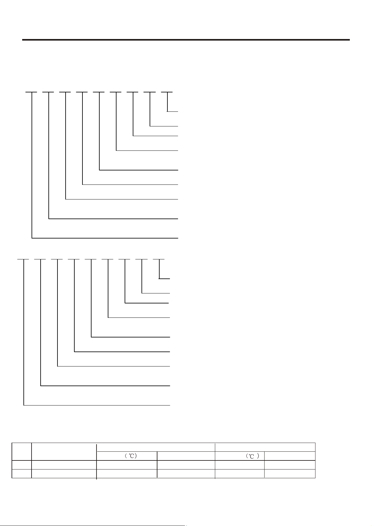
a) Description of the coding rule of the models
A U 36 N A I B D A
Climate type:T1
Design serial number
Product type: heat pump R407C
Appearance features
Product series:one-tag-one
Adaptive voltage:380-400V/50Hz
Product specification:valid digit above kilobi
Outdoor unit
Air conditioner
A B 36 N A C B D A
b). Standard working condition
Climate type:T1
Design serial number
Product type: heat pump R407C
Appearance features
Product series:one-tag-one
Adaptive voltage:380-400V/50Hz
Product specification:valid digit above kilobi
Product type:indoor unit
P:Cabinet typeC:Convertible type
B:Cassette type D:Duct type
Air conditioner
No.
No.
1
1
2
2
Operating Mode
Nominal Cooling
Nominal Heating
Nominal Heating
Indoor Operating Mode
Temp.
DB:27
DB:27
DB:20
DB:20
Humidity
Humidity
WB:19
WB:19
WB:15
WB:15
2
Outdoor Operating Mode
Temp.
Temp.
DB:35
DB:35
DB:7 WB:6
DB:7 WB:6
Humidity
Humidity
WB:24
WB:24

c)Brif introduction of the series:
Convertible type:
AC36NACBEA+AU36NAIBEA AC42 NACBDA+AU42NAIBEA
(1).Ceiling convertible,flexible installation,convenient
maintenance,saving the users' expenditures
(2).Adopting three-phase power supply,applicable for household
and commercial usage
(3).Dual air outlet design,floor air blowing,accelerating the indoor air
circulation, quick temperature adjustment
(4).Long-distance air blowing,large power,large cooling/heating
ratio
(5).Intelligent remote control,convenient and flexible control
(6).Super-slim indoor unit design,luxury and nice-looking,saving
space,harmonious and unitive with the indoor environment
(7).Adopting screw-fastening for the air inlet grill,firmly
fixed;adopting slipway insert-lock fastening method for the
filter screen,convenient cleaning or replacing the filter screen
without opening the air inlet grill.
(8).Group control,units up to 128 sets can be controlled .
Duct type :
AD36NAMBEA+AU36NAIBEA AD42NAMBEA+AU42 NAIBEA
Totally concealed machine body
All the machine body is to be installed inside the ceiling, having no effect on the
beauty of the room and without taking any room space.
Air intake via the rear air intake duct
This new design has changed the former unique pattern of air intake, and a larger
distance between air intake and air return cycles as well as better air quality can be
achieved.
Flexible and easier installation
The machine body is to be installed in a totally concealed way,its fan system has
a longer distance coverage so as to supply its airflow to several rooms, and the
indoor unit may be installed inside the ceiling of a room or corridor. The
installation is simple and flexible, and there is no need to have specified personnel
for management, thus cutting down the expenses; the machine is lighter and
smaller, and convenient for installation, it takes an extremely small building space,
thus lower the construction cost; the indoor unit is to be concealed inside the
ceiling, and hence the usable space can be saved and the room decoration will
not be affected.
3
NEW
NEW
Cassette type:
AB36NACBEA+AU36NAIBEA AB42NACBEA+AU42NAIBE A
Products characteristic:
Completely invisible machine body:
The whole machine body is completely concealed inside the ceiling. Due to its compact size it neither
breaks the harmonization of indoor decoration nor occupies the indoor spaces. The stylish look of air
conditioner allows it to blend right into ceiling.
Superbly efficient healthy filter:
Superbly efficient antibiotic materials are utilized and can prevent germs from
breeding efficiently .
Flexible and easy installation
Slim design with machine body, completely ceiling concealing and portable shape, all make it greatly
easier to install. Moreover, it occupies least constructional spaces, which help to reduce constructional
cost prices. It also features a specific drainage system with up to 600mm lift , which allows reducing
installation spaces and ensures to drain smoothly. Thanks to its "smudge-free"
mobile outlet grill,
the ceiling can be protected from pollution effectively and allow the airflow to fit people's
comfortable need much more
.
Compensation function of power failure:
When meeting a power failure during running, no matter how long it will be, once the power is
restored, air conditioner will automatic restart with the previous status.
Safety and reliable control due to various signal controls
1 Inputting with press buttons on the panel
2 Inputting with temperature sensors (indoor ambient temperature sensors, indoor coil pipe
temperature sensors,
3 Piping pressure signals
4 Compressor current signals
5 Testing signals
6 System time-shorten signal
7 Water overflowing signal
8 Communication signals between indoor unit and front plate or between indoor unit and outdoor
unit .
Silent design
The use of radial outward flow turbine fan produces larger cyde airflow volume and acts to
significantly decrease operating noise.
When using remote-controlling mode, it is comfortable and convenient to operate.
Advanced wire-controller and convenient remote-controller
The new wired controller can connect with 16 indoor units without any device such as detectors.
The new remote controller can be used for single unit or muti-free unit, or H-MRV,very convenient.
In addition, it can be compatible with the old remote controllers.
Low ambient temperature cooling function (optional)
Equipped with high/low pressure protection switch
4

d). Brief Introduction for T1\
Type of Air Conditioner
Type of Air Conditioner
Cool only 18 43 0 35 21 52
Cool only 18 43
Heat pump -7 43 -7 35 -7 52
Heat pump -7 43 -7 35 -7 52
Electricity heating 43 35 52
Electricity heating 43 35 52
T2\
T3 working condition
Climate type
Climate type
T1 T2 T3
T1 T2 T3
10
35 21 52
5
g
r
g
g
ge q
y
g
g
(
)
t
t
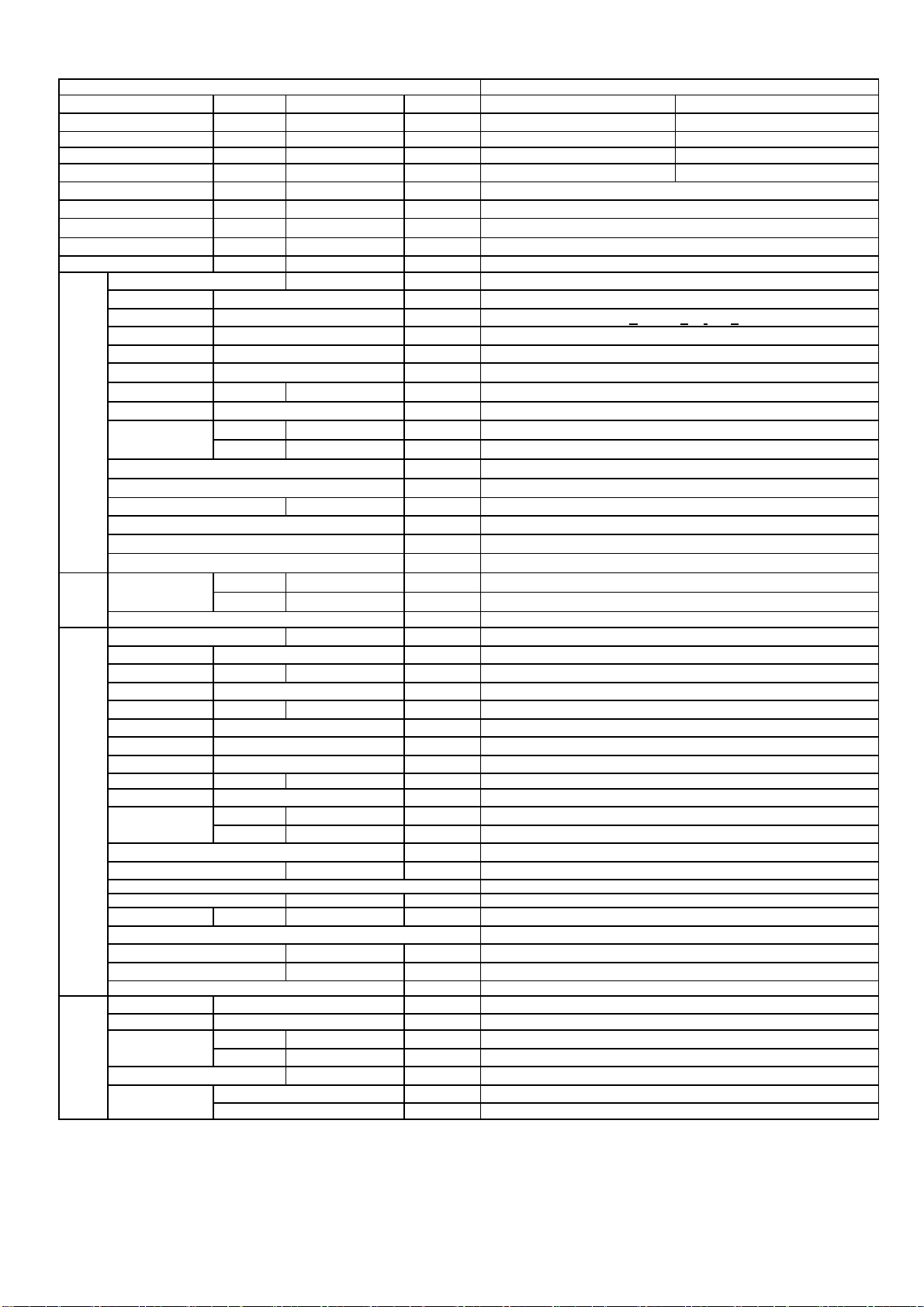
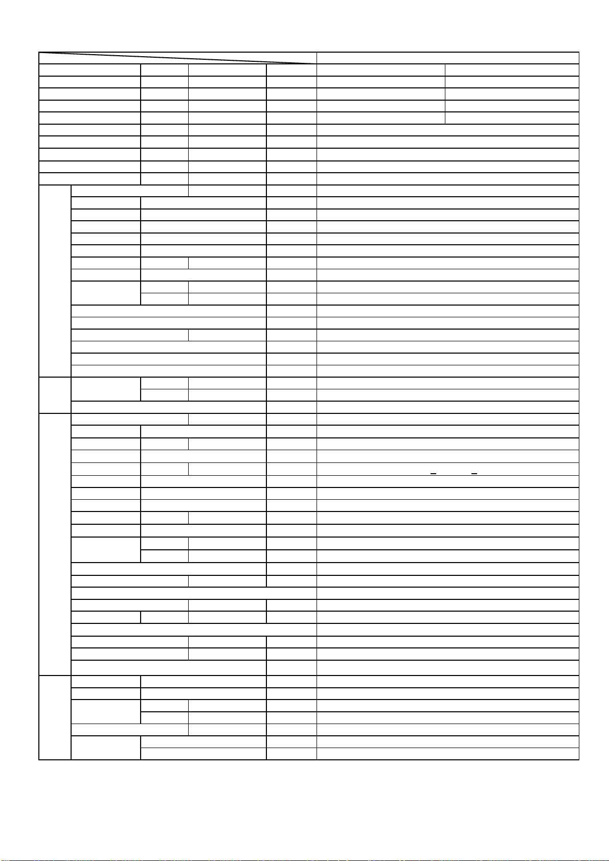
2.Specifications
item Model
Function
Capacity BTU/h
Total power inpu
Max. power inpu
EER or COP
Dehumidifying capacity
Power cable
Power source
Running /Max.Running
Start Current A
Unit model (color)
Fan Type × Number
Speed(H-M-L) r/min
Fan motor output power kW
Air-flow(H-M-L) m³/h
Heat exchanger Type / Diameter mm
Total Area m²
Temp. scope
Dimension
Indoor unit
Drainage pipe (material , I.D./O.D.) mm
Control type (Remote /wired)
Fresh air hole dimension mm
Electricity Heater
Noise level (H-M-L)
Weight (Net / Shipping)
Dimension
Panel
Weight (Net / Shipping)
Unit model (color)
Compressor Model / Manufacture
Fan Type × Number
Heat exchanger Type / Diameter mm
Dimension /
Outdoor unit
Drainage pipe (material , I.D./O.D.) mm
Refrigerant control method mm/mm
Defrostin
Volume of Accumulato
Noise level dB(A)
Type of Four way valve
material of reduce noise
crankcase heater power W
Weight (Net / Shipping)
Refrigerant Type / Charge g
Pipe
Connecting Method
PIPING
Between I.D &O.
External
Package
External
Package
Type
Speed r/min
Fan motor output power kW
Air-flow(H-M-L) m³/h
Total area m²
Temp. scope
External
Package
Rechar
Liquid mm
Gas mm
MAX.Drop 30
MAX.Piping length 50
(L×W×H)
(L×W×H)
(L×W×H)
(L×W×H)
(L×W×H)
(L×W×H)
uantit
W
W
BTU/W
10‐³×m³/h
N,V,Hz
A / A
℃
mm×mm×mm
mm×mm×mm
kW
dB(A)
kg / kg
mm×mm×mm
mm×mm×mm
kg / k
℃
mm×mm×mm
mm×mm×mm
L
k
/ k
/m
m
m
Cooling Heating
36000 41000
4000 3800
5500 5500
9 10.8
cooling:7.5/9.5;heating:6.5/9.5;
AB36NACBEA
SANYO
5
/
3N~ 380V-400V 50HZ
45
AB36NACBEA(WHITE)
Centrifugal*1
30/490+40/420+50
590+
0.06
1980/-/-
TP2M/φ7
/
2-7
1230×840×280
1325×920×370
PVC 26/32
Remote
/
/
43/41/39
46/53
1340×950×80
1400×995×115
8.4/12
/
/
/
/
/
/
/
/
/
/
/
/
/
/
/
/
/
/
/
/
R407C 3800
65
φ9.52
φ19.05
Falre
6
item Model
Function
Capacity BTU/h
Total power input
Max. power input
EER or COP
Dehumidifying capacity
W
W
BTU/W
10‐³×m³/h
Power cable
Power source
Running /Max.Running
N,V,Hz
A / A
Start Current A
Unit model (color)
Fan Type × Number
Speed(H-M-L) r/min
Fan motor output power kW
Air-flow(H-M-L) m³/h
Heat exchanger Type / Diameter mm
Total Area m²
Dimension
Indoor unit
Temp. scope
External
Package
(L×W×H)
(L×W×H)
℃
mm×mm×mm
mm×mm×mm
Drainage pipe (material , I.D./O.D.) mm
Control type (Remote /wired)
Fresh air hole dimension mm
Electricity Heater
Noise level (H-M-L)
Weight (Net / Shipping)
Dimension
External
Package
Panel
Weight (Net / Shipping)
(L×W×H)
(L×W×H)
kW
dB(A)
kg / kg
mm×mm×mm
mm×mm×mm
kg / kg
Unit model (color)
Compressor Model / Manufacture
Type
Fan Type × Number
Speed r/min
Fan motor output power kW
Air-flow(H-M-L) m³/h
Heat exchanger Type / Diameter mm
Total area m²
Temp. scope
Dimension /
Outdoor unit
Drainage pipe (material , I.D./O.D.) mm
External
Package
(L×W×H)
(L×W×H)
℃
mm×mm×mm
mm×mm×mm
Refrigerant control method mm/mm
Defrosting
Volume of Accumulator L
Noise level dB(A)
Type of Four way valve
material of reduce noise
crankcase heater power W
Weight (Net / Shipping)
kg / kg
Refrigerant Type / Charge g
Recharge quantity g/m
Pipe
Connecting Method
PIPING
Between I.D &O.
Liquid mm
Gas mm
MAX.Drop 30
MAX.Piping length 50
m
m
AC36NACBEA(SANYO)
Cooling Heating
36000 41000
4000 3800
5500 5500
9 10.8
5
/
3pH,380V-400V 50HZ
cooling:7.5/9.5;heating:6.5/9.5;
45
AC36NACBEA(WHITE)
CentrifugalX4
30/1280+30/1050+30
1350+
0.06
1600/1400/1200
TP2M/9.52
/
2-7
1920×715×235
1980×761×295
PVC 26/32
Remote
/
/
48/-/44
62/77
/
/
/
/
/
/
/
/
/
/
/
/
/
/
/
/
/
/
/
/
/
/
/
R407C 3800
65
9.52
19.05
Flare
7
D
item Model
Function
Capacity
Total power input
Max. power input
EER or COP
Dehumidifying capacity
BTU/h
W
W
BTU/W
10‐³×m³/h
Power cable
Power source
Running /Max.Running
Start Current
N,V,Hz
A / A
A
Unit model (color)
Fan Type × Number
Speed(H-M-L)
Fan motor output power
Air-flow(H-M-L)
Heat exchanger Type / Diameter
Total Area
r/min
kW
m³/h
mm
m²
Temp. scope ℃
Dimension
Indoor unit
External
Package
(L×W×H)
(L×W×H)
Drainage pipe (material , I.D./O.D.)
mm×mm×mm
mm×mm×mm
mm
Control type (Remote /wired)
Fresh air hole dimension
Electricity Heater
Noise level (H-M-L)
Weight (Net / Shipping)
Dimension
Panel
Weight (Net / Shipping)
External
Package
(L×W×H)
(L×W×H)
mm
kW
dB(A)
kg / kg
mm×mm×mm
mm×mm×mm
kg / kg
Unit model (color)
Compressor Model / Manufacture
Type
Fan Type × Number
Speed
Fan motor output power
Air-flow(H-M-L)
Heat exchanger Type / Diameter
Total area
r/min
kW
m³/h
mm
m²
Temp. scope ℃
Dimension /
External
Package
Outdoor unit
Drainage pipe (material , I.D./O.D.)
(L×W×H)
(L×W×H)
Refrigerant control method
mm×mm×mm
mm×mm×mm
mm
mm/mm
Defrosting
Volume of Accumulator
Noise level
L
dB(A)
Type of Four way valve
material of reduce noise
crankcase heater power
Weight (Net / Shipping)
Refrigerant
Type / Charge
Recharge quantity
Pipe
PIPING
Connecting Method
Between I.D &O.
Liquid
Gas
MAX.Drop 30
MAX.Piping length 50
W
kg / kg
g
g/m
mm
mm
m
m
AD36NAMBEA(SANYO)
Cooling Heating
36000 41000
4000 3800
5500 5500
9 10.8
5
/
3N 380V-400V 50HZ
cooling:7.5/9.5;heating:6.5/9.5;
45
AD36NAMBEA(WHITE)
CentrifugalX3
1050/ 960/ 870/810
0.06
2040/1800/1600
TP2M/9.52
/
2-7
1410×645×350
1557×800×370
PVC 26/32
Wired
/
/
43/-/39
55/75
/
/
/
/
/
/
/
/
/
/
/
/
/
/
/
/
/
/
/
/
/
/
/
R407C 3800
65
9.52
19.05
Flare
8
g
g
item Model
Function
Capacity BTU/h
Capacity kW
Sensible heat ratio
Total power input
Max. power input
EER or COP
Dehumidifying capacity
Power cable
Power source
Running /Max.Running
Start Current A
Unit model (color)
Type × Number
Fan
Heat exchanger
Dimension
Indoor unit
Drainage pipe (material , I.D./O.D.) mm
Control type (Remote /wired)
Fresh air hole dimension mm
Outlet distribution hole dimension mm
Electricity Heater
Noise level (H-M-L)
Weight (Net / Shipping)
Unit model (color)
Compressor
Fan
Heat exchanger
Dimension
Outdoor unit
Drainage pipe (material , I.D./O.D.) mm
Refrigerant control method mm/mm
Defrosting
Volume of Accumulator L
Noise level dB(A)
Type of Four way valve
material of reduce noise
crankcase heater power W
Weight (Net / Shipping)
Refrigerant
Pipe
PIPING
Connecting Method
Between I.D &O.
Norminal condition: indoor temperature (cooling): 27℃DB/19℃WB, indoor temperature (heating): 20℃DB
Outdoor temperature(cooling): 35℃DB/24℃WB, outdoor temperature(heating): 7℃DB/6℃WB
Speed(H-M-L) r/min
Fan motor output power kW
Air-flow(H-M-L) m³/h
Type / Diameter mm
Total Area m²
Temp. scope
External
Package
Model / Manufacture
Type
Type × Number
Speed r/min
Fan motor output power kW
Air-flow(H-M-L) m³/h
Type / Diameter mm
Total area m²
Temp. scope
External
Package
Type / Charge g
Recharge quantity g/m
Liquid mm
Gas mm
MAX.Drop 30
MAX.Piping length 50
(L×W×H)
(L×W×H)
(L×W×H)
(L×W×H)
W
W
W/W
10‐³×m³/h
N,V,Hz
A / A
℃
mm×mm×mm
mm×mm×mm
kW
dB(A)
kg / kg
℃
mm×mm×mm
mm×mm×mm
kg / kg
m
m
coolin
36000 41000
10.55 12.01
79% /
4000 3800
5500 5500
2.64 3.16
Cooling:7.5/9.5, Heating:6.5/9.5
AD36NAHBEA
3PH 380V-400V 50HZ
AD36NAHBEA (grey)
1090/1000/930
2580/2070/1560
1197×828×355
1450×980×530
R407C 3800
heatin
5
/
45
centrifugal X2
0.06
TP2M/9.52
/
2-7
PVC 26/32
wired
/
/
/
48/46/44
62/77
/
/
/
/
/
/
/
/
/
/
/
/
/
/
/
/
/
/
/
/
/
65
9.52
19.05
flared
item Model
Function
Capacity BTU/h
Total power input
Max. power input
EER or COP
Dehumidifying capacity
W
W
BTU/W
10‐³×m³/h
Power cable
Power source
Running /Max.Running
N,V,Hz
A / A
Start Current A
Unit model (color)
Fan Type × Number
Speed(H-M-L) r/min
Fan motor output power kW
Air-flow(H-M-L) m³/h
Heat exchanger Type / Diameter mm
Total Area m²
Temp. scope
Dimension /
Indoor unit
External
Package
(L×W×H)
(L×W×H)
℃
mm×mm×mm
mm×mm×mm
Drainage pipe (material , I.D./O.D.) mm
Control type (Remote /wired)
Fresh air hole dimension mm
Electricity Heater
Noise level (H-M-L)
Weight (Net / Shipping)
Dimension /
Panel
Weight (Net / Shipping)
External
Package
(L×W×H)
(L×W×H)
kW
dB(A)
kg / kg
mm×mm×mm
mm×mm×mm
kg / kg
Unit model (color)
Compressor Model / Manufacture
Type
Fan Type × Number
Speed r/min
Fan motor output power kW
Air-flow(H-M-L) m³/h
Heat exchanger Type / Diameter mm
Total area m²
Temp. scope
Dimension
Outdoor unit
Drainage pipe (material , I.D./O.D.) mm
External
Package
(L×W×H)
(L×W×H)
℃
mm×mm×mm
mm×mm×mm
Refrigerant control method mm/mm
Defrosting
Volume of Accumulator L
Noise level dB(A)
Type of Four way valve
material of reduce noise
crankcase heater power W
Weight (Net / Shipping)
kg / kg
Refrigerant Type / Charge g
Recharge quantity g/m
Pipe
Connecting Method
PIPING
Between I.D &O.
Liquid mm
Gas mm
MAX.Drop 30
MAX.Piping length 50
m
m
AU36NAIBEA(SANYO)
Cooling Heating
36000 41000
4000 3800
5500 5500
9 10.8
5
/
3N380V-400V 50HZ
cooling:7.5/9.5;heating:6.5/9.5;
45
/
/
/
/
/
/
/
/
/
/
/
/
/
/
/
/
/
AU36NAIBEA(WHITE)
C-SBN303H8A(SANYO)
Scroll
Axial-flow×2
840+30
0.15
6000
TP2M/9.52
0.92
43-60
980×340×1250
1050×440×1375
/
Capiliary
AUTO
/
64/-/-
DHF-12
XPE
/
91/111
R407C 3800
65
9.52
19.05
Flare
9
g
r
g
g
ge q
y
g
g
item model
EA
t
t
Function
Capacity BTU/h
Total power inpu
Max. power inpu
EER or COP
Dehumidifying capacity
W
W
BTU/W
10‐³×m³/h
Power cable
Power source
Running /Max.Running
current
N,V,Hz
A / A
Start Current A
Unit model (color)
Fan Type × Number
Speed(H-M-L) r/min
Fan motor output power kW
Air-flow(H-M-L) m³/h
Heat exchanger Type / Diameter mm
Total Area m²
Dimension
Indoor unit
Temp. scope
External
Package
(L×W×H)
(L×W×H)
℃
mm×mm×mm
mm×mm×mm
Drainage pipe (material , I.D./O.D.) mm
Control type (Remote /wired)
Fresh air hole dimension mm
Electricity Heater
Noise level (H-M-L)
Weight (Net / Shipping)
Dimension
Panel
Weight (Net / Shipping)
External
Package
(L×W×H)
(L×W×H)
kW
dB(A)
kg / kg
mm×mm×mm
mm×mm×mm
kg / k
Unit model (color)
Compressor Model / Manufacture
Type
Fan Type × Number
Speed r/min
Fan motor output power kW
Air-flow(H-M-L) m³/h
Heat exchanger Type / Diameter mm
Total area m²
Temp. scope
Dimension
Outdoor unit
Drainage pipe (material , I.D./O.D.) mm
External
Package
(L×W×H)
(L×W×H)
℃
mm×mm×mm
mm×mm×mm
Refrigerant control method mm/mm
Defrostin
Volume of Accumulato
L
Noise level dB(A)
Type of Four way valve /
material of reduce noise
crankcase heater power W
Weight (Net / Shipping) /
k
/ k
Refrigerant Type / Charge g
Pipe
Connecting Method
PIPING
Between I.D &O.
Rechar
Liquid mm
Gas mm
MAX.Drop 30
MAX.Piping length 50
uantit
/m
m
m
AB42NACB
Cooling Heating
42000 48000
4800 5000
5700 7200
8.75 9.6
5
/
3N~ 380V-400V 50HZ
Cooling:8.3/10.2;Heating:9.5/12.6;
59.5
AB42NACBEA(WHITE)
Centrifugal
30/490+40/420+50
590+
0.06
1980/-/-
TP2M/φ7
/
2-7
1230×840×280
1325×920×370
PVC 26/32
Remote control
/
/
43/41/39
46/53
1340×950×80
1400×995×115
8.4/12
/
/
/
/
/
/
/
/
/
/
/
/
/
/
/
/
/
/
/
R407C 4000
65
φ9.52
φ19.05
Flare
10
Item model
Function
Capacity BTU/h
Total power input
Max. power input
EER or COP
Dehumidifying capacity
Power cable
Power source
Running /Max.Running
Start Current A
Unit model (color)
Fan Type × Number
Speed(H-M-L) r/min
Fan motor output power kW
Air-flow(H-M-L) m³/h
Heat exchanger Type / Diameter mm
Total Area m²
Temp. scope
Dimension
Indoor unit
Drainage pipe (material , I.D./O.D.) mm
Control type (Remote /wired)
Fresh air hole dimension mm
Electricity Heater
Noise level (H-M-L)
Weight (Net / Shipping)
Dimension
Panel
Weight (Net / Shipping)
Unit model (color)
Compressor Model / Manufacture
Fan Type × Number
Heat exchanger Type / Diameter mm
Dimension
Outdoor unit
Drainage pipe (material , I.D./O.D.) mm
Refrigerant control method mm/mm
Defrosting
Volume of Accumulator L
Noise level dB(A)
Type of Four way valve
material of reduce noise
crankcase heater power W
Weight (Net / Shipping)
Refrigerant Type / Charge g
Pipe
Connecting Method
PIPING
Between I.D &O.
External
Package
External
Package
Type
Speed r/min
Fan motor output power kW
Air-flow(H-M-L) m³/h
Total area m²
Temp. scope
External
Package
Recharge quantity g/m
Liquid mm
Gas mm
MAX.Drop 30
MAX.Piping length 50
(L×W×H)
(L×W×H)
(L×W×H)
(L×W×H)
(L×W×H)
(L×W×H)
W
W
BTU/W
10‐³×m³/h
N,V,Hz
A / A
℃
mm×mm×mm
mm×mm×mm
kW
dB(A)
kg / kg
mm×mm×mm
mm×mm×mm
kg / kg
℃
mm×mm×mm
mm×mm×mm
kg / kg
m
m
AC42NACBEA(SANYO)
Cooling Heating
42000 48000
4800 5000
5700 7200
8.75 9.6
5
/
3N380V-400V 50HZ
Cooling:8.3/10.2;Heating:9.5/12.6;
49.5
AC42NACBEA(WHITE)
CentrifugalX2
30/1280+30/1050+30
1350+
0.06
1600/1400/1200
TP2M/9.52
/
2-7
1920×715×235
1980×761×295
PVC 26/32
Remote
/
/
48/-/44
62/77
/
/
/
/
/
/
/
/
/
/
/
/
/
/
/
/
/
/
/
/
/
/
/
/
R407C 4000
65
9.52
19.05
Flare
11

Item model
Function
Capacity BTU/h
Total power input
Max. power input
EER or COP
Dehumidifying capacity
Power cable
Power source
Running /Max.Running
Start Current A
Unit model (color)
Fan Type × Number
Speed(H-M-L) r/min
Fan motor output power kW
Air-flow(H-M-L) m³/h
Heat exchanger Type / Diameter mm
Total Area m²
Temp. scope
Dimension
Indoor unit
Drainage pipe (material , I.D./O.D.) mm
Control type (Remote /wired)
Fresh air hole dimension mm
Electricity Heater
Noise level (H-M-L)
Weight (Net / Shipping)
Dimension
Panel
Weight (Net / Shipping)
Unit model (color)
Compressor Model / Manufacture
Fan Type × Number
Heat exchanger Type / Diameter mm
Dimension
Outdoor unit
Drainage pipe (material , I.D./O.D.) mm
Refrigerant control method mm/mm
Defrosting
Volume of Accumulator L
Noise level dB(A)
Type of Four way valve
material of reduce noise
crankcase heater power W
Weight (Net / Shipping)
Refrigerant Type / Charge g
Pipe
Connecting Method
PIPING
Between I.D &O.
External
Package
External
Package
Type
Speed r/min
Fan motor output power kW
Air-flow(H-M-L) m³/h
Total area m²
Temp. scope
External
Package
Recharge quantity g/m
Liquid mm
Gas mm
MAX.Drop 30
MAX.Piping length 50
(L×W×H)
(L×W×H)
(L×W×H)
(L×W×H)
(L×W×H)
(L×W×H)
W
W
BTU/W
10‐³×m³/h
N,V,Hz
A / A
℃
mm×mm×mm
mm×mm×mm
kW
dB(A)
kg / kg
mm×mm×mm
mm×mm×mm
kg / kg
℃
mm×mm×mm
mm×mm×mm
kg / kg
m
m
AD42NAMBEA(SANYO)
Cooling Heating
42000 48000
4800 5000
5700 7200
8.75 9.6
5
5X2.5mm
2
3N380V-400V 50HZ
cooling:8.3/10.2;heating:9.5/12.6;
49.5
AD42NAMBEA(WHITE)
CentrifugalX3
1050/960/ 870/810
0.06
2040/1800/1600
TP2M/9.52
/
2-7
1410×645×350
1450×9800×530
PVC 26/32
Wired
/
/
42/36/30
55/75
/
/
/
/
/
/
/
/
/
/
/
/
/
/
/
/
/
/
/
/
/
/
/
R407C 4000
65
9.52
19.05
Flare
12
g
g
item Model
Function
Capacity BTU/h
Capacity kW
Sensible heat ratio
Total power input
Max. power input
EER or COP
Dehumidifying capacity
Power cable
Power source
Running /Max.Running
Start Current A
Unit model (color)
Type × Number
Fan
Heat exchanger
Dimension
Indoor unit
Drainage pipe (material , I.D./O.D.) mm
Control type (Remote /wired)
Fresh air hole dimension mm
Outlet distribution hole dimension mm
Electricity Heater
Noise level (H-M-L)
Weight (Net / Shipping)
Unit model (color)
Compressor
Fan
Heat exchanger
Dimension
Outdoor unit
Drainage pipe (material , I.D./O.D.) mm
Refrigerant control method mm/mm
Defrosting
Volume of Accumulator L
Noise level dB(A)
Type of Four way valve
material of reduce noise
crankcase heater power W
Weight (Net / Shipping)
Refrigerant
Pipe
PIPING
Connecting Method
Between I.D &O.
Norminal condition: indoor temperature (cooling): 27℃DB/19℃WB, indoor temperature (heating): 20℃DB
Outdoor temperature(cooling): 35℃DB/24℃WB, outdoor temperature(heating): 7℃DB/6℃WB
Speed(H-M-L) r/min
Fan motor output power kW
Air-flow(H-M-L) m³/h
Type / Diameter mm
Total Area m²
Temp. scope
External
Package
Model / Manufacture
Type
Type × Number
Speed r/min
Fan motor output power kW
Air-flow(H-M-L) m³/h
Type / Diameter mm
Total area m²
Temp. scope
External
Package
Type / Charge g
Recharge quantity g/m
Liquid mm
Gas mm
MAX.Drop 30
MAX.Piping length 50
(L×W×H)
(L×W×H)
(L×W×H)
(L×W×H)
W
W
W/W
10‐³×m³/h
N,V,Hz
A / A
℃
mm×mm×mm
mm×mm×mm
kW
dB(A)
kg / kg
℃
mm×mm×mm
mm×mm×mm
kg / kg
m
m
coolin
42000 48000
12.31 14.06
79% /
4800 5000
5700 7200
2.56 2.81
Cooling: 8.3/10.2, Heating: 9.5/12.6
AD42NAHBEA
3PH 380V-400V 50HZ
AD42NAHBEA (grey)
1090+30/-/930+50
1197×828×355
1450×980×530
R407C 4000
heatin
5
/
49.5
centrifugal X2
0.06
2580/-/1560
TP2M/9.52
/
2-7
PVC 26/32
wired
/
/
/
48/-/44
62/77
/
/
/
/
/
/
/
/
/
/
/
/
/
/
/
/
/
/
/
/
/
65
9.52
19.05
flared
g
g
item Model
ping
Function
Capacity BTU/h
Capacity kW
Total power input
Max. power input
EER or COP
Dehumidifying capacity
W
W
W/W
10‐³×m³/h
coolin
42000 50000
12.31 14.65
5000 6000
6000 7200
2.46 2.44
Power cable
Power source
Running /Max.Running
N,V,Hz
A / A
Cooling:8.5/10.2 Heating:10.0/12.0;
1PH 380V-400V 50HZ
Start Current A
Unit model (color)
AP42NACBEA (white)
Type × Number
Fan
Speed(H-M-L) r/min
Fan motor output power kW
590/400/350
Air-flow(H-M-L) m³/h
Type / Diameter mm
Heat exchanger
Indoor unit
Dimension
Total Area m²
Temp. scope
External
Package
(L×W×H)
(L×W×H)
℃
mm×mm×mm
mm×mm×mm
1820×530×310
1952×660×455
Drainage pipe (material , I.D./O.D.) mm
Control type (Remote /wired)
Noise level (H-M-L)
Weight (Net / Shipping)
Refrigerant
Pipe
PIPING
Connecting Method
Between I.D &O.
Norminal condition: indoor temperature (cooling): 27℃DB/19℃WB, indoor temperature (heating): 20℃DB
Outdoor temperature(cooling): 35℃DB/24℃WB, outdoor temperature(heating): 7℃DB/6℃WB
Type / Charge g
Recharge quantity g/m
Liquid mm
Gas mm
MAX.Drop 30
MAX.Pi
length 50
dB(A)
kg / kg
R407C 4000
m
m
AP42NACBEA
heatin
5
/
49.5
centrifugalX1
0.06
1560/-/-
TP2M/9.52
0.338
2-7
PVC 26/32
wired control
48/-/44
62/77
/
9.52
19.05
flared
Item model
Function
Capacity BTU/h
Total power input
Max. power input
EER or COP
Dehumidifying capacity
W
W
BTU/W
10‐³×m³/h
Power cable
Power source
Running /Max.Running
N,V,Hz
A / A
Start Current A
Unit model (color)
Fan Type × Number
Speed(H-M-L) r/min
Fan motor output power kW
Air-flow(H-M-L) m³/h
Heat exchanger Type / Diameter mm
Total Area m²
Dimension
Indoor unit
Temp. scope
External
Package
(L×W×H)
(L×W×H)
℃
mm×mm×mm
mm×mm×mm
Drainage pipe (material , I.D./O.D.) mm
Control type (Remote /wired)
Fresh air hole dimension mm
Electricity Heater
Noise level (H-M-L)
Weight (Net / Shipping)
Dimension /
Panel
Weight (Net / Shipping)
External
Package
(L×W×H)
(L×W×H)
kW
dB(A)
kg / kg
mm×mm×mm
mm×mm×mm
kg / kg
Unit model (color)
Compressor Model / Manufacture
Type
Fan Type × Number
Speed r/min
Fan motor output power kW
Air-flow(H-M-L) m³/h
Heat exchanger Type / Diameter mm
Total area m²
Temp. scope
Dimension
Outdoor unit
Drainage pipe (material , I.D./O.D.) mm
External
Package
(L×W×H)
(L×W×H)
℃
mm×mm×mm
mm×mm×mm
Refrigerant control method mm/mm
Defrosting
Volume of Accumulator L
Noise level dB(A)
Type of Four way valve
material of reduce noise
crankcase heater power W
Weight (Net / Shipping)
kg / kg
Refrigerant Type / Charge g
Recharge quantity g/m
Pipe
Connecting Method
PIPING
Between I.D &O.
Liquid mm
Gas mm
MAX.Drop 30
MAX.Piping length 50
m
m
AU42NAIBEA(SANYO)
Cooling Heating
42000 48000
4800 5000
5700 7200
8.75 9.6
5
/
3N380V-400V 50HZ
Cooling:8.3/10.2;Heating:9.5/12.6;
49.5
/
/
/
/
/
/
/
/
/
/
/
/
/
/
/
/
/
/
AU42NAIBEA(WHITE)
C-SBN373H8A(SANYO)
Scroll
Axial-flow×2
1180+30 840+30
0.15
6000
TP2M/9.52
0.92
43-60
980×340×1225
1050×440×1375
PVC 26/32
Capiliary
Auto
/
64/-/-
DHF-12
XPE
42
91/116
R407C 4000
65
9.52
19.05
Flare
13
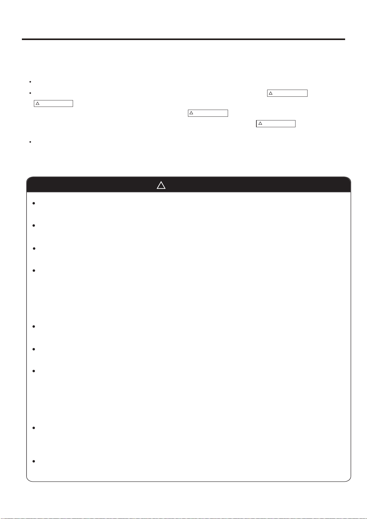
SAFETY PRECAUTIONS
3 SAFETY PRECAUTIONS
Please read these "Safety Precautions" first then accurately execute the installation work.
Though the precautionary points indicated herein are divided under two headings, and
those points which are related to the strong possibility of an installation done in error
CAUTION
resulting in death or serious injury are listed in the section. However, there is also a
possibility of serious consequences in relationship to the points listed in the section as well.
In either case, important safety related information is indicated, so by all means, properly observe all that is mentioned.
After completing the installation, along with confirming that no abnormalities were seen from the operation tests, please
explain operating methods as well as maintenance methods to the user (customer) of this equipment, based on the owner's
manual.
Moreover, ask the customer to keep this sheet together with the owner's manual.
WARNING
WARNING
CAUTION
WARNING
This system should be applied to places of office, restaurant, residence and the like. Appliaction to inferior
environment such as engineering shop could cause equipment malfunction.
Please entrust installation to either the company which sold you the equipment or to a professional contractor.
Defects from improper installations can be the cause of water leakage, electric shocks and fires.
Execute the installation accurately, based on following the installation manual. Again, improper installations can
result in water leakage, electric shocks and fires.
When a large air-conditioning system is installed to a small room, it is necessary to have a prior planned
countermeasure for the rare case of a refrigerant leakage, to prevent the exceeding of threshold concentration.
In regards to preparing this countermeasure, consult with the company from which you purchased the equipment,
and make the installation accordingly. In the rare event that a refrigerant leakage and exceeding of threshold
concentration does occur,there is the danger of a resultant oxygen deficiency accident.
For installation, confirm that the installation site can sufficiently support heavy weight. When strength is insufficient,
injury can result from a falling of the unit.
Execute the prescribed installation construction to prepare for earthquakes and the strong winds of typhoons and
hurricanes, etc. Improper installations can result in accidents due to a violent falling over of the unit.
For electrical work, please see that a licensed electrician executes the work while following the safety standards
related to electrical equipment, and local regulations as well as the installation instructions, and that only exclusive
use circuits are used.
Insufficient power source circuit capacity and defective installment execution can be the cause of electric shocks and
fires.
Accurately connect wiring using the proper cable, and insure that the external force of the cable is not conducted to
the terminal connection part, through properly securing it. Improper connection or securing can result in heat
generation or fire.
Take care that wiring does not rise upward, and accurately install the lid/service panel. Its improper installation can
also result in heat generation or fire.
- 14-
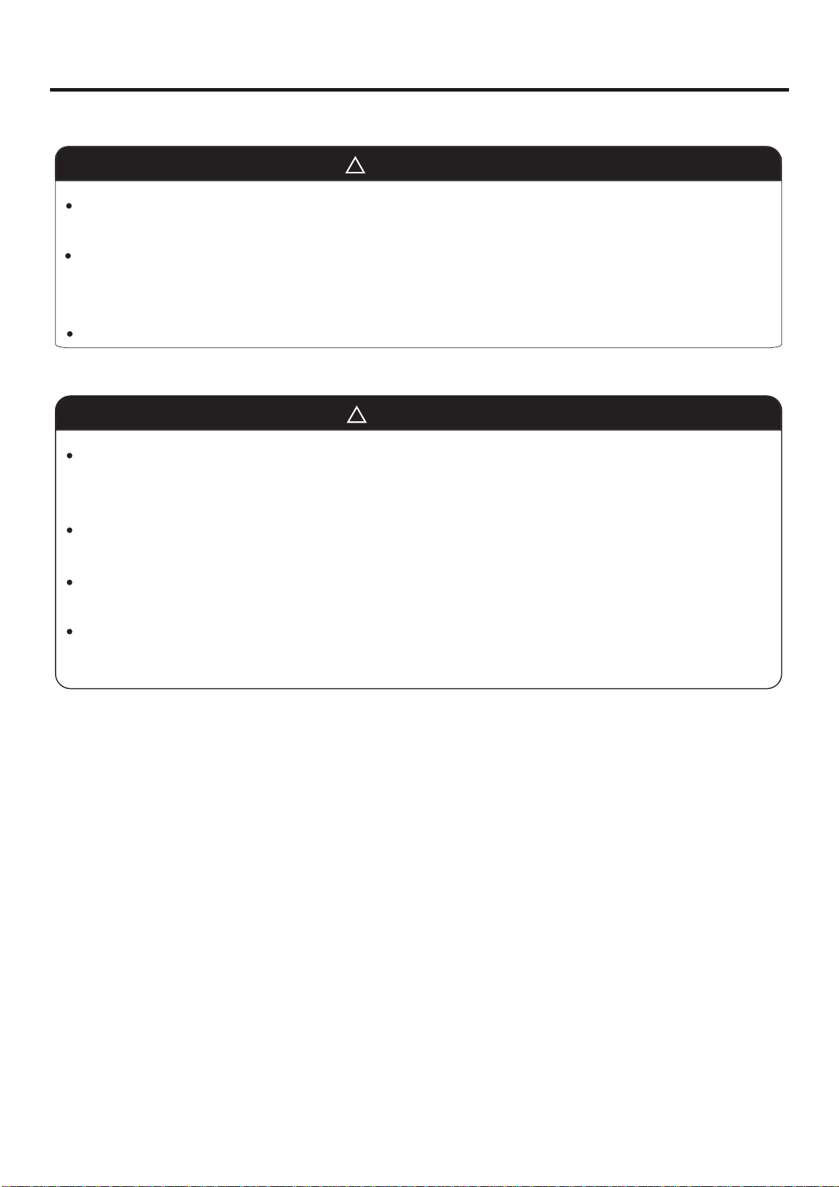
SAFETY PRECAUTIONS
WARNING
When setting up or moving the location of the air conditioner, do not mix air etc. or anything other than the designated
refrigerant (please see nameplate) within the refrigeration cycle.
Rupture and injury caused by abnormal high pressure can result from such mixing.
Always use accessory parts and authorized parts for installation construction. Using parts not authorized by this
company can result in water leakage, electric shock, fire and refigerant leakage.
The position of indoor unit must be above the floor 2.5m.
CAUTION
Execute proper grounding. Do not connect the ground wire to a gas pipe, water pipe, lightening rod or a telephone
ground wire.
Improper placement of ground wires can result in electric shock.
The installation of an earth leakage breaker is necessary depending on the established location of the unit. Not
installing an earth leakage breaker may result in electric shock.
Do not install the unit where there is a concern about leakage of combustible gas.
The rare event of leaked gas collecting around the unit could result in an outbreak of fire.
For the drain pipe, follow the installation manual to insure that it allows proper drainage and thermally insulate it to
prevent condensation. Inadequate plumbing can result in water leakage and water damage to interior items.
-15
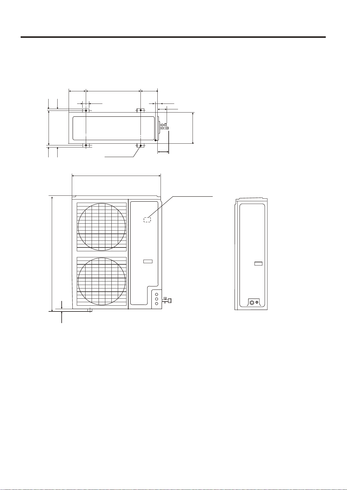
3 Net dimensionsof indoor unit and outdoor unit
1)Outdoor unit
185 185
1818
38
380
38
70
580
Screw Hole
(M10)
950
30
52
340
88
Power wiring Terminal
1250
25
16
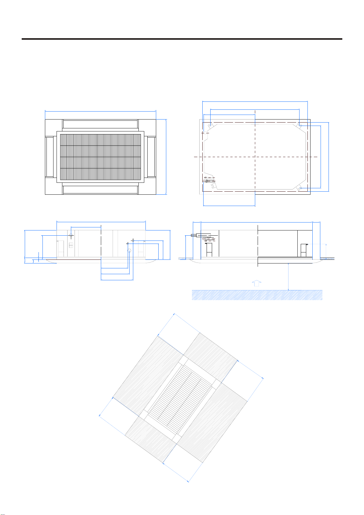
2)Indoor unit
NET DIMENSIONS OF INDOOR AND OUTDOOR UNIT
Model: AB36NACBEA Cassette type Indoor unit
1340
295
280
220
20
30
50
840
260
270
315
950
160
135
300
220
615
615
1250-1280
1070
(ceiling hole)
(hanging position)
123055 55
mm
over1000
780
860-890
155
over1500
over1500
over1500
over1500
- 17 -
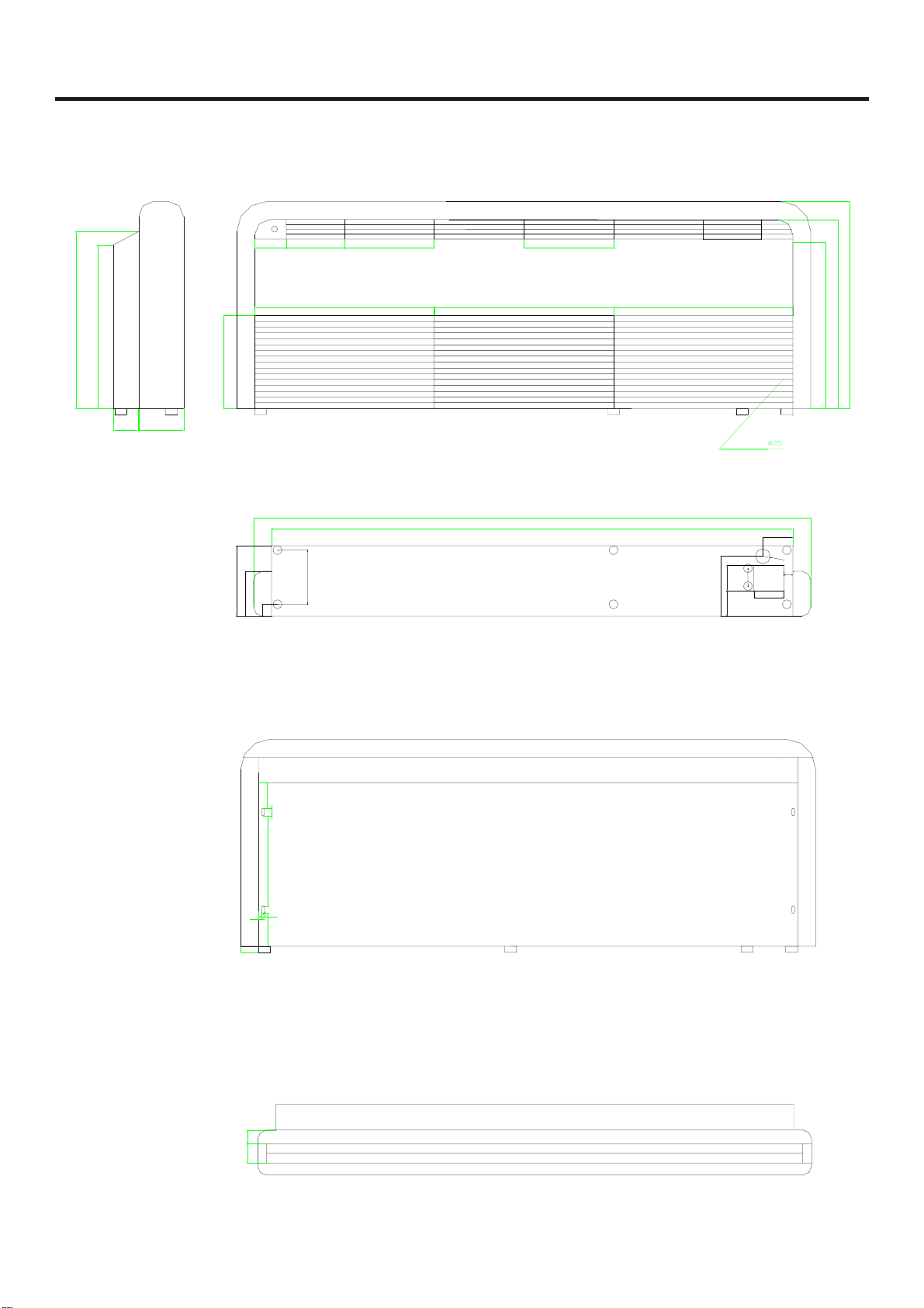
Model: AC36NACBEA Convertible Indoor unit
195
105
NET DIMENSIONS OF INDOOR AND OUTDOOR UNIT
300300
590
545
85 150
310
235
150
600
180
40
600
1920
1800
600
drainage pipe
85
195
85
690
630
555
100
R15
30
60
100
85
25
300
10
10
110
60
45
65
18
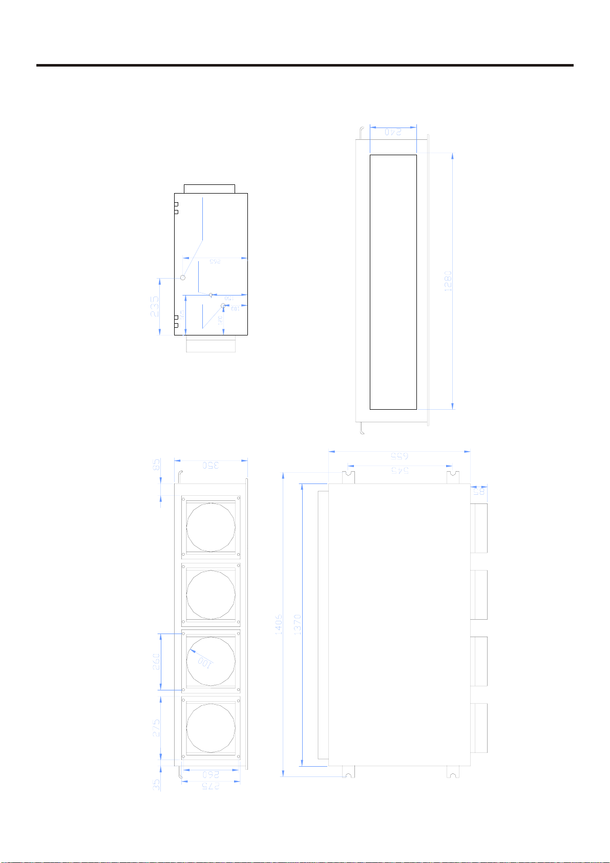
NET DIMENSIONS OF INDOOR AND OUTDOOR UNIT
Model: AD36NAMBEA AD42NAMBEA
drainage pipe
liquid pipe
gas pipe
A-A
19
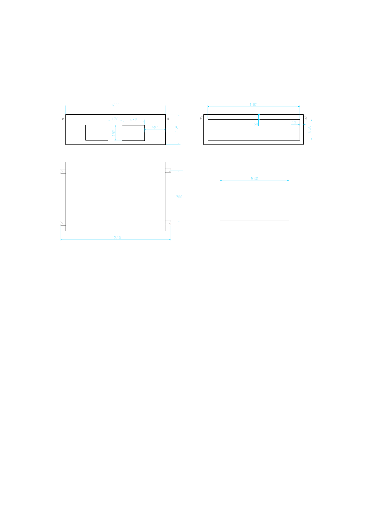
Model: AD36NAHBEA AD42NAHBEA
INSTALLATION INSTRUCTIONS
5 INSTALLATION INSTRUCTIONS
5.1 Cassette type
5.1.1 Installation tools
1. Cross screwdriver 2 .Metal saw 3 .60,70mm drill 4. Inner hexagon spanner,
shifting spanner 5 .Spanner(14, 17, 19,24,27mm diameter) 6. Pipe cutter
7. Pipe expander 8. Knife 9 .Pliers 10. Leak detector or soap liquor
11. Measuring tape 12 .Scraper 13. Refrigeration oil 14 .Vacuum pump
15 .Flat screwdriver
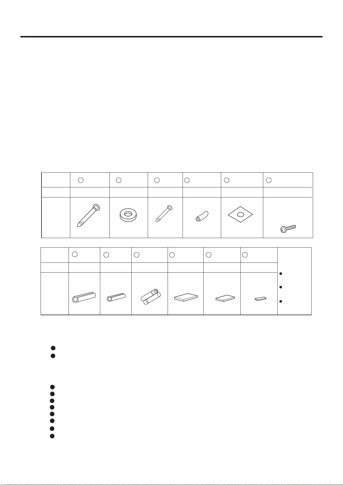
5.1.2 Standard accessories
Please check if your unit is delivered with following
Part name
QTY
Shape
Clamp
2 Piece
Washer
8 Piece
Clamp Paper pattern
6 Piece
Drain hose
1 Piece
54
1 Set
6321
Screw(M5 size)
3 Piece
For installation
of
paper pattern
Part name
QTY
Shape
7
Insulator
1 Piece 1 Piece
8 9
Insulator Sealing pad Sealing pad Sealing pad
For liquid pipeFor gas pipe
Dry battery
2 Piece 1 Piece 1 Piece 2 Piece
R03, 7#
5.1.3 Installation of indoor unit
5.1.3.1 Before installation
Determine the way kto carry unit to installation place.
Don't remove packing until unit reaches installation place.
If unpacking is unkavoidable, protect unit properly.
5.1.3.2 Selection of installation place
(1) Installation place shall meet the following and agreed by customers:
Place where proper air flow can be ensured.
No block to air flow.
Water drainage is smpoth.
Place strong enough to support unit weight.
Place where inclination is not evident on ceiling.
Enough space for mainenance.
Indoor and outdoor unit piping length is within limit. (Refer to Installation Manual for outdoor unit.)
Indoor and outdoor unit, power cable, inter unit cable are at least 1 m away fromT.V. radio. This
is helpful to avoid picture disturbance and noise. (Even if 1 m is kept, noise can still appear if radio
wave is strong)
1110
12
[Other]
Operation
Small sizeMedium sizeLarge size
Manual
Ornament
panel
Remote
controller
- 20 -
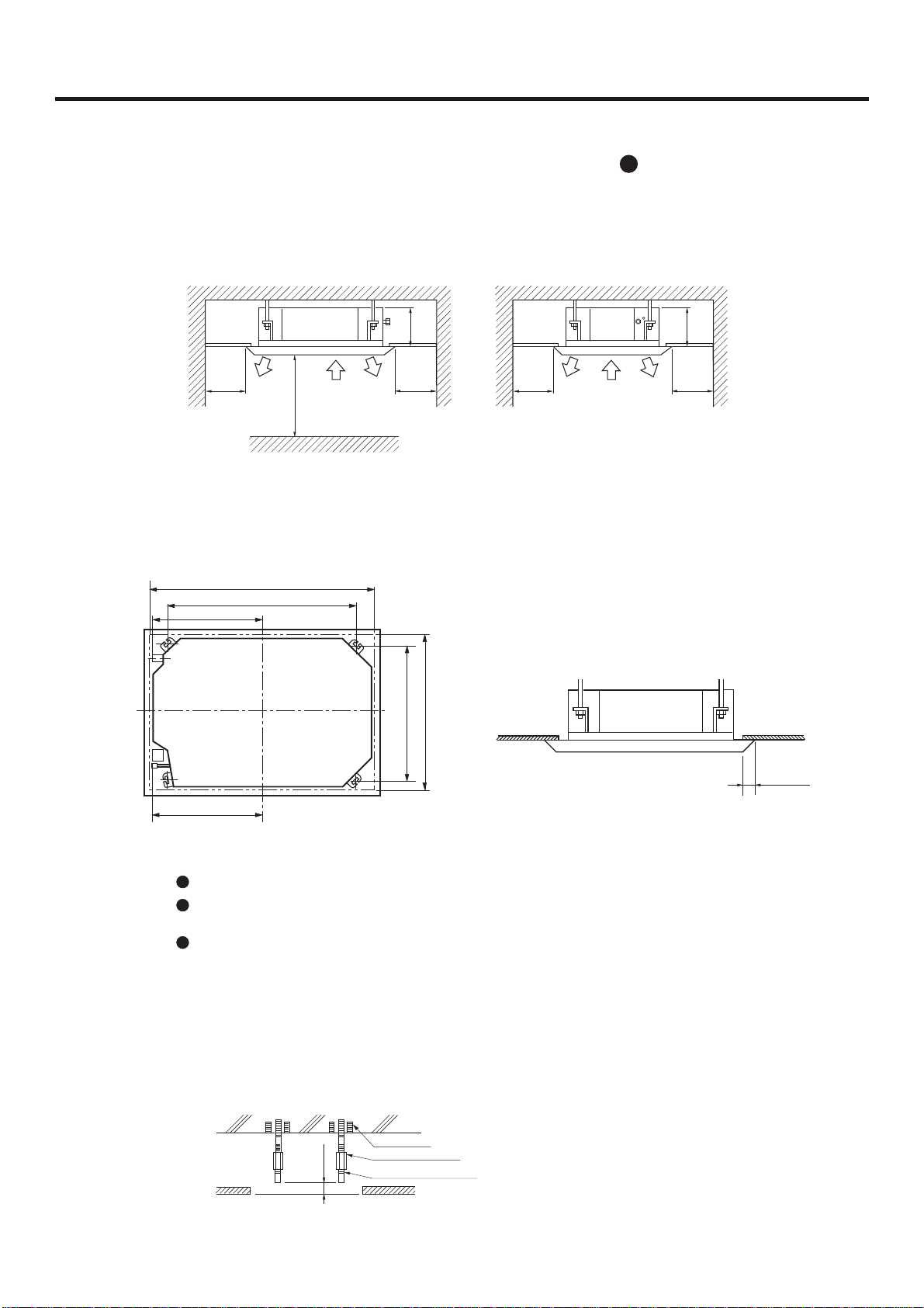
INSTALLATION INSTRUCTIONS
(2) Ceiling height
Indoor unit can be installed on ceiling of 2.5-3m in height. (Refer to Foeld setting and Installation
8
Manual of ornament panel.)
(3) Install suspending bolt. Check if the installation place is strong enough to hold weight. Take
necessary measures in case it is not safe. (Distance between holes are marked on paper pattern.
Refer to paper pattern for place need be reinforced)
Installation space
Air outlet
1500 Over
Air outlet
Air inlet
2500 Over
260
1500 Over
Air outlet
1500 Over
Air inlet
Air inlet
260
1500 Over
5.1.3.3 Preparation
(1) Position of ceiling opening between unit and suspending bolt.Unit: mm
890(Ceiling opening)
1070
(Distance between suspending bolts)
515
(Distance between suspending bolts)
515
860(Ceiling opening)
780
20 Over
(2) Cut an opening in ceiling for installation if necessary. (when ceiling already exists.)
Refer to paper pattern for dimension of ceiling hole.
Connect all pipings (refrigerant, water drainage), wirings (inter unit cable) to indoor unit, before
installation.
Cut a hole in ceiling, may be a frame should be used to ensure a smooth surface and to prevent
vibration. Contact your real estate dealer
(3) Install a suspending bolt.
(Use a M10 bolt)
To support the unit weight, anchor bolt shall be used in the case of already exists ceiling. For new
ceiling, use built-in type bolt or parts prepared in the field.
Before going on installing adjust space between ceiling.
<Installation example>
Roof
Anchor bolt
Long nut
50~100
Suspending bolt
Ceiling
Note: All the above mentioned parts shall be prepared in field.
- 21 -
INSTALLATION INSTRUCTIONS
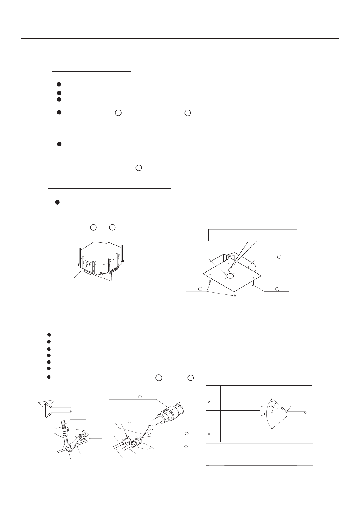
5.1.3.4 Installation
In the case of new ceiling
(1) Install unit temporally
Put suspending bracket on the suspending bolt. Be sure to use nut and washer at both ends of the bracket.
(2) As for the dimensions of ceiling hole, see paper pattern. Ask your real estate dealer for details.
Center of the hole is marked on the paper pattern.
Center of the unit is marked on the card in the unit and on the paper pattern.
Mount paper pattern onto unit using 3 screws . Fix the corner of the drain pan at piping outlet.
< After installation on the ceiling >
(3) Adjust unit to its right position. (Refer to preparation for the installation-(1))
(4) Check unit's horizontal level.
Watert pump and flating switch is installed inside indoor unit, check four corners of the unit for its level using
horizontal compartor or PVC tube with water. (If unit is tilting against the direction of water drainage, problem
may occur on floating switch, causing water leakage.)
(5) Remove the washer mounlting , and tighten the nut above.
(6) Remove the paper pattern.
In the case of ceiling already exists
(1) Install unit temporally
Put suspending bracket on the suspending bolt. Be sure to use nut and washer at both ends of the
bracket. Fix the bracket firmly.
(2) Adjust the height and position of the unit. (Refer to preparation for the installation (1) ).
(3) Proceed with and of "In the case of new ceiling".
3
4
5
7
4
Scrtews at the piping outlet is fixed at the corner
of drain pan.
Level
Polythene pipe
Center of ceiling hole Paper pattern
5
Screw
(accessory)
Paper pattern
4
Screw (accessory)
5
[Fix the paper pattern]
5.1.3.5 Refrigerant piping
As for outdoor piping, please refer to installation Manual of outdoor unit.
Outdoor is precharged with refrigerant.
Be sure to see the Fig.1, when connecting and removing piping from unit.
For the size of the flare nut, please refer to Table 1.
Apply refrigerant oil at both inside and outsid of lflare nut. Tighten it band tight 3-4 turns then tighten it.
Use torque specified in Table 1. (Too much force may damage flare nut, causing gas leakage).
Check piping joints for gas leakage. Insulate piping as shown in Fig. below.
Cover joint of gas piping and insulator with seal .
Apple refrigerant oil
Torque spanner
Piping joing
Flare nut
Medium size seal pad 9 (accessory)
(Cover the piping joint with seal pad.)
Clip 3
spanner
Gas pipe
Liquid pipe
6
Insulator (accessory)
(For liquid pipe)
Insulator (accessory)
(For gas pipe)
9
Table 1
7
6
Diameter of Pipe
Liquid Pipe 9.52mm
Gas Pipe 19.5mm
Pipe
size
9.52
19.05
Tighten
torque
3270~3990N.cm
(333~407kgf.cm)
9720~11860N.cm
(990~1210kgf.cm)
A(mm) Flare shape
12.0~12.4
0.5
90
22.9~23.3
2
45
A
Tighten Torque
42N. m
60N. m
R0.4 ~ 0.8
- 22 -
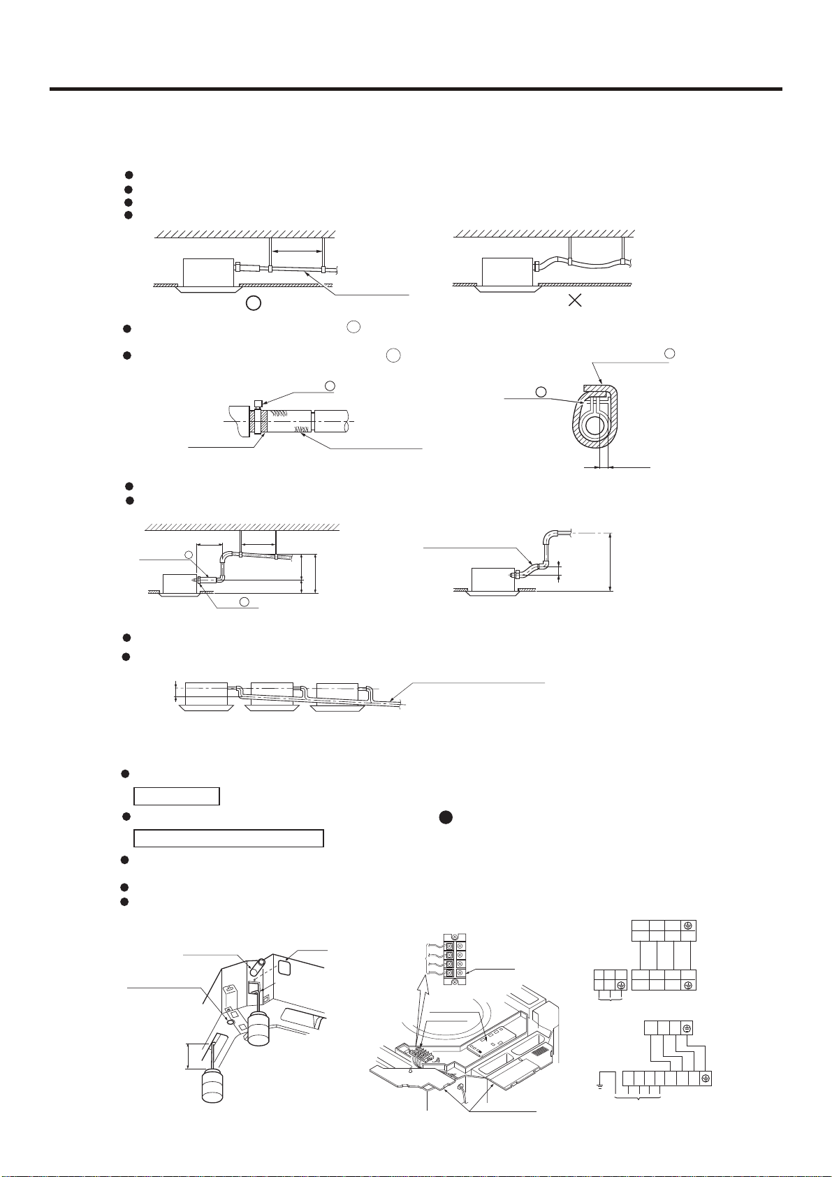
INSTALLATION INSTRUCTIONS
5.1.3.6 Installation of drainage pipe
(1) Install water drainage pipe
Pipe dia, shall be equal or larger than that of unit piping.(pipe of polyethylent; size: 25mm; O.D:32mm)
Drain pipe should be short, with a downward slope at least 1/100 to prevent air bag from happening.
If downward slope can't be made, take other measures to lift it up.
Keep a distance of 1-1.5m between suspending brackets, to make water hose straight.
1-1.5m
Slope over 1/100
Waterring can of plastic
Use the self-provided stiff pipe and clip with unit. Insert water pipe into water plug until it reaches the white tape.
Tighten the clip until head of the screw is less than 4mm from hose.
Wind the drain hose to the clip using seal pad 8 .
Insulate drain hose in the room.
Clip
Tape (White)
2
2
Self-provided stiff pipe
Clip
Clip
2
2
(accessory)
Large size seal pad
(accessory)
4mm below
10
<Cautions for the drain water lifting pipe>
Installation height shall be less than 280mm.
There should be a right angle with unit, 300mm from unit.
Suspending bracket
1~1.5m
drain water lifting pipe
Clip
2
(accessory)
280 below
500 below
220
Self-provided stiff pipe
(accessory)
75 below
500 below
Drain hose 1
(Note)
300mm below
(accessory)
The slope of water drain hose (1) shall be within 75mm, don't apply too much force on it.
If several water hoses join together, do as per following proceedures.
Connect water hoses with a T joint.
Over 100
Specifieations of the water hoses shall meet the requirements for the unit running.
(2) Check if water drainage is smooth after installation.
Charge, through air outlet or inspecting hole, 1200ccd water to see water drainage.
After wiring
Check water drainage in cooling operation. See also test run.
11
When wiring is not complete
Remove cover of control box, short connect "CHECK" terminal of the indoor unit, which is on the uper
part of indoor unit PCB. Connect 1PH power to terminal 1 and 2 on terminal block.
Note, in this operation, fan will be running.
Upon confirmation of a smooth water drainage, be sure to cut off power supply andremove short
connection of "CHECK" terminal.
Method of water charging
Self-provided stiff pipe
Water drainage port for
maintenance
(Drain water from
this hole)
100mm
Watering can of plastic
pipe should be about
100 mm long
Charge water from
inspecting hole
Charge water from
air outlet
Maintenance
Inspecting hole
Connect with
outdoor unit
- 23 -
PCB on indoor
Terminal
Terminal block
L
H07RN-F
3G 4mm
Cover of controll box
N
Power
H07RN-F
5G 2.5mm
1 2 3
1 2 3
2
R S T
Power
Indoor
Outdoor
Indoor
1 2 3
1 2 3
N
Outdoor
2
H05RN-F
4G 0.75mm
H05RN-F
4G 0.75mm
2
2
INSTALLATION INSTRUCTIONS
5.1.3.7 Wiring
All supplied parts. materials and wiring operation must in appliance with local code and regulations.
Use copper wire only.
When make wiring, please refer to wiring diagram also.
All wiring work must be done by qualified electricians.
A circuit breaker must be installed, which can cut power supply to all system.
See Installation Manual of outdoor unit for specifications of wires, circuit breaker, switches and wiring etc.
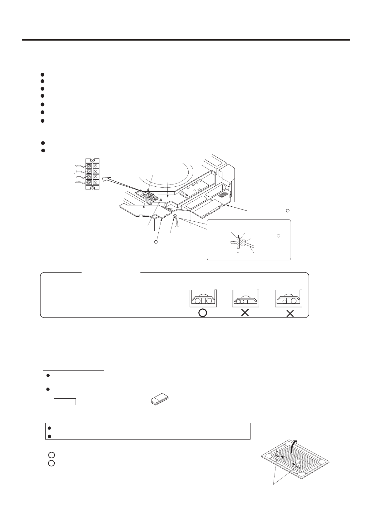
Connecting of unit
Remove cover of switch box (1) , drag wires into rubber tube A, then, after proper wiring with other wires,
tighten clamp A. Connect wires of correct pole to the terminal block inside.
Wind seal (12) around wires. (Be sure to do that, or, dew may occur).
Upon connecting, replace control box cover (1) and (2).
Connect with
outdoor unit
<<WARNING>>
Obscrve the following when connecting power supply terminal block:
Don't connect wires of different specifications to the same
terminal block.
(Loose wire may cause overheating of circuit)
Connect wires of same specifications as shown in right Fig.
Terminal block
Grounding lead
Cover of control box
Terminal block
Clip A
Rubber tube A
1
•
Don't fail to seal it, or, water may come in.
Connect wires of the same
specifications at two sides.
Cover of control box
Rubber tube
Attach seal pad
Don't connect wires of the
same specifications at one side.
Note: Have it sealed, leaving no space.
Seal pad (small size)( )
(Wind around wire)
In
Out
Field wiring
12
Don't connect wires of the
different specifications.
5.1.3.8 Wiring example
As for outdoor unit circuit, please see Installation Manual of outdoor unit.
Note: All electric wires have their own poles, poles must match that on terminal block.
2
5.1.3.9 Installation of ornament panel
Cautions for the installation
Be sure to show customers Operation Manual and guide them how to operate unit correctly. Before installation, read also
the Installation Manual of indoor unit.
With this ornament , 2 or 3 air flow direction is not available. Suitable height is 3 m.
Accessory
Pad
Pad
1. Prepare ornament panel
Handling of ornament panel
Ornament panel shall not be placed face down or against wall, neither on an uneven object.
Don' t bend carelessly the swing flap, or, problem may occur.
(1)
Remove air inlet grill from ornament panel:
1
Push in the bar on inlet grill and lift it up. (Refer to Fig. 1)
2
Lift it up for about 45 degree and remove it from ornament.
Tear off adhesive tape fixing air filter on the back of the air
inlet grill. (Refer to Fig. 2)
Bar
- 24 -
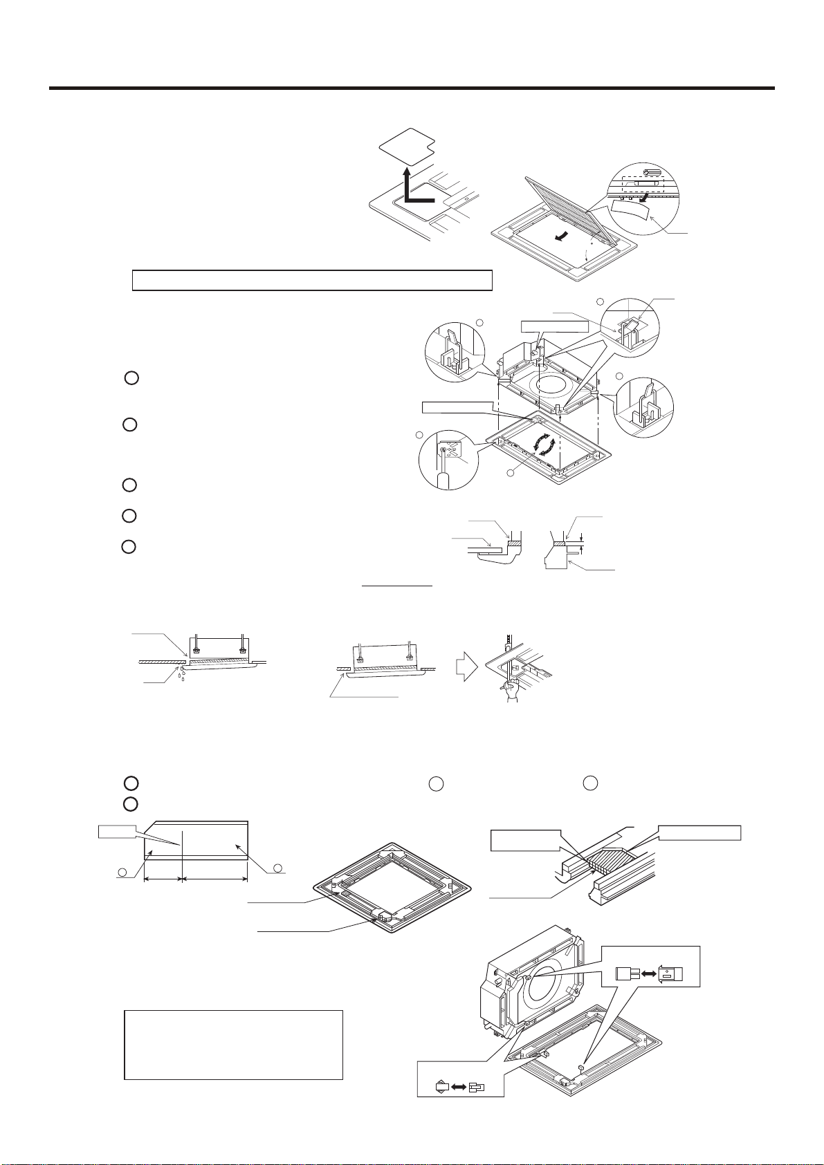
(2)
Remove cover plate at corner
Tear off the adhesive tape,
and slide it off.
(Refer to Fig. 3)
2. Install ornament panel on indoor unit.
For indoor unit installation, please refer to Installation Manual.
(1)
As shown in Fig . 7, match the position of
swing flap motor with that of the indoor unit
piping hole , so that ormament panel can be
placed on to indoor unit.
(2)
Installation of ornament panel
1
Place the holding ring on swing flao motor
side teporarily on hooks of the indoor unit.
(2 pcs)
Put the other two holding rings on the hooks at
2
both side of the indoor unit. (Care should be
taken not to push wiring of swing flap motor
into seals).
Screw in all 4 screws under holding ring for
3
about 15mm. (Pancl will rise).
Adjust the ornament panel as per Fig. 7 to
4
cover opening on the ceiling.
Tighten screws to redrce the thickness of seals
5
between ornament and indoor unit to 5-
8mm.
If screws are not tighten tight, problems in Fig, 8
might occur. Tighten screws properly.
Gas leakage.
Gas leakage from roof.
If there are still space after tightening
of screws, please readjust the height
of indoor unit. (Refer to Fig. 9)
Slide
Fig. 3
Swing flap motor
3
Ceiling material
Caution
INSTALLATION INSTRUCTIONS
Adhesive tape
45
Fig. 2
Hook
2
2
Indoor unit
Holding ring
Piping hole position
4
1
Fig. 7
Seal
5 _ 8mm
Ornament panel
If indoor unit is at horizontal level
and water drainage is smooth,
then, indoor unit height can be adjusted throrgh holes at corners of
ornament panel.
Contamination
Mist exists and drop down.
Fig. 8
Leave no space.
Fig. 9
3. Mounting on high ceiling
(1) Ornament panel can be mounted on ceiling as high as 3 m.
(2) Please install pad as accessary.
Cut open the pad along cutting ling. Use part a only and discard part b . (Refer to Fig. 4)
1
Install part a of the pad on the place shown in Fig. 5. Refer to Fig. 6.
2
Cutting line
a
50
100
Fig. 4
(3)Wiring on ornament panel
Connecting of wiring of the swing
flap motor on ornament panel. (2 places)
(Refer to Fit . 10)
If connecting is not made, error code
(A7) appears on remote controller. So,
make proper connecting.
b
Part a of the pad
Swing flap motor
Fig. 5
Side of indoor unit
Place it on the frame.
Part a of the pad
Leave no space.
Fig. 6
Side of ornament panel
Fig. 10
Wiring diagram
- 25 -
 Loading...