

Page 1
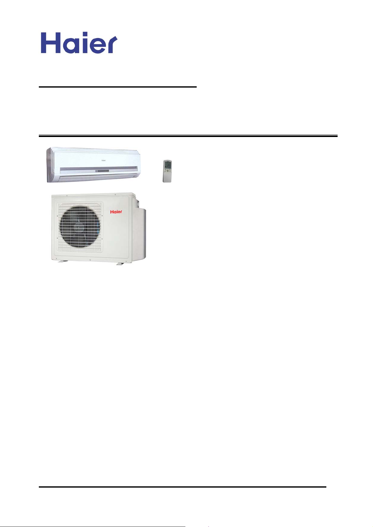
Commercial Air Conditioning
SERVICE MANUAL
Models
AS072XVERA
AS092XVERA
AS122XVERA
AU182XFERA
AU222XFERA
Features
High energy efficiency
Newly designed V-appearance for wall mounted unit, step or stepless air flow
control
New outdoor unit with valve cover plate, also the grille is changed from metal
one to plastic one
Adjustable heating temperature compenstation
Free combination, multiple connection types with different types of indoor
unit, total indoor load can be up to 135% than the standard match
Infrared control type
Central control and full automation, if connected with a central controller
New friendly refrigerant R410a, zero ODP, environment protection
Advanced technology, DC inverter control function
Health airflow and sterilize function for wall mounted unit, more healthy
Weekly timer (standard)
Group control function
Auto restart function
Low ambient temperature heating (-15 degree) function
Room card function
Manual code: SYJS-013-05REV.3
Edition: 2007-04-14
Page 2
Commercial Air Conditioner Model: AU18/222XFERA
AS072/092/122XVERA
CONTENTS
Contents………………………………………………………....2
1. Description of products & features………………………...3
2. Specification………………………………………………….6
3. Safety precaution……………………………………………
10
4. Net dimension of indoor and outdoor……………………..12
5. Installation instructions………..……………………………1
6. Parts and functions………………………….………………3
7. Remote controller YR-H65...……………………………….3
3
6
7
8. Refrigerant diagram…………………………………………45
9. Electrical control functions………………………………….4
10. Diagnostic information and trouble shooting...………….5
11. Electrical data………………………………………………6
12. Performance curves.......................................................7
13. Noise level.....................................................................7
14. Air velocity distribution...................................................7
7
9
5
1
5
8
-2-
Page 3
Commercial Air Conditioner Model: AU18/222XFERA
AS072/092/122XVERA
1.Description of products & features
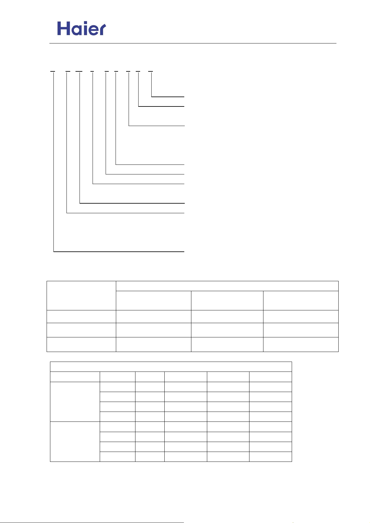
1.1. Products code explanation
U 18 2 X F E R A
A
Climate type: T1 (see table 1)
Design number (R stands for design sequence, DC inverter
type)
Product type: A stands for heat pump type, refrigerant is R22
B stands for heat pump type, refrigerant is R407C
E stands for heat pump type, refrigerant is R410A
N stands for cool only type, refrigerant is R407C
Appearance character
Product series: X stands for multi-split series
Applicable voltage: 2 stands for 220-230V/50Hz,
4 stands for 220V/60Hz,N stand for 380-400V/50Hz
Cooling / Heating capacity,18=18000BTU/h
Product type : “B” stands for cassette type, “C” stands for
convertible type, ”D” stands for duct, “S” stands for wall
mounted type, "E" stands for ceiling concealed type, “U”
stands for outdoor unit
Air Conditioner
1.2 Brief Introduction for T1、T2、T3 working condition
Climate type
Type of Air
Conditioner
Cooling Only
Heat pump
Electricity Heating
T1 T2 T3
18 ℃~43℃ 10℃~35℃ 21℃~52℃
-7℃~43℃ -7℃~35℃ -7℃~52℃
~43℃ ~35℃ ~52℃
1.3 Operating Range of Air Conditioners
Working temperature range
Rated Maximum Minimum
Cooling
Heating
Indoor
outdoor
Indoor
outdoor
DB℃
WB℃
DB℃
WB℃
DB℃
WB℃
DB℃
WB℃
27 32 18
19 23 14
35 43 10
24 26 6
20 27 15
14.5 -- --
7 24 -15
6 18 --
-3-
Page 4
Commercial Air Conditioner Model: AU18/222XFERA
AS072/092/122XVERA
1.4 Product features
High efficienct, universal outdoor unit
The outdoor unit can match with wall mounted type, duct and cassette type indoor unit. One set
outdoor can match with multiple indoor units, up to 3 sets. Even when you have already installed
the air conditioner, if you want to add or reduce one unit, go ahead freely as long as your operation
complies with our design. Greatly convenient for designer and installer.
Total indoor load can be up to 135% than the standard match
The total capacity of all indoor units can be 135% more than the mominal cooling capacity, but the
total indoor cooling capacity will not be increased.
Newly designed V- appearance indoor unit
The wall mounted type indoor unit adopts the newly designed V appearance, more fashion, more
beautiful. The unit is designed with the health airflow and sterilize function, which will make the air
more healthy. Also the air blow direction can be set as step or stepless control, much convenient to
control.
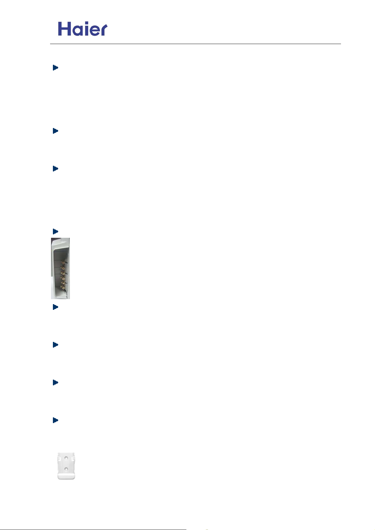
Newly designed guarding plate of valve
In order to protect the valve against the dust, the rain or the snow, etc. we add a
guarding plate to the valve.
Adopt the much friendlier refrigerant R410a
The air conditioner system adopts the greatly friendly refrigerant R410a, which is protective for the
ozone layer and is good to avoid the earth getting warmer. Benefit for the environment.
Adopt the advanced DC inverter technology
The system adopts the advanced DC inverter technology, which can consume less power energy to
realize the equal efficiency, saving money for you.
With air inlet filter, enhance the air quality
The high efficiency filter can collect the dirt and remove the bacterium, which can be installed on the
easy-to-unload place, convenient to be cleaned.
Convenient infrared remote controller
This remote controller YR-H65 can realize the healthy air flow and sterilize function, it is mobile type
appearance, so smart and compact.
And the infrared controller can be equipped with the controller holder, convenient to fix
the remote controller.
-4-
Page 5
Commercial Air Conditioner Model: AU18/222XFERA
AS072/092/122XVERA
Auto–restart function (optional)
All indoor units have auto-restart function. When the power supply cut off suddenly, the unit will
automatically recover the previous running mode once the power supply is on.
Self-diagnostic function
In the course of operation, if the failure occurs, the failure code will display on the wired controller or
on the operation panel. Then according to the failure code chart, you can eliminate the failure soon.
Central control function, if connected with a detector and a central controller
That is convenient for building management.
Weekly timing function, if connected with a detector and a weekly timer
Adjustable heating temperature compensation
In heating mode, the temperature compensation can be adjusted by the remote controller. If you do
not want the compensation, you can set the compensation as 0 degree.
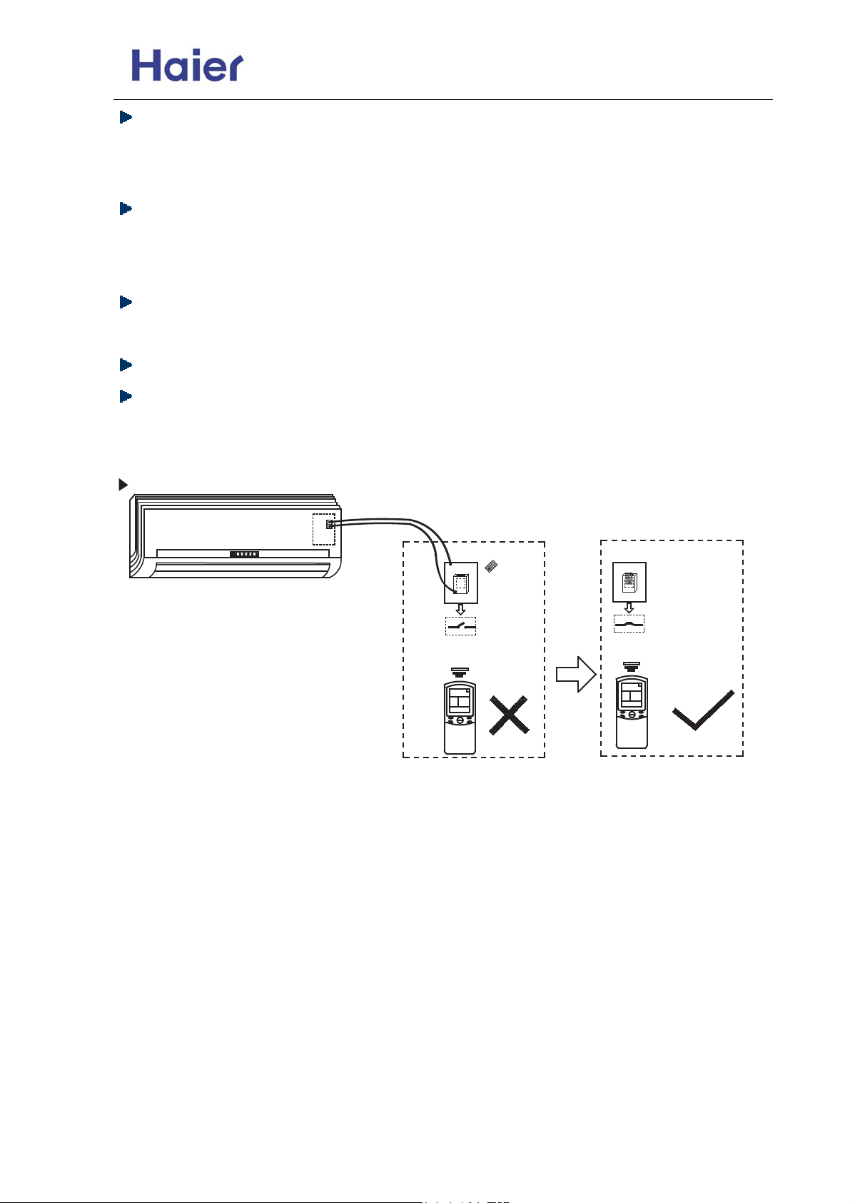
When room card function is available,indoor will be controlled as below figure:
ON
ON
OFF
OFF
When room card is disconnected
When room card is connected
-5-
Page 6
Commercial Air Conditioner Model: AU18/222XFERA
AS072/092/122XVERA
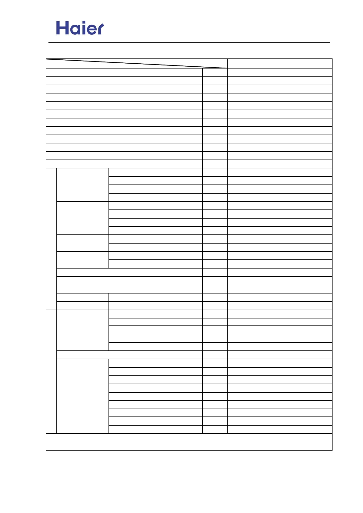
2. Specification
Item Model AU182XFERA
Function
Rating capacity
Power input
EER / COP
Minimum capacity
Power input
Maximum capacity
Power input
Power source
Max.Running current
Power facor(under rating power input)
Fuse size (recommended size)
Compressor
Fan
Heat exchanger
Outdoor unit
Dimension
(L×W×H)
Refrigerant control method
Defrosting method
Crankcase heater power
Noise level H/M/L dB(A)
Weight Net / Shipping kg / kg
Refrigerant R410A / 2.0
Pipe 3* Φ6.35
Connecting method
Between I.D &O.D
Piping
1. The above performance data are from the combination of AU182XFERA+2*AS092XVERA+AS122XVERA.
2. Large drop and long piping installation will obviously reduce the totao capacity.
Model / Manufacture ——
Oil charge and type ——
Type ——
Number ——
Type × Number ——
Speed r/min
Motor output power W
Air-flows (H/M/L) m³/h
Type / Diameter mm
Face area m²
External mm
Package mm
Type / Charge kg
No need to recharge m
Recharge g/m
Liquid mm
Gas mm
Drop between IU & OU
Piping length between IU & OU
Total liquid piping length
Drop between indoor units m
Max.Drop between IU & OU m
Max.Drop between IU & OU m
Max.Drop between indoor units m
Max.Piping length between IU & m
Max.Total liquid piping length
——
W 5300 7000
W 1650 1800
W/W
W 1500 1800
W 500 500
W
W
——
A / A 10.2 10.2
—— 99% 99%
A
——
——
W
——
m
m
m
m
Cooling Heating
3.21 3.88
5800 7400
2300 2300
1PH, 220-230V~, 50Hz
25
TNB175FLBM1 / MISTUBISHI ELEC.
670CC, MEL 56
Twin Rotary (DC inverter)
1
Axial × 1
850/ 700/ 500
35
about 3000
TP2M / 7.0
about 0.52
928/288/680
1015/405/760
PMV
Automatic by reversible cycle
35
51/-/-
54 / 60
30
20
3* Φ9.52
Flared
≤5
≤10
≤30
≤1
10(indoor unit lower than outdoor unit)
15 (indoor unit higher than outdoor unit)
5
25
45
-6-
Page 7
Commercial Air Conditioner Model: AU18/222XFERA
AS072/092/122XVERA
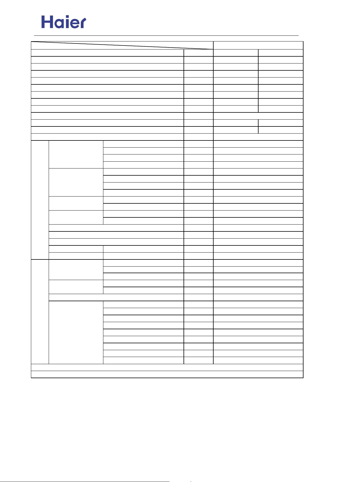
Item Model AU222XFERA
Function
Rating capacity
Power input
Current input
EER / COP
Minimum capacity
Power input
Maximum capacity
Power input
Power source
Max.Running current
Power facor(under rating power input)
Fuse size (recommended size)
Compressor
Fan
Heat exchanger TP2M / 7.0
Outdoor unit
Dimension
(L×W×H)
Refrigerant control method PMV
Defrosting method
Crankcase heater power 35
Noise level H/M/L dB(A)
Weight Net / Shipping kg / kg
Refrigerant R410A / 2.0
Pipe 3* Φ6.35
Connecting method
Between I.D &O.D
Piping
1. The above performance data are from the combination of AU222XFERA+AS092XVERA+2*AS122XVERA.
2. Large drop and long piping installation will obviously reduce the total capacity.
Model / Manufacture ——
Oil charge and type ——
Type ——
Number ——
Type × Number ——
Speed r/min
Motor output power W
Air-flows (H/M/L) m³/h
Type / Diameter mm
Face area m²
External mm
Package mm
Type / Charge kg
No need to recharge m
Recharge g/m
Liquid mm
Gas mm
Drop between IU & OU
Piping length between IU & OU
Total liquid piping length
Drop between indoor units m
Max.Drop between IU & OU m
Max.Drop between IU & OU m
Max.Drop between indoor units m
Max.Piping length between IU & m
Max.Total liquid piping length
——
W 6400 7300
W 2100 2000
A 9.3 8.9
W/W
W 1500 1800
W 500 500
W
W
——
A / A 12.9 12.9
—— 99% 99%
A
——
——
W
——
m
m
m
m
Cooling Heating
3.04 3.65
6800 7500
2900 2900
1PH, 220-230V~, 50Hz
25
TNB175FLBM1 / MISTUBISHI
670CC, MEL 56
Twin Rotary (DC inverter)
1
Axial × 1
960/ 700/ 500
35
about 3200
about 0.52
928/288/680
1015/405/760
Automatic by reversible cycle
55/-/-
54 / 60
30
20
3* Φ9.52
Flared
≤5
≤10
≤30
≤1
10(indoor unit lower than outdoor unit)
15 (indoor unit higher than outdoor
5
25
45
-7-
Page 8
Commercial Air Conditioner Model: AU18/222XFERA
AS072/092/122XVERA
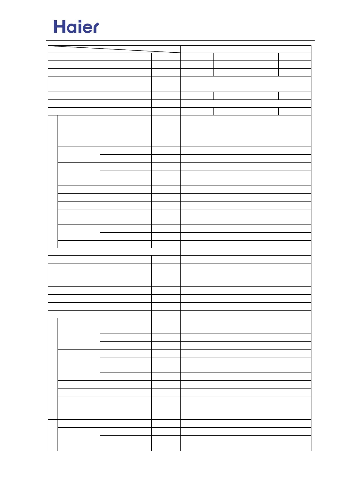
Item Model
Function
Capacity
Capacity
Power cable
Communication cable
Dehumidifying capacity
Power source
Running current
Fan CROSS×1
Heat exchanger TP2M / 7×0.35
Dimension
(L×W×H)
Drainage pipe material, diameter mm
Controller type
Refrigerant control
Noise level H/M/L dB(A)
Weight Net / Shipping kg / kg
Refrigerant
Pipe 6.35 6.35
Piping
Connecting method
Item
Function
Capacity
Capacity
Dehumidifying capacity
Power cable
Communication cable
Power source
Running current
Fan
Heat exchanger TP2M / 7×0.35
Dimension
(L×W×H)
Drainage pipe material, diameter mm
Controller type
Refrigerant control
Noise level H/M/L dB(A)
Weight Net / Shipping kg / kg
Refrigerant
Pipe
Piping
Connecting method
Type × Number ——
Speed r/min
Motor output power W
Air-flows (H/M/L) m³/h
Type / Diameter mm
Total area m²
External mm
Package mm
Type ——
Liquid mm
Gas mm
Type × Number ——
Speed r/min
Motor output power W
Air-flows (H-M-L) m³/h
Type / Diameter mm
Total area m²
External mm
Package mm
Type ——
Liquid mm
Gas mm
——
BTU/h
W
——
——
10‐³×m³/h
N, V, Hz
A / A 0.15 0.15 0.15 0.15
——
——
——
——
BTU/h
W
10‐³×m³/h
——
——
N, V, Hz
A / A
——
——
——
AS072XVERA AS092XVERA
Cooling Heating Cooling Heating
7000 8000 9000 10000
2000 2300 2500 2900
3 × (1.0~1.5mm2 )
2x(0.75~1.25mm2 ), must be shielded
1.0 / 1.0 /
1,220-230~, 50
1150/1050/950 1200/1100/1000
27 27
480/430/380
about 0.15 about 0.15
795*197*265
880×315×330 880×315×330
PVC, 11.4/16.4
Infrared (YR-H65)
PMV on outdoor unit
36/33/30 38/34/31
7.6/10.6 7.6/10.6
R410A R410A
9.52 9.52
Flared
AS122XVERA
Cooling
11000
3200
1.6
3 × (1.0~1.5mm2 )
2x(0.75~1.25mm2 ), must be shielded
1, 220~230, 50
0.15 0.15
CROSS×1
1250/1150/1050
27
550/480/430
about 0.20
795×197×265
880×315×330
PVC, 11.4/16.4
Infrared (YR-H65)
PMV on outdoor unit
39/36/33
7.6/10.6
R410A
6.35
9.52
Flared
CROSS×1
520/450/390
795×197×265
Flared
Heating
13000
3800
/
-8-
Page 9
Commercial Air Conditioner Model: AU18/222XFERA
AS072/092/122XVERA
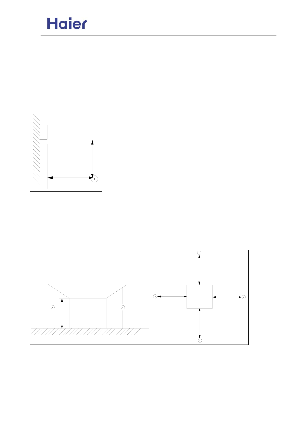
Norminal condition: indoor temperature (cooling): 27℃DB/19℃WB, indoor temperature (heating): 20℃
DB
Outdoor temperature(cooling): 35℃DB/24℃WB, outdoor temperature(heating): 7℃DB/6℃WB
The noise level will be measured in the third octave band limited values, using a Real Time Analyser
calibrated sound intensity meter. It is a sound pressure noise level. The detailed method please refer to
the following information:
Installation state: the unit should be placed on the flat floor or be mounted in horizontal direction.
Testing method:
mounting-on-wall unit:
0.8m
outdoor unit:
1.air outlet from side: the noise level is the average sound pressure level measured from front, left, right
directions.
2.air outlet from top: the noise level is the average sound pressure level measured from front, back, left, right
directions.
measured point:
H ( height to the ground) = (h (unit height) + 1m) /2
and, it is 1m to each side.
1m
1m
1m
1m
h
Note: ⊙ is the real time analyser position
1m
-9-
Page 10
Commercial Air Conditioner Model: AU18/222XFERA
AS072/092/122XVERA
3. Safety precaution
Carefully read the following information in order to operate the airconditioner correctly .
Below are listed three kinds of Safety Cautions and Suggestions.
WARNING!
CAUTION!
INSTRUCTIONS: These information can ensure the correct operation of the machine.
Be sure to conform with the following important Safety Cautions.
The Safety Cautions should be at hand so that they can be checked at any time when needed.
If the conditioner is transferred to the new user, this manual should be as well transferred to the new user.
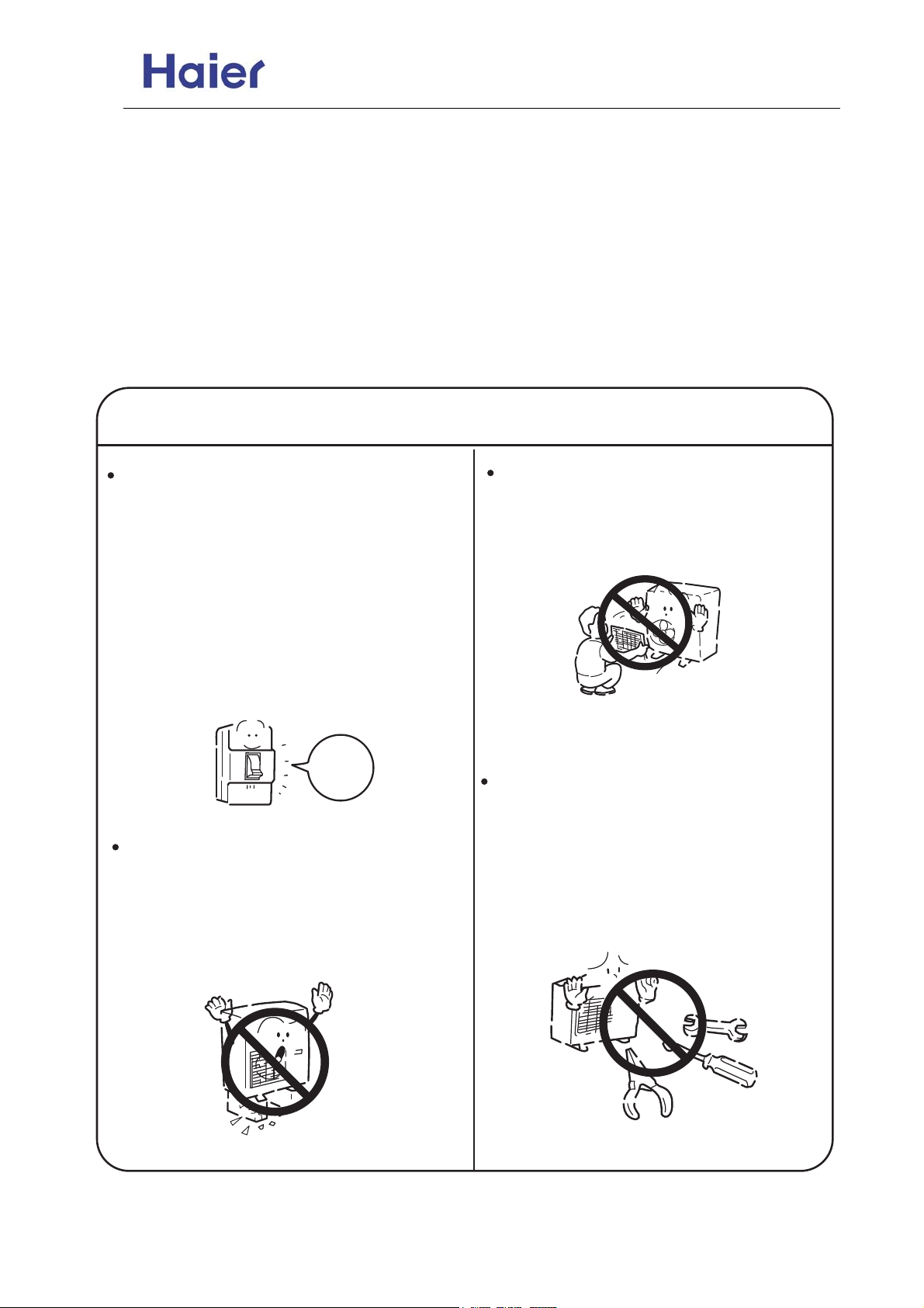
If any abnormal phenomena is found
(e. g.smell of firing), please cut off the
power supply immediately , and contact
the dealer to find out the handling
method.
In such case, to continue using the
conditioner will damage the conditioner,
and may cause electrical shock or fire
hazard.
Incorrect operations may result in severe consequences of death or serious injuries.
Incorrect operations may result in injuries or machine damages; in some cases may
cause serious consequences.
WARNING!
Don't dismantle the outlet of the
outdoor unit.
The exposed fan is very dangerous
which may harm human beings.
switch
After the unit being used for a long time,
the base should be checked for any
damages.
If the damaged base is not repaired, the
unit may fall down and cause accidents.
off
When the unit needs maintenance and
repairment, please call dealer to handle it.
Incorrect maintenance and repairment
may cause water leak, electrical shock
and fire hazard.
-10-
Page 11
Commercial Air Conditioner Model: AU18/222XFERA
AS072/092/122XVERA
WARNING!
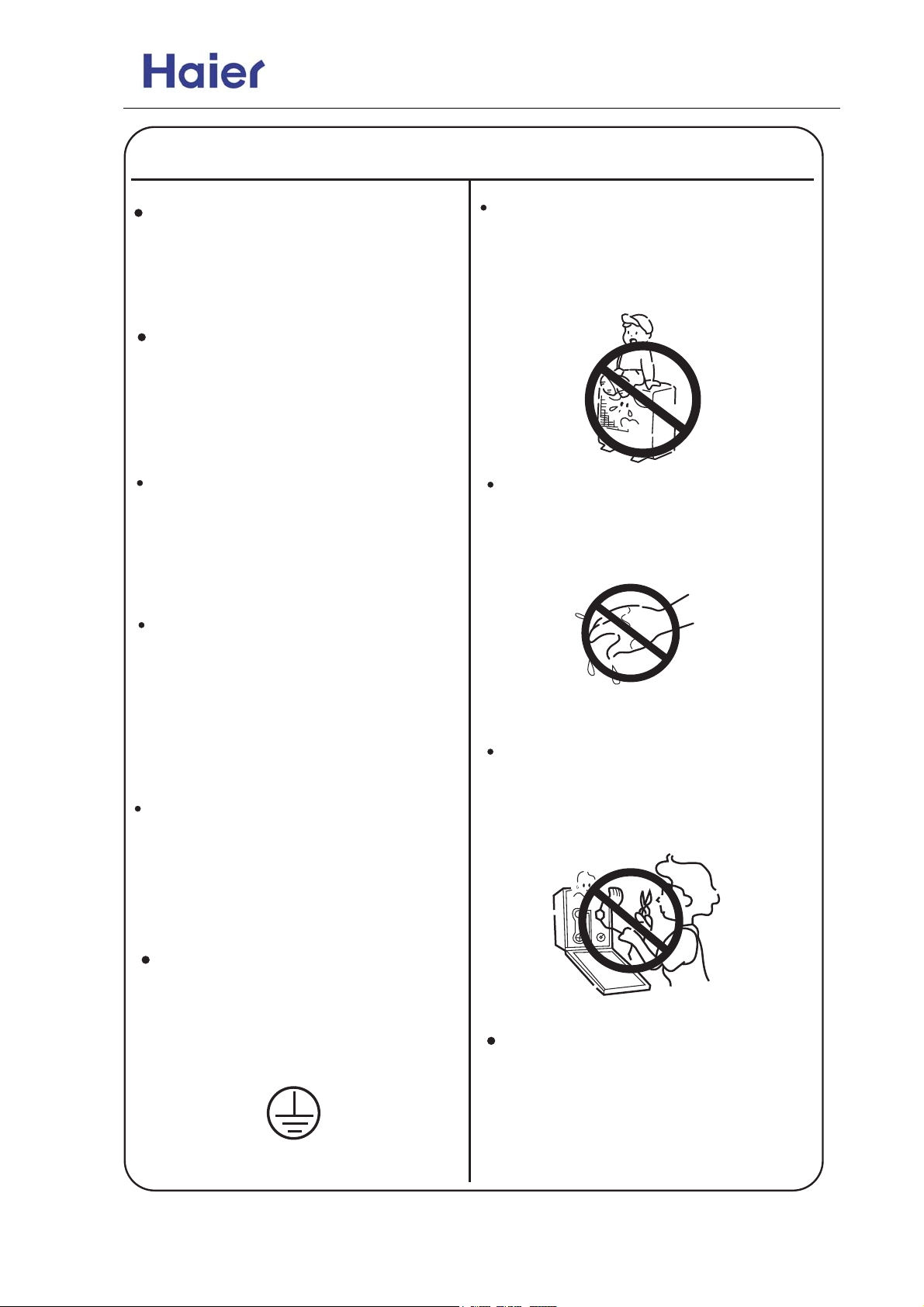
Installed electrical-leaking circuit
breaker .
Nothing or nobody is permitted to
placed on or stand on outdoor unit.
It easily cause electrical shock without
circuit breaker.
The falling of goods and people may
cause accidents.
Air-conditioner can't be installed in
the environment with inflammable
gases because the inflammable gases
near to air-conditioner may cause fire
hazard.
Please let the dealer be responsible for
installing the conditioner .
Don't operate the air-conditioner with
damp hands.
Incorrect installation may cause water
leak, electrical shock and fire hazard.
Otherwise will be shocked.
Call the dealer to take measures to
prevent the refrigerant from leaking.
If conditioner is installed in a small
room be sure to take every measure in
order to prevent suffocation accident
even in case of refrigerant leakage.
When conditioner is removed or
reinstalled, dealer should be responsible
for them.
Incorrect installation may cause water
leaking, electrical shock and fire hazard.
Only use correctly-typed fuse.
May not use wire or any other materials
replacing fuse, other-wise may cause
faults or fire accidents.
Connect earthing wire.
Earthing wire should not be connected to the gas pipe, water pipe,
lightning rod or phone line, in-correct
earthing may cause shock.
Earthing
Use discharge pipe correctly to ensure
efficient discharge.
Incorrect pipe use may cause water
leaking.
-11-
Page 12
Commercial Air Conditioner Model: AU18/222XFERA
AS072/092/122XVERA
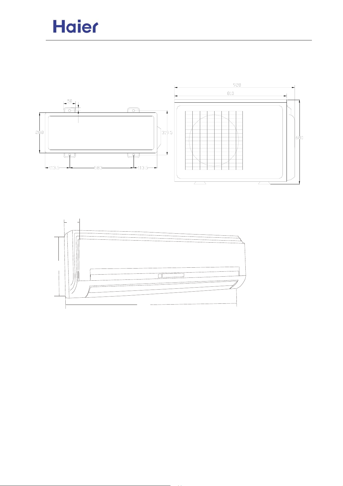
4. Net dimension of indoor and outdoor
AU18/222XFERA:
37,1-85463
18
Wall mounted unit:
305
225
870
-12-
Page 13
Commercial Air Conditioner Model: AU18/222XFERA
AS072/092/122XVERA
5. Installation Instructions
■R410A
The working pressure of R410A is approximately 1.6 times higher than R22. Because the oil in the
refrigerant is different, please do not mix them.
Refrigerant R22 (single) R410A (mixed) R407C (mixed)
Oil Mineral oil (SONTEX 200LT) Synthetic oil (POE oil) Synthetic oil (POE oil)
Pressure ratio 1 Approx. 1.6 Approx. 1.1
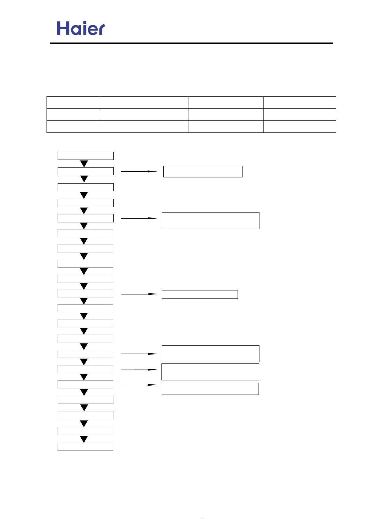
■Operation flow
prepare work schedule
refrigerant inspection
operation chart preparation
indoor unit installation
refrigerant piping work
drain piping work
duct work
insulation work
remote controller installation
electric wiring work
outdoor unit foundation work
outdoor unit installation
refrigerant piping connection
leakage test
evacuation and drying
additional refrigerant charging
gas leakage check
maintenance panel installation
trial running and adjustment
hand over
1. Always inspect the used refrigerant
2. Always use the specified refrigerant
1. Use piping material of the specified thickness
2. Do not use dirty pipe
3. Always flow nitrogen during welding work
1. Do not connect the power supply
1. Charge the nitrogen to the set pressure
2. 24 hours later,check if the pressure in the pipe
has reduced
1. Air purging by refrigerant is prohibited seriously
2. Use a special vacuum pump with reverse check
mechanism
1. Calculate the refrigerant additional charging
amount, and charge a suitable amount.
-13-
Page 14
Commercial Air Conditioner Model: AU18/222XFERA
AS072/092/122XVERA
■Piping material
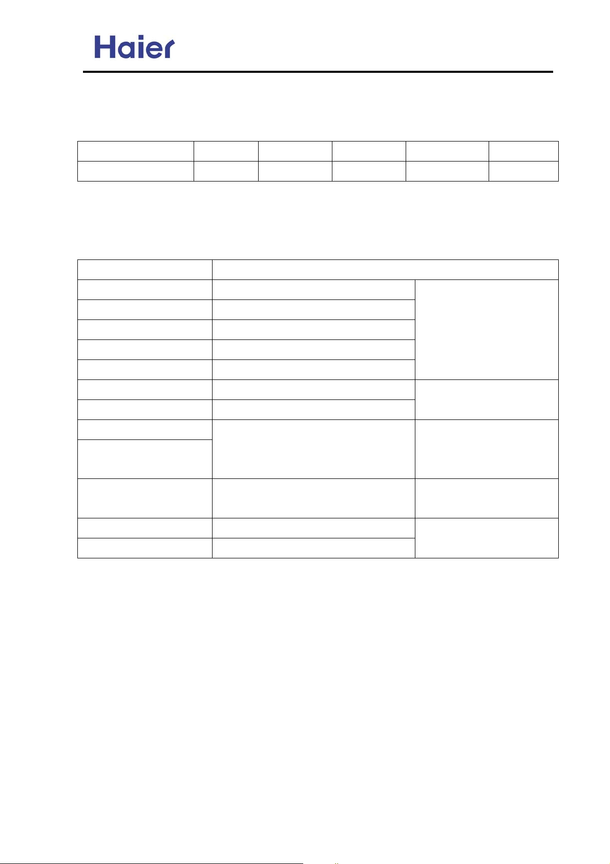
1. Use the correct refrigerant piping and materials for R410A
2. For the pipe wall thickness, see the table below:
Pipe diameter Φ6.35 Φ9.52 Φ12.7 Φ15.88 Φ19.1
Pipe wall thickness 0.8 0.8 0.8 1.0 1.2
Note: Always observe and comply with the local regulations when installing the refrigerant piping.
■Tools
R410A work requires a number of special tools (* symbol). Since the tools used in R22 work
cannot be used for R410A, provide the tools separately.
Tool name Process and application
Pipe cutter Piping cutting
*Flaring tool Pipe flaring work
*Torque wrench Flare nut connection
Expander Expansion at pipe connection
Pipe bender Pipe bending work
Nitrogen gas Pipe oxidation prevention
Welder Pipe brazing
*Gauge manifold
*Charging hose
*Vacuum pump (with
adapter)
Electronic scale
Gas leakage detector Gas leakage test
Vacuum evacuation and refrigerant
charging operation check
Vacuum drying
■Work precautions
Refrigerant piping work
Air tightness test
Air tightness test
Refrigerant additional
charging
Refrigerant additional
charging
Refrigerant check: Before work, check the used refrigerant and prepare materials matched to the
refrigerant.
Refrigerant piping: Observe the basics of refrigerant piping to avoid the unnecessary problems. In
addition, when performing the welding work, seal in the nitrogen gas to the pipes, and prevent it
from the oxidation.
Leak pressure detection: Perform seal detection and make sure there is no refrigerant leakage.
Vacuum drying: If the vacuum pump has not the reverse flow check mechanism, use the pump
together with a reverse flow check adapter.
Additional refrigerant: Charge a suitable amount of refrigerant with a special R410A gauge
manifold and charging hose.
-14-
Page 15

Commercial Air Conditioner Model: AU18/222XFERA
AS072/092/122XVERA
5.1 Outdoor Installation
Cautions
All electrical repairs must be carried out by qualified
electricians. Inadequate repairs may result in a major
source of danger for the user of the air conditoiner.
Do not damage any parts of the air conditioner that
carry refrigerant by piercing or perforating the air
conditioner's tubes with sharp or pointed items,
crushing or twisting any tubes, or scraping the
coatings off the surfaces. If the refrigerant spurts out
and gets into eyes, it may result in serious eye
injuries.
Do not obstruct or cover the ventilation grille of the
air conditioner. Do not put fingers or any other things
into the inlet/outlet and swing louver.
Do not allow children to play with the air conditioner.
In no case should children be allowed to sit on the
outdoor unit.
Specifications
2. If the supply cord is damaged, it must be replaced
by the manufacturer or its service agent or a similar
qualified person.
3. If the fuse on PC board is broken please change it
with the type of T 3.15A /250VAC or T 25A/250VAC.
Please check the circuit diagram about the fuse
replaced.
4. The wiring method should be in line with the local
wiring standard.
5. The power cable and connecting cable are self-
provided. The requirement of the power cable to the
outdoor unit: H05RN-F 3G 4.0mm
Model
AU182XFERA
AU222XFERA
Cable type
H05RN-F 3G 4.0mm
2
2
All the cables shall have got the Local authentication
certificate.
The refrigerating circuit is leak-proof.
6. The breaker of the air conditioner should be all-pole
The machine is adaptive in following
situation
1. Applicable ambient temperature range:
Maximum:D.B/W.B 32 C/23 C
Minimum:D.B/W.B 18 C/14 C
Maximum:D.B 43 C/26 C
Minimum:D.B
Maximum:D.B 27 C
Minimum:D.B 20 C
Maximum:D.B/W.B 24 C/18 C
Minimum:D.B/W.B -15 C
10 C/6 C
Cooling
Heating
Indoor
Outdoor
Indoor
Outdoor
switch; and the distance between its two contacts
should be no less 3mm. Such means for disconnection
must be incorporation in the fixed wiring.
7. The waste battery shall be disposed properly.
Safety precautions
To ensure proper installation, please read this safety precautions carefully before the installation. After
installation, start the unit correctly and ensure that you show the customer how to operate and maintain
the units.
WARNING!
CAUTION!
Incorrect operations may result in severe consequences of death or serious injuries.
Incorrect operations may result in injuries or machine damages; in some cases may
cause serious consequences.
-15-
Page 16
Commercial Air Conditioner Model: AU18/222XFERA
AS072/092/122XVERA
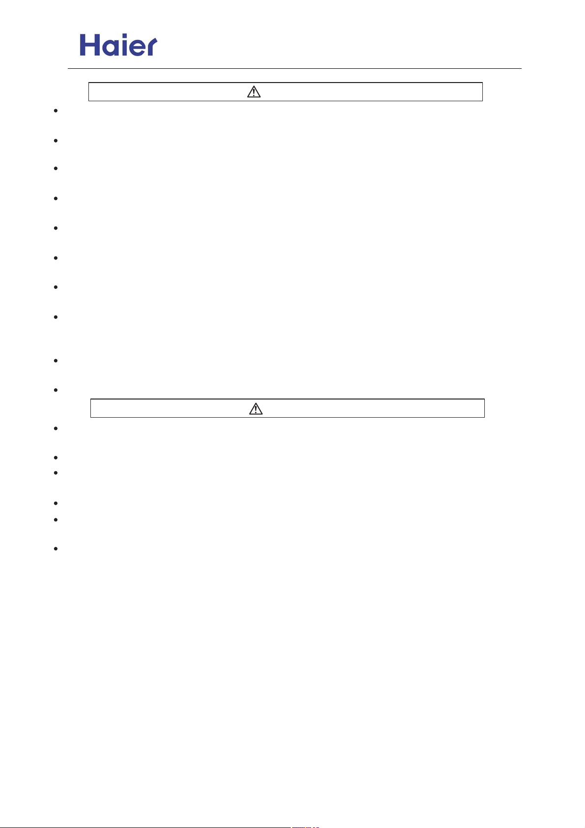
WARNING
Installation work must be carried out by professional qualified people, do not install the unit by
yourself. Incorrect installation will cause water leakage, electric shock and potentially fire.
Install the unit as per the manual. Incorrect installation will cause water leakage, electric
shock or fire risk.
Be sure to use specified accessories and parts. Otherwise, water leakage, electric shock, fire risk
or unit falling down may occur .
Mounting position must be strong enough to hold the unit. Or, the unit will potentially fall down
causing injuries.
When installing the unit, take in consideration storms and high winds. Incorrect installation may
cause the unit to fall down.
All electric work should be carried out by experienced personnel as per current regulations and
this manual. Incorrect installation or undersized electric cable may cause electric shock or fire risk.
All circuits must be earthed. Ensure that no external forces will affect the terminal block and electric
cable. Poor wiring and installation may cause fire risk.
Arrange wire connection between connecting the indoor and outdoor power supply correctly. Fix
terminal cover firmly to avoid overheating, electric shock or even fire risk.
In the case of a refrigerant leakage during unit installation, keep the room well ventilated.
Check the unit upon installation. Be sure there is no leakage. Refrigerant will induce a poisonous
gas subject to heat.
Isolate power supply before touching terminal block.
WARNING
All units shall be earthed. The earth must not be connected to a gas pipe, water pipe, or telephone
line. Poor earthing could cause electric shock.
Be sure to install a circuit breaker to avoid electric shock.
Arrange water drainage according to this manual. Cover pipe with insulation materials to prevent
condensation occuring. Improper installation of water drainage will cause water leakage.
To maintain good picture or reduce noise, keep the unit at least 1m from T.V. or radio,
when installing the communication wire and power supply. (If the radio wave is relatively strong,
1m is not enough to reduce the interference).
Do not install the unit in following places:
(a) Oil mist or oil gas exists, such as kitchen, or, plastic parts may age, or water leakage.
(b) Where there is corrosive gas. Copper tube and welded part may be damaged due to corrosion
causing leakage.
(c) Where there is strong radiation. It will affect the unit's control system, causing malfunction of
the unit.
(d) Where there are flammable gas, dirt, and volatile matter (thinner, gasoline) exist, these items
will cause a fire risk.
-16-
Page 17

Commercial Air Conditioner Model: AU18/222XFERA
AS072/092/122XVERA
Installation accessories
The following accessories are supplied together with the outdoor unit.
No.
1
2
3
Drawing
Name of parts
Drainage elbow
Rubber cushion
ClampClap
Quantity
1
4
1
Choose the installation place
Place, robust not causing vibration, where the body can be supported sufficiently.
Place, not affected by heat or steam generated in the vicinity, where inlet and outlet of the unit are not
disturbed.
Place, possible to drain easily, where piping can be connected with the outdoor.
Place,where cold air can be spread in a room entirely.
Place, nearby a power receptacle, with enough space around.(Refer to drawings).
Place, where the distance of more than 1m from televisions, radios, wireless apparatuses and fluorescent
lamps can be left.
In the case of fixing the remote controller on a wall, place where the indoor unit can receive signals when
the fluorescent lamps in the room are lightened.
-17-
Page 18

Commercial Air Conditioner Model: AU18/222XFERA
AS072/092/122XVERA
Installation drawings of indoor and outdoor units
1. Do not connect the embedded branch piping and the outdoor unit when only carrying out piping work
without connecting the indoor unit in ordor to add another indoor unit later. Make sure that no dirt or
mositure gets into eigher side of the embedded branch piping.
2.It is impossible to connect the indoor unit for one room only. Be sure to connect at least 2 rooms.
Arrangement of piping directions
Rear left
Rear right
Below
Attention must be
paid to the rising up
of drain hose
Right
More than 10cm
Wrap the insulation pipe with the
finishing tape from bottom to top.
More than 5cm
Left
Cut thermal insulation pipe to an
appropriate length and wrap it with
tape, making sure that no gap is left in
the insulation pipe's cut line.
more than 10cm
more than 10cm
more than 25cm
more than 60cm
If there is the danger of the unit failing or overturning, fix the unit with foundation bolts, or with wire or other
means.
If the location does not have good drainage, place the unit on a level mounting base(or a plastic pedestal).
Install the outdoor unit in a level position. Failure to do so may result in water leakage or accumulation.
-18-
Page 19

Commercial Air Conditioner Model: AU18/222XFERA
AS072/092/122XVERA
Power source
Before inserting power plug into receptacle, check the voltage without fail. The power source is the
same as the corresponded nameplate.
Install an exclusive branch circuit of the power.
A receptacle shall be set up in a distance where the power cable can be reached. Do not extend the
cable by cutting it.
Matching of the indoor and outdoor units
AU182XFERA
Combination
1:2
1:3
A
BC
07 12
09 09
09 12
12 12
07 07 07
07 07 09
07 07 12
07 09 09
07 09 12
09 09 09
09 09 12
Remark
*
*
*
AU222XFERA
Combination
1:2
1:3
A
07 1
09
09 1
1
07 07 09
07 07 12
07 09 09
07 09 12
09 09 09
09 09 12
09 12 12
BC
4
12
4
12
Remark
*
*
*
*
WARNING!
Combinations those marked * can not be applied where the temperature in winter is too low and in
summer is too higher to avoid bad heating or cooling effect.
Limitations on the installation
1.Precautions on installation
Check the strength and level of the installation ground so that unit will not cause any operating vibration
or noise after installation.
In accordance with the foundation drawing in fix the unit securely by means of the foundation bolts.
It is best to screw in the foundation bolts unit their length are 20 mm from the foundation surface.
2.Selecting a location for installation of the indoor units
The maxinum allowable length of refrigerant piping, and the maxmum allowable height
difference between the outdoor and indoor units, are listed below.
(The shorter the refrigerant piping, the better the performance. Connect so that the
piping is as short as possible. Shortest allowable length per room is 3m)
-19-
Page 20
Commercial Air Conditioner Model: AU18/222XFERA
AS072/092/122XVERA
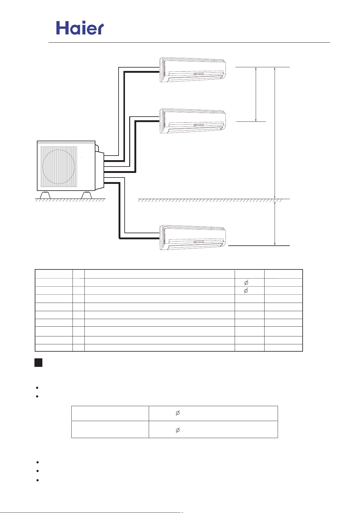
3. Limitations data on the piping work .
L1
A
h
L2
B
H +
L3
H -
C
The piping length information, please refer the following table.
Item
A, B, C liquid pipe
A, B, C Gas pipe
L1 (one way)
L2 (one way)
L3 (one way)
L1+L2+L3 m Total liquid piping length
h
H +
H -
Unit
Size of the liquid side connection pipe
mm
mm
Size of the gas side connection pipe
Pipe length when the compressor connects with two indoor units
m
m
Pipe length when the compressor connects with two indoor units
m
Pipe length when the compressor connects only one indoor unit
m
Drop between every two indoor units
m
Drop between the outdoor unit and the indoor unit
m
Drop between the outdoor unit and the indoor unit
Descriptions
Standard
6.35
9.52
*10
*10
*10
*30 *45
*1
*5
*5
Maximum
/
/
*30
*30
*30
*5
*15
*10
Refrigerant piping work
1. Selection of pipe
To this unit, both liquid and gas pipes shall be insulated as they become low temperature in operation.
Use optional parts for piping set or pipes covered with equivalent insulation material.
Liquid pipe
Gas pipe
6.35mm ( 1/4'' ) x 0.8mm
9.52mm ( 3/8'' ) x 0.8mm
2. Connection of pipe
Apply refrigerant oil on half union and flare nut.
To bend a pipe, give the roundness as large as possible not to crush the pipe.
Connecting the pipe of gas side firstly makes working easier.
-20-
Page 21

Commercial Air Conditioner Model: AU18/222XFERA
AS072/092/122XVERA
Flare nutHalf union
Torque wrenchSpanner
Forced fastening without careful centering may damage the threads
and cause a leakage of gas.
Pipe Diameter ( )
Liquid Side 6.35mm (1/4'')
Fastening Torque
18N.m
Gas Side 9.52mm (3/8'') 50N.m
3. Attaching Drain-Elbow
If the drain-elbow is used, please attach it as figure.
Hose
Drain elbow
4.Cutting and Flaring work of piping
Pipe cutting is carried out with a pipe cutter and burs must be removed.
After inserting the flare nut, flaring work is carried out.
A
Liquid side
Pipe diameter* Size A (mm)
6.35mm(1/4")
0.8~1.5
Gas side
9.52mm(3/8")
Flare tooling dia.
Correct
Lean
Damage of flare
Incorrect
Crack Partial
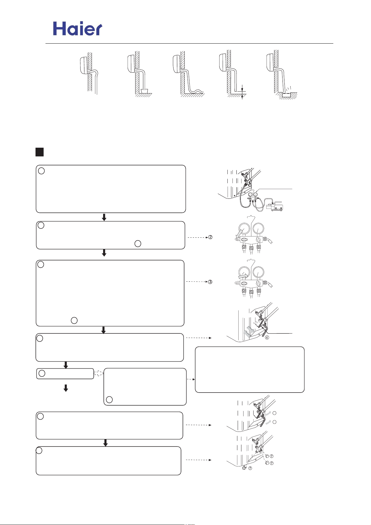
5.On drainage
Please install the drain hose so as to be downward slope without failure.
Please don't do the drainage as shown below.
-21-
1.0~1.5
Too outside
Page 22
Commercial Air Conditioner Model: AU18/222XFERA
AS072/092/122XVERA
Less than 5cm
It becomes high midway.
The end is immersed
in water
It waves. It gap with the
ground ts too small.
There is the bad
smell from a ditch.
Please pour water in the drain pan of the indoor unit, and confirm that drainage is carried out serely
to outdoor.
In case that the attached drain hose is in a room, please apply heat insulation to it without fail.
Purging method: to use vacuum pump
Liquid stop valve
1 .Detach the service port's cap of 3-way valve, the valve
rod's cap for 2-way valve and 3-way valves, connect the
service port into the projection of charge hose (low) for
gaugemanifold. Then connect the projection of charge
hose (center) for gaugemanifold into vacuum pump.
2 .Open the handle at low in gaugemanifold, operate
vacuum pump. If the scale-moves of gause (low) reach
vacuum condition in a moment, check 1 again.
3 .Vacuumize for over 15min. And check the level gauge
which should read -0.1MPa (-76 cm Hg) at low pressure
side. After the completion of vacuumizing, close the handle
'Lo' in the vacuum pump. Check the condition of the scale
and hold it for 1-2min. If the scale-moves back in spite of
tightening, make flaring work again, then return to the
beginning of 3 .
4 .Open the valve rod for the 2-way valve to and an angle
of anticlockwise 90 degree. After 6 seconds, close the 2-
way valve and make the inspection of gas leakge.
5 .No gas leakage?
In case of gas leakage, tighten
parts of pipe connection. If
leakage stops, then proceed
6 steps.
6 .Detach the charge hose from the service port, open
2-way valve and 3-way. Turn the valve rod anticlockwise
until hitting lightly.
7 .To prevent the gas leakage, turn the service ports cap,
the valve rodis cap for 2-way valve and 3-way's a little
more than the point where the torque increases suddenly.
2 way valve
3 way valve
Open
Close
2 way valve
If it does not stop gas leakage, discharge
whole refrigerants from the service port.
After flaring work again and vacuumize, fill
up prescribed refrigerant from the gas
cylinder.
2 way valve
3 way valve
2 way valve
3 way valve
Gas stop valve
Gauge maifold(R410A)
Vacuum pump(R410A)
3 way valve
0
90
90
Service port cap
Service port
0
for 6 sec.
6
6
Valve rod cap
Valve rod cap
-22-
Page 23
Commercial Air Conditioner Model: AU18/222XFERA
AS072/092/122XVERA
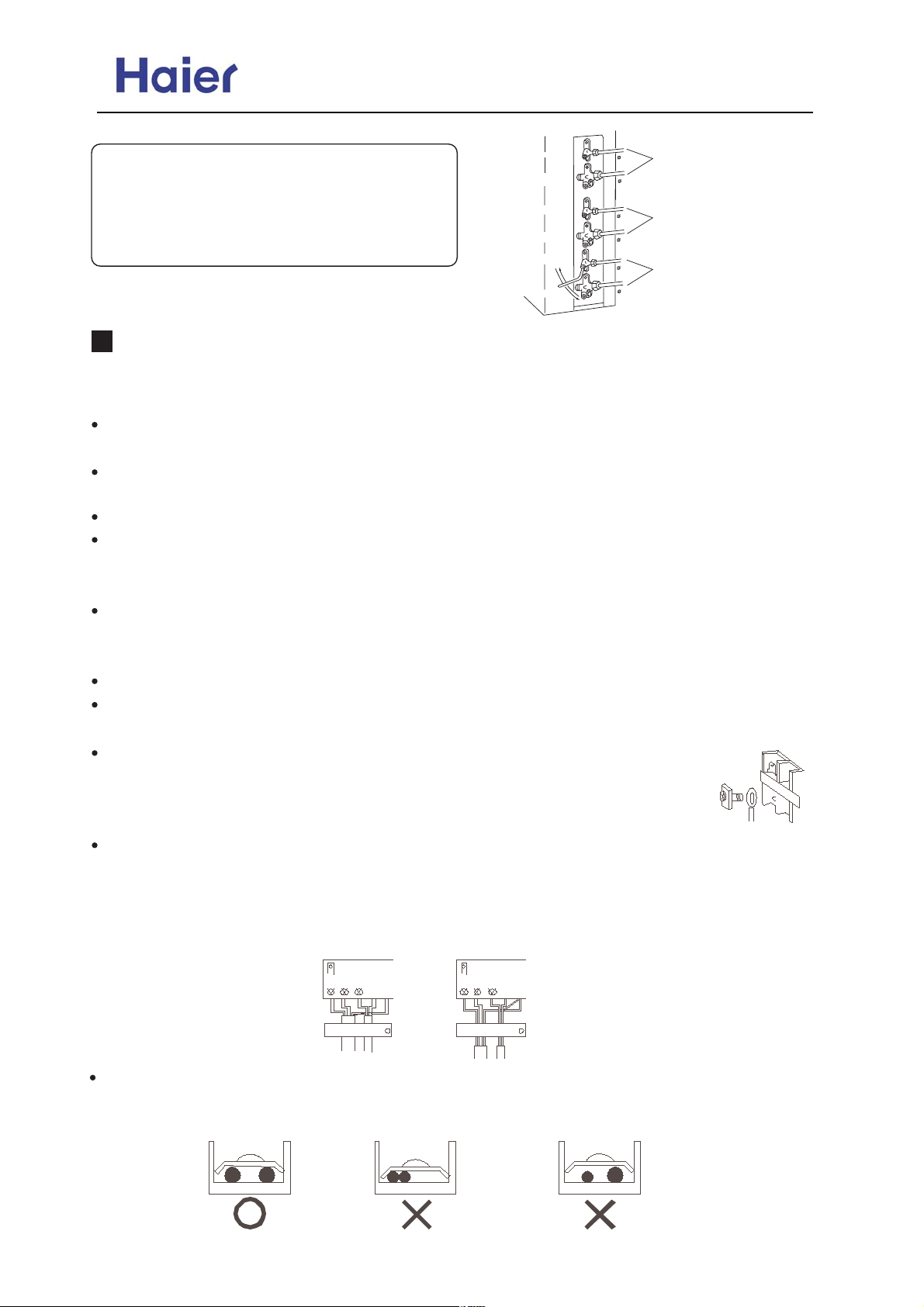
CAUTION:
If the refrigerant of the air conditioner leaks, it is necessary
to make all the refrigerant out. Vacuumize first, then charge
the liquid refrigerant into air conditioner according to the
amount marked on the nameplate.
2 way valve
3 way valve
2 way valve
3 way valve
2 way valve
o
90
10s
3 way valve
6.35mm
(1/4")
9.52mm
(3/8")
6.35mm
(1/4")
9.52mm
(3/8")
6.35mm
(1/4")
9.52mm
(3/8")
To indoor unit A
To indoor unit B
To indoor unit C
Wiring work
1. Electric wiring
Note:
The air conditioner must use special circuit , and wiring by the qualified electrician according to the
wiring rules specified in national standard.
The grounding wire and the neutral wire shall be strictly separated. Connect the neutral wire with
grounding wire is incorrect.
The electric leakage breaker must be installed.
All the electric wire must be copper wire.When wiring,there shall keep a proper distance between the
power line and communication wire to avoid twist together. Otherwise,signal disturbance will occur,and
the air conditioner can not operate normally. Power supply: 1PH, 220-230V~, 50Hz.
The wiring method of power line is Y connection. If the power line is damaged, in order to avoid
risk of electric shock, it must be replaced by the manufacturer or its repair center or other similar
qualified person.The connecting cable must be shielded.
Fuse: T3.15A 250VAC T25A 250VAC (Please check with the outdoor unit wiring diagram.)
Please check the circuit diagram about the fuse replaced.
2. Wiring method
Wiring method of ring terminals
For the connection wire with ring terminals, its wiring method is as shown in
the right figure: remove the connecting screw, put the screw through the ring on the
end of the wire, then connect to the terminal block and fasten screw.
Wiring method of straight terminals
For the connection wire without orbicular terminals, its wiring method is: loosen
the connection screw, and insert the end of the connection wire completely into the Terminal block,
then fasten the screw. Slightly pull the wire outwards to confirm it is firmly held.
Wiring Method for
Ring Terminal Block
Correct Pressing
Wrong Pressing
Terminal
block
Pressing
Clamps
Crimp connection method for wires without terminals
Connect the wire with
same diameter to the
two sides of the terminal
Do not connect the
wire with same diameter
to the same side
-23-
Do not connect the
wire with different
diameters
Page 24
Commercial Air Conditioner Model: AU18/222XFERA
AS072/092/122XVERA
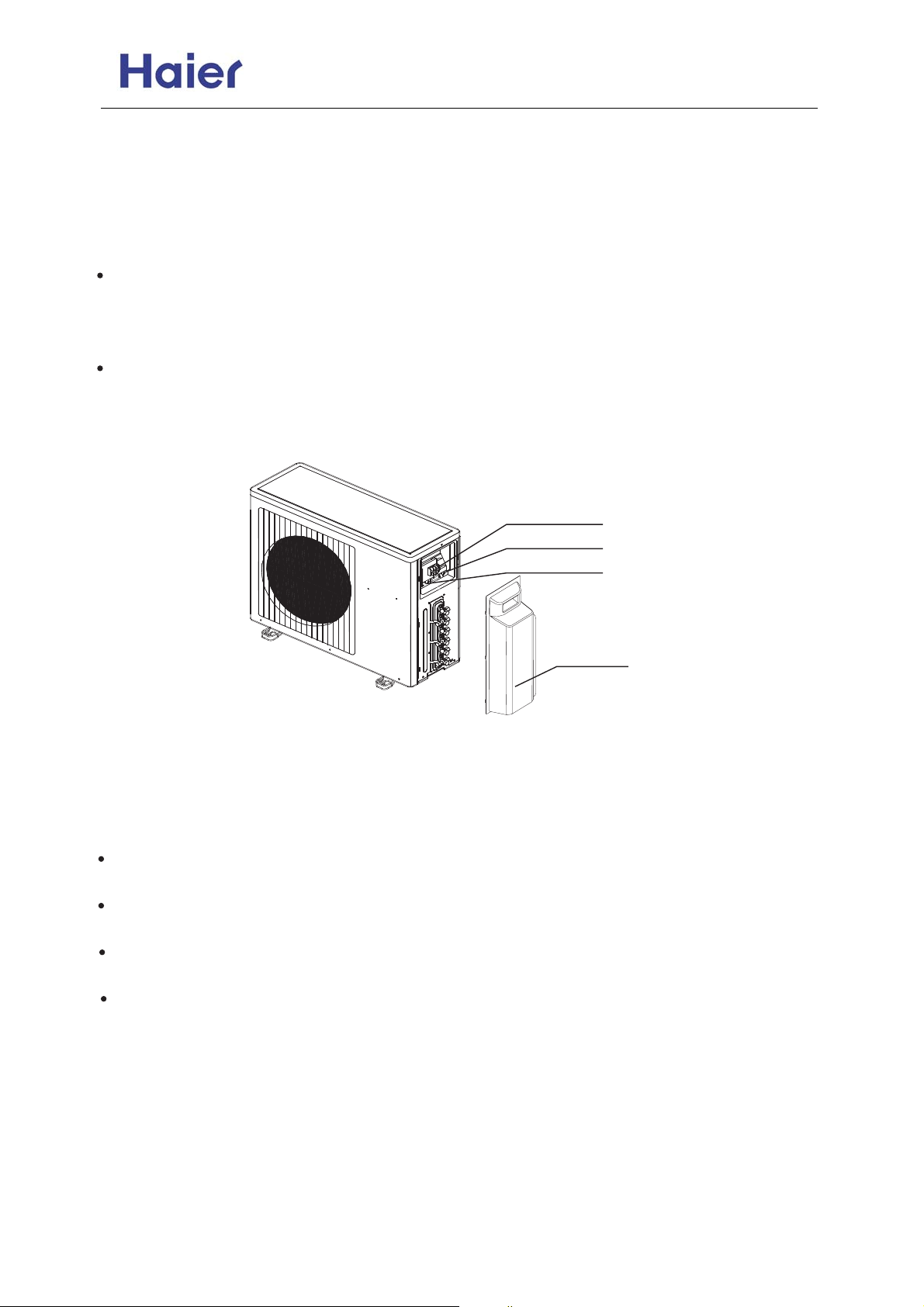
Crimp connection method for connection wire
After connection,the wire must be fastened by wire cover. The wire cover shall press on the protection
coat of the connection wire,as shown in right top figure.
Note:When connecting the wiring,confirm the terminal number of indoor and outdoor units carefully.
Incorrect wiring will damage the controller of air conditioner or the unit can not operate.
3. Wiring method of outdoor unit:
Power line
Remove the repair board of the outdoor unit and loosen the wire cover A,then put the live wire, neutral
wire and grounding wire through the wire cover ,and connect them to terminal block correspondingly. After connection, fasten wire cover to its previous state.
Communication wire of indoor unit.
Loosen wire cover , put the communication wire through the wire cover B, and connect them to
terminal block correspondingly. After connection, fasten wire cover B to its previous state.
Note: Power line and communication wire are provided by consumers themselves.
Terminal block
Wire cover A
Wire cover B
Valve cover
4. Wiring method of indoor unit
Loosen wire cover and connect the power line and communication wire of indoor unit to the
terminal correspondingly.
Note:
When connecting power line to power supply terminal, please pay attention to the following items:
Do not connect the power line with different dimensions to the same connection wire end.
Improper contact will cause heat generation.
Do not connect the power line with different dimensions to the same grounding wire end.
Improper contact will affect protection.
Keep a proper distance between the communication wire and the power line. Otherwise, abnormal
communication will occur because of disturbance.
Do not connect the power line to the connecting end of communication wire.
Incorrect connection will cause damage to the connected unit.
-24-
Page 25
AS072/092/122XVERA
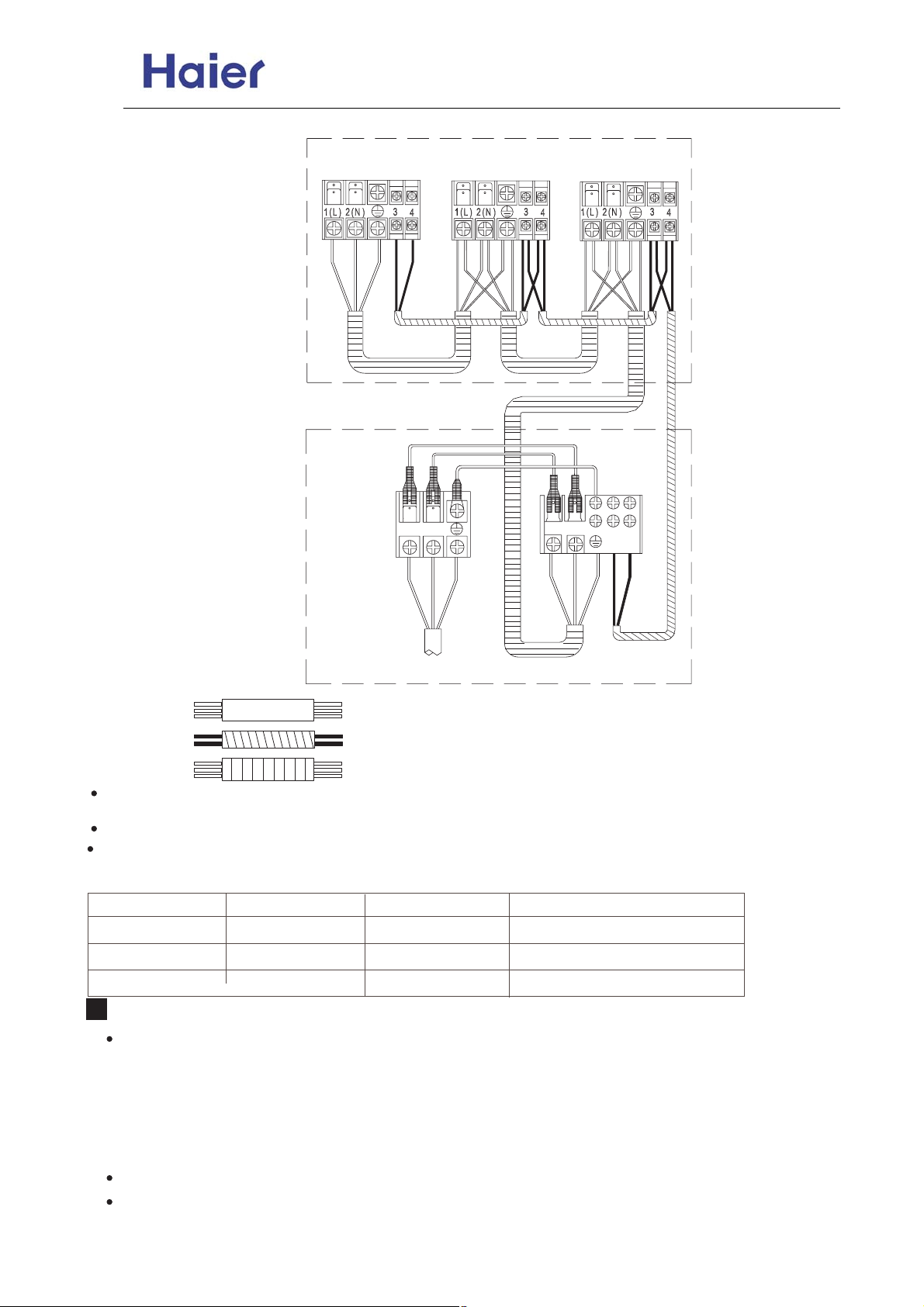
5. Example wiring diagram
Commercial Air Conditioner Model: AU18/222XFERA
Indoor unit C Indoor unit B Indoor unit A
LN NL
C1 C2
1PH, 220-230V~, 50Hz Outdoor unit
Power supply cable: H05RN-F 3G 4.0mm
Communication cable (Shield wire): H05RN-F 2X1.5mm
Connecting cable (Shield wire): H05RN-F 3G 2.5mm
2
2
2
Please refer to the indoor unit installation manual to find detailly how to set and check the communication
address.
Incorrect address setting will cause abnormal to the system.
The distance between the signal wires and the power cabes should be at least 50mm.
6. After installation, please fill in the following table for easy daily maintenance:
Indoor unit NO.
Room name
Model of indoor unit Serial No.
A
B
C
Test running
Before starting the test running, please confirm the following works have been done successfully.
1) Correct piping work;
2) Correct wiring work;
3) Correct match of indoor and outdoor unit;
4) Proper recharge of refrigerant if needed;
5)Correct indoor unit addresses setting.
Make sure that all the stop valves are fully open.
Check the voltage supplied to the outdoor and indoor units, please cinfirm that is 230V.
-25-
Page 26
Commercial Air Conditioner Model: AU18/222XFERA
AS072/092/122XVERA
Test running.
1) If the temperature is lower than 16 C, it is impossible to test cooling with remote controller, and also
when the temperature is higher than 30 C, it is impossible to test heating.
2) To test cooling, set the lowest temperature at 16 C. To test heating,set the highest temperature, at
30C.
3) Please check both cooling and heating operation of each unit individually and then also check the
simultaneous operation of all indoor units.
4)After ruuning the unit for about 20 minutes, check the indoor unit outlet temperature.
5) After the unit is stopped, or working mode changed, the system will not start again for about 3 minutes.
6)During cooling operation, frost may ocur on the indoor unit or pipes, this is normal.
7) Operate the unit according to the operation manual. Please kindly explain to our customers how to
operate through the instruction manual.
Items to confirm
Check items for test run, put mark " in ".
Gas leakage from pipe connection?
Heat insulation treatment of pipe connection?
Are the connection wiring of indoor and outdoor unit firmly inserted into the terminal block?
Is the connection wiring of indoor and outdoor firmly fixed?
Is drainage securely arranged?
Is the ground wire securely and firmly connected?
Is power supply voltage abided by electric code?
Is there any noise?
Does cooling perform normally?
Does room temperature regulator operate normally?
-26-
Page 27
Commercial Air Conditioner Model: AU18/222XFERA
AS072/092/122XVERA
Indoor unit installation
Cautions
All electrical repairs must be carried out
by qualified electricians. Inadequate repairs
may result in a major source of danger for
the user of the air conditioner.
Do not damage any parts of the air
conditioner that carry refrigerant by piercing
or perforating the air conditioner's tubes with
sharp or pointed items, crushing or twisting
any tubes, or scraping the coatings off the
surfaces. If the refrigerant spurts out and
gets into eyes, it may result in serious eye
injuries.
4. The wiring method should be in line with the
local wiring standard.
5. The power cable and connecting cable are selfprovided.
The requirement of the connecting cable:
Model
AS072XVERA
AS092XVERA
AS122XVERA
Connecting cable(sheilded wire)
H05RN-F 3G 2.5mm
H05RN-F 2X1.5mm
2
2
All the cables shall have got the Local
Do not obstruct or cover the ventilation
grille of the air conditioner. Do not put fingers
or any other things into the inlet/outlet and
swing louver.
Do not allow children to play with the air
conditioner. In no case should children be
allowed to sit on the outdoor unit.
authentication certificate.
6. The breaker of the air conditioner should be
all-pole switch; and the distance between its two
contacts should be no less than 3mm. Such
means for disconnection must be incorporation in
the fixed wiring.
Specifications
The refrigerating circuit is leak-proof.
The machine is adaptive in following
situation
1. Applicable ambient temperature range:
Cooling
Heating
Indoor
outdoor
Indoor
outdoor
Rated Maximum Minimum
27 32 18
DB C
19 23 14
WB C
35 43 10
DB C
24 26 6
WB C
20 27 15
DB C
14.5 -- --
WB C
7 24 -15
DB C
6 18 --
WB C
7. The waste battery shall be disposed properly.
8. The indoor unit installation height is at least
2m.
9. The appliance is not intended for ase young
children or infirm persons without super vision.
10. Young children should be super vised to
ensure that they do not play with the applience.
2. If the supply cord is damaged, it must
be replaced by the manufacturer or its
service agent or a similar qualified
person.
3. If the fuse on PC board is broken,
please change it with the type of T 3.15A
/250VAC
-27-
Page 28
Commercial Air Conditioner Model: AU18/222XFERA
AS072/092/122XVERA
1. Safety precautions
Carefully read the following information in order to operate the air conditioner correctly.
Below are listed three kinds of Safety Cautions and Suggestions.
WARNING!
CAUTION!
INSTRUCTIONS: These information can ensure the correct operation of the machine.
Be sure to conform with the following important Safety Cautions.
The Safety Cautions should be at hand so that they can be checked at any time when needed.
If the conditioner is transferred to the new user, this manual should be as well transferred to the new user.
Incorrect operations may result in severe consequences of death or serious injuries.
Incorrect operations may result in injuries or machine damages; in some cases may
cause serious consequences.
WARNING!
Don't blow the human body with the cooling
air too long, and don't let the room temperature decrease too low either.
Otherwise the one will feel unpleasant or
harm ones' health.
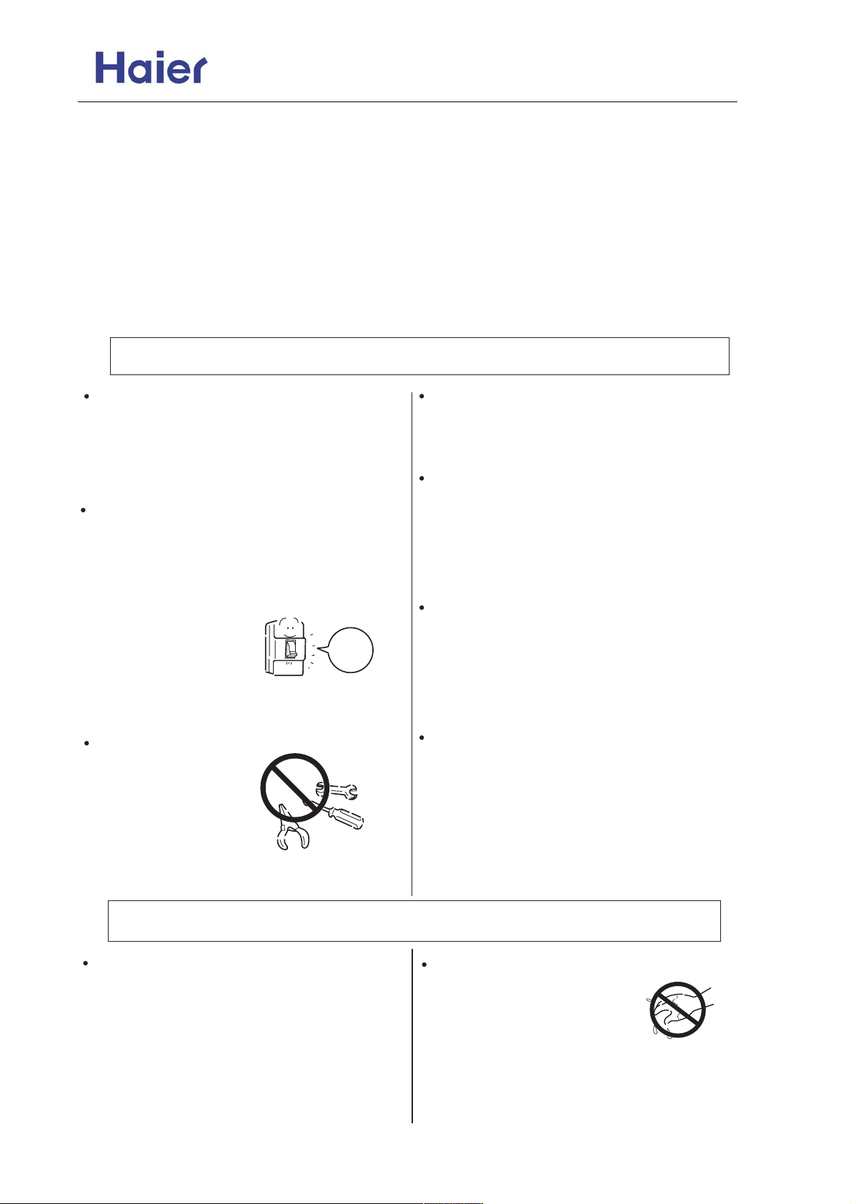
If any abnormal phenomena is found (e. g.
smell of firing), please cut off the power
supply immediately, and contact the dealer
to find out the handling method.
In such case, to continue
using the conditioner will
damage the conditioner,
and may cause electrical
shock or fire hazard.
When you need maintenance and repairment,
call dealer to handle it.
Incorrect maintenance and repairment
may cause water
leak, electrical shock
and fire hazard.
switch
off
Please let the dealer be responsible for installing
the conditioner.
Incorrect installation may cause water leak, electrical shock and fire hazard.
Don't put fingers or any other things into the
inlet/outlet and swing louver while the conditioner is in operation.
Because the highspeed fan is very dangerous
and may cause injuries.
Call the dealer to take measures to prevent the
refrigerant from leaking.
If conditioner is installed in a small room, be sure
to take every measure in order to prevent suffocation accident even in case of refrigerant leakage.
When conditioner is deinstalled or reinstalled
dealer should be responsible for them.
Incorrect installation may cause water leaking,
electrical shock and fire hazard.
CAUTIONS!
Conditioner should not be used for any other
purpose other than airconditioning.
Don't use air-conditioner for any other special
purposes, e.g. the preservation and protection
of food, animals, plants, pecision apparatus as
well as work of art, otherwise the qualities
of these stuffs may be damaged.
Don't operate the air-conditioner with damp
hands.
Otherwise will be shocked.
-28-
Page 29
Commercial Air Conditioner Model: AU18/222XFERA
AS072/092/122XVERA
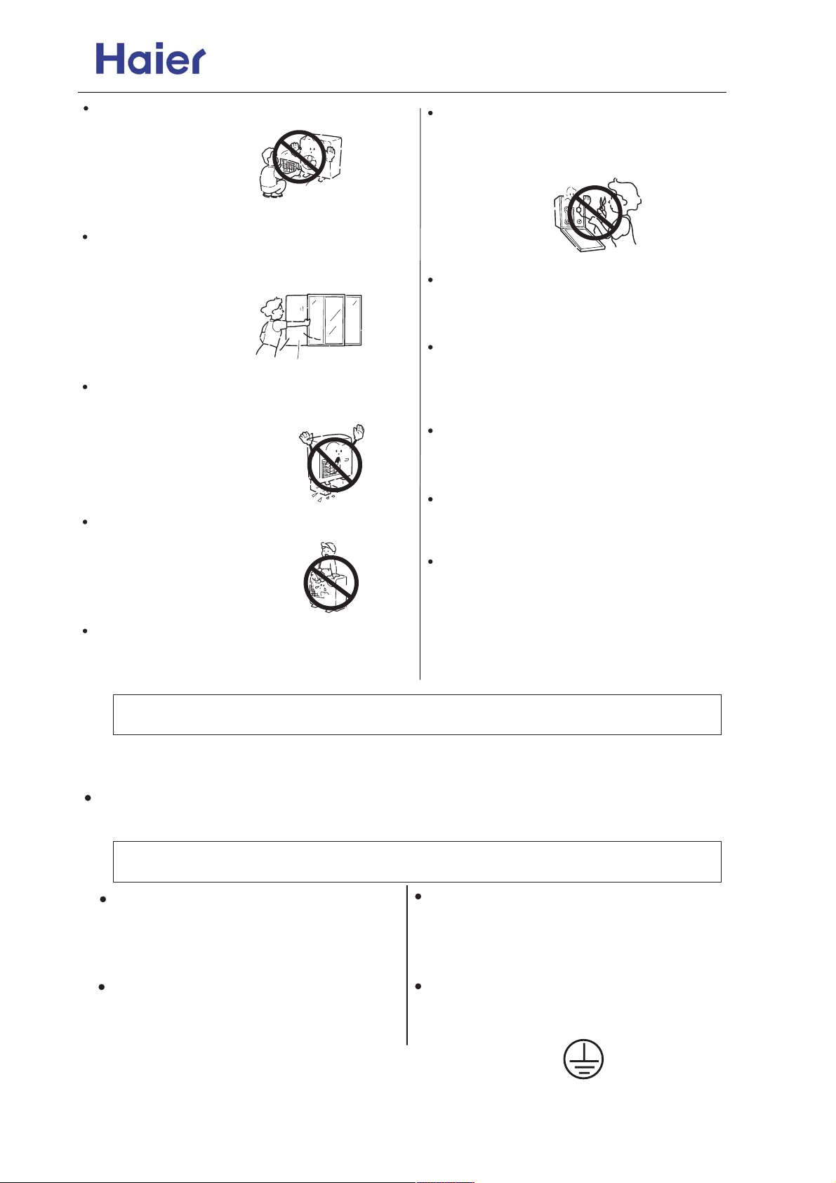
Don't dismantle the outlet of the outdoor unit.
The exposure of fan is
very dangerous which
may harm human beings.
When air-conditioner is co-used with other
heat-radiator the frequent replacement of
room atmosphere should be required.
Inefficient ventilation may cause
suffocation.
After a long time use of air-conditioner the
base should be checked for any damages.
If the damaged base is
not repaired, the unit
may fall down and
cause accidents.
No goods or nobody is permitted to placed on
or stand on outdoor unit.
The falling of goods and
people may cause accidents.
Pets and plants should not be blowed directly
in the air flow.
Otherwise will suffer damage.
Only use correctly-typed fuse.
May not use wire or any other materials
replacing fuse, otherwise may cause faults or
fire accidents.
Don't place any burning unit
air-conditioner,
combustion.
No inflammable spray fluid should be
permitted to be placed or used near to
airconditioner other wise may cause fire
accidents.
Air-conditioner should be cleaned only after
power supply is cut off to keep from shock or
hurt.
Don't clean air-conditioner with water.
Otherwise may cause shock.
When use the fumigating insecticide don't
open air-conditioner.
Otherwise the poisonous chemicals may settle
in air-conditioner which harm the health of
chemical-allergic people.
which may cause incomplete
in the air flow of
CAUTIONS ON INSTALLATION
Please ask the dealer or specialist to install, never try by the users themselves. After the installation please
be sure of the following conditions.
Please call dealer to install the air-conditioner.
Incorrect installation may cause water leaking, shock and fire hazard.
CAUTION !
Air-conditioner can't be installed in the
envi-ronment with inflammable gases
because the inflammable gases near to
air-conditioner may cause fire hazard.
Installed electrical-leaking circuit breaker.
It easily cause electrical shock without circuit
breaker.
Connect earthing wire.
Earthing wire should not be connected to the gas
pipe, water pipe, lightning rod or phone line, incorrect earthing may cause shock.
Use discharge pipe correctly to ensure efficient
discharge.
Incorrect pipe use may cause water leaking.
Earthing
-29-
Page 30
Commercial Air Conditioner Model: AU18/222XFERA
AS072/092/122XVERA
[Location]
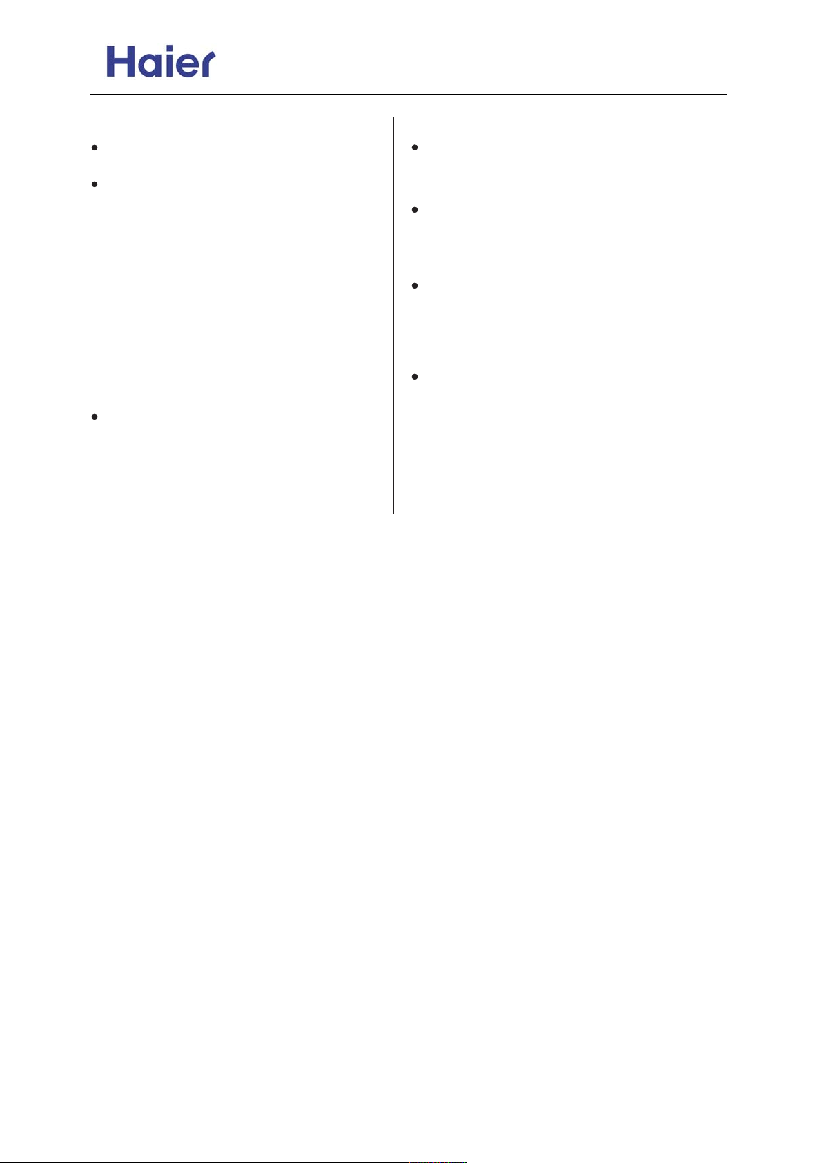
Air-conditioner should be located in wellvented and easily-accessible place.
Air-conditioner should not be located in the
following places:
(a) Places with machine oils or other oil
vapours.
(b) Seaside with high salt content in the air.
(c) Near to hot spring with high content of
sulfide gases.
(d) Area with frequent fluctuation of voltage
e.g. factory, etc.
(e) In vehicles or ships.
(f) Kitchen with heavy oil vapour or humidity.
(g) Near to the machine emitting electricmagnetic waves.
(h) Places with acid, alkali vapuor.
TV, radio, acoustic appliances etc are at
least 1 m far away to the indoor unit, outdoor
unit, power supply wire, connecting wire,
pipes, otherwise images may be disturbed
or noises be created.
As required, take measures against heavy
snow.
[Wiring]
Air-conditioner should be equipped with special
power supply wire.
[Operating noise]
Chose the following locations:
(a) Capable of supporting air-conditioner weight,
don't increase operating noise and vibration.
(b) Hot vapour from outdoor unit outlet and ope rating noise don't disturb neighbour.
No obstacles around the outdoor unit outlet.
-30-
Page 31
Commercial Air Conditioner Model: AU18/222XFERA
AS072/092/122XVERA
2. Emergency and Test Operation
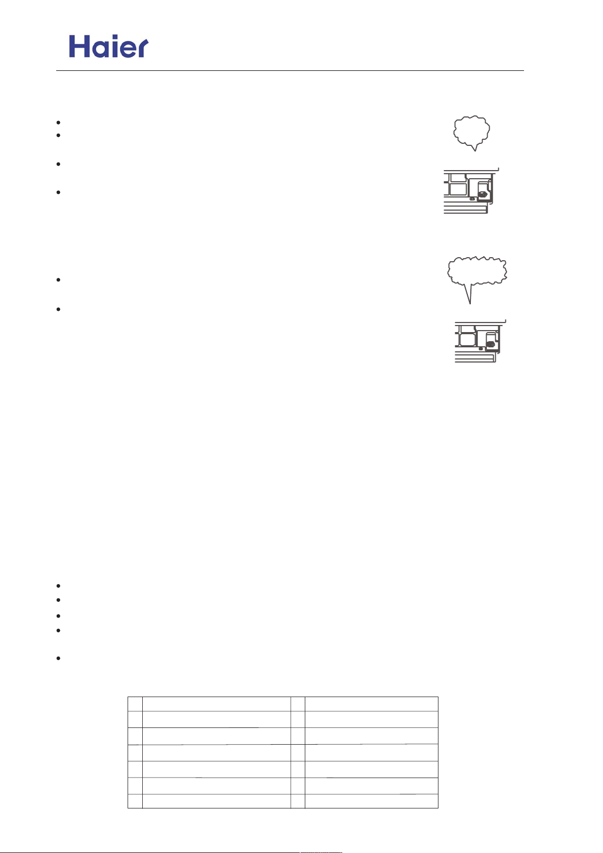
Emergency operation:
Use this operation only when the remote controller is defective or lost.
When the emergency operation switch is pressed "Pi" sound is heard once,
which means the start of this operation.
In this operation,the system automatically selects the operation modes, cooling
or heating, according to the room temperature.
When machine is running in emergency, the set value and wind speed of
temperature could not be altered; meanwhile, it can not operate for
dehumidifying or under timing mode.
pi
Test operation
Test operation switch is the same as emergency switch.
pi.....pi
Use this switch in the test operation when the room temperature is below
16 oC, do not use it in the normal operaion.
Continue to press the test operation swich for more than 5 seconds, after
you hear the "Pi" sound twice, release your finger from the switch:the
cooling operation starts with the air flow speed "Hi".
Removal of the restriction of emergency or test operation.
Press the emergency operation switch once more, or manipulate through the remote controller ; the
"Pi" sound, the emergency or test operation is stopped.
When the remote controller is manipulated, it gets the system back to the normal operation mode.
Disconnect power supply before clean the unit.
Don' t touch it with wet hand.
Don' t wash with hot water or solvent to clean the unit.
Air filter and outdoor cleaning
1.Open the inlet grill.
2.Detach the Air filters.
3.Use water or vacuum cleaner to clean it. If it is extremely dirty,wash it with neutral detergent or soap water.
4.Wash it with clean water and install it after complete dry.
5.Close the inlet grill.
Caution:
Do not use hot water over 40oC, as this may cause damage to air filter.
Wipe air filter carefully.
Clean it with warm and wet cloth or with neutral detergent, then wipe it dry with clean and soft cloth.
If air conditioner is very dirty, clean it with cloth soaked in neutral detergent, then wipe off the detergent
with clean water.
Don't use insecticide or other chemical detergents.
3. Preparation for installation
Installation tools
1 Screw Driver (flat head, wabbler, triangle)
2 Steel Saw
3 60mm Drill
4 Inner Hexagon Spanner
5 Shifting Spanner
6 Spanner
7 Pipe Cutter
8 Pipe Expander
9 Knives
10 Clippers
11 Leakage Checker or Soap Liquid
12 Measuring Tape
13 Scraper or File
14 Refrigeration Oil
-31-
Page 32
Commercial Air Conditioner Model: AU18/222XFERA
AS072/092/122XVERA
4. Accessories for installation
Self-contained accessories
No. A B
Name of
Parts
Non-adhesive
Tape
Adhesive
tape
CDEF
Connecting
Hose
Heat
insulation
material
Gypsum
powder
Drain hose
5. Choose the installation place
Install the indoor unit where the weight of the unit can be supported.
Install the indoor unit where the heat source and steam source are not close and the unit inlet and
outlet are not blocked.
Install the indoor unit where the drainage is easy and the outdoor unit can be easily connected.
Install the indoor unit where its cold air and hot air can be easily sent to all the comers of the room.
Install the indoor unit where the power socket is near and there is sufficient space around the indoor unit.
Install the indoor unit where there is no T.V set, radio set, and wireless applian ce underneath, and
the sunlight lamp is over one meter away.
If the remote controller is installed on the wall, the indoor unit shall be ensured to receive the signal
while the sunlight lamp is on.
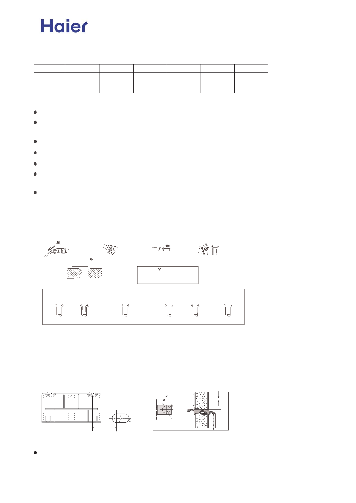
6. Method for Cutting and Expanding Pipes.
When the pipe is too long or the mouth is damaged, the pipe needs to cut or expanded.
1.cutting hose 2.Removing burr 3.Put on nut 4.Expand Hose
A
Hose Expander
Correct Not Correct
cracks on expanded mouth
Expansion Size
Hose dia.
6.35 mm(1/4)
9.52 mm(3/8)
Size (mm)A
0.8-1.5
1.0-1.5
burr incomplete too longTilting
7. When the mounting plate is first fixed
1. Carry out, based on the neighboring pillars or lintels, a proper leveling for the plate to be fixed against
the wall, then temporarily fasten the plate with one steel nail.
2. Make sure once more the proper level of the plate, by hanging a thread with a weight from the central
top of the plate, then fasten securely the plate with the attachment steel nail.
A=80mm
60mm
35
2-5mm
3. Making a Hole on the wall and Fitting the piping Hole cover.
Make a hole of 60mm in diameter, slightly descending to outside the wall.
Install piping hole cover and seal it off with putty after installation.
-32-
Page 33
Commercial Air Conditioner Model: AU18/222XFERA
AS072/092/122XVERA
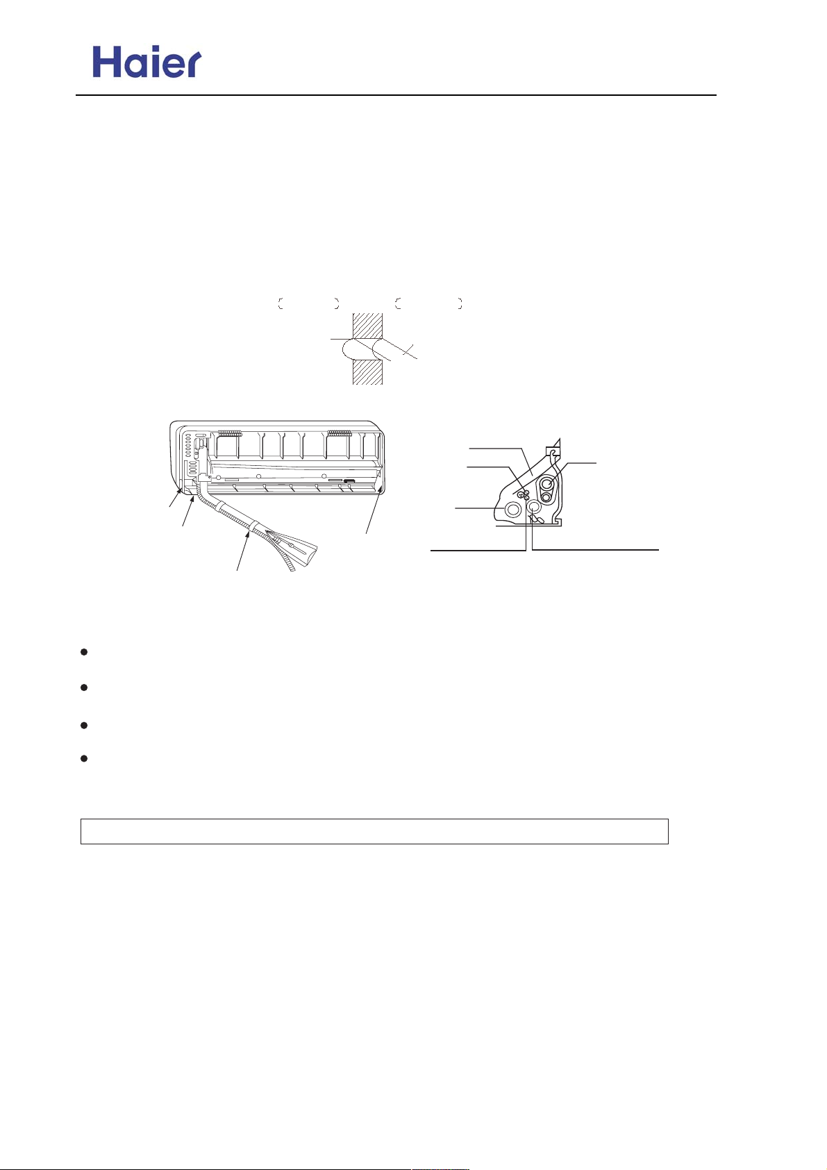
4. Drawing of pipe Rear piping
Draw pipes and the drain hose, then fasten them with the adhesive tape. Left Left-rear, piping.
In case of left side piping, cut away, with a nipper, the lid for left piping.
In case of left-rear piping, bend the pipes according to the piping direction to the mark of hole for
left-rear piping which is marked on heat insulation materials.
(1) Insert the drain hose into the dent of heat insulation materials of indoor unit.
(2) Insert the indoor/outdoor electric cord from backside of indoorunit, and pull it out on the front side,
then connect them.
(3) Coat the flaring seal face with refrigerant oil and connect pipes.
Cover the connection part with heat insulation materials closely, and make sure fixing with adhesive tape.
Indoor side
Wall hole
70mm
(Section of wall hole) Piping hole pipe
Lid for right piping
Lid for under piping
Lid for left piping
Fix with adhesive tape
Outdoor side
Thickness
of wall
Heat insulation
material
signal wire
Drain hose
Indoor/outdoor
electric cable
Indoor/outdoor electric cord and drain hose must
be bound with refrigerant piping by protecting
tape
Piping
Change-for-fresh-air tube
8. Other direction piping
Cut away, with a nipper, the lid for piping according to the piping direction and then bend the
pipe according to the position of wall hole. When bending, be careful not to crash pipes.
Connect beforehand the indoor/outdoor electric cable, and then pull out the connected to the heat
insulation of connecting part specially.
Hang surely the unit body onto the upper notches of the mounting plate. Move the body from side to
verify its secure fixing.
In order to fix the body onto the mounting plate, hold up the body aslant from the underside and then
put it down perpendicularly.
9. Indoor unit communication addresses setting
CAUTION! FAIL TO DO THIS, THE UNIT WILL NOT WORK.
1.There are two methods to set the communication address
A. Use the remote controller(default status in first installation).
B. Use dip switches on the indoor unit PCB.
2. Address setting procedure when using the remote controller.
A. Set the addresses only after the successful installation of the refrigerant pipes and connecting cables,
and open all the stop valves;
B. Please confirm that the indoor units and the outdoor unit in the same system use the same power
source;
C. Power on the units, but put all the indoor units in the status of STANDBY;
D. Please note that the address must be set as following:
Indoor unit that connect to valve A, the address must be 1;
Indoor unit that connect to valve B, the address must be 2;
Indoor unit that connect to valve C, the address must be 3;
E. Example: set unit A to address 1.
-33-
Page 34
Commercial Air Conditioner Model: AU18/222XFERA
AS072/092/122XVERA
Continuously press the emergency switch for about 15 seconds, the buzzer will sound 4 times(PI PI PI
PI) and then leave go of the switch. At this time, the indoor unit has entered the address setting procedure.
But the LCD display board is blank.
F. Use the controller to turn on the indoor unit. At this time, the controller should be changed from OFF
to ON, and then the LCD display board will display number 1. That is to say, the address setting is
enabled.
G. Press the button SLEEP on the controller, the times you press it stands for the address you want to
set, detailed as following:
Press button SLEEP one time, the address is 1, and the LCD display board shows 1;
Press button SLEEP two times, the address is 2, and the LCD display board shows 2;
Press button SLEEP three times, the address is 3, and the LCD display board shows 3;
H. Use the remote controller to turn off the unit, At this time, the controller should be changed from ON
I. If you want to change the address, please repeat the above steps from E to G.
J. After setting all the addresses, please power off the system and then power on again. Otherwise the
system will not start to work.
K. Once the addresses are successfully set, please do not change it any more to avoid confusion.
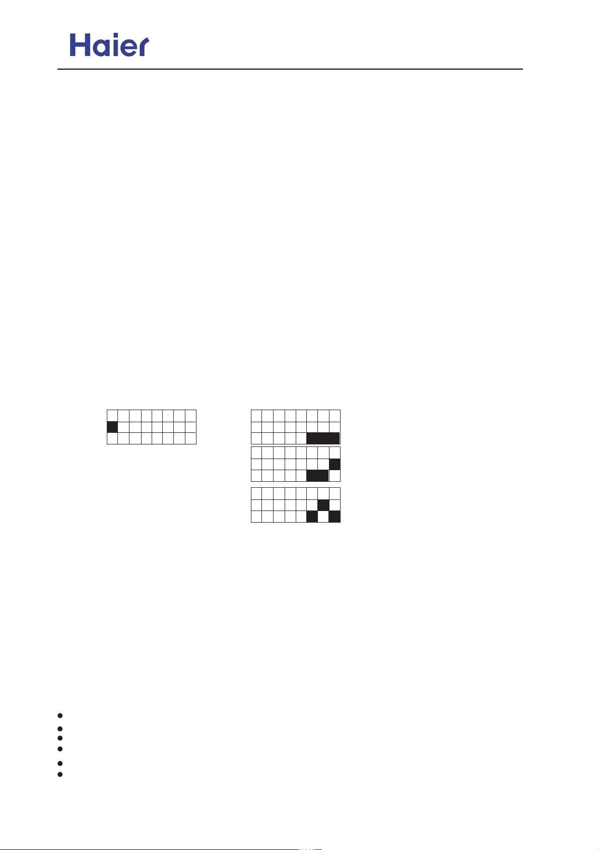
3. Address setting procedure when using the DIP switches SW01 and SW02.
A. The DIP switches SW01 and SW02 are on the indoor unit PCB.
B. Before carrying out the address setting work, the system must be powered off.
C. Take off the front panal and the filters, then take off the flaps and also the front cover,disconnect the
swing motor connectors from the PCB and then take out the lower part of the PCB.
D. Change the position of DIP 1 of SW01 from OFF to ON, if fail to do this, the addresses set by SW02
will not work.
E. Use SW02 to set the addresses as following(DO NOT CHANGE OTHER DIP SWITCHES):
SW01
1 2 3 4 5 6 7 8
SW02
1 2 3 4 5 6 7 8
ON
OFF
INDOOR UNIT ADDRESS
ON
OFF
1
1 2 3 4 5 6 7 8
ON
OFF
2
1 2 3 4 5 6 7 8
ON
OFF
3
4. How to check the addresses?(necessary procedure)
When finish all the above works, please power off and power on again to the whole system but set all
the indoor units in STANDBY. Then continously press the emergency switch until you hear the buzzer
sound 5 times(Pi Pi Pi Pi Pi), and then the LCD display board will show the address of this indoor unit.
Press any key on the remote controller, it will exit the address checking precedure.
10.Installation check and trial operation
Check the Layout of the Drain Pipe and Connection Wires, and also the piping and address setting.
The drain pipe should be placed underneath, and the connection wires should be placed upside;
and the drain pipe especially the section inside the machine and indoors must be wound up with
insulating material to preserve heat. The drain pipe shall be sloped and no concave and convex
shall occur along the whole pipe. And the cases as the right figure indicates shall not occur.
10.1 Installation check
Is power supply voltage required?
Is water completely drained to outdoors?
Are power wire and connection wires between indoor and outdoor units correctly connected?
Is any gas leaked from the pipe connectors?
Are series numbers of the terminals on the indoor and outdoor units corresponding to each other?
Is the connection section of the auxiliary pipe insulated? Is the indoor unit fixed firmly?
Is noise big?
-34-
Page 35
Commercial Air Conditioner Model: AU18/222XFERA
AS072/092/122XVERA
10.2 Trial operation
The person who has completed this installation shall be requested to conduct a test operation for check:
Is the temperature adjuster working normally?
Does the location for installation conform to requirements?
Winding up with Protective Plastic Tape.The connection pipes,drain pipe, and the connection wires shall
be wound up with PVC tape.
Notes: The connection pipes shall also be wound up with insulating material to preserve the temperature.
The airing direction shall be from bottom to top.
-35-
Page 36

AS072/092/122XVERA
Commercial Air Conditioner Model: AU18/222XFERA
6. Parts and Functions
.;< 3;?4=
.4=96:18 28;37
06=4 3;?4= +
06=4 3;?4= ,
/18?4 3;?4=
+6= 6:84> 5=6884
->;< ?18?4
Air inlet grille
Front panel
Air inlet grille
Display board
Louver
-36-
Page 37
Commercial Air Conditioner Model: AU18/222XFERA
AS072/092/122XVERA
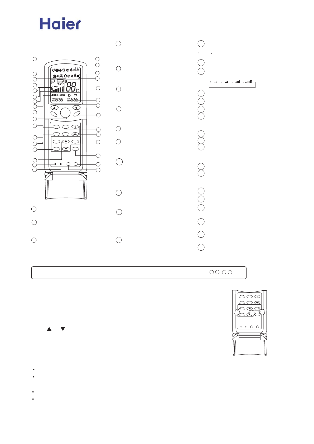
7. Remote controller YR-H65
20
19
18
17
24
23
16
15
11
HEALTH FAN
1
2
8
3
4
7
6
31
MODE
SLEEP
CLOCK
TIMER
RESET
2
o
TEMP
ON
OFF
HEALTH AIRFLOW
FRESH
CODE
SWING
SET
STERILIZE
LOCKLIGHT
B
A
21
22
27
28
25
26
14
12
30
13
9
29
5
10
TIMER
Used to select TIMER ON,
TIMER
OFF, TIMER ON/OFF.
LOCK
5
Used to lock buttons and LCD
display.
RESET
6
Used to reset the controller back
to normal condition.
HOUR
7
Used to set clock and timer
setting.
8
SLEEP
Used to select sleep mode
9
SET
Used to confirm Timer and Clock
setting.
LIGHT
10
Control the light up and go out of
the control panel's background
light source and control the
14
Used to set temp.,temp. range:16
C~30 C
15
16
17
18
19
20
21
22
23
24
25
4
switch of the buzzer.
Power ON/OFF
1
Used for unit start and stop.
MODE
2
Used to select AUTO run,COOL,
DRY, HEAT and FAN operation.
CLOCK
3
Used to set correct time.
Note: This model does not have the following related display and function
11
HEALTH
Used to set Health operation
function
12
FAN
Used to select fan speed: AUTO,
LOW FAN, MED FAN, HIGH
FAN.
13
SWING
Used to set UP/DOWN air
sending and RIGHT/LEFT air
sending direction.
26
27
28
29
30
31
For this unit, please set to code A
TEMP
Timer ON/OFF display
Fan speed and air sending
direction display
LOW MID HIGH AUTO
Swing direction display
Room temperature display
Sleep state display
Health display
Display when set Health
operation function.
Electric Heating display
Fresh Air state display
Battery Capacity display
Display when the electric power
of the battery is insufficient.
Lock state display
Temperature display
Used to display the set
temperature
Clock display
Humidifying display
Sterilize display
(This function is optional)
STERILIZE
(This function is optional)
HEALTHAIRFLOW
Used to set healthairflow
CODE A/B selection
23
21
18
27
Clock set
When unit is started for the first time
and after replacing batteries in remote
controller, clock should be adjusted as follows:
Press CLOCK button, "AM"or "PM" flashes.
MODE
HEALTH AIRFLOW
SLEEP
FRESH
SWING
CLOCK
TIMER
1
RESET
SET
STERILIZE
3
2
LOCKLIGHT
CODE
Press or to set correct time. Each press will increase
or decrease 1 min . If the button is kept pressed, time will change quickly.
After time setting is confirmed, press SET, "AM" and "PM"
stop flashing, while clock starts working.
Remote controller's operation
When in use, put the signal transmission head directly to the receiver hole on the indoor unit
The distance between the signal transmission head and the receiver hole should be within 7m without
any obsacles as well.
Don't throw the controller, prevent it from being damaged.
When electronic-started type fluorescent lamp or change-over type fluorescent lamp or wireless
telephone is installed in the room, the receiver is apt to be disturbed in receiving the signal so the
distance to the indoor unit should be shorter.
-37-
Page 38
Commercial Air Conditioner Model: AU18/222XFERA
AS072/092/122XVERA
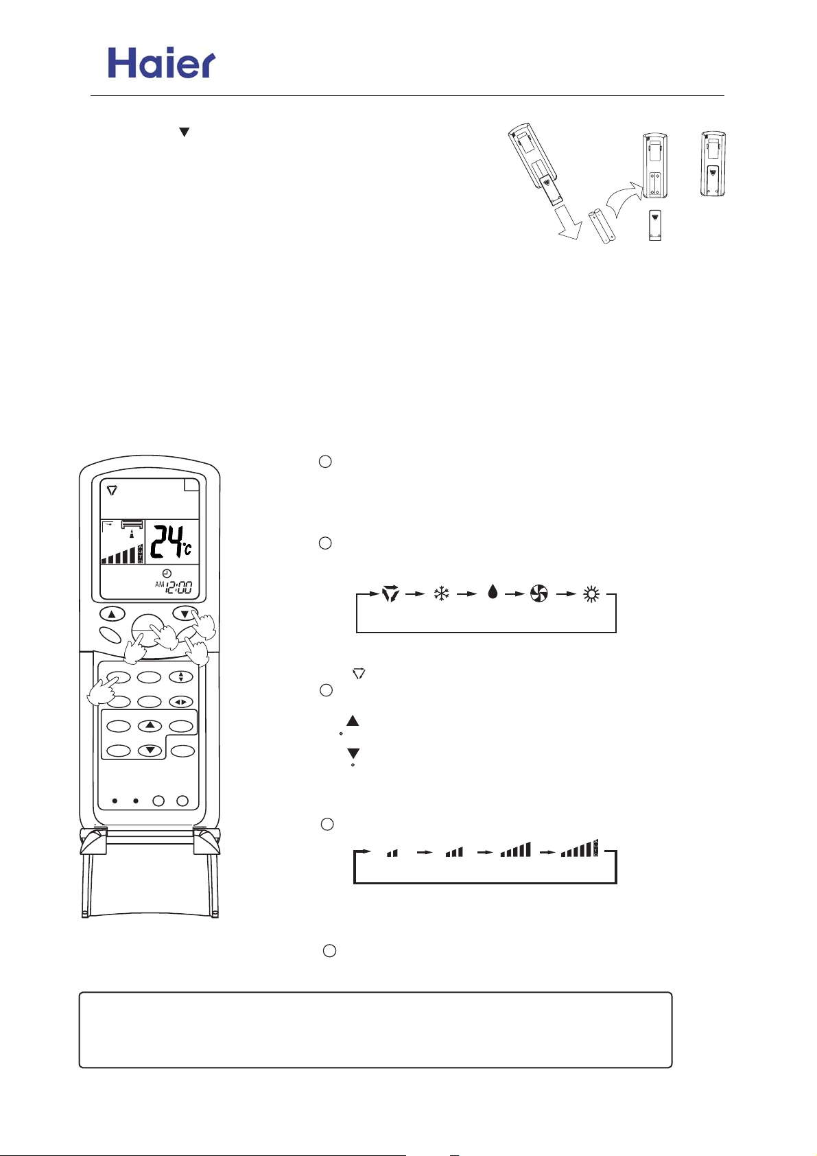
Loading of the battery
Slightly press " " and push down the cover.
Load the batteries as illustrated.
2 R-03 dry batteries, (cylinder)
Be sure that the loading is in line with the "+"/"-" pole
request as illustrated.
Put on the cover again.
MINUTES
Confirmation indicator:
In disorderation, reload the batteries or load the new batteries
2R-03 dry batteries
after 5 mins.
Note:The waster batteries should be disposed properly,use two
new same-type batteries when loading.
If the remote controller cant function normally or doesnt work at
all,use a sharp-pointed item to press the reset key.
Hint:Remove the batteries in case unit wont be in usage for a long period.
If there are any displays after taking-out just need to press reset key.
When throw away the waste batteries, please perform in accordance with the local regulation.
Auto operation
1
Press ON/OFF button
HEALTH
A
TEMP
ON
OFF
5
HEALTH AIRFLOW
MODE
RRESH
SLEEP
2
CLOCK
TIMER
CODE
RESET
1
STERILIZE
SWING
SET
LOCKLIGHT
3
FAN
4
Remote
controller
Unit starts running.
The previous status appears on the display(except. TIMER,
SLEEP mode)
2
Press MODE button. For each press, operation mode changes
as follows:
AUTO COOL DRY FAN HEAT
Select Auto run,
" " appears and auto run starts.
3
Select temp. button
Press TEMP button
Every time the button is pressed, temp. setting increases 1
C
Every time the button is pressed, temp. setting decreases
1 C
If the button is kept pressed, setting will increase or decrease
quickly.
4
Press FAN,For each press, operation mode changes as follows:
Remote
controller
LOW MID HIGH AUTO
Unit runs at the speed displayed on LCD.
When fan speed is AUTO,it is changed automatically
according to the indoor temperature.
5
Press ON/OFF button
Unit stops running.
Note:
During Auto run operation, temp. setting will be shown in LCD display, unit will select heating,
cooling or fan operation according to the room temp.
-38-
Page 39
Commercial Air Conditioner Model: AU18/222XFERA
AS072/092/122XVERA
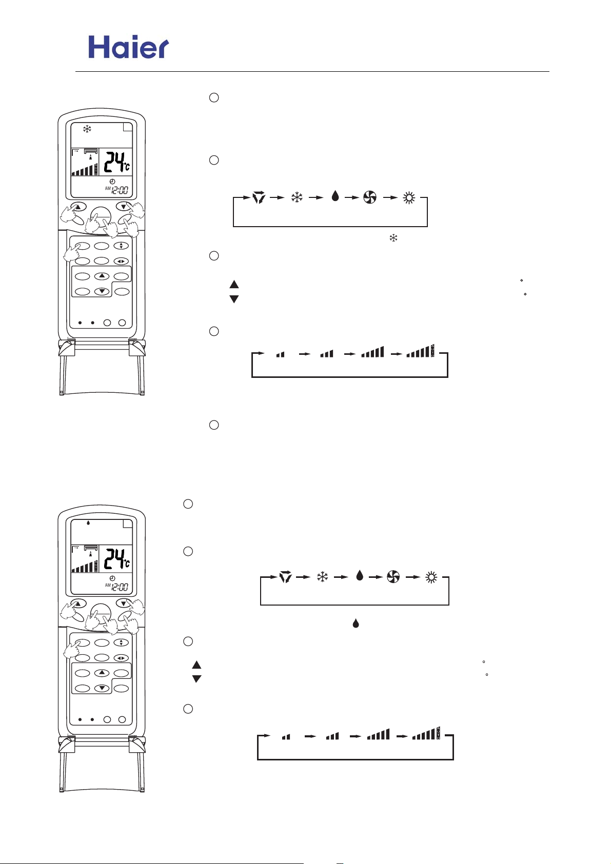
Cooling operation
1
Press ON/OFF button
A
Unit starts running.
The previous status appears on the display(except. TIMER, SLEEP
mode)
2
Press MODE button. For each press, operation mode changes
as follows:
TEMP
3
HEALTH
ON
OFF
1
5
HEALTH AIRFLOW
MODE
FRESH
SLEEP
2
CLOCK
TIMER
RESET
CODE
SWING
SET
STERILIZE
LOCKLIGHT
Dry operation
3
FAN
4
Remote
controller
AUTO COOL DRY FAN HEAT
Select cooling operation, Shows" "
3
Select temp. button
cooling operation starts.
Press TEMP button
Every time the button is pressed, temp. setting increases 1 C
Every time the button is pressed, temp. setting decreases 1 C
If the button is kept pressed, setting will increase or decrease quickly.
4
Press FAN button. For each press, fan speed changes as follows:
Remote
controller
LOW MID HIGH AUTO
Unit runs at the speed displayed on LCD. When fan speed is AUTO,it
is changed automatically according to the indoor temperature.
5
Press ON/OFF button
Unit stops running,and when entry this mode for the next time,it will show
the previous setting.
3
HEALTH
1
Press ON/OFF button
A
Unit starts running.
The previous status appears on the display (except. TIMER, SLEEP mode)
2
Press MODE button. For each press, operation mode changes as follows:
Remote
TEMP
ON
OFF
1
MODE
HEALTH AIRFLOW
SLEEP
FRESH
2
CLOCK
TIMER
5
3
FAN
4
SWING
SET
STERILIZE
controller
Select Drying operation shows" " Dry operation starts
3
Select temp. button
Press TEMP button
Every time the button is pressed, temp. setting increases 1 C
Every time the button is pressed, temp. setting decreases 1 C
AUTO COOL DRY FAN HEAT
If the button is kept pressed, setting will increase or decrease quickly.
4
RESET
CODE
LOCKLIGHT
Press FAN button. For each press, fan speed changes as follows:
Remote
controller
LOW MID HIGH AUTO
-39-
Page 40
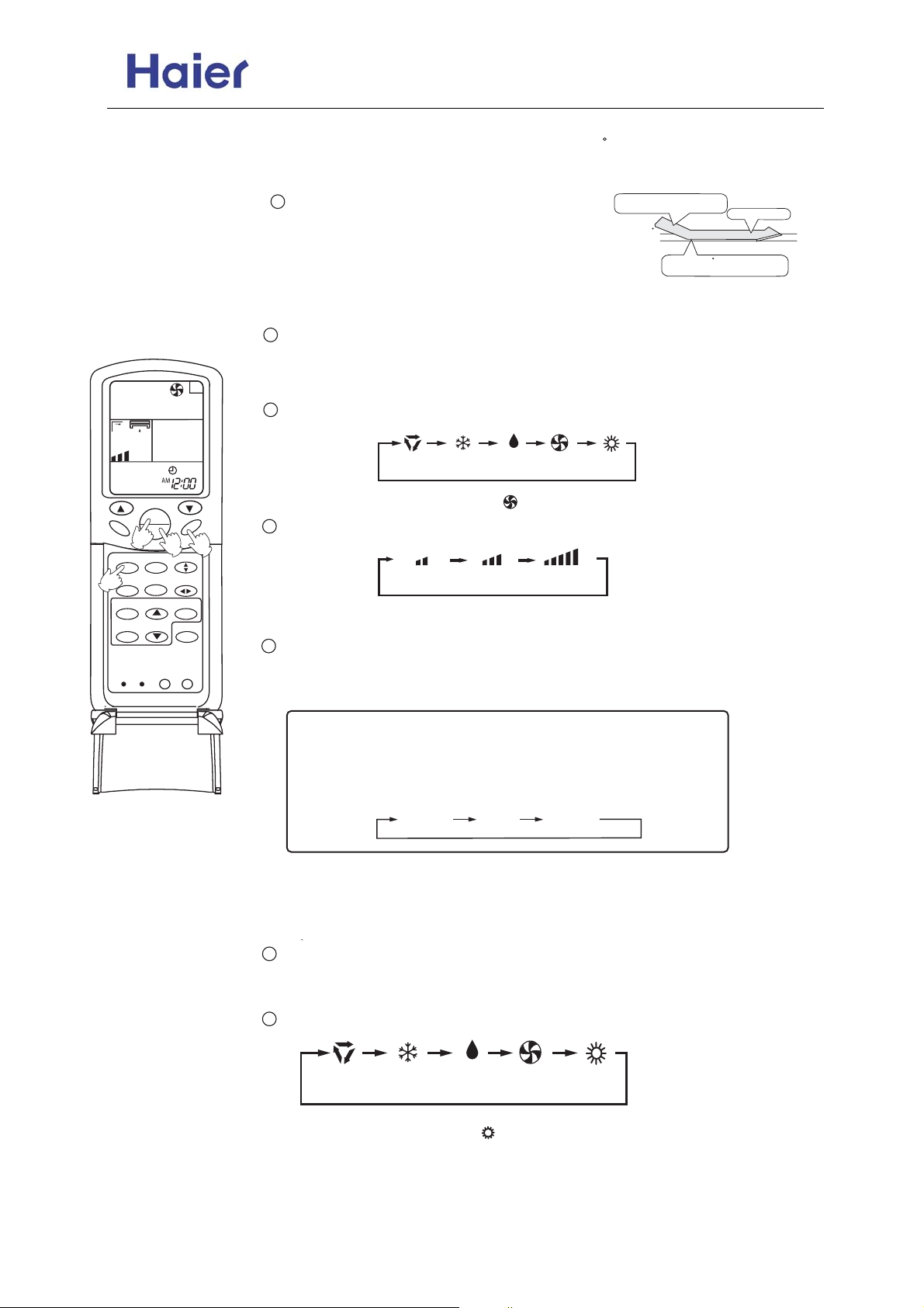
Commercial Air Conditioner Model: AU18/222XFERA
AS072/092/122XVERA
Unit runs at the speed displayed on LCD.
In DRY mode, when room temp.becomes 2 C lower than temp. setting,unit
will run intermittently at LOW speed regardless of FAN setting.
Fan operation
A
TEMP
ON
HEALTH
OFF
1
4
HEALTH AIRFLOW
MODE
FRESH
SLEEP
2
CLOCK
TIMER
CODE
RESET
3
SWING
SET
STERILIZE
LOCKLIGHT
5
Press ON/OFF button
Unit stops running, and when
entering this mode for the next
time, it will show the previous setting
1
Press ON/OFF button
COOL operation starts when room
temp. is higher than temp. setting.
Temp.setting+2 C
Temp.setting
On reaching 2 C lower than temp.
setting,unitwill run in mild DRY mode.
Ultra-low air flow
Unit starts running.
The previous status appears on the display (except. TIMER, SLEEP mode)
2
Press MODE button. For each press,operation mode changes as follows:
Remote
controller
AUTO COOL DRY FAN HEAT
Select Fan operation shows " ", Fan operation starts.
3
FAN
Press FAN button. For each press, fan speed changes as follows:
LOW MID HIGH
Unit runs at the speed displayed on LCD.
4
Press ON/OFF button
Unit stops running, and when entering this mode for the next time, it will
show the previous setting.
Note:
In this mode, temp. can't be selected, temp.setting will not
be shown in LCD display.In Fan operation mode, "AUTO"
fan speed is not available. Operation cycles are as follows:
LOW MID HIGH
Heating operation
Note: For cooling only type, this function is invalid.
1
Press ON/OFF button
Unit starts running.
The previous status appears on the display (except. TIMER, SLEEP mode)
2
Press MODE button. For each press,operation mode changes as follows:
AUTO COOL DRY FAN HEAT
Select Heating operation " " appears and Heating operation starts.
-40-
Page 41
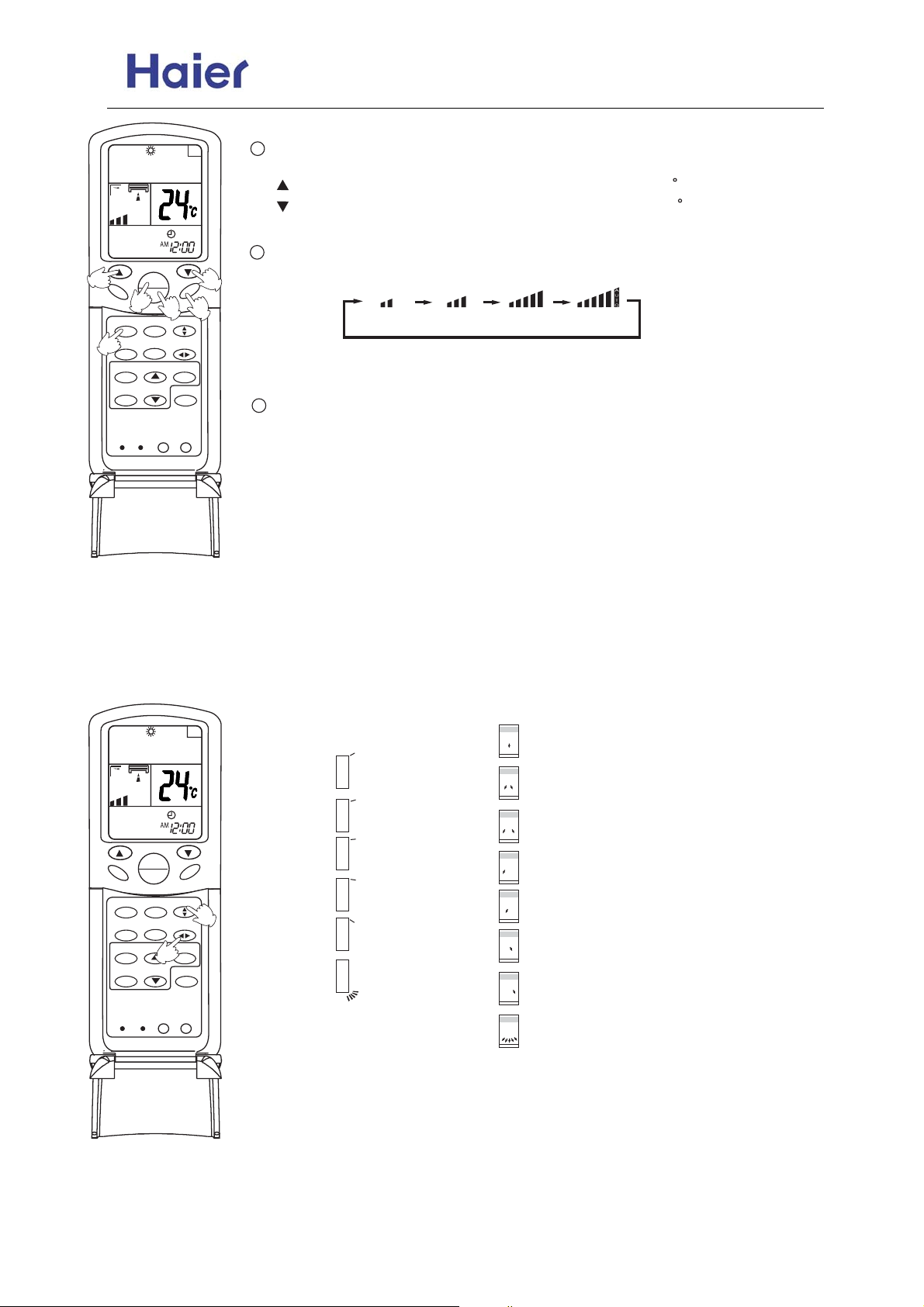
Commercial Air Conditioner Model: AU18/222XFERA
AS072/092/122XVERA
3
HEALTH
A
3
Select temp. button
Press TEMP button
Every time the button is pressed, temp. setting increases 1 C
Every time the button is pressed, temp. setting decreases 1 C
If the button is kept pressed, setting will increase or decrease quickly.
4
TEMP
ON
OFF
1
HEALTH AIRFLOW
MODE
FRESH
SLEEP
2
CLOCK
TIMER
CODE
RESET
5
SWING
SET
STERILIZE
LOCKLIGHT
3
FAN
4
Press FAN button. For each press, fan speed changes as follows:
LOW MID HIGH AUTO
In heat mode,warm air will blow out after a short period of time due to colddraft prevention function.
5
Press ON/OFF button
Unit stops running, and when entering this mode for the next time, it will show
the previous setting.
Air flow adjustment
Swing louvers
(Vertical louvers)
(Horizontal louvers)
A
TEMP
HEALTH
RESET
MODE
SLEEP
CLOCK
TIMER
ON
OFF
HEALTH AIRFLOW
FRESH
CODE
FAN
1
SWING
SET
2
STERILIZE
LOCKLIGHT
Up and down
Position 1
Position 2
Position 3
Position 4
Position 5
Position 6
[COOL/DRY/FA
N/AUTO(COOL)
HAVE NOT]
(AUTO SWING)
Side from side
Position 1
Position 2
Position 3
Position 4
Position 5
Position 6
Position 7
Position 8
-41-
Page 42
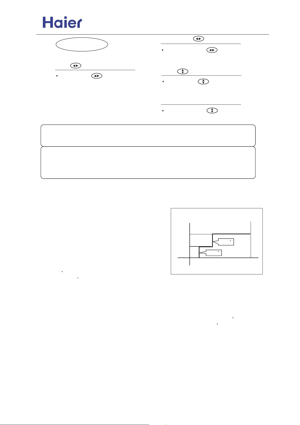
Commercial Air Conditioner Model: AU18/222XFERA
AS072/092/122XVERA
Fixed position
Side from side
Press the SWING again to fix the
vertical louvers at your desired position.
Swing
Swing
Press SWING the vertical
louvers move from side to side.
Press SWING the horizontal
louvers move from up to down.
Fixed position
Press the SWING again to fix the
horizontal louvers at your desired position.
Note:
Put louvers at up position in cooling and down position in heating mode.
This will be helpful to keep an even room temp.
Notice:
In cooling or dry operation, don't put horizontal louvers at downward
position for a long time, or outlet grill might get frosted. Don't expose
your skin to cool or warm air for a long time.
Sleep operation
Remote control unit
Before go to bed, you can press the Sleep button, the air
conditioner will operate in comfortable sleep mode to make
your sleep more comfortable.
Usage of the Sleep function
After starting, set the Run mode and press the Sleep button.
Run mode
1. In cooling and dry
After starting of the Sleep operation, the temperature will
be raised for 1 C higher than the set temperature 1 hour
later,and be raised for 1 C after another hour. It continues
under that condition for 6 hours, then the machine will be
switched off. The temperature is higher than the set
temperature so as to avoid catching cold in sleeping.
The Sleep running starts The Sleep running stops
About 6 hours
Raise 1 C
Raise 1 C
In cooling and dry
Close down
the machine
Set the
temperature
1 hour
1 hour
2. In heating ( the single-cooling conditioners do not have the function)
After the Sleep running starts, the temperature will drop for 2 C after another one hour. The temperature
will raise for 1 C after 3 hours running under the above temperature, and the conditioner will be closed
down after running for 3 hours. The temperature is lower than the set temperature so as to avoid
uneasiness in sleeping.
3. In automatic running
The conditioner will run under automatically selected working mode of sleeping.
4. In Fan running
The Sleep function is invalid.
-42-
Page 43
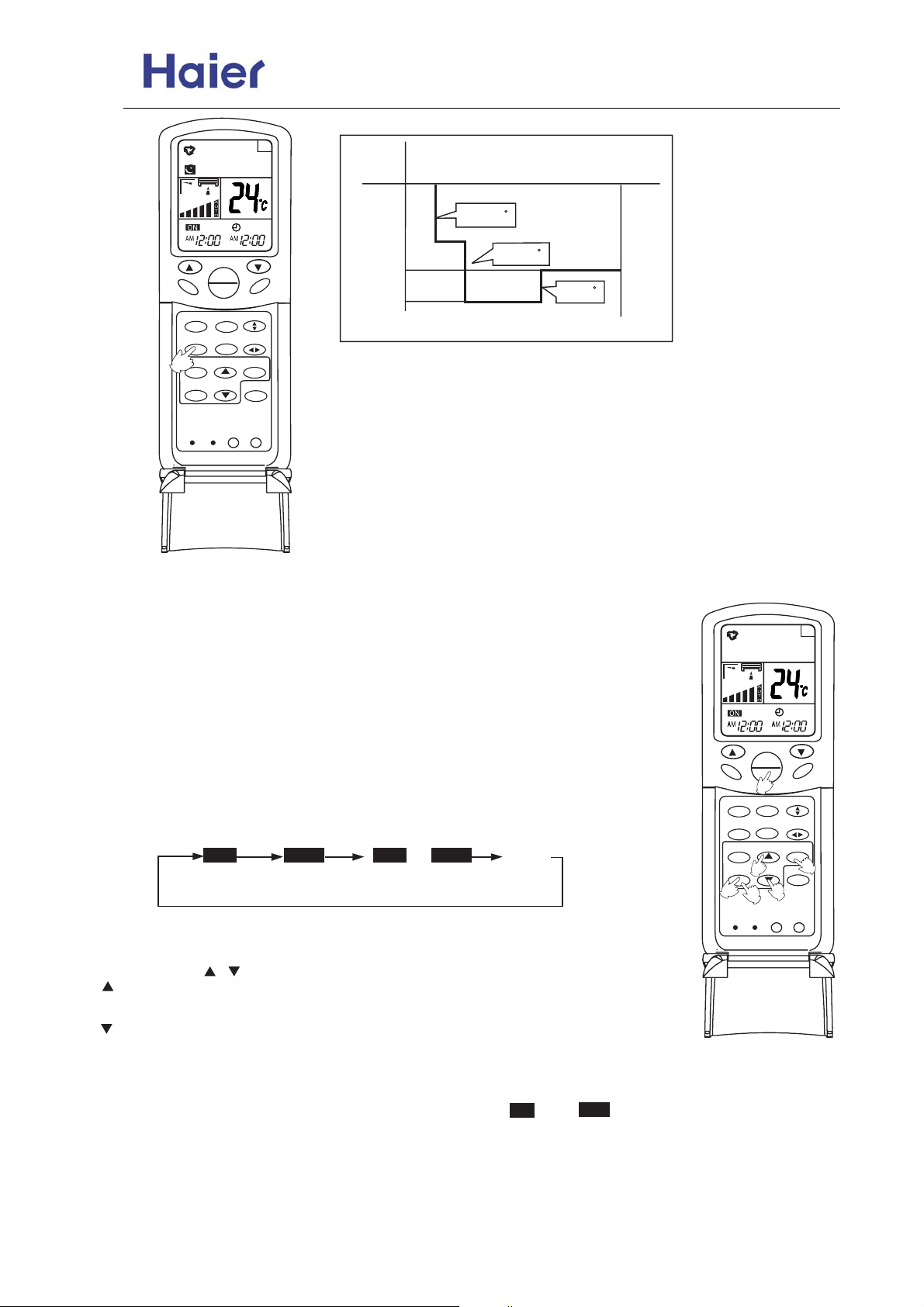
Commercial Air Conditioner Model: AU18/222XFERA
AS072/092/122XVERA
A
Set the
temperature
Close down
the machine
HEALTH
RESET
MODE
SLEEP
CLOCK
TIMER
TEMP
ON
OFF
HEALTH AIRFLOW
FRESH
CODE
SWING
SET
STERILIZE
LOCKLIGHT
1 hour
FAN
The Sleep running starts
Drop for 2 C
1 hour
Drop for 2 C
3 hours
In heating
About 3 hours
Raise 1 C
The Sleep running stops
TIMER ON/OFF operation
Remote control unit
TIMER operation
Set Clock correctly before starting Timer operation (refer to page 2)
You can let unit start or stop automatically at following times: Before you wake
up in the morning, or get back from outside or after you fall asleep at night.
TIMER ON/OFF
(1) After unit start, select your desired operation mode.
Operation mode will be displayed on LCD.
(2) TIMER mode selection
Press TIMER button to change TIMER mode.
Every time the button is pressed, display changes as follows:
Remote
controller
AM
12:00
TIMER ON
PM
12:00
TIMER OFF
AM
12:00
TIMER ON-OFF
PM
12:00
Select your desired TIMER mide (TIMER ON or TIMEROFF) ON or OFF will flash.
ON ONOFF OFF
BLANK
HEALTH
2
MODE
SLEEP
CLOCK
TIMER
RESET
TEMP
ON
OFF
1
HEALTH AIRFLOW
FRESH
3
4
CODE
5
SWING
SET
STERILIZE
LOCKLIGHT
A
FAN
6
(3) Timer setting
Press HOUR / button.
Every time the button is pressed, time increases 1 min, If button is kept
pressed, time will change quickly.
Every time the button is pressed, time decreases 1 min, If button is kept
pressed, time will change quickly. Time will be shown on LCD. It can be adjusted
within 24 hours.
(4) Confirming your setting
After setting correct time, press SET button to confirm, " " or " " stops flashing.
ON
OFF
Time displayed: Unit starts or stops at x hour x min (TIMER ON or TIMER OFF)
Timer mode indicator on indoor unit lights up.
-43-
Page 44
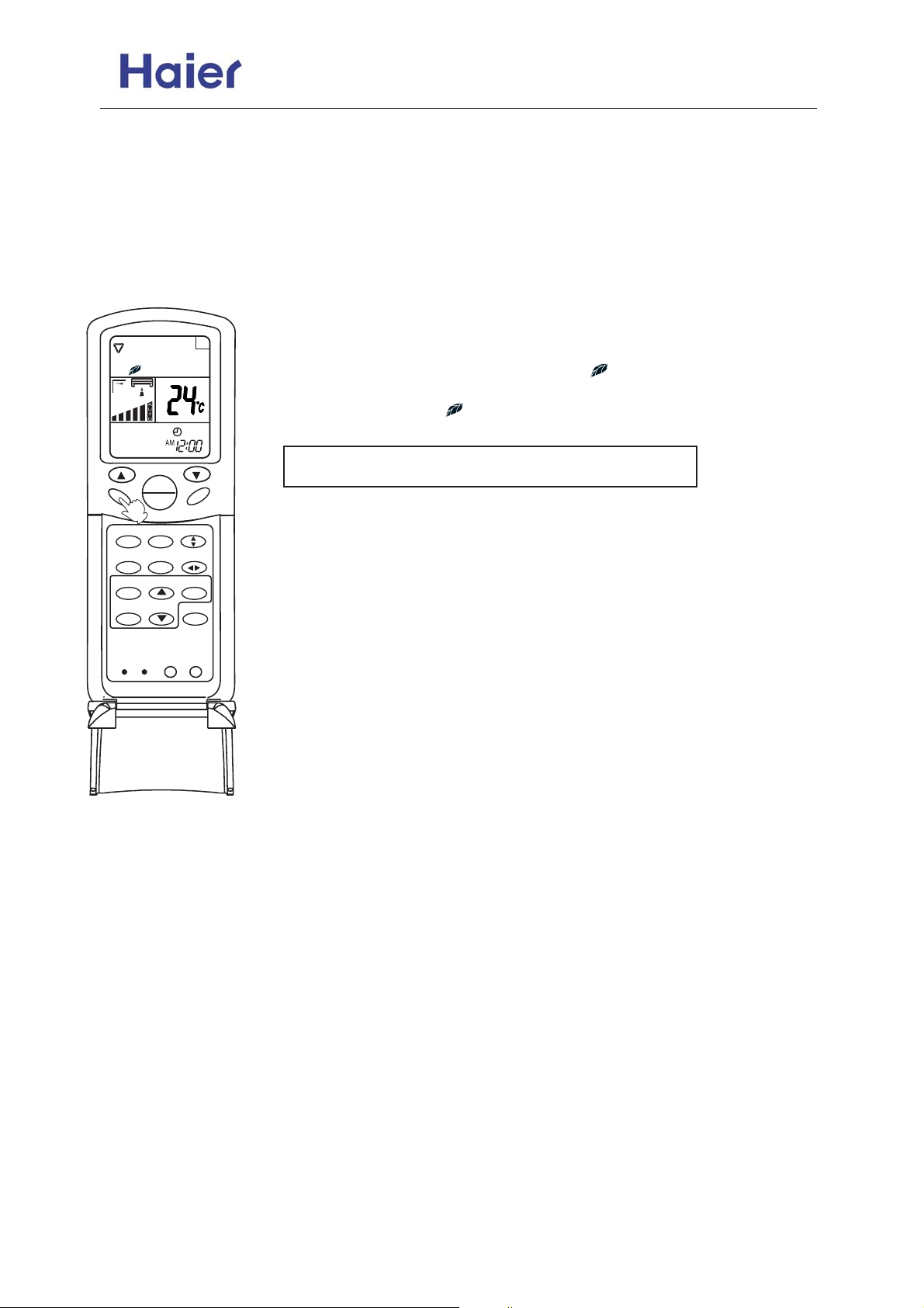
Commercial Air Conditioner Model: AU18/222XFERA
AS072/092/122XVERA
To cancel TIMER mode
Just press TIMER button several times until TIMER mode disappears.
Hints
After replacing batteries or a power failure happens, Time setting should be reset.
Remote controller possesses memory function when use TIMER mode next time, just Press SET button
after mode selecting if timer setting is the same as previous one.
Health & Fresh Air operation
HEALTH
RESET
MODE
SLEEP
CLOCK
TIMER
1
HEALTH AIRFLOW
CODE
TEMP
ON
OFF
FRESH
LIGHT
SWING
SET
STERILIZE
LOCK
A
Health operation
After turning on the unit and set the desired working mode. Press the
Health button, the LCD will display " ", the unit begins health
operation (start the negative ion generation device). Press the Health
button again, the " " displayed on the LCD disappears, health
operation is cancelled (turn off the negative ion generation device).
Note: When indoor fan motor does not work, the unit will
automatically turn off negative ion generation device.
FAN
About Health operation
After the start of Health operation, the negative ion generator will generate
large amount of negative ion, which can effectively balance the amount of
positive & negative ion in the air and has the bacteria-killing and
accelerating the dust deposition of the room to make the room air fresh and
healthy.
-44-
Page 45
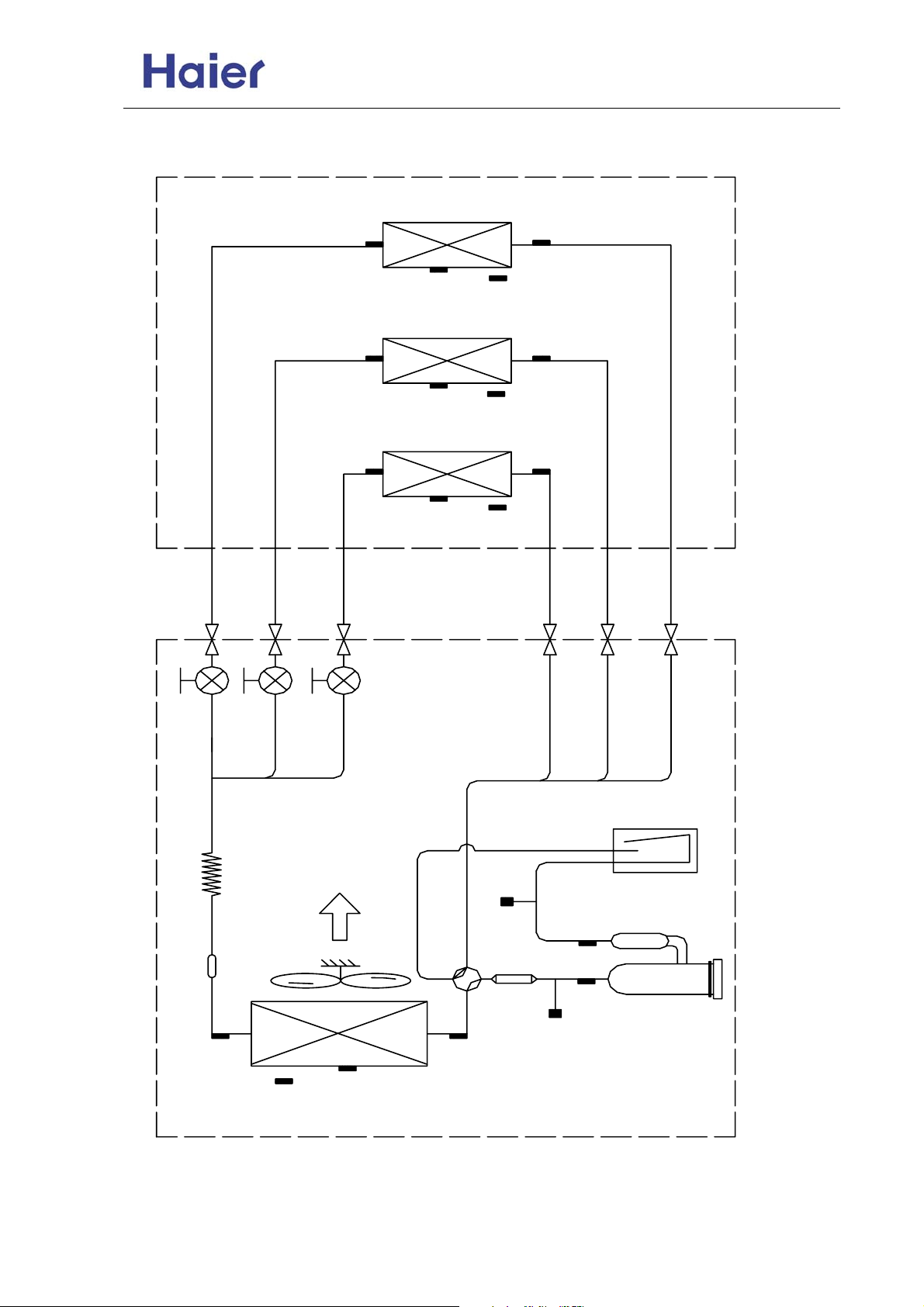
Commercial Air Conditioner Model: AU18/222XFERA
AS072/092/122XVERA
8. Refrigerant Diagram
Tc2A
C
Tc1
WAY - A
WAY - B
Tc2B
Tc2C
WAY - C
TmATmB
TmC
TaiA
Tc1D
TaiB
Tc1C
TaiC
PMV-A
PMV-B
PMV-C
CAPILLARY
ACCUMULATOR
4-WAY
VALVE
LP SWITCH
Ts
STRAINER
Td
Te
TOCI
Tc
Tao
MUFFL ER
HP SWITCH
HEATER
COMPRESSOR
-45-
Page 46
Commercial Air Conditioner Model: AU18/222XFERA
AS072/092/122XVERA
1 Heater 220V, 35W Heat up the compressor when system stops to avoid liquid compressing and liquid flood-back
No. Main Part Nam e Speci ficati on For what purpose?
2 Compressor dc inv erter Drive the system to realize the refrigerant circulation
Main part explanation:
For target SH control and high discharge temprature protection
@
50K@80
3 Td sensor
4 HP switch 4.5 / 3.7Mpa Cut off the system when discharge pressure is too high to protect system
To calculate the temperature difference between the inlet and outlet of the indoor unit to control the
For target super heating control when heating
For high pressure/ frequency/ outdoor fan speed control when cooling
For target frequency range and heater control
For defrost operation and low pressure control when heating
@
@
@
@
10K@25
10K@25
23K@25
10K@25
5 4-WAY valve / Cooling / heating swtiching
6 Toci sensor
7 Tc sensor
8 Tao sensor
9 Te sensor
10 PMVs 1.5mm, 500PLS Refrigerant distributioin and target SH(cooling) and SC(heating) control
11 LP switch 0.05 / 0.15Mpa Cut off the system when suction pressure is too low or system serious leakage to protect system
To calculate the target SH and SC, and control the start up of the compressor
To calculate the real super heating value together with Tout to operate the PMVs, for target
compressor frequency control and low pressure protection when cooling
To calculate the real super cooling value together with Tin to operate the PMVs, for target compressor
frequency control and high pressure control when heating
To calculate the real super heating value together with Tin to operate the PMVs
@
@
10K@25
10K@25
12 Accumulator 1.5L Separate the liquid refrigerant and gas refrigerant in suction line to avoid liquid flood-back
13 Ts sensor
14 Tc2
@
10K@25
15 Tm
@
10K@25
16 Tc1
target rrequency and THERMO. ON or OFF.
@
23K@25
17 Tai
-46-
Page 47
Commercial Air Conditioner Model: AU18/222XFERA
AS072/092/122XVERA
9. Electrical Control Functions
Outdoor electric control functions:
1. Switch setting and functions:
2. Defination of 4-bit dip switch SW5 on failure indicator board:
3. Main control functions
3.1 Refrigerant diagram
3.1 Refrigerant diagram
No Item
A8
C1
C2
C3
C4
C8
1 2 3 4 Defination
OFF OFF OFF OFF State when out of factory (normal state)
OFF ON OFF OFF
ON OFF OFF OFF
OFF OFF ON OFF
Set in factory
Switch function: SW5-1---outdoor fan motor selection, ON: DC fan motor; OFF: AC fan
motor
Switch function: SW5-2---defrosting data setting, ON=6degree, OFF=8degree (set
when out of factory).
For the place where is easy to frost, it is 6 degree; for the place hard to frost, it is 8
degree.
Switch function: SW5-3,SW5-4---piping length selection, the set data is M when out of
factory.
S(SW5-3=OFF SW4=ON) L(SW5-3=ON SW4=OFF)
- (SW5-3=ON SW4=ON) M(SW5-3=OFF SW4=OFF)
Switch function: SW5-5,SW5-6---outdoor horse power selection (for different outdoor,
the current limitation is different too. The corresponding selection must be taken, or
the module protection will occur. )
2HP(SW5-5=OFF SW5-6=ON) 2.5HP(SW5-5=ON SW5-6=OFF)
3HP (SW5-5=ON SW5-6=ON) 3.5HP(SW5-5=OFF SW5-6=OFF)
Switch function: SW5-7,SW5-8:
SW5-7-pre-set, set as OFF when out of factory.
SW5-8-silent operation function, ON---available, OFF---not available (set when
out of factory)
When it is ON, the max. fan speed is Class-6, and the max. running frequency is 10Hz.
Set in factory
Compulsory cooling: frequency 60HZ, outdoor fan motor Class-7, fixed open angle
300, the others are in normal state
Compulsory heating: frequency 50HZ, outdoor fan motor Class-5, fixed open angle
300, the others are in normal state
Rated operation: auto changeover for cool/heat, max. frequency 53HZ(E) in cooling,
and max. frequency 72HZ(E) in heating, the frequency is set automatically in other
states.
-47-
Page 48
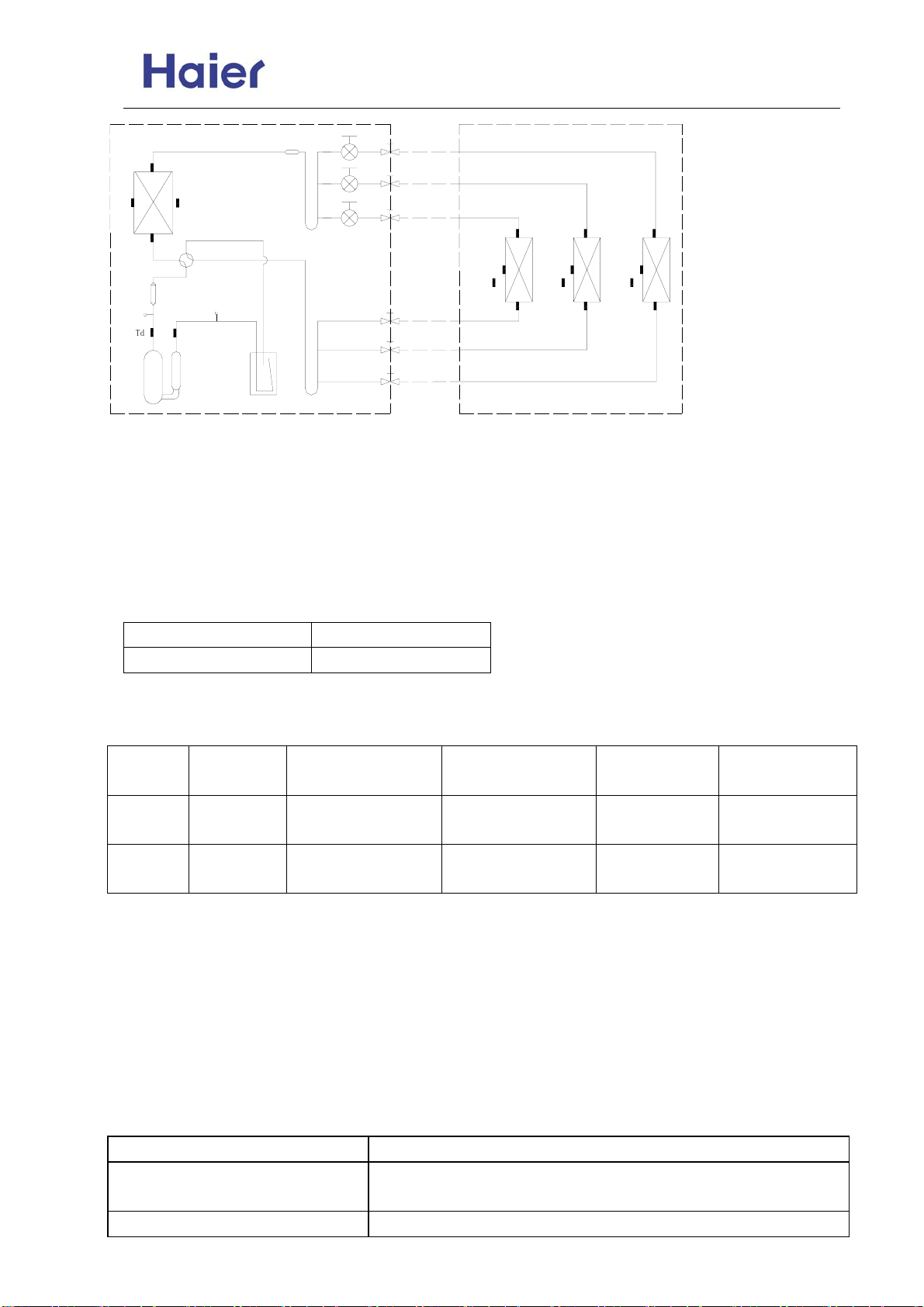
Commercial Air Conditioner Model: AU18/222XFERA
AS072/092/122XVERA
Te
Tc
HPSW
Toci
Tao
TinC
TmC
L
P
S
W
T
d
Ts
TaiC
TouC
TaiB
TmB
TinB
TouB
TinA
TmA
TaiA
TouA
3.2 Outdoor frequency control
3.2.1 Compressor running frequency range: 20~90RPS
3.2.2 Defination of high-efficiency operation and its frequency control
In order to meet the cooling request at high ambient temperature and the heating request at low ambient
temperature, we set the high-efficiency operation.
Entering condition: cooling mode, Tao≥33℃(E), heating mode, Tao≤5℃(E).
3.3 Electronic expansion valve (EEV) control
3.3.1 Electronic characteristic
Max. open angle 500 pulse
Driving speed PPS
3.3.2 Initialization of EEV
EEV driving speed: open direction: 32MS; close direction: 32MS
3.3.3 Open angle limitation of EEV
Unit stop Adjustable upper
Cool/dry
heat
5(E) 450(E)
60(E) 450(E)
limitation
3.3.4 Standard open angle control
In Cool/Dry mode, standard open angle: outdoor ambient temp.≥20℃, 250 pulse(E);
In Heat mode, standard open angle: outdoor ambient temp.≥10℃, pulse (E);
Outdoor ambient temp.<20℃, 210 pulse(E);
outdoor ambient temp.<10℃, 210 pulse (E).
3.3.5 When discharging temp. Td is too high, modify the EEV angle.
In order to cooperate the compressor discharging temp. over high protection, the system will enlarge the
EEV open angle. Within 5 minutes after compressor starts up, it will not modify. The detecting period is 30
seconds.
Cooling mode Indoor modification angle
100℃<discharging temp.
+50degree/30seconds, it will stop until up to the max. permitted
90℃< discharging temp.<=100℃
Thermostat ON Thermostat
OFF
standard open
5(E) 80(E)
angle+tolerance
standard open
60(E) 80(E)
angle+tolerance
opening angle
Keep the angle
Adjustable lower
limitation
-48-
Page 49
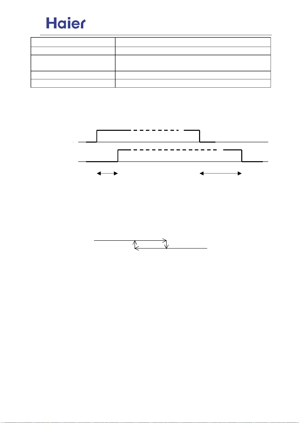
Commercial Air Conditioner Model: AU18/222XFERA
AS072/092/122XVERA
100℃< discharging temp.
90℃< discharging temp.<=100℃
3.4 4-way valve control in heating
Protection when 4-way valve can not reverse in heating:
10 minutes later after compressor startup, if indoor coil average temp. is below 15degree and keeps for 1
minute, the unit will stop and occur the 4-way valve protection.
compressor ON
OFF
4-way valve ON
OFF
15s(E) 2minutes and 55s
3.5 Electric heater control
If compressor has not run for a long time, the refrigerant will deposit on the bottom of compressor and mix
with the refrigeranr oil. When re-startup, because low pressure reduces, refrigerant will be segregated
from the refrigerant oil and cause soam in the oil, which will make compressor exhaust a lot of oil.
Therefore please stop heating the compressor bottom to ensure the low pressure in startup period should
not go down greatly.
Ambient temp. TA≤27degree, when compressor stops, the electric heater will be electrified.
When TA≥32degree, or compressor running, the electric heater will be off.
Heater ON
OFF
Ambient temp. TA(℃) 27 32
3.6 Control of liquid spray valve SV2:
According to the compressor discharging temp., open or close the SV2.
①Control condition:
A. In every mode (including defrosting and oil return operation), the control can work.
B. In 3 minutes after compressor startup, ignore the abnormal compressor suction and discharging value.
②3 minutes later after compressor startup, according to the discharging temp., the following procedure
will be taken:
Td≤90℃, SV2 close;
Td>110℃, SV2 open.
③In 150 seconds when compressor stops, in order to keep the system in balanc, please open the liquid
spray valve SV2. 150 seconds later after compressor stops, SV2 close.
3.7 Control of defrosting in heating
In heating mode, defrosting temp. sensor will check the frosting condition of outdoor heat exchanger and
make defrosting control.
3.7.1 Enter condition:
①In heating mode, if the compressor has run for 10 minutes continously and run for 45 minutes in all, the
system will measure the defrosting temperature sensor Te and outdoor ambient temp. sensor TA, if the
below condition can be met for continous 5 minutes, the unit will enter defrosting operation:
<=90℃
Heating mode Indoor modification angle
<=90℃
-5degree/30seconds, and reduce to 0 degree gradually
+50degree/30seconds, it will stop until up to the max. permitted
opening angle
Keep the angle
-5degree/30seconds, and reduce to 0 degree gradually
-49-
Page 50
Commercial Air Conditioner Model: AU18/222XFERA
AS072/092/122XVERA
According to SW2, the setting is as follow: in the place easy to frost, it is H; when out of factory, it is M.
②Defrosting entering condition: -15℃≤C×TA-α≤-2℃
③Stop and Pause condition of compressor running accumulative time in heating mode:
Checking Stop: running operation changes from heating to cooling.
Checking Pause: thermostat OFF, or the unit stops.
3.7.2 Cancel condition:
It will take the max. 10 minutes from beginning defrosting to quit it. Te sensor will measure the condition of
outdoor heat exchanger, if the temp. is over 7℃ for 60 seconds in all or is up to 12℃ for 30 seconds in all,
the defrosting will be over.
3.7.3 Compulsory defrosting control
Enter condition: in heating mode, after receiving the compulsory defrosting signal from indoor unit, the unit
will perform the compulsory defrosting operation.
Cancel condition: Te≥12℃ and keep for 1 minute or the defrosting time is over 10 minutes.
The manual defrosting signal of indoor unit will remain until the outdoor enters defrosting mode.
Note: When outdoor compressor not running, the unti still can enter manual defrosting, but it will comply
with the 3-minute protection of compressor.
Herein: C:TA<0℃,C=0.8 TA≥0℃,C=0.6
Jumper
selection
α(℃)
M(out of factory) H
Te≤C×TA-α
8(E) 6(E)
-50-
Page 51
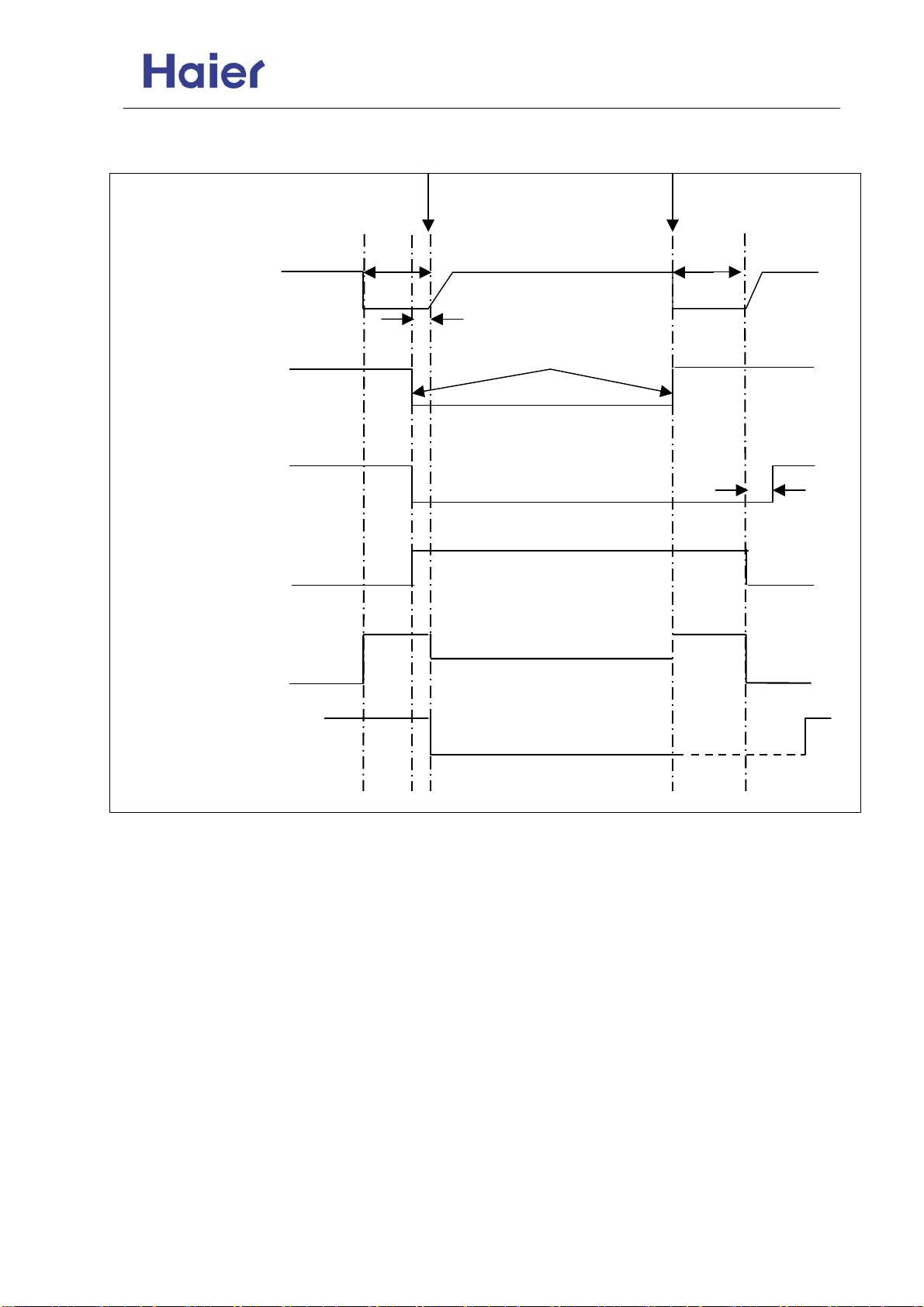
Commercial Air Conditioner Model: AU18/222XFERA
AS072/092/122XVERA
3.7.4 Defrosting operation flow chart
fixed frequency indicated FQY 60s defrosting FQY 80 Hz(E) 60s soft startup
compressor
0HZ 0HZ
5s
OFF
OFF 15s
ON
Spray valve SV2 OFF
450-pulse 450-pulse
350-pulse(E)
all indoor motors ON
outdoor motor ON send defrosting signal to indoor Auto
4-way valve ON
all EEVs auto open angle auto open angle
OFF anti-cold air function
beginning end
-51-
Page 52
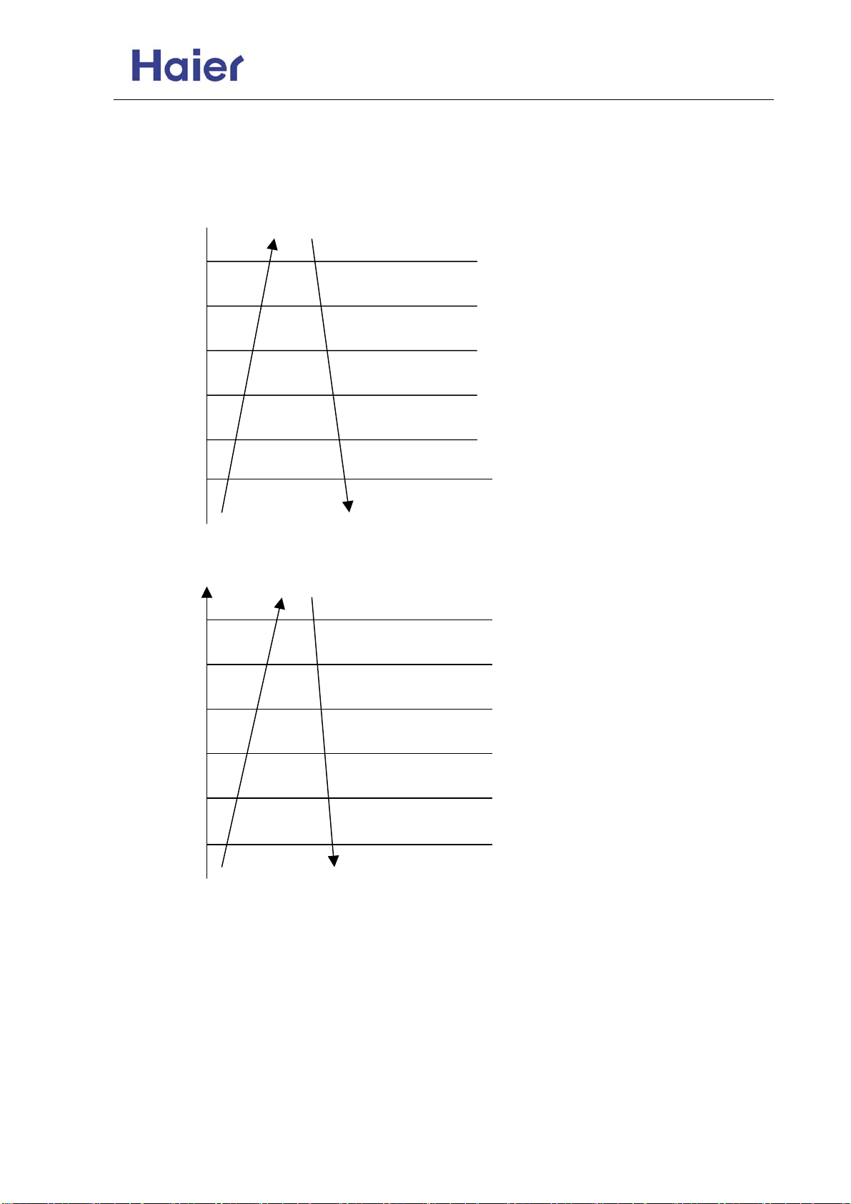
g
g
p
Commercial Air Conditioner Model: AU18/222XFERA
AS072/092/122XVERA
3.8 Frequency control when Td is too high
Purpose: make compressor frequency control if the discharging temp. is too high, to lower the discharging
temp. efficiently and ensure the system can run normally.
3.9 Frequency control when there is CT over current protection
120℃
. TD
115℃
tem
in
110℃
105℃
Dischar
100℃
95℃
1.0 I
0.95I
0.93I
0.90I
0.88I
0.85I
If keeping for 10s, the unit stops, 3 minutes later, the unit can
re-startup. If in 60 minutesthe unit occurs alarm for 3 times, the
failure can be eliminated.
Reduce FQY rapidly 2HZ/S
Reduce FQY rapidly 1HZ/S
Reduce FQY slowly 1HZ/10S
Remain FQY
Increase FQY slowly 1HZ/10S
Stop immediately, if abnormal stop 3 times in 1 hour, the
unit will stop and alarm.
Reduce FQY rapidly 2HZ/S
Reduce FQY rapidly 1HZ/S
Reduce FQY slowly 1HZ/10S
Remain FQY
Increase FQY slowly 1HZ/10S
-52-
Page 53
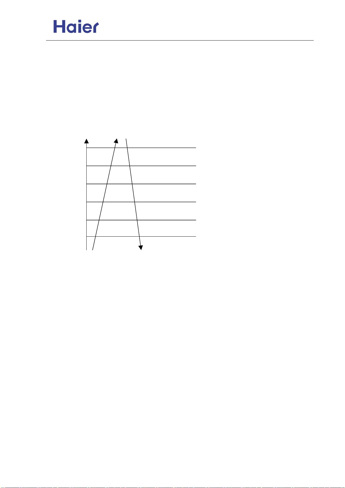
Commercial Air Conditioner Model: AU18/222XFERA
AS072/092/122XVERA
3.10 High pressure protection
When the input signal of pressure switch is high level:1, that shows there is no protection.
When the input signal of pressure switch is low level: 0 for 1 minute, that shows high pressure protection
works. At this time, compressor stops, outdoor will send the alarm signal. The alarm can be resumable. If
in 60 minutes, the failure occurs 3 times, the failure can be confirmed and send failure code to indoor.
Meanwhile, by controling the max. condensate temp. Tc (cooling) or TmAVE (heating), please confirm as
follow:
In nominal cooling/dry/heating mode, high pressure can be controlled by limiting the max. frequency.
3.11 Low pressure protection
(1) When compressor is running, if output signal of low pressure switch is low level: 0 for 1 minute
(2) When compressor no running, if output signal of low pressure switch is low level: 0 for 30 seconds
·When unit stops, the reason that system still checks the low pressure : in a long time stop, make
·The reason that low pressure switch action time is 30 seconds: when compressor stops, low pressure
does not change, so it will be shorter than the set time in operation.
(3) When compressor starts up, in 8 minutes, low pressure switch signal will be shielded.
(4) In defrosting, low pressure switch will be shielded.
(5) In oil return procedure, low pressure switch will be shielded.
(6) In the refrigerant discharging procedure after the oil return in cooling is over, low pressure switch will
be shielded.
In addition, the system will control low pressure through the evaporator temp. TE to realize the low
pressure protection function.
Condensing temp.
70℃
68℃
66℃
64℃
62℃
60℃
Keep for 5 seconds, stop to alarm, after 3-minute standby, the
unit can restartup. In 3 minutes it occurs 3 times continously,
unit will stop to alarm and the failure can be resumed after being
electrified again.
Reduce FQY rapidly 2HZ/S
Reduce FQY rapidly 1HZ/S
Reduce FQY slowly 1HZ/10S
Remain FQY
Increase FQY slowly 1HZ/10S
continously, compressor will stop,outdoor alarms. The alarm can be resumable. If in 60 minutes, the
failure occurs 3 times, the failure can be confirmed and send failure code to indoor.
continously, alarm will occur.
protection for the compressor on the condition of great refrigerant leakage.
-53-
Page 54
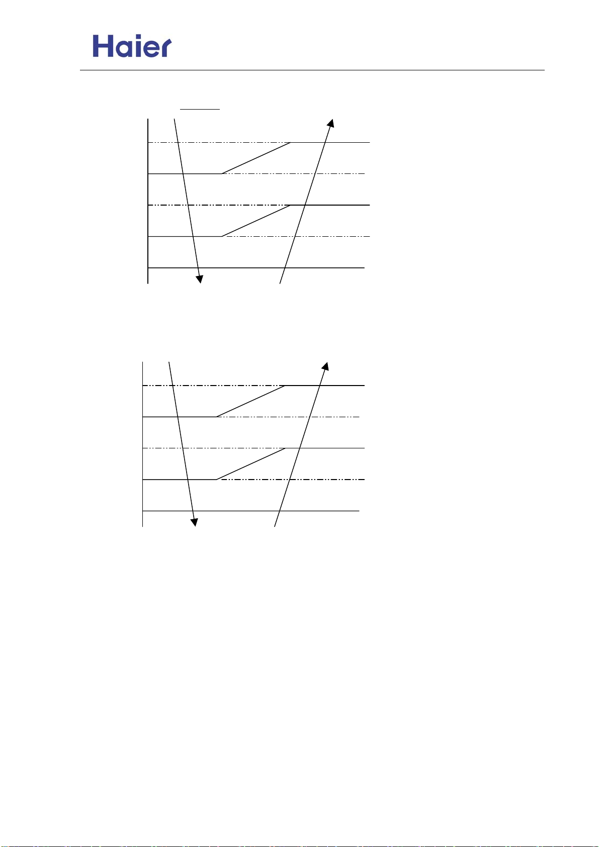
t
Commercial Air Conditioner Model: AU18/222XFERA
AS072/092/122XVERA
In cooling, confirm through Tc2AVE:
In heating, confirm through defrosting temp. Te:
Te
If the failure is not confirmed as the permanent protection, outdoor will not send failure code to indoor, and
indoor will not alarm.
TinAVE
-30℃
-35℃
-40℃
-45℃
-50℃
-25℃
-30℃
-35℃
-40℃
-45℃
Normal operation
Min. running FQY 20HZ
SV2 OFF & 20HZ
SV2 ON & 20HZ
Keep for 5 seconds, unit stops and alarm
occurs. 3 minutes later, restart up. If i
occurs 3 times in 1 hour, it will always
alarm and stop, electrify again and failure
will be cleared.
Normal operation
Min. running FQY 20HZ
SV2 OFF & 20HZ
SV2 ON & 20HZ
Keep for 5 seconds, unit stops and
alarm occurs. 3 minutes later, restart
up. If it occurs 3 times in 1 hour, it will
always alarm and stop, electrify again
and failure will be cleared.
-54-
Page 55
Commercial Air Conditioner Model: AU18/222XFERA
AS072/092/122XVERA
Indoor electric control functions:
Note: The following functions are applicable for the unit in normal state.
1. Parameter input:
1.1 Analog data input:
1.1.1 Indoor temperature sensor input (TA): 1-way, 23KΩ at 25℃
1.1.2 Indoor coil outlet temp/inlet temp (TC1: gas pipe, TC2: liquid pipe): 2-way, 10KΩ at 25℃
1.1.3 Indoor middle coil temp. (Tm): 1-way, 10KΩ at 25℃.
1.2 Functional switch setting:
1.2.1 Central control address setting and indoor communication address setting:
8-way (SW01), the detailed definition is as follow: 0-OFF, 1-ON
AS072~AS122XVERA:
SW01
[1] [2] [3] [4] [5] [6] [7] [8]
-- 0 0 0 0 0 0 0 Central control address=1
-- 0 0 0 0 0 0 1 Central control address =2
-- 1 1 1 1 1 1 0 Central control address =127
-- 1 1 1 1 1 1 1 Central control address =128
0 -- -- -- -- -- -- -- Indoor communication address set by
1 -- -- -- -- -- -- -- Indoor communication address set by dip
SW02
[1] [2] [3] [4] [5] [6] [7] [8]
0 0 -- -- -- -- -- -- AS072 capacity selection
0 1 -- -- -- -- -- -- AS092 capacity selection
1 0 -- -- -- -- -- -- AS122 capacity selection
-- -- 0 0 -- -- -- -- LCD display board (LCD remote
-- -- 1 1 -- -- -- -- LED display board (LED remote
-- -- -- -- 0 -- -- -- Room card function valid
-- -- -- -- 1 -- -- -- Room card function unavailable
-- -- -- -- -- 0 0 0 Indoor communication address 1
-- -- -- -- -- 0 0 1 Indoor communication address 2
-- -- -- -- -- 0 1 0 Indoor communication address 3
-- -- -- -- -- 0 1 1 Indoor communication address 4
-- -- -- -- -- 1 0 0 Indoor communication address 5
-- -- -- -- -- 1 0 1 Indoor communication address 6
-- -- -- -- -- 1 1 0 Indoor communication address 7
-- -- -- -- -- 1 1 1 Indoor communication address 8
---- ----
remote controller
switch
receiver)
receiver)
-55-
description
description
Page 56
Commercial Air Conditioner Model: AU18/222XFERA
AS072/092/122XVERA
Note: The above dip switches are correlative to the system security, so please confirm the
conformity between the unit and the dip switch. The incorrect dip switch setting will result
in the system wrong operation or the wrong failure diagnosis.
2. Cooling operation
2.1 The set temperature in cooling: TS=the set temp. on remote controller
2.2 After cooling startup, indoor unit will send the frequency code to outdoor according to
the temp. difference between the set temp. and the ambient temp.
3. Heating operation
3.1 In heating operation, the set temp. TS=the set temp. on remote controller
3.2 After heating startup, indoor unit will send the frequency code to outdoor according to
the temp. difference between the set temp. and the ambient temp.
4. Dry operation
Room temp.-(set temp.+ tolerance) >2℃, indoor operation is identical to the cooling
operation, and sends the cooling operation signal to outdoor.
Room temp.-(set temp.+ tolerance) ≤2℃, indoor unit sends the dry operation signal to
outdoor.
Room temp. <16℃, indoor unit stops running and sends stop-unit signal to outdoor.
5. Fan operation
Indoor fan motor will run as the fan speed set on the remote controller and indoor unit will
send the stop-unit signal to outdoor.
6. Auto operation
If the unit enters Auto mode for the first time, the system will adjust the operation mode
according to the room temp. and the set temp.
When room temp.≥set temp., entering cooling mode;
When room temp.<set temp., entering heating mode.
Mode conversion will be confirmed after compressor has stopped for 15 minutes.
7. Abnormal operation
When outdoor modes from the request of indoor unit conflict, the one entering firstly will
take priority.
After indoor receives the ON command from remote controller, it will firstly confirm the
outdoor current operation mode. If they are the same mode, indoor unit will run as the
request of remote controller. If they are different modes, the system will forbid to operate,
and indoor will keep the OFF mode. After setting on remote controller, if the buzzer
sounds two times, that shows abnormal operation. Indoor will run until the outdoor mode
and the requested mode of remote controller are the same.
8. Compensation control for discontinuous operation
After the unit starts up in cooling/heating mode, in 3 minutes, the compressor run/stop will
not be controlled by the room temp., but after changing the set temp., if compressor stop
condition can be met, the system will stop compressor immediately.
9. Anti-cold air control
In heating mode, after compressor startup, the system will control indoor fan motor
according to indoor coil temperature. At the beginning of startup, the indoor fan motor can
run only when indoor mid-coil temp. is over 28℃(±2℃). When indoor mid-coil temp.
goes down to 18℃(±2℃), indoor fan motor will stop running.
-56-
Page 57
Commercial Air Conditioner Model: AU18/222XFERA
AS072/092/122XVERA
In defrosting period, indoor fan motor will stop running;
In heating mode, if unit shutoff, indoor fan motor will stop after running for 30 seconds at
super low speed.
Note: The above temp. point has taken fuzzy control, and has tolerance ±2℃ according
to the different state.
10. Fan motor control in defrosting
10.1 On receiving outdoor defrosting signal, indoor unit will stop after blowing remaining
heat at slow speed for 20 seconds.
10.2 In defrosting period, indoor fan motor stops running.
10.3 Defrosting is over, and indoor motor will run as anti-cold air state.
11. Blowing remaining heat operation
When the unit shuts off in heating mode or the thermostat is OFF, indoor motor will stop
running after running at super low speed for 30 seconds.
12. Anti-freezed protection (invalid in heating mode)
When compressor has run for over 5 minutes, to prevent indoor evaporator freezing (in
cooling/dry mode), if indoor mid-coil temp. is below 0 degree, compressor will stop. When
indoor mid-coil temp. is over about 10 degree, the unit can run. After compressor has
stopped for 3 minutes, the unit can re-start up.
Note: The above temp. point has taken fuzzy control, and has tolerance ±1℃ according
to the different state.
13. Overload protection in heating mode
It is valid only in heating mode, if indoor mid-coil temp. is over about 65 degree
continuously for 10 seconds, indoor will stop; while when indoor mid-coil temp. is below 52
degree, indoor will resume.
Note: The above temp. point has taken fuzzy control, and has tolerance ±1℃ according
to the different state.
14. Timer operation
TIMER ON/TIMER OFF/TIMER ON/OFF. Timer will count according to the time difference
between the TIMER clock and the present clock. In TIMER state, TIMER indicator will be
ON.
15. SLEEP function
In cooling/dry mode, after running for 1 hour, the set temp. will increase 1℃, another 1
hour later, the set temp. will increase 1℃ again, then 6 hours later, it will stop.
In heating mode, after running for 1 hour, the set temp. will reduce 2℃, another 1 hour
later, the set temp. will reduce 2℃ again, then 3 hours later, the set temp. will increase 1
℃, and another 3 hours, it will stop.
16. Auto-restart function
In 5 seconds, press SLEEP button 10 times continuously, the buzzer will sound 4 times
and enter auto-restart function. In 5 seconds, press SLEEP 10 times continuously, the
buzzer will sound twice and quit auto-restart function. If no SLEEP button, press SWING
as the same method.
17. Setting indoor unit number
In OFF state, press emergency switch until 15 seconds later, the buzzer sounds 4 times,
indoor will enter the indoor unit number setting state, the set method is as follow:
-57-
Page 58
Commercial Air Conditioner Model: AU18/222XFERA
AS072/092/122XVERA
Press ON/OFF button (from OFF mode to ON mode), the times of SLEEP button to be
pressed is the set unit number , then press ON/OFF button to quit unit number setting state,
at this time, indoor unit is at OFF state, the display panel will display this unit number. For
example, press SLEEP button once, it is No. 1 unit; press twice, it is No. 2 unit, and so on.
In OFF state, press emergency switch until 15 seconds later, the buzzer sounds 5 times,
the display panel will display this unit number and you can check if there are repeated
numbers.
18. Setting method of temperature compensation
Set the temperature compensation in heating mode with the remote controller. No
compensation in cooling mode. In 24℃ heating mode, press SLEEP button 8 times
continuously, indoor buzzer sounds 5 times, that shows temp. compensation works.
Switch on the unit in heating mode by the remote controller, press TEMP button to set the
set temp., so temperature compensation=the current set temp. - 24℃. For example, if the
set temp. is 24℃, the temp. compensation is 0℃; if the set temp. is 25℃, the temp.
compensation is 1℃. Please do not set the minus temp. compensation, that is to say the
min. temp. compensation is 0℃.
If setting is finished, press ON/OFF button, then indoor buzzer will sound 4 times, that
shows the unit quits the temp. compensation.
-58-
Page 59
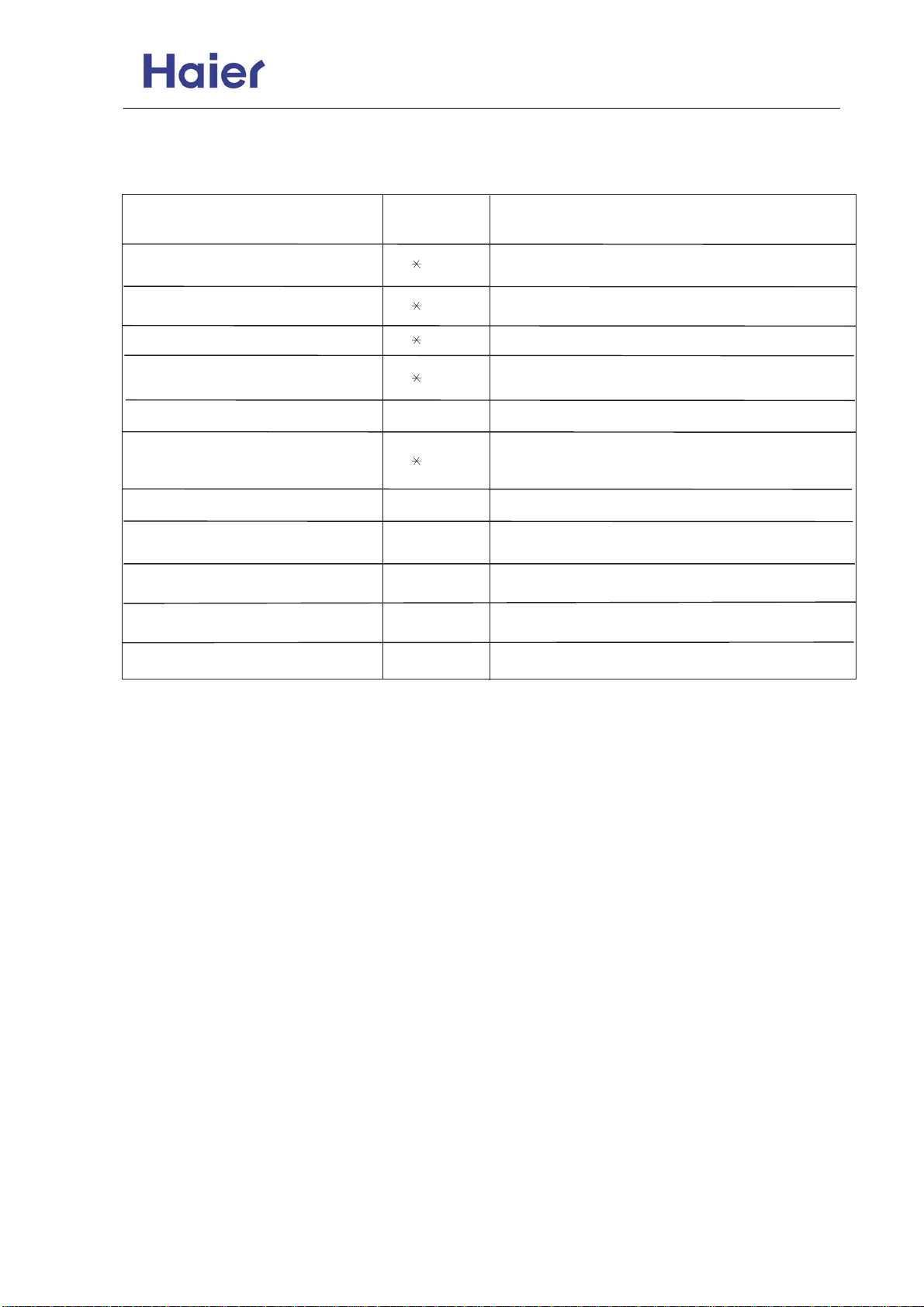
Commercial Air Conditioner Model: AU18/222XFERA
AS072/092/122XVERA
10. Diagnostic information and troubleshooting
Indoor failure code
TROUBLE SHOOTING
Faulty temperature sensor Tai 1
Faulty temperature sensor Tc1 2
Faulty temperature sensor Tc2 3
Faulty temperature sensor Tm 4
Faulty EEPROM on indoor
Abnormal communication
between indoor and outdoor unit
Indoor unit address repeated 9 Wrong setting of indoor unit address
Central control address repeated 10
Faulty indoor unit fan motor 11
Faulty driver of indoor unit
Malfunction on outdoor unit 20
FAILURE CODE
Sensor disconnected, or broken, or at wrong
Sensor disconnected, or broken, or at wrong
position, or short circuit
Sensor disconnected, or broken, or at wrong
Sensor disconnected, or broken, or at wrong
position, or short circuit
5
6
12 Faulty indoor unit PCB
Faulty indoor unit PCB
Wrong connection, or the wires be disconnected,
or wrong address setting of indoor units, or faulty
PCB, or faulty power supply
Wrong setting of centralized control indoor unit
Fan is blocked, or the terminal is disconnected
from the PCB, or faulty indoor unit PCB
Check the outdoor unit
POSSIBLE REASONS
Note:
1. Please contact the installers or distributors when trouble happens.
2. Turn the power off and power on again, if the failure code recurs, please change the indoor unit
PCB.
3. Failrue codes maked with* are resumable.
-59-
Page 60
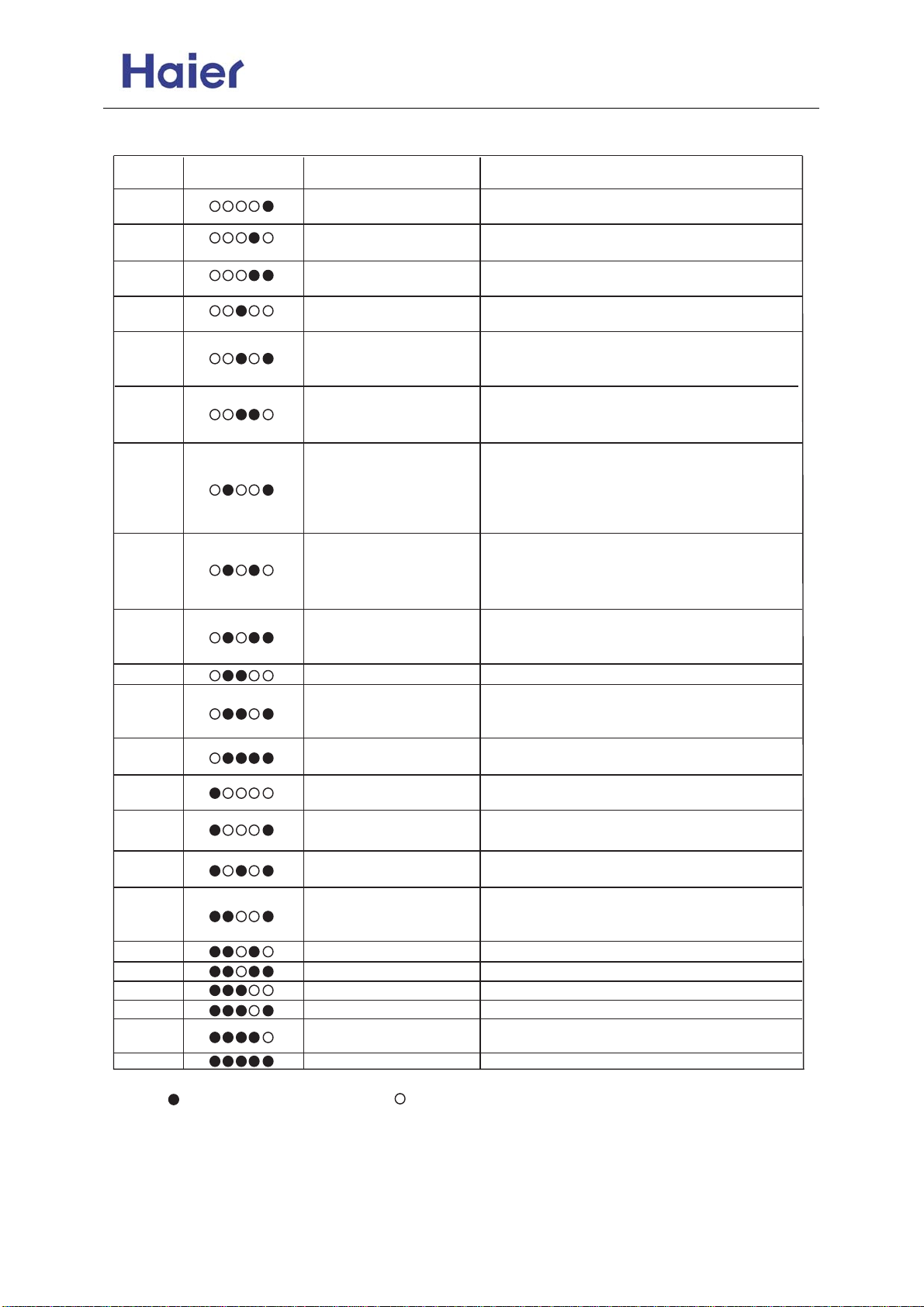
Commercial Air Conditioner Model: AU18/222XFERA
AS072/092/122XVERA
Outdoor trouble shooting
FAILURE
CODE
1
2
3
4
5
6
9
10
11
12
13
15
16
17
STATE OF
LED 5-4-3-2-1
TROUBLE
SHOOTING
Faulty defrost sensor Te Sensor disconnected, or broken, or short circuit
Faulty sensor Tao Sensor disconnected, or broken, or short circuit
Faulty sensor Ts Sensor disconnected, or broken, or short circuit
Faulty sensor Td Sensor disconnected, or broken, or short circuit
Over current of the system, or broken of the current
Input overcurrent
Abnormal communication
between indoor and outdoor
units
System high pressure
protection
System low pressure
protection
IPM protection
EEPROM fault Faulty outdoor unit PCB
Over hot protection of
compressor
DC fan motor fault
Faulty 4-way valve
switching on
Faulty sensor Tc Sensor disconnected, or broken, or short circuit
sensor,or malfunction with indoor or outdoor fan
motors, or faulty PCB.
Wrong connection, or the wires be disconnected, or
wrong address setting of indoor units, or faulty PCB,
or faulty power supply
High pressure switch is disconnected, or high
pressure switch worked, or Tc too high and faulty
outdoor fan motor when cooling, or faulty indoor fan
motors when heating, or refrigerant overabundance
Low pressure switch is disconnected, or low
pressure switch worked, or Te too low and faulty
outdoor fan motors when heating, or faulty indoor
fan motor when cooling, or refrigerant shortage
IPM over current, or short circuit, or IPM
temperature too high, or IPM input voltage too
low,or faulty SPDU.
Serious lack of refrigerant of the system, or the
ambient temperature too high, or PMVs be
blocked
Fan is blocked, or the terminal is disconnected
from the PCB
Coil of 4-way valve is disconnected, or faulty
outdoor PCB
POSSIBLE REASONS
21
25
26
27
28
29
30
31
Faulty sensor Toci Sensor disconnected, or broken, or short circuit
Abnormal communication
between main PCB and
SPDU
Compressor locked rotor Faulty compressor or SPDU
Compressor heavy vibration
Compressor lose position Faulty SPDU
Faulty compressor start Faulty compressor or SPDU
Faulty position checking
circuit
Compressor broken Faulty compressor or SPDU
Communication cables broken, or not be well
connected, or faulty main PCB, or faulty SPDU
Faulty compressor
Faulty SPDU
Take off the plastic valve cover, you can find the LEDs near to the communication terminal.
Symbol means the LED is ON. Symbol means the LED is OFF.
-60-
Page 61
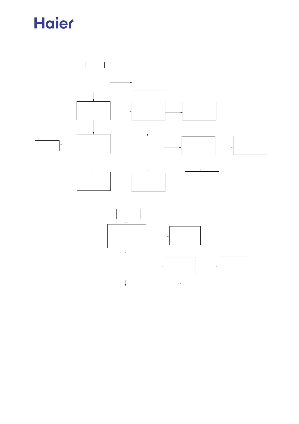
Commercial Air Conditioner Model: AU18/222XFERA
AS072/092/122XVERA
Troubleshooting:
Trouble 1: No display on the operation panel
PCB is faulty,
replace it
Trouble 2: Sensor failure
no
start
check if display
panel and the
unit matched
well
yes
if the red diode
and green diode
on indoor PCB
flash in turn
yes
check if display
panel is 12V
power supply
yes
display panel
circuit is damaged,
replace it
no
no
replace display
panel and check
again
if the power
terminal block is
220V input
check if power
wiring is in open
circuit
replace power
wiring and
check again
start
as per the wiring
diagram,check the
connection
between sensor
and PCB is correct
yes
check if sensor is in
open circuit or PCB
port is not in good
condition
yes
replace
sensor and
check again
yes
yes
no
check the terminal
block and the
no
power supply
no
check if sensor
resistor value is
correct
check if fuse is
burnt
replace the fuse
and check again
re-fix the sensor
and check again
yes
PCB is faulty
and repalce it,
check again
yes
nono
PCB is faulty,
no
replace
replace sensor
and check again
-61-
Page 62
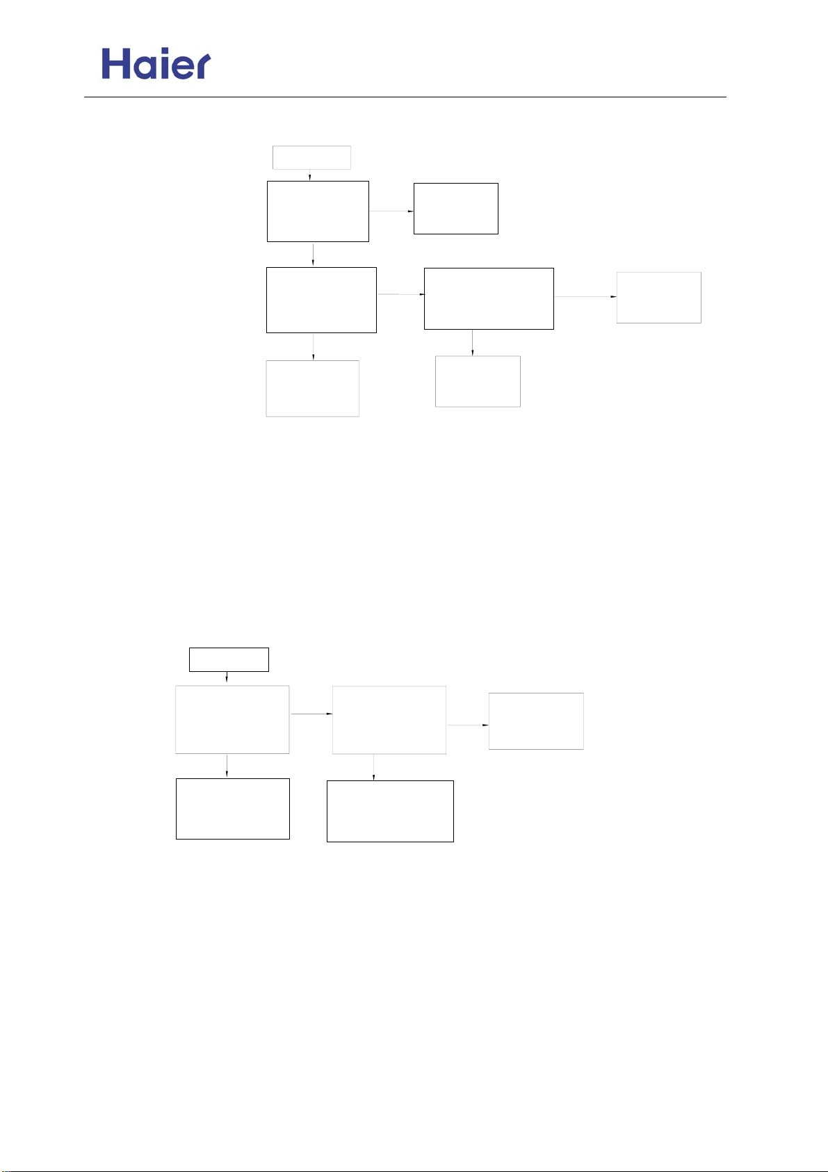
Commercial Air Conditioner Model: AU18/222XFERA
AS072/092/122XVERA
Trouble 3: Communication failure between indoor and outdoor
Trouble 4: Indoor PCB EEPROM data is wrong
1.If the failure occurs when being electrified for the first time, that shows EEPROM
damaged.
2.If the failure occurs when running, that shows EEPROM is faulty and need to be replaced.
Trouble 5: Indoor repeated unit number
1.Firstly query the unit number: switch off the unit, press SLEEP for about 15 seconds until the buzzer sounds 5 times,
on the display panel there will be digit, which is indoor number. By this method,you can check if there is repeated unit
number, if yes, please re-set the number as per the unit number setting procedure.
2.Re-set the unit number directly, the unit with outdoor pipe A is No. 1; the unit with outdoor pipe B is No. 2; the unit
with pipe C is No.3
Trouble 6: Indoor fan motor failure, AC fan motor has not 50Hz zero-crossing detection
start
check if the fan
motor input
connection is fixed
badly(CN3 on PCB)
yes
replace fan motor
input port, cut off
power supply and
be electrified again
start
as per the wiring
diagram, check if
communication
wiring is correct
yes
check if the
communication port
connecting to the
indoor/outdoor PCB is
in open circuit
yes
replace the
communication
connection wire,
check again
check the fan motor
no
feedback wire is
fixed badly (CN23
on PCB)
replace fan motor
feedback port, cut off
power supply and be
electrified again
no
no
yes
re-wiring, and
check again
if the power cable and the
communication wire are
too close, resulting in the
wrong commission data
yes
adjust the
distance and
check again
no
PCB is faulty
and replace it
no
(8-bit pin) not fixed firmly or
PCB is faulty,
replace and
check again
-62-
Page 63
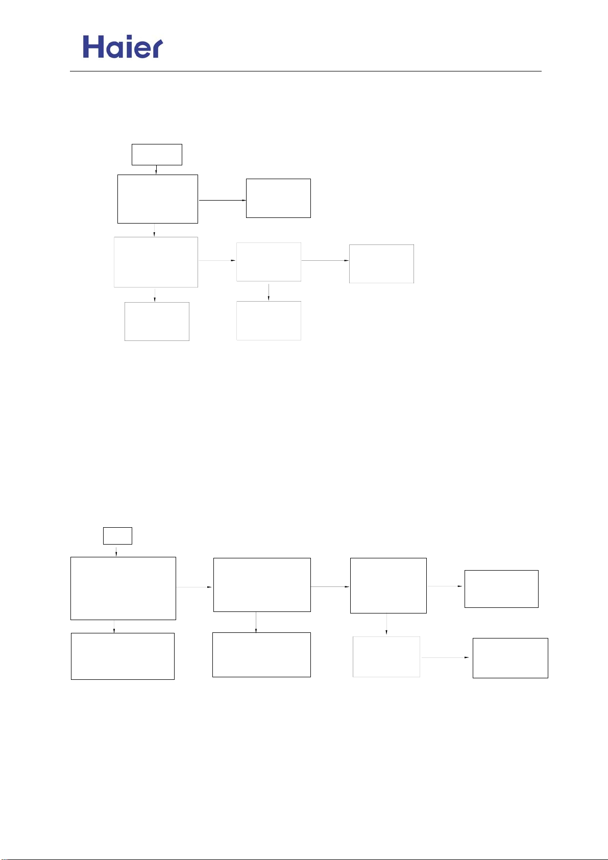
y,
y)
Commercial Air Conditioner Model: AU18/222XFERA
AS072/092/122XVERA
Trouble 7: Outdoor unit failure
Check the failure code on outdoor indicator board (5-lamp)
Trouble 8: Outdoor unit alarms sensor failure
Trouble 9: AC current over current protection or current transducer damaged, or compressor blocked rotor,
compressor great vibration, compressor abnormal startup, state detecting curcuit abnormal or compressor damaged.
The former twice failure can be resumed automatically, if outdoor board occurs this failure always, and can not be
resumed for a long time, that shows:
1. Power module (SPDU) damaged, please replace the power module, then re-wiring as per the wiring diagram (70%
possibility)
2. Short circuit in power board results in the power module damaged (15
3. Damaged compressor results in this failure (10
4. Main control board is fault
Trouble 10: High pressure failure
Reasons:
1. Over high system pressure results that the unit stop, and the compressor protection will work. The failure can be
resumed.
2. Pressure switch wire is not fixed well or in open circuit.
start
check if the connector
between pressure
switch and PCB is
fixed badly or damaged
replace pressure switch
connector, shut off and
be electrified again,
re-check
start
as per the wiring
diagram, check if
connection port
between sensor and
PCB is correct
yes
check if the sensor
is in open circuit or
the connection port
to PCB is in good
condition
yes
replace sensor
and check
again
yes
no
no
replace it (5% possibilit
check if the 2 straight
no
lugs on the pressure
switch are in good
condition
replace pressure
switch connector, shut
off and be electrified
again, re-check
re-fix the
sensor and
check again
check if the
sensor resistor
value is correct
yes
PCB is faulty
and repalce it,
check again
% possibility)
yes
no
replace sensor
and check
again
if outdoor fan
no
motor cannot
startup normally
in cooling mode
check if the
outdoor motor
has power input
% possibility)
yes
no
no
replace main
control board
and check again
replace outdoor
motor and check
again
-63-
Page 64
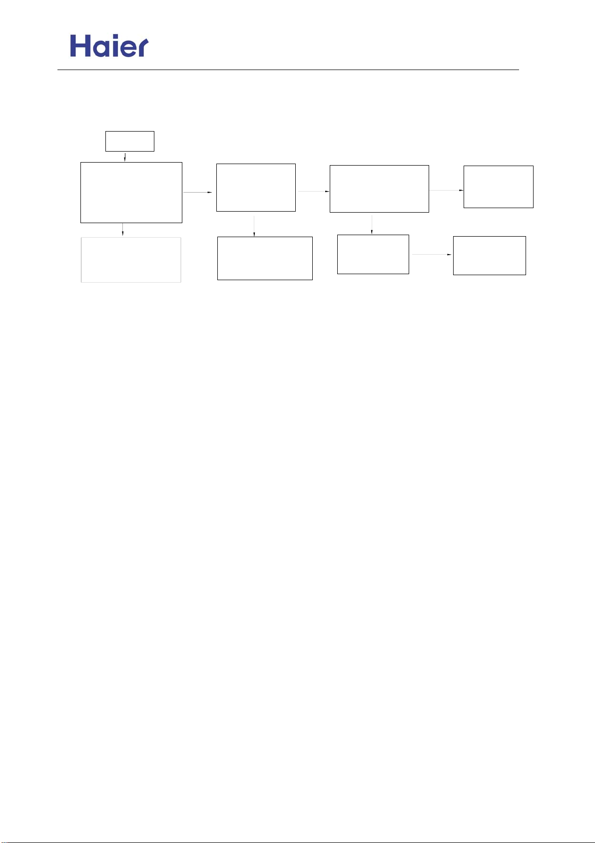
Commercial Air Conditioner Model: AU18/222XFERA
AS072/092/122XVERA
Failure 11: Low pressure switch failure
Reason: 1. Too low system pressure causes that the unit stops and the compressor protection works, the failure can be
resumed.
2. Pressure switch wire is not fixed well or in open circuit.
check if the connector
between pressure
switch and PCB is
fixed badly or damaged
(CN20 on PCB)
replace pressure switch
connector, shut off and
be electrified again,
re-check
start
yes
check if the 2
straight lugs on
no
the pressure
switch work badly
replace pressure
switch connector, shut
off and be electrified
again, re-check
yes
if indoor fan motor
cannot startup normally
no
in heating mode(except
for defrost)
check if the
indoor motor has
power input
yes
no
replace main
no
control board
and check again
replace indoor
motor and check
again
-64-
Page 65
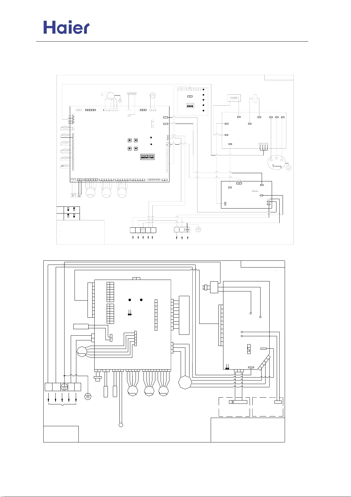
Commercial Air Conditioner Model: AU18/222XFERA
AS072/092/122XVERA
11. Electric data
11.1 Wiring diagram
W
1(L)
TO OUTDOOR
UNIT
B: BLACK BR: BROWN
R: RED W : WHITE
Y/G : YELLOW/GREEN
BL:BLUE Y:YELLOW
capacitor
CN2CN1
CN23
TO SPDU
TOCI
CN22
CN21
CN19
CONTROL
CIRCUIT
BOARD
CN18
PMV_A
TC
TS
TA
TD
TE
CN20
HP LP
M
ON
18000
BTU
SW5-6SW5-5
ON
22000
BTU
SW5-6SW5-5
TOCI P IPING TEMPERATURE SENSOR
TC CONDENSING TEMPERATURE SENSOR
TS: COMPRESSOR INHALE SENSOR
TA AMBIENT TEMPERATURE SENS OR
TD: COMPRESSOR VENT SENSOR
TE DEFROSTING TEMPERATURE SENSOR
OR : ORANGE
B : BLACK
Y/G : YELLOW/GREEN
R : RED
BL : BLUE
W : WHITE
CN14
PIPING
TEMPER-
ATURE
SENSOR
CN16
M
SWING
2(N)
MOTOR
B
R
BR
4
3
R
SW03
Y/G
Outdoor unit wiring diagram
AC FAN MOTOR
M
MLN
CN3
CN17
PMV_B
H
Y/G
PMV_C
CRANKCASE
HEATER
CN4
CN5
250VAC T3.15A
SW1 SW2
stop/downstart/up
SW4SW3
CN15CN16
PMV_D
4-WAY
VALVE
4WV
SV2
CN8
CN7
CN6
FUSE1
ON
LED2
LED1
SW5
DEBUG_LED
N
CN9
L
CN10
BUS
CN11
PTC
CN12
LED
87654321
CN13CN14
MM
Y/GBW
LN
C1
To Indoor Units
C2
BW
L
To Power Supply
Wall mounted unit wiring diagram
CN13
Y
SW01
W
SW02
CN17
BL
B
CN19
CN18
W W W W
PIPING
TEMPER-
ATURE
SENSOR
AMBIENT
TEMPERATURE
SENSOR
LED1
LED2
CN24
CN20
W
R
CN22
CN26
CN21
M M M
SWING
SWING
MOTOR
MOTOR
CN25
W
CN23
W
SWING
MOTOR
AC FAN MOTOR
ON
RR
N
LED
M
¡«
CN26
CN25
1234
SW5
RO
ACL
CN8
FUSE
T25A 250VAC
POWER
CIRCUIT
BOARD
capacitor
-+
BL OR
SPDU
220VAC-L
LED1
LED2
LED3
LED4
LED5
Y/G
reactor
ACN
RI
RL1
CN7
ION
GENERATOR
CN9
CN10
CN4
T3.15A
250VAC
R
CN11
FUSE1
CN1
220_L
CN8
CN5
W
ULTRAVIOLET
RADIATION
NOTE:
WHEN THE UNIT HAS NOT THE
FUNCTION OF HEALTH WITHOUT
THE PARTS IN THE DOTTED LINE.
0010576926
P(+)
N(-)
R
V
U
COMPRESSOR
CN2
CN1
CN5
CN4
CN3
220VAC-N
CN12
CN2
220_N
CN3
W
FRESH
CONTROLLER
WVU
W
B
W
-65-
Page 66
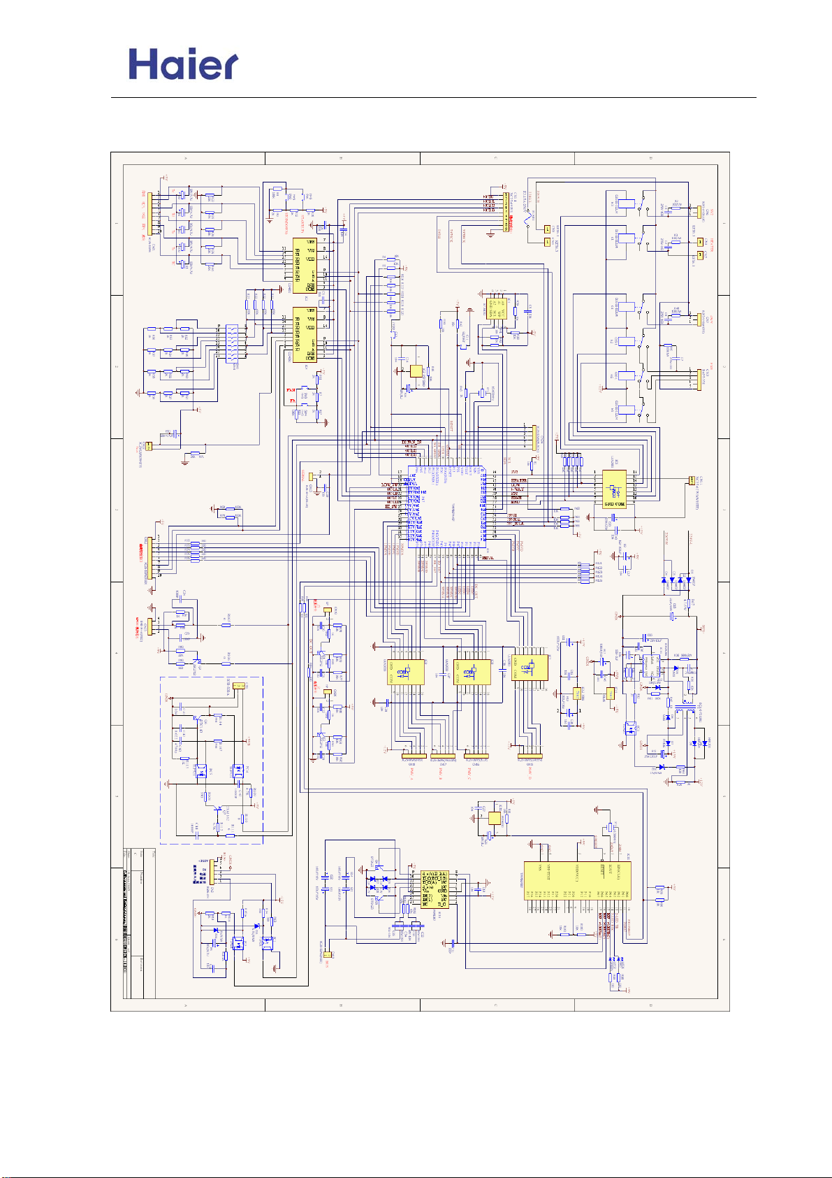
Commercial Air Conditioner Model: AU18/222XFERA
AS072/092/122XVERA
11.2 Circuit diagram
Outdoor circuit diagram:
-66-
Page 67
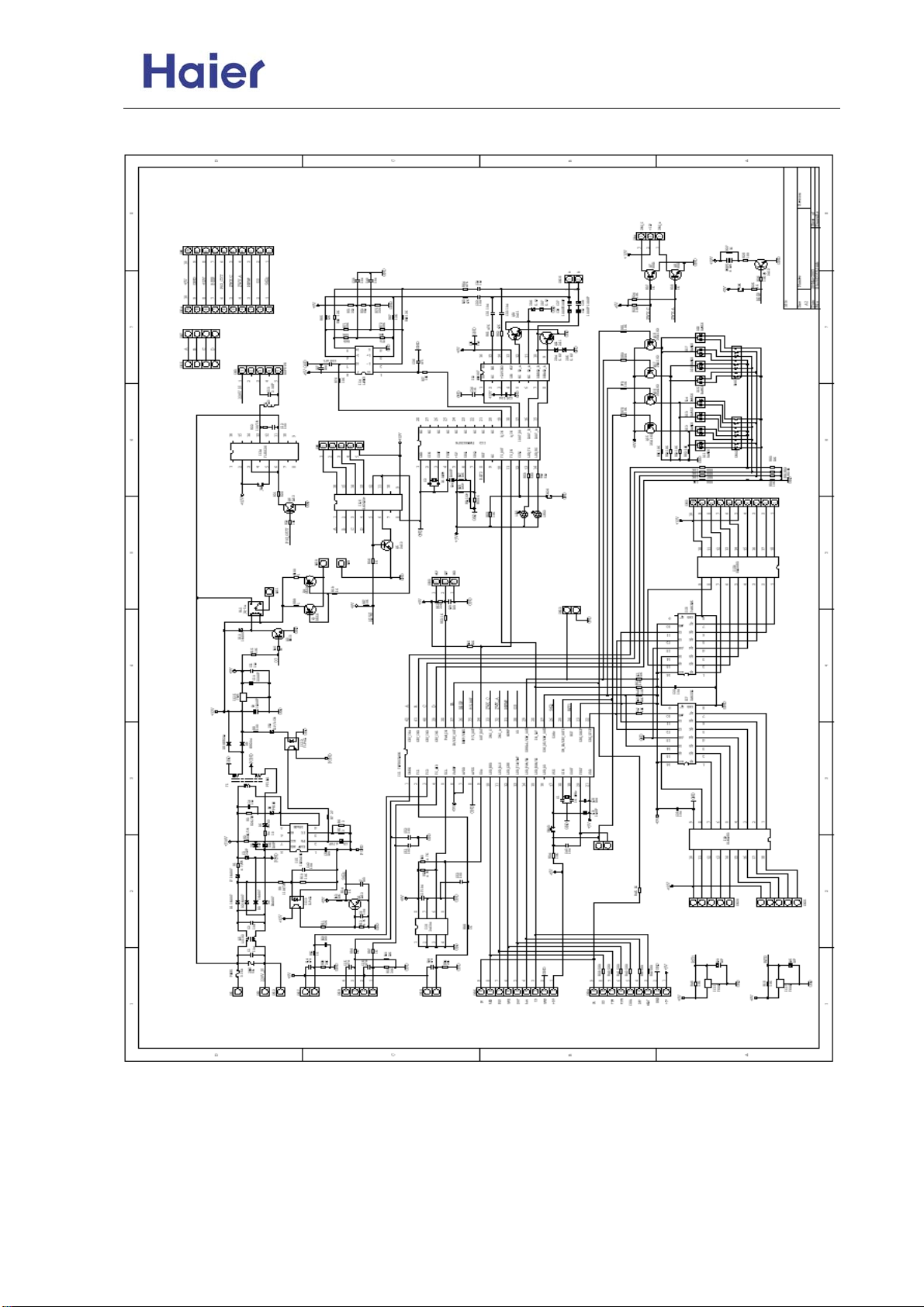
Commercial Air Conditioner Model: AU18/222XFERA
AS072/092/122XVERA
Indoor circuit diagram:
-67-
Page 68
Commercial Air Conditioner Model: AU18/222XFERA
AS072/092/122XVERA
11.3 Sensor part number and their resistor value
model name code sub-part code characteristic
AS072XVERA
AS092XVERA
AS122XVERA
AU182XFERA
AU222XFERA
suction temp. sensor 0010451513 001A3900059
coil temp. sensor 001A3900059
liquid pipe temp. sensor 001A3800103 001A3900004
discharging temp. sensor
mid-condensor temperature sensor
outdoor ambient temp. sensor
1.R25=10KΩ±3%
B25/50=3700K±3%
2.R25=23KΩ±2.5%
B25/50=4200K±3%
1.R25=10KΩ±3%
B25/50=3700K±3%
2.R25=23KΩ±2.5%
B25/50=4200K±4%
R25=10KΩ±3%
B25/50=3700K±3%
R80=50KΩ±3%
B25/80=4450K±3%
R25=10KΩ±3%
B25/50=3700K±3%
R25=10KΩ±3%
B25/50=3700K±3%
-68-
Page 69
Commercial Air Conditioner Model: AU18/222XFERA
AS072/092/122XVERA
R80=50KΩ±3%
B25/80=4450K±3%
T(℃)
-30 11600 24 536.6
-29 10860 25 511.1 -19 85.72 35 6.68
-28 10170 26 486.9 -18 80.96 36 5.43
-27 9529 27 464 -17 76.51 37 5.6
-26 8932 28 442.3 -16 72.33 38 5.59
-25 8375 29 421.7 -15 68.41 39 5.73
-24 7856 30 402.1 -14 64.73 40 5.52
-23 7372 31 383.6 -13 61.27 41 5.32
-22 6920 32 366 -12 58.02 42 5.12
-21 6498 33 349.3 -11 54.97 43 4.93
-20 6104 34 333.5 -10 52.1 44 4.9
-19 5736 35 318.4 -9 49.4 45 4.58
-18 5392 36 304.1 -8 46.86 46 4.42
-17 5071 37 290.5 -7 44.46 47 4.26
-16 4770 38 277.6 -6 42.21 48 4.11
-15 4488 39 265.3 -5 40.08 49 3.97
-14 4225 40 253.6 -4 38.08 50 3.83
-13 3978 41 242.5 -3 36.19 51 3.7
-12 3747 42 232 -2 34.41 52 3.57
-11 3531 43 221.9 -1 32.73 53 3.45
-10 3328 44 212.3 0 31.14 54 3.33
-9 3138 45 203.2 1 29.64 55 3.22
-8 2960 46 194.5 2 28.22 56 3.11
-7 2793 47 186.3 3 26.4 57 3.11
-6 2636 48 178.4 4 25.61 58 2.9
-5 2489 49 170.9 5 24.41 59 2.81
-4 2351 50 163.7 6 23.27 60 2.72
-3 2221 51 155.9 7 22.2 61 2.63
-2 2099 52 150.4 8 21.18 62 2.54
-1 1984 53 144.2 9 20.21 63 2.49
10 1092 20 12.36 74 1.73
11 1036 21 11.84 75 1.68
12 983.2 22 11.34 76 1.63
13 933.4 23 10.87 77 1.58
14 886.4 24 10.43 78 1.54
15 841.9 25 10 79 1.49
16 800 26 9.59 80 1.45
17 760.8 27 9.21
18 722.8 28 8.84
19 687.3 29 8.48
20 653.8 30 8.15
21 622 31 7.83
22 592 32 7.52
23 553.6 33 7.23
Rnom(KΩ)
0 1877 54 138.3 10 19.3 64 2.38
1 1775 55 132.7 11 18.43 65 2.3
2 1680 56 127.3 12 17.61 66 2.23
3 1590 57 122.1 13 16.83 67 2.16
4 1506 58 117.2 14 16.09 68 2.09
5 1426 59 112.5 15 15.38 69 2.03
6 1351 60 108 16 14.71 70 1.96
7 1280 61 103.8 17 14.08 71 1.9
8 1214 62 99.68 18 13.48 72 1.85
9 1151 19 12.9 73 1.79
R80=50KΩ±3%
B25/80=4450K±3%
T(℃)
Rnom(KΩ)
R25=10KΩ±3%
B25/50=3700K±3%
T(℃)
-20℃
Rnom(KΩ)
90.79 34 6.95
R25=10KΩ±3%
B25/50=3700K±3%
T(℃)
Rnom(KΩ)
-69-
Page 70
Commercial Air Conditioner Model: AU18/222XFERA
AS072/092/122XVERA
R25=23KΩ±2.5%
B25/50=4200K±3%
T(℃)
-20℃
-19℃
-18℃
-17℃
-16℃
-15℃
-14℃
-13℃
-12℃
-11℃
-10℃
-9℃
-8℃
-7℃
-6℃
-5℃
-4℃
-3℃
-2℃
-1℃
0℃
1℃
2℃
3℃
4℃
5℃
6℃
7℃
8℃
9℃
10℃
11℃
12℃
13℃
14℃
15℃
16℃
17℃
18℃
19℃
20℃
21℃
Rnom(KΩ)
281.34
263.56
247.04
231.66
217.35
204.02
191.61
180.04
169.24
159.17
149.77
140.99
132.78
125.11
117.93
111.22
104.93
99.04
93.52
88.35
83.5
78.94
74.67
70.65
66.88
63.33
60
56.86
53.91
51.13
48.51
46.04
43.72
41.52
39.45
37.5
35.66
33.92
32.27
30.72
29.25
27.86
R25=23KΩ±2.5%
B25/50=4200K±3%
T(℃)
22℃
23℃
24℃
25℃
26℃
27℃
28℃
29℃
30℃
31℃
32℃
33℃
34℃
35℃
36℃
37℃
38℃
39℃
40℃
41℃
42℃
43℃
44℃
45℃
46℃
47℃
48℃
49℃
50℃
51℃
52℃
53℃
54℃
55℃
56℃
57℃
58℃
59℃
60℃
Rnom(KΩ)
26.54
25.3
24.12
21.94
20.94
19.99
19.09
18.23
17.42
16.65
15.92
15.22
14.56
13.93
13.34
12.77
12.23
11.71
11.22
10.76
10.31
9.89
9.49
8.74
8.39
8.05
7.73
7.43
7.14
6.86
6.34
5.87
5.65
5.44
5.24
23
9.1
6.6
6.1
-70-
Page 71
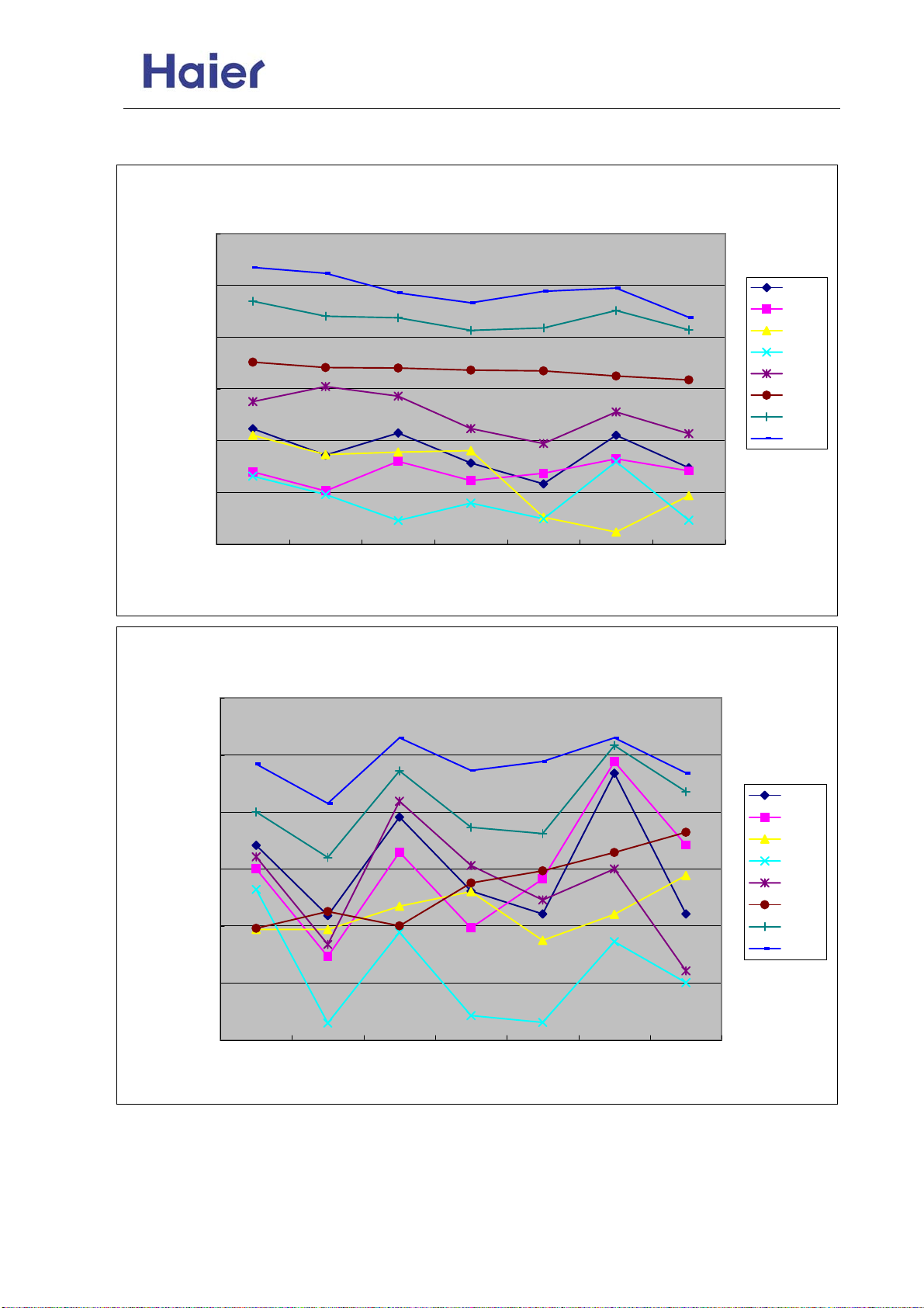
Commercial Air Conditioner Model: AU18/222XFERA
AS072/092/122XVERA
12. Performance curves
The data in the curves are measured with three indoor unit AS07+AS09+AS12 and AU182.
10000
9000
8000
7000
6000
Heating capacity (W)
5000
4000
2900
2700
2500
2300
Power input (W)
2100
1900
1700
16/10 18/12 20/14.5 21/15 22/16 24/17 26/18
16/10 18/12 20/14.5 21/15 22/16 24/17 26/18
Heating capacity curves
-6/-7
-4/-5
-1/-2
1/0
6/5
7/6
12/10
16/15
indoor WB/DB
Power input curves in heating mode
-6/-7
-4/-5
-1/-2
1/0
6/5
7/6
12/10
16/15
indoor WB/DB
-71-
Page 72
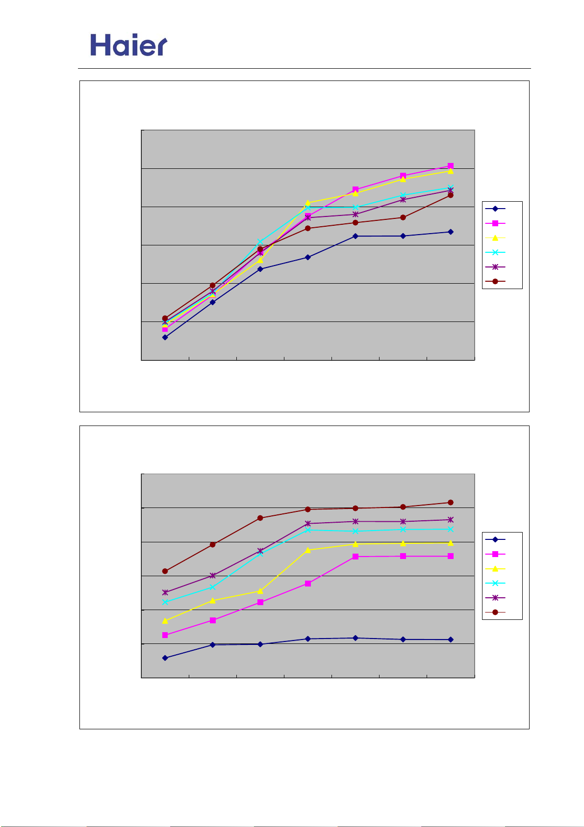
Commercial Air Conditioner Model: AU18/222XFERA
AS072/092/122XVERA
Cooling capacity curves
8000
7000
6000
5000
4000
Cooling capacity (W)
3000
2000
18/12 20/14 22/16 25/18 27/19 30/22 32/24
3000
-5
20
25
32
35
40
indoor DB/WB
Power input curves in cooling mode
2500
2000
1500
Power input (W)
1000
500
0
18/12 20/14 22/16 25/18 27/19 30/22 32/24
-5
20
25
32
35
40
indoor DB/WB
-72-
Page 73
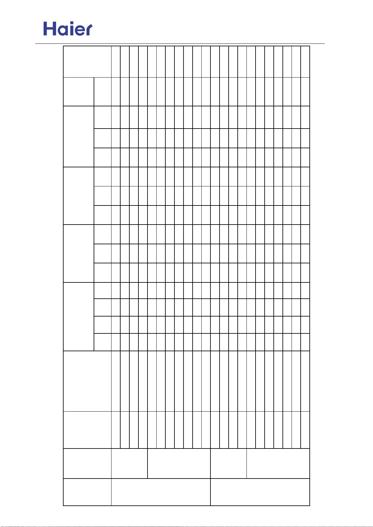
Commercial Air Conditioner Model: AU18/222XFERA
AS072/092/122XVERA
LABEL
ENERGY
EER
total current
total power input
total cooling
rated
(W/W)
(A)@230V
(kW)
capacity(kW)
capacity
Data
max.
data
rated
min.
data
Data
max.
data
rated
min.
data
data
max.
data
rated
min.
data
D
Unit
C
Unit
B
Output/kW
Rated capacity
Unit
(Nom. cooling)
Application
Compatible
Comb.
A
Unit
indoor units
07+12 cooling and heating 2.0 3.2 — — 1.00 5.20 5.80 0.47 1.75 2.30 2.15 7.80 10.20 2.97 C
09+09 cooling and heating 2.5 2.5 — — 1.00 5.00 5.40 0.47 1.75 2.30 2.15 7.80 10.20 2.86 C
09+12 cooling and heating 2.3 2.9 — — 1.00 5.20 5.80 0.47 1.75 2.30 2.15 7.80 10.20 2.97 C
BI (1x2)
12+12 cooling and heating 2.6 2.6 — — 1.00 5.20 5.80 0.47 1.75 2.30 2.15 7.80 10.20 2.97 C
07+07+07 cooling and heating 1.73 1.73 1.73 — 1.50 5.20 5.80 0.50 1.70 2.30 2.29 7.62 10.20 3.06 B
07+07+09 mainly cooling 1.60 1.60 2.00 — 1.50 5.20 5.80 0.50 1.70 2.30 2.29 7.62 10.20 3.06 B
07+07+12 mainly cooling 1.39 1.39 2.42 — 1.50 5.20 5.80 0.50 1.70 2.30 2.29 7.62 10.20 3.06 B
07+09+09 mainly cooling 1.48 1.86 1.86 — 1.50 5.20 5.80 0.50 1.70 2.30 2.29 7.62 10.20 3.06 B
07+09+12 mainly cooling 1.30 1.63 2.27 — 1.50 5.20 5.80 0.50 1.65 2.30 2.29 7.62 10.20 3.15 B
09+09+09 mainly cooling 1.73 1.73 1.73 — 1.50 5.20 5.80 0.50 1.65 2.30 2.29 7.62 10.20 3.15 B
09+09+12 mainly cooling 1.56 1.56 2.18 — 1.50 5.30 5.80 0.50 1.65 2.30 2.29 7.40 10.20 3.21 A
07+14 cooling and heating 2.0 4.1 — — 1.00 6.10 6.50 0.47 2.20 2.90 2.20 9.76 12.90 2.77 D
09+12 cooling and heating 2.5 3.2 — — 1.00 5.70 6.20 0.47 2.00 2.90 2.20 8.87 12.90 2.85 C
09+14 cooling and heating 2.4 4.0 — — 1.00 6.40 6.50 0.47 2.20 2.90 2.20 9.76 12.90 2.91 C
12+12 cooling and heating 3.2 3.2 — — 1.00 6.40 6.50 0.47 2.20 2.90 2.20 9.76 12.90 2.91 C
07+07+09 cooling and heating 2.0 2.0 2.4 — 1.50 6.40 6.50 0.50 2.15 2.90 2.30 9.54 12.90 2.98 C
07+07+12 mainly cooling 1.78 1.78 2.84 — 1.50 6.40 6.50 0.50 2.15 2.90 2.30 9.54 12.90 2.98 C
07+09+09 mainly cooling 1.70 2.35 2.35 — 1.50 6.40 6.50 0.50 2.15 2.90 2.30 9.54 12.90 2.98 C
07+09+12 mainly cooling 1.66 2.07 2.66 — 1.50 6.40 6.50 0.50 2.15 2.90 2.30 9.54 12.90 2.98 C
09+09+09 mainly cooling 2.13 2.13 2.13 — 1.50 6.40 6.50 0.50 2.15 2.90 2.30 9.54 12.90 2.98 C
09+09+12 mainly cooling 1.95 1.95 2.50 — 1.50 6.40 6.50 0.50 2.15 2.90 2.30 9.54 12.90 2.98 C
09+12+12 mainly cooling 1.80 2.3 2.3 — 1.50 6.40 6.50 0.50 2.05 2.90 2.30 9.32 12.90 3.12 B
TRI (1x3)
BI (1x2)
TRI (1x3)
unit
Outdoor
AU182
XFERA
-73-
AU222
XFERA
Page 74
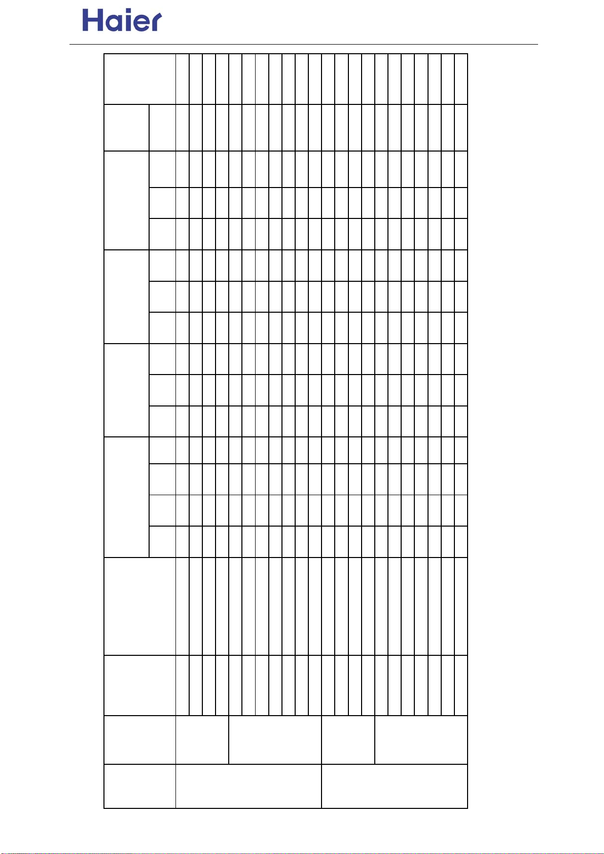
Commercial Air Conditioner Model: AU18/222XFERA
AS072/092/122XVERA
LABEL
ENERGY
EER
total current
total power input
total heating
rated
(W/W)
(A)@230V
(W)
capacity(KW)
capacity
Data
max.
data
rated
min.
data
Data
max.
data
rated
min.
data
data
max.
data
rated
min.
data
D
Unit
C
Unit
B
Unit
Output/kW
Rated capacity
(Nom. heating)
A
Unit
Application
Compatible
indoor units
07+12 cooling and heating 2.30 3.80 — — 1.20 6.10 6.50 0.55 1.90 2.30 2.50 8.43 10.20 3.21 C
09+09 cooling and heating 2.90 2.90 — — 1.20 5.80 6.50 0.55 1.90 2.30 2.50 8.43 10.20 3.05 C
09+12 cooling and heating 2.80 3.80 — — 1.20 6.60 6.80 0.55 1.90 2.30 2.50 8.43 10.20 3.47 B
12+12 cooling and heating 3.30 3.30 — — 1.20 6.60 7.00 0.55 1.90 2.30 2.50 8.43 10.20 3.47 B
07+07+07 cooling and heating 2.20 2.20 2.20 — 1.50 6.60 7.00 0.55 1.85 2.30 2.50 8.21 10.20 3.57 B
07+07+09 mainly cooling 2.05 2.05 2.55 — 1.50 6.65 7.00 0.55 1.85 2.30 2.50 8.21 10.20 3.59 B
07+07+12 mainly cooling 1.85 1.85 2.95 — 1.50 6.65 7.00 0.55 1.85 2.30 2.50 8.21 10.20 3.59 B
07+09+09 mainly cooling 1.85 2.40 2.40 — 1.50 6.65 7.00 0.55 1.85 2.30 2.50 8.21 10.20 3.59 B
07+09+12 mainly cooling 1.70 2.15 2.80 — 1.50 6.65 7.00 0.55 1.85 2.30 2.50 8.21 10.20 3.59 B
09+09+09 mainly cooling 2.20 2.20 2.20 — 1.50 6.60 7.00 0.55 1.85 2.30 2.50 8.21 10.20 3.57 B
09+09+12 mainly cooling 2.05 2.05 2.55 — 1.50 6.65 7.00 0.55 1.80 2.30 2.50 7.99 10.20 3.69 A
07+14 cooling and heating 2.30 4.60 — — 1.20 6.90 7.20 0.55 2.20 2.90 2.50 9.76 12.90 3.14 C
09+12 cooling and heating 2.90 3.80 — — 1.20 6.70 7.20 0.55 2.20 2.90 2.50 9.76 12.90 3.05 C
09+14 cooling and heating 2.75 4.45 — — 1.20 7.20 7.20 0.55 2.20 2.90 2.50 9.76 12.90 3.27 C
12+12 cooling and heating 3.60 3.60 — — 1.20 7.20 7.20 0.55 2.20 2.90 2.50 9.76 12.90 3.27 C
07+07+09 cooling and heating 2.20 2.20 2.80 — 1.50 7.20 7.40 0.55 2.15 2.90 2.50 9.54 12.90 3.35 C
07+07+12 mainly cooling 2.00 2.00 3.20 — 1.50 7.20 7.40 0.55 2.15 2.90 2.50 9.54 12.90 3.35 C
07+09+09 mainly cooling 2.10 2.55 2.55 — 1.50 7.20 7.40 0.55 2.10 2.90 2.50 9.32 12.90 3.43 B
07+09+12 mainly cooling 1.85 2.30 3.05 — 1.50 7.20 7.40 0.55 2.10 2.90 2.50 9.32 12.90 3.43 B
09+09+09 mainly cooling 2.40 2.40 2.40 — 1.50 7.20 7.40 0.55 2.10 2.90 2.50 9.32 12.90 3.43 B
09+09+12 mainly cooling 2.18 2.18 2.84 — 1.50 7.20 7.40 0.55 2.05 2.90 2.50 9.09 12.90 3.51 B
09+12+12 mainly cooling 2.00 2.60 2.60 — 1.50 7.20 7.40 0.55 2.05 2.90 2.50 9.09 12.90 3.51 B
Comb.
unit
Outdoor
BI (1x2)
AU182
XFERA
TRI (1x3)
-74-
BI (1x2)
AU222
XFERA
TRI (1x3)
Page 75
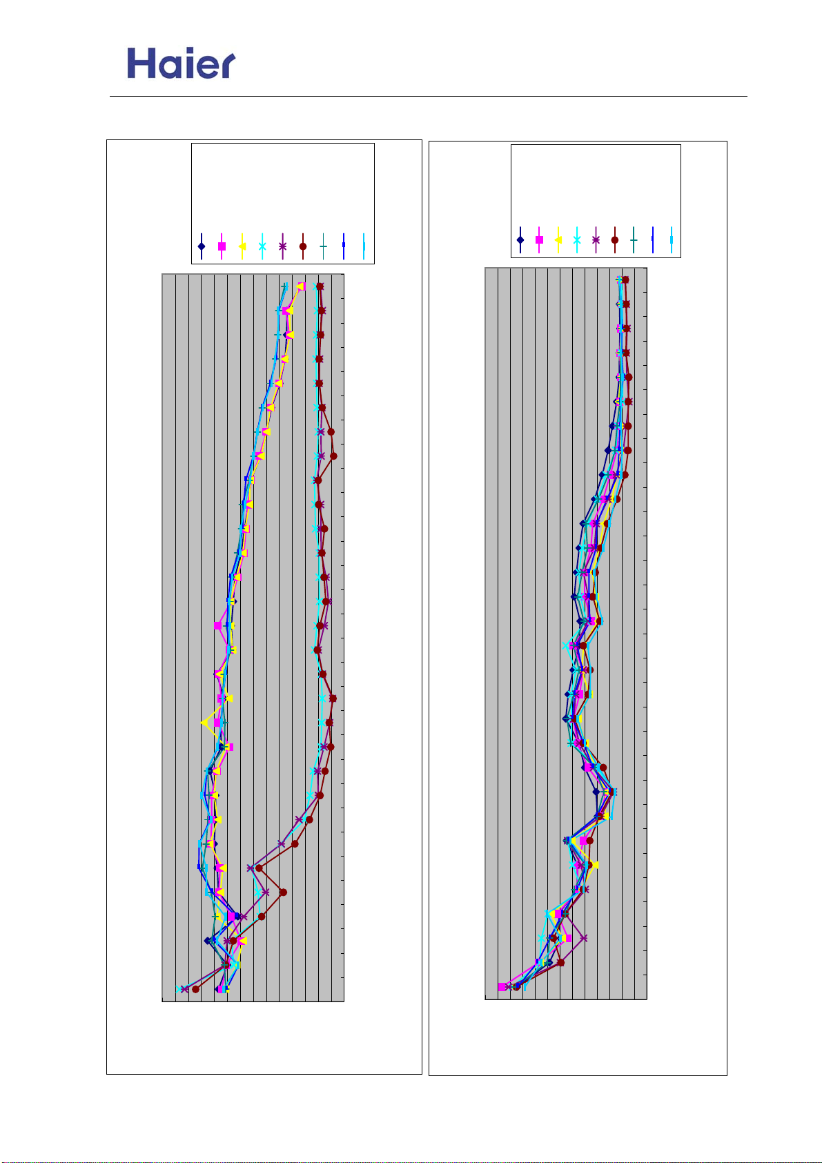
AS072/092/122XVERA
Commercial Air Conditioner Model: AU18/222XFERA
13. Noise level
cooling high
cooling med
cooling low
fan high
fan med
fan low
heating high
heating med
heating low
cooling high
cooling med
cooling low
fan high
fan med
fan low
heating high
heating med
heating low
1/3 octave band noise level-AU182XFERA
.0
00
00
2
.0
00
60
1
.0
00
25
1
.0
00
00
1
0
0.
00
8
0
0.
30
6
0
0.
00
5
0
0.
00
4
0
0.
15
3
0
0.
50
2
0
0.
00
2
0
0.
60
1
0
0.
25
1
0
0.
00
1
.0
00
8
.0
30
6
.0
00
5
.0
00
4
.0
15
third octave band frequency Hz
3
.0
50
2
.0
00
2
.0
60
1
.0
25
1
.0
00
1
0
0.
8
0
3.
6
0
0.
5
0
0.
4
5
1.
3
0
5.
2
1/3 octave band noise level-AS072XVERA
.0
00
00
2
.0
00
60
1
.0
00
25
1
.0
00
00
1
0.0
00
8
0.0
30
6
0.0
00
5
0.0
00
4
0.0
15
3
0.0
50
2
0.0
00
2
0.0
60
1
0.0
25
1
0.0
00
1
.0
00
8
.0
30
6
.0
00
5
.0
00
4
.0
15
third octave band frequency Hz
3
.0
50
2
.0
00
2
.0
60
1
.0
25
1
.0
00
1
0.0
8
3.0
6
0.0
5
0.0
4
1.5
3
5.0
2
0.0
70.0
sound pressure level DB
65.0
60.0
50.0
55.0
45.0
40.0
30.0
35.0
20.0
25.0
5.0
10.0
15.0
20.0
25.0
30.0
35.0
40.0
45.0
50.0
55.0
60.0
65.0
0.0
5.0
10.0
15.0
Sound pressure level DB
-75-
Page 76
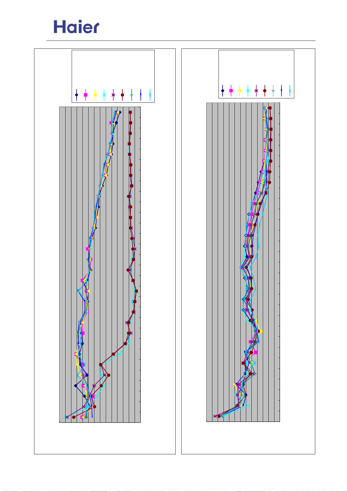
Commercial Air Conditioner Model: AU18/222XFERA
AS072/092/122XVERA
cooling high
cooling med
cooling low
fan high
fan med
fan low
heating high
heating med
cooling high
cooling med
cooling low
fan high
fan med
fan low
heating high
heating med
heating low
heating low
1/3 octave band noise level-AU182XFERA
10.0
15.0
20.0
25.0
30.0
35.0
40.0
45.0
50.0
55.0
60.0
65.0
70.0
.0
00
00
2
.0
00
60
1
.0
00
25
1
.0
00
00
1
0
0.
00
8
0
0.
30
6
0
0.
00
5
0
0.
00
4
0
0.
15
3
0
0.
50
2
0
0.
00
2
0
0.
60
1
0
0.
25
1
0
0.
00
1
.0
00
8
.0
30
6
.0
00
5
.0
00
4
.0
15
3
.0
50
2
.0
00
2
.0
60
1
.0
25
1
.0
00
1
0
0.
8
0
3.
6
0
0.
5
0
0.
4
5
1.
3
0
5.
2
0.0
5.0
sound pressure level DB
third octave band frequency Hz
1/3 octave band noise level-AS092XVERA
30.0
35.0
40.0
45.0
50.0
55.0
60.0
65.0
20.0
25.0
10.0
15.0
.0
00
00
2
.0
00
60
1
.0
00
25
1
.0
00
00
1
0
0.
00
8
0
0.
30
6
0
0.
00
5
0
0.
00
4
0
0.
15
3
0
0.
50
2
0
0.
00
2
0
0.
60
1
0
0.
25
1
0
0.
00
1
.0
00
8
.0
30
6
.0
00
5
.0
00
4
.0
15
3
.0
50
2
.0
00
2
.0
60
1
.0
25
1
.0
00
1
0
0.
8
0
3.
6
0
0.
5
0
0.
4
5
1.
3
0
5.
2
0.0
5.0
Sound pressure level DB
third octave band frequency Hz
-76-
Page 77
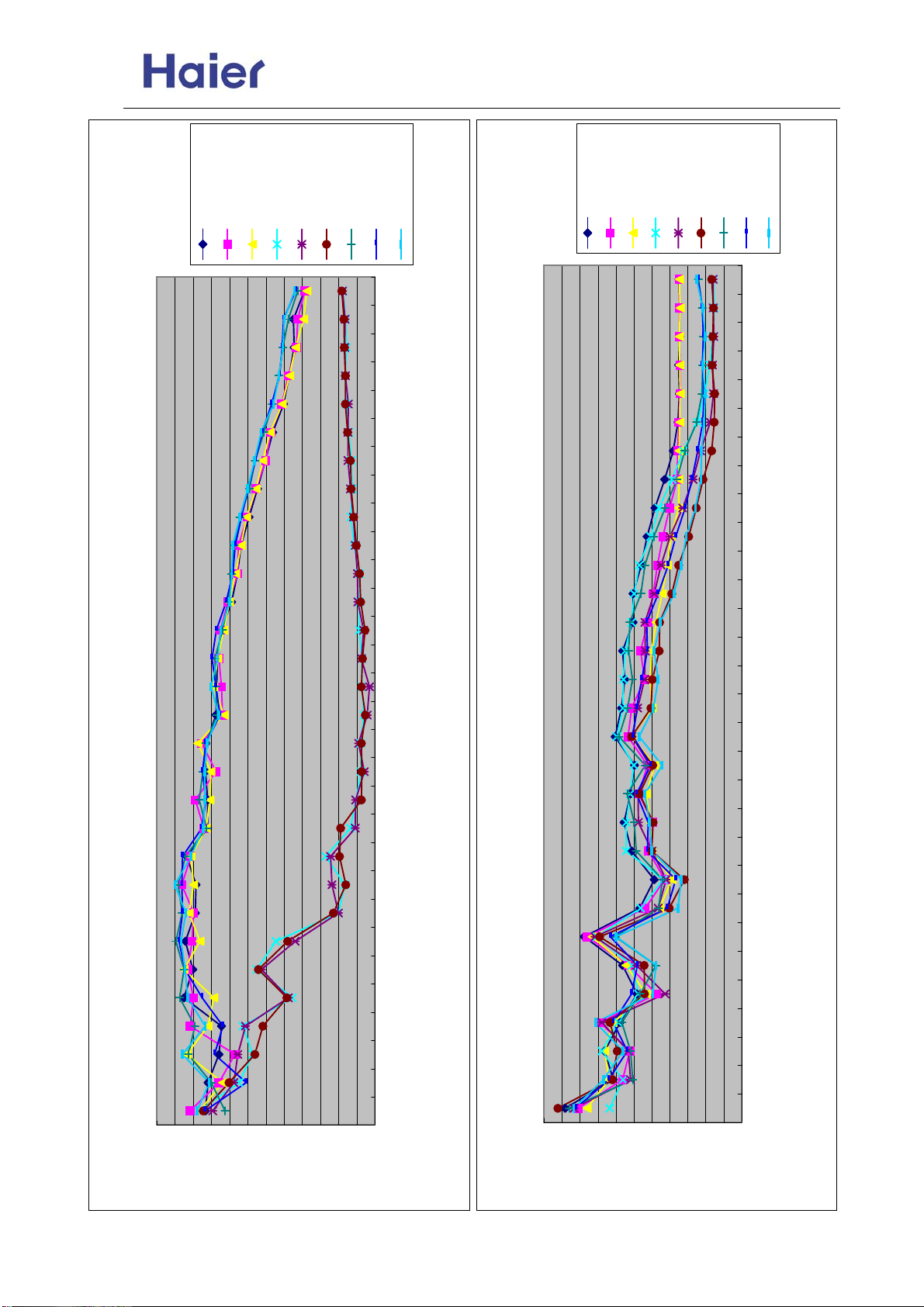
Commercial Air Conditioner Model: AU18/222XFERA
AS072/092/122XVERA
cooling high
cooling med
cooling low
fan high
fan med
fan low
heating high
heating med
cooling high
cooling med
cooling low
fan high
fan med
fan low
heating high
heating med
heating low
heating low
1/3 octave band noise level-AU182XFERA
.0
00
00
2
.0
00
60
1
.0
00
25
1
.0
00
00
1
0
0.
00
8
0
0.
30
6
0
0.
00
5
0
0.
00
4
0
0.
15
3
0
0.
50
2
0
0.
00
2
0
0.
60
1
0
0.
25
1
0
0.
00
1
.0
00
8
.0
30
6
.0
00
5
.0
00
4
.0
15
3
.0
50
2
.0
00
2
.0
60
1
.0
25
1
.0
00
1
0
0.
8
0
3.
6
0
0.
5
0
0.
4
5
1.
3
0
5.
2
third octave band frequency Hz
1/3 octave band noise level-AS122XVERA
.0
00
00
2
.0
00
60
1
.0
00
25
1
.0
00
00
1
0
0.
00
8
0
0.
30
6
0
0.
00
5
0
0.
00
4
0
0.
15
3
0
0.
50
2
0
0.
00
2
0
0.
60
1
0
0.
25
1
0
0.
00
1
.0
00
8
.0
30
6
.0
00
5
.0
00
4
.0
15
3
.0
50
2
.0
00
2
.0
60
1
.0
25
1
.0
00
1
0
0.
8
0
3.
6
0
0.
5
0
0.
4
5
1.
3
0
5.
2
0.0
0.0
sound pressure level DB
5.0
10.0
15.0
20.0
25.0
30.0
35.0
40.0
45.0
50.0
55.0
60.0
55.0
50.0
45.0
40.0
35.0
30.0
25.0
20.0
5.0
10.0
15.0
Sound pressure level DB
third octave band frequency Hz
-77-
Page 78
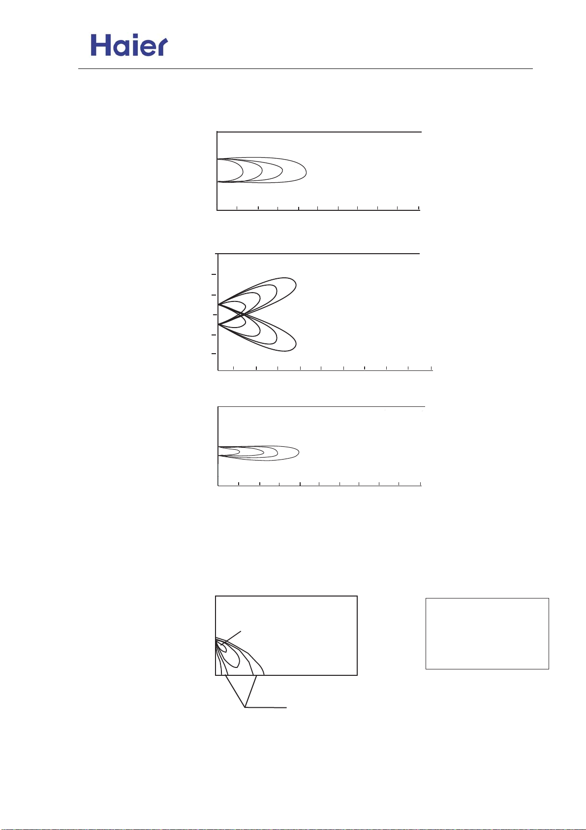
AS072/092/122XVERA
14. Air velocity and distribution
Fig 1
top view
flow control panel horizal
lourer:center
Fig 2
top view
flow control panel horizontal
lourer:right and left
Fig 3
top view
flow control panel horizontal
lourer:center
Fig 4
top view
flow control panel vertical
lourer:center
Commercial Air Conditioner Model: AU18/222XFERA
87
87
unit m/s
10
9
unit m/s
unit m/s
10
9
m
m
10987654321
m
m
m
m
3
2
1
0
1
m
2
1
0
1
2
2
3
3
1.8
1
3.0
1.0
2.0
1
2.0
0
2.0
0
0.5
0.25
2
0.5
1.0
1.0
0.5
0.5
1.0
1
2
43
0.25
0.25
0.25
43
65
65
unit
m/s
Condition
1.8
2.0
Fan speed:high
Operation mode:fan
Voltage:230V,50Hz
1.0
0.5
1
0
2
3
0.25
5 6
4
m
-78-
Page 79
Commercial Air Conditioner Model: AU182XFERA
AS072/092/122XVERA
Sincere Forever
Haier Group
Haier Industrial Park, No.1, Haier Road
266101, Qingdao, China
http://www.haier.com
 Loading...