

Haier AU282XHBAA Schematic

SERVICE MANUAL
Commercial Air Conditioning
3HP fixed frequency free multi
AU282XHBAA
AF072XCBAA AS072XCBAA AE072XCBAA AB072XCBAA
AF092XCBAA AS092XCBAA AE092XCBAA AB092XCBAA
AF122XCBAA AS122XCBAA AE122XCBAA AB122XCBAA
AF142XCBAA AS142XCBAA AE142XCBAA AB142XCBAA
●
Features
●Auto-check function
●Auto –restart function (optional )
●Group control function
●Room card function for ceiling concealed type
●Weekly timer (optional)
●Variable Control modes
●The total capacity of indoor unit can be more than that of outdoor unit.
●With new environment friendly refrigerant R407C
HAIER GROUP
MANUAL CODE: SYJS-023-03 REV: 2 EDITION: 2005.03

CONTENTS
CONTENTS
Contents
1. Description of products & features
2. Specification
3. Safety precaution
4. Net dimension of indoor and outdoor
5. Installation instructions
6. Parts and functions
7. Remote controller functions
8. Refrigerant diagram
9. Electrical control functions
10. Diagnostic information (trouble shooting)
11. Electrical data
12. Exploded view and parts lists
13. Performance curves
14. Noise level charts
15. Air velocity distribution

1.DESCRIPTION OF PRODUCTS & FEATURES
1.1. Products code explanation
A U 28 2 X H B A A
Climate type: T1 (see table 1)
Design number (A stands for design sequence,fixed frequency type)
Product type: A stands for heat pump type, refrigerant is R22
B stands for heat pump type, refrigerant is R407C
M stands for cool only type, refrigerant is R22
N stands for cool only type, refrigerant is R407C
Appearance character
Product series: X stands for 1 to 2, 1 to 3, 1 to 4
Applicable voltage: 2 stands for 220-240V/50Hz,
4 stands for 220V/60Hz,N stand for 380V/50Hz
Cooling / Heating capacity,28=28000BTU/h
Product type : “B” stands for cassette type, “C” stands for convertible
type, ”D” stands for duct, “S” stands for split type, ”Q” stands for chiller
system, "E" stands for ceiling concealed type, “U” stands for outdoor
unit
Air Conditioner
1.2 Brief Introduction for T1、T2、T3 working condition
Climate type
Type of Air
Conditioner
Cooling Only
Heat pump
Electricity Heating
T1 T2 T3
18 ℃~43℃ 10℃~35℃ 21℃~52℃
-7℃~43℃ -7℃~35℃ -7℃~52℃
~43℃ ~35℃ ~52℃
1.3 Operating Range of Air Conditioners
Temp. Mode Rated Maximum Minimum
Cooling
Heating
Indoor
Outdoor
Indoor
Outdoor
DB ℃
WB ℃
DB ℃
WB ℃
DB ℃
WB ℃
DB ℃
WB ℃
27 32 18
19 23 14
35 43 10
24 26 6
20 27 15
14.5 --- --
7 24 -7
6 18 ---

1.4 Product character
1.4.1 Operating individually and operating simultaneously
The unit can realize individual operation which can control one unit running, stop, and adjusting running
mode. Also the unit can operate simultaneously which control multi indoor units at the same time.
1.4.2 Variable quantity of indoor unitIf you want to add or reduce the quantity of indoor units (of course
the match must correspond with the design), it can meet your need at any time. More convenient, more
random.
1.4.3 Universal outdoor unit, multiform indoor unit
We realize universal outdoor unit, and 6 kinds of indoor unit, choose freely according to customer’s favor
and indoor decoration, more stylish and more beautiful
1.4.4 The total capacity of indoor unit can be more than that of outdoor unit.
When all the indoor units are running at the same time, the actual capacity of every indoor unit is
proportional according to outdoor capacity.
1.4.5 Long distribution pipe and high drop
The unit can realize long distribution pipe and high drop, the detailed information please refer to the
specification, consequently, the installation can be more free, and can meet various need of the
customer.
1.4.6 Ceiling concealed type unit be equipped with high efficiency filter, and its high static pressure
can be up to 30Pa, running more silent, making room air more comfortable and more clean.
1.4.7 The ceiling concealed type can realize the “Room Card” function, and take it convenient for
hotel management.
1.4.8 Auto-check function
The unit can display the malfunction codes on the control board by using advanced auto-check
technology ,convenient for user find and dwell with the abnormal running.
1.4.9 Auto –restart function (optional );
All indoor units have auto-restart function. When the power supply cut off suddenly, the unit will
automatically recover the previous running mode once the power supply is on.
1.4.10 Group control function
1.4.11 Weekly timer (optional)
1.4.12 Variable Control modes
Wired remote control ;
Remote control;
*Group control: a. With remote monitor function; b. Auto changeover function

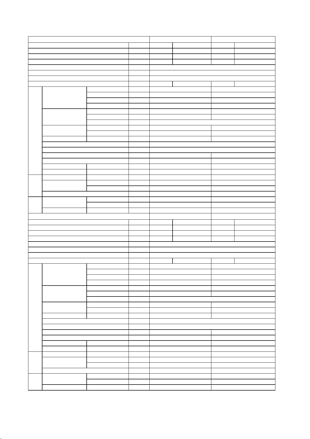
2. SPECIFICATIONS
Item Model AU282XHBAA
Function
Capacity
Capacity
Total power input
Max. power input
EER or COP
Dehumidifying capacity
Power cable
Communication cable
Power source
Running / Max.Running current
Start current (system A / system B)
Fuse size (recommended size)
Compressor
Fan
Heat exchanger
Dimension
(L×W×H)
Drainage pipe material, diameter mm
Refrigerant control method
Defrosting method
Type of 4-way valve
Material of reduce noise
Crankcase heater power
Noise level H/M/L dB(A)
Weight Net / Shipping kg / kg
Refrigerant
Pipe
Connecting method
Piping
Between I.D &O.D
Model / Manufacture ——
Oil charge and type ——
Type ——
Number ——
Type × Number ——
Speed r/min
Motor output power W
Air-flows (H/M/L) m³/h
Type / Diameter mm
Total area m²
Temp. scope
External mm
Package mm
Type / Charge g
No need to recharge m
Recharge g/m
Liquid mm
Gas mm
Drop between IU & OU
Drop between indoor units
Piping length
Total length
——
BTU/h
W
W
W
W/W
10‐³×m³/h
——
——
N, V, Hz
A / A 15.0/17.0 14.0/16.0
A
A
℃
——
——
——
——
W
——
m
m
m
m
Cooling Heating
28000 32000
8200 9300
3400 3400
3900 3900
2.40 2.80
//
3 × 3.0mm
2
8x(0.75~1.25mm
1, 220~230, 50
35.0 / 35.0
30
PG260X2CS-4KT1 / TOSHIBA
720 CC (RB68AF/T68/α68TF)
Rotary (Fix speed)
2
Axial × 1
50 / 840+50 / 590+50
1000+
60
4000/3000/2000
TP2M / 9.52x0.35
0.77
cooling: 43~60 / heating: 6~7
948x340x830
1050x440x979
/
Capillary tube
Automatic
DPF-6
XPE
/
58/-/-
74/89
R407C / 1900 × 2
Piping length less than 5 meters in one system
35
Φ6.35
Φ12.7
Flared
≤5 (per way)
≤5 (per way)
≤10 (per way)
≤20 (2 ways)
2
)
* Long piping length and large drop between the indoor and outdoor unit (which exceeds standard value) will obviously reduce the capacity.

Item Model AS072XCBAA AS092XCBAA
Function
Capacity
Capacity
Dehumidifying capacity
Power cable
Communication cable
Power source
Running current
Fan
Heat exchanger
Dimension
(L×W×H)
Drainage pipe material, diameter mm
Controller type
Refrigerant control Capillary tube
Fresh air hole dimension /
Electricity Heater
Noise level H/M/L dB(A)
Weight Net / Shipping kg / kg
Refrigerant
Pipe
Piping
Connecting method
Type × Number ——
Speed r/min
Motor output power W
Air-flows (H/M/L) m³/h
Type / Diameter mm
Total area m²
Temp. scope
External mm
Package mm
Type ——
Liquid mm
Gas mm
——
BTU/h
W
10‐³×m³/h
——
——
N, V, Hz
A / A 0.10 0.10 0.10 0.10
℃
——
——
mm
——
——
Cooling Heating Cooling Heating
7000 8000 9000 10000
2000 2300 2600 2900
1.0 / 1.0 /
3 × (1.0~1.5mm2 )
2x(0.75~1.25mm2 )
1, 220~230, 50
CROSS×1 CROSS×1
900/800/700 900/800/700
25 25
400/350/300
400/350/300
TP2M / 6.35×0.7
about 0.15 about 0.15
cooling: 6~7 / heating: 43~60
795×197×265 795×197×265
863×304×330 863×304×330
PVC, 11.4/16.4
Phone type infrared
/
37/35/30 37/35/30
7.6/10.6 7.6/10.6
R407C
6.35
12.7
Flared
Item Model AS122XCBAA AS142XCBAA
Function
Capacity
Capacity
Dehumidifying capacity
Power cable
Communication cable
Power source
Running current
Fan
Heat exchanger
Dimension
(L×W×H)
Drainage pipe material, diameter mm
Controller type
Refrigerant control Capillary tube
Fresh air hole dimension /
Electricity Heater /
Noise level H/M/L dB(A)
Weight Net / Shipping kg / kg
Refrigerant
Pipe
Piping
Connecting method
Type × Number ——
Speed r/min
Motor output power W
Air-flows (H-M-L) m³/h
Type / Diameter mm
Total area m²
Temp. scope
External mm
Package mm
Type ——
Liquid mm
Gas mm
——
BTU/h
W
10‐³×m³/h
——
——
N, V, Hz
A / A 0.15 0.15 0.15 0.15
℃
——
——
mm
——
——
Cooling Heating Cooling Heating
12000 13000 14000 16000
3500 3900 4100 4600
1.6 / 1.6 /
3 × 0.75mm
2
2x(0.75~1.25mm2 )
1, 220~230, 50
CROSS×1 CROSS×1
1100/1000/900 1100/1000/900
25 25
550/500/450 550/500/450
TP2M / 6.35×0.7
about 0.20 about 0.20
cooling: 6~7 / heating: 43~60
795×197×265 795×197×265
863×304×330 863×304×330
PVC, 11.4/16.4
Phone type infrared
39/37/30 39/37/30
7.6/10.6
7.6/10.6
R407C
6.35
12.7
Flared

Item Model AF072XCBAA AF092XCBAA
Function
Capacity
Capacity
Dehumidifying capacity
Power cable
Communication cable
Power source
Running current
Fan CROSS × 2 CROSS × 2
Heat exchanger
Dimension
(L×W×H)
Drainage pipe material, diameter mm
Controller type
Refrigerant control
Fresh air hole dimension
Electricity Heater
Noise level H/M/L dB(A)
Weight Net / Shipping kg / kg
Refrigerant
Pipe 6.35 6.35
Piping
Connecting method
Type × Number ——
Speed r/min
Motor output power W
Air-flows (H/M/L) m³/h
Type / Diameter mm
Total area m²
Temp. scope
External mm
Package mm
Type ——
Liquid mm
Gas mm
——
BTU/h
W
10‐³×m³/h
——
——
N, V, Hz
A 0.25 0.25 0.25 0.25
℃
——
——
mm
——
——
Cooling Heating Cooling Heating
7000 8000 9000 10000
2000 2300 2600 2900
1.0 / 1.0 /
3 × (1.0~1.5mm2 )
2x(0.75~1.25mm2 )
1, 220~230, 50
900/800/700 900/800/700
50
500/450/400 500/450/400
TP2M / 7.94×0.35 TP2M / 7.94×0.35
about 0.25 about 0.25
50
cooling: 6~7 / heating: 43~60
720×205×630 720×205×630
780×280×690 780×280×690
PVC, 11.4/16.4 PVC, 11.4/16.4
Phone type infrared controller
Capillary tube
//
//
38/36/34 38/36/34
17/20.7 17/20.7
R407C R407C
12.7 12.7
Flared
Flared
Item Model AF122XCBAA AF142XCBAA
Function
Capacity
Capacity
Dehumidifying capacity
Power cable
Communication cable
Power source
Running current
Fan CROSS × 2 CROSS × 2
Heat exchanger TP2M / 7.94×0.35 TP2M / 7.94×0.35
Dimension
(L×W×H)
Drainage pipe material, diameter mm
Controller type
Refrigerant control
Fresh air hole dimension
Electricity Heater
Noise level H/M/L dB(A)
Weight Net / Shipping kg / kg
Refrigerant
Pipe 6.35 6.35
Piping
Connecting method
Type × Number ——
Speed r/min
Motor output power W
Air-flows (H/M/L) m³/h
Type / Diameter mm
Total area m²
Temp. scope
External mm
Package mm
Type ——
Liquid mm
Gas mm
——
BTU/h
W
10‐³×m³/h
——
——
N, V, Hz
A 0.25 0.25 0.25 0.25
℃
——
——
mm
——
——
Cooling Heating Cooling Heating
12000 13000 14000 16000
3500 3900 4100 4600
1.6 / 1.6 /
3 × 0.75mm
2
2x(0.75~1.25mm2 )
1, 220~230, 50
1100/1000/900 1100/1000/900
50 50
700/650/600 700/650/600
about 0.25 about 0.25
cooling: 6~7 / heating: 43~60
720×205×630 720×205×630
780×280×690 780×280×690
PVC, 11.4/16.4 PVC, 11.4/16.4
Phone type infrared controller
Capillary tube
//
//
38/36/34 38/36/34
17/20.7 17/20.7
R407C R407C
12.7 12.7
Flared Flared
Item Model
Function
Capacity
Capacity
Dehumidifying capacity
Power cable
Communication cable
Power source
Running current
Fan CENTRIFUGAL × 1 CENTRIFUGAL × 1
Heat exchanger TP2M / 9.52×0.8
Dimension
(L×W×H)
Drainage pipe material, diameter mm
Controller type
Refrigerant control
Fresh air hole dimension
Electricity Heater
Noise level H/M/L dB(A)
Weight Net / Shipping kg / kg
Refrigerant
Pipe 6.35 6.35
Piping
Connecting method
Dimension
(L×W×H)
Panel
Weight Net / Shipping
Type × Number ——
Speed r/min
Motor output power W
Air-flows (H/M/L) m³/h
Type / Diameter mm
Total area m²
Temp. scope
External mm
Package mm
Type ——
Liquid mm
Gas mm
External mm
Package mm
——
BTU/h
W
10‐³×m³/h
——
——
N, V, Hz
A 0.20 0.20 0.20 0.20
℃
——
——
mm
——
——
kg / kg
Item Model
Function
Capacity
Capacity
Dehumidifying capacity
Power cable
Communication cable
Power source
Running current
Fan CENTRIFUGAL × 1
Heat exchanger TP2M / 9.52×0.8 TP2M / 9.52×0.8
Dimension
(L×W×H)
Drainage pipe material, diameter mm
Controller type
Refrigerant control
Fresh air hole dimension
Electricity Heater
Noise level H/M/L dB(A)
Weight Net / Shipping kg / kg
Refrigerant
Pipe 6.35 6.35
Piping
Connecting method
Dimension 630×630×80 630×630×80
Panel
Weight Net / Shipping
* o.d.=outer diameter; i.d.=inner diameter
Type × Number ——
Speed r/min
Motor output power W
Air-flows (H/M/L) m³/h
Type / Diameter mm
Total area m²
Temp. scope
External mm
Package mm
Type ——
Liquid mm
Gas mm
External mm
Package mm
——
BTU/h
W
10‐³×m³/h
——
——
N, V, Hz
A 0.20 0.20 0.20 0.20
℃
——
——
mm
——
——
kg / kg
AB072XCBAA AB092XCBAA
Cooling Heating Cooling Heating
7000 8000 9000 10000
2000 2300 2600 2900
1.0 / 1.0 /
3 × (1.0~1.5mm2 )
2x(0.75~1.25mm2 )
1, 220~230, 50
750/610/540 750/610/540
40 40
650/580/550 650/580/550
about 0.25 about 0.25
cooling: 6~7 / heating: 43~60
700×570×276
775×715×361 775×715×361
PVC, 32/26(o.d./I.d.*) PVC, 32/26(o.d./I.d.*)
Phone type infrared controller
Capillary tube
100 100
//
43/40/37 43/40/37
24/26 24/26
R407C R407C
12.7 12.7
Flared
630×630×80 630×630×80
680×680×155 680×680×155
4.2/6.3 4.2/6.3
AB122XCBAA AB142XCBAA
Cooling Heating Cooling Heating
12000 13000 14000 16000
3500 3900 4100 4600
1.6 / 1.6 /
3 × 0.75mm
2x(0.75~1.25mm2 )
1, 220~230, 50
750/610/540 750/610/540
40 40
650/580/550
about 0.25 about 0.25
cooling: 6~7 / heating: 43~60
700×570×276
775×715×361 775×715×361
PVC, 32/26(o.d./I.d.*) PVC, 32/26(o.d./I.d.*)
Phone type infrared controller
Capillary tube
100 100
//
43/40/37 43/40/37
26/28 26/28
R407C R407C
12.7
Flared Flared
680×680×155 680×680×155
4.2/6.3
2
CENTRIFUGAL × 1
TP2M / 9.52×0.8
700×570×276
Flared
650/580/550
700×570×276
12.7
4.2/6.3

Item Model AE072XCBAA AE092XCBAA
Function
Capacity
Capacity
Dehumidifying capacity
Power cable
Communication cable
Power source
Running current
Fan AXIAL× 1
Heat exchanger TP2M / 9.52×0.8 TP2M / 9.52×0.8
Dimension
(L×H×D)
Drainage hole Diameter mm
Controller type
Refrigerant control
Fresh air hole dimension
Electricity Heater
Noise level SH/H/M/L* dB(A)
Weight Net / Shipping kg / kg
Refrigerant
Pipe
Piping
Connecting method
Type × Number ——
Speed (SH/H/M/L*) r/min
Motor output power W
Air-flows (SH/H/M/L*) m³/h
Type / Diameter mm
Total area m²
Temp. scope
External mm
Package mm
Type ——
Liquid mm
Gas mm
——
BTU/h
W
10‐³×m³/h
——
——
N, V, Hz
A 0.68 0.68 0.68 0.68
℃
——
——
mm
——
——
Cooling Heating Cooling Heating
7000 8000 9000 10000
2000 2300 2600 2900
1.0 / 1.0 /
3 × (1.0~1.5mm2 )
2x(0.75~1.25mm2 )
1, 220~230, 50
AXIAL × 1
1310/1235/1120/885 1310/1235/1120/885
40 40
808/754/687/543
about 0.1 about 0.1
808/754/687/543
cooling: 6~7 / heating: 43~60
674*225*450
816*288*526 816*288*526
O.D.=20, I.D.=18
Wired controller
Capillary tube
100 100
//
43/38/35/32 43/38/35/32
18/20 18/20
R407C R407C
6.35 6.35
12.7 12.7
Flared Flared
674*225*450
Item Model AE122XCBAA AE142XCBAA
Function
Capacity
Capacity
Dehumidifying capacity
Power cable
Communication cable
Power source
Running current
Fan AXIAL× 1 AXIAL × 1
Heat exchanger TP2M / 9.52×0.8 TP2M / 9.52×0.8
Dimension
(L×H×D)
Drainage pipe material, diameter mm
Controller type
Refrigerant control
Fresh air hole dimension
Electricity Heater
Noise level SH/H/M/L* dB(A)
Weight Net / Shipping kg / kg
Refrigerant
Pipe 6.35 6.35
Piping
Connecting method
* SH/H/M/L: Super high/High/Medium/Low, the values are measured in the condition: external static pressure is 0Pa.
Type × Number ——
Speed (SH/H/M/L*) r/min
Motor output power W
Air-flows (SH/H/M/L*) m³/h
Type / Diameter mm
Total area m²
Temp. scope
External mm
Package mm
Type ——
Liquid mm
Gas mm
——
BTU/h
W
10‐³×m³/h
——
——
N, V, Hz
A 1.35 1.35 1.35 1.35
℃
——
——
mm
——
——
Cooling Heating Cooling Heating
12000 13000 14000 16000
3500 3900 4100 4600
1.6 / 1.6 /
3 × 0.75mm
2
2x(0.75~1.25mm2 )
1, 220~230, 50
1384/1350/1300/1230 1384/1350/1300/1230
50
1051/1007/985/930 1051/1007/985/930
about 0.12 about 0.13
50
cooling: 6~7 / heating: 43~60
828*225*450 828*225*450
976*288*526 976*288*526
O.D.=20, I.D.=18
Wired controller
Capillary tube
100 100
//
45/42/40/38 45/42/40/38
20/22 20/22
R407C R407C
12.7 12.7
Flared Flared
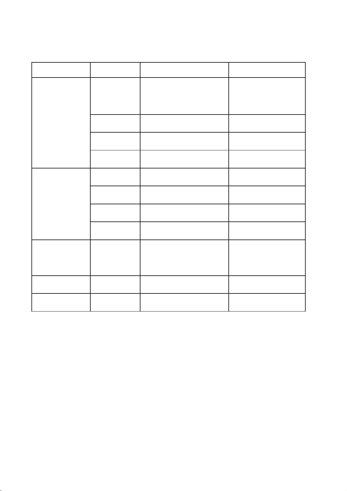
characteristic for sensors
model part number part name characteristic
1.R25=5KΩ±1%,
001A3900153 ambient temp sensor
AU282XHBAA
AU422XIBAA
AF- 001A3900059 coil temp sensor
AE- 001A3900006 gas pipe temp sensor
AB- 001A3900006 gas pipe temp sensor
0010450243 A system coil temp sensor
0010450398
0010451344
0010451343
0010450243 A system coil temp sensor
0010450398
0010451344
A system discharging temp
sensor
B system discharging temp
sensor
ambient temp sensor, B
system coil temp sensor
A system discharging temp
sensor
B system discharging temp
sensor
B25/50=3450K±1%
2.R25=5KΩ±1%,
B25/50=3450K±1%
R25=5KΩ±1%,
B25/50=3450K±1%
R80=50KΩ±3%,
B25/80=4450K±3%
R80=50KΩ±3%,
B25/80=4450K±3%
R25=5KΩ±1%,
B25/50=3450K±1%
R25=5KΩ±1%,
B25/50=3450K±1%
R80=50KΩ±3%,
B25/80=4450K±3%
R80=50KΩ±3%,
B25/80=4450K±3%
1.R25=10KΩ±3%,
B25/50=3700K±3%
2.R25=23KΩ±2.5%,
B25/50=4200K±3%
R25=10KΩ±3%,
B25/50=3700K±3%
R25=10KΩ±3%,
B25/50=3700K±3%

SAFETY PRECAUTIONS
3 SAFETY PRECAUTIONS
Please read these "Safety Precautions" first then accurately execute the installation work.
Though the precautionary points indicated herein are divided under two headings, and
those points which are related to the strong possibility of an installation done in error
CAUTION
resulting in death or serious injury are listed in the section. However, there is also a
possibility of serious consequences in relationship to the points listed in the section as well.
In either case, important safety related information is indicated, so by all means, properly observe all that is mentioned.
After completing the installation, along with confirming that no abnormalities were seen from the operation tests, please
explain operating methods as well as maintenance methods to the user (customer) of this equipment, based on the owner's
manual.
Moreover, ask the customer to keep this sheet together with the owner's manual.
WARNING
WARNING
CAUTION
WARNING
This system should be applied to places of office, restaurant, residence and the like. Appliaction to inferior
environment such as engineering shop could cause equipment malfunction.
Please entrust installation to either the company which sold you the equipment or to a professional contractor.
Defects from improper installations can be the cause of water leakage, electric shocks and fires.
Execute the installation accurately, based on following the installation manual. Again, improper installations can
result in water leakage, electric shocks and fires.
When a large air-conditioning system is installed to a small room, it is necessary to have a prior planned
countermeasure for the rare case of a refrigerant leakage, to prevent the exceeding of threshold concentration.
In regards to preparing this countermeasure, consult with the company from which you purchased the equipment,
and make the installation accordingly. In the rare event that a refrigerant leakage and exceeding of threshold
concentration does occur,there is the danger of a resultant oxygen deficiency accident.
For installation, confirm that the installation site can sufficiently support heavy weight. When strength is insufficient,
injury can result from a falling of the unit.
Execute the prescribed installation construction to prepare for earthquakes and the strong winds of typhoons and
hurricanes, etc. Improper installations can result in accidents due to a violent falling over of the unit.
For electrical work, please see that a licensed electrician executes the work while following the safety standards
related to electrical equipment, and local regulations as well as the installation instructions, and that only exclusive
use circuits are used.
Insufficient power source circuit capacity and defective installment execution can be the cause of electric shocks and
fires.
Accurately connect wiring using the proper cable, and insure that the external force of the cable is not conducted to
the terminal connection part, through properly securing it. Improper connection or securing can result in heat
generation or fire.
Take care that wiring does not rise upward, and accurately install the lid/service panel. Its improper installation can
also result in heat generation or fire.
- 10 -
SAFETY PRECAUTIONS
WARNING
When setting up or moving the location of the air conditioner, do not mix air etc. or anything other than the designated
refrigerant (please see nameplate) within the refrigeration cycle.
Rupture and injury caused by abnormal high pressure can result from such mixing.
Always use accessory parts and authorized parts for installation construction. Using parts not authorized by this
company can result in water leakage, electric shock, fire and refigerant leakage.
The position of indoor unit must be above the floor 2.5m.
CAUTION
Execute proper grounding. Do not connect the ground wire to a gas pipe, water pipe, lightening rod or a telephone
ground wire.
Improper placement of ground wires can result in electric shock.
The installation of an earth leakage breaker is necessary depending on the established location of the unit. Not
installing an earth leakage breaker may result in electric shock.
Do not install the unit where there is a concern about leakage of combustible gas.
The rare event of leaked gas collecting around the unit could result in an outbreak of fire.
For the drain pipe, follow the installation manual to insure that it allows proper drainage and thermally insulate it to
prevent condensation. Inadequate plumbing can result in water leakage and water damage to interior items.
- 11 -

4. Net dimension of indoor and outdoor
4.1 Outdoor unit: AU282XHBAA
340
830
380
416
>600
185
580
950
1024
>100
>100
>150
>600

4.2 Indoor units
Model: CONSOLE TYPE
Model: WALL MOUNTED TYPE
440
783
225
model
Haier
a
b
c
a
b
c
AS072XCBAA AS092XCBAA
AS122XCBAA AS142XCBAA
795
265
182

Model: CASSETTE TYPE
Model: CEILING CONCEALED TYPE
UPDATED
e
d
f
g
Installation dimension: (Unit: mm)
TYPE
AE072XCBAA,
AE122XCBAA,
AE212XCBAA
AE092XCBAA
AE142XCBAA
c
b
a
a b c d e f g i
615
770
1064
648
804 225
1099
452
452
452
225
225
55
55
55
125
225
125
225
225 100
125
i
100
100

The unit capacity and performance mode:
(A stands for A system, B stands for B system. For testing result, we will not recommend 12000BTU/h unit to you)
AU282XHBAA+072XCBAA*4 as followings:
A:
AF072*1
cooling
heating
Performance mode
Nominal capacity(BTU/h) 12000 12000 14000 14000 28000
Rated power input(W): 1550 1550 1550 1550 3100
Rated current(A) 7.5 7.5 7.5 7.5 15.0
Nominal capacity(BTU/H) 9000 9000 16000 16000 32000
Rated power input(W): 1800 1800 1500 1500 3000
Rated current(A) 9.0 9.0 7.0 7.0 14.0
AS072*1
AB072*1
AE072*1
AU282XHBAA+092XCBAA*4 as followings:
A:
AF092*1
cooling
heating
Performance mode
Nominal capacity(BTU/h) 12000 12000 14000 14000 28000
Rated power input(W): 1550 1550 1550 1550 3100
Rated current(A) 7.5 7.5 7.5 7.5 15.0
Nominal capacity(BTU/H) 9000 9000 16000 16000 32000
Rated power input(W): 1800 1800 1500 1500 3000
Rated current(A) 9.0 9.0 7.0 7.0 14.0
AS092*1
AB092*1
AE092*1
AU282XHBAA+07XCBAA*2+14XCBAA*1
B:
AF072*1
AS072*1
AB072*1
AE072*1
B:
AF092*1
AS092*1
AB092*1
AE092*1
A:
AF072*2
AS072*2
AB072*2
AE072*2
A:
AF092*2
AS092*2
AB092*2
AE092*2
B:
AF072*2
AS072*2
AB072*2
AE072*2
B:
AF092*2
AS092*2
AB092*2
AE092*2
A:
AF072*2
AS072*2
AB072*2
AE072*2
A:
AF092*2
AS092*2
AB092*2
AE092*2
B:
AF072*2
AS072*2
AB072*2
AE072*2
B:
AF092*2
AS092*2
AB092*2
AE092*2
cooling
heating
A:
AF072*1
Performance mode
Nominal capacity(BTU/h) 12000 14000 14000 28000
Rated power input(W): 1550 1550 1550 3100
Rated current(A) 7.5 7.5 7.5 15.0
Nominal capacity(BTU/H) 9000 16000 16000 32000
Rated power input(W): 1800 1500 1500 3000
Rated current(A) 9.0 7.0 7.0 14.0
AS072*1
AB072*1
AE072*1
B:
AF142*1
AS142*1
AB142*1
AE142*1
A:
AF072*2
AS072*2
AB072*2
AE072*2
A:
AF072*2
AS072*2
AB072*2
AE072*2
B:
AF142*1
AS142*1
AB142*1
AE142*1

AU282XHBAA+09XCBAA*2+14XCBAA*1
cooling
heating
A:
AF092*1
Performance mode
Nominal capacity(BTU/h) 12000 14000 14000 28000
Rated power input(W): 1550 1550 1550 3100
Rated current(A) 7.5 7.5 7.5 15.0
Nominal capacity(BTU/H) 9000 16000 16000 32000
Rated power input(W): 1800 1500 1500 3000
Rated current(A) 9.0 7.0 7.0 14.0
AS092*1
AB092*1
AE092*1
B:
AF142*1
AS142*1
AB142*1
AE142*1
A:
AF092*2
AS092*2
AB092*2
AE092*2
AU282XHBAA+142XCBAA*2 as followings:
A:
cooling
heating
AF142*1
Performance mode
Nominal capacity(BTU/h) 14000 14000
Rated power input(W): 1550 1550
Rated current(A) 7.5 7.5
Nominal capacity(BTU/H) 16000 16000
Rated power input(W): 1500 1500
Rated current(A) 7.0 7.0
AS142*1
AB142*1
AE142*1
AF142*1
AS142*1
AB142*1
AE142*1
Must pay special attention to the match style, to see the following table:
A to 2 B to 2 A to 1 B to 1
072XCBAA*2 072XCBAA *2
142XCBAA *1 142XCBAA *1
092XCBAA*2 092XCBAA*2
Pipe connections:
AF092*2
AS092*2
AB092*2
AE092*2
B:
A:
B:
AF142*1
AS142*1
AB142*1
AE142*1
1 TO 4
Outdoor unit
A1
A2
B1
B2
A1
A2
Indoor units
B1
B2

1 TO 3
Outdoor unit
A1
A2
B1
B2
1 TO 2
Outdoor unit
Indoor units
A1
A2
Indoor units
B1
A1 B1
A1
A2
B1
B2
Admissible pipe length and drop between the units:
a. Max. single distance piping length of unit A 1、unit A2 、unit AB1、unit B2: 25m;
b. Max. drop between A1 unit and A2 unit、B1unit and B2 unit:5m;
Refrigerant recharge:
Distribute pipes for unit A1、unit A2、unit B1、 unit B2 are supplied 5m as standard, if it is longer than 5m,
recharge refrigerant as 35g/m.
Communication Wire connection:
1. The indoor unit whose liquid pipe is connected to A1 in A system is called unit A1, its communication wire
of A1(3)、 A1(4) should be connected to A1(P)、A1(Q) respectively.
2. The indoor unit whose liquid pipe is connected to A2 in A system is called unit A2, its communication wire
of A2(3) 、A2(4) should be connected to A2(P)、A2(Q) respectively.
3. The indoor unit whose liquid pipe is connected to B1 in B system is called unit B1, its communication wire
of B1(3) 、B1(4) should be connected to B1(P)、B1(Q) respectively.
4. The indoor unit whose liquid pipe is connected to B2 in B system is called unit B2, its communication wire
of B2(3) 、B2(4) should be connected to B2(P)、B2(Q) respectively.
Note: Because the customers themselves match the communication wire, and the P and Q are
nonpolar, the customers must use shielded communication wires.

ky*r{ pnovr nxq pyxxrp}uxs pnovrg
jy{ fbbbhlmat ,cehlmat ~xu}|g
XW[QY PNOTQ
>/5GC,<62= 0-4UU
jy{ wy{r }tnx dcbbbhlmat ~xu}|g
XW[QY PNOTQ
>/5GC,<62= 1-/UU
iyxxrp}uxs *u{uxs quns{nwg
jy{ pn||r}}r nxq q~p}` pyx|yvr }+zr ~xu}|g
DJI:DDG JC?I
I;GB?C?7A 8AD9@
?C:DDG JC?I
I;GB?C?7A 8AD9@
PWVVQPZSVR PNOTQ
1
>/3GC,< 6/-54UU1\1
PWVVQPZSVR PNOTQ
1
>/3GC,< 6/-54UU1\1
AC
L8
M.=
EDL;G HJEEAM6
0E>+11/,12/K^+4/>]
0123
M.=
70 71 80 81
EFEFEFEF
M.=
0123
M.=
0123
EDL;G HJEEAM6
0E>+11/,12/K^+4/>]
0123
M.=
M.=
jy{ *nvv }+zr ~xu}|g
DJI:DDG JC?I
I;GB?C?7A 8AD9@
?C:DDG JC?I
I;GB?C?7A 8AD9@
AC
L8
M.=
EDL;G HJEEAM6
0E>+11/,12/K^+4/>]
32 10
EDL;G HJEEAM6
0E>+11/,12/K^+4/>]
M.=
EDL;G HJEEAM6
0E>+11/,12/K^+4/>]
EDL;G HJEEAM6
0E>+11/,12/K^+4/>]
70 71 80 81
EFEFEFEF
32 10
M.=
EDL;G HJEEAM6
0E>+11/,12/K^+4/>]
M.=
EDL;G HJEEAM6
0E>+11/,12/K^+4/>]
32 10
EDL;G HJEEAM6
0E>+11/,12/K^+4/>]
32 10
EDL;G HJEEAM6
0E>+11/,12/K^+4/>]
M.=
M.=

5. Installation
Installation diagram of indoor & outdoor unit
Outdoor unit
Piping data.
Gas pipe mm 12.7
L1 m Suggest 10m Max. :30m
Pipe length of one way L2 m Suggest 10m Max. :25m
L3 m Suggest 10m Max. :25m
Drop between indoor Indoor unit up m Suggest 5m Max. :15m
and outdoor unit Indoor unit down m Suggest 5m Max. :10m
No need to recharge: when piping length of one way is less than 5 meters.
1
L1 means the piping length when the system only connects with one indoor unit.
2
L2, L3 means the piping length when the system connects with 2 indoor units.
3
Long piping length and large drop between indoor unit and outdoor unit will reduce the
performance capacity obviously.
A 2
L1
AS142
L2
B 1
B 2
AS072
AS092
3
3
3
3
3
L3
1
2
2
Installation tools
1. Screw
2. Steel saw
3. Drill (70mm dia.)
4. Spanner [17, 27mm dia.]
5. Spanner [14, 17, 19, 27mm]
6. Pipe cutter
7. Flarer
8. Knife
9. Pliers
10. Leakage detector or soap water
11. Tape measure
12. Scraping knife
13. Refrigerant oil
14. Vacuum pump
15. Nitrogen tank
Standard accessories
The following parts mentioned
in this instruction is optional.
The following are accessories attached with the unit,
they can be used with the need of installation
Shape, name
Rubber cushion
Quantity Remarks
4
1
1
Mark
,
Parts name
A B C D E F
Adhesive
tape
Pipe supporting
plate
Connection pipe
Drain hose
Insulation material
Powder

5. Installation
Installation instruction
Before installing, do read this Safety precautions carefully to guarantee the proper installation.
The below attentive matters are divided into Warning and Note two parts. When the
wrong installation occur, it is very possible death and severe injury and other serious accidents will
happen. For those items are listed in Warning part. But even the items listed in Note
part can also cause serious accidents. Above all, both the two parts are very important contents
related to safety, so they must be obeyed.
After finishing the installation work, do test run to verify everything is normal. After that please
explain the using and maintenance methods to the user. Additionally, give this installation manual
and operation manual to the user and ask them to keep it properly.
!
The distributing shop, where you bought the air conditioner, or the specified shops shall do the
installation work. If you do the installation work by yourself, the improper installation will cause
water leakage, electric shock fire and other accidents.
The installation work shall be in line with what the installation manual specified. If installation
is not proper, water leakage, electric shock, fire and other accidents will occur.
Install the air conditioner to a place where can definitely stand its weight. Places not firm enough
will cause drop down of unit resulting in body hurt.
The installation work shall be preventive to typhoon and earthquake. If the installation work is
not met with the requirements, overturn of the unit will occur resulting in accidents.
The wiring work shall be done by a qualified person and referred to the technical standard of
electric equipment , indoor wiring regulation and what the manual specified. Do use
special circuit. If the capacity of the circuit is not enough or bad work, electric shock, fire and other
accidents will happen.
Using the specified cable to do wiring work and connecting firmly and properly. Fix the connecting
part of the terminals to prevent it from the external force.Improper connection and fixing will cause
heating and fire etc. accidents.
Wiring shall be kept in correct shape avoiding extrusion. After installation, the electric box cover
and the external panel shall not nip the wire. Improper installation will cause heating and fire etc.
accidents.
When setting or moving the air conditioner do not let the air and things alike get into the
refrigeration system except the specified refrigerant (R407C). If air and other things enter
abnormal high pressure will occur, which easily cause break and body injuries etc. accidents.
When installing, do use the accessories or specified parts. If not using the parts specified by our
company, water leakage, electric shock, fire and refrigerant leakage will occur.
Do not lead the drainpipe to drain where the sulfur gas may be involved. Otherwise, the poisonous
gas will enter into the indoor.
During installation, if refrigerant leakage occurs, do the ventilation work immediately. As soon as
the refrigerant gas meets fire, poisonous gas will be produce. If the refrigerant gas enters into room
and meet the air blowing heater, heater or stove etc. fire source, the poisonous gas may be produced.
After installation, confirm there is no leakage of refrigerant.
Do not install the unit in a place where the combustible gas may be leaked. In any case the
combustible gas leaks and accumulated around the unit, fire accident will occur.
Do heat insulation work to the refrigerant gas pipes and liquid pipes to reach the purpose of heat
preservation. If the heat insulation measure is not sufficient, water generated by condensing dew
will drip leading to wet the floor and indoor articles.
!
!
Warning
!
!
!
Note
Do grounding work.Do not connect the grounding wire to gas pipe,tap,lighting rod or telephone
line.Improper grounding will cause electric shock.
After electric installation,power on them to do electric leakage test.
In some places the creepage breaker shall be installed.If do not install the breaker, electric shock
may occur.

Installation of outdoor unit
Choosing of installation position
Installation position
Do not install the air
conditioner near to a
place where flammable
gas may leak.
Explosion may be caused
(fire)
Choose a place where the
cold/heat air or noise may
not disturb the neighbors.
Install the air conditioner in a
place where good ventilation
can be guaranteed.
If there are some obstacles,
it may lower the working
power of the unit or
increase noise.
It is deadly necessary to
prevent from accumulation
of snow near the outdoor
unit to keep it away from
being blocked by
accumulated snow.
Install the air conditioner on base
that can definitely support the weight
of the unit.
Otherwise, vibration or noise may
be caused.
The following special places are not
suitable to install air conditioner,
otherwise, trouble may be caused.
When you install the air conditioner
in these places, please consult with
the distributor.
Places generate corrosive gas
(hotspring area, etc.)
Places blow salt air (seaside, etc.)
Places have heavy soot.
Places have very high humidity.
Places near an electromagnetic
wave generator.
Places with large voltage fluctuation.
Installation fixation
1. According to dimonsion shown in the following figure,
fix the installation bracket tightly in the chosen
installation area.
2. Then use screws to fix the outdoor unit on the
installation bracket.
380
190 190
Installation dimension of outdoor unit (mm)
580
Over 60cm
>10cm
>10cm
Outdoor unit
>15cm
>60cm

Installation procedure Connection of pipes
Warning
!
During installation, if refrigerant leakage
occurs, take ventilation measurement
immediately.
As soon as the leaked refrigerant gas
meets f re, poisonous gas will generate.i
After finishing installation, confirm the
refrigerant gas does not leak.
If the refrigerant gas leaks in the room,
once it meets heater, burner and gas
stove or other. fire source, the poisonous
gas will generate.
I. Connection of pipes
1 Method of pipe connection
The pipe shall be as short as possible to guarantee efficiency.
Daub the refrigerant oil on the connection and flare nut.
When bending the pipes, give the roundness as large as possible, to avoid crashing the
pipes.
To connect the pipe, fit the center and screw the nut with hand, then use spanner or
torque wrench to tighten it. The fastening torque as shown in below table. As shown in
figure.
Be careful alien matters, such as sands, water etc.shall not enter the pipes.
Forced fastening without careful
centring may damage the threads
and cause gas leakage.
Using the specified fastening torque to fasten nuts.
Pipe diameter(mm)
6.35
12.7
Installation torque(N.m)
11.8(1.2kgf.m)
49.0(5.0kgf.m)
Spanner
Spanner
Joint
Nut
Fastening torque(N.m)
13.7(1.4kgf.m)
53.9(5.5kgf.m)

Installation procedure Connection of pipe
2.Method of cutting and flaring pipe
Cut and flare pipe
Use pipe cutter to cut the pipe, the burrs must be removed.
After inserting the flarer, perform flared nut.
Flaring pipes.
A
Flarer
Correct
Slant
When joint connecting, no gap shall
be left in the joint, the insulating
material shall be overlapped.
Break Crack
150
Diameter of pipe
6.35mm(1/4")
12.70mm(1/2")
Uncorrect
Branch pipe
Insulating material
Partial
Dimension
(mm)
A
0.8~1.5
1.0~2.0
Too outside
Connecting pipe in site
Insulating material
Insulating material (arranged in site)
Thickness: Over 10mm

Installation procedure Connection of pipes
4.Pipe connection of the outdoor unit.
Referring to the installation diagram in page 4, connect the indoor unit with outdoor unit, by
using the pipe connection method.
II Test of airtight quality
After connection of the refrigerant pipes, carry out airtight quality test. In this test, pressurize to the
pipes as shown in the below figure by using nitrogen tank.
Close the valves of the gas side and liquid side totally.
The nitrogen may enter the cycle system of the outdoor unit, so that, before pressurizing, the valve rods
must be fastened.(Both the gas side and liquid side)
For each of the refrigerant system, pressurize from the discharge valve of gas side in procedure.
When doing airtight quality test, it is absolutely forbidden to use oxygen, flammable gas and poisonous
gas.
If the hi-pressure valve of the outdoor unit is 3-way valve.
Stop valve close
Indoor side
Joint
Joint
Outdoor side
Welding part
Welding part
Fasten
Fasten
(Gas side)
Gas discharging
valve
Indoor unit
Stop valve close
(Liquid side)
When the hi-pressure valve of the outdoor unit is 2-way valve.
3-way valve close
Indoor side Outdoor side
Welding part
Joint
(Gas side)
Fasten
Low pressure
meter
Gas discharging valve
Outdoor unit
Low pressure
meter
Gas discharging valve
High pressure
meter
VL VH
Instrument
distributor
Pressure
reducing
valve
High pressure
meter
VL VH
Instrument
distributor
Nitrogen
Indoor unit
Joint
Welding part
Fasten
Outdoor unit
2-way valve
(Liquid side)
Pressure
reducing
valve
Nitrogen

Installation procedure Connection of pipes
III Vacuumizing of the pipes and indoor unit (using vacuum pump to vacuumize, it is strictly
forbidden to use refrigerant purging)
Choose of vacuum pump: it shall choose those that can reach a good vacuity ( Lower 200Pa ) and
have a large air discharge amount (over 40L/min).
After finishing the airtight quality test and discharging the nitrogen, connect the instrumental
diverter to the 3-way discharge valve, then connect the vacuum pump according to the below figure.
If the hi-pressure valve of the outdoor unit is 3-way valve.
Indoor side
Outdoor side
Low pressure
meter
Stop valve close
(Gas side)
VL VH
High pressure
meter
Instrument
distributor
Fasten
Fasten
Fasten
Fasten
Indoor unit
Stop valve close
(Liquid side)
When the hi-pressure valve of the outdoor unit is 2-way valve .
Indoor side
Outdoor side
Joint
Fasten
Joint
Fasten
Gas discharging valve
Gas discharging
valve
Outdoor unit
Low pressure
3-way valve close
meter
(Gas side)
Gas discharging valve
P
Vacuum pump
High pressure
meter
VL VH
Instrument
distributor
P
Indoor unit
Outdoor unit
2-way valve
(Liquid side)
When the hi-pressure valve of the outdoor unit is 2-way valve:
(1) Firstly connect indoor, outdoor power supplies, and communication lines, then set addresses
of indoor units and check their correctness.
(2) Determine running mode according to indoor temperature: Set to cooling mode when indoor
temperature Ta 23 set to heating mode when Ta<23 .
(3) Keep stop valve of outdoor unit close , and start the indoor unit according to running mode
determined by indoor temperature.
Vacuum pump

Installation procedure Connection of pipes
(4) Watch the status of outdoor unit compressor, disconnect the general power supply for the air
conditioner assembly after the compressor unit starts.
If the hi-pressure valve of the outdoor unit is 3-way valve:
Without starting the machine, simply exhaust to vacuum (vacuum degree<200Pa) directly from
hi-presser and low-pressure valves(strictly in compliance with operation steps defined in instruction
manual for outdoor unit) after machine connecting pipe is well done.
Vacuumize 2~3 hours according to the length of the pipe. When vacuumizing, confirm the gas side
and liquid side of the 2-way valve and 3-way valve shall be in full close state.
When it is not lower than 200Pa after 2 hours or more vacuumizing, vacuumize for another
1 hour. If after more than 3 hours vacuumizing it is still not lower than 200Pa, the leak part shall be
found.
When it is lower than 200Pa after more than 2 hours vacuumizing, close both the valve VL and
VH of the diverter, then close the vacuum pump. Place it there to observe if the vacuity changes.
If it changes, it indicates leakage exists, so the leak part shall be found.
After finishing the above vacuumizing work, replace the vacuum pump with refrigerant tank and
turn to the refrigerant charging procedure.
V Charging of refrigerant
1.Calculation of additional charging amount of refrigerant
After finishing vacuumizing work, replace the vacuum pump with refrigerant tank and turn to the
refrigerant additional charging procedure.
Calculation of additional charging amount of refrigerant
Quantity of filled refrigerant before the machine leaving factory does not consider supplement
for extension tubes while spot installation. After practical installation is finished, it is necessary to fill
supplement refrigerant into extension tubes provided that the length of spot liquid tube>0m.
Filling method is as the following.
Calculation method:
Quantity of supplement refrigerant is determined by specification and actual length of the spot
liquid tube.
Calculation formula:
Quantity of spot supplement refrigerant = actual length necessary supplement refrigerant
quantity per meter of the tube.
E.g.: Uuantity of spot supplement refrigerant(R407C)=(L1-5) 0.035kg/m)
L1: Actual total length of 6.35 liquid tube in one system
Uuantity of spot supplement refrigerant(R407C)=[(L2-5)+(L3-5)] 0.035kg/m)
L2, L3: Actual length of 6.35 liquid tube in the B1, B2 way.
2.Charging of refrigerant
Close all valves of outdoor unit, and charge refrigerant from air discharge valve of gas side.
When can not charge the specified amount, firstly, open all the valves, both liquid side and gas side,
of outdoor unit,then switch the valve of gas side to close state a little.Under this condition, do cooling
operation and charge refrigerant from the discharge valve of gas side. At this time, adjust the valve
of the refrigerant tank to make the refrigerant in Gas State when it is absorbed by system.
When refrigerant leakage making refrigerant lack in system occurs, all of the system shall be
recovered and recharge it according to specified amount.
3.Opening of the refrigerant pipe
Open all the valves of outdoor unit

Installation procedure Refrigerant
The systems use regrigerangt R407C. This refrigerant itselt is innocuous, noncombustible safety
refrigerant. But then, when arranging the air conditioner equipment, it is necessary to take some
steps to take precautions against in case of the indoors refrigerant leakage. Such as, the room
size shall be taken into account to avoid making the concentration of the refrigerant not exceed the
concentration limit and other relevant steps. The concentration limit is the concentration that is not
harmful to human body and can take emergency steps to treat the concentration of Freon.
Concentration limit of R407C:0.3kg/m
3
Indoor unit
Indoor unit
If the indoor unit leaks, all the refrigerant in
the syetem will leak out
1.Sequence of refrigerant concentration affirmance
Calculate the refrigerant concentration according to the following sequence.
(1) Calculate the total refrigerant-charging amount of each of the refrigerating system(kg).
Refrigerant charging amount of outdoor system + Additional refrigerant charging amount
=Total refrigerant charging amount of the refrigerating equipment(kg).
Refrigerant charging amount of outdoor system: Refrigerant charging amount when air
conditioner leaves factory.
Additional refrigerant charging amount: Additional refrigerant charging amount according
to the site pipe length and pipe diameter.
(2) Calculate the minimum size of the room suitable for the indoor unit assembly(m ).
3
(3) Calculate the concentration of refrigerant:
Total refrigerant charging amount of refrigerating equipment/the minimum room size suitable
for indoor unit assembly(m ) Refrigerant concentration limit:0.3kg/m
3
3
2.Countermeasure when exceeding the concentration limit
(1) Set an effective opening for ventilation and fresh air.
Cut an intake respectively on the upper and lower part of the door which areas are equivalent
to 0.15% grounding area, or cut an intake in other part of the room.
(2) Reduce the total refrigerant charging amount of the refrigerating equipment
Shorten the refrigerant pipe length. Reduce the installation place distance between the
outdoor unit and the indoor unit to shorten the refrigerant pipe length, so that reduce the
total refrigerant charging amount of the refrigerating equipment.
(3) Establish ventilation and fresh air system
Establish a mechanical equipment for fresh air to keep the refrigerant concentration below
the concentration limit (normal ventilation).
When can not ventilate the normally, please set an alarm apparatus linked with the
mechanical ventilation equipment.
Installation procedure Electric wiring
Electric wiring
Note:
The air conditioner must use special circuit (over 30A), and wiring by the qualified
electrician according to the wiring rules specified in national standard.
The grounding wire and the neutral wire shall be strictly separated. Connect the neutral
wire with grounding wire is incorrect.
The electric leakage breaker must be installed.
All the electric wire must be copper wire.When wiring,there shall keep a proper distance
between the power line and communication wire to avoid twist together.Otherwise,signal
disturbance will occur,and the air conditioner can not operate normally.
Power supply:1PH,220-230V~,50Hz.
The wiring method of power line is Y connection. If the power line is damaged,in order
to avoid risk of electric shock, it must be replaced by the manufacturer or its repair center
or other similar qualified person.
Specification of wire and short circuit protector in site wiring:
Fuse: 30A 250VAC
Type
Contents
Specificat on
i
Parameter
Power line
YZW
3x3.0mm
Short circuit
protector
2
30A
Connection signal wire
2x(0.75~1.25mm )
Note:The signal wire must be shielded .
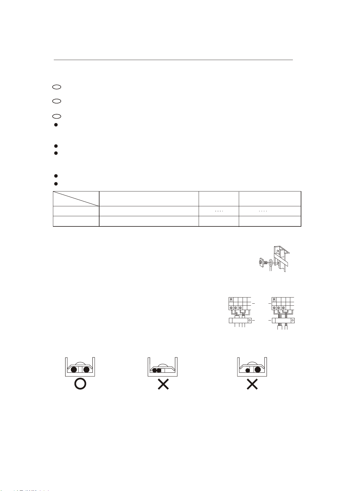
Wiring method
1. Wiring method of orbicular terminals
For the connection wire with orbicular terminals, its wiring method
is as shown in the right figure: remove the connecting screw, put the
screw through the ring on the end of the wire, then connect to the
terminal block and fasten screw.
2. Wiring method of straight terminals
For the connection wire without orbicular terminals, its wiring
method is: loosen the connection screw, and insert the end of
the connection wire completely into the Termina l block, then
fasten the screw. Slightly pull the wire outwards to confirm it is
firmly held
3. Crimp connection method for wires without terminals
Connect the wire with
same diameter to the
two sides of the terminal
Do not connect the
wire with same diameter
to the same side
Correct Pressing
Do not connect the
wire with different
diameters
Wiring Method for
Ring Terminal Block
Wrong Pressing
Terminal
block
Pressing
Clamps
2
Crimp connection method for connection wire
After connection,the wire must be fastened by wire cover. The wire cover shall press on the
protection coat of the connection wire,as shown in right top figure.
Note:When connecting the wiring,confirm the terminal number of indoor and outdoor units
carefully. Incorrect wiring will damage the controller of air conditioner or the unit can not
operate.

Installation procedure Electric wiring
Wiring method of outdoor unit:
Power line
Remove the repair board of the outdoor unit and loosen the wire cover A,then put the live
wire, neutral wire and grounding wire through the wire cover A,and connect them to
terminal block correspondingly. After connection, fasten wire cover A to its previous
state.
Communication wire of indoor unit
Loosen wire cover B ,put the communication wire through the wire cover B, and connect
them to terminal block correspondingly. After connection, fasten wire
cover B to its previous state.
Note: Power line and communication wire are provided by consumers themselves.
Termial
Wring clamp
B
A
Wiring method of indoor unit
Power line and communication wire of indoor unit
Loosen wire cover and connect the power line and communication wire of indoor unit to
the terminal correspondingly.
 Loading...