

Haier AU242FHBIA, AU482FIBIA, AU48NFIBJA AC Schematic
Commercial Air Conditioning
SERVICE MANUAL
Models
AU242FHBIA
AU482FIBIA
AU48NFIBJA
And its indoor units
zFeatures
zNew cassette unit, with 700*700 panel and new unit body
zNew PCB for cassette indoor unit and outdoor unit, much stabler
zMutiple indoor unit types: cassette type, ceiling concealed type, and wall
mounted type
zFree combination, total indoor capacity can be 50%~130% of outdoor capacity
zMultiple control types, infrared control+wired control
zIndividual operation for every indoor uint, energy saving
zNew refrigerant control device: MP2A, MP3A
zAuto restart function
zLong piping and high drop between indoor and outdoor
zRefrigerant: R407C
Manual code: SYJS-017-05REV.0 Edition: 2005-11-22

Commercial Air Conditioner Model: AU242FHBIA,
AU482FIBIA, AU48NFIBJA
CONTENTS
Contents………………………………………………………...2
1. Description of products & features………………………..3
2. Specification…………………………………………………6
3. Safety precaution…………………………………………...14
4. Net dimension……………………………………………….16
5. Installation instructions………..……………………………21
6. Parts and functions………………………………………….53
7. Controller functions.............………………………………..21
8. Electrical control functions…………………………………71
9. Wiring diagrams…………………………………………….95
10. Failure code and troubleshooting………………………..99
11. Noise level……………………………………...................121
12. Performance curves......................................................124
-2-
Commercial Air Conditioner Model: AU242FHBIA,
AU482FIBIA, AU48NFIBJA
1.DESCRIPTION OF PRODUCTS & FEATURES
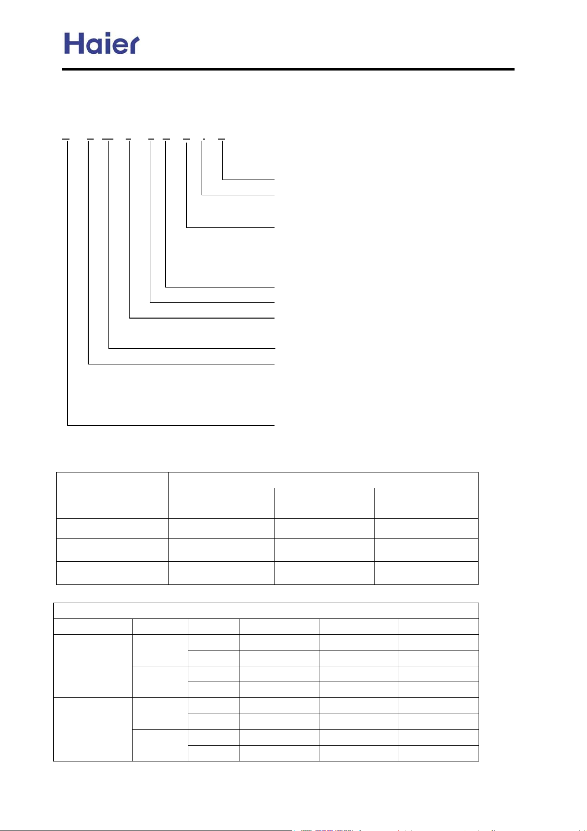
1.1. Products code explanation
A B 14 2 F C B I A
Climate type: T1 (see table 1)
Design number (I stands for design sequence, inverter
frequency type)
Product type: A stands for heat pump type, refrigerant is R22
B stands for heat pump type, refrigerant is R407C
M stands for cool only type, refrigerant is R22
N stands for cool only type, refrigerant is R407C
Appearance code
Product series: F stands for MRV
Applicable voltage: 2 stands for 220-230V/50Hz,
4 stands for 220V/60HzˈN stand for 380-400V/50Hz
Cooling / Heating capacity,14=14000BTU/h
Product type : “B” stands for cassette type, “C” stands for
convertible type, ”D” stands for duct, “S” stands for split
type, ”Q” stands for chiller system, "E" stands for ceiling
concealed type, “U” stands for outdoor unit
Air Conditioner
1.2 Brief Introduction for T1ǃT2ǃT3 working condition
Climate type
Type of Air
Conditioner
Cooling Only
Heat pump
Electricity Heating
T1 T2 T3
18 ć~43ć 10ć~35ć 21ć~52ć
-7ć~43ć -7ć~35ć -7ć~52ć
~43ć ~35ć ~52ć
1.3 Operating Range of Air Conditioners
Working temperature range
Rated Maximum Minimum
Cooling
Heating
Indoor
outdoor
Indoor
outdoor
DBć
WBć
DBć
WBć
DBć
WBć
DBć
WBć
27 32 18
19 23 14
35 43 -5
24 26 --
20 27 15
14.5 -- --
7 24 -15
6 18 --
-3-
Commercial Air Conditioner Model: AU242FHBIA,
AU482FIBIA, AU48NFIBJA
1.4 Product features
New designed panel 700*700 with the 600*600 cassette unit
New designed swing louver with the non smooth surface, which can hold back the condensant water.
New designed filter lock, which will fix the filter more firmly than before.
Adopts the stepping motor, give the louver a larger swing angel.
New fan with bigger diameter fan blade, sending out larger air flow.
The cassette indoor unit adopts the panel whose dimension is identical to that of ceiling, after installation,
the unit will be accordant with the decoration decor.
Free combination, total indoor capacity can be 50%~130% of that of outdoor capacity
The outdoor unit can match with all types of indoor unit with the allowable capacity, such as the cassette
type, the ceiling concealed type, the wall mounted type, etc.
Optional control types: infrared remote controller and wired controller
The unit can be controlled by the smart infrared remote controller YR-H71, which can realize many
functions such as heating, cooling, fan, swing, fresh, health, filter up/down, electric heating, etc.
Furthermore, the remote controller can be compatible with many old controllers, more convenient for
utilizing.
If the unit is with wired controller YR-E06, which can realize remote control type by adding an infrared
controller YR-H71.
Auto-check function
The unit can display the malfunction codes on the control board by using advanced auto-check
technology, convenient for user find and dwell with the abnormal running.
Auto–restart function (optional)
All indoor units have auto-restart function. When the power supply cut off suddenly, the unit will
automatically recover the previous running mode once the power supply is on.
New refrigerant control device: MP2A, MP3A
The new refrigerant control device MP2A and MP3A replace the previous device MP2 and MP3. The new
device includes gas pipe and liquid pipe, more convenient for installation than before.
-4-
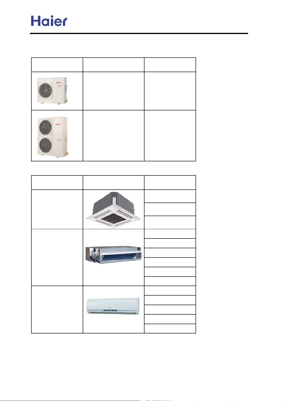
Commercial Air Conditioner Model: AU242FHBIA,
Total unit:
outdoor units
appearance model refrigerant
AU482FIBIA, AU48NFIBJA
indoor units
type appearance model
Four way cassette
AU242FHBIA
AU482FIBIA
AU48NFIBJA
R407C
R407C
AB092FCBIA
AB142FCBIA
AB182FCBIA
Ceiling concealed
Wall-mounted
(colorful screen)
AE072FCBKA
AE092FCBKA
AE122FCBKA
AE142FCBKA
AE182FCBKA
AE242FCBKA
AS072FCBHA
AS092FCBHA
AS122FCBHA
AS142FCBHA
AS182FCBHA
-5-
Commercial Air Conditioner Model: AU242FHBIA,
AU482FIBIA, AU48NFIBJA
2. SPECIFICATION
AU242FHBIA
Item Model AU242FHBIA
Function cooling heating
Capacity BTU/h
Capacity W
Total power input
Max. power input
EER or COP
W
W
W/W 2.2 2.55
Power cable
Power source
Running /Max.Running current
NˈVˈHz
A / A
Start Current A
Working frequency range Hz
Fuse A
Unit model (color)
Compressor
Model / Manufacture
Type
Type × Number
Fan
Speed r/min
Fan motor output power kW
Air-flow(H-M-L) m³/h
Type / Diameter mm
Heat exchanger
Dimension
Outdoor unit
Row*fin pintch
Temp. scope
External
Package
˄L×W×H˅
˄L×W×H˅
ć
mm×mm×mm
mm×mm×mm
Refrigerant control method mm/mm
Defrosting
Volume of Accumulator L
Noise level dB(A)
material of reduce noise
crankcase heater power W
Weight (Net / Shipping)
Refrigerant
Type / Charge g
kg / kg
Recharge quantity g/m
Pipe
Liquid mm
Gas mm
PIPING
Connecting Method
Between I.D &O.D
MAX.Drop
MAX.Piping length
m
m
24000 27000
7030 7910
3200 3100
3800 3800
2
6mm
1PH,220-230V~,50Hz
cooling: 18A/21A heating: 17/21A
--
30-105
3.15A 250V AC
AU242FHBIA (white)
C-7RB267H03AA/ SANYO SHENYANG
ROTARY
AXIAL*1
840±30/780±30/550±50
60*1
3240
inner grooved copper pipe ¶9.52
2*1.5mm
--
948X830X340
1050X979X440
EEV
AUTO
--
58
--
30
74/89
R407C/3200
ij9.52 liquid pipe: 65g/mhactual length
¶9.52
¶15.88
flared
outdoor upper: 30, outdoor lower: 20
50
-6-
AU482FIBIA
Commercial Air Conditioner Model: AU242FHBIA,
AU482FIBIA, AU48NFIBJA
Item Model
AU482FIBIA
Function cooling heating
Capacity BTU/h
Capacity W
Total power input
Max. power input
EER or COP
W
W
W/W
Power cable
Power source
Running /Max.Running current
NˈVˈHz
A / A
Start Current A
Working frequency range Hz
Fuse A
Unit model (color)
Compressor
Model / Manufacture
Type
Type × Number
Fan
Speed r/min
Fan motor output power kW
Air-flow(H-M-L) m³/h
Type / Diameter mm
Heat exchanger
Dimension
Outdoor unit
Row*fin pintch
Temp. scope
External
Package
˄L×W×H˅
˄L×W×H˅
ć
mm×mm×mm
mm×mm×mm
Refrigerant control method mm/mm
Defrosting
Volume of Accumulator L
Noise level dB(A)
material of reduce noise
crankcase heater power W
Weight (Net / Shipping)
Refrigerant
Pipe
PIPING
Connecting Method
Between I.D &O.D
Type / Charge g
Recharge quantity g/m
Liquid mm
Gas mm
MAX.Drop
MAX.Piping length
kg / kg
m
m
48000 61000
14000 18000
6500 6000
7500 7500
2.15 3.00
2
16mm
1PH,220-230V~,50Hz
cooling: 34A/42A heating: 30/40A
--
30-105
3.15A 250V AC
AU482FIBIA (white)
EEV48FAL1/MITSUBISHI ELECTRIC
SCROLL
AXIAL*2
920±30r/min/840±40r/min/560±50r/min
65*2
7480
inner grooved copper pipe ¶9.52
2*1.5mm
43-60
1250X948X340
1375X1050X440
EEV
AUTO
--
58
--
40
120/135
R407C/4200
ij9.52 liquid pipe: 65g/mhactual length
¶9.52
¶19.05
flared
outdoor upper: 30, outdoor lower: 20
100
-7-
AU48NFIBJA
Commercial Air Conditioner Model: AU242FHBIA,
AU482FIBIA, AU48NFIBJA
Item Model
Function
Capacity BTU/h
Capacity W
Total power input
Max. power input
EER or COP
W
W
W/W
Power cable
Power source
Running /Max.Running current
NˈVˈHz
A / A
Start Current A
Working frequency range Hz
Fuse A
Unit model (color)
Compressor
Model / Manufacture
Type
Type × Number
Fan
Speed r/min
Fan motor output power kW
Air-flow(H-M-L) m³/h
Type / Diameter mm
Heat exchanger
Dimension
Outdoor unit
Row*fin pintch
Temp. scope
External
Package
˄L×W×H˅
˄L×W×H˅
ć
mm×mm×mm
mm×mm×mm
Refrigerant control method mm/mm
Defrosting
Volume of Accumulator L
Noise level dB(A)
material of reduce noise
crankcase heater power W
Weight (Net / Shipping)
Refrigerant
Type / Charge g
kg / kg
Recharge quantity g/m
Pipe
Liquid mm
Gas mm
PIPING
Connecting Method
Between I.D &O.D
MAX.Drop
MAX.Piping length
m
m
AU48NFIBJA
cooling heating
48000 61000
14000 18000
6000 6000
7000 7000
2.33 3.00
2
4mm
3N~,380-400V,50Hz
cooling: 10.5A/13A heating: 10.5/13A
--
25-95
3.15A 250V AC
AU48NFIBJA (white)
AEV60FCHMT/MITSUBISHI ELECTRIC
SCROLL
AXIAL*2
920±30 r/min/840±40r/min/560±50r/min
65*2
7480
inner grooved copper pipe ¶9.52
2*1.5mm
43-60
1250X948X340
1375X1050X440
EEV
AUTO
--
58
--
40
120/135
R407C/4400
ij9.52 liquid pipe: 65g/mhactual length
¶9.52
¶19.05
flared
outdoor upper: 30, outdoor lower: 20
100
-8-
Commercial Air Conditioner Model: AU242FHBIA,
Indoor:
Item model
Cooling capacity Btu/h
Heating capacity Btu/h
Cooling capacity W
Heating capacity W
Dehumidifying capacity
Power source
Running current A
Starting current A
Refrigerant
Noise level(H/M/L) dB(A)
Type × Number
Fan
Heat exchanger
Refrigerant control method
Dimension(L×W×H)
Panel dimension (L×W×
H)
Weight(unit/panel)
Liquid mm (inch)
Piping
Suited area m2
Controller type
Gas mm (inch)
Connection method
Air-flow(H-M-L) m³/h
Fan motor output W
starting mothod
External
Shipping
External
Shipping
Net kg / kg
Shipping kg / kg
10ϋ³×m³/h
NˈVˈHz
mm×mm×mm
mm×mm×mm
mm×mm×mm
mm×mm×mm
AU482FIBIA, AU48NFIBJA
AB092FCBIA AB142FCBIA
9000 12000
11000 14000
2800 3600
3200 4000
1.6 2.1
1PH 220V-230V~ 50HZ 1PH 220V-230V~ 50HZ
-- --
11
R407C R407C
42/--/-- 42/--/--
centrifugal fan×1 centrifugal fan×1
700/--/-- 700/--/--
55 55
PG PG
Combination of wave cranny radiation fin and copper
Capillary + EEV
660×570×260 660×570×260
710×675×360 710×675×360
700×700×60 700×700×60
740×735×105 740×735×105
19.0/2.8 19.0/2.8
23.5/4.8 23.5/4.8
6.35 (1/4") 6.35 (1/4")
12.7 (1/2") 12.7 (1/2")
flared flared
12~23 17~27
remote controller
Item model
Cooling capacity Btu/h
Heating capacity Btu/h
Cooling capacity W
Heating capacity W
Dehumidifying capacity
Power source
Running current A
Starting current A
Refrigerant
Noise level(H/M/L) dB(A)
Type × Number
Fan
Heat exchanger
Refrigerant control method
Dimension(L×W×H)
Panel dimension (L×W×
H)
Weight(unit/panel)
Liquid mm (inch)
Piping
Suited area m2
Controller type
Gas mm (inch)
Connection method
Air-flow(H-M-L) m³/h
Fan motor output W
starting mothod
External
Shipping
External
Shipping
Net kg / kg
Shipping kg / kg
10ϋ³×m³/h
NˈVˈHz
mm×mm×mm
mm×mm×mm
mm×mm×mm
mm×mm×mm
AB182FCBIA
17000
19000
5000
5500
2.1
1PH 220V-230V~ 50HZ
--
1
R407C
42/--/--
centrifugal fan×1
700/--/--
55
PG
Combination of wave
cranny radiation fin and
copper pipe
Capillary + EEV
660×570×260
710×675×360
700×700×60
740×735×105
19.0/2.8
23.5/4.8
6.35 (1/4")
12.7 (1/2")
flared
22~33
remote controller
-9-
Commercial Air Conditioner Model: AU242FHBIA,
AU482FIBIA, AU48NFIBJA
Item model
AE072FCBKA AE092FCBKA
Cooling capacity Btu/h 7000 9000
Heating capacity Btu/h 9000 11000
Dehumidifying capacity
Power source
10ϋ³×m³/h
NˈVˈHz
1.2 1.6
1PH 220V-230V 50HZ 1PH 220V-230V 50HZ
Refrigerant R407C R407C
Noise level(H/M/L) dB(A) 36/32/29 36/32/29
Type × Number centrifugal fan×2 centrifugal fan×2
Fan
Air-flow(H-M-L) m³/h 520 / 420 / 300 520 / 420 / 300
starting mothod Relay control Relay control
Heat exchanger
Refrigerant control method
Dimension ˄L×W×H˅
Weight
External
Net kg 18 18
mm×mm×mm
Combination of wave cranny radiation fin and copper
Capillary + EEV
674×225×450 674×225×450
Liquid mm 6.35 6.35
Piping
Gas mm 9.52 9.52
Connection method flared flared
Suited area m2 8~16 11~21
Controller type
wired controller or remote controller
Item model
AE122FCBKA AE142FCBKA
Cooling capacity Btu/h 12000 14000
Heating capacity Btu/h 14000 16000
Dehumidifying capacity
Power source
10ϋ³×m³/h
NˈVˈHz
1.8 2
1PH 220V-230V 50HZ 1PH 220V-230V 50HZ
Refrigerant R407C R407C
Noise level(H/M/L) dB(A) 42/38/32 42/38/32
Type × Number centrifugal fan×2 centrifugal fan×2
Fan
Air-flow(H-M-L) m³/h 650 / 550 / 400 700/ 550 / 400
starting mothod Relay control Relay control
Heat exchanger
Refrigerant control method
Dimension ˄L×W×H˅
Weight
External
Net kg 20 20
mm×mm×mm
Combination of wave cranny radiation fin and copper
Capillary + EEV
828×225×450 828×225×450
Liquid mm 6.35 6.35
Piping
Gas mm 12.7 12.7
Connection method flared flared
Suited area m2 12~23 17~27
Controller type
wired controller or remote controller
-10-
Commercial Air Conditioner Model: AU242FHBIA,
z
Z
Z
AU482FIBIA, AU48NFIBJA
Item model
AE182FCBKA AE242FCBKA
Cooling capacity Btu/h 18000 24000
Heating capacity Btu/h 20000 28000
Dehumidifying capacity
Power source
10ϋ³×m³/h
NˈVˈH
Refrigerant
Noise level(H/M/L) dB(A)
2.4 3
1PH 220V-230V 50H
1PH 220V-230V 50H
R407C R407C
48 / 43 / 36 48 / 43 / 36
Type × Number centrifugal fan×2 centrifugal fan×2
Fan
Air-flow(H-M-L) m³/h 1000 /900/700 1000 /900/700
starting mothod Relay control Relay control
Heat exchanger
Combination of wave cranny radiation fin and
Refrigerant control method Capillary + EEV Capillary + EEV
Dimension ˄L×W×H˅
Weight
External mm×mm×mm
Net kg 25 25
Liquid mm 9.52 9.52
Piping
Gas mm 15.88 15.88
Connection method flared flared
Suited area
Controller type
m
2
23~36 32~49
wired controller or remote
controller
wired controller or remote
controller
Item Model
Function
Capacity
Capacity
Dehumidifying capacity
Power cable
Communication cable
Power source
Running current
Unit model (color)
Fan CROSS×1
Heat exchanger
Dimension
Indoor unit
(L×W×H)
Drainage pipe material, diameter mm
Controller type
Refrigerant control
Noise level H/M/L dB(A)
Weight Net / Shipping kg / kg
Refrigerant Type ——
Pipe 6.35
Piping
Connecting method
Type × Number ——
Speed r/min
Motor output power W
Air-flows (H/M/L) m³/h
Type / Diameter mm
Total area m²
Temp. scope
External mm
Package mm
Liquid mm
Gas mm
—— Cooling Heating
BTU/h 18000 20000
W 5200 5800
10ϋ³×m³/h
——
——
N, V, Hz
A / A 0.10 0.10
——
ć
——
——
——
3 × (1.0~1.5mm2 )
2x(0.75~1.25mm2 )
AS182FCBHA (white)
TP2M / 6.35×0.7
cooling: 6~7 / heating: 43~60
Phone type infrared
AS182FCBHA
2.0
1, 220~230, 50
1350/1150/900
25
760/630/560
about 0.15
928×197×265
1025×309×330
PVC, 11.4/16.4
EEV
44/41/38
11/14
R407C
12.7
Flared
-11-
Commercial Air Conditioner Model: AU242FHBIA,
(
)
(
)
(
)
AU482FIBIA, AU48NFIBJA
Item Model
Function
Capacity
Capacity
Dehumidifying capacity
10ϋ³×m³/h
Power cable
Communication cable
Power source
N, V, Hz
Running current
Unit model (color)
Fan
Type × Number ——
Speed r/min
Motor output power W
Air-flows (H/M/L) m³/h
Heat exchanger
Type / Diameter mm
Total area m²
Temp. scope
Dimension
Indoor unit
(L×W×H)
External mm
Package mm
Drainage pipe material, diameter mm
Controller type
Refrigerant control
Noise level H/M/L dB(A)
Weight Net / Shipping kg / kg
Refrigerant Type ——
Pipe
Piping
Connecting method
Liquid mm
Gas mm
Item Model
Function
Capacity
Capacity
Dehumidifying capacity
10ϋ³×m³/h
Power cable
Communication cable
Power source
N, V, Hz
Running current
Unit model (color)
Fan
Type × Number ——
Speed r/min
Motor output power W
Air-flows (H-M-L) m³/h
Heat exchanger
Type / Diameter mm
Total area m²
Temp. scope
Dimension
Indoor unit
(L×W×H)
External mm
Package mm
Drainage pipe material, diameter mm
Controller type
Refrigerant control
Noise level H/M/L dB(A)
Weight Net / Shipping kg / kg
Refrigerant Type ——
Pipe
Piping
Connecting method
Liquid mm
Gas mm
AS072FCBHA AS092FCBHA
—— Cooling Heating Cooling Heating
BTU/h 7000 9500 9000 10000
W 2000 2800 2600 3200
1.0 / 1.0 /
——
——
1.0~1.5mm
3 ×
0.75~1.25mm
2x
2
2
1, 220~230, 50
A / A 0.10 0.10 0.10 0.10
——
AS072FCBHA (white) AS092FCBHA (white)
CROSS×1 CROSS×1
1050/900/800 1250/1050/900
25 25
520/410/300 600/500/410
TP2M / 6.35×0.7
about 0.15 about 0.15
ć
cooling: 6~7 / heating: 43~60
795×197×265 795×197×265
880×315×330 880×315×330
PVC, 11.4/16.4
——
——
Phone type infrared
EEV
36/33/29 37/35/30
7.6/10.6 7.6/10.6
R407C
6.35
12.7
——
Flared
AS122FCBHA AS142FCBHA
—— Cooling Heating Cooling Heating
BTU/h 12000 15000 14000 17000
W 3500 4500 4000 5000
1.6 / 2.0 /
——
——
3 × 0.75mm
2x
0.75~1.25mm
2
2
1, 220~230, 50
A / A 0.15 0.15 0.15 0.15
——
AS122FCBHA (white) AS142FCBHA (white)
CROSS×1 CROSS×1
1250/1050/900 1250/1050/900
25 25
630/520/410 640/570/450
TP2M / 6.35×0.7
about 0.20 about 0.20
ć
cooling: 6~7 / heating: 43~60
795×197×265 928×197×265
880×315×330 1025×309×330
PVC, 11.4/16.4
——
——
Phone type infrared
EEV
39/37/30 44/41/38
7.6/10.6 11/14
R407C
6.35
12.7
——
Flared
-12-
Commercial Air Conditioner Model: AU242FHBIA,
AU482FIBIA, AU48NFIBJA
Norminal condition: indoor temperature (cooling): 27 ćDB/19ćWB, indoor temperature (heating): 20 ćDB
Outdoor temperature(cooling): 35ćDB/24ćWB, outdoor temperature(heating): 7 ćDB/6ćWB
The noise level will be measured in the third octave band limited values, using a Real Time Analyser calibrated sound
intensity meter. It is a sound pressure noise level. The detailed method please refer to the following information:
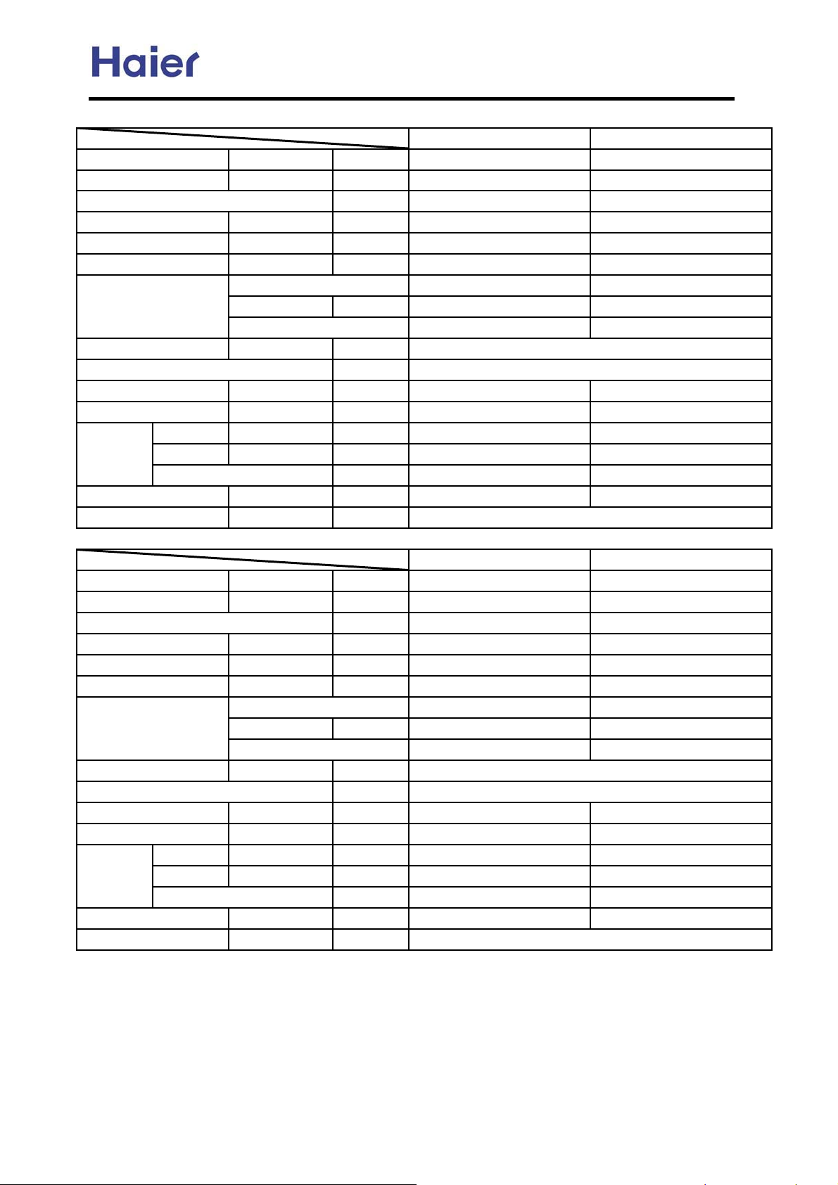
Installation state: the unit should be placed on the flat floor or be mounted in horizontal direction.
Testing method:
mounting-on-wall unit: built-in-ceiling unit: duct unit without auxiliary duct:
2m
duct
0.8m
1.4m
1.4m
1m
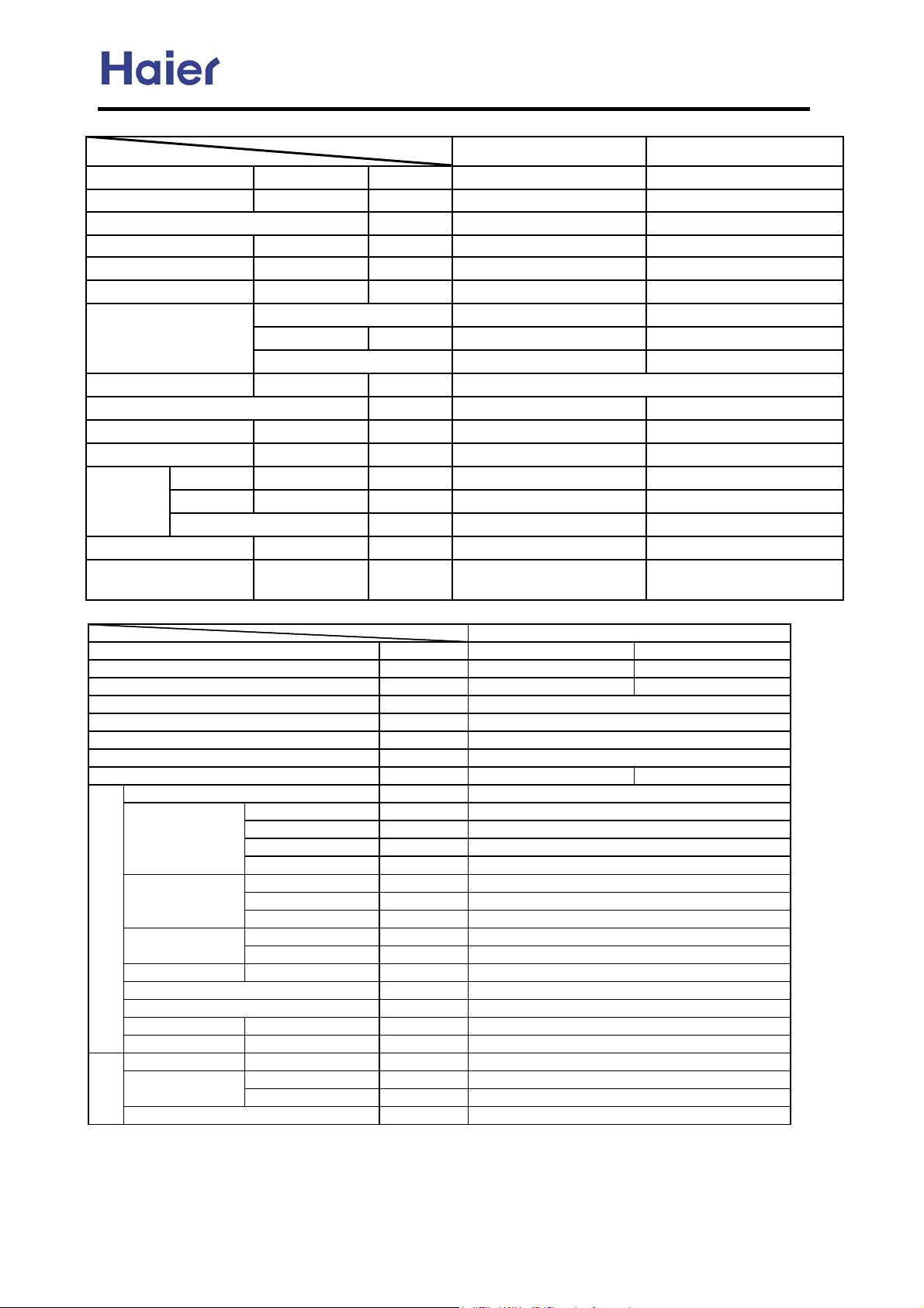
outdoor unit:
1.air outlet from side: the noise level is the average sound pressure level measured from front, left, right
directions.
2.air outlet from top: the noise level is the average sound pressure level measured from front, back, left,
right directions.
measured point:
H ( height to the ground) = (h (unit height) + 1m) /2
and, it is 1m to each side.
1m
1m
1m
h
Note: Ĵ is the real
time analyser position
1m
-13-
Commercial Air Conditioner Model: AU242FHBIA,
AU482FIBIA, AU48NFIBJA
3. Safety precaution
Carefully read the following information in order to operate the airconditioner correctly.
Below are listed three kinds of Safety Cautions and Suggestions.
WARNING!
CAUTION!
INSTRUCTIONS: These information can ensure the correct operation of the machine.
Be sure to conform with the following important Safety Cautions.
The Safety Cautions should be at hand so that they can be checked at any time when needed.
If the conditioner is transferred to the new user, this manual should be as well transferred to the new user.
Incorrect operations may result in severe consequences of death or serious injuries.
Incorrect operations may result in injuries or machine damages; in some cases may
cause serious consequences.
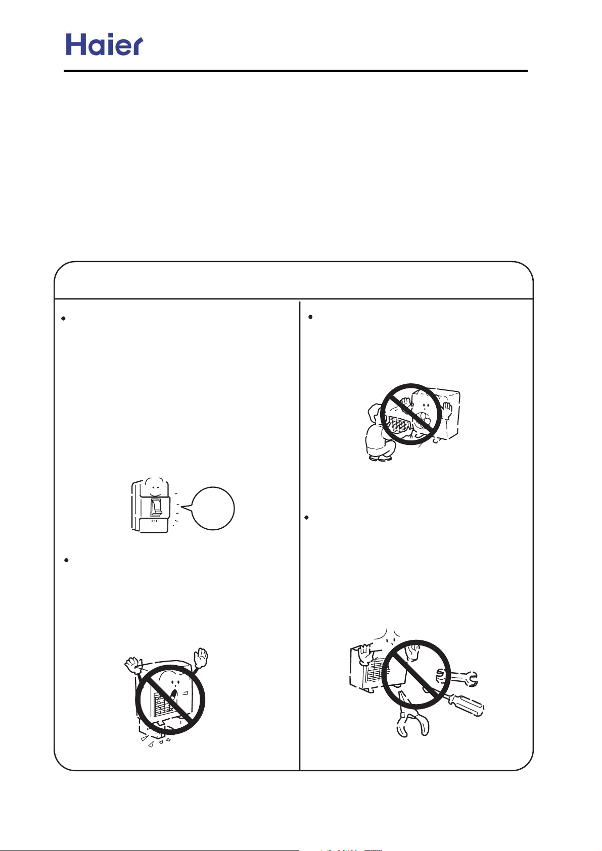
WARNING!
If any abnormal phenomena is found
(e. g.smell of firing), please cut off the
power supply immediately, and contact
the dealer to find out the handling
method.
In such case, to continue using the
conditioner will damage the conditioner,
and may cause electrical shock or fire
hazard.
Don't dismantle the outlet of the
outdoor unit.
The exposed fan is very dangerous
which may harm human beings.
switch
off
After the unit being used for a long time,
the base should be checked for any
damages.
If the damaged base is not repaired, the
unit may fall down and cause accidents.
When the unit needs maintenance and
repairment, please call dealer to handle it.
Incorrect maintenance and repairment
may cause water leak, electrical shock
and fire hazard.
-14-
Commercial Air Conditioner Model: AU242FHBIA,
AU482FIBIA, AU48NFIBJA
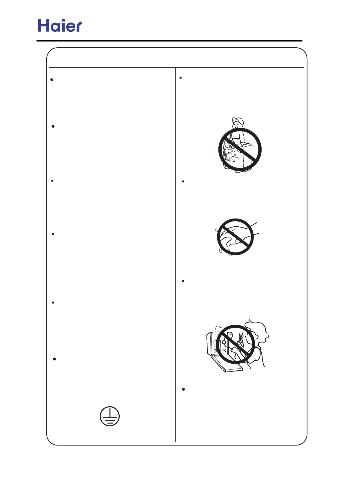
WARNING!
Installed electrical-leaking circuit
breaker.
It easily cause electrical shock without
circuit breaker.
Air-conditioner can't be installed in
the environment with inflammable
gases because the inflammable gases
near to air-conditioner may cause fire
hazard.
Please let the dealer be responsible for
installing the conditioner.
Incorrect installation may cause water
leak, electrical shock and fire hazard.
Call the dealer to take measures to
prevent the refrigerant from leaking.
Nothing or nobody is permitted to
placed on or stand on outdoor unit.
The falling of goods and people may
cause accidents.
Don't operate the air-conditioner with
damp hands.
Otherwise will be shocked.
If conditioner is installed in a small
room be sure to take every measure in
order to prevent suffocation accident
even in case of refrigerant leakage.
When conditioner is removed or
reinstalled, dealer should be responsible
for them.
Incorrect installation may cause water
leaking, electrical shock and fire hazard.
Connect earthing wire.
Earthing wire should not be connected to the gas pipe, water pipe,
lightning rod or phone line, in-correct
earthing may cause shock.
Only use correctly-typed fuse.
May not use wire or any other materials
replacing fuse, other-wise may cause
faults or fire accidents.
Use discharge pipe correctly to ensure
efficient discharge.
Incorrect pipe use may cause water
leaking.
Earthing
-15-
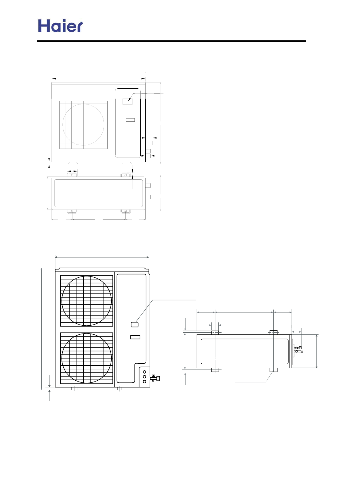
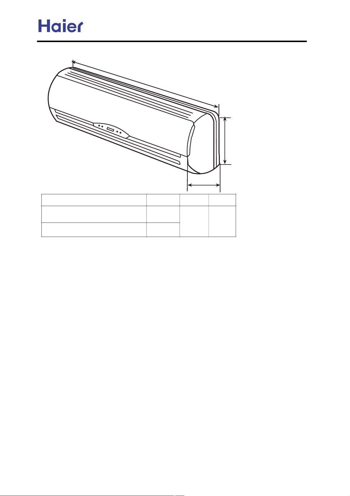
4. Net dimension
AU242FHBHA
948
Commercial Air Conditioner Model: AU242FHBIA,
AU482FIBIA, AU48NFIBJA
Power wiring terminal
840
70
25
340
AU48*
184
70
580
948
55
18
184
380
Power wiring Terminal
184 184
580
1250
25
18
380
18
-16-
70
55
340
Screw Hole
(4xM10)
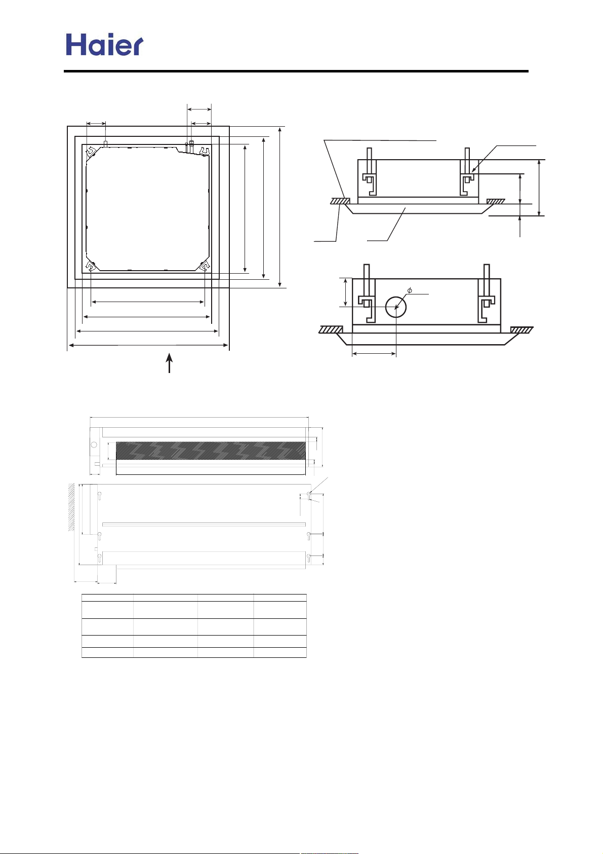
AB** Cassette unit:
B9
LXIQTIOM VQVM
:;9
A9
OIY VQVMRQW[QL VQVM
Commercial Air Conditioner Model: AU242FHBIA,
AU482FIBIA, AU48NFIBJA
U\MXRIVML LQYZITKM JMZ]MMT ZPM KMQRQTO
ITL ZPM VITMRC ;>SS
Y[YVMTYQUT PURLMX
:>9SS
<;9SS
><>SS 7JMZ]MMT Y[YVMTYQUT VURMY8
>@9SS 7QTLUUX [TQZ LQSMTYQUT8
?>9SS 7KMQRQTO UVMTQTO LQSMTYQUT8
@99SS 7VITMR LQSMTYQUT8
GFEH D
AE** Ceiling concealed unit
100
54
240
C
>@9SS 7QTLUUX [TQZ LQSMTYQUT8
?>9SS 7KMQRQTO UVMTQTO LQSMTYQUT8
@99SS 7VITMR LQSMTYQUT8
KMQRQTO
:A9
VITMR
B>
?9SS
NXMYP IQX PURM
:=9
GFEH D
b
25
225
a
25
10
R
R
5
30
29(5
unit model
AE072FCBKA
AE092FCBKA
AE122FCBKA
AE142FCBKA
AE182FCBKA
AE242FCBKA
55
93
615
704
858
990
a
b
650
800
1020
1350
c
452
452
452
452
-17-
AS** series
Commercial Air Conditioner Model: AU242FHBIA,
AU482FIBIA, AU48NFIBJA
O
:=DAI
P
Q
FH@AE
AS072FCBHA AS092FCBHA
AS122FCBHA
AS142FCBHA AS182FCBHA
=
462
6/5
>
/32
?
.64
-18-
Commercial Air Conditioner Model: AU242FHBIA,
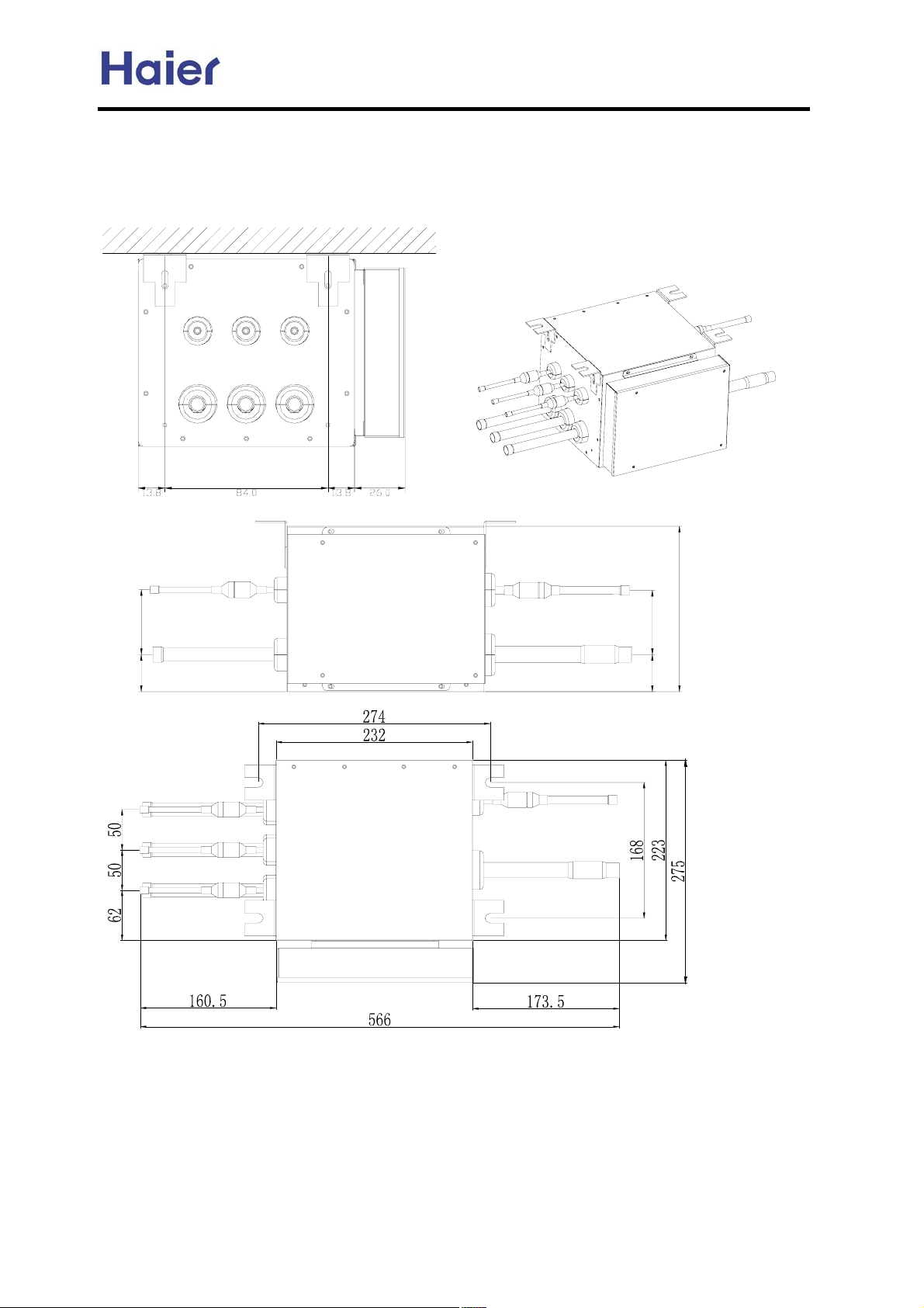
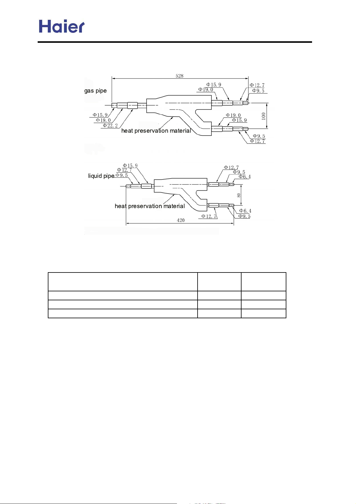
Dimensions for MP2A, MP3A:
Installation on the horizontal ceiling:
horizontal ceiling
AU482FIBIA, AU48NFIBJA
-19-
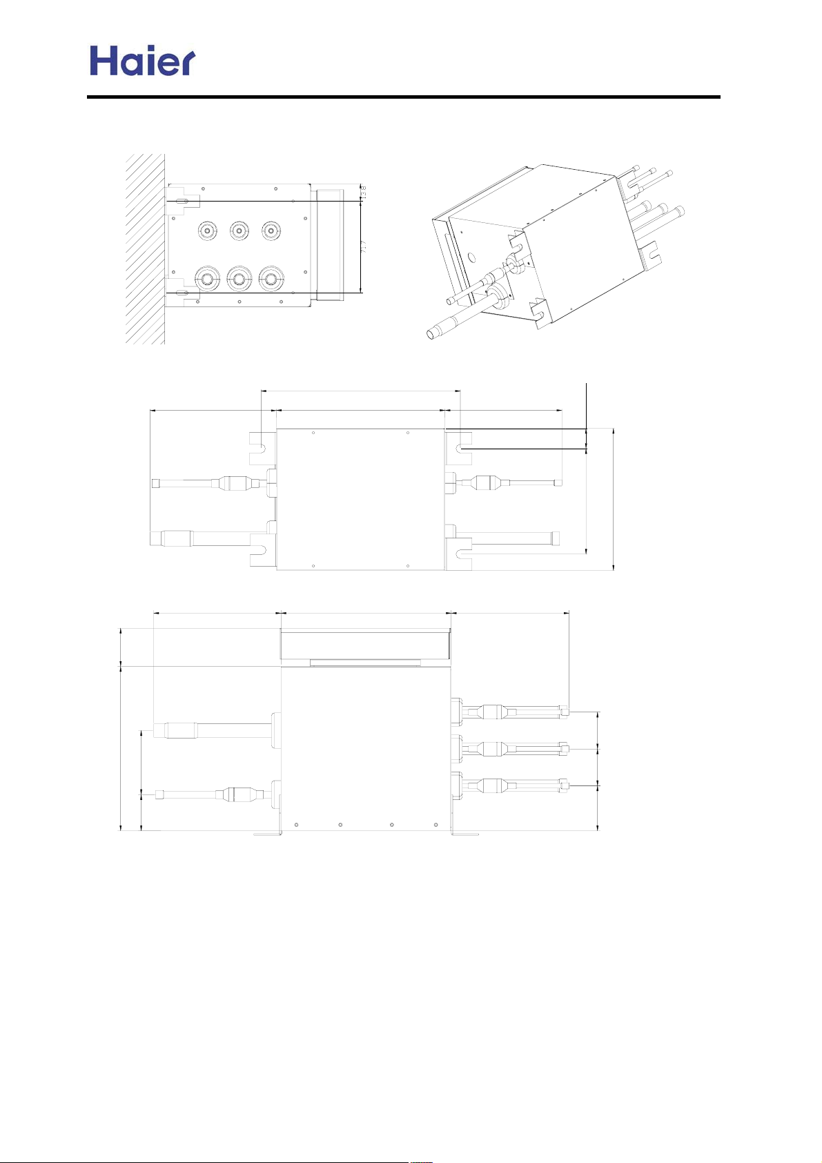
Installation on the vertical wall (adjust the installation position by fixing holder):
vertical wall
Commercial Air Conditioner Model: AU242FHBIA,
AU482FIBIA, AU48NFIBJA
-20-
Commercial Air Conditioner Model: AU242FHBIA,
5. Installation Instructions
5.1 Piping dimension chart
AU482FIBIA, AU48NFIBJA
model
liquid pipe gas pipe
mm inch mm inch
AU24 9.52 3/8" 15.88 5/8"
AU48 9.52 3/8" 19.05 3/4"
AB09 6.35 1/4" 12.7 1/2"
AB14 6.35 1/4" 12.7 1/2"
AB18 6.35 1/4" 12.7 1/2"
AE07 6.35 1/4" 9.52 3/8"
AE09 6.35 1/4" 9.52 3/8"
AE12 6.35 1/4" 12.7 1/2"
AE14 6.35 1/4" 12.7 1/2"
AE18 9.52 3/8" 15.88 5/8"
AE24 9.52 3/8" 15.88 5/8"
AS07 6.35 1/4" 12.7 1/2"
AS09 6.35 1/4" 12.7 1/2"
AS12 6.35 1/4" 12.7 1/2"
AS14 6.35 1/4" 12.7 1/2"
AS18 6.35 1/4" 12.7 1/2"
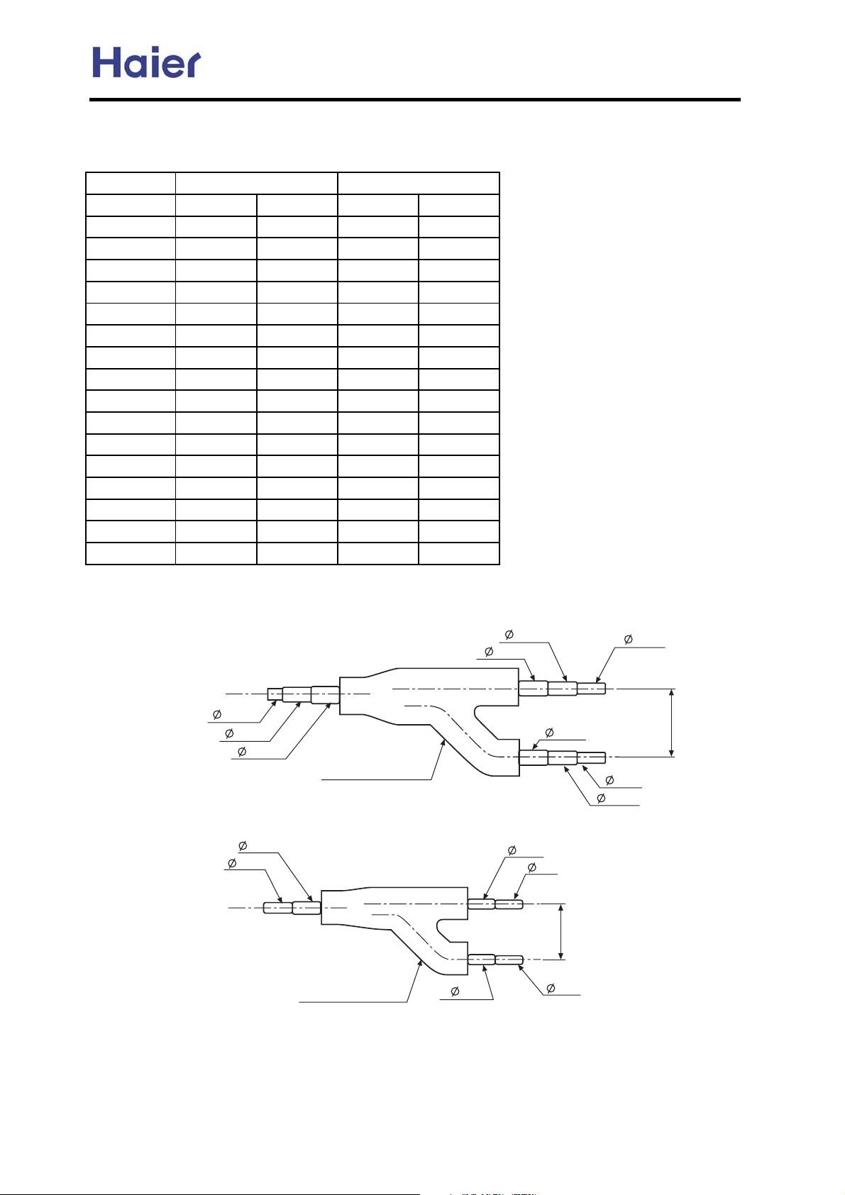
5.2 Y-shape manifold pipe
model: FQG-B120
<gas side>
9.52
12.7
15.88
<liquid side>
9.52
6.35
heat preservation
material
heat preservation
material
12.7
15.9
12.7
12.7
9.52
15.88
75
9.52
9.52
75
9.52
12.7
Dimension is the out diameter connecting to the tubing.
-21-
FQG-B180
g
Commercial Air Conditioner Model: AU242FHBIA,
AU482FIBIA, AU48NFIBJA
Refrigerant pipes between manifold pipes
Total refrigerating amount of indoor unit
Gas side Liquid side
roup after the manifold pipe
Less than 38220Btu/h 15.9 9.52
38220~61157Btu/h 19.05 9.52
61157~126137Btu/h 25.4 12.7
Note: 1. Y-shape manifold pipe can be placed in horizontal or vertical
direction
2. The manifold pipes must be welded with hard-solder
3. Pay attention to cut off the unnecessary part from its middle
parts of each joint, and to remove burr.
-22-
Commercial Air Conditioner Model: AU242FHBIA,
AU482FIBIA, AU48NFIBJA
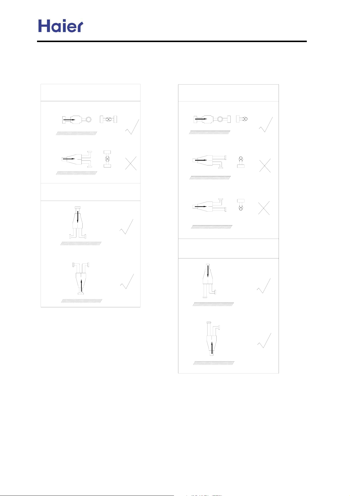
In the file, the figure marked with "Ĝ" is permitted, and the figure marked with "h" is prohibited.
You can confirm the position according to the actual condition.
The refrigerant flow direction is always from the collective side to the divided side.
horizontal
vertical
floor surface
floor surface
floor surface
horizontal
floor surface
floor surface
floor surface
vertical
floor surface
floor surface
floor surface
-23-
Commercial Air Conditioner Model: AU242FHBIA,
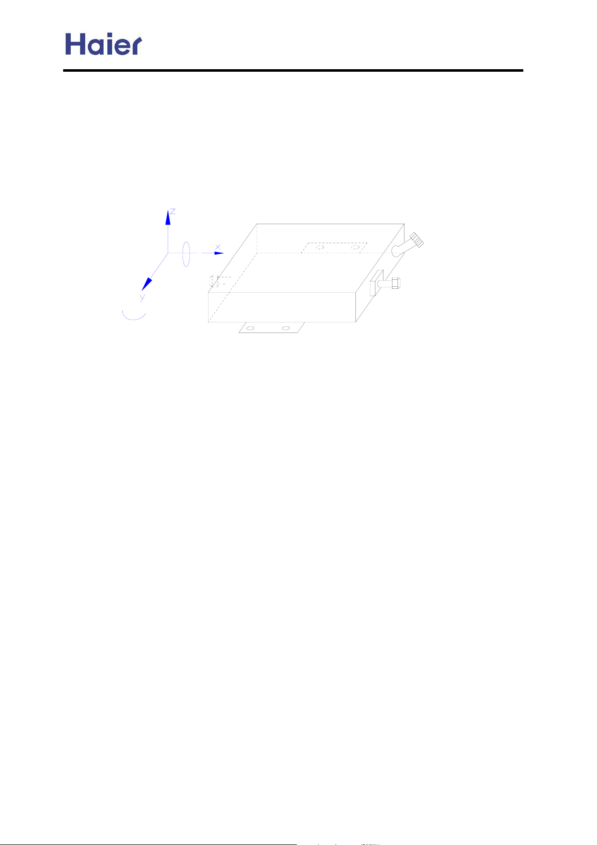
5.3 Instructions for the Electrical Expansion Valve Boxes
The E.E.V.B. general information for the C-MRV and H-MRV indoor units.
1. Installation position
AU482FIBIA, AU48NFIBJA
0°
360°
180°
Z: vertical direction
X, Y: horizontal direction
2. Installation place
The box should be installed where the place:
a. do not have vibrations;
b. easy to piping with the indoor and the outdoor unit, and the distance from the box to the indoor unit
should not exceed a certain value;
c. do not have a heat or steam source nearby;
d. should be sunless and be dry;
e. should be well ventilated and rainproof;
0°
wiring connector
liquid pipe in/out
f. do not have a strict noise restriction, because when working the box may make some noise;
-24-
Commercial Air Conditioner Model: AU242FHBIA,
AU482FIBIA, AU48NFIBJA
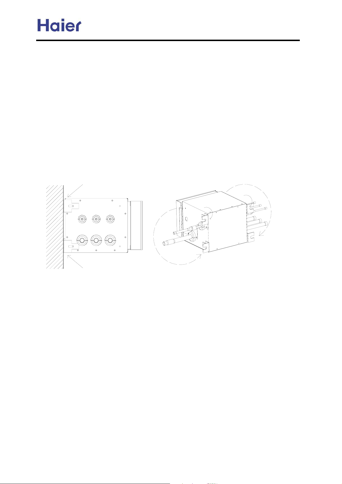
5.4 MP2A, MP3A Installation Requirement
1. Cautions
1.1 The place should be strong enough to support this equipment, no vibrantion;
1.2 The place where is convenient to install the indoor unit, outdoor unit and the refrigerant pipe, and
the length of the pipe is in the permitted range;
1.3 No heat source and gas source nearby;
1.4 The place has enough space for installation and maintenance;
1.5 Donpt installation in the place in the state of high temperature and high humidity for a long time;
1.6 The place with good ventilation, no direct sunshine and rain;
1.7 Donpt install the unit near the bedroom because of the refrigerant flow noise;
Please refer to the cautions and warnings in the operation manual about the other safety cautions.
2. Installation Method
2.1 MP2A, MP3A can be installed on the horizontal ceiling or the vertical wall by adjusting the fixing
holder. The maintenance plate should be installed on the place easy to maintain and near the place,
there should be checking hole with 600mm*600mm (adjust the fixing holder as below figure).
vertical wall
2.2 The equipment has been dealt with the EPS heat insulation material, so the drainage pipe needs
not any other treatments.
2.3 The pipe connected to indoor is led from the branch pipe of the equipment. The gas pipe
diameter can realize to match with different diameters by the changing pipe according to the
indoor pipe diameter request.
2.4 In installation, the equipment gradient should be in the range of 5¤, or it may cause electronic
expansion valve body in the equipment leakage or the other bad control failure.
2.5 Bolt, screw cap and gasket to fix the equipment will not be supplied by factory.
3. Wiring Connection
3.1 The wire and refrigerant pipe must be connected to the corresponding place (refer to marks on
the equipment and the terminal block as 1,2,3).
3.2 Wiring diagram is sticked on the back of cover plate, and the wiring must be performed
according to the wiring diagram, or the control will be bad or indoor and the equipment will be
damaged.
3.3 After wiring, the wires must be fixed with the wire clip firmly, in case that the electric control parts
are damaged or occurs person injury.
-25-
Commercial Air Conditioner Model: AU242FHBIA,
AU482FIBIA, AU48NFIBJA
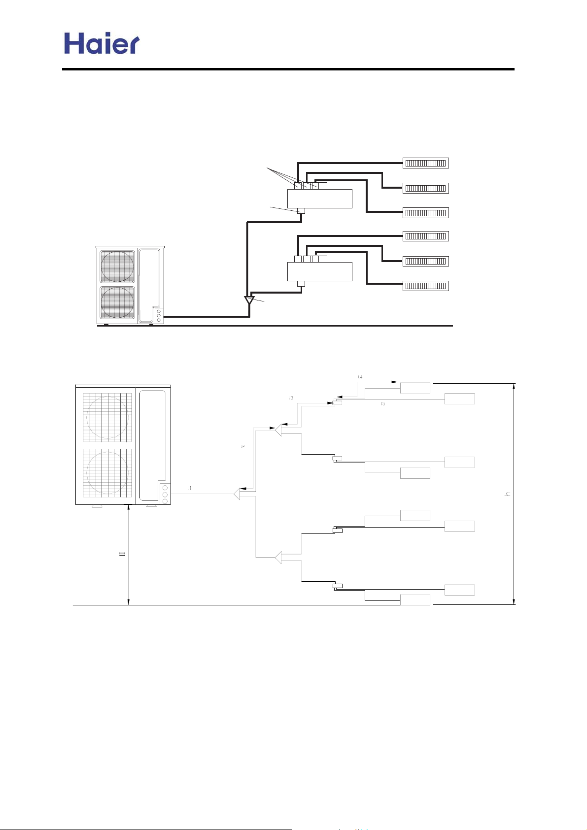
5.5 Connecting figure:
670 ;9E := LJ=< >FI KMF AE<FFI LEAKJ- GC=9J= ;FE>AID K@= 670 HL9EKAKO 9;;FI<AE? KF K@= 9;KL9C AE<FFI LEAKJ/
671 ;9E := LJ=< >FI K@I== AE<FFI LEAKJ- GC=9J= ;FE>AID K@= 671 HL9EKAKO 9;;FI<AE? KF K@= 9;KL9C AE<FFI LEAKJ/
5EJK9CC9KAFE D=K@F< AJ :=CFM- M@A;@ FECO K9B=J 671 9J 9E =N9DGC=/ 7C=9J= G9O 9KK=EKAFE K@9K K@= ?9J GAG=J
AEJK9CC9KAFE AJ 9J K@= J9D= 9J K@= ;FE<AKAFE MAK@FLK 670+671,/
AE<FFI CAHLA< GAG=
FLK<FFI CAHLA< GAG=
8.J@9G= D9EA>FC< GAG=
Piping length and drop between units
Haier
QRP
QRP
AE<FFI 2
AE<FFI 3
AE<FFI 4
AE<FFI 20
AE<FFI 30
AE<FFI 40
+
-26-
Commercial Air Conditioner Model: AU242FHBIA,
AU482FIBIA, AU48NFIBJA
1) When connected with 8 units,indoor units refer to <admissible combination examples>
2) Total length=l1+l2*2+l3*4+l4*4+l5*4<=100m
3) Max. piping length =(l1+l2+l3+l5)<=70m
4) Max. piping length between the indoor unit and the first branch pipe<=30m
5) Max. drop between outdoor unit and indoor unit: H<=30m(indoor above
outdoor);H<=20m(indoor below outdoor)
6) Max. drop between the two indoor units : h<=10m
7) Expansion valve is less than 15m to its corresponding indoor unit
8) Only wall mounted types are connected with expansion valves.
9) The expansion valves of different indoor models are different.
10)The first branch pipe must use FQG-180,the others use less than it.
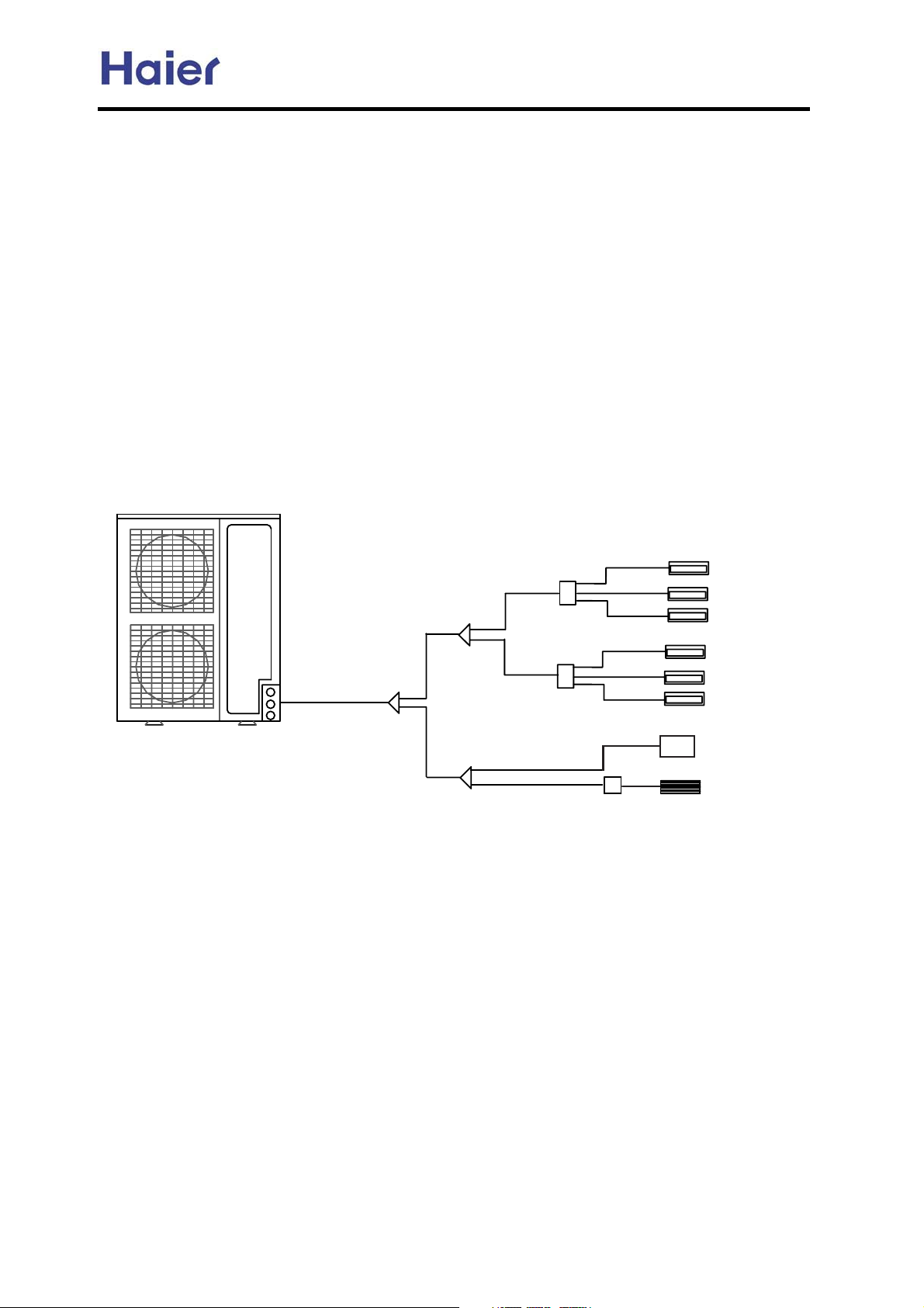
Combination example:
8 by 1:
Haier
AE07
AE07
MP3A
MP3A
EEV
AE07
AE07
AE07
AE07
AB09
AS07
Note:
1.AU24 can connect with max. 5 indoor units, and AU48 can connect with max. 8 indoor units, but pay
attention that the total indoor capacity can not exceed 130% of outdoor cooling capacity.
2.
The ceiling concealed unit must connect with the outdoor unit through the MP2A or MP3A; the wall mounted
unit must connect with the outdoor unit through the exterior EEV box; while for the cassette unit, because it has
the built-in EEV, so it need not anything and it can connect to outdoor directly.
-27-
Commercial Air Conditioner Model: AU242FHBIA,
AU482FIBIA, AU48NFIBJA
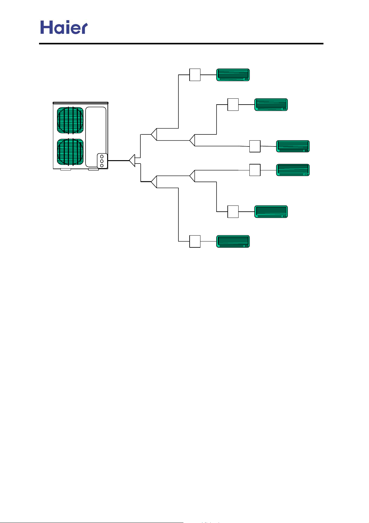
6 by one
AU48-
AS09 (or other 9000BTU units)
AS09 (or other 9000BTU units)
Haier
AS09 (or other 9000BTU units)
AS09 (or other 9000BTU units)
AS09 (or other 9000BTU units)
EEV
AS09 (or other 9000BTU units)
-28-
Commercial Air Conditioner Model: AU242FHBIA,
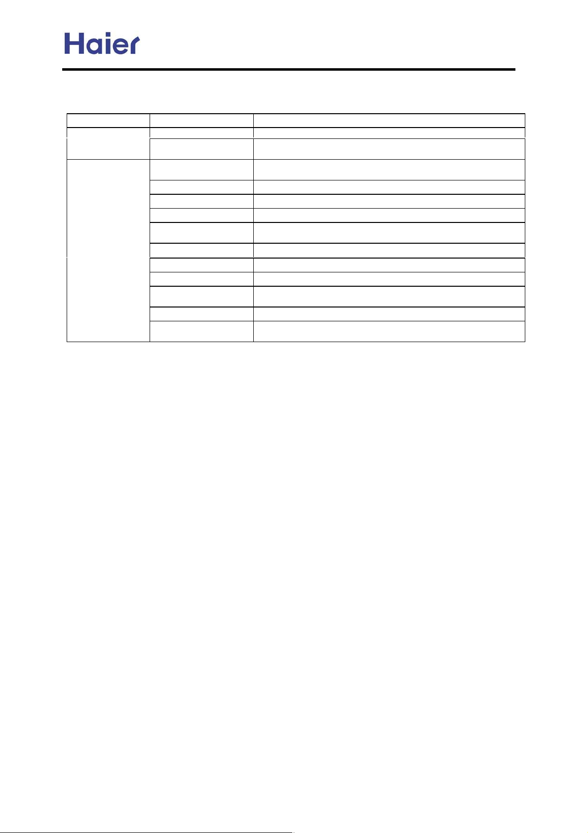
5.6 The Order of Installation Work
AU482FIBIA, AU48NFIBJA
Item
Before installation Work division -to ascertain the person responsible for installation of pipes and wiring
Work
Installation of indoor and
Work Main points
Make installation
diagram
outdoor unit
Refrigerant pipe work -Pay attention to dry, clean and seal
Drain pipe work -Slant downward
Heat insulation work -No gaps in the joint of heat insulation material
Wiring work (control
wire, power cord)
Set every set switch -Should be complied with control wiring system diagram
Airtight test -Close all the gas, liquid valves
Vacuum drying -Should the vacuum pump that can reach 200Pa vacuity
Additional refrigerant -Write down the additional refrigerant amount on the outdoor unit body
Test run adjustment -Do test run to indoor unit one by one to verify if there is wrong pipes
Training of use and
maintenance
-to ascertain the pipe installation dimension and position of electronic
expansion valve, to make control wiring system diagram
-to prevent the ventilation from short circuit and guarantee repair space
-Choose the proper wire and cord
and record table
-Explain to user, simultaneously provide all the documents
The above work order is general knowledge, they may be changed to be complied with the
specific work site.
5.7 Attentive matters of safety
Before installing, do read this [Attentive matters of safety] carefully to guarantee the
proper installation.
The below attentive matters are divided into [warning] and [note] two parts. When the
wrong installation occur, it is very possible death and severe injury and other serious
accidents will happen. For those items are listed in [warning] part. But even the items
listed in [note] part can also cause serious accidents. Above all, both the two parts are
very important contents related to safety, so they must be obeyed.
After installation, do test run to verify everything is normal, after that please explains the
use method and maintenance method to the user according to the operation manual.
Additionally, give the installation manual together with operation manual to the user and
ask them to keep them properly.
Warning
The distributing shop, where you bought the air conditioner, or the specified shops shall
do the installation work. If you do the installation work by yourself, the improper
installation will cause water leakage, electric shock fire and other accidents.
The installation work shall be in line with what the installation manual specified. If
installation is not proper, water leakage, electric shock, fire and other accidents will
occur.
Install the air conditioner to a place where can definitely stand its weight. Places not firm
enough will cause drop down of unit resulting in body hurt.
The installation work shall be preventive to typhoon and earthquake. If the installation
-29-

Commercial Air Conditioner Model: AU242FHBIA,
AU482FIBIA, AU48NFIBJA
work is not met with the requirements, overturn of the unit will occur resulting in
accidents.
The wiring work shall be done by a qualified person and referred to the “technical
standard of electric equipment”, “indoor wiring regulation” and what the manual
specified. Do use special circuit. If the capacity of the circuit is not enough or bad work,
electric shock, fire and other accidents will happen.
Using the specified cable to do wiring work and connecting firmly and properly. Fix the
connecting part of the terminals to prevent it from the external force. Improper
connection and fixing will cause heating and fire etc. accidents.
Wiring shall be kept in correct shape avoiding extrusion. After installation, the electric
box cover and the external panel shall not nip the wire. Improper installation will cause
heating and fire etc. accidents.
When setting or moving the air conditioner do not let the air and things alike get into the
refrigeration system except the specified refrigerant. If air and other things enter,abnormal
high pressure will occur, which easily cause break and body injuries etc.
When installing, do use the accessories or specified parts. If not using the parts specified
by our company, water leakage, electric shock, fire and refrigerant leakage will occur.
Do not lead the drainpipe to drain where the sulfur gas may be involved. Otherwise, the
poisonous gas will enter into the indoor.
During installation, if refrigerant leakage occurs, do the ventilation work immediately. As
soon as the refrigerant gas meets fire, poisonous gas will be produce. If the refrigerant gas
enters into room and meet the air blowing heater, heater or stove etc. fire source, the
poisonous gas may be produced. After installation, confirm there is no leakage of
refrigerant.
Do not install the unit in a place where the combustible gas may be leaked. In any case
the combustible gas leaks and accumulated around the unit, fire accident will occur.
Do heat insulation work to the refrigerant gas pipes and liquid pipes to reach the purpose
of heat preservation. If the heat insulation measure is not sufficient, water generated by
condensing dew will drip leading to wet the floor and indoor articles.
Do not damage the power line or change it arbitrarily to avoid occurrence of fire or
electric shock.
Do not extend the power line or using other electric appliance in the same power
receptacle to avoid fire or electric shock.
Note
Do grounding work. Do not connect the grounding wire to gas pipe, tap, lighting rod or
telephone line. Improper grounding will cause electric shock.
In some places the electric leakage breaker shall be installed. If do not install the breaker,
electric shock may occur.
After installation, power on to do electric leakage detecting test.
-30-
 Loading...