

Haier AU422FIAHA, AU242FHAHA, AU242FHBHA, AU482FIAHA, AU48NFIAHA Service Manual
...
Home MRV
Service Manual
2003.08
SYJS-0308

CONTENT
1. DESCRIPTION OF PRODUCTS & FEATURES
1.1 Nomenclature
1.2 Combination of indoor and outdoor
1.3 Models of indoor and outdoor units
1.4 Character of products
1.5 Cooling and heating capacity curves
2. SPECIFICATIONS
3. MECHANICAL DATA
3.1 Controllers/Instruction/Dimension
3.2 Refrigerant diagram
4. ELECTRICAL DATA
4.1 Wiring diagram
4.2 Circuit diagram
4.3 Resistance-Temperature character
5. NOISE LEVEL CHART
6. ELECTRICAL CONTROL FUNCTIONS
6.1 Indoor unit No. setting method
6.2 Flow chart for operation
6.3 Defrost operation flow chart
7. DIAGNOSTIC INFORMATION (TROUBLE SHOOTING)
7.1 Fault codes
7.2 Troubleshooting
7.3 Example of repair
8. INSTALLATION INSTRUCTIONS
8.1 Piping dimensions chart
8.2 Y-shape manifold pipe
8.3 Piping length and drop between the units
8.4 Combination examples
8.5 Installation dimensions
8.6 The order of Installation Work
8.7 Attentive matters of safety
8.8 Special work and main points in installation
8.9 Test of airtight quality
8.10 Charging of refrigerant
8.11 Refrigerant
8.12 Electric wiring
8.13 Unit number setting in site
8.14 Checks after the installation
9.
EXPLODED VIEWS & PART LISTS
NOTE:THE PARTS MARKED WITH*** ARE ADDED INFORMATION
1 DESCRIPTION OF PRODUCTS & FEATURES
l Indoor unit:
Model of indoor unit
A S 09 2 F M A H A
1 2 34 5 6 7 8 9 10
1 Product symbol (A stands for air conditioner)
2 Product mode (S stands for split type air conditioner)
3 , 4 Product specification (09 stands for cooling/heating capacity is 9000BTU/h)
5 Applicable voltage (2 stands for 220-240V/50Hz)
6 Product series (F stands for free combination)
7 Appearance character (M stands for 28 large arc normal air inlet grille 1232084
back frame )
8 Product type (A stands for heat pump type, refrigerant is R22)
9 Design number (H stands for inverter heat pump air conditioner)
10 Climate type (A stands for T1 climate)
Model of indoor unit
A P 18 2 F A A H A
1 2 3 4 5 6 7 8 9 10
1 Product symbol (A stands for air conditioner)
2 Product mode (P stands for packaged type air conditioner)
3 , 4 Product specification (18 stands for cooling/heating capacity is 18,000BTU)
5 Applicable voltage (2 stands for 220-240V/50Hz)
6 Product series (F stands for free combination)
7 Appearance character (A stands for appearance of inverter packaged type air
conditioner)
8 Product type (A stands for heat pump type, refrigerant is R22)
9 Design number (H stands for inverter heat pump air conditioner)
10 Climate type (A stands for T1 climate)
l Outdoor unit:
Model of outdoor unit
A U 42 2 F I A H A
1 2 3 4 5 6 7 8 9 10
1 Product symbol (A stands for air conditioner)
2 Product mode (U stands for split type air conditioner outdoor unit)
3 , 4 Product specification (42 stands for cooling/heating capacity is 42,000BTU)
5 Applicable voltage (2 stands for 220-240V/50Hz)
6 Product series (F stands for free combination)
7 Appearance character (I stands for 5HP outdoor unit)
8 Product type (A stands for heat pump type, refrigerant is R22)
9 Design number (H stands for inverter heat pump air conditioner)
10 Climate type (A stands for T1 climate)
1. Nomenclature
Equivalent power of outdoor unit
Model of outdoor unit
AU422FIAHA AU422FIAIA AU422FIBIA
Total amount of indoor units can be
connected with
Types of indoor units can be
connected with
Capacity range of indoor units
connected with each system of A,B
2. Combination of indoor and outdoor
5HP
6 sets
4 sets
3 sets
50%-130% of each system's capacity
3 sets
See Table Indoor units
4 sets
Equivalent power of outdoor unit
Model of outdoor unit
Total amount of indoor units can be
connected with
Types of indoor units can be
connected with
Capacity of indoor units can be
connected with
3HP
AU242FHAHA AU242FHBHA
3 sets 3 sets
3 sets
9000~27000BTU/h
2 sets 1 sets
See next page table Indoor units
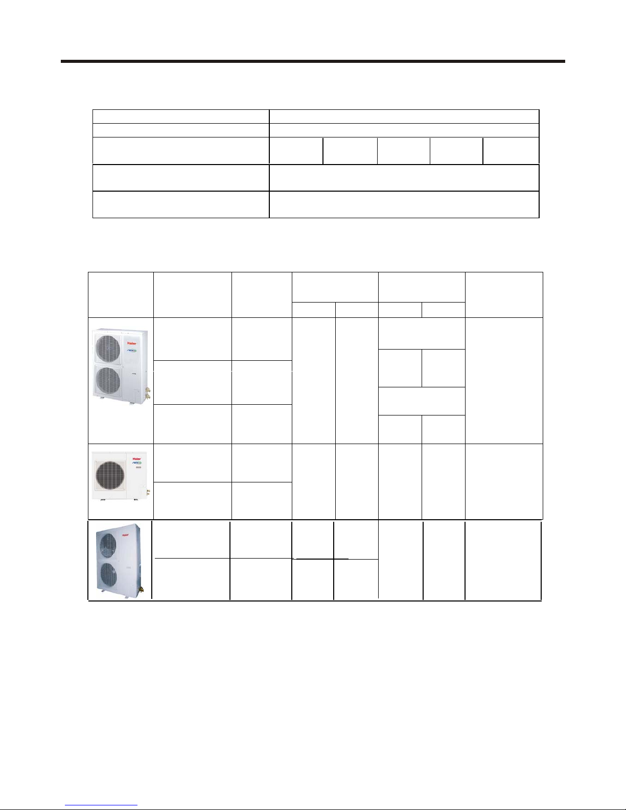
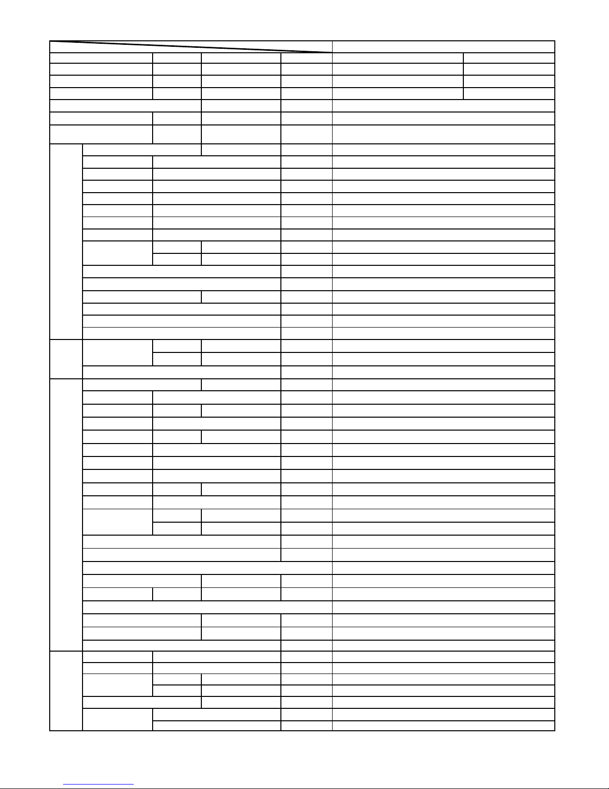
3. Models of indoor and outdoor units
Outdoor units
Capacity
(BTU/h)
Connect capacity
(HP)
Appearance Model
Refrigerant
Cooling Heating Min Max
Max. indoor
units can be
connected
Single system
AU422FIAHA R22
1.0 3.0
AU422FIAIA
R22
Two systems
(5HP)
AU422FIBIA
R407C
41000 48000
2.0 6.0
6
AU242FHAHA R22
(3HP)
AU242FHBHA R407C
24000 29000 1.0 3.0 3
AU482FIAHA R22 48000 56000
AU48NFIAHA R22 48000 56000
1.0 6.0
8
indoor units
cooling heating
AB092FCAHA R22 10000 12000
AB142FCAHA R22 14000 17000
AB092FCBHA
R407C 9000 11000
AB142FCBHA
R407C 14000 16000
AB182FCAHA R22 18000 21000
AB182FCBHA
R407C
18000 21000
AC142FCBHA
R407C 14000 16000
AC182FCBHA
R407C
18000 21000
AC182FCAHA R22 18000 21000
AE072FCAKA R22 7000 9000
AE092FCAHA R22 9000 11000
AE092FCBHA
R407C
9000 11000
AE182FCAHA R22 18000 21000
AE182FCBHA
R407C
18000 21000
AE242FCAKA R22 24000 28000
AE092FCAKA R22 9000 11000
AE122FCAKA R22 12000 14000
AE142FCAKA R22 14000 16000
AE182FCAKA R22 18000 21000
AE212FCAKA R22 21000 24000
AE112FCBIA
R407C
11000 13600
AE182FCBIA
R407C
18000 20500
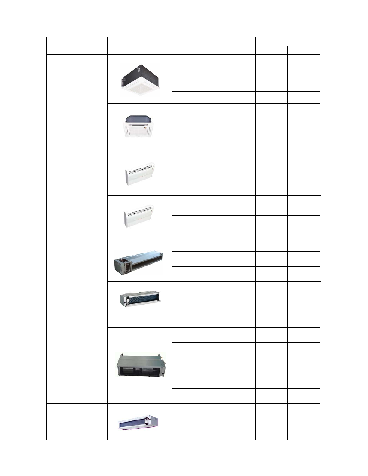
Four way cassette
Convertible
Ceiling
concealed(TES
indoor)
capacity(BTU/h)
Ceiling concealed
type appearance model refrigerant
AP182FAAHA R22 18000 21000
AP182FABHA
R407C
18000 21000
AF092FCBHA
R407C
9000 13000
AF122FCBHA
R407C
12000 17000
AS062FMAHA R22 6000 8000
AS072FMAHA R22 7000 9000
AS092FMAHA R22 10000 13000
AS092FMBHA R407C 10000 13000
AS122FMAHA R22 12000 14000
AS122FBBHA R407C 12000 14000
AS182FTAHA R22 18000 21000
AS182FTBHA R407C 18000 21000
Console
Cabinet
Wall-mounted

4. Character of Products
1) The length of horizontal refrigerant pipe can reach 70m,the total pipe length can reach
100m, the height difference between indoors unit and outdoor unit can reach 30m, the
height difference between indoor units can reach 10m.
2) 1000m super far distance communication between indoor and outdoor units, convenient
control and easy to enlarge the scale of units assembly.
3) Indoor unit can be controlled separately.
4) Equipped with computer-checking interface, conveniently for service work.
5) Far distance sending of refrigerant, and distribute refrigerant intelligently and reasonably
according to the needs of each room, high efficient and energy saving.
6) Display of automatic test of trouble.
7) Healthy negative ion generation function can refresh the air and excite the oxygen,it is optional.
8) The ceiling concealed models move the indoor electronic expansion valve out to
MP3 (electronic expansion valve box), completely avoid the flow sound of EEV,
extremely lower noise, and realize super-silence running in deed.
9) The ceiling concealed models (except AE07\AE24) all have return air box, it will be
set back return air when out of factory. When installation, bottom plate 2 can be
removed and installed on the back, consequently, return air mode has been
transferred to down return air.
10) In order to remain the best running state of indoor unit, control the refrigerant flow
by MP3 (MP2), so as to realize energy saving for every unit and the most
comfortable operation.
11) The units except for convertible model are all wired controller and remote controller
models.If you want a wired control unit or a remote control unit, please inform us ahead of
schedule.
The unit with remote controller is matched with receive display.
The unit with wired controller equipped with wired controller, can make remote operation on
wired controller with remote controller such as YR-H39, but the remote controller is
additionally purchased.
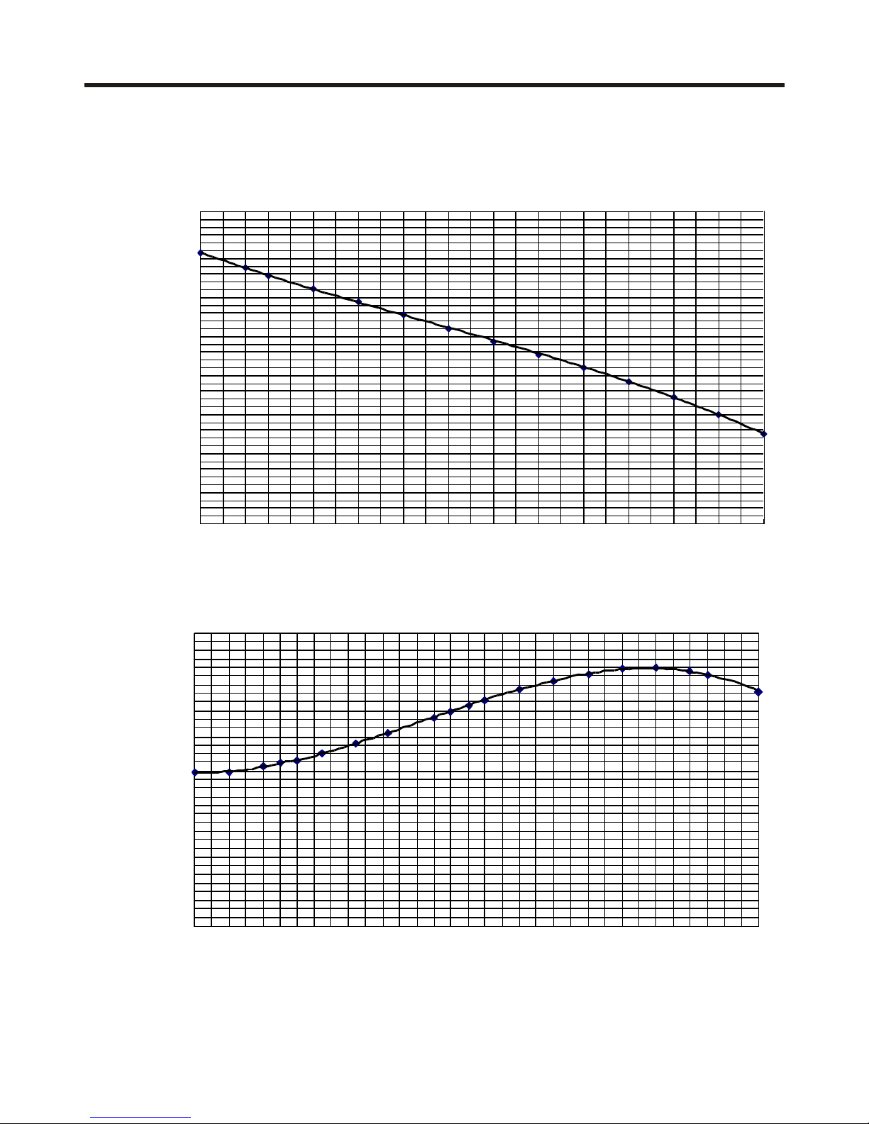
10.00
10.50
11.00
11.50
12.00
12.50
13.00
13.50
14.00
182328333843
outdoor temp.
cooling capacity(kW)
0.00
1.00
2.00
3.00
4.00
5.00
6.00
7.00
8.00
9.00
10.00
11.00
12.00
13.00
14.00
15.00
16.00
17.00
-15-13-11-9-7-5-3-11357911131517
outdoor temp.
heating capacity(kW)
5. Cooling and heating capacity curves
(AU422FIAHA / AU422FIAIA / AU422FIBIA)
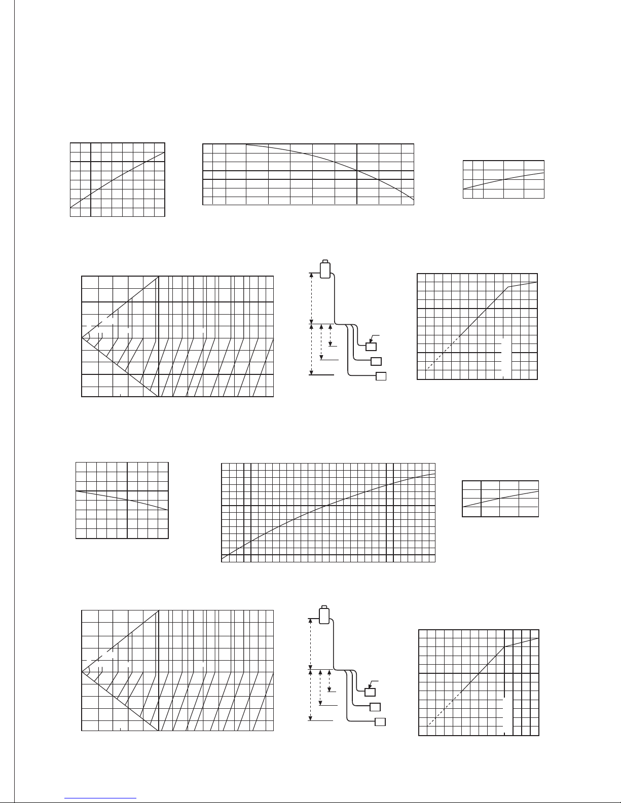
1) Calculation method
Calculation method of refrigerating capacity-Refrigerating capacity to be known = Refrigerating
capacity x (1) x (2) x (3) x (4) x (5) W
A
B
C
120
100
80
60
40
20
0
20 40 60 80 100 120 135
1.1
1.0
0.9
80 90 100 110 120
1.2
1.1
1.0
0.9
0.8
0.7
0.6
0.5
-15 -10 -5 0 5 10 15
1.2
1.1
1.0
0.9
0.8
15
20
24
120
100
80
60
40
20
0
20 40 60 80 100 120 135
A
B
C
(1) Capacity compensation value of indoor
air wet-bulb temperature condition
1.1
1.0
0.9
80 90 100 110 120
1.2
-5
1.1
1.0
0.9
0 5 10 15 20 25 30 35 40 43
Capacity compensation value of outdoor air dry-bulb
temperature condition
(3) Capacity modification value
under airflow variation rate of
indoor unit group (only for
airflow type unit)
indoor air wet-bulb temperature(*)
outdoor air dry-bulb temperature(*)
airflow variation rate
Capacity modification value
(4) Fall of refrigerant pipe of indoor and outdoor
unit, capacity compensation value of pipe length
1.2
1.1
1.0
0.9
0.8
15
20 24
(5) Capacity compensation suitable
for total capability of indoor unit
group (cooling)
Outdoor unit
Indoor unit group
capacity modification value
lo
he
la
lb
lc
ha
hchb
ho
standard capacity
L(m) Length of refrigerant
pipe (corresponding length)
L (m)
Total capacity of indoor unit group
2) Calculation method of heating capacity—Heating capacity to be known = Heating capacity ((1) x (2) x (3) x (4) x (5) x (6)) W
(1) Capacity modification under indoor
air wet-bulb temperature condition
(2) Capacity modification under outdoor air wet-bulb temperature condition
(3) Capacity modification
value under airflow variation
rate of indoor unit group
indoor air dry-bulb temperature(*)
outdoor air wet-bulb temperature(*)
(4) Fall of refrigerant pipe of indoor and outdoor unit,
capacity compensation value of pipe length
(5) Capacity compensation suitable
for total capability of indoor unit
group (heating)
Length of refrigerant pipe (corresponding length) L (m)
Outdoor unit
Indoor unit group
capacity modification value
H=ho+(the max. value of ha, hb, hc)
L=lo+(the max. value of la, lb, lc)
Total capacity of indoor unit group
standard capacity
lo
ho
he
ha
lb
le
hc
hb
10 20 30 40 50 60 70 80 90 100 110 120
25
100%
99
98
97
99
98
979695
9493929190
89
88
87
86
50
40
30
20
10
0
-30
-40
-50
-20
-10
10 20 30 40 50 60 70 80 90 100 110 120
25
100%
99
98
97
99
98
979695
9493929190
89
88
87
86
50
40
30
20
10
0
-30
-40
-50
-20
-10
AU48- Characteristics of refrigerating and heating capacity
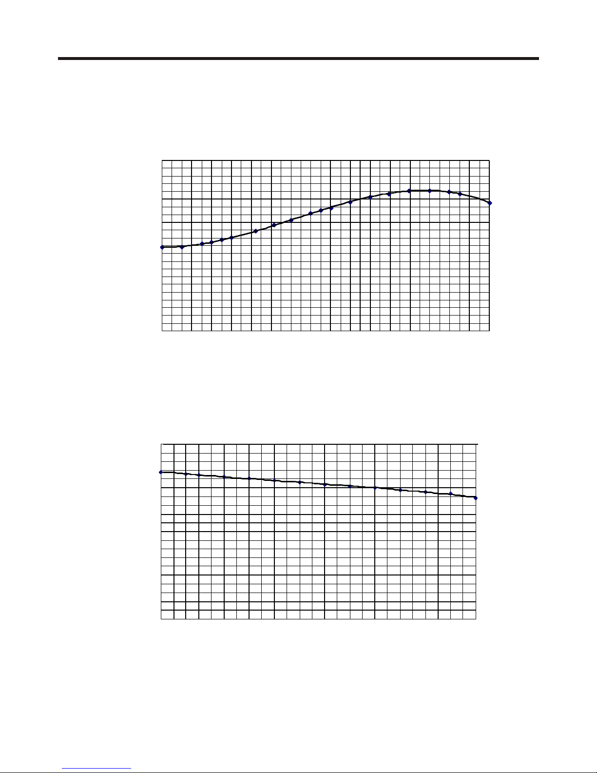
(AU242FHAHA / AU242FHBHA)
0.00
1.00
2.00
3.00
4.00
5.00
6.00
7.00
8.00
9.00
10.00
11.00
-15-13-11-9-7-5-3-11357911131517
outdoor temp.
heating capacity( kW)
0.00
1.00
2.00
3.00
4.00
5.00
6.00
7.00
8.00
9.00
10.00
182328333843
outdoor temp.
cooling capacity(kW)
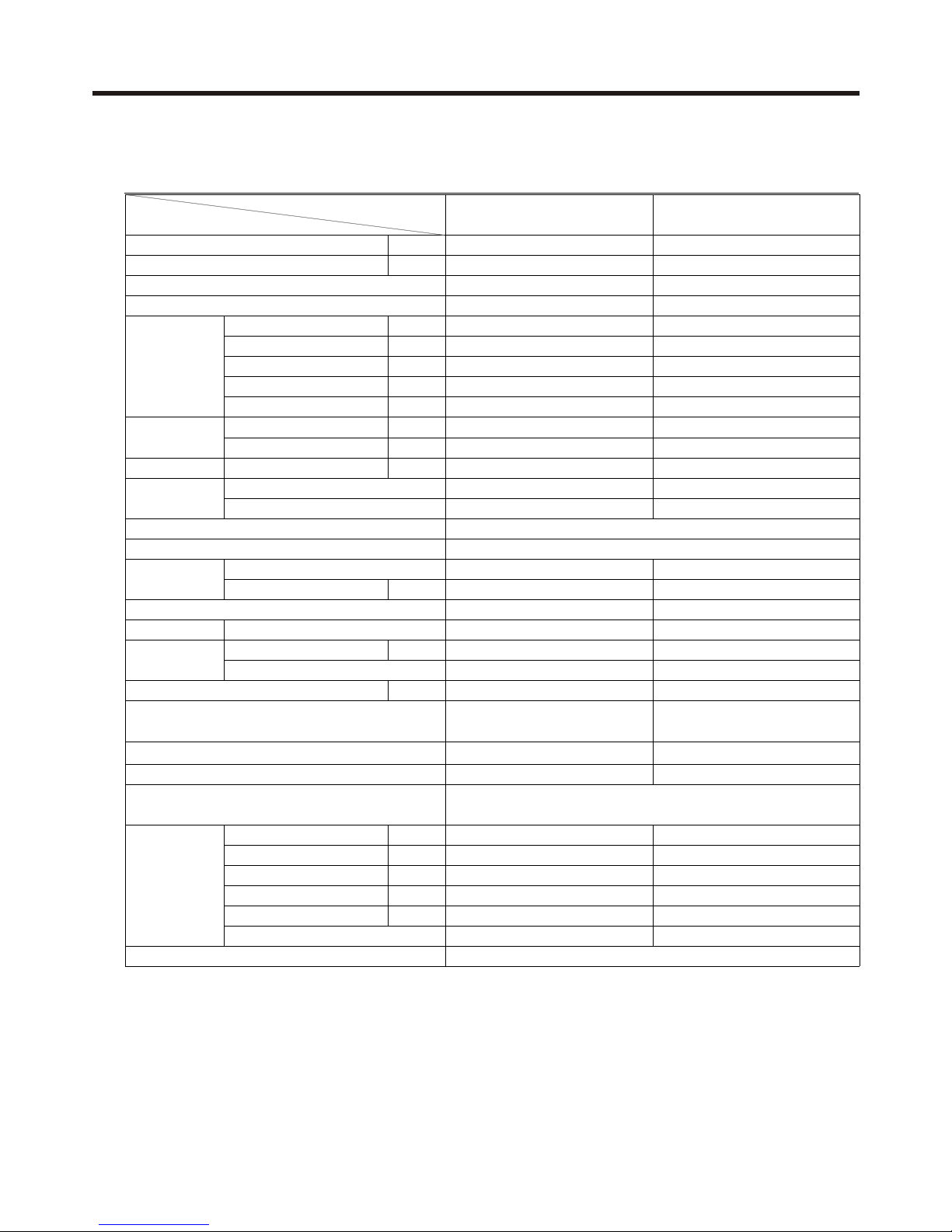
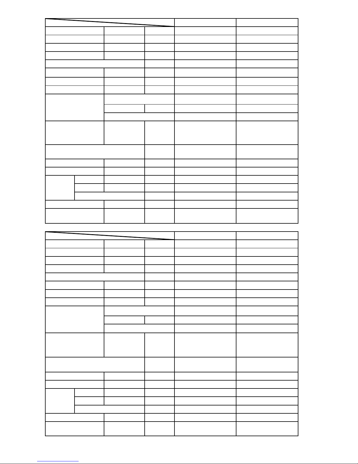
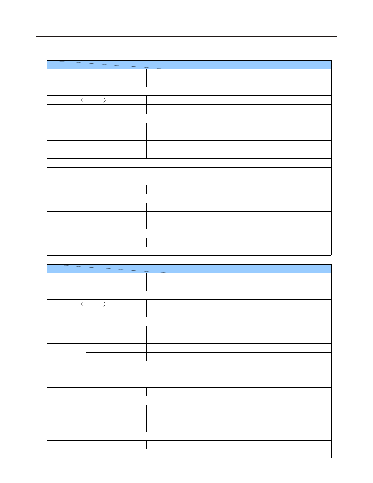
2 SPECIFICATIONS
AU422FIAHA AU422FIAIA
Btu/h
41000
41000
Btu/h
48000
48000
*1PH 220-230V 50Hz
*1PH 220-230V 50Hz (×2)
30~120Hz
30~120Hz
Cooling power W
5000(7100max)
5000(7100max)
Running current A
24(36max)
24(36max)
Heating power W
5000(7100max)
5000(7100max)
Running current A
24(36max)
24(36max)
Noise level dB(A)
59/-/ 1m long 1m distance distance
59/-/-
External mm
1250×1035×340
1250×1035×340
Package mm
1375×1050×440
1375×1050×440
Weight Net/Gross Kg
91/111
91/111
HV341A2-S12L
HV341A2-S12L
Direct start
Direct start
R22
R22
Charge g
1600×2
1600×2
Reverse cycle Reverse cycle
Fan
Screw fan x 2
Screw fan x 2
Power output W
60×2
60×2
Soft inverter
Soft inverter
m3/h
6480
6480
Rubber bracket
(compressor use)
Rubber bracket
(compressor use)
Indoor unit side
Indoor unit side
Electronic thermosta
Electronic thermosta
Liquid mm
9.52
9.52
Gas mm
15.88
15.88
*Piping length m
50(max)
50(max)
*Drop between I.U. and O.U. m
30(max)
30(max)
*Drop between I.U. and I.U. m
10(max)
10(max)
Flared
Flared
* The AU422FIAHA has one power source terminal block.
Item Model
Cooling capacity
Heating capacity
Power source
Working frequency scope
Running data
Dimension
L×W×H
Compressor
Model
Starting method
Heat exchanger Combination of wave cranny radiation fin and copper pipe
Refrigerant control method Capillary + electronic expansion valve (PMV)
Refrigerant
Type
Defrost method
Type×Number
Fan motor
Starting method
Air-flow
Anti-vibration and sound insulation devices
Control mode (remote/wired)
Indoor temperature control
Safety devices
* The indoor unit (I.U.) and the outdoor unit (O.U.) are in the same system.
* The AU422FIAIA has two power source terminal blocks. The power source can be 2×(220V, 1ph, 50Hz), or it can
be two phases of (380V, 3N, 50Hz).
Compressor internal equipped protector /Fan motor internal
equipped thermostat /Compressor internal equipped reductor
Piping
Connecting method
Accessories
Parts need in installation, controller
1). 5HP outdoor unit (R22)
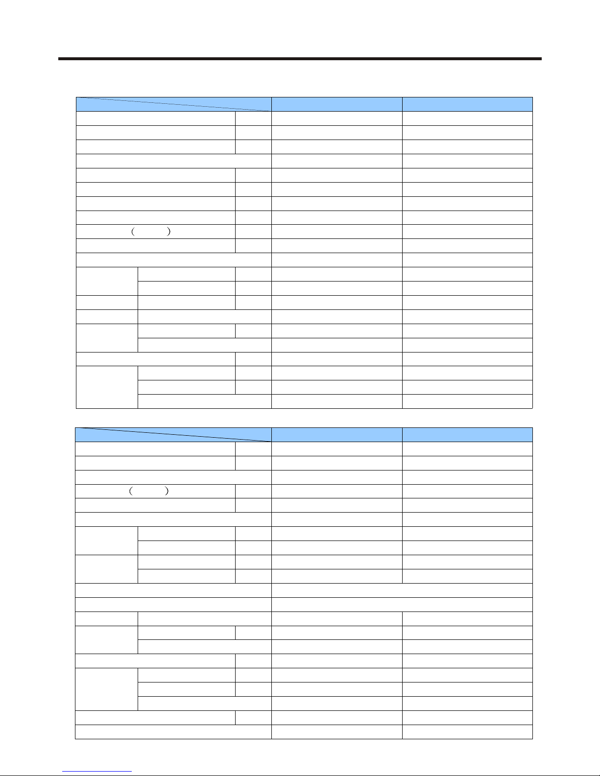
* The two indoor units (I.U.) are in the same system.
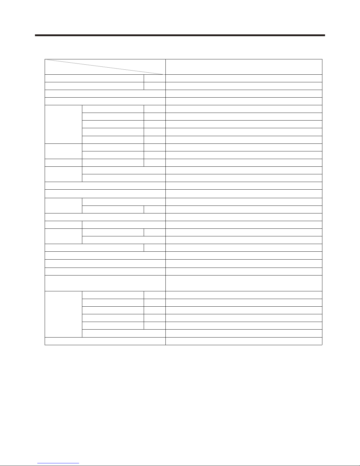
Btu/h
Btu/h
Cooling power W
Running current A
Heating power W
Running current A
Noise level dB(A)
External mm
Package mm
Weight Net/Gross Kg
Charge g
Fan
Power output W
m3/h
Liquid mm
Gas mm
*Piping length m
*Drop between I.U. and O.U. m
*Drop between I.U. and I.U. m
10(max)
Flared
Indoor unit side
Electronic thermosta
9.52
15.88
60×2
Soft inverter
6480
Rubber bracket (compressor use)
R407C
2000×2
Reverse cycle
Screw fan x 2
91/111
BG240X2CS-20KU
Direct start
41000
48000
*1PH 220-230V 50Hz (×2)
26(36max)
59/-/1250×1035×340
1375×1050×440
30~120Hz
5200(7100max)
27(36max)
5100(7100max)
AU422FIBIA
Combination of wave cranny radiation fin and copper pipe
Capillary + electronic expansion valve(PMV)
Compressor internal equipped protector /Fan motor internal
equipped thermostat /Compressor internal equipped reductor
Safety devices
Air-flow
Control mode (remote/wired)
Indoor temperature control
Anti-vibration and sound insulation devices
Heat exchanger
Refrigerant control method
Item Model
Cooling capacity
Fan motor
Starting method
Compressor
Heating capacity
Defrost method
Type×Number
Refrigerant
Running data
* The indoor unit (I.U.) and the outdoor unit (O.U.) are in the same system.
Piping
Connecting method
Accessories
* The AU422FIBIA has two power source terminal blocks. The power source can be 2×(220V, 1ph, 50Hz), or it can
be two phases of (380V, 3N, 50Hz).
Parts need in installation, controller
50(max)
30(max)
Type
Power source
Working frequency scope
Model
Starting method
Dimension
L×W×H
2). 5HP outdoor unit (R407C)
* The two indoor units (I.U.) are in the same system.
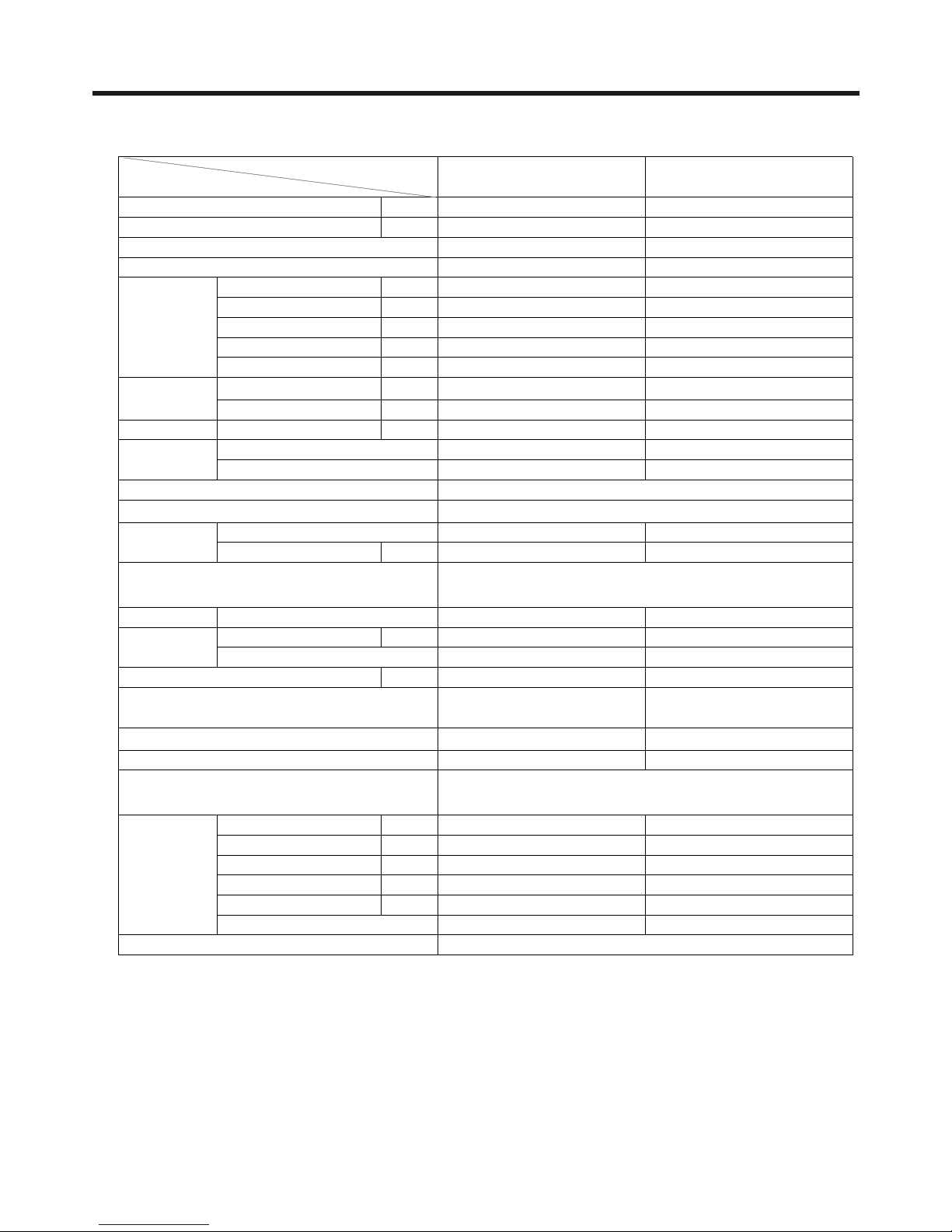
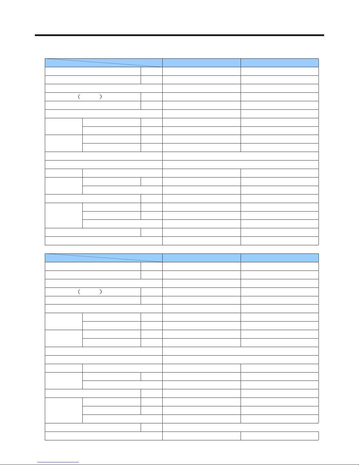
AU242FHAHA AU242FHBHA
Btu/h 24000 24000
Btu/h 28000 27000
1PH 220-230V 50Hz 1PH 220-230V 50Hz
30~120Hz 30~120Hz
Cooling power W 3100(3700max) 3200(3800max)
Running current A 15.5(18max) 18(21max)
Heating power W 3100(3700max) 3100(3800max)
Running current A 15.5(18max) 17(21max)
Noise level dB(A) 58/-/- 58/-/-
External mm 948×340×830 948×340×830
Package mm 1075×445×965 1075×445×965
Weight Net/Gross Kg 74/89 74/89
THV247FBE C-7RB267H03AA
Direct start Direct start
R22 R407C
Charge g 2200 3200
Fan Screw fan×1 Screw fan×1
Power output W 60 60
Soft inverter Soft inverter
m3/h 3240 3240
Rubber bracket
(compressor uses)
Rubber bracket
(compressor uses)
Indoor unit side Indoor unit side
Electronic thermosta Electronic thermosta
Liquid mm 9.52 9.52
Gas mm 15.88 15.88
Piping length m 50m(max) 50m(max)
Drop between I.U. and O.U.
m 30m(max) 30m(max)
Drop between I.U. and I.U.
m 10m(max) 10m(max)
Flared Flared
Parts need in installation, controller
Combination of wave cranny radiation fin and copper pipe
Capillary + electronic expansion valve
Microcomputer temperature difference type anti-icing reverse cycle
mode defrosting
Compressor internal equipped protector Fan motor internal
equipped thermostat Compressor internal equipped reductor valve
Running data
Item Model
Cooling capacity
Heating capacity
Power source
Working frequency scope
Dimension
L×W×H
Compressor
Model
Starting method
Heat exchanger
Refrigerant control method
Refrigerant
Fan motor
Type
Defrost method
Type×Number
Starting method
Air-flow
Anti-vibration and sound insulation devices
Piping
Control mode (remote/wired)
Indoor temperature control
Safety devices
Connecting method
Accessories
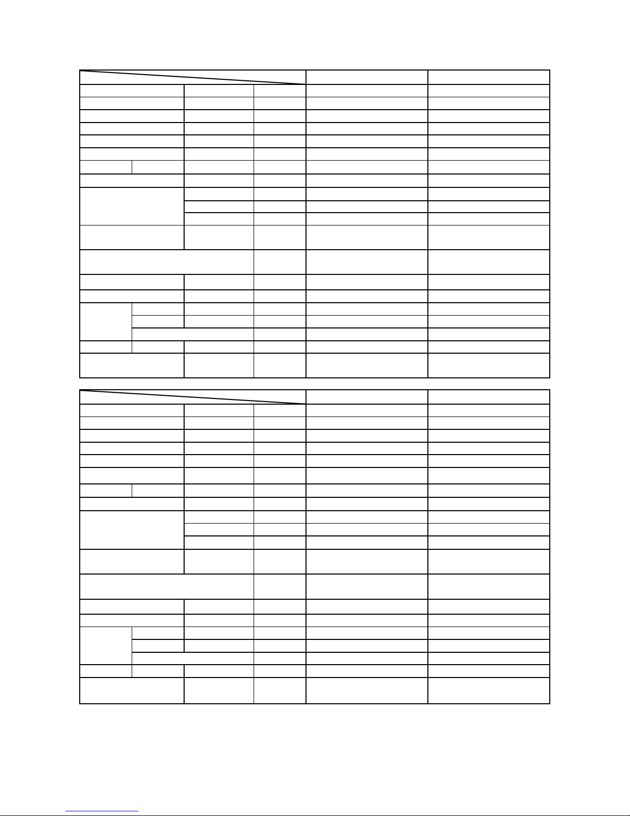
3). 3HP outdoor unit (R22 & R407C)
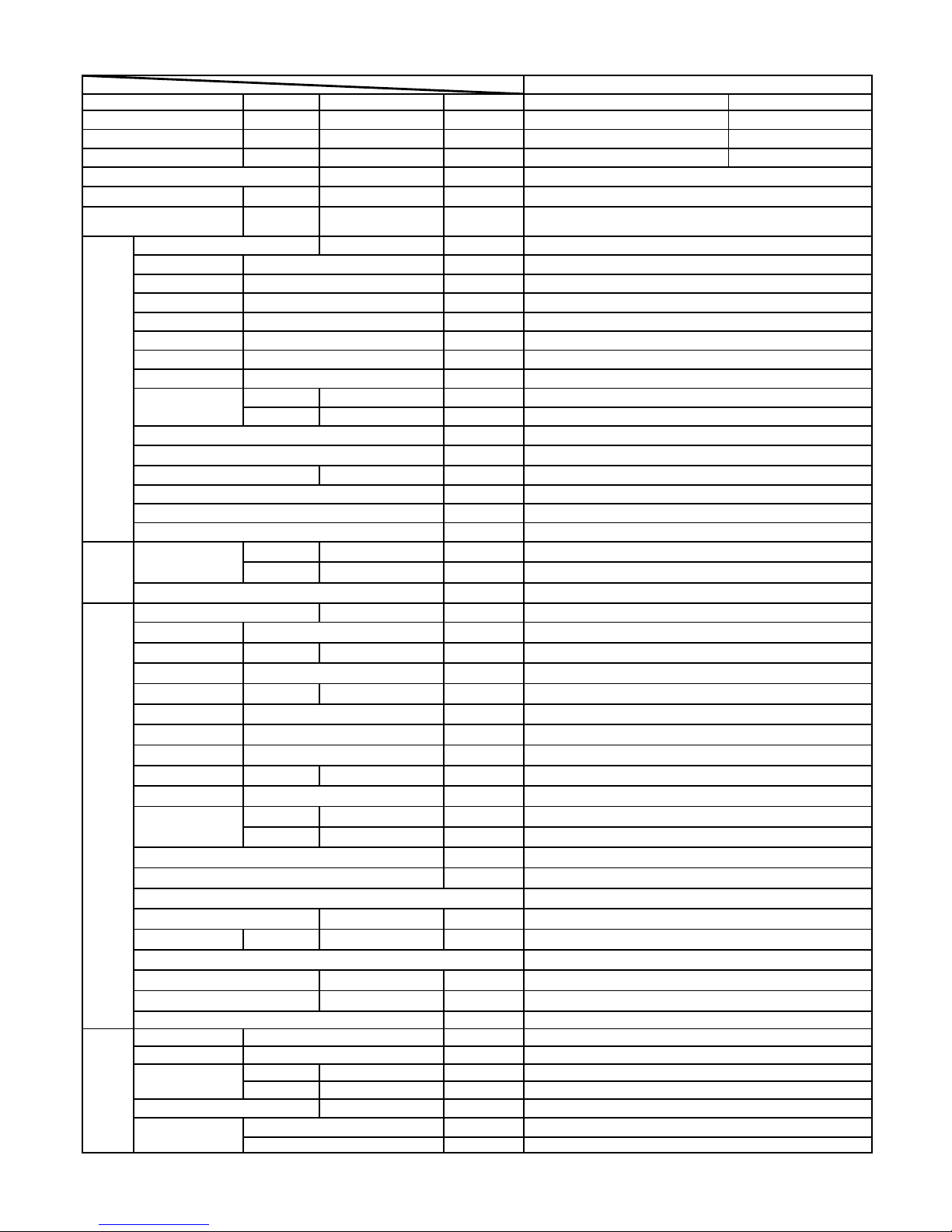
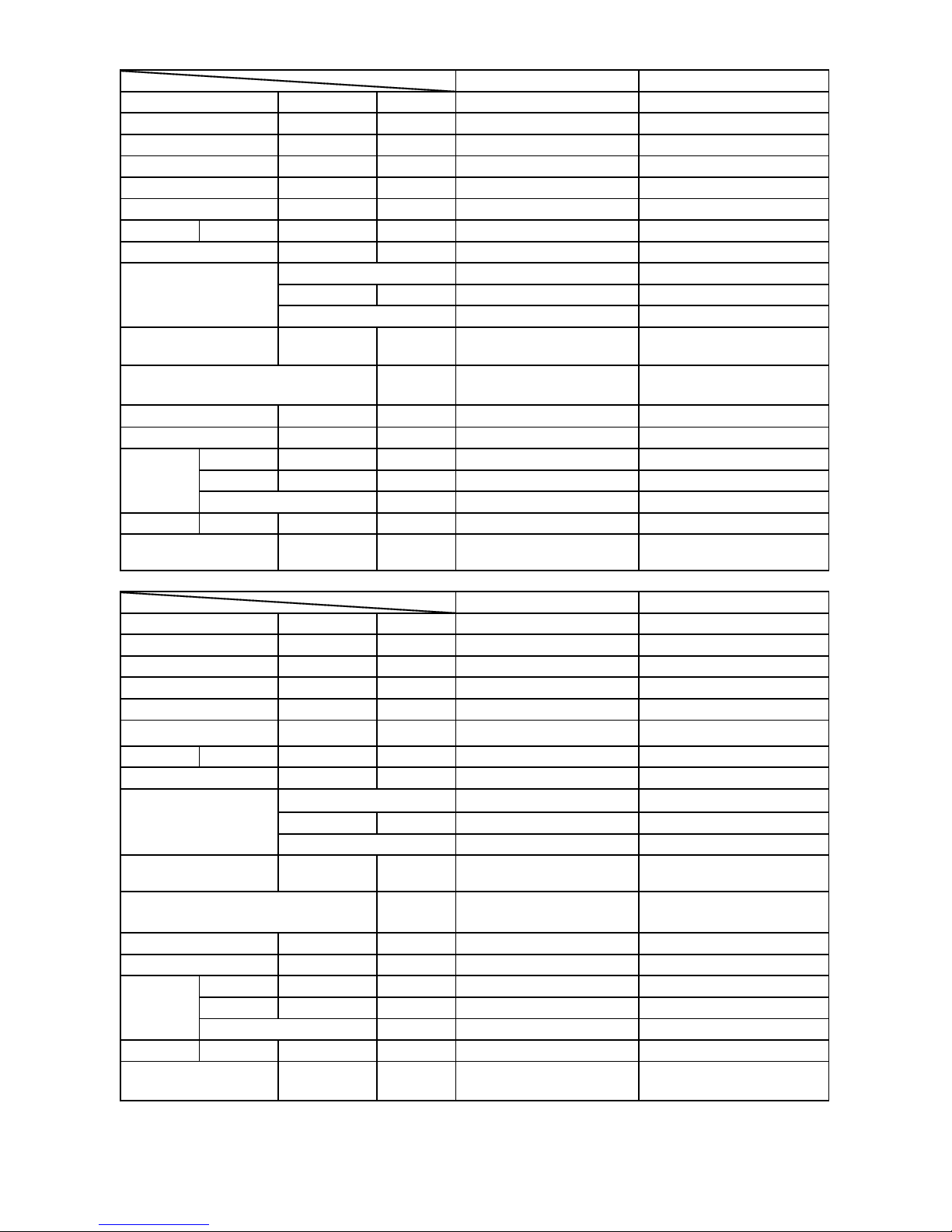
Function Coolin
g
Heatin
g
Capacity BTU/h
48000 56000
W
6000 6000
W
7200W 7000W
Dehumidifying capacity
10‐³×m³/h
Power source
N,V,H
z
A / A
Unit model (color)
Fan Type × Number
Speed(H-M-L) r/min
Fan motor output power kW
Air-flow(H-M-L) m³/h
Heat exchanger Type / Diameter mm
Total Area m²
Temp. scope
℃
External
(L×W×H)
mm×mm×mm
Package
(L×W×H)
mm×mm×mm
Drainage pipe (material , I.D./O.D.) mm
Control type (Remote /wired)
Fresh air hole dimension mm
kW
dB(A)
kg / kg
External
(L×W×H)
mm×mm×mm
Package
(L×W×H)
mm×mm×mm
kg / kg
Unit model (color)
Compressor Model / Manufacture
Type
Fan Type × Number
Speed r/min
Fan motor output power kW
Air-flow(H-M-L) m³/h
Heat exchanger Type / Diameter mm
Total area m²
Temp. scope
℃
External
(L×W×H)
mm×mm×mm
Package
(L×W×H)
mm×mm×mm
Drainage pipe (material , I.D./O.D.) mm
Refrigerant control method mm/mm
Volume of Accumulator L
Noise level dB(A)
material of reduce noise
crankcase heater power W
kg / k
g
Refrigerant Type / Charge
g
Recharge quantit
y
g
/m
Liquid mm
Gas mm
Connecting Method
m
m
PIPING
R22
6500
/
Pipe
9.5
2
1
9.05
flared
Between I.D &O
MAX.Drop 30
Rubber bracke
t
/
Weight (Net / Shipping)
125/14
5
MAX.Piping length
50
/
60/-/-
Type of Four way valve
/
/cap
illary +electrionic expansion valv
e
Defrosting
A
uto
/
Dimension
1250×1035×34
0
1375×1050×44
0
Outdoor unit
WHIT
E
EHV46FAL1/MITSUBISHI
scroll
A
xial-flowX2
840
6500
/
/
Panel
Dimension
/
/
Weight (Net / Shipping)
/
Noise level (H-M-L)
/
Weight (Net / Shipping)
/
/
/
/
Electricity Heater
/
/
/
Dimension /
/
1N 220V 50H
Z
Running current(max. runni
n
current
)
cooling :10/13 heating : 10/12
Indoor unit
/
/
/
/
/
/
Item model
A
U482FIAHA
Total power input
/
Max. power input
Function Coolin
g
Heatin
g
Capacity BTU/h
48000 56000
W
6000 6000
W
7200W 7000W
Dehumidifying capacity
10‐³×m³/h
Power source
N,V,H
z
A / A
Unit model (color)
Fan Type × Number
Speed(H-M-L) r/min
Fan motor output power kW
Air-flow(H-M-L) m³/h
Heat exchanger Type / Diameter mm
Total Area m²
Temp. scope
℃
External
(L×W×H)
mm×mm×mm
Package
(L×W×H)
mm×mm×mm
Drainage pipe (material , I.D./O.D.) mm
Control type (Remote /wired)
Fresh air hole dimension mm
kW
dB(A)
kg / kg
External
(L×W×H)
mm×mm×mm
Package
(L×W×H)
mm×mm×mm
kg / kg
Unit model (color)
Compressor Model / Manufacture
Type
Fan Type × Number
Speed r/min
Fan motor output power kW
Air-flow(H-M-L) m³/h
Heat exchanger Type / Diameter mm
Total area m²
Temp. scope
℃
External
(L×W×H)
mm×mm×mm
Package
(L×W×H)
mm×mm×mm
Drainage pipe (material , I.D./O.D.) mm
Refrigerant control method mm/mm
Volume of Accumulator L
Noise level dB(A)
material of reduce noise
crankcase heater power W
kg / k
g
Refrigerant Type / Charge
g
Recharge quantit
y
g
/m
Liquid mm
Gas mm
Connecting Method
m
mMAX.Piping length
50
PIPING
R22
6500
/
Pipe
9.5
2
1
9.05
flared
Between I.D &O
MAX.Drop 30
Rubber bracket(compressor use
)
/
Weight (Net / Shipping)
125/14
5
/
60/-/-
Type of Four way valve
/
/cap
illary +electrionic expansion valv
e
Defrosting
A
uto
///
Dimension
1250×1035×34
0
1375×1050×44
0
Indoor unit
/
Outdoor unit
WHIT
E
JT100BHVYE/DAIKI
N
scroll
A
xial-flowX2
840
6500
Panel
Dimension
/
/
Weight (Net / Shipping)
/
Noise level (H-M-L)
/
Weight (Net / Shipping)
/
/
/
/
Electricity Heater
/
/
/
/
/
/
/
/
Dimension /
/
/
3N 380V 50H
Z
Running current(max. runni
n
current
)
cooling :10/13 heating : 10/12
Item model
A
U48NFIAHA
Total power input
Max. power input

AB092FCBHA AB142FCBHA
Btu/h 9000 14000
Btu/h 12000 16000
1PH 220-230V 50Hz 1PH 220-230V 50Hz
dB(A) 41/39/35 41/39/35
L/h 1.6 2.1
R407C R407C
External mm 570×570×276 570×570×276
Package mm 715×715×361 715×715×361
Net Kg/Kg 25/4.2 26/4.2
Gross Kg/Kg
27/6.3 28/6.3
Fan Cross flow fan x 1 Cross flow fan x 1
Power output W 15×1 15×1
Relay control Relay control
m3/h 700 700
Liquid mm 6.35 6.35
Gas mm 9.52 12.7
Flared Flared
m
2
13~19 17~27
wireless remote control wireless remote control
AB182FCAHA AB182FCBHA
Btu/h 18000 18000
Btu/h 21000 20000
1PH 220-230V 50Hz 1PH 220-230V 50Hz
dB(A) 43/42/39 41/39/35
L/h 2.1 2.1
R22 R407C
External mm 750×750×320 570×570×276
Package mm 900×900×460 715×715×361
Net Kg/Kg 29/3.5 26/4.2
Gross Kg/Kg
39/5.8 28/6.3
Fan Cross flow fan x 1 Cross flow fan x 1
Power output W 20×1 20×1
Relay control Relay control
m3/h 1000 700
Liquid mm 9.52 9.52
Gas mm 15.88 15.88
Flared Flared
m
2
22~33 25~35
wireless remote control wireless remote control
Suited area
Controller type
Connecting method
Item Model
Suited area
Controller type
Refrigerant control method
Type×Number
Starting method
Air-flow
Heating capacity
Power source
Refrigerant
Heat exchanger
Type×Number
Heat exchanger
Refrigerant control method
Refrigerant
Item Model
Cooling capacity
Heating capacity
Power source
Noise level
H/M/L
Noise level H/M/L
Dehumidifying capacity
Weight
Unit/Panel
Air-flow
Connecting method
Starting method
Combination of wave cranny radiation fin and copper pipe
Fan motor
Capillary + Electronic expansion valve
Dimension
L×W×H
Dehumidifying capacity
Piping
Weight
Unit/Panel
Cooling capacity
Piping
Combination of wave cranny radiation fin and copper pipe
Capillary + Electronic expansion valve
Fan motor
Dimension
L×W×H
4). Cassette type indoor unit
AE072FCAKA AE092FCAKA
Cooling capacity
Btu/h
7000 9000
Heating capacity
Btu/h
9000 11000
Cooling capacity W 1800 2500
Heating capacity W 2400 3000
Dehumidifying capacity
10‐³×m³/h
1.2 1.6
Power source
N,V,Hz
1PH 220V-230V 50HZ 1PH 220V-230V 50HZ
Refrigerant
R22 R22
Noise level(H/M/L) dB(A) 36/-/- 36/-/-
Type × Number
centrifugal fan×2 centrifugal fan×2
Air-flow(H-M-L) m³/h 420 520
starting mothod Relay control Relay control
Heat exchanger
Combination of wave
cranny radiation fin
and copper pipe
Combination of wave
cranny radiation fin
and copper pipe
Refrigerant control method
Capillary + Electronic
expansion valve
Capillary + Electronic
expansion valve
External mm×mm×mm 663×440×225 650×450×225
Net kg / kg 11.6 18
Liquid mm 6.35 6.35
Gas mm 9.52 9.52
Connection method flared flared
Suited area m2 8~16 11~21
Controller type
wired controller or
remote controller
wired controller or
remote controller
AE122FCAKA AE182FCAKA
Cooling capacity
Btu/h
12000 18000
Heating capacity
Btu/h
14000 21000
Cooling capacity W 3200 5000
Heating capacity W 4000 6000
Dehumidifying capacity
10‐³×m³/h
1.8 2.4
Power source
N,V,Hz 1PH 220V-230V 50HZ 1PH 220V-230V 50HZ
Refrigerant
R22 R22
Noise level(H/M/L) dB(A) 38/38/40
40/42/44
Type × Number
centrifugal fan×2 centrifugal fan×2
Air-flow(H-M-L) m³/h 650 1000
starting mothod
Relay control Relay control
Heat exchanger
Combination of wave
cranny radiation fin
and copper pipe
Combination of wave
cranny radiation fin
and copper pipe
Refrigerant control method
Capillary + Electronic
expansion valve
Capillary + Electronic
expansion valve
External mm×mm×mm 804×450×225 1288×225×400
Net kg / kg 20 25
Liquid mm 6.35 9.52
Gas mm 12.7 15.88
Connection method flared flared
Suited area m2 12~23 23~36
Controller type
wired controller or
remote controller
wired controller or
remote controller
Item model
Fan
Dimension (L×W×H)
Weight(unit/panel)
Weight(unit/panel)
Piping
Piping
Item model
Fan
Dimension (L×W×H)
AB092FCAHA AB142FCAHA
Cooling capacity
Btu/h
10000 14000
Heating capacity
Btu/h
12000 17000
Cooling capacity W
3200 4000
Heating capacity W
4000 5000
Dehumidifying capacity
10‐³×m³/h
1.8 1.8
Power source
N,V,Hz
1PH 220V-230V 50HZ 1PH 220V-230V 50HZ
Refrigerant
R22 R22
Noise level(H/M/L) dB(A)
35/39/41 35/39/41
Type × Number
centrifugal fan×1 centrifugal fan×1
Air-flow(H-M-L) m³/h
700 700
starting mothod
Relay control Relay control
Heat exchanger
Combination of wave
cranny radiation fin and
Combination of wave
cranny radiation fin and
Refrigerant control method
Capillary + Electronic
expansion valve
Capillary + Electronic
expansion valve
External
mm×mm×mm
700×570×276 700×570×276
Net kg / kg
26/4.2 26/4.2
Liquid mm
9.52 9.52
Gas mm
15.88 15.88
Connection method
flared flared
Suited area m2
12~23 17~27
Controller type
wired controller or remote
controller
wired controller or remote
controller
AE212FCAKA AE242FCAKA
Cooling capacity
Btu/h
21000 24000
Heating capacity
Btu/h
24000 28000
Cooling capacity W 6000 7100
Heating capacity W 7000 8000
Dehumidifying capacity
10‐³×m³/h
2.4 3
Power source
N,V,Hz
1PH 220V-230V 50HZ 1PH 220V-230V 50HZ
Refrigerant
R22 R22
Noise level(H/M/L) dB(A)
40/42/44
38/42/46
Type × Number
centrifugal fan×2 centrifugal fan×3
Air-flow(H-M-L) m³/h 1000 900~1500
starting mothod
Relay control Relay control
Heat exchanger
Combination of wave
cranny radiation fin and
Combination of wave
cranny radiation fin and
Refrigerant control method
Capillary + Electronic
expansion valve
Capillary + Electronic
expansion valve
External
mm×mm×mm
1024×450×225 1380×450×225
Net kg / kg 25 42
Liquid mm
9.52 9.52
Gas mm
15.88 15.88
Connection method
flared flared
Suited area m2 27~41 32~49
Controller type
wired controller or remote
controller
wired controller or remote
controller
Weight(unit/panel)
Piping
Piping
Item model
Fan
Dimension(L×W×H)
Item model
Fan
Dimension(L×W×H)
Weight(unit/panel)
Btu/h
Btu/h
dB(A)
L/h
External mm
Package mm
Net Kg
Gross Kg
Fan
Power output W
m3/h
Liquid mm
Gas mm
m
2
AC182FCAHA AC182FCBHA
Btu/h 18000 18000
Btu/h 21000 21000
1PH 220-230V 50Hz 1PH 220-230V 50Hz
dB(A) 48/44/38 48/44/38
L/h 2.1 2.1
R22 R407C
External mm 990×655×199 990×655×199
Package mm 1160×760×310 1160×760×310
Net Kg 30 30
Gross Kg
39 39
Fan Centrifugal fan x 1 Centrifugal fan x 1
Power output W 70×1 70×1
Relay control Relay control
m3/h 860 860
Liquid mm 9.52 9.52
Gas mm 15.88 15.88
Flared Flared
m
2
22~33 22~33
wireless remote control wireless remote control
Suited area
Controller type
16~23
wireless remote control
Type×Number
Starting method
Air-flow
Piping
Connecting method
Power source
Refrigerant
Heat exchanger
Refrigerant control method
Controller type
Item Model
Cooling capacity
Heating capacity
Refrigerant
Heat exchanger
Refrigerant control method
Type×Number
Item Model
Cooling capacity
Heating capacity
Power source
30
39
48/44/38
2.1
990×655×199
1160×760×310
AC142FCBHA
14000
16000
1PH 220-230V 50Hz
Fan motor
Centrifugal fan x 1
70×1
Relay control
860
9.52
15.88
Flared
Dehumidifying capacity
Capillary + Electronic expansion valve (PMV)
Capillary + Electronic expansion valve (PMV)
Dimension
L×W×H
Weight
Starting method
Noise level
H/M/L
Fan motor
Air-flow
Piping
Connecting method
Suited area
R407C
Noise level
H/M/L
Dehumidifying capacity
Dimension
L×W×H
Weight
Combination of wave cranny radiation fin and copper pipe
Combination of wave cranny radiation fin and copper pipe
5). Convertible type indoor unit
AD142FCBHA AD182FCBHA
Btu/h 14000 18000
Btu/h 16000 21000
1PH 220-230V 50Hz 1PH 220-230V 50Hz
dB(A) 43/41/38 43/41/38
L/h 1.2 1.2
R407C R407C
External mm 990×650×300 990×650×300
Package mm 1137×800×320 1137×800×320
Net Kg 38 38
Gross Kg 55 55
Fan Centrifugal fan × 2 Centrifugal fan × 2
Power output W 50×2 50×2
Relay control Relay control
m3/h 850 780/710/630
Liquid mm 9.52 9.52
Gas mm 15.88 15.88
Flared Flared
m
2
24~38 24~38
wired remote control wired remote control
AP182FAAHA AP182FABHA
Btu/h 17000 18000
Btu/h 21000 21000
1PH 220-230V 50Hz 1PH 220-230V 50Hz
dB(A) 48/45/39 48/45/39
L/h 2.6 2.6
R22 R407C
External mm 1746×500×250 1746×500×250
Package mm 1862×610×405 1862×610×405
Net Kg 36 36
Gross Kg 49 49
Fan Centrifugal fan × 1 Centrifugal fan × 1
Power output W 70×1 70×1
Relay control Relay control
m3/h 900 800
Liquid mm 9.52 9.52
Gas mm 15.88 15.88
Flared Flared
m
2
23~36 23~36
wireless remote control wireless remote control
Suited area
Controller type
Type×Number
Starting method
Air-flow
Piping
Connecting method
Fan motor
Capillary + Electronic expansion valve
Heat exchanger
Refrigerant control method
Power source
Noise level
H/M/L
Dehumidifying capacity
Refrigerant
Dimension
L×W×H
Heat exchanger
Refrigerant control method
Dimension
L×W×H
Weight
Refrigerant
Capillary + Electronic expansion valve
Fan motor
Dehumidifying capacity
Type×Number
Controller type
Starting method
Item Model
Cooling capacity
Air-flow
Item Model
Cooling capacity
Heating capacity
Noise level
H/M/L
Heating capacity
Power source
Weight
Piping
Connecting method
Suited area
Combination of wave cranny radiation fin and copper pipe
Combination of wave cranny radiation fin and copper pipe
6). Med static pressure duct type indoor unit
7). Cabinet type indoor unit

AE092FCAHA AE092FCBHA
Btu/h 9000 9000
Btu/h 11000 10000
1PH 220-230V 50Hz 1PH 220-230V 50Hz
dB(A) 36/-/- 36/-/-
L/h 1.06 1.06
R22 R407C
External mm 783×225×440 783×225×440
Package mm 924×521×283 924×521×283
Net Kg 14.5 14.5
Gross Kg 17.7 17.7
Fan Centrifugal fan × 2 Centrifugal fan × 2
Power output W / /
Relay control Relay control
m3/h 520 520
Liquid mm 6.35 6.35
Gas mm 9.52 9.52
Flared Flared
m
2
11~21 11~21
wired remote control wired remote control
AE182FCAHA AE182FCBHA
Btu/h 18000 18000
Btu/h 21000 21000
1PH 220-230V 50Hz 1PH 220-230V 50Hz
dB(A) 41/39/36 41/39/36
L/h 2.55 2.55
R22 R407C
External mm 1288×225×400 1288×225×400
Package mm 1390×290×525 1390×290×525
Net Kg 24 24
Gross Kg 27 27
Fan Centrifugal fan × 2 Centrifugal fan × 2
Power output W / /
Relay control Relay control
m3/h 1000 1000
Liquid mm 9.52 9.52
Gas mm 15.88 15.88
Flared Flared
m
2
23~36 23~36
wired remote control wired remote control
Controller type
Refrigerant
Heat exchanger
Refrigerant control method
Type×Number
Suited area
Controller type
Item Model
Cooling capacity
Type×Number
Starting method
Air-flow
Piping
Connecting method
Capillary + Electronic expansion valve
Fan motor
Noise level
H/M/L
Dehumidifying capacity
Heating capacity
Power source
Dimension
L×W×H
Weight
Starting method
Air-flow
Piping
Connecting method
Suited area
Capillary + Electronic expansion valve
Fan motor
Dimension
L×W×H
Weight
Heat exchanger
Refrigerant control method
Noise level
H/M/L
Dehumidifying capacity
Item Model
Cooling capacity
Heating capacity
Power source
Refrigerant
Combination of wave cranny radiation fin and copper pipe
Combination of wave cranny radiation fin and copper pipe
8). Ceiling concealed type indoor unit
AE112FCBIA AE182FCBIA
Btu/h 11000 18000
Btu/h 13600 21000
Btu/h 15400 23000
1PH 220-230V 50Hz 1PH 220-230V 50Hz
Kpa 16 30
L/h 280 660
L 0.63 1.0
W 58 86
dB(A) 42.6/-/- 47.6/-/-
L/h 0.90 1.56
R407C R407C
External mm 863×225×556 1233×225×556
Package mm / /
Weight Net/Gross Kg/Kg 20.8/34.2 27.9/30.9
Fan Centrifugal fan × 2 Centrifugal fan × 2
Power output(W) W / /
Relay control Relay control
m3/h 700 1000
Liquid mm 6.35 9.52
Gas mm 12.7 15.88
Flared Flared
Cooling capacity
Heating capacity
Fan motor
Piping
Noise level
H/M/L
Dehumidifyng capacity
Dimension
L×W×H
Pressure loss of hot water
Item Model
Hot water capacity
Power source
Water-flow
Inner cubage
Air-flow
Connecting method
Motor power
Refrigerant
Type×Number
Starting method
AF092FCBHA AF122FCBHA
Btu/h 9000 12000
Btu/h 11000 13500
1PH 220-230V 50Hz 1PH 220-230V 50Hz
dB(A) 37/34/30 37/34/30
L/h 1.6 1.6
R407C R407C
External mm 783×225×440 783×225×440
Package mm 936×298×533 936×298×533
Net Kg 17 17
Gross Kg 17.7 17.7
Fan Cross flow fan Cross flow fan
Power output W upper:20W, nether:11W upper:20W, nether:11W
Relay control Relay control
m3/h 600 600
Liquid mm 6.35 6.35
Gas mm 12.7 12.7
Flared Flared
m
2
10~20 16~26
wireless remote control wireless remote control
Noise level
H/M/L
Dehumidifying capacity
Weight
Piping
Fan motor
Type×Number
Starting method
Air-flow
Item Model
Cooling capacity
Heating capacity
Power source
Combination of wave cranny radiation fin and copper pipe
Refrigerant control method Capillary + Electronic expansion valve
Dimension
L×W×H
Connecting method
Suited area
Controller type
Refrigerant
Heat exchanger
9). Ceiling concealed type TES indoor unit
10). Console type indoor unit
AS092FMAHA AS092FMBHA
Btu/h 11000 9000
Btu/h 14000 10000
1PH 220-230V 50Hz 1PH 220-230V 50Hz
dB(A) 39/37/30 39/37/30
L/h 1.6 1.6
R22 R407C
External mm 795×182×265 795×182×265
Package mm 860×335×270 860×335×270
Net Kg 7.6 7.6
Gross Kg 10.6 10.6
Fan Cross flow fan x 1 Cross flow fan x 1
Power output W 20×1 20×1
Controllable silicon control Controllable silicon control
m3/h 500 500
Liquid mm 6.35 6.35
Gas mm 12.7 12.7
Flared Flared
m
2
11~21 11~21
wireless remote control wireless remote control
AS182FTAHA AS182FTBHA
Btu/h 18000 18000
Btu/h 21000 21000
1PH 220-230V 50Hz 1PH 220-230V 50Hz
dB(A) 47/45/42 47/45/42
L/h 2.1 2.1
R22 R407C
External mm 1100×330×205 1100×330×205
Package mm 1177×412×291 1177×412×291
Net Kg 14 14
Gross Kg 17 17
Fan Screw fan x 2 Screw fan x 2
Power output W 60×2 60×2
Controllable silicon control Controllable silicon control
m3/h 800 800
Liquid mm 9.52 9.52
Gas mm 15.88 15.88
Flared Flared
m
2
24~38 24~38
wireless remote control wireless remote control
Controller type
Air-flow
Piping
Connecting method
Suited area
Air-flow
Connecting method
Suited area
Controller type
Noise level
H/M/L
Dehumidifying capacity
Item Model
Cooling capacity
Heating capacity
Power source
Dimension
L×W×H
Weight
Refrigerant
Heat exchanger
Capillary + Electronic expansion valve
Fan motor
Refrigerant control method
Type×Number
Starting method
Piping
Noise level
H/M/L
Item Model
Cooling capacity
Heating capacity
Power source
Dehumidifying capacity
Dimension
L×W×H
Weight
Refrigerant
Fan motor
Capillary + Electronic expansion valve
Heat exchanger
Refrigerant control method
Type×Number
Starting method
Combination of wave cranny radiation fin and copper pipe
Combination of wave cranny radiation fin and copper pipe
11). Wall-mounted type indoor unit
AS072FMAHA
AS122FMAHA
Cooling capacity
Btu/h
7000
12000
Heating capacity
Btu/h
9000
14000
Cooling capacity W
2500
4000
Heating capacity W
3000
5000
Dehumidifying capacity
10‐³×m³/h
1.19
2.1
Power source
N,V,Hz
1PH 220V-230V 50HZ 1PH 220V-230V 50HZ
Refrigerant
R22 R22
Noise level(H/M/L) dB(A)
30/37/39
33/38/41
Type × Number
cross fan×1
A
ir-flow(H-M-L m³/h
420
600
starting mothod
Relay control Relay control
Heat exchanger
Combination of wave
cranny radiation fin and
Combination of wave cranny
radiation fin and copper pipe
Refrigerant control method
Capillary + Electronic
expansion valve
Capillary + Electronic
expansion valve
External
mm×mm×mm
795×265×182
938×265×182
Net kg / kg
7.2
11
Liquid mm
6.35 6.35
Gas mm
9.52 12.7
Connection method
flared flared
Suited area m2
11~21
17~27
Controller type
wired controller or remote
controller
wired controller or remote
controller
AE142FCAKA AS122FBBHA
Cooling capacity
Btu/h
14000 12000
Heating capacity
Btu/h
16000 17000
Cooling capacity W
4000 4000
Heating capacity W
5000 5000
Dehumidifying capacity
10‐³×m³/h
2 2.1
Power source
N,V,Hz
1PH 220V-230V 50HZ 1PH 220V-230V 50HZ
Refrigerant
R22 R407C
Noise level(H/M/L) dB(A) 38/41/42 41/38/33
Type × Number
centrifugal fan×2 cross-flow fan×2
A
ir-flow(H-M-L m³/h 700 600
starting mothod
Relay control Relay control
Heat exchanger
Combination of wave
crann
y
radiation fin and
Combination of wave cranny
radiation fin and copper pipe
Refrigerant control method
Capillary + Electronic
expansion valve
Capillary + Electronic
expansion valve
External
mm×mm×mm
804×450×225 938*265*182
Net kg / kg 20 11
Liquid mm 6.35 6.35
Gas mm 12.7 12.7
Connection method
flared flared
Suited area m2 17~27 17~27
Controller type
wired controller or remote
controller
wired controller or remote
controller
Weight(unit/panel)
Piping
Piping
Item model
Fan
Dimension(L×W×H)
Item model
Fan
Dimension(L×W×H)
Weight(unit/panel)

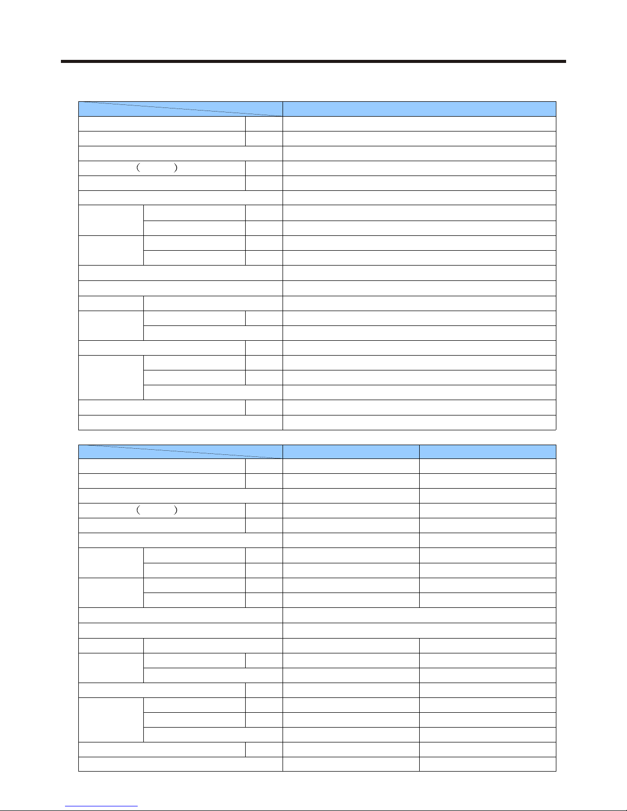
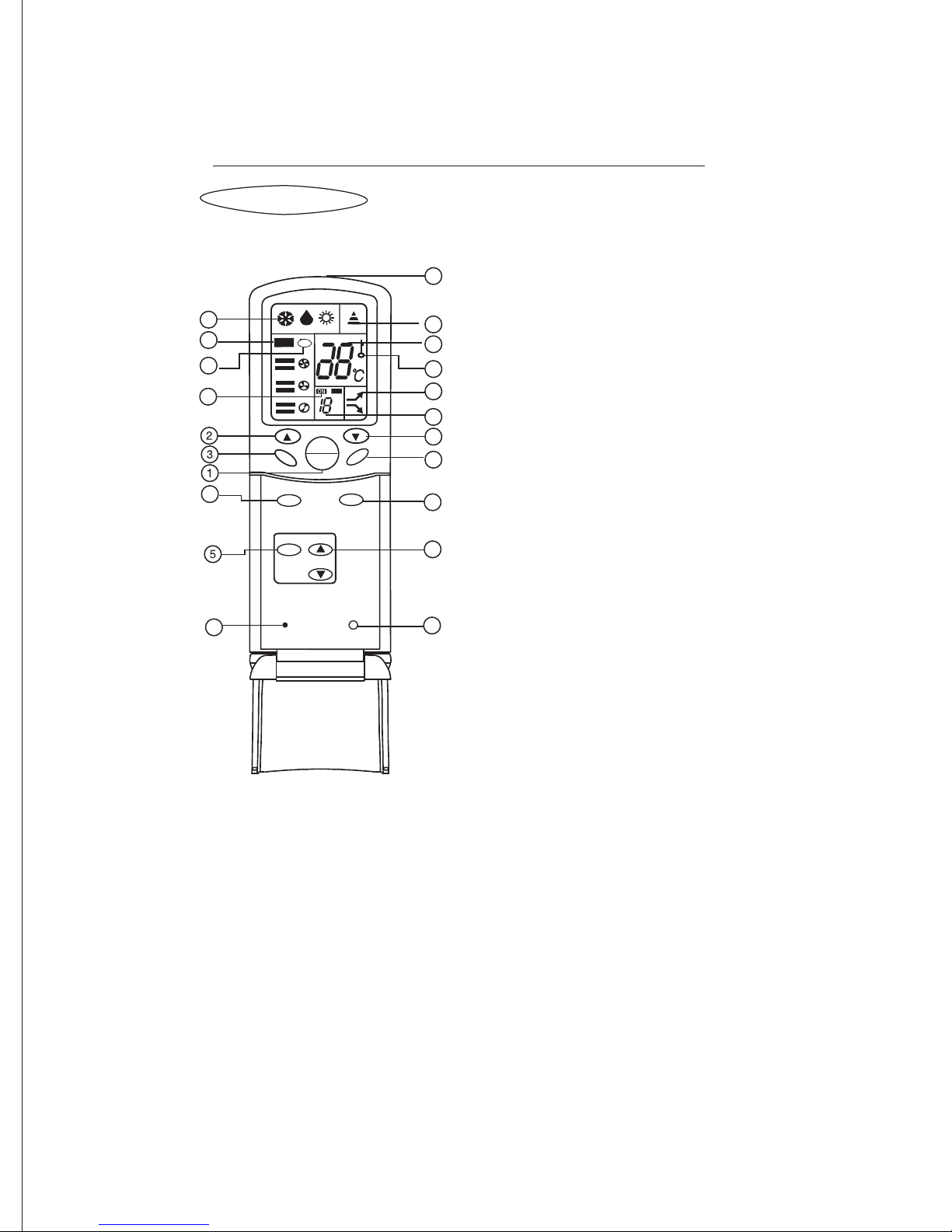
3.1 Controllers
3.1.1 Wireless remote controller
3 MECHANICAL DATA
1.Default mode of the air conditioner will resume if the battery in the remote controller is replaced:
Mode: Cooling; Temperature: 26°C;
Timing: Normal; Airflow speed: Auto
Mode
Timing mode
Ion emission
Sending signals to the indoor
unit receiver
Operation option display
Display of set temperature
value
Flashing while the signal is
sent
Display of the time set
for timer on or off.
Ion performance display
Airflow volume display
Speed is automatically adjusted by the
air conditioner according to room
and set temperatures.
For desired room
temperature
For timing mode option
Increase and decrease
For desired airflow speed
For cooling, dehumidifying or heating
For airflow direction
adjustment
For ion emission
setting
Airflow volume
Signal Transmitter
Temperature
Signal icon
Temperature setting
Time setting
Airflow volume
Turning the appliance on or
off
On/Off
Airflow direction
Ion emission
Timing period
Mode option
Timer
AUTO
C
ON OFF
H
ion
Reset
Press with a pointed article
to reset value if abnormal
operation occurs.
Timing mode display
Normal
Timer Off
Timer On
RESET
TEMER
MODE
SWING
HEALTH
FAN SPEED
ON/OFF
TEMP
Cautions:
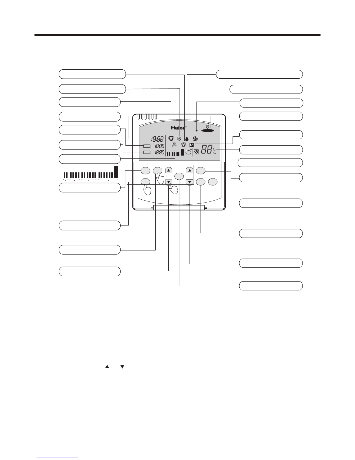
Buttons and display of the remote controller
After replacing the batteries,press the "ON/OFF",remote controller will
display as follows:
MODE:cooling, TEMP.:26
TIMER:normal,FAN:auto
11.DISPLAY MODE
14.TIMER DISPLAY
13.HEALTH DISPLAY
used to emit the sign to indoor
receiver
display the selected mode
display the temp. enacted.
it flashes when you emit
sign to indoor unit
used to show health state
used to select your
desired temp.
used to select:TIMER
ON,TIMER OFF
used to select cooling
d
ehumidity heating
7.FAN
20.EMITTING PART
15.SIGNAL
2.TEMPERATURE
9.SET TIMER
12.DISPLAY FAN SPEED
used for unit start and stop
1.POWER ON/OFF
3.HEALTH
4.MODE
5.TIMER
used to select your desired
fan speed
press it with a needle
to normal condition
6.RESET
8.SWING
used to set fan direction
press it to lock buttons and
press again to cancel lock
10.LOCK
used to display difference
between indoor temp,and
enacted temp.
display the timer state:
"normal":no timer
"off":set time to shut off
"on":set time to start
show that buttons have
been locked
16.TEMP. DISPLAY
17.LOCK DISPLAY
18.MIGHT/QUIET DISPLAY
19.TIME DISPLAY
display the time of "TIMER
ON" and "TIMER OFF"
used to control the
function of oxygenmaking and ion-adding
(when oxygen device and
ion-generator are both
acquirable*health
button can control them,
whether oxygen device is
acquirable lies on the
function of its outdoor.)
RESET
LOCK
OFF
H
AUTO
ion
WING
6
4
2
7
8
9
10
12
13
14
15
16
17
18
19
11
20
***
Remote controller
TEMP
HEALTH
FAN
ON
OFF
MODE
TIMER
NOTE:
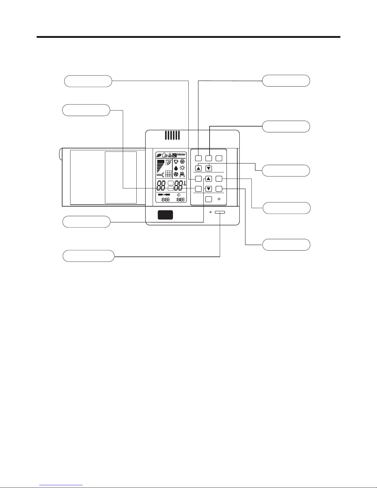
3.1.2 Wired remote controller (old type)
Heating operation indication
For adjusting the clock and
time for timer operation.
Note: This model of air conditioner doesnt provide the air sending direction adjustment function and thus
the "LOU" key is disengaged while the automatic air direction indication may be displayed.
This remote controller hasn't electric-aided heating indication as well as anion generation function
and indication.
AM
PM
ion
R
Cooling operation indication
Dehumidifying operation indication
Fan only operation indication
Operation indicator
Sleep status indication
Temperature display
Automatic louver indication
1
2
LOU key
FAN SPEED key
TEMP step key
Used to select fan speed:
LOW, MID, HI, AUTO.
Used to turn on /off the machine.
Used to select operation mode:
AUTO, COOL, DRY, HEAT, FAN.
For setting a desired temperature value.
Power ON/OFF key
CLOCK key
TIMER key
SET key
HOUR step key
SLEEP key
For checking the clock time.
For selecting timer mode:
TIMER ON
TIMER OFF
TIMER ON/OFF
For setting the clock and time
for timer operation.
For setting the sleep status.
3
Automatic operation
Clock display
TIMER ON display
TIMER OFF display
Fan speed display
MODE key
Used to select an automatic
or fixed air supplying direction.
When unit is started for the first time, clock should be adjusted as follows:
1. Press "CLOCK" key, "AM" or "PM" flashes at the clock display area.
2. Press the HOUR " "or " " key to set correct time. Each press will increase or decrease the time by 1 min.
If the key is kept depressed, time will change quickly.
3. After time setting is confirmed, press "SET" key, "AM" or "PM" stop flashing, while clock starts working.
Clock Set
L L M L M H L M H
AUTO
AM
PM
AM
PM
TIMER ON
TIMER OFF
LOW MIN HIGH
AUTO
ROOM TEMP
SET TEMP
TIMER
SET
CLOCK
TIME
SLEEP
TEMP
SWING
FAN
SPEED
MODE
CLOCK
Used to set correct time.
TIMER
Used to select
TIMER ON,
TIMER OFF,
TIMER ON/OFF.
TIME
Used to set clock and
timer setting.
Used for unit start and
stop.
Power ON/OFF
MODE
Used to select AUTO
RUN, COOL, DRY,
HEAT and FAN
operation.
FAN SPEED
Used to select fan
speed: LO, MED, HI,
AUTO
TEMP
Used to select your
desired temp.
SET
Used to confirm Timer
and Clock settings.
SLEEP
Used to select sleep
mode.
AMPMAM
PM
*
AUTO
%
SET
ROOM
ON OFF
MODE
FAN SWING
TEMP
CLOCK SET
TIMER SLEEP
RESET
FILTER RESET
ON/OFF
3.1.3 Wired remote controller (new type)
The above information is the explanation of the displayed information therefore varies with those displayed
in actual operation.
Note:
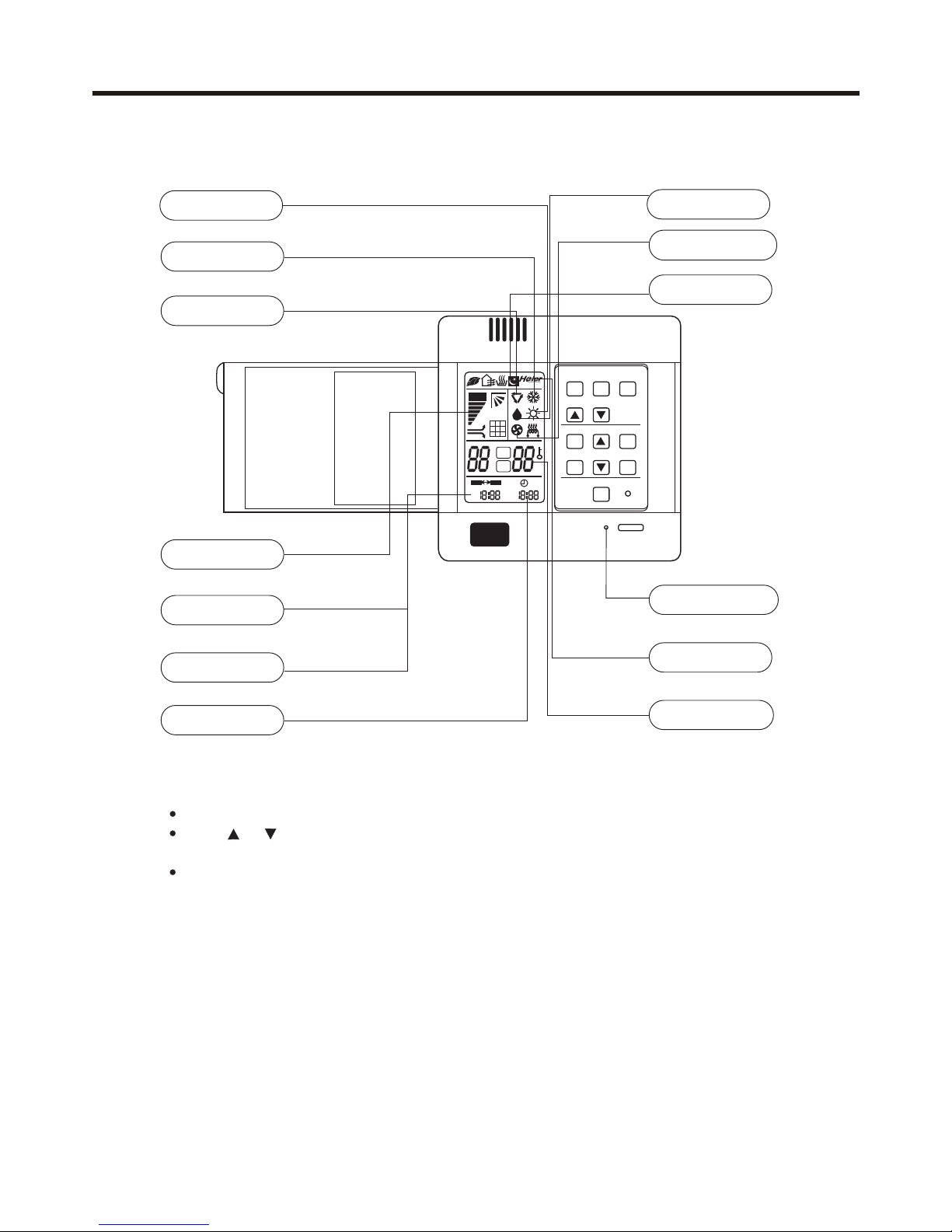
OPERATING LAMP
DRY
COOL
AUTO
F AN SPEED
SLEEP
TIMER ON
TIMER OFF
CLOCK
TEMP.
F AN OPERATION
HEAT
Clock set
When unit is started for the first time, clock should be adjusted as follows:
Press CLOCK button, "AM"or "PM" flashes.
Press or to set correct time. Each press will increase or decrease 1min. If the
button is kept depressed, time will change quickly.
After time setting is confirmed, press SET , "AM "and "PM" stop flashing, while clock
starts working.
Remote control
AM
PM
AM
PM
•
AUTO
%
SET
ROOM
ON OFF
MODE
FAN SWING
TEMP
CLOCK SET
TIMER SLEEP
RESET
FILTER RESET
ON/OFF
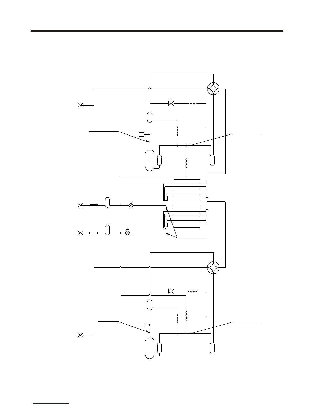
3.2.1 Model AU422FIAHA / AU422FIAIA / AU422FIBIA
Electromagnetic
valve
Capillary
Compressor
Oil separator
Pressure switch
Gas & liquid
separator
Suction air
temperature sensor
4-way valve
Capillary
Capillary
Oil separator
Electromagnetic
valve
Discharging air
temperature
sensor
Refrigerant
storage device
Refrigerant
storage device
2-way stop
valve
2-way stop
valve
Filter
Electronic
expansion valve
Electronic
expansion valve
Filter
Compressor
Pressure switch
3-way stop
valve
Outdoor heat
exchanger
Defrosting &
evaporating sensor
Gas & liquid
separator
Capillary
Capillary
Suction air
temperature sensor
4-way valve
Capillary
3.2 Refrigerant Diagram
 Loading...