

Haier 3U55S2SR2FA, AB35S2SC1FA, AB25S2SC1FA, 5U105S2SS2FA, AB50S2SC1FA Service Manual
...
SYJS-07-2018 REV.A Edition: 2018-07
R32 Super Match
II
Multi Split

CONTENTS
Part 1 General Information .......................................................................................................................................1
1. Lineup ......................................................................................................................................................................1
2. Feature ....................................................................................................................................................................3
Part 2 Indoor Units-4-Way Cassette Type................................................................................................................5
1. Feature ....................................................................................................................................................................6
2. Specication ............................................................................................................................................................8
3. Dimension..............................................................................................................................................................12
4. Wiring Diagram ......................................................................................................................................................14
5. Air Velocity and Temperature Distribution ..............................................................................................................17
6. Sound Pressure level ............................................................................................................................................19
7. Installation .............................................................................................................................................................21
Part 3 Indoor Units -Low Pressure Slim Duct Type ..............................................................................................33
1. Feature ..................................................................................................................................................................34
2. Specication ..........................................................................................................................................................36
3. Dimension..............................................................................................................................................................44
4. Wiring Diagram ......................................................................................................................................................45
5. Airow and Static Pressure Chart ..........................................................................................................................46
6. Installation .............................................................................................................................................................48
Part 4 Indoor Units -Medium Pressure Slim Duct Type .......................................................................................59
1. Specication ..........................................................................................................................................................60
2. Dimension..............................................................................................................................................................71
3. Wiring Diagram ......................................................................................................................................................76
4. Airow and Static Pressure Chart ..........................................................................................................................80
5. Instalaltion .............................................................................................................................................................85
Part 5 Outdoor Units .............................................................................................................................................105
1. Feature ................................................................................................................................................................106
2. Dimension............................................................................................................................................................117
3. Wiring Diagram ....................................................................................................................................................121
4. Wiring Connection ...............................................................................................................................................124
5. Piping Diagram ....................................................................................................................................................127
6. Limitation Values on Pipe lnstallation ..................................................................................................................131
7. Combination and the Data ...................................................................................................................................134
8. Performance Curve .............................................................................................................................................160
9. Sound Pressure level ..........................................................................................................................................163
10. Installation Instructions ......................................................................................................................................167
Part 6 Electric Control and Troubleshooting ......................................................................................................195
1. Indoor PCB Photo................................................................................................................................................196
2. Outdoor unit PCB Photo, Dip Switch Setting and Function .................................................................................206
3. Diagnostic Code ..................................................................................................................................................223
4. Trouble Shooting .................................................................................................................................................233

1
Part 1 General Information
1. Lineup ......................................................................................................................................................................1
2. Feature ....................................................................................................................................................................2
1
Model Apperance
Indoor Unit
4-Way Cassette
AB25S2SC1FA
AB35S2SC1FA
AB50S2SC1FA
AB71S2SG1FA
Low ESP Duct
AD25S2SS1FA
AD35S2SS1FA
AD25S2SS2FA
AD35S2SS2FA
AD50S1SS2FA
AD50S2SS2FA
AD71S2SS1FA
AD71S2SS2FA
Model Apperance
Outdoor Unit
1U71S2SG1FA
3U55S2SR2FA
3U70S2SR2FA
4U75S2SR2FA
4U85S2SR2FA
5U105S2SS2FA
1. Lineup
2
Model Apperance
Indoor Unit Medium Pressure Duct
AD35S2SM3FA
AD50S2SM1FA
AD71S2SM1FA
AD71S2SM3FA
AD90S2SM3FA
AD105S2SM3FA
AD125S2SM3FA
AD140S2SM3FA
3
2. Feature
Clean Design
High Comfort
High Efciency
The outdoor unit takes no screw clean design in the top cover, this design makes people comfort when they are
watching the outdoor unit;
New outdoor unit and indoor unit design to get a ultra high SEER/SCOP A+++/A++ which is reaching the world
class energy efciency (3U55)
The new outdoor unit takes 550mm diameter large fan design, multi split II outdoor unit can provide same air ow
but with lower fan rotation speed, then the sound level reduce 3-4 dB(A) comapred with rst generation multi split
outdoor unit;
550mm
4
Installation Friendly
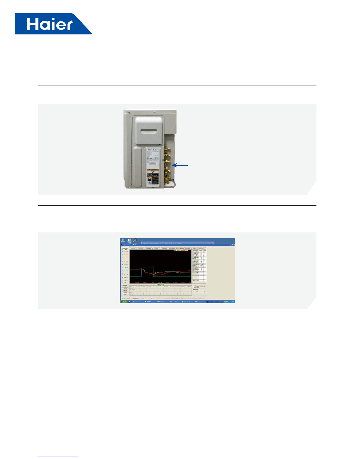
External General Stop Valve
Easy Start Up & Maintenance
The outdoor unit takes external general stop valve in all outdoor unit design, installer can vaccum/charge just one
time with no extra dismantlement, save lots of time;
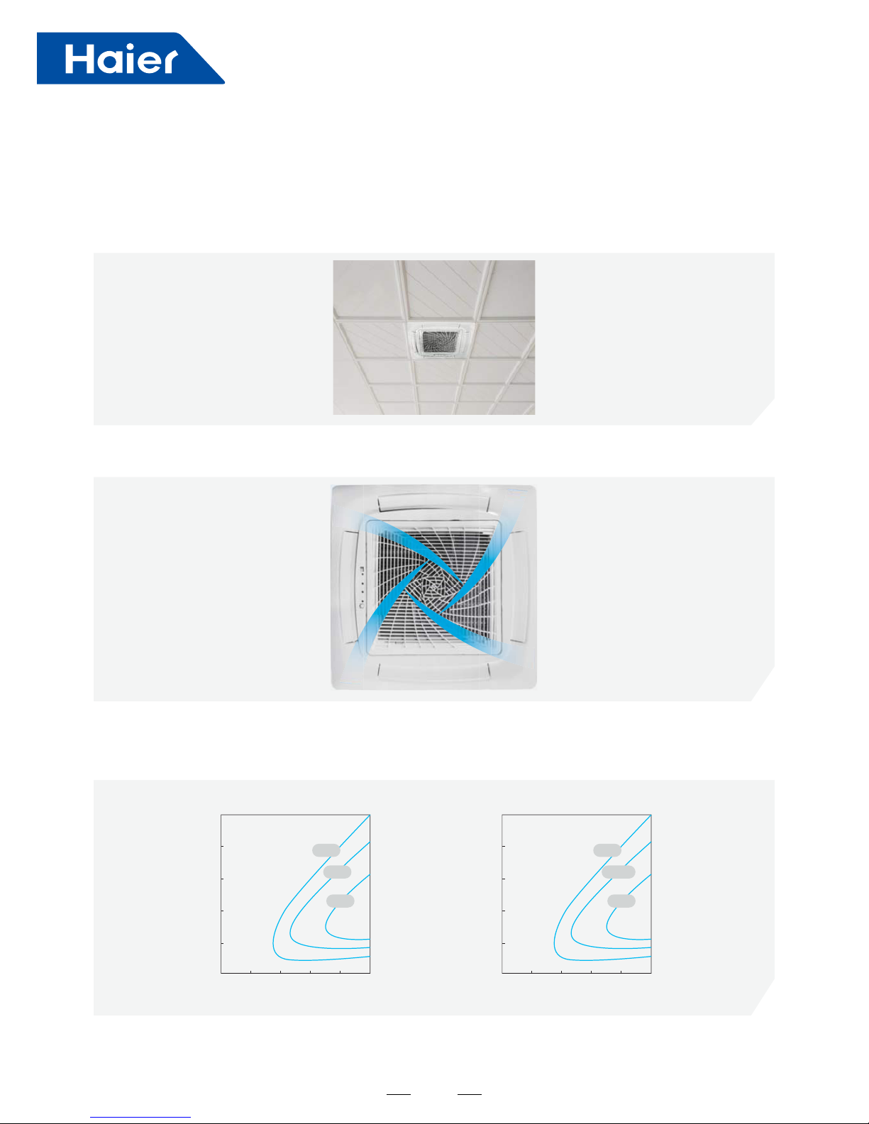
In start up & maintenance, PC monitor can connect with outdoor unit by TD-02, read all indoor unit & outdoor
unit running parameter, also with the function to show parameter & curve.
When malfunction happens, show failure code.
General
stop valve

5
Part 2 Indoor Units-4-Way Cassette Type
1. Feature ....................................................................................................................................................................6
2. Specication ............................................................................................................................................................8
3. Dimension..............................................................................................................................................................12
4. Wiring Diagram ......................................................................................................................................................14
5. Air Velocity and Temperature Distribution ..............................................................................................................17
6. Sound Pressure level ............................................................................................................................................19
7. Installation .............................................................................................................................................................21
6
1. Feature
Appearance
Energy Efciency
DC Fan Motor
"Spiral" panel
The new 620mm*620mm panel is very t for thestandard decoration panel, won't cover otherthings like light, looks
more beautiful;
Compared to conventional AC fan motor, DC fan motor is more efciency.
AC Motor Effciency DC Motor Effciency
“Spiral” concept, “Haier” image;
The new 620mm*620mm panel
20
0
2004 00 6008 00 1000
40
60
80
100
45%
35%
25%
20
0
2004 00 6008 00 1000
40
60
80
100
90%
87.5%
85%
Torque(kgfcm)
Rev(r/min) Rev(r/min)
Torque(kgfcm)
7
Four aps can be controlled individually, airow can be controlled according to end user needs. Increase comfort;
Individual Flap Control
Comfort
Installation Friendly
Easy Access Electrical Box Design
The electrical box is located in the unit, you can just make maintenance by openning the panel .
Horizontal
Adjustable
Downward
corner installation solution
Fixed
8
2. Specication
Item Model AB25S2SC1FA
Function —— Cooling Heating
Capacity W 2600 3200
Sensible heat ratio W 0.71 /
Dehumidifying capacity 10-³xm³/h 1.0
Indoor unit
Power supply 1PH, 220-240V~, 50/60Hz
Fan
Type × Number —— Centrifugal*1
Speed(H-M-L) r/min 690/620/560/500
Fan motor output/input power W 10/15
Air-ows (H-M-L) m³/h 620/520/450/350
Heat exchanger
Type / Diameter mm Inner grooved pipe/φ7.0
Row —— 1
Total area m² 0.272
Temp.scope °C 2.0-7.0
Dimension
(LxWxH)
External mmxmmxmm 570*570*260
Package mmxmmxmm 718*680*380
Drainage pipe (Material,I.D/O.D) mm PVC 26/32
Control type(Remote/Wired) Remote YR-HBS01(O) or Wired YR-E17(O)
Fresh air hole dimension mm 95
Electricity Heater kW None
Noise level
(H-M-L)
Sound power level dB(A) 52
Sound pressure level dB(A) 36/33/30/27
Weight(Net/Shipping) kg/kg 17/20
Panel
Panel model(Color) PB-700IB(White)
Dimension
External(L*W*H) mmxmmxmm 700*700*60
Package(L*W*H) mmxmmxmm 740*750*115
Weight(Net/Shipping) kg/kg 2.8/4.8
Piping
Refrigerant Type R32
Pipe
Liquid mm Φ6.35(1/4)
Gas mm Φ9.52(3/8)
Connecting method Flared
Norminal condition: indoor temperature (cooling): 27°CDB/19°CWB, indoor temperature (heating): 20°CDB
Outdoor temperature(cooling): 35°CDB/24°CWB, outdoor temperature(heating): 7°CDB/6°CWB
The noise level will be measured in the third octave band limited values, using a Real Time Analyser calibrated sound
intensity meter.
9
Item Model AB35S2SC1FA
Function —— Cooling Heating
Capacity W 3500 4000
Sensible heat ratio W 0.71 /
Dehumidifying capacity 10-³xm³/h 1.5
Indoor unit
Power supply 1PH, 220-240V~, 50/60Hz
Fan
Type × Number —— Centrifugal*1
Speed(H-M-L) r/min 690/620/560/500
Fan motor output/input power W 10/15
Air-ows (H-M-L) m³/h 620/520/450/350
Heat exchanger
Type / Diameter mm Inner grooved pipe/φ7.0
Row —— 2
Total area m² 0.544
Temp.scope °C 2.0-7.0
Dimension
(LxWxH)
External mmxmmxmm 570*570*260
Package mmxmmxmm 718*680*380
Drainage pipe (Material,I.D/O.D) mm PVC 26/32
Control type(Remote/Wired) Remote YR-HBS01(O) or Wired YR-E17(O)
Fresh air hole dimension mm 95
Electricity Heater kW None
Noise level
(H-M-L)
Sound power level dB(A) 52
Sound pressure level dB(A) 36/33/30/27
Weight(Net/Shipping) kg/kg 18.5/22
Panel
Panel model(Color) PB-700IB(White)
Dimension
External(L*W*H) mmxmmxmm 700*700*60
Package(L*W*H) mmxmmxmm 740*750*115
Weight(Net/Shipping) kg/kg 2.8/4.8
Piping
Refrigerant Type R32
Pipe
Liquid mm Φ6.35(1/4)
Gas mm Φ9.52(3/8)
Connecting method Flared
Norminal condition: indoor temperature (cooling): 27°CDB/19°CWB, indoor temperature (heating): 20°CDB
Outdoor temperature(cooling): 35°CDB/24°CWB, outdoor temperature(heating): 7°CDB/6°CWB
The noise level will be measured in the third octave band limited values, using a Real Time Analyser calibrated sound
intensity meter.
10
Item Model AB50S2SC1FA
Function —— Cooling Heating
Capacity W 5000 5500
Sensible Heat Ratio W 0.71 /
Dehumidifying Capacity 10-³xm³/h 2.2
Indoor Unit
Power Supply 1PH, 220-240V~, 50/60Hz
Fan
Type × Number —— Axial Fiow*1
Speed (H-M-L) r/min 800/700/600
Fan Motor Output/Input
Power
W 33/50
Air-Flows (H-M-L) m³/h 700/620/500
External Static Pressure pa 0
Heat Exchanger
Type / Diameter mm Inner Grooved Pipe/¢7.0
Row —— 2
Total Area m² 1.25
Dimension
(LxWxH)
External mmxmmxmm 570x570x260
Package mmxmmxmm 718x680x380
Drainage Pipe (Material, I.D/O.D) mm PVC 27/31
Control Type (Remote/Wired) Remote YR-HBS01
Fresh Air Hole Dimension mm None
Electricity Heater kW None
Noise Level
(H-M-L)
Sound Power Level dB (A) 55
Sound Pressure Level dB (A) 42/37/35
Weight (Net/Shipping) kg/kg 18.5/22
Panel
(Optional)
Panel Model (Color) PB-700KB
Dimension
External (L*W*H) mmxmmxmm 700/700/60
Package (L*W*H) mmxmmxmm 740/750/115
Weight (Net/Shipping) kg/kg 2.8/4.8
Piping
Refrigerant Type R32
Pipe
Liquid mm Φ6.35 (1/4)
Gas mm Φ12.7 (1/2)
Connecting Method Flared
Norminal condition: indoor temperature (Cooling): 27℃DB/19℃WB, indoor temperature (Heating): 20℃DB
Outdoor temperature (Cooling): 35℃DB/24℃WB, outdoor temperature (Heating): 7℃DB/6℃WB
The noise level will be measured in the third octave band limited values, using a Real Time Analyser calibrated
sound intensity meter.
11
Item Model AB71S2SG1FA
Function —— Cooling Heating
Capacity W 7100 8000
Sensible Heat Ratio W 0.71 /
Dehumidifying Capacity 10-³xm³/h 1.0
Indoor Unit
Power Supply 1PH, 220-240V~, 50/60Hz
Fan
Type × Number —— Centrifugal*2
Speed (H-M-L) r/min 650/600/550/500
Fan Motor Output/Input
Power
W 45/50
Air-Flows (H-M-L) m³/h 1260/1070/820/680
External Static Pressure pa 0
Heat Exchanger
Type / Diameter mm Inner Grooved Pipe/¢7.0
Row —— 2
Total Area m² /
Temp.Scope °C 2.0-7.0
Dimension
(LxWxH)
External mmxmmxmm 840*840*204
Package mmxmmxmm 990*990*310
Drainage Pipe (Material, I.D/O.D) mm PVC 26/32
Control Type (Remote/Wired) Remote YR-HBS01(O)
Fresh Air Hole Dimension mm None
Electricity Heater kW None
Noise Level
(H-M-L)
Sound Power Level dB (A) 55
Sound Pressure Level dB (A) 36/33/29/26
Weight (Net/Shipping) kg/kg 27/32
Panel
(Optional)
Panel Model (Color) PB-950KB
Dimension
External (L*W*H) mmxmmxmm 950/950/50
Package (L*W*H) mmxmmxmm 1000/1000/110
Weight (Net/Shipping) kg/kg 6.5/9
Piping
Refrigerant Type R32
Pipe
Liquid mm Φ9.52 (3/8)
Gas mm Φ15.88 (5/8)
Connecting Method Flared
Norminal condition: indoor temperature (Cooling): 27℃DB/19℃WB, indoor temperature (Heating): 20℃DB
Outdoor temperature (Cooling): 35℃DB/24℃WB, outdoor temperature (Heating): 7℃DB/6℃WB
The noise level will be measured in the third octave band limited values, using a Real Time Analyser calibrated
sound intensity meter.
12
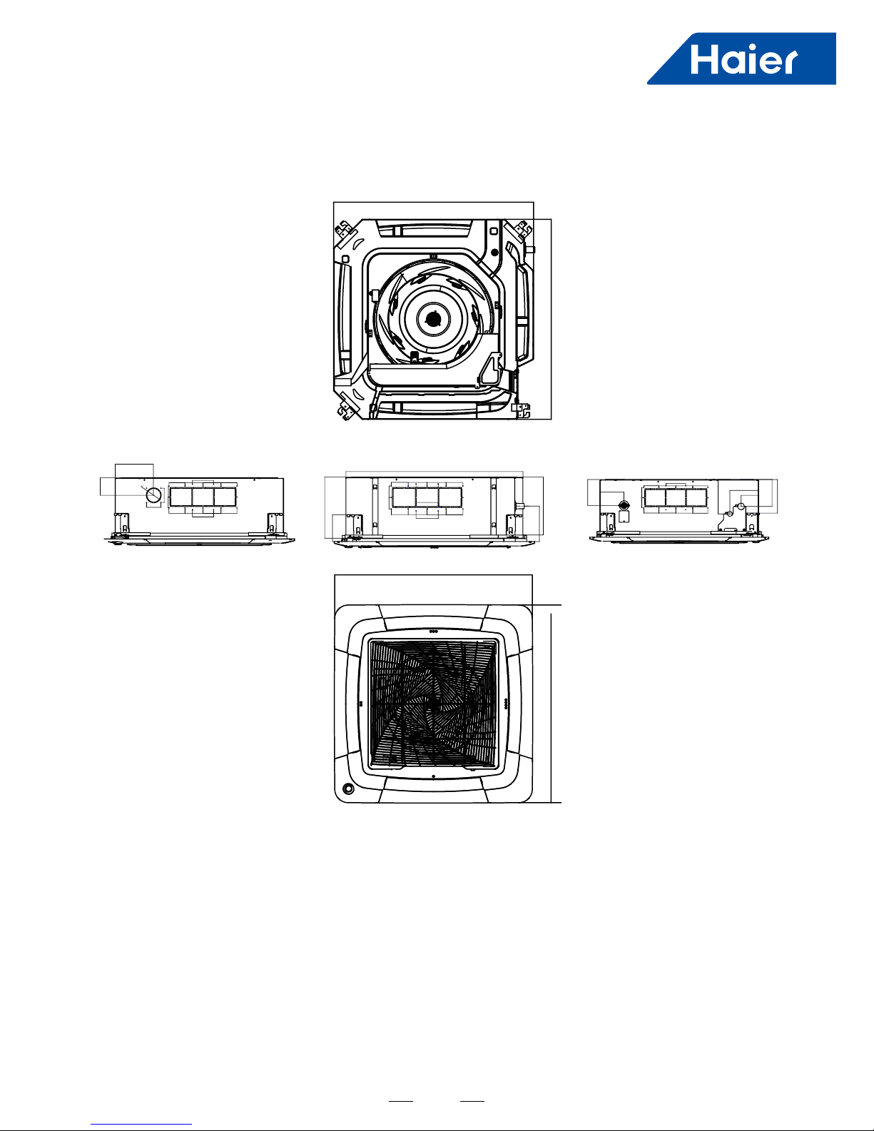
3. Dimension
AB25S2SC1FA AB35S2SC1FA AB50S2SC1FA
13
840
840
840
80
5454
80 90
950
950
90 80
168
275
105
288
80
90
90
105
80
80
90
90
80
90
54 54
71
71
191
191
75
128
90 90
105
105
80
128
80
80 80
54 54
90
90
90
105
90
80
183
143
178
152
93
138
AB71S2SG1FA
14
4. Wiring Diagram
AB25S2SC1FA AB35S2SC1FA
TO OUT DOOR
0150523323
BM1-1
BM1-7
BM1-8
TYPE DEFINE
OFFOFF
BM1-2 BM1-3
BTU
B:BLACK
R:RED
W:WHITE
Y/G:YELLOW/GREEN
TEMP.
SENSOR
ROOM
SENSOR
FLOAT
SWITCH
HEATER
PUMP
UP/DOWN
CN9
CN1
CN6
PANNEL
CN4
CN11
CN19
CN13
CN3
ON
CN7
CN21
T5A/250VAC
FUSE
BM3
2
1
3
B
W
R
Y/G
OFF OFF OFF
ON OFF OFF
OFF ON OFF
ON ON OFF
OFF OFF ON
ON OFF ON
OFF ON ON
ON ON ON
9000
12000
18000
24000
28000
36000
48000
60000
NOTE1.DASHED PART ARE OPTIONAL.
2. USER SHOULD NOT TO SET BM1 AND BM3
CH1
OFF OFF
BM1-4
BM1-5
BM1-6
OFF
OFF
CN16
G
CN8
G
TEMP.
PIPING
DC FAN
ROOMCARD
U-HOME
WIRED
CONTROLLER
B
A
C
BA
C
REMOTE
CENTRAL
87654321
ON
BM1
OFF
87654321
N
OFF
Room card
available
unavailable
ON
AB25S2SC1FA
AB35S2SC1FA
Default
15
TO OUT DOOR UNIT
SW1-1
TYPE DEFINE
Cassette
Y/G:YELLOW/GREEN
RD:RED WHT:WHITE
BLK:BLACK
******************
.
SENSOR
CN1
CN11
CN19
SW3(BM3)
2
1
3
BLK
WHT
RD
OFF OFF ON
9.0
10.5
NOTE:
1.DASHED PARTS ARE OPTIONAL.
2.USER SHOULD NOT CHANGE THE
DIP SWITCH SW1 SW3 WITHOUT GUIDENCE
3.SW3-5->SW3-8 ARE USED FOR WIRED CONTROLLER
ADRESS SELECT. SW3-1->SW3-4 ARE RESERVED.
CH1
OFF
OFF
TEMP
.
PIPING
DC FAN MOTOR
BA
C
87654321
SW1(BM1)
87654321
N
(SLIM)
Room card
available
ON
Y/G
0150527035
L
WiFi
MODULE
B
A
C
WIRED
CONTROLLER
M
SENSOR
TEMP.
ROOM
ROOM CARD
CN3
CN6
T5A 250VAC
CN16
DRAIN
PUMP
M
CN9
CN10
CN4
FUSE
FLOAT
SWITCH
CN13
INDOOR UNIT
MAIN CONTROL
BOARD
I.R .RECEIVER :
INFRARED REMOTE
RECEIVER .
TEMP.:TEMPERATURE
ON
OFF
ON
62NC
A
B
M
FRESH AIR MOTOR /
EXTERNAL ALARM OUTPUT
(FUNCTION IN FUTURE )
( Contact rating_230VAC,3A)
CAPACITY
(KW)
SW1-2
SW1-3
OFF ON
ON
OFF
ON
ON
12.5
ON
ON
ON
14.0
SW1-4
unavailable
OFF
ON
SW1-5
COOL HEAT
COOL ONLY
HEAT PUMP
SW1-6
SW1-7
SW1-8
OFF
OFF
ON
INDOOR UNIT
TERMINAL BLOCK
CN8
7.1
ON
ON
OFF
ELECTRIC HEATING TERMINAL
RATING_230VAC,3A
CONNECT TO THIRD PARTY RELAY
CN15
ELECTRIC HEATING
THERMOSTAT / FUSE
(INSIDE PANEL,
WITHOUT
DIGITAL
DISPALY)
INFRARED
REMOTE
RECEIVER
CN21
5.0
ON
OFF
OFF
ON
OFF
OFF
3.5
AB50S2SC1FA
16
TO OUT DOOR UNIT
SW1-1
TYPE DEFINE
Cassette
Y/G:YELLOW/GREEN
RD:RED WHT:WHITE
BLK:BLACK
******************
.
SENSOR
CN1
CN11
CN19
SW3(BM3)
2
1
3
BLK
WHT
RD
OFF OFF ON
9.0
10.5
NOTE:
1.DASHED PARTS ARE OPTIONAL.
2.USER SHOULD NOT CHANGE THE
DIP SWITCH SW1 SW3 WITHOUT GUIDENCE
3.SW3-5->SW3-8 ARE USED FOR WIRED CONTROLLER
ADRESS SELECT. SW3-1->SW3-4 ARE RESERVED.
CH1
OFF
OFF
TEMP
.
PIPING
DC FAN MOTOR
BA
C
87654321
SW1(BM1)
87654321
N
(SLIM)
Room card
available
ON
Y/G
0150527033
L
I.R .RECEIVER
(WITH DIGITAL
DISPLAY)
WiFi
MODULE
.
B
A
C
WIRED
CONTROLLER
M
SENSOR
TEMP
.
ROOM
ROOM CARD
CN3
CN6
T5A 250VAC
CN16
DRAIN
PUMP
M
CN9
CN10
CN4
CN14
FUSE
FLOAT
SWITCH
CN13
CN4
CN3
CN2
CN7
CN1
CN6
INTELLIGENT
MOVE EYE DEVICE
M
M
LOUVER
STEP MOTOR4
LOUVER
STEP MOTOR3
M
M
LOUVER STEP
MOTOR2
LOUVER STEP
MOTOR1
INDOOR UNIT
MAIN CONTROL
BOARD
I.R .RECEIVER :
INFRARED REMOTE
RECEIVER .
TEMP.: TEMPERATURE
ON
OFF
ON
62NC
A
B
M
FRESH AIR MOTOR /
EXTERNAL ALARM OUTPUT
(FUNCTION IN FUTURE )
( Contact rating_230VAC,3A)
CAPACITY
(KW)
SW1-2
SW1-3
OFF ON
ON
OFF
ON
ON
12.5
ON
ON
ON
14.0
SW1-4
unavailable
OFF
ON
SW1-5
COOL HEAT
COOL ONLY
HEAT PUMP
SW1-6
SW1-7
SW1-8
OFF
OFF
ON
INDOOR UNIT
TERMINAL BLOCK
CN8
7.1
ON
ON
OFF
ELECTRIC HEATING TERMINAL
RATING_230VAC,3A
CONNECT TO THIRD PARTY RELAY
CN15
ELECTRIC HEATING
THERMOSTAT / FUSE
AB71S2SG1FA
17
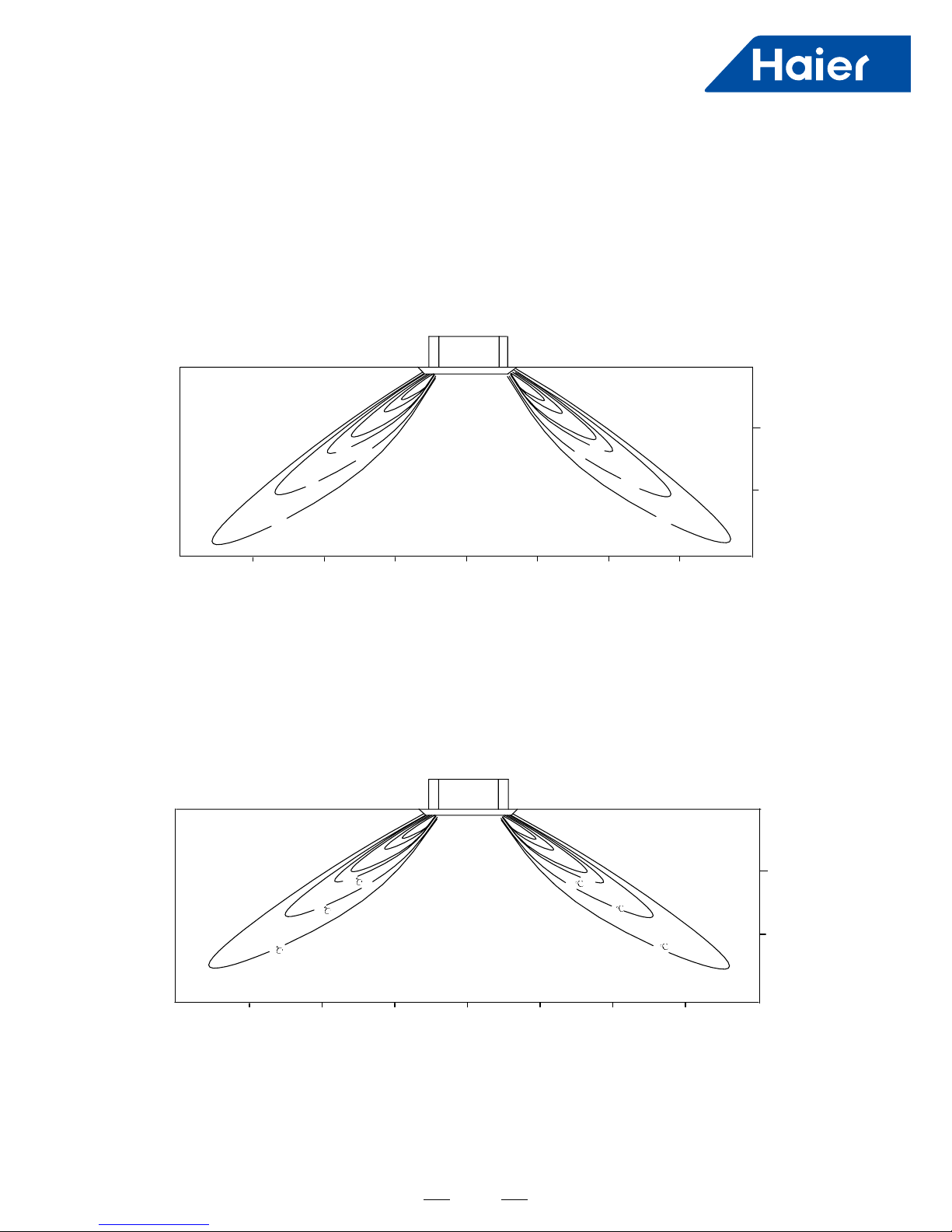
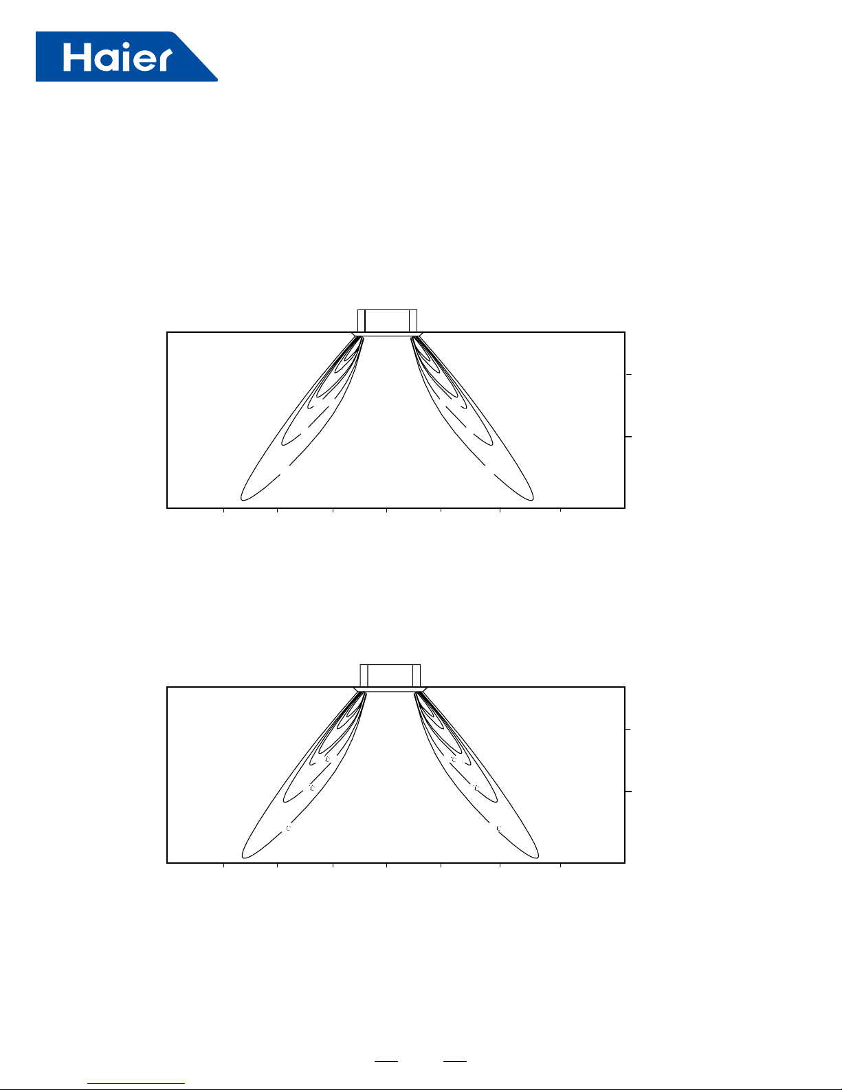
5. Air Velocity and Temperature Distribution
2m2m
1m
1m
4m
3m
3m
4m
0m
1.5m/s
1.5m/s
1.0m/s
1.0m/s
0.5m/s
2.7m
2m
1m
0m
0.5m/s
a. Cooling / air velocity distribution
Cooling
Blowy angle: 40
Air velocity distribution
b. Cooling / temperature distribution
Cooling
Blowy angle:4 0
Temperature distribution
2.7m
27
25
22
27
25
22
4m
3m
2m2m
1m
1m
3m
4m
0m
2m
1m
0m
AB25S2SC1FA AB35S2SC1FA AB50S2SC1FA AB71S2SG1FA
18
c. Heating / air velocity distribution
Heating
Blowy angle:70
Air velocity distribution
d.
Heating / temperature distribution
Heating
Blowy angle:70
Temper
Ature distribution
2.7m
2m
1m
0m
1.5m/s
1.5m/s
1.0m/s
1.0m/s
0.5m/s
2m2m
1m
1m 3m
3m
4m4m
0m
0.5m/s
22
27
25
22
25
27
2.7m
2m
1m
0m
2m2m
1m
1m 3m
3m
4m4m
0m

19
0.0
5.0
10.0
15.0
20.0
25.0
30.0
35.0
40.0
45.0
50.0
55.0
2
5.
0
3
1.
5
4
0.
0
5
0.
0
6
3.
0
8
0.
0
1
00
.0
1
25
.0
1
60
.0
2
00
.0
2
50
.0
3
15
.0
4
00
.0
5
00
.0
6
30
.0
8
00
1
.0
00
0
1
.
0
25
0
1
.
0
60
0
2
.
0
00
0
2
.
0
50
0
3
.
0
15
0
4
.
0
00
0
5
.
0
00
0
6
.
0
30
0
8
.
0
00
1
0
0
.
0
0
0
1
0
2
.0
5
00
1
6
.
0
0
0
2
0
0
.0
0
00
.0
Third octave band frequency Hz
Sound pressure level DB
cooling high
cooling med
cooling low
fan high
fan med
fan low
heating high
heating med
heating low
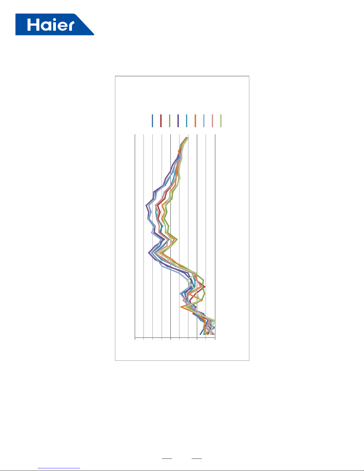
1/3 octave band noise level-AB50S2SC1FA
Third octave band frequency Hz
Noise level-AB24ES1ERA (S)
8
11
41
71
02
32
62
92
23
53
83
14
44
74
05
35
2
5
3
1.
5
4
0
5
0
6
3
8
0
1
00
1
25
1
60
2
00
2
50
3
15
4
00
5
00
6
30
8
00
1
00
0
1
25
0
1
60
0
2
00
0
2
50
0
3
15
0
4
00
0
5
00
0
6
30
0
8
00
0
1
00
00
1
25
1
00
60
00
0
2
00
00
Sound pressure level DB
wol gnitaeh
elddim gnitaeh
hgih gnitaeh
wol gnilooc
elddim gnilooc
hgih gnilooc
wol naf
elddim naf
hgih naf
6. Sound Pressure level
20
0.00
5.00
10.00
15.00
20.00
25.00
30.00
35.00
40.00
45.00
2
5
4
0
6
3
1
0
0
1
6
0
2
5
0
4
0
0
6
3
0
1
0
0
0
1
6
0
0
2
5
0
0
4
0
0
0
6
3
0
0
1
0
0
0
0
1
6
0
0
0
Third octave band frequency Hz
1/3 octave band noise level-AB71S2SG1FA
Fan-high
Fan-med
Fan-low
Coo ling-high
Coo ling-med
Coo ling-low
Hea ting-high
Hea ting-med
Hea ting-low
Sound pressure level DB
21
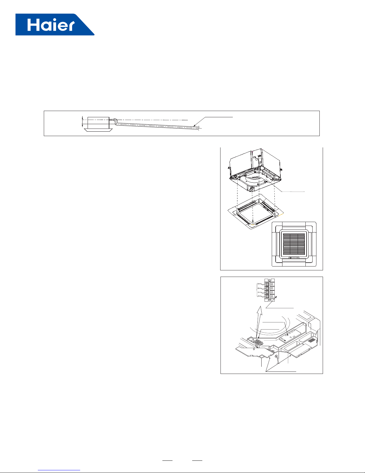
7. Installation
①
Before Installation
②
Selection Of Installation Place
<Don't discard any accessories until comp>
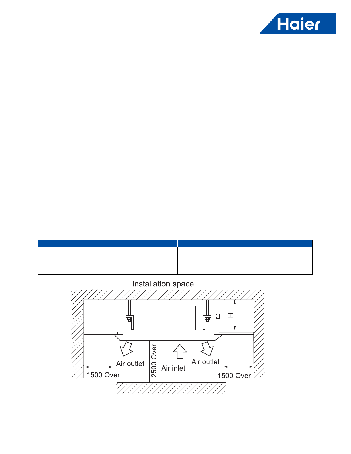
(1) Installation place shall meet the following and agreed by customers
(2) Ceiling height
Indoor unit can be installed on ceiling of 2.5-3m in height. (Refer to foeld setting and installation manual of
ornament panel.)
(3) Install suspending bolt.
Check if the installation place is strong enough to hold weight. Take necessary measures in case it is not safe.
(Distance between holes are marked on paper pattern. Refer to paper pattern for place need be reinforced)
• Determine the way tocarry unit toinstallation place.
• Don't remove packing until unit reaches installation place.
• If unpacking is unkavoidable, protect unit properly.
• Place where proper air ow can be ensured.
• Noblock toair ow.
• Water drainage is smpoth.
• Place strong enough to support unit weight.
• Place where inclination is not evident on ceiling.
• Enough space for mainenance.
• Indoor and outdoor unit piping length is within limit. (Refer to Installation Manual for outdoor unit.)
• Indoor and outdoor unit, power cable, inter unit cable are at least 1m away fromT.V. radop. This is helpful to avoid
picture disturbance and noise. (Even if 1m iskept, noise can still appear if radio wave is strong)
Model H
AB25S2SC1FA AB35S2SC1FA AB50S2SC1FA 320
AB25S2SC2FA AB35S2SC2FA AB50S2SC2FA 320
AB50S2SF1FA 236
AB71S2SG1FA 257
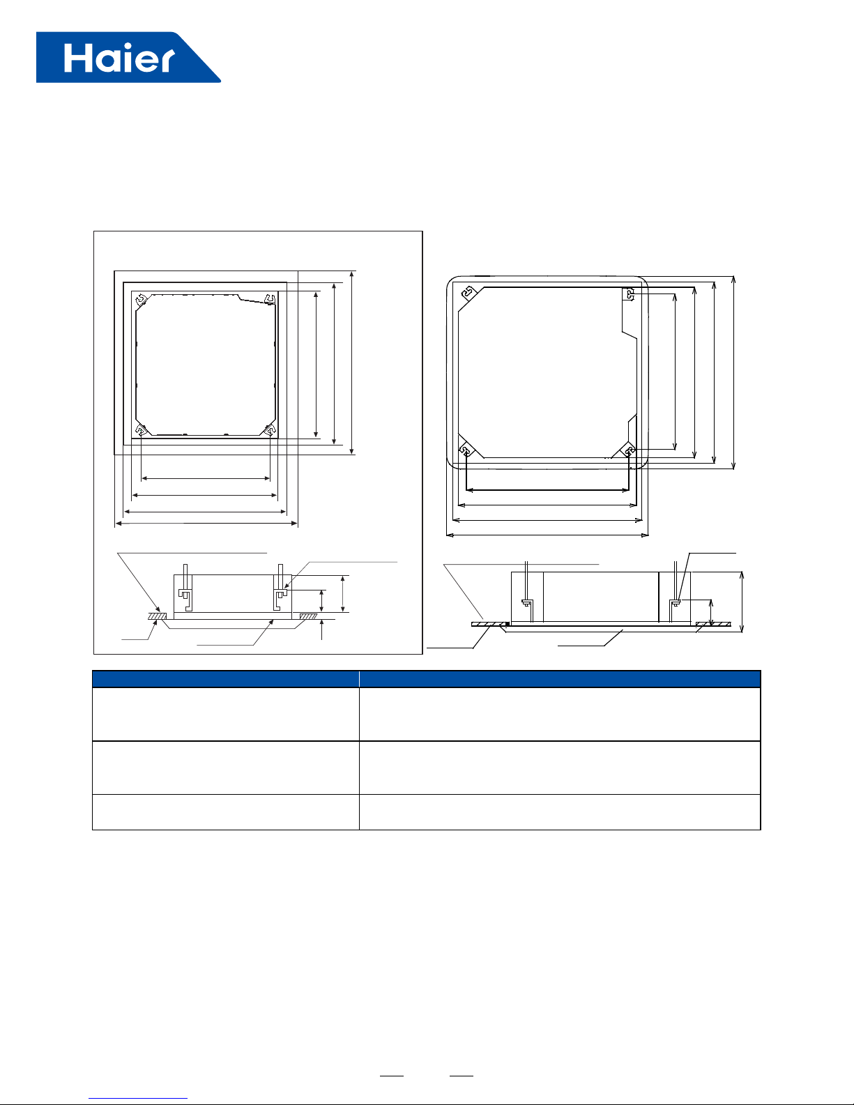
22
Indoor Unit Panel
AB25S2SC1FA
AB35S2SC1FA
AB50S2SC1FA
PB-700IB
AB25S2SC2FA
AB35S2SC2FA
AB50S2SC2FA
PB-620KB
AB50S2SF1FA
AB71S2SG1FA
PB-950KB
(2) Cut an opening in ceiling for installation if necessary. (When ceiling already exists.)
(3) Install a suspending bolt. (Use a M10 bolt)
• Refer to paper pattern for dimension of ceiling hole.
• Connect all pipings (Refrigerant, water drainage), wirings (Inter unit cable) to indoor unit, before installation.
• Cut a hole in ceiling, may be a frame should be used to ensure a smooth surface and to prevent vibration.
• Contact your real estate dealer
• To support the unit weight, anchor bolt shall be used in the case of already exists ceiling. For new ceiling, use
builtin type bolt or parts prepared in the eld.
• Before going on installing adjust space between ceiling.
Note: All the above mentioned parts shall be prepared in eld.
③
Preparation for the Installation
(1) Position of ceiling opening between unit and suspending bolt.
236
AB25S2SC1FA AB35S2SC1FA AB50S2SC1FA
AB50S2SF1FA AB71S2SG1FA
AB25S2SC2FA AB35S2SC2FA AB50S2SC2FA
Distance between
Distance between
Indoor unit 570mm
Ceiling opening 650mm
Ornament panel 700mm
Indoor unit 840mm
Ceiling opening 890mm
Ornament panel 950mm
suspending bolts 535mm
suspending bolts 765mm
Indoor unit 570mm
Indoor unit 840mm
Ceiling opening 650mm
Ceiling opening 890mm
Ornament panel 700mm
Ornament panel 950mm
Overlap between ceiling and
ornament panel shall be 25mm
Overlap between ceiling and
ornament panel shall be 25mm
Suspending bolts
Suspending bolts
Ceiling
Ceiling
Ornament panel
Ornament panel
150
130
260
30
Distance between sus
pending bolts 765mm
236
AB50S2SF1FA AB71S2SG1FA
Distance between
Indoor unit 840mm
Ceiling opening 890mm
Ornament panel 950mm
suspending bolts 765mm
Indoor unit 840mm
Ceiling opening 890mm
Ornament panel 950mm
Overlap between ceiling and
ornament panel shall be 25mm
Suspending bolts
Ceiling
Ornament panel
130
Distance between sus
pending bolts 765mm
23
(5) Remove the washer mounlting ② and tighten the
nut above.
(6) Remove the paper pattern.
④
Installation of Indoorunit
(1) Install unit temporally
Put suspending bracket on the suspending bolt.
Be sure to use nut and washer at both ends of the
bracket.
(2) As for the dimensions of ceiling hole, see paper
pattern. Ask your real estate dealer for details.
Center of the hole is marked on the paper pattern.
Center of the unit is marked on the card in the unit
and on the paper pattern.
Mount paper pattern ⑤ onto unit using 3 screws
⑥
Fix the corner of the drain pan at piping outlet.
In The Case of New Ceiling
<Aer Inslallalion on the Ceiling>
(3) Adjust unit to its right position.
(Refer to preparation for the installation-(1))
(4) Check units horizontal level.
Watert pump and ating switch is installed inside
indoor unit, check four corners of the unit for its level
using horizontal compartor or PVC tube with water. (If
unit is tilting against the direction of water drainage,
problem may occur on oating switch, causing water
leakage.)
Installation example
Roof
Anchor bolt
Long nut
Suspending bolt
Ceiling
Nut (Prepare in feild)
Washer (Prepared in feild)
Suspending bolts
Fasten (Double nuts)
Insert
Washer fixing pad
(Prepared in feild)
[Secure the washer firmly]
Polythene pipe
Screws at the piping outlet is
fixed at the cornerof drain pan.
Center of ceiling hole
Paper pattern
Screw (Accessory)
Paper pattern⑤
Screw (Accessory)
[Fix the paper pattern]
Level
24
In the Case of Ceiling Already Exisls
(1) Install unit temporally
Put suspending bracket on the suspending bolt.
Be sure touse nut and washer at both ends of the bracket. Fix the bracket rmly.
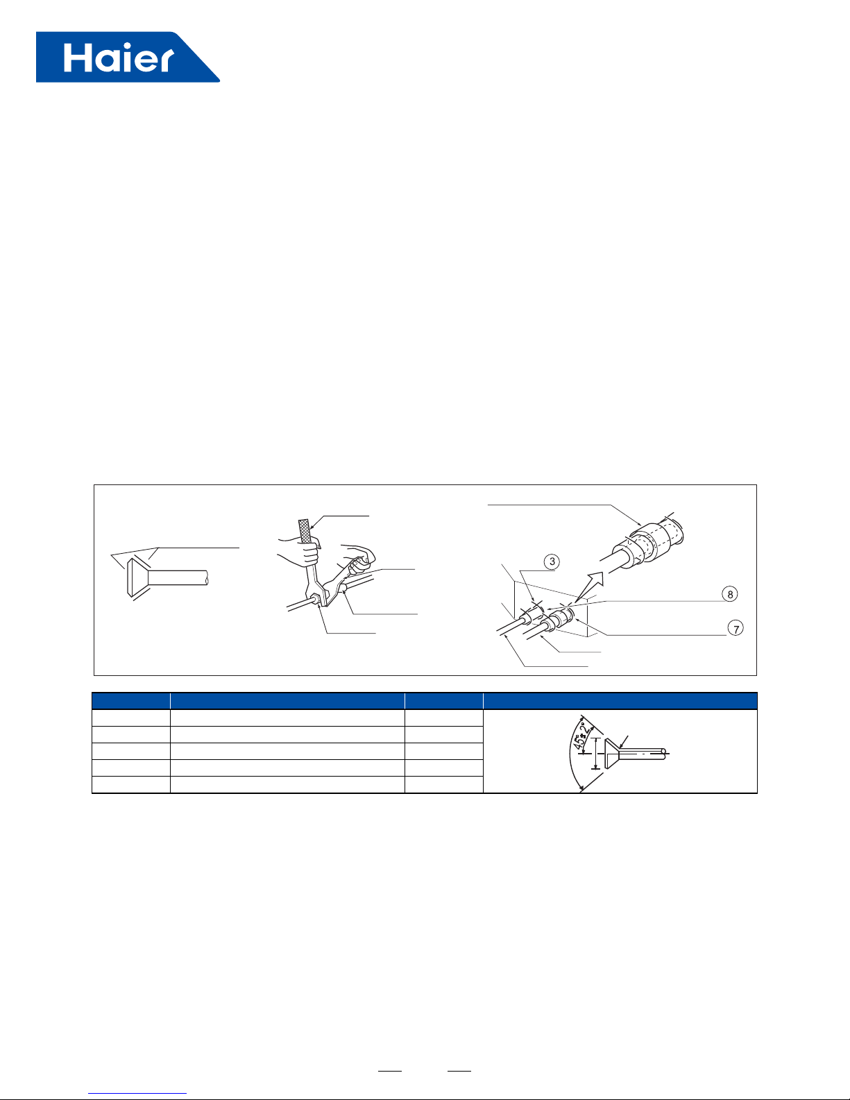
• Outdoor is precharged with refrigerant.
• Be sure tosee the Fig.1, when connecting and removing piping from unit.
• For the size of the are nut, please refer to Table 1.
• Apply refrigerant oil at both inside and outsid of lare nut. Tighten it band tight 3-4 turns then tighten it.
• Use torque specied in Table 1. (Too much force may damage are nut, causing gas leakage).
• Check piping joints for gas leakage. Insulate piping as shown in Fig. below.
• Cover joint of gas piping and insulator 7 with seal.
(2) Adjust the height and position of the unit. (Refer to preparation for the installation (1) ).
(3) Proceed with ③ and ④ of "In the case of new ceiling".
⑤
Refrigerant Piping (As for outdoor piping, please refer to installalion manual of outdoor unit.)
Apple refrigerant oil
Torque spanner
Medium size seal pad ⑪ (accessory)
Cover the piping joint
with seal pad)
Clamp
Liquid pipe
Gas pipe
Insulator (accessory)
(For liquid pipe)
Insulator (accessory)
For gas pipe
Spanner
Piping joing
Flare nut
Table 1
Pipe Size Tighten Torque A (mm) Flare Shape
φ6.35 1420-1720N.cm (144-176 kgf.cm) 8.3-8.7
9.52 3270-3990N.cm (333-407 kgf.cm) 12.0-12.4
12.7 4950-6030N.cm (490-500 kgf.cm) 12.4-16.6
15.88 6180-7540N.cm (630-770 kgf.cm) 18.6-19.0
19.05 9720-11860N.cm (990-1210 kgf.cm) 22.9-23.3
A
R0.4 - 0.8
90°±0.5°
25
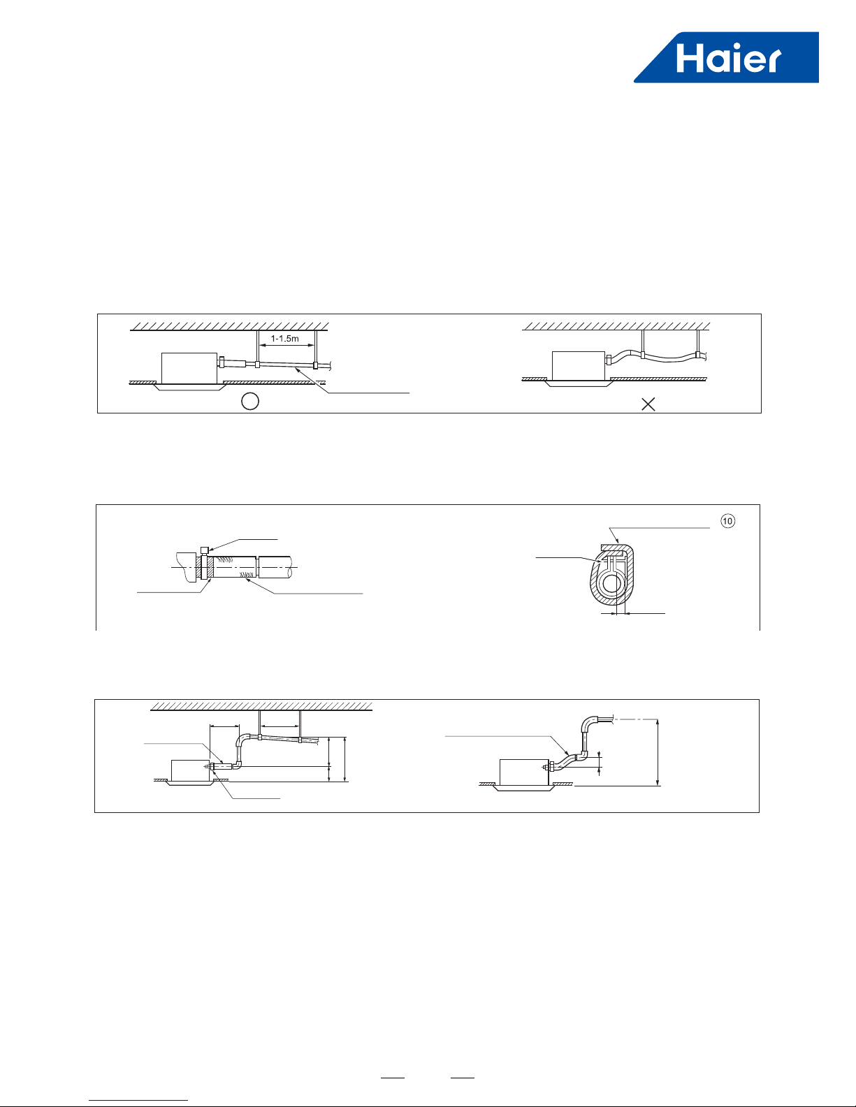
<Caulions for the Drain Waler Lifting Pipe >
Installation height shall be less than 280mm.
There should be a right angle with unit, 300mm from unit.
300mm below
1~1.5m
Clamp
(accessorry)
Drain hose
(accessory)
drain water lifting pipe
Suspending bracket
self-provided stiff pipe
75 below
500 below
(accessory)
220 280 below
500 below
⑥
Installation of Waterdrainage Pipe
(1) Install water drainage pipe
• Pipe dia, shall be equal or larger than that of unit piping. (Pipe of polyethylent; size 25mm; O.D 32mm)
• Drain pipe should be short, with a downward slope at least 1/100 toprevent air bag from happening.
• If downward slope can t be made, take other measures to lift it up.
• Keep a distance of 1-1.5m between suspending brackets, tomake water hose straight.
• Use the self-provided stiff pipe and clamp ① with unit. Insert water pipe into water plug until it reaches the white
tape. Tighten the clip until head of the screw is less than 4mm from hose.
• Wind the drain hose to the clip using seal pad ⑨ .
• Insulate drain hose in the room.
Apple refrigerant oil
Torque spanner
Medium size seal pad ⑪ (accessory)
Cover the piping joint
with seal pad)
Clamp
Liquid pipe
Gas pipe
Insulator (accessory)
(For liquid pipe)
Insulator (accessory)
For gas pipe
Spanner
Piping joing
Flare nut
Table 1
Apple refrigerant oil
Torque spanner
Medium size seal pad ⑪ (accessory)
Cover the piping joint
with seal pad)
Clamp
Liquid pipe
Gas pipe
Insulator (accessory)
(For liquid pipe)
Insulator (accessory)
For gas pipe
Tape (White)
Clamp
Self-provided stiff pipe
Clamp
Large size seal pad
(accessory)
4mm below
(accessory)
Spanner
Piping joing
Flare nut
Table 1
26
The slope of water drain hose (1) shall be within 75mm, don't apply too much force on it.
If several water hoses join together, do as per following proceedures.
Specieations of the water hoses shall meet the requirements for the unit running.
Note:
(2) Check if water drainage is smooth after installation.
• Check whether indoor unit is horizontal with leveler or polythene pipe
lled with water, and check that the dimension of the ceiling opening is
correct. Take off the lever gauge before install the ornament panel.
• Fasten the screws to make the height difference between the two
sides of indoor unit less than 5mm.
• First x it with screws temporally.
• Fasten the two temporally xing screws and other two, and tighten the
four screws.
• Connect the wires of synchro-motor.
• Connect the wire of signal.
• If no response of remote controller, check whether the wiring is
correct, restart remote controller 10 seconds after shut off power supply.
• Install the panel board in the direction shown in the gure. The
incorrect direction will result in water leakage, meanwhile swing and
signal receiving are displayed that cannot be connected.
• Charge, through air outlet or inspecting hole, 1200ccd water to see
water drainage.
• Check water drainage in cooling operation.
<Limits of Panel Board Installalion>
After Wiring
300mm below
1~1.5m
Clamp
(accessorry)
Over 100
Drain hose
(accessory)
drain water lifting pipe
Suspending bracket
self-provided stiff pipe
75 below
500 below
(accessory)
Connect water hoses
with at joint.
220 280 below
500 below
75 below
500 below
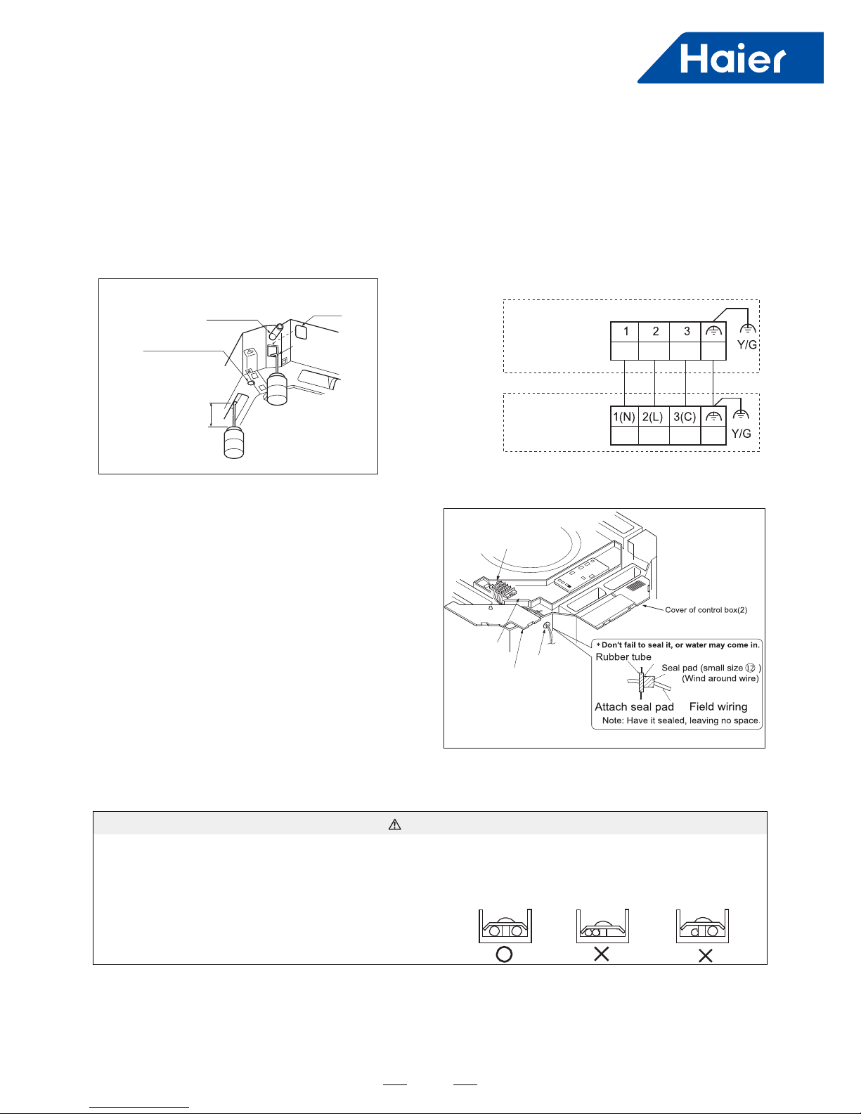
Electric control box
Connect with
outdoor unit
Terminal block
PCB on
indoor unit
Terminal block
Cover of controll box
27
⑦
WIRING
• All supplied parts. materials and wiring operation must in
appliance with local code and regulations.
• Use copper wire only.
• When make wiring, please refer towiring diagram also.
• All wiring work must be done by qualied electricians.
• A circuit breaker must be installed, which can cut power
• supply toall system.
• See Installation Manual of outdoor unit for specications
of wires, circuit breaker, switches and wiring etc.
• Connecting of unit
Remove cover of switch box (1), drag wires into rubber tube
A, then, after proper wiring with other wires, tighten clamp A.
Connect wires of correct pole to the terminal block inside.
Wind sea 12 around wires. (Be sure to do that, or, dew may
occur).
• Upon connecting, replace control box cover (1) and (2).
Obscrve the following when connecting power supply
terminal block.
Don't connect wires of different specications to the same
terminal block.
(Loose wire may cause overheating of circuit)
Connect wires of same specications as shown in right Fig.
Connect wires
of the same
specications
at twosides.
Don't connect
wires of the same
specications
at one side.
Don't connect
wires of the same
specications
at one side.
WARNING:
Terminal block
Grounding lead
Cover of control box(1)
In
Out
Rubber tube A
AB25S2SC1FA
Method of water charging
Self-provided stiff pipe
Water drainage port for
maintenance
(Drain water from
this hole)
100mm
Watering can of plastic
pipe should be about
100 mm long
Charge water from
inspecting hole
Charge water from
air outlet
Indoor unit
terminal block
Outdoor unit
terminal block
Maintenance
Inspecting hole
AB35S2SC1FA
AB50S2SC1FA
AB25S2SC2FA
AB35S2SC2FA
AB50S2SC2FA
AB50S2SF1FA
AB71S2SG1FA
300mm below
1~1.5m
Clamp
(accessorry)
Over 100
Drain hose
(accessory)
drain water lifting pipe
Suspending bracket
self-provided stiff pipe
75 below
500 below
(accessory)
Connect water hoses
with at joint.
Electric control box
Connect with
outdoor unit
Terminal block
PCB on
indoor unit
Terminal block
Cover of controll box
220 280 below
500 below
• Remove cover of control box, connect 1PH power to terminal 1 and 2 on terminal block. Use remote controller to
operate the unit.
• Note, in this operation, fan will be running.
• Upon conrmation of a smooth water drainage, be sure to cut off power supply.
When Wiring is not Complele
 Loading...