

Page 1

HAIER
COLOR TELEVISION
SERVICE MANUAL
PART # TV-8888-35
HAIER AMERICA TRADING, LLC
www.haieramerica.com
1
Page 2

Service Manual
46EP14S SERIES
PDP COLOUR TV
Main feacture
46 inch WXGA PDP Display Panel
DVI&PC Input Terminal (Including XGA&VGA)
PIP (Picture in Picture)
Multiple Signals Inputing
WOW Sound Processing System
Power Supply Managenent Function
Haier Group
NO: M-AM-US-P46C6A-A1-PW Edition:2004.2.30
Page 3

1.Contents
Contents
1.Contents
...............................................................................................................................................1
2.Product code illumination and Series Introduction.................................................2
3.FEATURES........................................................................................................................................3
4.Safety measures and Attention............................................................................................4
5. Photo of PDP taking apart:................................................................................................5
5.1 Photos of taking apart: .......................................................................................................5
5.2 Procedure:.................................................................................................................................5
5.3 Note:.............................................................................................................................................5
6. Introduction of PDP circuit board:.....................................................................................6
6.1 The introduction of circuit board at Back board:..................................................6
6.2 Explanation:(Function / Characteristic)..................................................................6
6.3 The block diagram:...............................................................................................................7
6.4 Function:....................................................................................................................................7
6.5 The definition of connector:.............................................................................................8
6.6 Detail Introduction of PDP circuit boards.................................................................9
7.Abnormal Phenomena:............................................................................................................13
8. Short Repair Show:..................................................................................................................14
9. Principle Flow-chart:................................................................................................................17
10. Bom list:.........................................................................................................................................18
11. Repair Record:..........................................................................................................................24
11.1 Record sheet: For reference............................................................................24
1
Page 4

Product MATERIAL CODE illumination and Series
2.Product code illumination and Series Introduction
46 C 6A– A 1
P
Aspect ratio: 16:9
Company of Signal processor IC A: Pixel works
Model series number of the cabinet
Manufacturer of the display panel C: CPT
Screen size (unit: inch)
Type of the display panel P: PDP
2
Page 5

Features
3.FEATURES
The 46” PDP provides quality image displays and is suitable for a variety of
multimedia applications.
a. Available Input signals:
The standard PC module provides RGB (D-SUB15 PIN) and digital DVI input
connectors, and a RS-232 communication connector (D-SUB 9 PIN MALE).
The Video module provides composite video (RCA), S-video (DIN4P) and
component video (RCA) input connectors, and a composite video (BNC)
output connector. It supports the quality input image of DVD and HDTV
(480P/720P/1080i). The video module also provides two sets of stereo audio
input connectors (RCA).
The product supports PC image resolutions up to XGA (1024х768) with a
vertical frequency of 85HZ.
b. Power Management Function: The machine provides an automatic power control
function.
c. Fan-free Design: The unit does not require any fans for ventilation, eliminating
any bothersome noise that may be generated. It also lowers the power
consumption of the unit.
d. Others:
PIP Function: Allowing user to video TV or video in PC module.
The product includes a set of build-in 2W+2W speakers, External 10W+10W
speakers are also available.
The plasma unit provides high, medium and low color temperature
adjustment options.
3
Page 6

Safety measures and Attention
4.Safety measures and Attention
4.1. Observation and measures carefully:
When in repair service, should pay attention to these safety measures and the
description
of the service menu.
4.2.Preparation:
The preparation for repair in a defective PDP is necessary, ex:stable working
table, repair tools, measuring equipments, replace parts etc.
4.3.Pay attention to electrical shock:
Because the PDP is using the AC power source, and the power board contents
high voltage, so to preventing the high voltage shock is necessary. Such as,
using an isolated transformer, plastic glove, charged components should be
discharged first. The high voltage is supplied to inferior components, so when
repair the PDP should pay more attentions.
4.4.Using the specified components:
Some components provide fire-resist and endure high-voltage. So when replace
these parts, should use the same characteristic components. So when replace a
component should according to the BOM form for a assigned component.
4.5.Stable the components and recovery the wiring:
Some components are using isolated sleeve or adhesive tape to isolate from the
electric board. Moreover the interior wiring should be arranged again to prevent
the interference from given out heat components and high voltage
components .So after repairing, should recover the same layout of the PDP.
4.6.Integrity of the electric circuit :
Use the specified components to replace the defective parts. Under any
circumstance,do not try to modified the electric circuit .
4.7.Safety check after repairing:
After repairing, should check the screws and the wiring condition. Checking the
quality of repairing components. The insulation test of the metal component,
power cord to make sure the safety of repairing.
4
Page 7
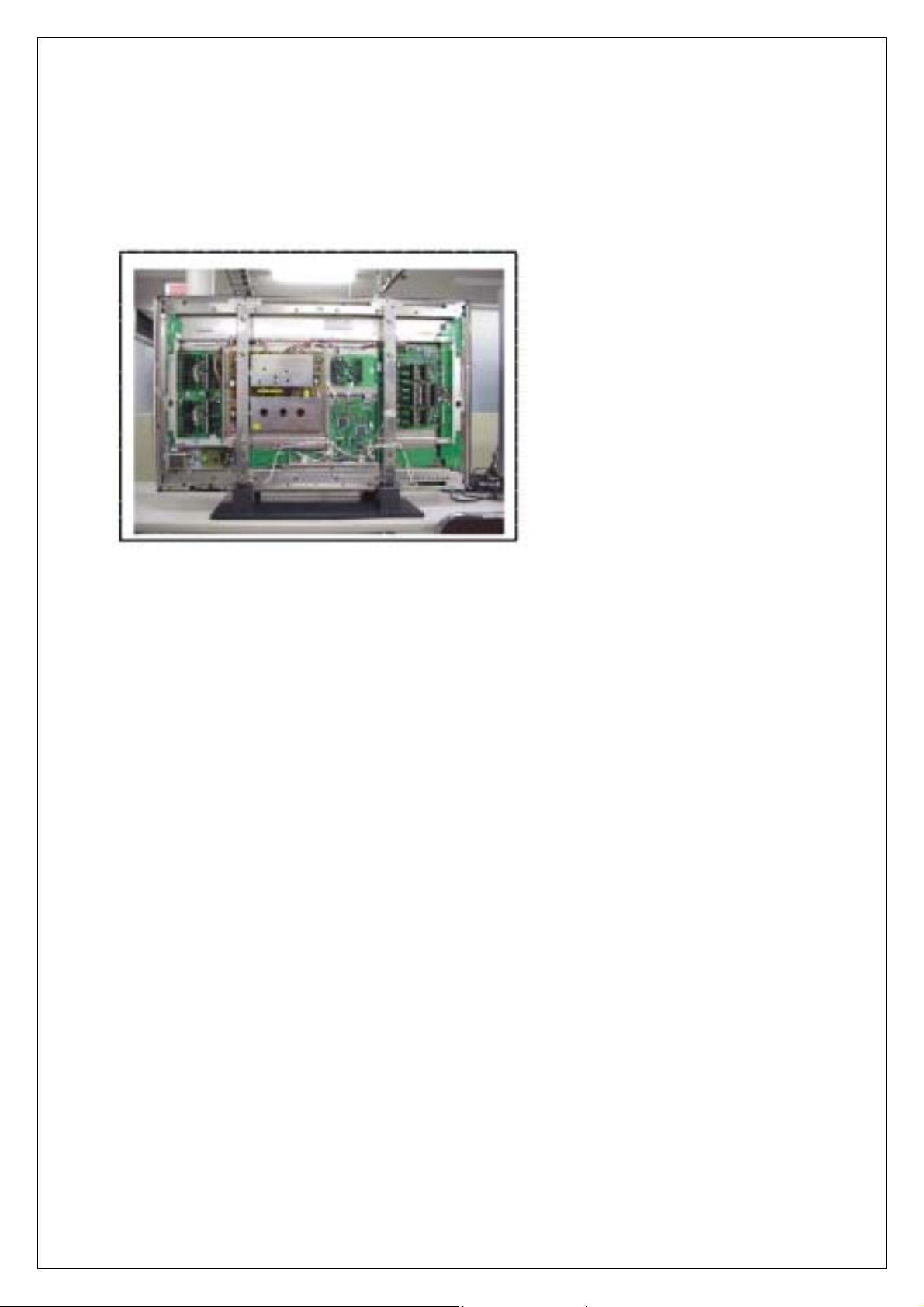
5. Photo of PDP taking apart:
5.1 Photos of taking apart:
Photo of PDP taking apart
5.2 Procedure:
1. First put on the PDP on a stable working table and power off the PDP which is
going to repair, then using a screwdriver to unfasten the screws which fasten
the back cover.
2. after taking apart as Fig. 2 shown.
5.3 Note:
1.Make sure that the power is off before taking apart .
2.After taking apart , put the screws at a safe place to avoid losing
3.Taking apart and installing the back cover , be careful not to pull out the switch of
AC power switch .
5
Page 8

Introduction of PDP Circiut board
6. Introduction of PDP circuit board:
6.1 The introduction of circuit board at Back board:
6.2 Explanation:(Function / Characteristic)
a. POWER: (1).Input Voltage (AC 110V-240V、47Hz-63Hz),Max. range
90V-265V.
(2).Providing electrical power to all the PCB.
b. VIF:Transfer S-video , Video , PC(D-sub& DVI) , HDTV signal to digital
signal to the DIF board.
c. DIF:Dealing with the digital signal for output to panel.
d. X-Sustainer / Y-Sustainer:(1).Receiving the signal from DIF.
(2). Output scanning waveform.
e. X / Y-Extension board: Receive signal from X / Y sustainer , output
horizontal scanning waveform to the panel.
f. W-Extension board: Receive signal from DIF , output the vertical scanning
waveform , addressing data.
g. Audio Board:Amplifying the audio signal to the internal or external
speakers of which select.
h. AC Line Filter:AC power line filter。
6
Page 9

6.3 The block diagram:
Introduction of PDP Circiut board
6.4 Function:
a. The input voltage AC 90 ~ 240 through line filter to the power board , after main
switch is on then power board generate 5 volts to VIF board. The VIF board after
receiving 5 volts then from CN connector send signal(5 volts) to power
board .Power board generates 5 volts to DIF and VIF .When VIF receives the 5
volts ,then generates 5 volts to power board through CN connector(pin1 ,pin6) ,
and it means that DIF has received 5 volts already.
b. When power on(key-pad or receiver),the VIF send VCC_ON signal to power to
start Vcc and Vf voltage through CN connector(pin2).
c. The VIF sends HV_ON signal to power board to start high voltage Vs , Vxg , Vw
through CN connector(pin4).
d. At the same time the signal from VIF to DIF for signal processing , then through X
/ Y / W board to start the screen.
7
Page 10

Introduction of PDP Circiut
6.5 The definition of connector:
⑴ PY POWER TO Y-SUSTAINER
Pin 1 2 3 4 5 6 7 8 9
Name GND Vcc GND Vf Vw GND GND NC Vs
Voltage O 5V O 15V 65V 0 0 --- 170V
⑵ PX1 POWER TO X-SUSTAINER
Pin 1 2 3 4 5 6 7
Name GND Vf Vw GND GND NC Vs
Voltage 0 15V 65V 0 0 --- 170V
⑶ PX2 POWER TO X-SUSTAINER
Pin 1 2 3 4 5
Name Vxg NC GND GND VAU
Voltage -160V --- 0 0 15V
⑷ J12 PC1 TO KEY PAD
Pin 1 2 3 4 5 6 7 8
Name Power Right Left Up Down Menu Input GND
⑸ J11 PC1 TO 接收板
Pin 1 2 3 4 5 6
Name NC Red-LED Green-LED GND IR Receiver 5V
⑹ J17 PC1 TO AUDIO AMP
Pin 1 2 3 4 5 6
Name MUTE L-OUT GND R-OUT GND SW-SPEAKER
⑺ J16 PC1 TO POWER
Pin 1 2 3 4 5 6 7 8 9 10
Name Std-5V Low-on NC High-on NC GND ---
Power
loss
-- GND
⑻ J15 PC1 TO POWER
Pin 1 2 3 4 5 6 7 8 9
Name 9V 9V GND GND Vcc 5V Vcc 5V GND GND Std-5V
8
Page 11

Introduction of PDP Circiut
6.6 Detail Introduction of PDP circuit boards
6.6.1 VIF Board:
a. Summary:
General digital video signals include Vsync、Hsync、R(8Bit)、G(8Bit)、B(8Bit) and Data
Enable (Blank);the VIF of PDP is making for processing these digital signal.
Because PDP belonging a high end product , so its application should include the
functions of Monitor (analog VGA , digital DVI signal input). And for consumer’s
sake , the VIF should have the functions of video , like audio , composite , s-video ,
component signal processing.
Below is the explanation of VIF system:
b. The role of VIF:
UHF/VHF TV
Cable TV
HDTV
VTR
DVD Player
PC
Home Video
Currently the video signal sources are video cassette recorder , DVD player , CATV ,
RF tuner , VGA card(PC). In order that all the video signal sources can be displayed
on PDP , so we need a interface to transfer these signals to a specified signals for
PDP to display , and this is the function of VIF(Video Interface).
Game
VIF
DIF
c. Basic framework of VIF board
For dealing with the signals of CVBS, S-video and Component, it requires a video
decoder IC. And the output of video decoder will input to a de-interlace chip IC for a
stable image quality. Because the TV system uses interlace scanning, it causes
flickers on the screen . To improve this situation so we use a de-interlace chip IC.
The ADC(Analog to Digital Converter) IC converts the analog RGB signal to digital
RGB signal. The TMDS(Transition Minimized Differential Signaling) decoder IC
transmits digital RGB signal. All the output of ICs’ signal send to scalar IC. The
relationship is shown as below, and make a brief explanation of the system.
9
Page 12

D-SUB
ADC
Converter
DVI
TMDS
Receiver
Y/Cb/Cr
S-Video
Composite
DeInterlace
Video
Decoder
c-1. ADC Converter:AD9888
The AD9888 is a complete 8 bit , 205 MSPS monolithic analog interface
optimized for capturing RGB graphics signals. Its 205 MSPS encode rate
capability and full-power analog bandwidth of 500 MHz supports resolutions up
to UXGA(1600 x1200 @ 75 Hz).
c-2 TMDS Receiver: SIL153BCT100
The Sil153BCT100 receiver uses Panel Link Digital technology to support high
resolution displays up to SXGA (25MHz~112MHz). The Sil153B receiver
supports up to true color panels (24 bit/pixel, 16.7M colors) in 1 or 2 pixels/clock
mode. In addition, the receiver data output is time staggered to reduce ground
bounce that affects EMI.
c-3 VIDEO Decoder:SAA7118E
The SAA7118E decoder is a ADC too, but it can deal with the ordinary TV
signals. The SAA7118E can input Composite (fig.A)、S-video (fig.B)、Component
(fig.C) and its outputs are digital Y(Luminance) , C (Chromacity) signals. And
also can adjust brightness, contrast, saturation, hue.
c-4 De-interlace:SIL504CM208
The Sil504 transfer interlacing signals to progressive signals. The advantage of
progressive signals is that the scanning rate doubling to let the screen more
stable and non-flickering. Besides, the sources of input may have 24 0r 30 or 25
frames per sec, so the de-interlaced chip shall tell from the differences and
processing the signals. The basic principle of de-interlaced IC is combined the
odd and even fields to a frame, and the processing needs a memory IC(SDRAM)
to stock these signals for processing . For the improving the quality of image
sake, more and more TVs or DVD players all have the functions of progressive
scanning.
Scalar
Chip
MicroController
Introduction of PDP Circiut
Out to DIF
10
Page 13

Introduction of PDP Circiut
c-5 Image Processor chip:PW171-20U(system on chip)
◎ Scaling function :
The Image scalars provide high quality up and down image scaling. For the
applications of VIF, the input signals could be VGA, SVGA, XGA formats, and its
output fixed at 852 x 480 @60 HZ. For example , SVGA format:800 x 600
@75Hz , first scaling down : Horizontal 800 640、Vertical 600 480 , 75 frames /
sec after frame rate conversion become 60 frames per sec. Then scaling up 640
852 , to accomplish the scaling function.
◎ Micro Processor Function :
This chip includes microprocessor (on-chip 80x86); selectable function and I/O
interface control. With 3 groups of 8-bit programmable I/O, 1 group of RS-232
communication port, IR decoder, timer and a PWM generator
◎ OSD Function:
The on-screen-display (OSD) can be used for startup screens, menus , and scribble
functions.
d. VIF (Video interface) :
d-1. When main switch is ON , the power board generates Vsby 5 volts to VIF
board. The IC of microprocessor become standby status waiting for a
startup signal from key-pad or receiver.
d-2 When a startup signal is detected then microprocessor sending a ON signal
to the power board through CN connector , and the power board begins
generating all voltage to PCB board(Vs, Vxg, Vw, Vf, Vdd, Vcc, 9volts) . At
the same time VIF will generate background light and OSD menu as select.
After searching a input source , then will display on the PDP screen , if there
are audio signals , it will amplify and send to speakers through audio board.
d-3 If there are abnormal signals are detected(such as over voltage , over
current , low voltage ..) , the power board will send abnormal detective
signal to shut down all the system
6.6.2 DIF Board:
Function:
The video or pc signal is processed and send to DIF form VIF.There are gamma
correction,basic white balance data,power loss control,and data translation function.
When DIF board work normally the LED on the board should light.when you turn on
the main power switch this LED should light a few seconds to inspect itself and then
disappear.
11
Page 14

Introduction of PDP Circiut
6.6.3 X/Y Sustainer Board:
Function: Receive the signal from DIF.And output high voltage scan signal to
panel.
6.6.4 Audio Amplifier Board:
Function:It comprises special swith mode power supply and audio amplifier and
electronic swith for outer and inner speakers exchange.
It connects to 300V from main power supply on the module from socket CN5601.
M5502 connects to inner speakers by cable.
M5503 connects to outer speakers socket boards by cable.
M5501 connects to VIF and receives the R,L audio signal,MUTE,SWITCH control
signal.
The inner output power is up to 4w.And the outer ouput power is up to 20w together
on 4ohm impedance.
12
Page 15

7.Abnormal Phenomena:
7.1 VIF board:
a. colour absence or colour step not good.
b. No sound from the speakers,but there was noise output.
c. Power supply is normal,there were OSD and backgroud light on the
panel,but not picture.
d. Can not turn on the set(LEDs do not work ).
e. There are some strip disturbance in the picture.
f. Turn off automatically after the set works a few minutes.
g. Picture wobbles when input 1080i signal.
7.2 DIF board
a. picture abnormal.
b. Can not turn on the set(LEDs do not work ).
7.3 Power Supply:
a. no picture output.
b. Output voltage abnormal
7.4 X scan sustainer:
h. no picture.
i. Colour of the picture is not enough.
j. Picture abnormal such as picture flicker
k. Can not turn on the set(LEDs do not work )
7.5.Y Bulk Sustainer:
a. Can not turn on the set. If disconnect the cable from power supply to Y
sustainer the set works,but the picture is dark. It means that Y sustainer is
abnormal.
b. Power output voltage is normal,but the picture is dark.
c. When the set works normally,the temperature of the compoenents on the
sustainer boards is about 55.If the temperature is over 55 ℃ there may
be some fault on there.
7.6 Audio Amplifier Board:
a. there is no sound or noise in the speakers.
b. Too much noise in the speakers.
c. Can not switch inner and outer speakers.
7.7 X Connecting Board(upper and lower parts)
Abnormal Phenomena
bright
black
7.8 Y Connecting Board(upper and lower parts)
bright
dark
13
bright
Page 16

p
N
N
r
Short Repair Show
8. Short Repair Show:
8.1 No picture and Red LED does not light, please make sure the main power swith
on and to check the fuses on the power supply board and power filtering board.
8.2 Turn on the main power switch, the green LED lights. But there was no picture.
Please check VIF or DIF or X sustainer or Y sustainer. You may exchange them
one by one with good boards.
Replace VIF , then turn on the switch, remote the set. If there are OSD,there is
some fault in the VIF.
8.3 If the picture is vague, please replace the Y-sustainer board.
8.4 The picture is separated into upper & lower parts, one part has picture, the other
has no, and the picture is from left to right, please check the X connecter board and
the X-sustainer board.
8.5 If the picture is vague or the picture of the upper or the lower part is dark, please
check the Y connecter board and the Y-sustainer board.
8.6 Please check whether the corresponding W board and the connect cords are in
good condition, otherwise , the module is iffy.
ormal picture
Dark vertical bar or stra
8.7 Please check whether the left (sight from the rear) Y connector board and the
connect cords are in good condition, otherwise , the module is iffy.
ormal picture
Dark horizontal bar o
8.8 If the chroma of the white signal isn’t uniform, please adjust the Vs 、VXG voltage
according to the voltage data of the PDP module.
14
Page 17

Short Repair Show
Vs VCC Vf
Vxg
VSTB
Vw
VAU
8.9 If many details of the picture are short of, or the pixels of the picture are not
discontiguous, the Pixel works IC doesn’t weld well, please replace the PC1 board.
8.10 Trouble of the DIF and the W connect cords or the connect jack.
8.11 There are many dark 、flicking、bright dot defect or a single or multi pieces of
line always appear in the screen, please replace the PDP module.
15
Page 18
Short Repair Show
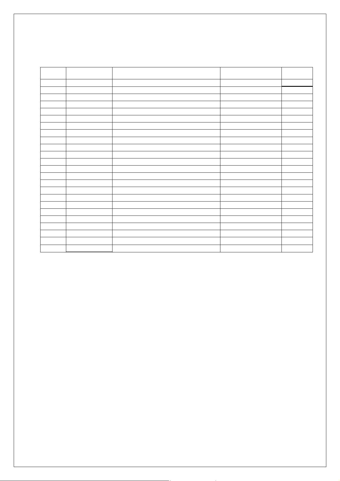
8.12 Inspection:
PDP SET inspection items after finishing repair :
Item Classified Inspection item Method Remark
1
2
3
4
5
6
7
8
9
10
11
12
13
14
15
16
17
18
19
20
21
22
23
24
Appearance Back cover screw shortage
Appearance Screen Filter scratch
Appearance Terminal loosing
Reliability voltage / frequency variation POWER SUPPLY
Reliability Hi-pot test Hi-pot tester
Reliability AC-INLET hi-pot test Hi-pot tester
Screen Position /Width
Screen H/V resolution / saturation
Screen H/V stability
Screen Hue / Color
OSD AUDIO-Mute/ Balance Eye view/remote
OSD INPUT-PC1 / HDTV / AV1 / AV2 Eye view/remote
OSD VIDEO-Color Temp / Gamma Eye view/remote
OSD VIDEO-Brightness / Contrast Eye view/remote
OSD FUNCTION-Information / Default Eye view/remote
OSD DISPLAY-Aspect Ratio / Zoom Eye view/remote
Signal/terminal Factory default / key-pad functio n Eye view
Signal/terminal PC TIMING/ TUNNER Eye view
Signal/terminal
Signal/terminal AV / S-video Eye view
Signal/terminal VIDEO / Component / PC AUDIO Eye view
Signal/terminal D-SUB/ DVI-I / RS-232 Eye view
characteristic
characteristic
White balance(△x) / (△y) / (△Y) / contrast
D-sub / DVI
Power consumption Power meter
Eye view
Eye view
Eye view
Eye view
Eye view
Eye view
Eye view
Eye view
CA-100
Optional
Optional
Optional
Optional
16
Page 19

9. Principle Flow-chart:
Principle Flow-chart
J15
WOW-EN-5
U32
J17
J16
J7
U31
J12
U23
RN51
RN52
J1N
3.3V
1,9,17,26,32,34,44
IC1N
RN50 RN47
WOW-EN-5V
HV-ON-5V
RST-DVDO-5V
SPK-SW-5V
BUFFER/LINE DRV
RN48RN49
SPK-SW
RST-DVDO5V
PWR-ON
HV-ON
MUTE-5V
WOW-EN
U19
RN33
RN31 RN27
RN34
RN32
VR0-7
VG0-7
FROM PW171
Y3
CRYSTAL
U17
Y2
CRYSTAL
U16
ADRESS1-19
DATA0-15
CS2n
CS0n
U15
U25
U11
J9
PARALLEL
U21
R122
R124
R123
R121
RN53
RN54
RN57
RN58
RN55
MUTE
RN29
VB0-7
RN56
PWR-ON
VS-OUTPUT
BLANK-OUT
CLK-OUTPUT
HS-OUTPUT
DOBLU0-7
DOGRN0-7
DORED0-7
U20
U18
12 BIT ADR
OSC
OSC
15
16
R12A
OTHER
5
SDA-5V
SCL-5V
SCART-MOD
R9A
SCART-RGB
(VIDEO)
(DVD)
(TV)
9V
L12
R11
R13
L13
R12
VCLK
VHS
VVS
L11
9V
9V
39b
73 65
4957
40b
J1
5V
ODD/EVEN OUTPUUT
RESET
BURST BACK PORCH
U7
WINBOND
MCU
U3
4053D
SWITCH
CT
9V
9V
GND
TV-CVBS
GND
TV-AR
GND
TV-AL
GND
SCL
SDA
GND
(CVBS-IN)
C7D
(VIDEO)
OUT1L
OUT1R
U2C
LM1117
3.3V
U1C
LM1117
2.5V
U2D
GND SW2
JRC
OUT
NJM2244
3 INPUT
5V
VIDEO
IN3
SWITCH
U1D
IN1
JRC
GND
NJM2267
2/VIDEO
6dB
AMPLIFIER
NTSC
R20C
R21C
2.5V
C29C
88
93
92
84
IN
OUT
GND
IN
OUT
GND
(GND)
IN2
(VIDEO)
SW1
(TV-CVBS)
IN2
5V
OUT2L
OUT2R
83
U3C
NEC
uPD64083GF
3D-COMB
383231
46
PAL
2.5V
3.3V 2.5V
OUT
IN
U4
U15
COMPOSITE SYNC OUTPUT
LM1881M
CVBS INPUT
SYNC
V-SYNC OUTPUT
SEPERATE
U13
TDA9874AH
NICAM DECODER
GND
U12
24C08
EEPROM
25
24
23
22
21
15
14
13
12
39a
40a
5V5V5VS
2.5V
81
64
2.5V
C12C
C1C
C-3D TV-CVBS
Y-3D
41 33 25
76 68 60 52 44 36 28 20
VIDEO-DET
RGB SW
SDA
SCL
PC-DET
B-PB
R-PR
AV-SW
HSYNC1
VSYNC1
G-Y
3.3V 3.3VA
3.3V 3.3V
S-VIDEO-Y
VIDEO IN
Y-3D IN
S-VIDEO-C
PAL CVBS-IN
U1B
3D-C IN
DVD-Y
DVD-Pb
DVD-Pr
XTAL
XTAL1
SDA
SCL
R13A
480P
24
4
IC1A
25
5VS
R16A
480I
27
41
DVI-EN
R14A
28
40
V-CLK
1b
17
9
1
2b
1a
12
4
2
2a
V-VS SCARTV-HS SCART
DVDO-EN-5V
TO SII504
DATA0-7
RP6B
RP4B
RP3B
RP5B
DATA
OUT
RP2B
DATA
RP1B
OUT
DATA
OUT
C24
C22
C27
R8B
V-CLK
XCLK
C25
V-HS
XRH
R9B
V-VS
XRV
R10B
C28
IGPH VHS
R5B
IGPV VVS
R6B
R25
DVDO-EN
ITRI
R11B
R24
U12
32 BIT DATA
RN28
RN30
DATA0-7
FROM
SAA7118
5V
15
28
21
20
U33
SDA
14
1
DVISDA
DVISCL
SCL
U6
U7
IN
U1C
U8
GRO0-7
GRE0-7
RN2
RN4
RN1
RN3
110
120
113
97
RN6
RAIN0
5
RAIN1
8
GAIN0
12
GAIN0
13
GAIN1
16
GAIN1
17
BAIN0
20
BAIN1
23
SDA
31
SCL
32
BAIN0
BAIN0
BAIN0
BAIN0
R22
R23
GGE0-7
RN5
U3
90
87
RN8
GGO0-7
RN7
80
77
RN10
GBE0-7
RN9
70
57
64
444342 45
RN12
RN11
GBO0-7
C23
C19
C18
U10 U4001
GND
GND
OUT
GNDINOUT
U4
LM1117
3.3V
LM1117
3.3V
RN34
GBO0-7
RN19
RN20
RN21
GGO0-7
RN22
RN23
GRO0-7
RN24
IN
LM1117
LM1117
OUT
OUT
U5
3.3V
3.3V
IN
GND
GRE0-7
GPEN
GVS
GHS
GCLK
RN17
RN18
RN15
GGE0-7
RN16
U9
RN13
GBE0-7
RN14
U1
J11
U2
TV SIGNAL
17
Page 20

Repair Record
11. Repair Record:
11.1 Record sheet: For reference
Item Repair
date
Defective
description
Repair condition Replace parts Finished
date
1
2
3
4
5
6
7
8
9
10
11
12
13
14
15
16
17
18
19
20
21
22
23
24
Signature
24
Page 21

Haier Group
Tel:86-532-8939999
Web side:http://www.haier.com
25
 Loading...