

Page 1

SYJS-04-2017 REV.A Edition: 2017-04
service manual
R32
Page 2

CONTENTS
Part 1 General Information .......................................................................................................................................1
1. Indoor/outdoor unit models................................................................................................................................2
2. Feature .................................................................................................................................................................3
Part 2 Indoor Units ....................................................................................................................................................5
1. Specification ........................................................................................................................................................6
2. Dimension ..........................................................................................................................................................12
3. Wiring diagram ..................................................................................................................................................14
4. Air velocity and temperature distribution .......................................................................................................17
5. Installation .........................................................................................................................................................21
Part 3 Outdoor Units ...............................................................................................................................................42
1. Specification ......................................................................................................................................................43
2. Dimension ..........................................................................................................................................................52
3. Wiring diagram ..................................................................................................................................................55
4. Wiring connection .............................................................................................................................................58
5. Refrigerant diagram ..........................................................................................................................................60
6. Limitation values on pipe installation .............................................................................................................63
7. Combination and the data ................................................................................................................................65
8. Sound pressure level ........................................................................................................................................79
9. Outdoor performance curves ...........................................................................................................................83
10. Installation........................................................................................................................................................88
Part 4 Electric Control and Debugging ................................................................................................................112
1. Indoor unit PCB photo, dip switch setting and function .............................................................................113
2. Outdoor unit PCB photo, dip switch setting and function ..........................................................................120
3. Diagnostic code ...............................................................................................................................................137
4. Trouble shooting .............................................................................................................................................141
5. Controller function ..........................................................................................................................................159
Appendix Sensor characteristic ........................................................................................................................175
Page 3

1
Part 1 General Information
1. Indoor/outdoor unit models................................................................................................................................2
2. Feature .................................................................................................................................................................3
Page 4

2
1.
Indoor/outdoor unit models
Compact cassette
AB25S2SC1FA
AB35S2SC1FA
Low ESP duct
AD25S2SS1FA
AD35S2SS1FA
Medium ESP duct
AD50S2SM1FA
AD71S2SM1FA
Indoor unit models
1U71S2SG1FA
3U52S2SG1FA
3U68S2SG1FA
4U70S2SH1FA
4U85S2SH1FA
Outdoor unit models
Page 5
3
2. Feature
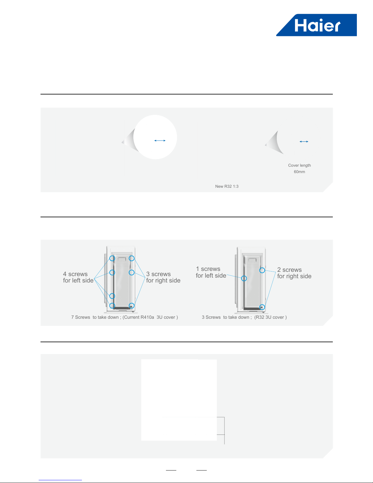
New valve cover design
Less screws to open valve cover
Easy to vacuum
Appearance
Installation
Compared with the current 1:3 valve cover , we design the new valve cover , which is more slim in the appearance;
In the installation course , installer need to take down the valve cover , then to do wiring and piping , next is the
comparison in taking down the valve cover;
General stop valve vacuum every indoor unit from one valve only , save time. ( for 1:4 outdoor unit)
Current R410a 1:3
Cover length
72.5mm
New R32 1:3
Cover length
60mm
3 screws
for right side
7 Screws to take down ; (Current R410a 3U cover )
4 screws
for left side
3 Screws to take down ; (R32 3U cover )
2 screws
for right side
1 screws
for left side
General stop valve
Page 6
4
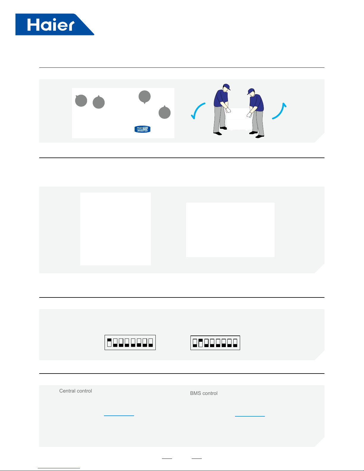
Easy to carry
Easy start up & maintenance
Left & right two handles are easy for two people carry the units;
* “88” screen show compressor frequency or failure code,
* On site testing software check all running data ;
This two tools make easy start up & maintenance ;
handle
handle
handle
handle
Cooling only /heating only
Central control/BMS control
Solution Supplier
Cooling only /heating only function for special requirement;
Central control / BMS control function meet the various needs for designer;
Note: BMS control is the function in the future
Central control
BMS control
12345678 12345678
ON
ON
SW5
SW5-1 ON cooling only
SW5-2 ON heating only
SW5
Page 7

5
Part 2 Indoor Units
1. Specification ..........................................................................................................................................................6
2. Dimension ...........................................................................................................................................................12
3. Wiring diagram ....................................................................................................................................................14
4. Air velocity and temperature distribution .............................................................................................................17
5. Installation ...........................................................................................................................................................21
Page 8
6
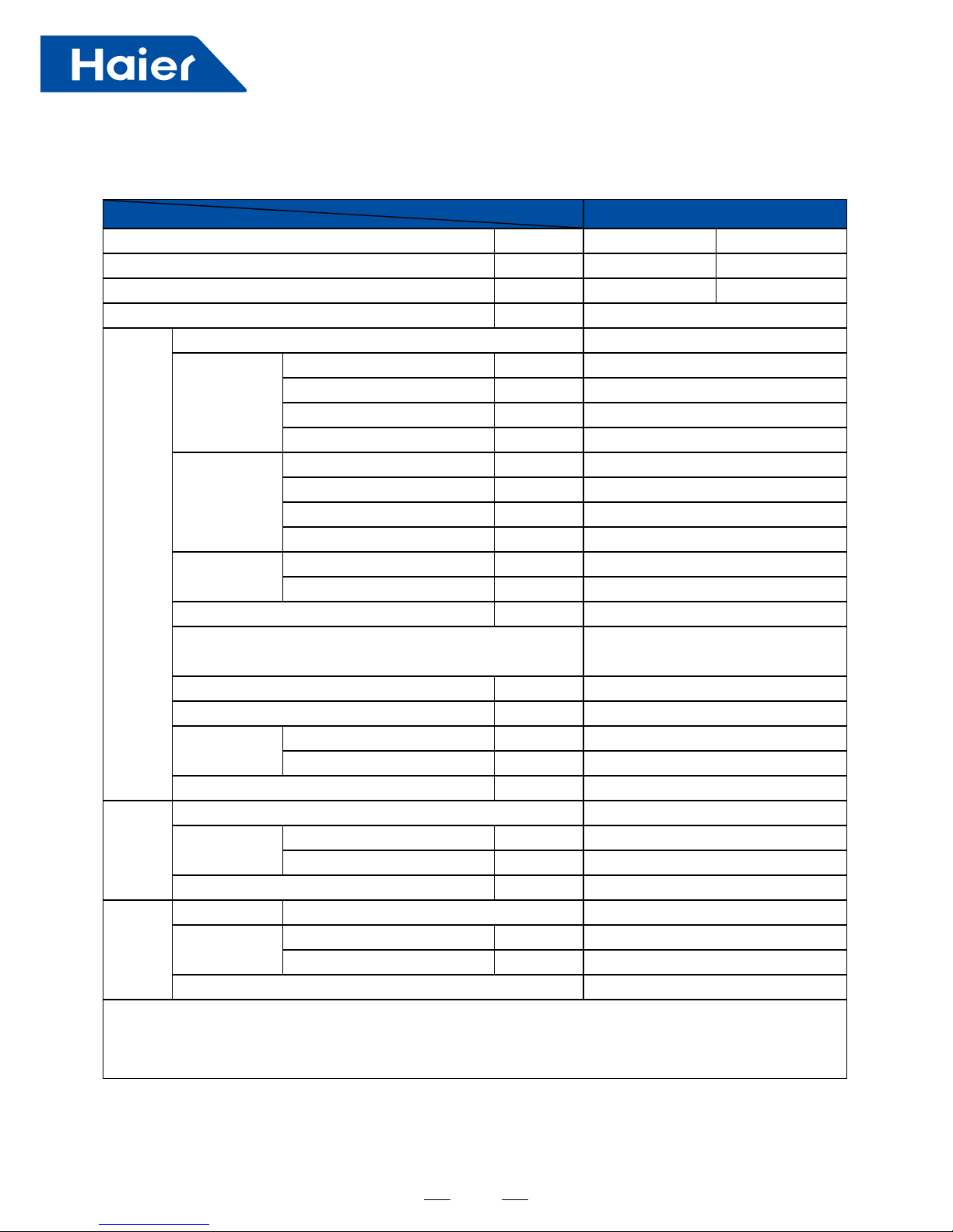
Item Model AB25S2SC1FA
Function —— Cooling Heating
capacity W 2600 3200
sensible heat ratio W 0.71 /
Dehumidifying capacity 10-³xm³/h 1.0
indoor unit
power supply 1PH, 220-240V~, 50/60Hz
Fan
Type × Number —— centrifugal*1
Speed(H-M-L) r/min 690/620/560/500
Fan motor output/input power W 10/15
Air-ows (H/M/L) m³/h 620/520/450/350
Heat exchanger
Type / Diameter mm inner grooved pipe/¢7.0
Row —— 1
Total area m² 0.272
Temp.scope
℃
2.0-7.0
Dimension
(LxWxH)
External mmxmmxmm 570*570*260
Package mmxmmxmm 718*680*380
Drainage pipe (material,I.D/O.D) mm PVC 26/32
control type(Remote/Wired) Remote YR-HBS01(O) or Wired YR-E17(O)
Fresh air hole dimension mm 95
Electricity Heater kW none
Noise level(H-
M-L)
Sound power level dB(A) 52
Sound pressure level dB(A) 36/33/30/27
weight(Net/Shipping) kg/kg 17/20
panel
panel model(color) PB-700IB(White)
Dimension
External(L*W*H) mmxmmxmm 700*700*60
Package(L*W*H) mmxmmxmm 740*750*115
Weight(Net/Shipping) kg/kg 2.8/4.8
Piping
Refrigerant Type R32
Pipe
Liquid mm Φ6.35(1/4)
Gas mm Φ9.52(3/8)
Connecting method Flared
Norminal condition: indoor temperature (cooling): 27℃DB/19℃WB, indoor temperature (heating): 20℃DB
Outdoor temperature(cooling): 35℃DB/24℃WB, outdoor temperature(heating): 7℃DB/6℃WB
The noise level will be measured in the third octave band limited values, using a Real Time Analyser calibrated sound
intensity meter.
1. Specification
Page 9
7
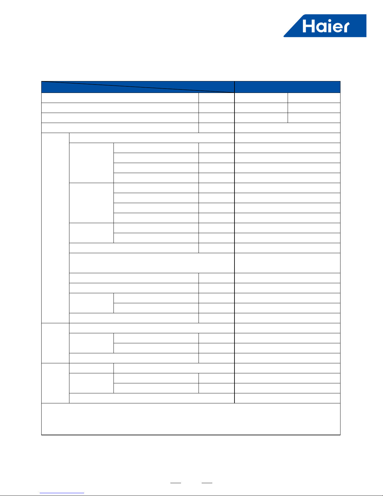
Item Model AB35S2SC1FA
Function —— Cooling Heating
capacity W 3500 4000
sensible heat ratio W 0.71 /
Dehumidifying capacity 10-³xm³/h 1.5
indoor unit
power supply 1PH, 220-240V~, 50/60Hz
Fan
Type × Number —— centrifugal*1
Speed(H-M-L) r/min 690/620/560/500
Fan motor output/input power W 10/15
Air-ows (H/M/L) m³/h 620/520/450/350
Heat exchanger
Type / Diameter mm inner grooved pipe/¢7.0
Row —— 2
Total area m² 0.544
Temp.scope
℃
2.0-7.0
Dimension
(LxWxH)
External mmxmmxmm 570*570*260
Package mmxmmxmm 718*680*380
Drainage pipe (material,I.D/O.D) mm PVC 26/32
control type(Remote/Wired) Remote YR-HBS01(O) or Wired YR-E17(O)
Fresh air hole dimension mm 95
Electricity Heater kW none
Noise level(H-
M-L)
Sound power level dB(A) 52
Sound pressure level dB(A) 36/33/30/27
weight(Net/Shipping) kg/kg 18.5/22
panel
panel model(color) PB-700IB(White)
Dimension
External(L*W*H) mmxmmxmm 700*700*60
Package(L*W*H) mmxmmxmm 740*750*115
Weight(Net/Shipping) kg/kg 2.8/4.8
Piping
Refrigerant Type R32
Pipe
Liquid mm Φ6.35(1/4)
Gas mm Φ9.52(3/8)
Connecting method Flared
Norminal condition: indoor temperature (cooling): 27℃DB/19℃WB, indoor temperature (heating): 20℃DB
Outdoor temperature(cooling): 35℃DB/24℃WB, outdoor temperature(heating): 7℃DB/6℃WB
The noise level will be measured in the third octave band limited values, using a Real Time Analyser calibrated sound
intensity meter.
Page 10
8
Item Model AD25S2SS1FA
Function —— Cooling Heating
capacity W 2500 3000
sensible heat ratio W 0.71 /
Dehumidifying capacity 10-³xm³/h 1.0
indoor unit
power supply 1PH, 220-240V~, 50/60Hz
Fan
Type × Number —— centrifugal*2
Speed(H-M-L) r/min 850/750/650/600
Fan motor output/input power W 11/15
Air-ows (H/M/L) m³/h 530/460/390/330
External static pressure pa 0/10/20/30
Heat exchanger
Type / Diameter mm inner grooved pipe/¢7.0
Row —— 2
Total area m² 0.11
Temp.scope
℃
2.0-7.0
Dimension
(LxWxH)
External mmxmmxmm 850x420x185
Package mmxmmxmm 1045x540x270
Drainage pipe (material,I.D/O.D) mm PVC 27/31
control type(Remote/Wired) Wired YR-E17(O) or Remote YR-HBS01(O)
Fresh air hole dimension mm none
Electricity Heater kW none
Noise level(H-
M-L)
Sound power level dB(A) 51
Sound pressure level dB(A) 33/30/26/23
weight(Net/Shipping) kg/kg 16/21
panel
(
optional
)
panel model(color) P1B-890IA/D
Dimension
External(L*W*H) mmxmmxmm
890/190/100
(outlet panel)/
890/290.5/32.4
(inlet panel)
Package(L*W*H) mmxmmxmm 938/335/220
Weight(Net/Shipping) kg/kg 4/5
Piping
Refrigerant Type R32
Pipe
Liquid mm Φ6.35(1/4)
Gas mm Φ9.52(3/8)
Connecting method Flared
Norminal condition: indoor temperature (cooling): 27℃DB/19℃WB, indoor temperature (heating): 20℃DB
Outdoor temperature(cooling): 35℃DB/24℃WB, outdoor temperature(heating): 7℃DB/6℃WB
The noise level will be measured in the third octave band limited values, using a Real Time Analyser calibrated sound
intensity meter.
Page 11

9
Item Model AD35S2SS1FA
Function —— Cooling Heating
capacity W 3500 4000
sensible heat ratio W 0.71 /
Dehumidifying capacity 10-³xm³/h 1.5
indoor unit
power supply 1PH, 220-240V~, 50/60Hz
Fan
Type × Number —— centrifugal*2
Speed(H-M-L) r/min 950/850/750/700
Fan motor output/input power W 16/21
Air-ows (H/M/L) m³/h 600/480/420/350
External static pressure pa 0/10/20/30
Heat exchanger
Type / Diameter mm inner grooved pipe/¢7.0
Row —— 2
Total area m² 0.11
Temp.scope
℃
2.0-7.0
Dimension
(LxWxH)
External mmxmmxmm 850x420x185
Package mmxmmxmm 1045x540x270
Drainage pipe (material,I.D/O.D) mm PVC 27/31
control type(Remote/Wired) Wired YR-E17(O) or Remote YR-HBS01(O)
Fresh air hole dimension mm none
Electricity Heater kW none
Noise level(H-
M-L)
Sound power level dB(A) 53
Sound pressure level dB(A) 35/32/29/26
weight(Net/Shipping) kg/kg 16/21
panel
(
optional
)
panel model(color) P1B-890IA/D
Dimension
External(L*W*H) mmxmmxmm
890/190/100
(outlet panel)/
890/290.5/32.4
(inlet panel)
Package(L*W*H) mmxmmxmm 938/335/220
Weight(Net/Shipping) kg/kg 4/5
Piping
Refrigerant Type R32
Pipe
Liquid mm Φ6.35(1/4)
Gas mm Φ9.52(3/8)
Connecting method Flared
Norminal condition: indoor temperature (cooling): 27℃DB/19℃WB, indoor temperature (heating): 20℃DB
Outdoor temperature(cooling): 35℃DB/24℃WB, outdoor temperature(heating): 7℃DB/6℃WB
The noise level will be measured in the third octave band limited values, using a Real Time Analyser calibrated sound
intensity meter.
Page 12
10
Item Model AD50S2SM1FA
Function —— Cooling Heating
capacity W 5000 6000
sensible heat ratio W 0.73 /
Dehumidifying capacity 10-³xm³/h 1.8
indoor unit
power supply 1PH, 220-240V~, 50/60Hz
Fan
Type × Number —— centrifugal*2
Speed(H-M-L) r/min 900/820/770/720
Fan motor output/input power W 45/70
Air-ows (H/M/L) m³/h 1080/900/780/660
External static pressure Pa 150/130/120/110/100/90/70/50/37/25
Heat exchanger
Type / Diameter mm inner grooved pipe/¢7.0
Row —— 2
Total area m² /
Temp.scope
℃
2.0-7.0
Dimension
(LxWxH)
External mmxmmxmm 957/655/250
Package mmxmmxmm 1170/860/340
Drainage pipe (material,I.D/O.D) mm PVC 25/29
control type(Remote/Wired) Wired YR-E17(O) or Remote YR-HBS01(O)
Fresh air hole dimension mm 145
Electricity Heater kW none
Noise level(H-
M-L)
Sound power level dB(A) 57
Sound pressure level dB(A) 37/34/32/29
weight(Net/Shipping) kg/kg 26/33
Piping
Refrigerant Type R32
Pipe
Liquid mm Φ6.35(1/4)
Gas mm Φ12.7(1/2)
Connecting method Flared
Norminal condition: indoor temperature (cooling): 27℃DB/19℃WB, indoor temperature (heating): 20℃DB
Outdoor temperature(cooling): 35℃DB/24℃WB, outdoor temperature(heating): 7℃DB/6℃WB
The noise level will be measured in the third octave band limited values, using a Real Time Analyser calibrated sound
intensity meter.
Page 13
11
Item Model AD71S2SM1FA
Function cooling heating
Capacity KW 7.1(2.0~8.2) 8.0(2.5~8.5)
Sensible heat ratio 0.74 /
Total power input KW 2.15(0.6~2.6) 2.16(0.6~2.6)
Max. power input W
3000 3000
EER or COP W/W 3.30 3.71
Dehumidifying capacity 10
-
³×m³/h 2.5
Power cable H05RN-F 4G 6.0mm2
Power source N, V, Hz
1PH, 220-240V~, 50/60Hz
Running /Max.Running current A / A 9.7(2.3-12)/16 9.8(2.3-12)/16
Start Current A 3
Indoor unit
Unit model (color) AD71S2SM1FA
Fan
Type × Number CENTRIFUGALX2
Speed(H-M-L) r/min 1130/950/820/780
Fan motor output/ input power W 85/111
Air-ow(H-M-L) m³/h 1440/1140/900/800
External static pressure Pa 25/37//50/70/90/100/110/120/130/150
Heat
exchanger
Type / Diameter mm inner grooved pipe/φ7.0
Row 3
Total Area m² 7.668
Dimension
External(L×W×H) mm×mm×mm 957/655/250
Package(L×W×H) mm×mm×mm 1170/860/340
Drainage pipe (material , I.D./O.D.) mm PVC 25/29
Controller
(O-Optional,S-Standard)
Wired YR-E16(O)/YR-E17(S)
Fresh air hole dimension mm NONE
Electricity Heater kW NONE
Sound power Noise level (H-M-L) dB(A) 58
Sound pressure Noise level (H-M-L) dB(A) 42/38/35
Pipe
Liquid Pipe(mm) 9.52
Gas Pipe(mm) 15.88
Connecting Method ared
Weight (Net / Shipping) kg / kg 31.2/36.8
Norminal condition: indoor temperature (cooling): 27℃DB/19℃WB, indoor temperature (heating): 20℃DB
Outdoor temperature(cooling): 35℃DB/24℃WB, outdoor temperature(heating): 7℃DB/6℃WB
The noise level will be measured in the third octave band limited values, using a Real Time Analyser calibrated sound intensity
meter. It is a sound pressure noise level.
Page 14
12
AB25S2SC1FA AB35S2SC1FA
AD25S2SC1FA AD35S2SC1FA
420
370
892
850
185
640
90
760
152
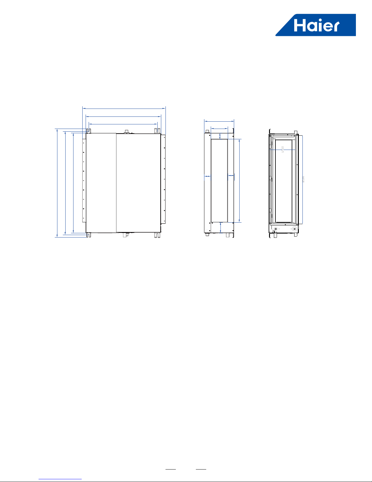
2. Dimension
957
990
1050
595.5
655
720
250
148
57
57
57
103
797
Note: The cushion pasted in the bottom plate isn't included in the thickness data.
unit : mm
Page 15
13
957
990
1050
595.5
655
720
250
148
57
57
57
103
797
Note: The cushion pasted in the bottom plate isn't included in the thickness data.
AD50S2SM1FA AD71S2SM1FA
Page 16
14
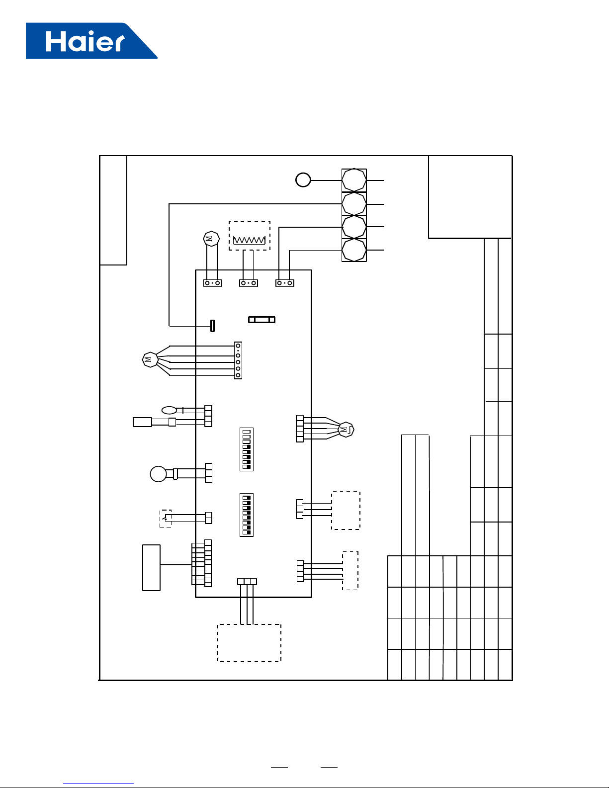
3. Wiring diagram
AB25S2SC1FA AB35S2SC1FA
TO OUT DOOR
0150523323
BM1-1
BM1-7
BM1-8
TYPE DEFINE
OFFOFF
BM1-2 BM1-3
BTU
B:BLACK
R:RED
W:WHITE
Y/G:YELLOW/GREEN
TEMP.
SENSOR
ROOM
SENSOR
FLOAT
SWITCH
HEATER
PUMP
UP/DOWN
CN9
CN1
CN6
PANNEL
CN4
CN11
CN19
CN13
CN3
ON
CN7
CN21
T5A/250VAC
FUSE
BM3
2
1
3
B
W
R
Y/G
OFF OFF OFF
ON OFF OFF
OFF ON OFF
ON ON OFF
OFF OFF ON
ON OFF ON
OFF ON ON
ON ON ON
9000
12000
18000
24000
28000
36000
48000
60000
NOTE1.DASHED PART ARE OPTIONAL.
2. USER SHOULD NOT TO SET BM1 AND BM3
CH1
OFF OFF
BM1-4
BM1-5
BM1-6
OFF
OFF
CN16
G
CN8
G
TEMP.
PIPING
DC FAN
ROOMCARD
U-HOME
WIRED
CONTROLLER
B
A
C
BA
C
REMOTE
CENTRAL
87654321
ON
BM1
OFF
87654321
N
OFF
Room card
available
unavailable
ON
AB25S2SC1FA
AB35S2SC1FA
Default
Page 17
15
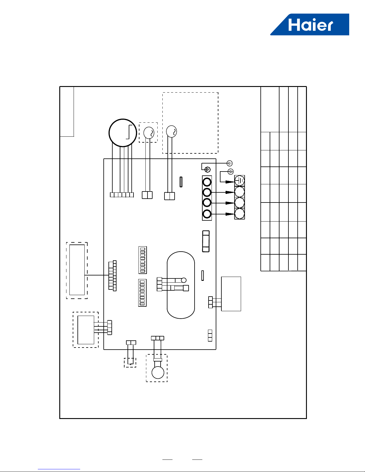
AD25S2SC1FA AD35S2SC1FA
Y/G:YELLOW/GREEN
NOTE:
1.DASHED PARTS ARE OPTIONAL.
2.
USER SHOULD NOT SET SW01 AND
SW03 WITHOUT GUIDENCE.
3.WHEN ONE WIRED CONTROLLER CONTROL MULTIPLE INDOOR UNIT,
IT CAN CONNECT ANOTHER INDOOR UNIT BY CN22 OR CN22-1.
WHEN TWO WIRD CONTROLLERS CONTROL ONE INDOOR UNIT,
THE WIRED CONTROLLER NEED CONNECT WITH CN22 AND CN22-1.
TEMP.
SENSOR
ROOM
SENSOR
PIPING
TEMP.
ROOMCARD
R O T O M N A F C D
SW03
FUSE
WIRED
CONTROLLER
FLOAT
SWITCH
WIFI
MODULE
PUMP
TO OUT DOOR
2
1
3
Y/G
M
12345678
ON
INFRARED
REMOTE RECEIVER
M
B
A
C
B
A
C
OFF
0150523322
2
1
3
N L S
B A
C
SW01
12345678
ON
OFF
FRESH AIR MOTOR
(SW01-6 select OFF) /
EXTERNAL ALARM OUTPUT
(SW01-6 select ON)
( Contact rating_230VAC,3A)
M
CN21
Heater_L
CH4
Heater_N
CH2
CN5
CN4
CN34
CN16
CH1
SW01-1
SW01-2
SW01-3
OFF
SW01-4
SW01-5
SW01-6
SW01-7
SW01-8
MODEL
OFF
AD35S2SS1FA
OFF
OFF
OFF
ON
ON
OFF
CN13
CN6
CN41
CN22
CN22-1
4.SW03-5
->SW03-08 ARE USED FOR
ADDRESS SETTING ON THE
SITUATION OF ONE WIRED CONTROLLER CONTROL MORE THAN
ONE INDOOR UNIT.
5.REFER TO SERVICE MANUL TO GET MUCH MORE DETAILS
ABOUT THE STATIC PRESSURE LEVEL SELECTION.
CN1
AD25S2SS1FA
ON
OFF
OFF
OFF
OFF
OFF
OFF
OFF
SW03-1 SW03-2 SW03-3 SW03-4 SW03-5 SW03-6 SW03-7 SW03-8
OFF OFF OFF OFF OFF OFF OFF OFF
FOR ALL
DUCT MODEL
Page 18
16
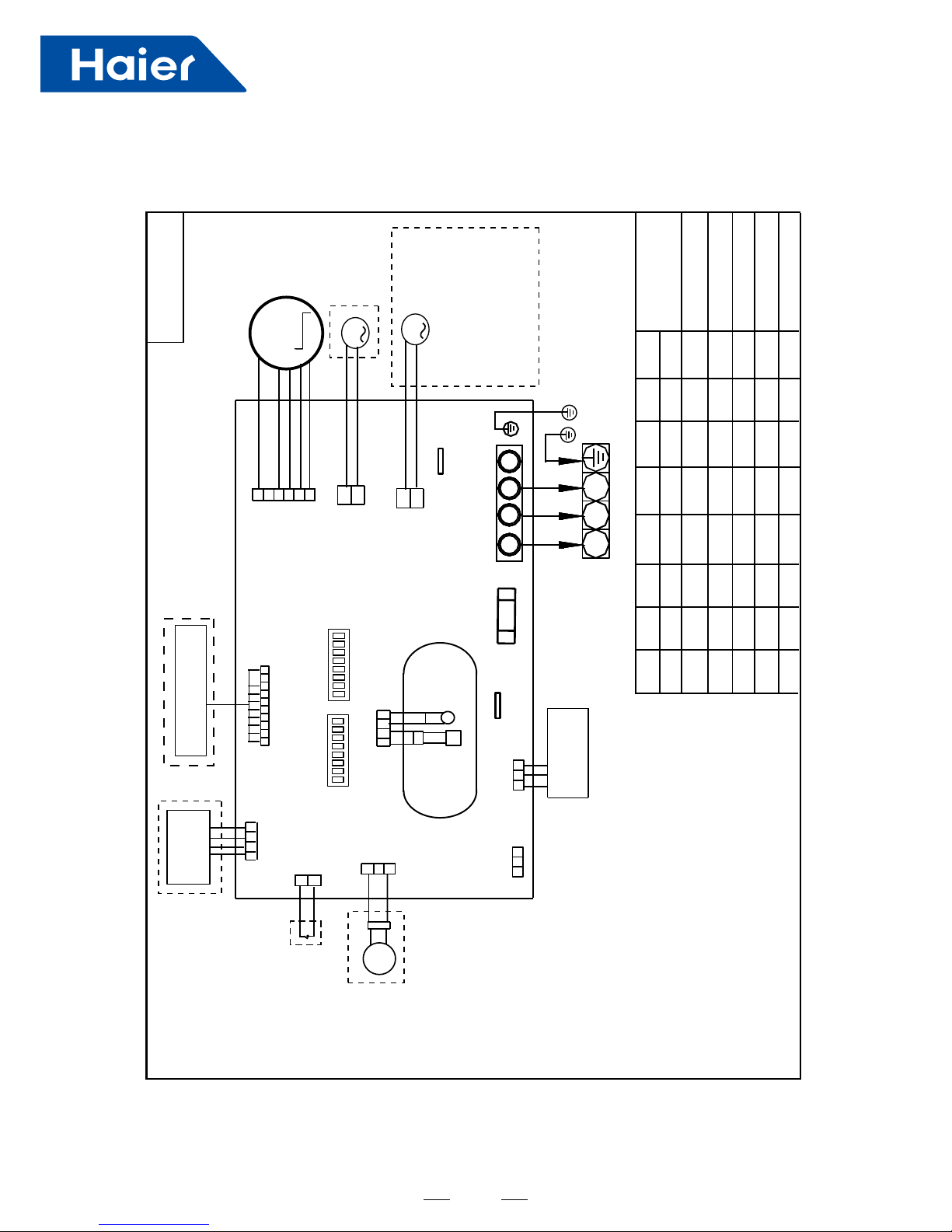
AD50S2SM1FA AD71S2SM1FA
Y/G:YELLOW/GREEN
NOTE:
1.DASHED PARTS ARE OPTIONAL.
2.SW03-4 IS AT ON POSITION,DO NOT CHANGE
THE SETTINGS OF SWITCHS WITHOUT GUIDANCE.
3.WHEN ONE WIRED CONTROLLER CONTROL MULTIPLE INDOOR UNIT,
IT CAN CONNECT ANOTHER INDOOR UNIT BY CN22 OR CN22-1.
WHEN TWO WIRD CONTROLLERS CONTROL ONE INDOOR UNIT,
THE WIRED CONTROLLER NEED CONNECT WITH CN22 AND CN22-1.
TEMP.
SENSOR
ROOM
SENSOR
PIPING
TEMP.
ROOMCARD
R O T O M N A F C D
SW03
FUSE
WIRED
CONTROLLER
FLOAT
SWITCH
WIFI
MODULE
PUMP
TO OUT DOOR
2
1
3
Y/G
M
12345678
ON
REMOTE RECEIVER
M
B
A
C
B
A
C
OFF
0150523302
2
1
3
N L S
B A
C
SW01
12345678
ON
OFF
FRESH AIR MOTOR
(SW01-6 select OFF) /
EXTERNAL ALARM OUTPUT
(SW01-6 select ON)
( Contact rating_230VAC,3A)
M
CN21
Heater_L
CH4
Heater_N
CH2
CN5
CN4
CN34
CN16
CH1
SW01-1
SW01-2
SW01-3
ON
SW01-4
SW01-5
SW01-6
SW01-7
SW01-8
MODEL
OFF
AM24LP2VHA
OFF
OFF
OFF
OFF
OFF
OFF
OFF
ON
OFF
ON
ON
ADH071M3ERG
OFF
OFF
ON
CN13
CN6
CN41
CN22
CN22-1
4.SW03-5
->SW03-08 IS USED FOR
ADDRESS SETTING ON THE
SITUATION OF ONE WIRED CONTROLLER CONTROL MORE THAN
ONE INDOOR UNIT.
5.REFER TO SERVICE MANUL TO GET MUCH MORE DETAILS
ABOUT THE STATIC PRESSURE LEVEL SELECTION.
CN1
AD71S2SM1FA
OFF
OFF
OFF
OFF
OFF
OFF
ON
ON
ON
OFF
OFF
OFF
OFF
OFF OFF
ON
AD50S2SM1FA
SW03-1
SW03-2
SW03-3
FOR ALL DUCTED
MODEL
SW03-4 SW03-5 SW03-6
SW03-7
SW03-8
OFF OFF OFF OFF OFF OFF OFF ON
Page 19
17
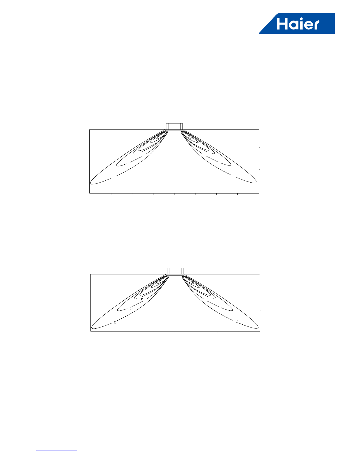
4. Air velocity and temperature distribution
a. Cooling / Air Velocity Distribution
Cooling
Blowy angle:40
Air Velocity Distribution
1.5m/s
1.5m/s
1.0m/s
1.0m/s
0.5m/s
2.7m
2m
2m2m
1m
1m
1m
4m
3m
3m
4m
0m
0m
0.5m/s
b. Cooling / Temperature Distribution
Cooling
Blowy angle:40
Temperature Distribution
27
52
22
22
27
25
2.7m
2m
1m
0m
4m
3m
2m
1m
0m
1m
2m 3m
4m
AB25S2SC1FA AB35S2SC1FA
Page 20
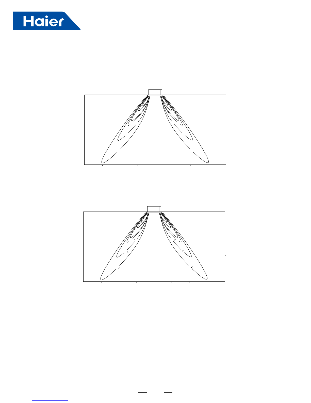
18
2.7m
2m
1m
0m
1.5m/s
1.5m/s
1.0m/s
1.0m/s
0.5m/s
2m2m
1m
1m
4m
3m
3m
4m
0m
0.5m/s
c. Heating / Air Velocity Distribution
Heating
Blowy angle:70
Air velocity Distribution
d. Heating / Temperature Distribution
Heating
Blowy angle:70
Temperature Distribution
22
27
25
22
25
27
4m
3m
2m2m
1m
1m
3m
4m
0m
2.7m
2m
1m
0m
Page 21
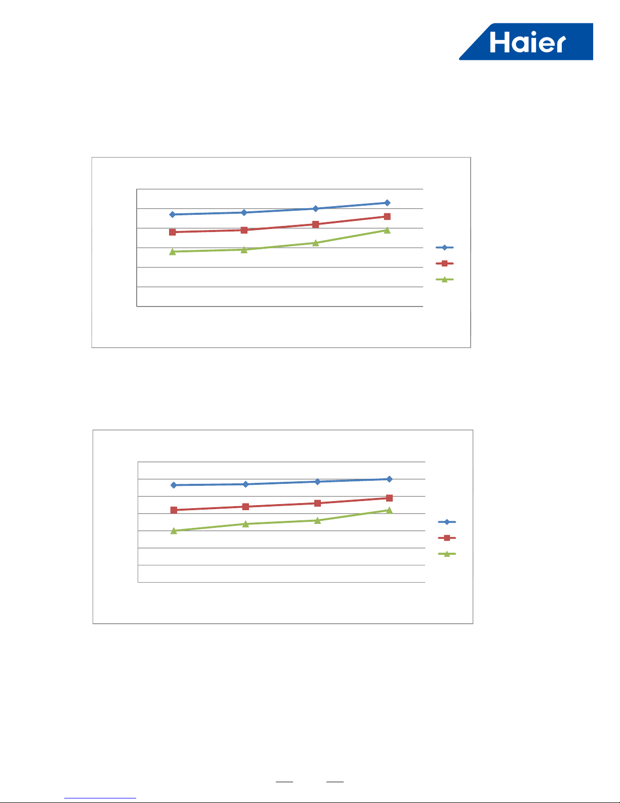
19
300
400
500
600
ow m3/h
AIR FLOW AND STATIC PRESSURE CHART
H
0
100
200
300
400
30 Pa 20 Pa 10 Pa 0 Pa
air flow m 3
static pressure (Pa)
H
M
L
500
600
700
h
AIR FLOW AND STATIC PRESSURE CHART
30 Pa 20 Pa 10 Pa 0 Pa
static pressure (Pa)
100
200
300
400
500
600
air flow m3/h
H
M
L
0
100
30 Pa 20 Pa 10 Pa 0 Pa
static pressure (Pa)
L
AD25S2SS1FA
AD35S2SS1FA
Temperature distribution
Page 22
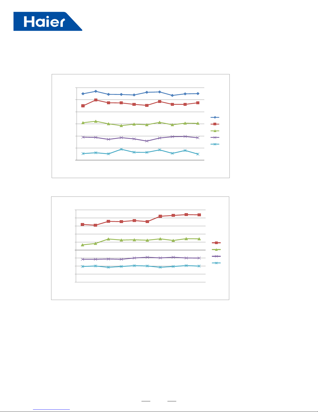
20
600
700
800
900
1000
1100
1200
150Pa 130Pa 120Pa 110Pa 100Pa 90Pa 70Pa 50Pa 37Pa 25Pa
air flow m3/h
static pressure (Pa)
AIR FLOW AND STATIC PRESSURE CHART
S-H
H
M
L
S
AD50S2SM1FA
AD71S2SM1FA
600
700
800
900
1000
1100
1200
1300
1400
1500
150Pa 130Pa 120Pa 110Pa 100Pa 90Pa 70Pa 50Pa 37Pa 25Pa
air flow m3/h
static pressure (Pa)
AIRFLOW AND STATIC PRESSURE CHART
H
M
L
S
Page 23
21
5. Installation
For AB25S2SC1FA/AB35S2SC1FA
1. Installation procedure
Page 24
22
AB25S2SC1FA
AB35S2SC1FA
AB25S2SC1FA
AB35S2SC1FA
Page 25

23
Page 26
24
Page 27
25
AB25S2SC1FA
AB35S2SC1FA
Page 28
26
Page 29
27
For AD25S2SC1FA/AD35S2SC1FA
Installation procedure
AD25S2SS1FA
AD35S2SS1FA
Page 30
28
AD25S2SS1FA AD35S2SS1FA
AD25S2SS1FA AD35S2SS1FA
Page 31

29
Page 32

30
AD25S2SS1FA AD35S2SS1FA
Page 33

31
Page 34

32
The specification of power cable is HO5RN-F3G 4.0mm .
The specification of cable between indoor unit to outdoor unit is HO5RN-F4G 2.5mm
2
2
Page 35

33
For AD50S2SM1FA/AD71S2SM1FA
Installation procedure
1. Applicable ambient temperature range:
The machine is adaptive in following situation
Cooling
Heating
Indoor temperature
Outdoor temperature
Indoor temperature
Outdoor temperature
max. DB/WB
min. DB/WB
max. DB/WB
min. DB/WB
max. DB/WB
min. DB/WB
max. DB/WB
min. DB/WB
32/23 C
18/14 C
46/26 C
10/6 C
27 C
15 C
24/18 C
-15 C
2. If the supply cord is damaged, it must be replaced by the manufacturer or its service agent or a similar qualified person.
3. If the fuse on the indoor PC board is broken please change it with the type of T 6.3A /250VAC(For series 24,28,36,48).
4. The wiring method should be in line with the local wiring standard.
5. The power cable should be:
H05RN-F 3G 4.0mm
2
;
The connecting cable should be:
H05RN-F 4G 2.0mm
2
All the cables shall have got the European authentication certificate. During installation, when the connecting cables
break off, it must be assured that the grouding wire is the last one to be broken off.
6. The power cable and conne
ct cable should be self-provided.
7. The breaker of the air conditioner should be all-pole switch, and the distance between its two contacts should be no
less than 3mm.
8. The indoor unit installation height is at least 2.5m.
9. A leakage breaker must be installed.
10.
For AD50S2SM1FA AD71S2SM1FA
,we can get the 10 different ESP through adjust wired controllerYR-E17,please refer
below:
AD50S2SM1FA AD71S2SM1FA
Stacc pressure
grade
1 2 3
5
4
7
6
8 9 10
Stacc pressure 25Pa 37Pa 50Pa 70Pa 90Pa 100Pa 110Pa 120Pa 130Pa 150Pa
Adjsutment metchod bywired controller YR-E17:In the state of ON and non screen saving state, press Fan+ Set keys for
5s to enter stac pressure grade adjustmentstate with stac pressure icon flashing and current stacpressure grade
stacally displaying. Press key↑↓ to changestac pressure grade, then press Set key to confirm.
Details please refer to wired controller operaon & installaon manual.
Adjsutment metchod by Infrared remote controller+Infrared receiver RE-02:Step a:set the Infrared remote controller at
condion: FAN mode ,fan speed high Step b:then aim the remote contr
oller at the infrared remote receiver RE-02,
press HEALTH buon 4+N mes(1≤N≤10,integer)within 12 seconds ,then the receiver will beep N+1 mes ,the
stac pressure level N is been set successfully.
Note:For Infrared remote controller YR-HBS01, need press ON/OFF buon make the controller’s at OFF status first,then
open the buon cover press FRESH buon will enter FAN mode interface.
Page 36

34
Avoid installation and use at those places listed below.
Places exposed to oil splashes or steam (e.g. kitchens and machine plants).
Installation and use at such places incur deteriorations in the performance or corrosion with the heat exchanger or damage
in molded synthetic resin parts.
Places where corrosive gas (such as sulfurous acid gas) or inflammable gas (thinner, gasoline etc.) in generated or
remains. Installation and use at such places cause corrosion in the heat exchanger and damage in molded synthet
ic
resin parts.
Places adjacent to equipment generating electromagnetic waves or high-frequency waves such as in hospitals.
Generated noise may cause malfunctioning of the controller.
NOTE
All wiring of this installation must comply with NATIONAL, STATE AND LOCAL REGULATIONS. These instructions
do not cover all variations for every kind of installation circumstance. Should further information be desired or should particular
problems occur, the matter should be referred to your local distr
ibutor.
WARNING
BE SURE TO READ THESE INSTRUCTIONS CAREFULLY BEFORE BEGINNING INSTALLATION. FAILURE TO FOLLOW
THESE INSTRUCTIONS COULD CAUSE SERIOUS INJURY OR DEATH, EQUIPMENT MALFUNCTION AND/OR
PROPERTY DAMAGE.
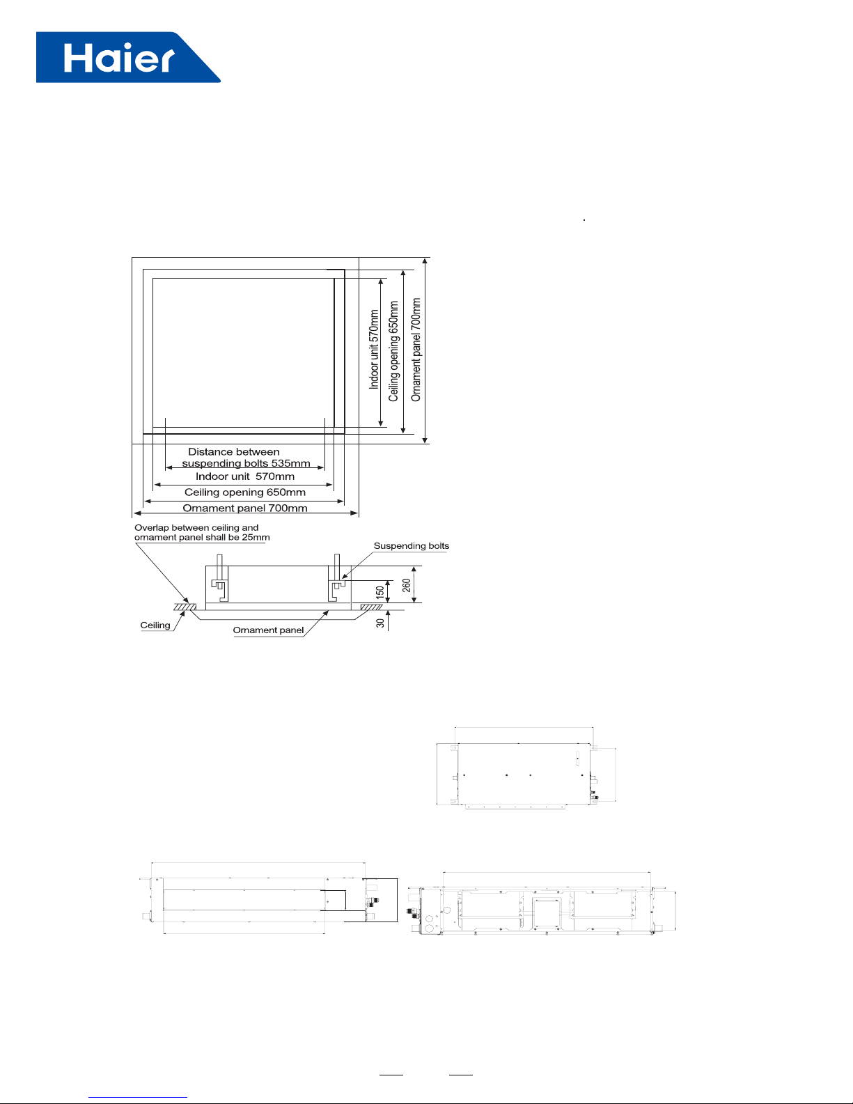
Preparation of indoor unit
Before or during the installation of the unit, assemble necessary optional panel etc. depending on the specific type.
Select places for installation satisfying following conditions and at the same time obtain the consent on the part
of your client user.
Places where chi
lled or heated air circulates freely. When the installation height exceeds 3m warmed air stays close to
the ceiling. In such cases, suggest your client users to install air circulators.
Places where perfect drainage can be prepared and sufficient drainage.
Places free from air disturbances to the suction port and blowout hole of the indoor unit, places where the fire alarm
may not malfunction or short-circuit.
Places with the environmental dew-point temperature is lower than 28 and the relative humidity is less than 80 %.
(When installin
g at a place under a high humidity environment, pay sufficient attention to the prevention of dewing such
as thermal insulation of the unit. )
Ceiling height shall have the following height.
50mm
Obstacle
Installation space
C
Combination
with silent
panel
366mm
a.
b.
c.
d.
e.
a.
b.
c.
100mm 100mm
Pipe size
AD50S2SM1FA AD71S2SM1FA
AD50S2SM1FA
AD71S2SM1FA
Model Liquid side Gas side
9.52mm 15.88mm
6.35mm 12.7mm
Page 37

35
AD50S2SM1FA AD71S2SM1FA
Dimensions
A(mm)
B(mm) C(mm)
Model
D(mm) E(mm) F(mm)
983 1433 1493 595 740 800
AD50S2SM1FA AD71S2SM1FA
Page 38

36
21mmAD50S2SM1FA AD71S2SM1FA
Unit model The size of drain opening
Page 39

37
Page 40

38
Selection of size of power supply and interconnecting wires
Select wire sizes and circuit protection from table below. (This table shows 20 m length wires with less than 2% voltage drop.)
Item
Model
Phase
Switch
breaker
(A)
Circuit breaker
Overcurrent
protector
rated capacity
(A)
Power source
wire size
(minimum)
(mm
2
)
Switch
breaker(A)
Earth leakage breaker
Leak
current(mA)
301 40 26 4.0 40AD50S2SM1FA AD71S2SM1FA
The specification of power cable is HO5RN-F3G 4.0mm .
The specification of cable between indoor unit to outdoor unit is HO5RN-F4G 2.5mm
2
2
POWER SUPPLY & INDOOR-OUTDOOR CONNECTION:
Make wiring to supply power to the outdoor unit, so that the power for the indoor unit is supplied by outdoor
unit terminal blocks.
WIRED CONTROLLER& INDOOR PCB CONNECTION(one for one wiring type):
.
Note:When do the wired controller & indoor PCB wiring work for model AD50/71S2SM1FA,do not connect
the shielded wired to the unit’s shell,do not parallel wiring with strong electric lines within 0.3 meters, please
keep strong lines and the signal lines separately.
INDOOR UNIT PCB
CN22
WIRED
CONTROLLER
CON1
A
B
C
A
B
C
Page 41

39
- The installation of pipe-work shall be kept to a minimum.
- Pipe-work shall be protected from physical damage and shall not be installed in an unventilated space, if that space is
smaller than Amin(2m2).
- Compliance with national gas regulations shall be observed.
- Mechanical connections shall be accessible for maintenance purposes.
- The minimum floor area of the room: 2 m2.
- The maximum refrigerant charge amount: 1.7 kg.
- Information for handling, installation, cleaning, servicing and disposal of refrigerant.
- Warning: Keep any required ventilation openings clear of obstruction.
- Notice: Servicing shall be performed only as recommended by the manufacturer.
Unventilated areas
- Warning: The appliance shall be stored in a well-ventilated area where the room size corresponds to the room area as
specified.
- Warning: The appliance shall be stored in a room without continuously operating open flames (e.g. an operating gas
appliance) and ignition sources (e.g. an operating electric heater).
Qualification of workers
- Specific information about the required qualification of the working personnel for maintenance, service and repair
operations.
- Warning: Every working procedure that affects safety means shall only be carried out by competent persons.
Examples for such working procedures are:
- breaking into the refrigerating circuit.
- opening of sealed components
- opening of ventilated enclosures.
Information on servicing
- Prior to beginning work on systems, safety checks are necessary to ensure that the risk of ignition is minimized.
- Work shall be undertaken under a controlled procedure so as to minimized the risk of flammable gas or vapor being
present while the work is being performed.
- Work in confined spaces shall be avoided. The area around the workspace shall be sectioned off. Ensure that the conditions
within the area have been made safe by control of flammable material.
Checking for presence of refrigerant
- The area shall be checked with an appropriate refrigerant detector prior to and during work. The leak detection equipment
should be suitable for use with all applicable refrigerants, i.e. non-sparking, adequately sealed or intrinsically safe.
Presence of fire extinguisher
- If any hot work is to be conducted, appropriate fire extinguishing equipment shall be available to hand. Have a dry powder
or CO2 fire extinguisher adjacent to the charging area.
No ignition sources
- All possible ignition sources, including cigarette smoking, should be kept sufficiently far away from the site of installation,
repairing, removing and disposal. Prior to work taking place, the area around the equipment is to be surveyed to make sure
that there are no flammable hazards or ignition risks. “No Smoking” signs shall be displayed.
Ventilated area
- Ensure that the area is in the open or that it is adequately ventilated before breaking into the system or conducting any hot
work. A degree of ventilation shall continue during the period that the work is carried out. The ventilation should safely disperse
any released refrigerant and preferably expel it externally into the atmosphere.
Checks to the refrigeration equipment
- Where electrical components are being changed, they shall be fit for the purpose and to the correct specification. At all
times the manufacturer’s maintenance and service guidelines shall be followed. If in doubt, consult the manufacturer’s
technical department for assistance.
The following checks shall be applied to installations
- The charge size is in accordance with the room size within which the refrigerant containing parts are installed;
- The ventilation machinery and outlets are operating adequately and are not obstructed;
- If an indirect refrigerating circuit is being used, the secondary circuit shall be checked for the presence of refrigerant;
- Marking to the equipment continues to be visible and legible. Markings and signs that are illegible shall be corrected;
- Refrigeration pipe or components are installed in a position where they are unlikely to be exposed to any substance which
may corrode refrigerant containing components, unless the components are constructed of materials which are inherently
resistant to being corroded or are suitably protected against being so corroded.
Cautions
Page 42

40
Checks to electrical devices
- Repair and maintenance to electrical components shall include initial safety checks and component inspection
procedures. If a fault exists that could compromise safety, then no electrical supply shall be connected to the circuit until it
is satisfactorily dealt with. If the fault cannot be corrected immediately but it is necessary to continue operation, an
adequate temporary solution shall be used. This shall be reported to the owner of the equipment so all parties are
advised.
- Initial safety checks shall include:
• that capacitors are discharged: this shall be done in a safe manner to avoid possibility of sparking;
• that no live electrical components and wiring are exposed while charging, recovering or purging the system;
• that there is continuity of earth bonding.
Repairs to sealed components
- During repairs to sealed components, all electrical supplies shall be disconnected prior to any removal of sealed
covers, etc. If it is absolutely necessary to have an electrical supply to equipment during servicing, then a permanently
operating form of leak detection shall be located at the most critical point to warn of a potentially hazardous situation.
- Ensure that by working on electrical components, the casing is not altered in such a way that the level of protection is
affected, including damage to cables, excessive number of connections, terminals not made to original specification,
damage to seals, incorrect fitting of glands, etc.
- Ensure that the apparatus is mounted securely.
- Ensure that seals or sealing materials have not degraded to the point that they no longer serve the purpose of
preventing the ingress of flammable atmospheres. Replacement parts shall be in accordance with the manufacturer’s
specifications.
Repair to intrinsically safe components
- Do not apply any permanent inductive or capacitance loads to the circuit without ensuring that this will not exceed the
permissible voltage and current permitted for the equipment in use.
- Intrinsically safe components are the only types that can be worked on while live in the presence of a flammable
atmosphere.
- Replace components only with parts specified by the manufacturer. Other parts may result in the ignition of refrigerant
in the atmosphere from a leak.
Cabling
- Check that cabling will not be subject to wear, corrosion, excessive pressure, vibration, sharp edges or any other
adverse environmental effects. The check shall also take into account the effects of aging or continual vibration from
sources such as compressors or fans.
Detection of flammable refrigerants
Removal and evacuation
- The refrigerant charge shall be recovered into the correct recovery cylinders and the system shall be “flushed” with
OFN to render the unit safe. This process may need to be repeated several times.
- Compressed air or oxygen shall not be used for purging refrigerant systems.
- Flushing shall be achieved by breaking the vacuum in the system with OFN and continuing to fill until the working
pressure is achieved, then venting to atmosphere, and finally pulling down to a vacuum. This process shall be repeated
until no refrigerant is within the system. When the final OFN charge is used, the system shall be vented down to
atmospheric pressure to enable work to take place.
- The vacuum pump is not close to any ignition sources and that ventilation is available.
Charging procedures
- Ensure that contamination of different refrigerants does not occur when using charging equipment. Hoses or lines
shall be as short as possible to minimise the amount of refrigerant contained in them.
- Cylinders shall be kept upright.
- Ensure that the refrigeration system is earthed prior to charging the system with refrigerant.
- Label the system when charging is complete (if not already).
- Extreme care shall be taken not to overfill the refrigeration system.
- Prior to recharging the system, it shall be pressure-tested with the appropriate purging gas. The system shall be leaktested on completion of charging but prior to commissioning. A follow up leak test shall be carried out prior to leaving the
site.
Decommissioning
- Before carrying out this procedure, it is essential that the technician is completely familiar with the equipment and all
its detail.
- Prior to the task being carried out, an oil and refrigerant sample shall be taken in case analysis is required prior to reuse of reclaimed refrigerant.
- Electrical power must be available before the task is commenced.
Page 43

41
- Become familiar with the equipment and its operation.
- Isolate system electrically.
- Before attempting the procedure, ensure that:
• mechanical handling equipment is available, if required, for handling refrigerant cylinders;
• all personal protective equipment is available and being used correctly;
• the recovery process is supervised at all times by a competent person;
• recovery equipment and cylinders conform to the appropriate standards.
- Pump down refrigerant system, if possible.
- If a vacuum is not possible, make a manifold so that refrigerant can be removed from various parts of the system.
- Make sure that cylinder is situated on the scales before recovery takes place.
- Start the recovery machine and operate in accordance with manufacturer's instructions.
- Do not overfill cylinders. (No more than 80 % volume liquid charge).
- Do not exceed the maximum working pressure of the cylinder, even temporarily.
- When the cylinders have been filled correctly and the process completed, make sure that the cylinders and the
equipment are removed from site promptly and all isolation valves on the equipment are closed off.
- Recovered refrigerant shall not be charged into another refrigeration system unless it has been cleaned and checked.
Labelling
- Equipment shall be labelled stating that it has been de-commissioned and emptied of refrigerant. The label shall be
dated and signed.
- Ensure that there are labels on the equipment stating the equipment contains flammable refrigerant.
Recovery
- When transferring refrigerant into cylinders, ensure that only appropriate refrigerant recovery cylinders are employed.
- Ensure that the correct number of cylinders for holding the total system charge are available. All cylinders to be used
are designated for the recovered refrigerant and labelled for that refrigerant (i.e. special cylinders for the recovery of
refrigerant).
- Cylinders shall be complete with pressure-relief valve and associated shut-off valves in good working order. Empty
recovery cylinders are evacuated and, if possible, cooled before recovery occurs.
- The recovery equipment shall be in good working order with a set of instructions concerning the equipment that is at
hand and shall be suitable for the recovery of all appropriate refrigerants.
- A set of calibrated weighing scales shall be available and in good working order. Hoses shall be complete with leakfree disconnect couplings and in good condition. Before using the recovery machine, check that it is in satisfactory
working order, has been properly maintained and that any associated electrical components are sealed to prevent ignition
in the event of a refrigerant release.
- The recovered refrigerant shall be returned to the refrigerant supplier in the correct recovery cylinder, and the relevant
waste transfer note arranged.
- Do not mix refrigerants in recovery units and especially not in cylinders.
- If compressors or compressor oils are to be removed, ensure that they have been evacuated to an acceptable level to
make certain that flammable refrigerant does not remain within the lubricant.
- The evacuation process shall be carried out prior to returning the compressor to the suppliers.
- Only electric heating to the compressor body shall be employed to accelerate this process.
Page 44

42
1. Specification ......................................................................................................................................................43
2. Dimension ..........................................................................................................................................................52
3. Wiring diagram ..................................................................................................................................................55
4. Wiring connection .............................................................................................................................................58
5. Refrigerant diagram ..........................................................................................................................................60
6. Limitation values on pipe installation .............................................................................................................63
7. Combination and the data ................................................................................................................................65
8. Sound pressure level ........................................................................................................................................79
9. Outdoor performance curves ...........................................................................................................................83
10. Installation .......................................................................................................................................................88
Part 3 Outdoor Units
Page 45

43
1. Specification
Item Model 1U71S2SG1FA
Power cable H05RN-F 4G 6.0mm2
Communication cable/Connecting cable H05RN-F 4G 2.5mm2
Power source N, V, Hz 1PH,220-230VAC,50/60HZ
Start Current A 3 3
Outdoor
unit
Unit model (color) 1U71S2SG1FA(WHITE)
Compressor
Model / Manufacture SNB130FGYM2/SNB130FGYMC-L1(MGC
)
Oil model FV50S
Oil type PVE
Oil charging 500CC
Type Rotary
Fan
Type × Number axial×1
Speed r/min 950/830/750/700/500/420/300
Fan motor output/input
power pow
W 97/70
Air-ow(H-M-L) m³/h 3000
Heat
exchanger
Type / Diameter mm TP2M/Φ7.9
Row / Fin pitch 2/1.65
Dimension
External(L×W×H
)
mm×mm×mm 860/308/730
Package(L×W×H
)
mm×mm×mm 995x420x815
Drainage pipe (material , I.D./O.D.) mm /
Refrigerant control method mm/mm 1.8mmEEV+Φ3.0*Φ1.8*200mmCapillary
Defrosting AUTO
Volume of Accumulator L NONE
Sound power Noise level (H-M-L) dB(A) 70
Sound pressure Noise level (H-M-L) dB(A) 57
Type of Four way valve SHF-4-10A
material of reduce noise felt
crankcase heater power W /
Weight (Net / Shipping) kg / kg 49/52
PIPING
Refrigerant
Type / Charge g R32/1600
Maximum pipe length without
recharge refrigerant
m 5
GWP 2088
Recharge quantity g/m 45
Pipe
Liquid mm 9.52
Gas mm 15.88
Connecting Method Flared
Between I.D
&O.D
MAX.Drop m 15
MAX.Piping length m 25
Working
temp.
Cooling(Min-Max) °C -10~46
Heating(Min-Max) °C -15~24
Norminal condition: indoor temperature (cooling): 27°C DB/19°C WB, indoor temperature (heating): 20°C DB
Outdoor temperature(cooling): 35°C DB/24°C WB, outdoor temperature(heating): 7°C DB/6°C WB
The noise level will be measured in the third octave band limited values, using a Real Time Analyser calibrated sound
intensity meter. It is a sound pressure noise level.
Page 46

44
Item Model 3U52S2SG1FA
Function - Cooling Heating
Rating capacity W 5200 6500
Cooling Pdesign W 5200
Heating Pdesign(-10℃) W 4600
Rated power input (indoor + outdoor) W 1150 1340
Rated current input (indoor + outdoor) A 5.50 6.30
EER / COP W/W 4.5 4.8
SEER / SCOP W/W 8.5 4.2
Minimum capacity W 1500 1800
Minimum power input W 550 550
Maximum capacity W 7000 8100
Maximum power input (indoor + outdoor) W 3400 3400
Power source - 1PH, 220-240V~, 50/60Hz
Max.Running current (indoor + outdoor) A / A 14.2 14.2
Power facor(under rating power input) - 99% 99%
Starting current A 4
Fuse size (recommended size) A 25
Outdoor unit
Compressor
Model / Manufacture - SVB172FNPMC/ MELCOM
Oil charge and type - 600CC/FW68S
Type - Twin Rotary (DC inverter)
Number - 1
Fan
Type × Number - Axial × 1
Speed r/min High 820
Motor output/input power W 80/100
Air-ows (H/M/L) m³/h about 2000
Heat exchanger
Type / Diameter mm TP2M / 7.0
row - 2
Face area m² about 0.52
Dimension
(WxDxH)
External mm 860/308/730
Package mm 1005/423/815
Refrigerant control method - PMVs
Defrosting method - Automatic by reversible cycle
Crankcase heater power W NONE
Noise level
Sound power level dB(A) 65
Sound pressure level dB(A) 52
Weight Net / Shipping kg / kg 53/56
Page 47

45
Item Model 3U52S2SG1FA
Piping
Refrigerant
Type / Charge kg R32 / 1.6
GWP 675
No need to recharge m 30
Recharge g/m 20
Pipe
Liquid mm 3* Φ6.35
Gas mm 3* Φ9.52
Connecting method - Flared
Between
I.D &O.D
Drop between IU & OU m ≤7.5
Piping length between IU & OU m ≤10
Total liquid piping length m ≤30
Drop between indoor units m ≤1
Max.Drop between IU &OU m 15
Max.Drop between indoor units m 7.5
Max.Piping length between IU & OU m 25
Max Cable length between IU & OU m 30
Max.Total length m 60
Working temperature
Cooling °C -10~46
Heating °C -15~24
Tdisignh: -10°C Tbivalent: -7°C TOL: -15°C
Pto: 30W Psb: 10W Pck: 0W Poff: 0W
Cooling
A (Cap/EER) 5199W/4.17
Heating
A (Cap/COP) 4796W/2.77 Tol (Cap/COP) 4900W/2.75
B (Cap/EER) 4246W/6.42 B (Cap/COP) 3359W/3.91 Tb (Cap/COP) 4796W/2.77
C (Cap/EER) 3080W/8.64 C (Cap/COP) 2252W/4.91 Cd (cooling) 0.25
D (Cap/EER) 3196W/11.64 D (Cap/COP) 2036W/5.91 Cd (heating) 0.25
Max. cooling condition
Indoor
temperature:
32°C/23°C
Max. heating condition
Indoor temperature: 27°C/-°C
Outdoor
temperature:
46°C/-°C
Outdoor temperature: 24°C/18°C
kWh/annum 210 kWh/annum-average 1522 kWh/annum-warm 1309
1. The above performance data are from the combination of 3U68S2SG1FA+3*AS25S2SN1FA.
2. Large drop and long piping installation will obviously reduce the total capacity.
Page 48

46
Item Model 3U68S2SG1FA
Function - Cooling Heating
Rating capacity W 6900 7700
Cooling Pdesign W 6900
Heating Pdesign(-10℃) W 5300
Rated power input (indoor + outdoor) W 1720 2200
Rated current input (indoor + outdoor) A 7.55 9.60
EER / COP W/W 3.7 4.2
SEER / SCOP W/W 7.5 4.1
Minimum capacity W 1500 1800
Minimum power input W 550 550
Maximum capacity W 8200 9000
Maximum power input (indoor + outdoor) W 3400 3400
Power source - 1PH, 220-240V~, 50/60Hz
Max.Running current (indoor + outdoor) A / A 14.2 14.2
Power facor(under rating power input) - 99% 99%
Starting current A 4
Fuse size (recommended size) A 25
Outdoor unit
Compressor
Model / Manufacture - SVB172FNPMC/ MELCOM
Oil charge and type - 600CC/FW68S
Type - Twin Rotary (DC inverter)
Number - 1
Fan
Type × Number - Axial × 1
Speed r/min High 820
Motor output/input power W 80/100
Air-ows (H/M/L) m³/h about 2500
Heat exchanger
Type / Diameter mm TP2M / 7.0
row - 2
Face area m² about 0.52
Dimension
(WxDxH)
External mm 860/308/730
Package mm 1005/423/815
Refrigerant control method - PMVs
Defrosting method - Automatic by reversible cycle
Crankcase heater power W NONE
Noise level
Sound power level dB(A) 67
Sound pressure level dB(A) 54
Weight Net / Shipping kg / kg 53/56
Page 49

47
Item Model 3U68S2SG1FA
Piping
Refrigerant
Type / Charge kg R32 / 1.6
GWP 675
No need to recharge m 30
Recharge g/m 20
Pipe
Liquid mm 3* Φ6.35
Gas mm 3* Φ9.52
Connecting method - Flared
Between
I.D &O.D
Drop between IU & OU m ≤7.5
Piping length between IU & OU m ≤10
Total liquid piping length m ≤30
Drop between indoor units m ≤1
Max.Drop between IU &OU m 15
Max.Drop between indoor units m 7.5
Max.Piping length between IU & OU m 25
Max Cable length between IU & OU m 30
Max.Total length m 60
Working temperature
Cooling °C -10~46
Heating °C -15~24
Tdisignh: -10°C Tbivalent: -7°C TOL: -15°C
Pto: 30W Psb: 10W Pck: 0W Poff: 0W
Cooling
A (Cap/EER) 6963W/3.22
Heating
A (Cap/COP) 5087W/2.78 Tol (Cap/COP) 5106W/2.75
B (Cap/EER) 4923W/5.98 B (Cap/COP) 3370W/3.84 Tb (Cap/COP) 5087W/2.61
C (Cap/EER) 3109W/9.12 C (Cap/COP) 2150W/4.87 Cd (cooling) 0.25
D (Cap/EER) 3321W/12.17 D (Cap/COP) 2110W/6.07 Cd (heating) 0.25
Max. cooling condition
Indoor
temperature:
32°C/23°C
Max. heating condition
Indoor temperature: 27°C/-°C
Outdoor
temperature:
46°C/-°C
Outdoor temperature: 24°C/18°C
kWh/annum 322 kWh/annum-average 1843
kWh/annum-
warm
1709
1. The above performance data are from the combination of 3U68S2SG1FA+3*AS25S2SN1FA.
2. Large drop and long piping installation will obviously reduce the total capacity.
Page 50

48
Item Model 4U70S2SH1FA
Function - Cooling Heating
Rating capacity W 7100 8400
Cooling Pdesign W 7100
Heating Pdesign(-10℃) W 6000
Rated power input (indoor + outdoor) W 1700 2000
Rated current input (indoor + outdoor) A 7.50 8.70
EER / COP W/W 4.4 4.5
SEER / SCOP W/W 7.2 4.2
Minimum capacity W 1500 1800
Minimum power input W 550 550
Maximum capacity W 9000 9500
Maximum power input (indoor + outdoor) W 4300 3500
Power source - 1PH, 220-240V~, 50/60Hz
Max.Running current (indoor + outdoor) A / A 18.8 15.2
Power facor(under rating power input) - 99% 99%
Starting current A 5
Fuse size (recommended size) A 25
Outdoor unit
Compressor
Model / Manufacture - TVB220FAEMC-L/ MELCOM
Oil charge and type - 870CC/ FW68S
Type - Twin Rotary (DC inverter)
Number - 1
Fan
Type × Number - Axial × 1
Speed r/min High 860
Motor output/input power W 100/125
Air-ows (H/M/L) m³/h about 3500
Heat exchanger
Type / Diameter mm TP2M / 7.0
Row - 2
Face area m² about 0.75
Dimension
(WxDxH)
External mm 948/340/840
Package mm 1040/430/1000
Refrigerant control method - PMVs
Defrosting method - Automatic by reversible cycle
Crankcase heater power W NONE
Noise level
Sound power level dB(A) 70
Sound pressure level dB(A) 56
Weight Net / Shipping kg / kg 76/87
Page 51

49
Item Model 4U70S2SH1FA
Piping
Refrigerant
Type / Charge kg R32 / 2.5
GWP 675
No need to recharge m 40
Recharge g/m 20
Pipe
Liquid mm 4* Φ6.35
Gas mm 3* Φ9.52+1*Φ12.7
Connecting method - Flared
Between
I.D &O.D
Drop between IU & OU m ≤7.5
Piping length between IU & OU m ≤10
Total liquid piping length m ≤40
Drop between indoor units m ≤1
Max.Drop between IU &OU m 15
Max.Drop between indoor units m 7.5
Max.Piping length between IU & OU m 25
Max Cable length between IU & OU m 30
Max.Total length m 70
Working temperature
Cooling °C -10~46
Heating °C -15~24
Tdisignh: -10°C Tbivalent: -7°C TOL: -15°C
Pto: 60W Psb: 12W Pck: 0W Poff: 0W
Cooling
A (Cap/EER) 7071W/4.11
Heating
A (Cap/COP) 4963W/2.75 Tol (Cap/COP) 5260W/2.39
B (Cap/EER) 5663W/6.23 B (Cap/COP) 3545W/4.02 Tb (Cap/COP) 4963W/2.75
C (Cap/EER) 3791W/8.44 C (Cap/COP) 2353W/4.77 Cd (cooling) 0.25
D (Cap/EER) 3651W/11.63 D (Cap/COP) 3033W/6.65 Cd (heating) 0.25
Max. cooling condition
Indoor
temperature:
32°C/23°C
Max. heating condition
Indoor temperature: 27°C/-°C
Outdoor
temperature:
46°C/-°C
Outdoor temperature: 24°C/18°C
kWh/annum 372 kWh/annum-average 2126 kWh/annum-warm 1023
1. The above performance data are from the combination of 4U70S2SH1FA+3*AS25S2SN1FA+1*AS35S2SN1FA.
2. Large drop and long piping installation will obviously reduce the total capacity.
Page 52

50
Item Model 4U85S2SH1FA
Function - Cooling Heating
Rating capacity W 8400 9500
Cooling Pdesign W 8400
Heating Pdesign(-10℃) W 7000
Rated power input (indoor + outdoor) W 2400 2350
Rated current input (indoor + outdoor) A 10.50 10.40
EER / COP W/W 3.8 4.3
SEER / SCOP W/W 7.0 4.3
Minimum capacity W 1500 1800
Minimum power input W 550 550
Maximum capacity W 9800 10500
Maximum power input (indoor + outdoor) W 4300 3500
Power source - 1PH, 220-240V~, 50/60Hz
Max.Running current (indoor + outdoor) A / A 18.8 15.2
Power facor(under rating power input) - 99% 99%
Starting current A 5
Fuse size (recommended size) A 25
Outdoor unit
Compressor
Model / Manufacture - TVB220FAEMC-L/ MELCOM
Oil charge and type - 870CC/ FW68S
Type - Twin Rotary (DC inverter)
Number - 1
Fan
Type × Number - Axial × 1
Speed r/min High 860
Motor output/input power W 100/125
Air-ows (H/M/L) m³/h about 3500
Heat exchanger
Type / Diameter mm TP2M / 7.0
row - 2
Face area m² about 0.75
Dimension
(WxDxH)
External mm 948/340/840
Package mm 1040/430/1000
Refrigerant control method - PMVs
Defrosting method - Automatic by reversible cycle
Crankcase heater power W NONE
Noise level
Sound power level dB(A) 70
Sound pressure level dB(A) 56
Weight Net / Shipping kg / kg 76/87
Page 53

51
Item Model 4U85S2SH1FA
Piping
Refrigerant
Type / Charge kg R32 / 2.5
GWP 675
No need to recharge m 40
Recharge g/m 20
Pipe
Liquid mm 4* Φ6.35
Gas mm 3* Φ9.52+1*Φ12.7
Connecting method - Flared
Between
I.D &O.D
Drop between IU & OU m ≤7.5
Piping length between IU & OU m ≤10
Total liquid piping length m ≤40
Drop between indoor units m ≤1
Max.Drop between IU &OU m 15
Max.Drop between indoor units m 7.5
Max.Piping length between IU & OU m 25
Max Cable length between IU & OU m 30
Max.Total length m 70
Working temperature
Cooling °C -10~46
Heating °C -15~24
Tdisignh: -10°C Tbivalent: -7°C TOL: -15°C
Pto: 60W Psb: 12W Pck: 0W Poff: 0W
Cooling
A (Cap/EER) 8360W/3.54
Heating
A (Cap/COP) 6535W/2.81 Tol (Cap/COP) 5973W/2.32
B (Cap/EER) 5806W/5.98 B (Cap/COP) 4030W/4.10 Tb (Cap/COP) 6535W/2.81
C (Cap/EER) 3767W/8.47 C (Cap/COP) 2462W/4.98 Cd (cooling) 0.25
D (Cap/EER) 3786W/10.73 D (Cap/COP) 2840W/6.24 Cd (heating) 0.25
Max. cooling condition
Indoor
temperature:
32°C/23°C
Max. heating condition
Indoor temperature: 27°C/-°C
Outdoor
temperature:
46°C/-°C
Outdoor temperature: 24°C/18°C
kWh/annum 454 kWh/annum-average 2442
kWh/annum-
warm
1192
1. The above performance data are from the combination of 4U85S2SH1FA+3*AS25S2SN1FA+1*AS35S2SN1FA.
2. Large drop and long piping installation will obviously reduce the total capacity.
Page 54

52
2. Dimension
1U71S2SM1FA
860
633
unit : mm
Page 55

53
A valve
Liquid pipe 2 way valve : 6.35mm
Gas pipe 3 way valve : 9.52mm
B valve
Liquid pipe 2 way valve : 6.35mm
Gas pipe 3 way valve : 9.52mm
C valve
Liquid pipe 2 way valve : 6.35mm
Gas pipe 3 way valve : 9.52mm
3U52S2SG1FA 3U68S2SG1FA
Page 56

54
3406
21
50
Liquid pipe
Φ
6.35(flared) 1/4
Gas pipe
Φ
9.52(flared) 3/8(A,B,C unit)
Φ
12.7(flared) 1/2(D unit)
D unit connection
C unit connection
B unit connection
A unit connection
Handle
311
408
28
163
45
315
840
948
Indoor and outdoor
connect wiring hole
537
(30*48)
Handle
Handle
Air outlet
Air inlet
Air inlet
184 580 184
70
380
413
35
35
340
4U70S2SH1FA 4U85S2SH1FA
Page 57

55
3. Wiring diagram
1U71S2SM1FA
B:BLACK
Y/G:YELLOW/GREEN
W:WHITE
OR:ORANGE
BL:BLUE
R:RED
AC-N OUT
CN9
CN10
AC-L OUT
M
CN22
CN3
PE
POWER SUPPLY
W
Y/G
CN36
COMB
COMA
N
R
CN1
CN2
AC-N
AC-L
FUSE1
T25A 250VAC
CN24
CN23
MODULE COM
MODULE POWER
TO
INDOOR UNIT
CN3
CN10
B
BL
BL
OR
CN5
CN1
CN4
CN8
CN9
CN2
CN11
CN6
CN7
REACTOR
B
R(U)
S(V)
C(W)
B
W
R
DC FAN
MAIN CONTROL PCB
DRIVE MOUDLE
E
E
Y/G
W
B
Y/G
1(N)
2(L)
3(C)
W
BL
U
V
W
P N
AC-L
LI
AC-N L0
CN25
N
P
CN28
N
L
CN11
4-WAY
VALVE
G
G
B
CAP
CN15
VALVE A
LECTRIC
XPANSION
M
VALVE
MOTOR
NOTES:
THE DOTTED PARTS
ARE OPTIONAL
CAP
CAP
COMPRESSOR
DON'T TOUCH CAPACITOR, EVEN AF TER PLUG-OFF ( DANGER OF ELECTRI C SHOCK)
The capacitor retains high vol
tage even after the plug-off.
For your safety, be sure to wait at least 5 minutes. after
plug off and use a tester to confirm the voltage between
connector P and N is less than DC 10V before start servicing.
CN7
CN6
AC-N OUT
AC-L
OUT
W
B
CAUTION
WARNING
FUSE2
T1
A
250VAC
QX
CN47
SUCTION
TEMPERATURE
SENSOR
DEFROST
TEMPERATURE
SENSOR
COMPRESSOR
TEMPERATURE
SENSOR
AMBIENT
TEMPERATURE
SENSOR
TC
CS HW
CN17
G:GREY
Page 58

56
3U52S2SG1FA 3U68S2SG1FA
PMV_A
PMV_B
PMV_C
PMV_RE
1 23 4 56 78
FILTER
SW3 SW4
SW2SW1
CN12 CN13
CN9
GND
CN11
CN8
DISP
TO Module
ELECTRONIC
CONTROL UNIT
P2(N)
POWER
CIRCUIT
BOARD
Y/G
M
CN16
Td
Te
Ts
Ta
Tc
CN17
CN18
LED_G
LED_R
CN34
DC FAN
MOTOR
250VAC
FUSE
M
To Indoor
Units C
CN14
LP
250VAC T3.15A
FUSE
CN5
4-WAY VALVE
Toci
M
M
FG
Vsp
Vcc
CN7
CN15
HP
ACN
ACL
W
U
COMPRESSOR
V
+
-
BR
BL
REACTOR
U
V
W
N(-)
P(+)
MODULE
ON
4321
ON
M
DISP
COMM
2
1
3
Y/G
To Indoor
Units B
2
1
3
Y/G
To Indoor
Units A
2
1
3
CON8
CON9
Vdc
L N
4
3
Power
CN2
CN23
CN21
SW6 SW5
Tm
CN12
P1(L)
CN1
RL1
Y/G
ON
4321
CN2 CN3
CN1
CN4
SW1
OR: Orange B: Black BL: Blue R: Red
Y/G: Yellow/Green W: White BR:Brown
Toci: Outdoor Condensing inlet Temp. sensor
Tc: Condensing Temp. Sensor
Ts: Compressor Suction Temp. Sensor
Ta: Ambient Temp. Sensor
Td: Compressor Discharge Temp. Sensor
Te: Defrosting Temp. Sensor
Tm: Module Temp. Sensor
Tc1(a/b/c):Condensing Temp. Sensor for
Indoor Units a/b/c (Gas Pipe)
Tc2(a/b/c):Condensing Temp. Sensor for
Indoor Units a/b/c (Liquid Pipe)
*
The dashed part is optional.
B
W
W
W
B
B
R
Definition of SW5
1
2
3
4
5
6
7
8
Restrict of Max Current: ON→Less than 15A; OFF→Adjust by machine types
3U52S2SG1FA
Temperature Correction: ON→Available; OFF→Unavailable (Default)
Definition of SW1
1
2
3
4
Normal Operating(Default)
OFF
OFF
OFF
OFF
ON
OFF OFF
OFF
OFF
ON OFF
OFF
OFF
OFF
ON
OFF
Compulsive Heating
Compulsive Cooling
Rated Operating
Definition of SW6
1
2
3
4
OFF
OFF
OFF
OFF
OFF
OFF OFF
ON
ON
ON
ON ON
Centralized Control
Address=1
Address=2
Address=16
---------------
---- ---- ---- ----
CRANKCASE
HEATER
R
R
R
Y/G
W
B
OFF
OFF
ON
P7
P6
P5
P4
P3
W
B
1 23 4 56 78
ON
SW7
4321
5
W
B
OFF
0150520843
CN24 A-TC1
CN25 B-TC1
CN26 C-TC1
CN29 A-TC2
CN30 B-TC2
CN31 C-TC2
3
4
A
B
Center Controller
3U68S2SG1FA
OFF
OFF
ON
R
BR
CN10
ACL ACN
RI
RO
Time Defrost Valid
OFF
OFF OFF ON
CN2
PTC
CN6
Defrosting Parameter: ON→6° ; OFF→8°(Default)
OFF OFF
ON ON
ON
Cooling & Heating
(Default)
Cooling Only
Available
Heating Only
Available
REACTOR
CAPACITOR
BOARD
ON ON ON ON
Detection for Wrong Wiring
Page 59

57
4U70S2SH1FA 4U85S2SH1FA
PMV_A
1 23 4 56 78
PTC
SW3 SW4
SW2SW1
CN12
LP
HP
CN13
CN9
GND
CN11
CON8
CN8
CN5
DISPLAY
TO Module
ELECTRONIC
CONTROL UNIT
M
Td
Te
Ts
Ta
Tc
LED_G
LED_R
CN6
4-WAY VALVE
DC FAN
MOTOR
M
CN14
250VAC T3.15A
FUSE
Toci
CON9
FG
Vsp
Vcc
CN7
CN16
ACN
ACL
ON
4321
ON
DISPLAY
COMM
Vdc
L N
Power
CN2
CN23
CN21
SW6 SW5
W
W
B
B
R
W
U
COMPRESSOR
R
V
B
W
PMV_B
M
CN17
PMV_C
M
CN18
PMV_D
M
CN19
PMV_RE
M
CN15
CRANKCASE
HEATER
Definition of SW6
1
2
3
4
OFF
OFF
OFF
OFF
OFF
OFF OFF ON
ON
ON
ON ON
Centralized Control
Address=1
Address=2
Address=16
---------------
---- ---- ---- ----
Definition of SW5
SW5-1
SW5-2
SW5-3
SW5-4
SW5-5
SW5-6
SW5-7
SW5-8
OFF
Defrosting Parameter: ON→6° ; OFF→8°(Default)
Restrict of Max Current:
ON→Less than 15A; OFF→Adjust by machine types
4U70S2SH1FA
Temperature Correction:
ON→Available; OFF→Unavailable (Default)
Definition of SW1
SW1-1
SW1-2
SW1-3
SW1-4
Normal Operating(Default)
OFF
OFF
OFF
OFF
ON
OFF
OFF
OFF
OFF
ON
OFF
OFF
OFF
OFF
ON OFF
Compulsive Heating
Compulsive Cooling
Rated Operating
Y/G
To Indoor
Units D
2
1
3
Y/G
To Indoor
Units C
2
1
3
Y/G
To Indoor
Units B
2
1
3
Y/G
OR: Orange B: Black BL: Blue BR:Brown
Y/G: Yellow/Green R: Red W: White
Toci: Outdoor Condensing inlet Temp. sensor
Tc: Condensing Temp. Sensor
Ts: Compressor Suction Temp. Sensor
Ta: Ambient Temp. Sensor
Td: Compressor Discharge Temp. Sensor
Te: Defrosting Temp. Sensor
Tm: Module Temp. Sensor
Tc1(a/b/c/d/e):Condensing Temp. Sensor
for Indoor Units a/b/c/d/e (Gas Pipe)
Tc2(a/b/c/d/e):Condensing Temp. Sensor
for Indoor Units a/b/c/d/e (Liquid Pipe)
*
The dashed part is optional.
R
R
R
ON
OFF
P2(N)
POWER
CIRCUIT
BOARD
T25A 250VAC
FUSE
P1(L)
RL1
P7
P6
P5
P4
P3
W
B
Y/G
ON
4321
CN2
CN3
CN1
CN4
SW1
4321
5
1 23 4 56 78
ON
SW7
W
W
B
B
0150520846
CN24 A-TC1
CN25 B-TC1
CN26 C-TC1
CN29 A-TC2
CN30 B-TC2
CN31 C-TC2
CN27 D-TC1 CN32 D-TC2
OFF
ON
ON ON
4U85S2SH1FA
Y/G
To Indoor
Units A
2
1
3
R
C2
C1
A
B
To Center
Controller
OFF
OFF
ON
OFF
Time Defrost Valid
R1
MODULE
R0
Reactor
ACL
ACN
U
W
V
CN10
Tm
CN12
B
W
3
4
CN2
+
-
BR
BL
CAPACITOR
BOARD
N(-)
P(+)
CN34
FILTER
CN1
OFF OFF
ON
ON
ON
Cooling &
Heating
(Default)
Cooling Only
Available
Heating Only
Available
REACTOR
ON ON ON ON
Detection for Wrong Wiring
Page 60

58
1PH, 220-240V, 50/60Hz
Indoor Unit A Indoor Unit B Indoor Unit C
Indoor
Outdoor
A B
C
Power Supply Cable:
H05RN-F3G 4.0mm²
Connecting Cable:
H05RN-F4G 2.5mm²
Connecting Cable:
H05RN-F2G 2.5mm²
3U52S2SG1FA 3U68S2SG1FA
Connect the connecting wires between indoor and outdoor units and ensure the sequence numbers on terminals
match with each other.
4. Wiring connection
Page 61

59
1PH, 220-240V, 50/60Hz
Power Supply Cable:
H05RN-F3G 4.0mm²
Connecting Cable:
H05RN-F4G 2.5mm²
Connecting Cable:
H05RN-F2G 2.5mm²
4U70S2SH1FA 4U85S2SH1FA
Connect the connecting wires between indoor and outdoor units and ensure the sequence numbers on terminals
match with each other.
Page 62

60
5. Piping diagram
reniarts
rosserpmoc
pots yaw-4
evlav
evlav pots yaw-2
)edis diuqil(
pots yaw-3
evlav
)edis sag(
resnednoc
rotaropave
lioc epip
rosnes.pmet
gnitaeh
gnilooc
egrahcsid
rosnes.pmet
reniarts
tneibma
rosnes.pmet
reniarts
cinortcele
evlav noisnapxe
1U71S2SM1FA
Page 63

61
-pmoC
rosser
.pmet egrahcsiD
rosnes
liO
rotarapes
ebut yrallipaC
0041*0.1Ø*7.2Ø
erusserp hgiH
hctiws
evlav yaw-4
rosnes epiP
icoT
.pmet noitcuS
rosnes
erusserp woL
hctiws
rotalumuccA
roodtuO
taeh
regnahcxe
.pmet
rosnes
rotubirtsiD
reniartS
O VEE
evlav kcehC
EEV A
reniartS
rosnes .pmet epip diuqil A tinU
A tinu roodnI
EEV B
reniartS
rosnes .pmet epip diuqil B tinU
B tinu roodnI
EEV C
reniartS
rosnes .pmet epip diuqil C tinU
C tinu roodnI
epip sag A tinU
rosnes .pmet
epip sag B tinU
rosnes .pmet
sag C tinU
epip
rosnes .pmet
A tinu roodnI
B tinu roodnI
C tinu roodnI
:lioc evlav yaw-4
FFO
ON
gnilooc ni wolf tnaregirfeR
gnitaeh ni wolf tnaregirfeR
NI-NAF
roodnI
tneibma
erutarepmet
sensor
roodnI
taeh
regnahcxe
.pmet
rosnes
elvav pots diuqiL
elvav pots diuqiL
elvav pots diuqiL
elvav pots saG
elvav pots saG
elvav pots saG
3U52S2SG1FA 3U68S2SG1FA
Page 64

62
Comp-
ressor
Discharge temp.
sensor
Oil
separator
Capillary tube
Ø2.7*Ø1.0*1400
High pressure
switch
4-way valve
Pipe sensor
Toci
Suction temp.
sensor
Low pressure
switch
Accumulator
Gas stop valve
Outdoor
heat
exchanger
temp.
sensor
FAN-OUT
Outdoor
ambient
temperature
sensor
Defrost
sensor
Distributor
Strainer
Check valve
Receiver
Liquid stop vavle
5/8
3/8
Strainer
Unit A liquid pipe temp. sensor
Indoor unit A
Strainer
Unit B liquid pipe temp. sensor
Indoor unit B
Strainer
Unit C liquid pipe temp. sensor
Indoor unit C
Strainer
Unit D liquid pipe temp. sensor
Indoor unit D
Unit A gas pipe temp. sensor
Unit B gas pipe temp. sensor
Unit C gas pipe temp. sensor
Unit D gas pipe temp. sensor
Indoor unit A
Indoor unit B
Indoor unit C
Indoor unit D
4-way valve coil:
OFF
ON
Refrigerant flow in cooling
Refrigerant flow in heating
FAN-IN
Indoor
ambient
temperature
sensor
Indoor
heat
exchanger
temp.
sensor
EEV A
B VEE
EEV C
EEV D
EEV O
4U70S2SH1FA 4U85S2SH1FA
Page 65

63
Item Unit Description Standard Maximum
A,B,C liquid pipe mm Size of the liquid side connection pipe φ6.35 /
A,B,C Gas pipe mm Size of the gas side connection pipe φ9.52 /
L1 (one way) m Max.piping length between IU and OU of the way ≤ 10 ≤ 25
L2 (one way) m Max.piping length between IU and OU of the way ≤ 10 ≤ 25
L3 (one way) m Max.piping length between IU and OU of the way ≤ 10 ≤ 25
L1+L2+L3 m Total liquid piping length ≤ 30 3U52 3U68<60
h
m
Drop between every two indoor units when the location of
the outdoor unit is among indoor units
≤ 1 ≤ 15
m
Drop between every two indoor units when the location of
the outdoor unit is at one side of indoor units
≤ 1 ≤ 7.5
H+ m Drop between the outdoor unit and the indoor unit ≤ 5 ≤ 15
H
m
Drop between the outdoor unit and the indoor unit when the
location of outdoor unit is among the indoor units
≤ 5 ≤ 7.5
m
Drop between the outdoor unit and the indoor unit when the
location of outdoor unit is at one side of indoor units
≤ 5 ≤ 15
The piping length information, please refer the following table.
3U52S2SG1FA 3U68S2SG1FA
6. Limitation values on pipe installation
Page 66

64
The piping length information, please refer the following table.
4U70S2SH1FA 4U85S2SH1FA
Item Unit Description Standard Maximum
A,B,C, Dliquid pipe mm Size of the liquid side connection pipe φ6.35 /
A,B,C Gas pipe mm Size of the gas side connection pipe φ9.52 /
D Gas pi[pe Size of the gas side connection pipe φ12.7 /
L1 (one way) mm Max.piping length between IU and OU of the way ≤ 10 ≤ 25
L2 (one way) m Max.piping length between IU and OU of the way ≤ 10 ≤ 25
L3 (one way) m Max.piping length between IU and OU of the way ≤ 10 ≤ 25
L4 (one way) Max.piping length between IU and OU of the way ≤ 10 ≤ 25
L1+L2+L3+L4 m Total liquid piping length ≤ 40 ≤ 70
h
m
Drop between every two indoor units when the location of
the outdoor unit is among indoor units
≤ 1 ≤ 15
m
Drop between every two indoor units when the location of
the outdoor unit is at one side of indoor units
≤ 1 ≤ 7.5
H+ m Drop between the outdoor unit and the indoor unit ≤ 5 ≤ 15
H-
m
Drop between the outdoor unit and the indoor unit when the
location of outdoor unit is among the indoor units
≤ 5 ≤ 15
m
Drop between the outdoor unit and the indoor unit when the
location of outdoor unit is at one side of indoor units
≤ 5 ≤ 15
Page 67

65
Comb.
Combinations
Rated
capacity(kW)
(Nom. cooling)
Total cooling
capacity(kW)
Total power input
(kW)
Total current
(A)@230V
EER
(W/W)
ENERGY
LABEL
SEER
(W/W)
ENERGY
LABEL
Unit AUnit
BUnit CUnit AUnit BUnit Cmin.
data
rated
data
max.
data
min.
data
rated
data
max.
Data
min.
data
rated
data
max.
Data
rated
capacity
1x1
2.0 — — 2.00 — — 0.80 2.00 2.80 0.55 0.62 1.50 2.44 2.75 6.65 3.23 A 6.50 A++
2.5 — — 2.60 — — 0.80 2.60 3.90 0.55 0.78 1.65 2.44 3.46 7.32 3.33 A 6.50 A++
3.5 — — 3.60 — — 1.00 3.60 5.30 0.55 1.03 1.76 2.44 4.57 7.81 3.50 A 6.50 A++
4.2 — — 4.40 — — 1.30 4.40 5.00 0.55 1.28 2.15 2.44 5.68 9.54 3.44 A 6.50 A++
5.0 — — 5.20 — — 1.40 5.20 7.00 0.55 1.46 2.24 2.44 6.48 9.94 3.56 A 6.50 A++
7.1 — — 6.50 — — 1.50 6.50 7.00 0.55 1.78 2.36 2.44 7.90 10.47 3.65 A 6.50 A++
BI
(1x2)
2.0 2.0 — 2.00 2.00 — 1.00 4.00 5.60 0.55 1.18 3.40 2.44 5.24 15.08 3.39 A 6.80 A++
2.0 2.5 — 2.00 2.60 — 1.00 4.60 6.70 0.55 1.30 3.40 2.44 5.77 15.08 3.54 A 6.80 A++
2.0 3.5 — 1.86 3.34 — 1.00 5.20 7.00 0.55 1.48 3.40 2.44 6.57 15.08 3.51 A 6.80 A++
2.0 4.2 — 1.63 3.58 — 1.30 5.20 7.00 0.55 1.44 3.40 2.44 6.39 15.08 3.61 A 6.80 A++
2.0 5.0 — 1.44 3.76 — 1.50 5.20 7.00 0.55 1.44 3.40 2.44 6.39 15.08 3.61 A 6.80 A++
2.5 2.5 — 2.60 2.60 — 1.00 5.20 7.00 0.55 1.45 3.40 2.44 6.43 15.08 3.60 A 6.30 A++
2.5 3.5 — 2.18 3.02 — 1.50 5.20 7.00 0.55 1.45 3.40 2.44 6.43 15.08 3.59 A 6.80 A++
2.5 4.2 — 1.93 3.27 — 1.50 5.20 7.00 0.55 1.42 3.40 2.44 6.30 15.08 3.66 A 6.80 A++
2.5 5.0 — 1.73 3.47 — 1.50 5.20 7.00 0.55 1.42 3.40 2.44 6.30 15.08 3.66 A 6.80 A++
3.5 3.5 — 2.60 2.60 — 1.50 5.20 7.00 0.55 1.43 3.40 2.44 6.34 15.08 3.64 A 6.80 A++
3.5 4.2 — 2.34 2.86 — 1.50 5.20 7.00 0.55 1.43 3.40 2.44 6.34 15.08 3.64 A 6.80 A++
3.5
5.0 — 2.13 3.07 — 1.50 5.20 7.00 0.55 1.40 3.40 2.44 6.21 15.08 3.71 A 7.00 A++
4.2 4.2 — 2.60 2.60 — 1.50 5.20 7.00 0.55 1.40 3.40 2.44 6.21 15.08 3.71 A 7.00 A++
TRI
(1x3)
2.0 2.0 2.0 1.73 1.73 1.73 1.50 5.20 7.00 0.55 1.26 3.40 2.44 5.59 15.08 4.13 A 7.50 A++
2.0 2.0 2.5 1.58 1.58 2.05 1.50 5.20 7.00 0.55 1.26 3.40 2.44 5.59 15.08 4.13 A 7.50 A++
2.0 2.0 3.5 1.37 1.37 2.46 1.50 5.20 7.00 0.55 1.25 3.40 2.44 5.55 15.08 4.16 A 7.50 A++
2.0 2.0 4.2 1.24 1.24 2.72 1.50 5.20 7.00 0.55 1.22 3.40 2.44 5.41 15.08 4.26 A 7.50 A++
2.0 2.0 5.0 1.13 1.13 2.94 1.50 5.20 7.00 0.55 1.22 3.40 2.44 5.41 15.08 4.26 A 7.50 A++
2.0 2.5 2.5 1.44 1.88 1.88 1.50 5.20 7.00 0.55 1.25 3.40 2.44 5.55 15.08 4.16 A 7.80 A++
2.0 2.5 3.5 1.27 1.65 2.28 1.50 5.20 7.00 0.55 1.20 3.40 2.44 5.32 15.08 4.33 A 7.80 A++
2.0 3.5 3.5 1.13 2.03 2.03 1.50 5.20 7.00 0.55 1.18 3.40 2.44 5.24 15.08 4.41 A 7.80 A++
2.5 2.5 2.5 1.73 1.73 1.73 1.50 5.20 7.00 0.55 1.16 3.40 2.44 5.12 15.08 4.50 A 8.50 A+++
2.5 2.5 3.5 1.54 1.54 2.13 1.50 5.20 7.00 0.55 1.20 3.40 2.44 5.32 15.08 4.33 A 8.50 A+++
2.5 3.5 3.5 1.38 1.91 1.91 1.50 5.20 7.00 0.55 1.17 3.40 2.44 5.19 15.08 4.44 A 8.50 A+++
3U52S2SG1FA combination and the data
COOLING
7. Combination and the data
Page 68

66
Comb.
Combinations
Rated capacity(kW)
(Nom. heating)
Total heating
capacity(kW)
Total power input
(W)
Total current
(A)@230V
COP
(W/W)
ENERGY
LABEL
SCOP
(W/W)
ENERGY
LABEL
Unit AUnit
BUnit CUnit AUnit BUnit Cmin.
data
rated
data
max.
data
min.
data
rated
data
max.
Data
min.
data
rated
data
max.
Data
rated
capacity
1x1
2.0 — — 2.30 — — 0.80 2.30 4.00 0.55 0.63 1.80 2.44 2.80 7.99 3.65 A 3.75 A
2.5 — — 3.60 — — 0.80 3.60 6.00 0.55 0.98 1.90 2.44 4.35 8.43 3.67 A 3.75 A
3.5 — — 4.50 — — 1.00 4.50 6.00 0.55 1.20 2.10 2.44 5.32 9.32 3.75 A 3.75 A
4.2 — — 5.40 — — 1.50 5.40 6.00 0.55 1.40 2.30 2.44 6.21 10.20 3.86 A 3.75 A
5.0 — — 6.00 — — 1.50 6.00 8.00 0.55 1.55 3.40 2.44 6.88 15.08 3.87 A 3.75 A
7.1 — — 7.00 — — 1.50 7.00 8.10 0.55 1.78 3.40 2.44 7.90 15.08 3.93 A 3.75 A
BI
(1x2)
2.0 2.0 — 2.30 2.30 — 1.20 4.60 8.10 0.55 1.25 2.70 2.44 5.55 11.98 3.68 A 3.85 A
2.0 2.5 — 2.30 3.60 — 1.20 5.90 8.10 0.55 1.54 2.70 2.44 6.83 11.98 3.83 A 3.85 A
2.0 3.5 — 2.20 4.30 — 1.20 6.50 8.10 0.55 1.63 2.70 2.44 7.23 11.98 3.99 A 3.95 A
2.0 4.2 — 1.94 4.56 — 1.80 6.50 8.10 0.55 1.65 3.40 2.44 7.32 15.08 3.94 A 3.95 A
2.0 5.0 — 1.80 4.70 — 1.80 6.50 8.10 0.55 1.65 3.40 2.44 7.32 15.08 3.94 A 3.95 A
2.5 2.5 — 3.25 3.25 — 1.80 6.50 8.10 0.55 1.59 3.40 2.44 7.03 15.08 4.10 A 3.80 A
2.5 3.5 — 2.89 3.61 — 1.80 6.50 8.10 0.55 1.66 3.40 2.44 7.36 15.08 3.92 A 3.95 A
2.5 4.2 — 2.60 3.90 — 1.80 6.50 8.10 0.55 1.66 3.40 2.44 7.36 15.08 3.92 A 3.95 A
2.5 5.0 — 2.44 4.06 — 1.80 6.50 8.10 0.55 1.66 3.40 2.44 7.36 15.08 3.92 A 3.95 A
3.5 3.5 — 3.25 3.25 — 1.80 6.50 8.10 0.55 1.66 3.40 2.44 7.36 15.08 3.92 A 3.95 A
3.5 4.2 — 2.95 3.55 — 1.80 6.50 8.10 0.55 1.64 3.40 2.44 7.28 15.08 3.96 A 3.95 A
3.5 5.0
— 2.79 3.71 — 1.80 6.50 8.10 0.55 1.64 3.40 2.44 7.28 15.08 3.96 A 3.95 A
4.2 4.2 — 3.25 3.25 — 1.80 6.50 8.10 0.55 1.62 3.40 2.44 7.19 15.08 4.01 A 3.95 A
TRI
(1x3)
2.0 2.0 2.0 2.17 2.17 2.17 1.80 6.50 8.10 0.55 1.51 3.40 2.44 6.70 15.08 4.30 A 4.05 A+
2.0 2.0 2.5 1.82 1.82 2.85 1.80 6.50 8.10 0.55 1.51 3.40 2.44 6.70 15.08 4.30 A 4.05 A+
2.0 2.0 3.5 1.64 1.64 3.21 1.80 6.50 8.10 0.55 1.49 3.40 2.44 6.61 15.08 4.36 A 4.10 A+
2.0 2.0 4.2 1.50 1.50 3.51 1.80 6.50 8.10 0.55 1.47 3.40 2.44 6.52 15.08 4.42 A 4.10 A+
2.0 2.0 5.0 1.41 1.41 3.68 1.80 6.50 8.10 0.55 1.47 3.40 2.44 6.52 15.08 4.42 A 4.10 A+
2.0 2.5 2.5 1.57 2.46 2.46 1.80 6.50 8.10 0.55 1.45 3.40 2.44 6.43 15.08 4.48 A 4.15 A+
2.0 2.5 3.5 1.44 2.25 2.81 1.80 6.50 8.10 0.55 1.42 3.40 2.44 6.30 15.08 4.58 A 4.15 A+
2.0 3.5 3.5 1.32 2.59 2.59 1.80 6.50 8.10 0.55 1.38 3.40 2.44 6.12 15.08 4.71 A 4.15 A+
2.5 2.5 2.5 2.17 2.17 2.17 1.80 6.50 8.10 0.55 1.36 3.40 2.44 6.01 15.08 4.80 A 4.20 A+
2.5 2.5 3.5 2.00 2.00 2.50 1.80 6.50 8.10 0.55 1.35 3.40 2.44 5.99 15.08 4.81 A 4.20 A+
2.5 3.5 3.5 1.86 2.32 2.32 1.80 6.50 8.10 0.55 1.35 3.40 2.44 5.99 15.08 4.81 A 4.20 A+
3U52S2SG1FA combination and the data
HEATING
Page 69

67
3U68S2SG1FA combination and the data
COOLING
Comb.
Combinations
Rated
capacity(kW)
(Nom. cooling)
Total cooling
capacity(kW)
Total power input
(kW)
Total current
(A)@230V
EER
(W/W)
ENERGY
LABEL
SEER
(W/W)
ENERGY
LABEL
Unit AUnit
BUnit CUnit AUnit BUnit Cmin.
data
rated
data
max.
data
min.
data
rated
data
max.
Data
min.
data
rated
data
max.
Data
rated
capacity
1x1
2.0 — — 2.00 — — 0.80 2.00 2.80 0.50 0.62 1.30 2.22 2.75 5.8 3.23 A 6.40 A++
2.5 — — 2.60 — — 0.80 2.60 3.90 0.50 0.79 1.34 2.22 3.50 5.9 3.29 A 6.40 A++
3.5 — — 3.60 — — 1.00 3.60 5.30 0.50 1.09 1.65 2.22 4.84 7.3 3.30 A 6.40 A++
4.2 — — 4.40 — — 1.30 4.40 5.00 0.50 1.32 1.90 2.22 5.86 8.43 3.33 A 6.40 A++
5.0 — — 5.20 — — 1.40 5.20 7.00 0.50 1.55 2.00 2.22 6.88 8.9 3.35 A 6.40 A++
7.1 — — 6.50 — — 1.50 6.50 7.40 0.50 1.92 2.60 2.22 8.52 11.5 3.39 A 6.40 A++
BI
(1x2)
2.0 2.0 — 2.00 2.00 — 1.00 4.00 5.60 0.50 1.21 2.60 2.22 5.37 11.5 3.31 A 6.60 A++
2.0 2.5 — 2.00 2.60 — 1.00 4.60 6.70 0.50 1.35 2.64 2.22 5.99 11.7 3.41 A 6.60 A++
2.0 3.5 — 2.00 3.60 — 1.00 5.60 8.10 0.50 1.65 2.95 2.22 7.32 13.1 3.39 A 6.60 A++
2.0 4.2 — 2.00 4.40 — 1.00 6.40 8.20 0.50 1.89 3.00 2.22 8.39 13.3 3.39 A 6.70 A++
2.0 5.0 — 1.92 4.98 — 1.50 6.90 8.20 0.50 2.02 3.00 2.22 8.96 13.3 3.42 A 6.70 A++
2.5 2.5 — 2.60 2.60 — 1.00 5.20 7.80 0.50 1.52 2.68 2.22 6.74 11.9 3.42 A 6.70 A++
2.5 3.5 — 2.60 3.60 — 1.00 6.20 8.20 0.50 1.79 2.99 2.22 7.94 13.3 3.46 A 6.70 A++
2.5 4.2 — 2.56 4.34 — 1.50 6.90 8.20 0.50 2.02 3.00 2.22 8.96 13.3 3.42 A 6.70 A++
2.5 5.0 — 2.30 4.60 — 1.50 6.90 8.20 0.50 2.00 3.00 2.22 8.87 13.3 3.45 A 6.70 A++
3.5 3.5 — 3.45 3.45 — 1.00 6.90 8.20 0.50 2.09 3.20 2.22 9.28 14.2 3.30 A 6.20 A++
3.5 4.2 — 3.11 3.80 — 1.50 6.90 8.20 0.50 1.98 3.20 2.22 8.78 14.2 3.48 A 6.80 A++
3.5
5.0 — 2.82 4.08 — 1.50 6.90 8.20 0.50 1.98 3.20 2.22 8.78 14.2 3.48 A 6.80 A++
4.2 4.2 — 3.45 3.45 — 1.50 6.90 8.20 0.50 1.98 3.20 2.22 8.78 14.2 3.48 A 6.80 A++
TRI
(1x3)
2.0 2.0 2.0 2.00 2.00 2.00 1.50 6.00 8.20 0.50 1.75 3.40 2.22 7.76 15.1 3.43 A 7.20 A++
2.0 2.0 2.5 2.00 2.00 2.60 1.50 6.60 8.20 0.50 1.86 3.40 2.22 8.25 15.1 3.55 A 7.20 A++
2.0 2.0 3.5 1.82 1.82 3.27 1.50 6.90 8.20 0.50 1.95 3.40 2.22 8.65 15.1 3.54 A 7.20 A++
2.0 2.0 4.2 1.64 1.64 3.61 1.50 6.90 8.20 0.50 1.95 3.40 2.22 8.65 15.1 3.54 A 7.20 A++
2.0 2.0 5.0 1.50 1.50 3.90 1.50 6.90 8.20 0.50 1.95 3.40 2.22 8.65 15.1 3.54 A 7.20 A++
2.0 2.5 2.5 1.92 2.49 2.49 1.50 6.90 8.20 0.50 1.95 3.40 2.22 8.65 15.1 3.54 A 7.30 A++
2.0 2.5 3.5 1.68 2.19 3.03 1.50 6.90 8.20 0.50 1.90 3.40 2.22 8.43 15.1 3.63 A 7.30 A++
2.0 2.5 4.2 1.53 1.99 3.37 1.50 6.90 8.20 0.50 1.90 3.40 2.22 8.43 15.1 3.63 A 7.30 A++
2.0 2.5 5.0 1.41 1.83 3.66 1.50 6.90 8.20 0.50 1.90 3.40 2.22 8.43 15.1 3.63 A 7.30 A++
2.0 3.5 3.5 1.50 2.70 2.70 1.50 6.90 8.20 0.50 1.90 3.40 2.22 8.43 15.1 3.63 A 7.40 A++
2.0 3.5 4.2 1.38 2.48 3.04 1.50 6.90 8.20 0.50 1.88 3.40 2.22 8.34 15.1 3.67 A 7.40 A++
2.5 2.5 2.5 2.30 2.30 2.30 1.50 6.90 8.20 0.50 1.87 3.40 2.22 8.27 15.1 3.70 A 7.50 A++
2.5 2.5 3.5 2.04 2.04 2.82 1.50 6.90 8.20 0.50 1.86 3.40 2.22 8.25 15.1 3.71 A 7.50 A++
2.5 2.5 4.2 1.87 1.87 3.16 1.50 6.90 8.20 0.50 1.86 3.40 2.22 8.25 15.1 3.71 A 7.50 A++
2.5 3.5 3.5 1.83 2.53 2.53 1.50 6.90 8.20 0.50 1.86 3.40 2.22 8.25 15.1 3.71 A 7.50 A++
Page 70

68
Comb.
Combinations
Rated capacity(kW)
(Nom. heating)
Total heating
capacity(kW)
Total power input
(W)
Total current
(A)@230V
COP
(W/W)
ENERGY
LABEL
SCOP
(W/W)
ENERGY
LABEL
Unit A
Unit
BUnit CUnit AUnit BUnit Cmin.
data
rated
data
max.
data
min.
data
rated
data
max.
Data
min.
data
rated
data
max.
Data
rated
capacity
1x1
2.0 — — 2.30 — — 0.80 2.30 4.00 0.47 0.64 1.40 2.09 2.83 6.21 3.61 A 3.70 A
2.5 — — 3.60 — — 0.80 3.60 6.00 0.47 0.98 1.50 2.09 4.35 6.65 3.67 A 3.70 A
3.5 — — 4.50 — — 1.00 4.50 6.00 0.47 1.20 1.65 2.09 5.32 7.32 3.75 A 3.70 A
4.2 — — 5.40 — — 1.50 5.40 6.00 0.47 1.43 1.90 2.09 6.34 8.43 3.78 A 3.70 A
5.0 — — 6.00 — — 1.50 6.00 8.00 0.47 1.58 2.00 2.09 7.01 8.87 3.80 A 3.70 A
7.1 — — 7.00 — — 1.50 7.00 8.60 0.47 1.80 2.60 2.09 7.99 11.54 3.89 A 3.70 A
BI
(1x2)
2.0 2.0 — 2.30 2.30 — 1.20 4.60 8.00 0.47 1.25 3.00 2.09 5.55 13.31 3.68 A 3.80 A
2.0 2.5 — 2.30 3.60 — 1.20 5.90 9.00 0.47 1.60 2.90 2.09 7.10 12.87 3.69 A 3.80 A
2.0 3.5 — 2.30 4.50 — 1.20 6.80 9.00 0.47 1.82 3.00 2.09 8.07 13.31 3.74 A 3.80 A
2.0 4.2 — 2.30 5.40 — 1.80 7.70 9.00 0.50 2.06 3.00 2.22 9.14 13.31 3.74 A 3.90 A
2.0 5.0 — 2.13 5.57 — 1.80 7.70 9.00 0.50 2.05 3.00 2.22 9.09 13.31 3.76 A 3.90 A
2.5 2.5 — 3.60 3.60 — 1.80 7.20 9.00 0.50 1.93 3.00 2.22 8.56 13.31 3.73 A 3.90 A
2.5 3.5 — 3.42 4.28 — 1.80 7.70 9.00 0.50 2.05 3.00 2.22 9.09 13.31 3.76 A 3.90 A
2.5 4.2 — 3.08 4.62 — 1.80 7.70 9.00 0.50 2.06 3.00 2.22 9.14 13.31 3.74 A 3.95 A
2.5 5.0 — 2.89 4.81 — 1.80 7.70 9.00 0.50 2.05 3.00 2.22 9.09 13.31 3.76 A 3.95 A
3.5 3.5 — 3.85 3.85 — 1.80 7.70 9.00 0.50 1.93 3.20 2.22 8.54 14.20 4.00 A 3.80 A
3.5 4.2 — 3.50 4.20 — 1.80 7.70 9.00 0.50 2.02 3.20 2.22 8.96 14.20 3.81 A 4.00 A+
3.5 5.0 —
3.30 4.40 — 1.80 7.70 9.00 0.50 2.00 3.20 2.22 8.87 14.20 3.85 A 4.00 A+
4.2 4.2 — 3.85 3.85 — 1.80 7.70 9.00 0.50 2.00 3.20 2.22 8.87 14.20 3.85 A 4.00 A+
TRI
(1x3)
2.0 2.0 2.0 2.30 2.30 2.30 1.80 6.90 9.00 0.50 1.85 3.40 2.22 8.21 15.08 3.73 A 4.05 A+
2.0 2.0 2.5 2.16 2.16 3.38 1.80 7.70 9.00 0.50 1.98 3.40 2.22 8.78 15.08 3.89 A 4.05 A+
2.0 2.0 3.5 1.95 1.95 3.81 1.80 7.70 9.00 0.50 1.96 3.40 2.22 8.70 15.08 3.93 A 4.05 A+
2.0 2.0 4.2 1.77 1.77 4.16 1.80 7.70 9.00 0.50 1.95 3.40 2.22 8.65 15.08 3.95 A 4.05 A+
2.0 2.0 5.0 1.67 1.67 4.36 1.80 7.70 9.00 0.50 1.95 3.40 2.22 8.65 15.08 3.95 A 4.05 A+
2.0 2.5 2.5 1.86 2.92 2.92 1.80 7.70 9.00 0.50 1.90 3.40 2.22 8.43 15.08 4.05 A 4.08 A+
2.0 2.5 3.5 1.70 2.67 3.33 1.80 7.70 9.00 0.50 1.85 3.40 2.22 8.21 15.08 4.16 A 4.08 A+
2.0 2.5 4.2 1.57 2.45 3.68 1.80 7.70 9.00 0.50 1.85 3.40 2.22 8.21 15.08 4.16 A 4.08 A+
2.0 2.5 5.0 1.49 2.33 3.88 1.80 7.70 9.00 0.50 1.86 3.40 2.22 8.25 15.08 4.14 A 4.08 A+
2.0 3.5 3.5 1.57 3.07 3.07 1.80 7.70 9.00 0.50 1.88 3.40 2.22 8.34 15.08 4.10 A 4.10 A+
2.0 3.5 4.2 1.45 2.84 3.41 1.80 7.70 9.00 0.50 1.85 3.40 2.22 8.21 15.08 4.16 A 4.10 A+
2.5 2.5 2.5 2.57 2.57 2.57 1.80 7.70 9.00 0.50 1.84 3.40 2.22 8.14 15.08 4.20 A 4.10 A+
2.5 2.5 3.5 2.37 2.37 2.96 1.80 7.70 9.00 0.50 1.84 3.40 2.22 8.16 15.08 4.18 A 4.10 A+
2.5 2.5 4.2 2.20 2.20 3.30 1.80 7.70 9.00 0.50 1.84 3.40 2.22 8.16 15.08 4.18 A 4.10 A+
2.5 3.5 3.5 2.20 2.75 2.75 1.80 7.70 9.00 0.50 1.84 3.40 2.22 8.16 15.08 4.18 A 4.10 A+
3U68S2SG1FA combination and the data
HEATING
Page 71

69
4U70S2SH1FA combination and the data
COOLING
Comb.
Combinations
Rated capacity(kW)
(Nom. cooling)
Total cooling
capacity(kW)
Total power input
(kW)
Total current
(A)@230V
EER
(W/W)
ENERGY
LABEL
SEER
(W/W)
ENERGY
LABEL
Unit AUnit
BUnit CUnit DUnit AUnit BUnit CUnit Dmin.
data
rated
data
max.
data
min.
data
rated
data
max.
Data
min.
data
rated
data
max.
Data
rated
capacity
1x1
2.0 — — — 2.00 — — — 0.80 2.00 2.80 0.50 0.62 1.30 2.22 2.75 5.77 3.23 A 6.30 A++
2.5 — — — 2.60 — — — 0.80 2.60 3.90 0.50 0.80 1.34 2.22 3.55 5.93 3.25 A 6.30 A++
3.5 — — — 3.60 — — — 1.00 3.60 5.30 0.50 1.07 1.50 2.22 4.75 6.65 3.36 A 6.30 A++
4.2 — — — 4.40 — — — 1.30 4.40 5.00 0.50 1.30 1.90 2.22 5.77 8.43 3.38 A 6.30 A++
5.0 — — — 5.20 — — — 1.40 5.20 7.00 0.50 1.54 1.90 2.22 6.83 8.43 3.38 A 6.30 A++
7.1 — — — 6.50 — — — 1.50 6.50 7.40 0.50 1.90 3.00 2.22 8.43 13.31 3.42 A 6.30 A++
BI (1x2)
2.0 2.0 — — 2.00 2.00 — — 1.00 4.00 5.60 0.50 1.24 3.50 2.22 5.99 15.53 3.23 A 6.40 A++
2.0 2.5 — — 2.00 2.60 — — 1.00 4.60 6.70 0.50 1.43 3.50 2.22 6.91 15.53 3.22 A 6.40 A++
2.0 3.5 — — 2.00 3.60 — — 1.00 5.60 8.10 0.50 1.65 3.50 2.22 7.97 15.53 3.39 A 6.40 A++
2.0 4.2 — — 2.00 4.40 — — 1.00 6.40 7.80 0.50 1.90 3.50 2.15 9.18 15.53 3.37 A 6.50 A++
2.0 5.0 — — 1.97 5.13 — — 1.00 7.10 9.00 0.50 2.09 3.50 2.15 10.10 15.53 3.40 A 6.50 A++
2.0 7.1 — — 1.67 5.43 — — 1.00 7.10 9.00 0.55 2.08 3.50 2.50 10.05 15.53 3.41 A 6.50 A++
2.5 2.5 — — 2.60 2.60 — — 1.00 5.20 7.80 0.55 1.56 3.50 3.50 7.54 15.53 3.33 A 6.50 A++
2.5 3.5 — — 2.60 3.60 — — 1.00 6.20 9.00 0.55 1.84 3.50 4.50 8.89 15.53 3.37 A 6.50 A++
2.5 4.2 — — 2.60 4.40 — — 1.00 7.00 9.00 0.50 2.05 3.50 2.15 9.90 15.53 3.41 A 6.50 A++
2.5 5.0 — — 2.37
4.73 — — 1.00 7.10 9.00 0.50 2.05 3.50 2.15 9.90 15.53 3.46 A 6.50 A++
2.5 7.1 — — 2.03 5.07 — — 1.00 7.10 9.00 0.55 2.05 3.50 2.50 9.90 15.53 3.46 A 6.50 A++
3.5 3.5 — — 3.55 3.55 — — 1.00 7.10 9.00 0.50 1.97 3.50 2.15 9.53 15.53 3.60 A 6.20 A++
3.5 4.2 — — 3.20 3.91 — — 1.00 7.10 9.00 0.50 2.08 3.50 2.15 10.05 15.53 3.41 A 6.50 A++
3.5 5.0 — — 2.90 4.20 — — 1.00 7.10 9.00 0.50 2.08 3.50 2.15 10.05 15.53 3.41 A 6.50 A++
3.5 7.1 — — 2.53 4.57 — — 1.00 7.10 9.00 0.55 2.03 3.50 2.50 9.81 15.53 3.50 A 6.50 A++
4.2 4.2 — — 3.55 3.55 — — 1.00 7.10 9.00 0.55 2.03 3.50 2.50 9.81 15.53 3.50 A 6.50 A++
4.2 5.0 — — 3.25 3.85 — — 1.00 7.10 9.00 0.55 2.01 3.50 2.50 9.71 15.53 3.53 A 6.50 A++
4.2 7.1 — — 2.87 4.23 — — 1.00 7.10 9.00 0.55 2.01 3.50 2.50 9.71 15.53 3.53 A 6.50 A++
5.0 5.0 — — 3.55 3.55 — — 1.00 7.10 9.00 0.55 2.00 3.50 2.50 9.66 15.53 3.55 A 6.40 A++
5.0 7.1 — — 3.16 3.94 — — 1.00 7.10 9.00 0.55 2.00 3.50 2.50 9.66 15.53 3.55 A 6.50 A++
Page 72

70
Comb.
Combinations
Rated capacity(kW)
(Nom. cooling)
Total cooling
capacity(kW)
Total power input
(kW)
Total current
(A)@230V
EER
(W/W)
ENERGY
LABEL
SEER
(W/W)
ENERGY
LABEL
Unit AUnit
BUnit CUnit DUnit AUnit BUnit CUnit Dmin.
data
rated
data
max.
data
min.
data
rated
data
max.
Data
min.
data
rated
data
max.
Data
rated
capacity
TRI (1x3)
2.0 2.0 2.0 — 2.00 2.00 2.00 — 1.20 6.00 8.40 0.55 1.73 4.30 2.50 8.36 19.08 3.47 A 6.70 A++
2.0 2.0 2.5 — 2.00 2.00 2.60 — 1.20 6.60 9.00 0.55 1.83 4.30 2.50 8.84 19.08 3.61 A 6.70 A++
2.0 2.0 3.5 — 1.87 1.87 3.36 — 1.20 7.10 9.00 0.55 1.97 4.30 2.50 9.52 19.08 3.60 A 6.70 A++
2.0 2.0 4.2 — 1.69 1.69 3.72 — 1.20 7.10 9.00 0.55 1.97 4.30 2.50 9.52 19.08 3.60 A 6.70 A++
2.0 2.0 5.0 — 1.54 1.54 4.01 — 1.20 7.10 9.00 0.55 1.97 4.30 2.50 9.52 19.08 3.60 A 6.70 A++
2.0 2.0 7.1 — 1.35 1.35 4.40 — 1.20 7.10 9.00 0.55 1.97 4.30 3.50 9.52 19.08 3.60 A 6.90 A++
2.0 2.5 2.5 — 1.97 2.56 2.56 — 1.20 7.10 9.00 0.55 1.97 4.30 2.50 9.52 19.08 3.60 A 6.90 A++
2.0 2.5 3.5 — 1.73 2.25 3.12 — 1.20 7.10 9.00 0.55 1.97 4.30 2.50 9.52 19.08 3.60 A 6.90 A++
2.0 2.5 4.2 — 1.58 2.05 3.47 — 1.20 7.10 9.00 0.55 1.97 4.30 2.50 9.52 19.08 3.60 A 7.00 A++
2.0 2.5 5.0 — 1.45 1.88 3.77 — 1.20 7.10 9.00 0.55 1.97 4.30 2.50 9.52 19.08 3.60 A 7.00 A++
2.0 3.5 3.5 — 1.54 2.78 2.78 — 1.20 7.10 9.00 0.55 1.97 4.30 2.50 9.52 19.08 3.60 A 7.00 A++
2.0 3.5 4.2 — 1.42 2.56 3.12 — 1.20 7.10 9.00 0.55 1.97 4.30 2.50 9.52 19.08 3.60 A 7.10 A++
2.0 3.5 5.0 — 1.31 2.37 3.42 — 1.20 7.10 9.00 0.55 1.97 4.30 2.50 9.52 19.08 3.60 A 7.10 A++
2.0 4.2 4.2 — 1.31 2.89 2.89 — 1.20 7.10 9.00 0.55 1.85 4.30 2.50 8.94 19.08 3.84 A 7.10 A++
2.5 2.5 2.5 — 2.37 2.37 2.37 — 1.20 7.10 9.00 0.55 1.85 4.30 2.50 8.94 19.08 3.84 A 7.10 A++
2.5 2.5 3.5 — 2.10 2.10
2.90 — 1.20 7.10 9.00 0.55 1.85 4.30 2.50 8.94 19.08 3.84 A 7.10 A++
2.5 2.5 4.2 — 1.92 1.92 3.25 — 1.20 7.10 9.00 0.55 1.85 4.30 2.50 8.94 19.08 3.84 A 7.10 A++
2.5 2.5 5.0 — 1.78 1.78 3.55 — 1.20 7.10 9.00 0.55 1.85 4.30 2.50 8.94 19.08 3.84 A 7.10 A++
2.5 3.5 3.5 — 1.88 2.61 2.61 — 1.20 7.10 9.00 0.55 1.85 4.30 2.50 8.94 19.08 3.84 A 7.10 A++
2.5 3.5 4.2 — 1.74 2.41 2.95 — 1.20 7.10 9.00 0.55 1.80 4.30 2.50 8.70 19.08 3.94 A 7.10 A++
2.5 4.2 4.2 — 1.62 2.74 2.74 — 1.20 7.10 9.00 0.55 1.80 4.30 2.50 8.70 19.08 3.94 A 7.10 A++
3.5 3.5 3.5 — 2.37 2.37 2.37 — 1.20 7.10 9.00 0.55 1.80 4.30 2.50 8.70 19.08 3.94 A 7.10 A++
3.5 3.5 4.2 — 2.20 2.20 2.69 — 1.20 7.10 9.00 0.55 1.80 4.30 2.50 8.70 19.08 3.94 A 7.10 A++
3.5 3.5 5.0 — 2.06 2.06 2.98 — 1.20 7.10 9.00 0.55 1.80 4.30 2.50 8.70 19.08 3.94 A 7.10 A++
QUADRI
(1x4)
2.0 2.0 2.0 2.0 1.78 1.78 1.78 1.78 1.50 7.10 9.00 0.55 1.70 4.30 2.85 8.21 19.08 4.18 A 7.10 A++
2.0 2.0 2.0 2.5 1.65 1.65 1.65 2.15 1.50 7.10 9.00 0.55 1.70 4.30 2.85 8.21 19.08 4.18 A 7.10 A++
2.0 2.0 2.0 3.5 1.48 1.48 1.48 2.66 1.50 7.10 9.00 0.55 1.70 4.30 2.85 8.21 19.08 4.18 A 7.10 A++
2.0 2.0 2.0 4.2 1.37 1.37 1.37 3.00 1.50 7.10 9.00 0.55 1.70 4.30 2.85 8.21 19.08 4.18 A 7.00 A++
2.0 2.0 2.0 5.0 1.27 1.27 1.27 3.30 1.50 7.10 9.00 0.55 1.70 4.30 2.85 8.21 19.08 4.18 A 7.10 A++
2.0 2.0 2.5 2.5 1.54 1.54 2.01 2.01 1.50 7.10 9.00 0.55 1.70 4.30 2.85 8.21 19.08 4.18 A 7.10 A++
2.0 2.0 2.5 3.5 1.39 1.39 1.81 2.51 1.50 7.10 9.00 0.55 1.70 4.30 2.85 8.21 19.08 4.18 A 7.15 A++
2.0 2.0 2.5 4.2 1.29 1.29 1.68 2.84 1.50 7.10 9.00 0.55 1.70 4.30 2.85 8.21 19.08 4.18 A 7.15 A++
2.0 2.5 2.5 2.5 1.45 1.88 1.88 1.88 1.50 7.10 9.00 0.55 1.70 4.30 2.85 8.21 19.08 4.18 A 7.15 A++
2.0 2.5 2.5 3.5 1.31 1.71 1.71 2.37 1.50 7.10 9.00 0.55 1.67 4.30 2.85 8.07 19.08 4.25 A 7.15 A++
2.5 2.5 2.5 2.5 1.78
1.78 1.78 1.78 1.50 7.10 9.00 0.55 1.65 4.30 2.85 7.97 19.08 4.30 A 7.15 A++
2.5 2.5 2.5 3.5 1.62 1.62 1.62 2.24 1.50 7.10 9.00 0.55 1.62 4.30 2.85 7.80 19.08 4.40 A 7.20 A++
Page 73

71
Comb.
Combinations
Rated capacity(kW)
(Nom. heating)
Total heating
capacity(kW)
Total power input
(kW)
Total current
(A)@230V
COP
(W/W)
ENERGY
LABEL
SCOP
(W/W)
ENERGY
LABEL
Unit AUnit
BUnit CUnit DUnit AUnit BUnit CUnit Dmin.
data
rated
data
max.
data
min.
data
rated
data
max.
Data
min.
data
rated
data
max.
Data
rated
capacity
1x1
2.0 — — — 2.30 — — — 0.80 2.30 4.00 0.55 0.63 1.50 2.44 2.80 6.65 3.65 A 3.70 A
2.5 — — — 3.60 — — — 0.80 3.60 6.00 0.55 0.99 1.40 2.44 4.39 6.21 3.64 A 3.70 A
3.5 — — — 4.50 — — — 1.00 4.50 6.00 0.55 1.22 1.50 2.44 5.41 6.65 3.69 A 3.70 A
4.2 — — — 5.40 — — — 1.50 5.40 6.00 0.55 1.45 1.90 2.44 6.43 8.43 3.72 A 3.70 A
5.0 — — — 6.00 — — — 1.50 6.00 8.00 0.55 1.58 2.60 2.44 7.01 11.54 3.80 A 3.70 A
7.1 — — — 7.00 — — — 1.50 7.00 8.60 0.55 1.80 2.60 2.44 7.99 11.54 3.89 A 3.70 A
BI (1x2)
2.0 2.0 — — 2.30 2.30 — — 1.20 4.60 8.00 0.50 1.25 3.30 2.15 5.55 14.64 3.68 A 3.80 A
2.0 2.5 — — 2.30 3.60 — — 1.20 5.90 9.50 0.50 1.58 3.30 2.15 7.01 14.64 3.73 A 3.80 A
2.0 3.5 — — 2.30 4.50 — — 1.20 6.80 9.50 0.50 1.82 3.30 2.15 8.07 14.64 3.74 A 3.80 A
2.0 4.2 — — 2.30 5.40 — — 1.20 7.70 9.50 0.50 2.05 3.30 2.15 9.09 14.64 3.76 A 3.80 A
2.0 5.0 — — 2.30 6.00 — — 1.20 8.30 9.50 0.50 2.20 3.30 2.15 9.76 14.64 3.77 A 3.80 A
2.0 7.1 — — 2.08 6.32 — — 1.20 8.40 9.50 0.55 2.25 3.30 2.50 9.98 14.64 3.73 A 3.85 A
2.5 2.5 — — 3.60 3.60 — — 1.20 7.20 9.50 0.55 1.95 3.30 2.50 8.65 14.64 3.69 A 3.85 A
2.5 3.5 — — 3.60 4.50 — — 1.20 8.10 9.50 0.55 2.15 3.30 2.50 9.54 14.64 3.77 A 3.85 A
2.5 4.2 — — 3.36 5.04 — — 1.20 8.40 9.50 0.50 2.18 3.30 2.15 9.67 14.64 3.85 A 3.85 A
2.5 5.0 — — 3.15
5.25 — — 1.20 8.40 9.50 0.50 2.20 3.30 2.15 9.76 14.64 3.82 A 3.85 A
2.5 7.1 — — 2.46 5.94 — — 1.20 8.40 9.50 0.55 2.25 3.30 2.50 9.98 14.64 3.73 A 3.85 A
3.5 3.5 — — 4.20 4.20 — — 1.20 8.40 9.50 0.50 2.20 3.30 2.15 9.76 14.64 3.80 A 3.80 A
3.5 4.2 — — 3.82 4.58 — — 1.20 8.40 9.50 0.50 2.18 3.30 2.15 9.67 14.64 3.85 A 3.85 A
3.5 5.0 — — 3.60 4.80 — — 1.20 8.40 9.50 0.50 2.18 3.30 2.15 9.67 14.64 3.85 A 3.85 A
3.5 7.1 — — 3.29 5.11 — — 1.20 8.40 9.50 0.55 2.18 3.30 2.50 9.67 14.64 3.85 A 3.85 A
4.2 4.2 — — 4.20 4.20 — — 1.20 8.40 9.50 0.55 2.15 3.30 2.50 9.54 14.64 3.91 A 3.85 A
4.2 5.0 — — 3.98 4.42 — — 1.20 8.40 9.50 0.55 2.12 3.30 2.50 9.41 14.64 3.96 A 3.85 A
4.2 7.1 — — 3.66 4.74 — — 1.20 8.40 9.50 0.55 2.10 3.30 2.50 9.32 14.64 4.00 A 3.85 A
5.0 5.0 — — 4.20 4.20 — — 1.20 8.40 9.50 0.55 2.15 3.30 2.50 9.54 14.64 3.91 A 3.85 A
5.0 7.1 — — 3.88 4.52 — — 1.50 8.40 9.50 0.55 2.15 3.30 2.50 9.54 14.64 3.91 A 3.85 A
4U70S2SH1FA combination and the data
HEATING
Page 74

72
Comb.
Combinations
Rated capacity(kW)
(Nom. heating)
Total heating
capacity(kW)
Total power input
(kW)
Total current
(A)@230V
COP
(W/W)
ENERGY
LABEL
SCOP
(W/W)
ENERGY
LABEL
Unit AUnit
BUnit CUnit DUnit AUnit BUnit CUnit Dmin.
data
rated
data
max.
data
min.
data
rated
data
max.
Data
min.
data
rated
data
max.
Data
rated
capacity
1x3
2.0 2.0 2.0 — 2.30 2.30 2.30 — 1.50 6.90 9.50 0.55 1.85 3.50 2.50 8.21 15.53 3.73 A 3.95 A
2.0 2.0 2.5 — 2.30 2.30 3.60 — 1.50 8.20 9.50 0.55 1.98 3.50 2.50 8.78 15.53 4.14 A 3.95 A
2.0 2.0 3.5 — 2.12 2.12 4.15 — 1.50 8.40 9.50 0.55 2.12 3.50 2.50 9.41 15.53 3.96 A 3.95 A
2.0 2.0 4.2 — 1.93 1.93 4.54 — 1.50 8.40 9.50 0.55 2.14 3.50 2.50 9.49 15.53 3.93 A 3.95 A
2.0 2.0 5.0 — 1.82 1.82 4.75 — 1.50 8.40 9.50 0.55 2.15 3.50 2.50 9.54 15.53 3.91 A 3.95 A
2.0 2.0 7.1 — 1.67 1.67 5.07 — 1.80 8.40 9.50 0.55 2.15 3.50 2.50 9.54 15.53 3.91 A 3.95 A
2.0 2.5 2.5 — 2.03 3.18 3.18 — 1.50 8.40 9.50 0.55 2.08 3.50 2.50 9.23 15.53 4.04 A 3.95 A
2.0 2.5 3.5 — 1.86 2.91 3.63 — 1.50 8.40 9.50 0.55 2.08 3.50 2.50 9.23 15.53 4.04 A 3.95 A
2.0 2.5 4.2 — 1.71 2.68 4.01 — 1.50 8.40 9.50 0.55 2.10 3.50 2.50 9.32 15.53 4.00 A 3.95 A
2.0 2.5 5.0 — 1.62 2.54 4.24 — 1.50 8.40 9.50 0.55 2.10 3.50 2.50 9.32 15.53 4.00 A 3.95 A
2.0 3.5 3.5 — 1.71 3.35 3.35 — 1.50 8.40 9.50 0.55 2.08 3.50 2.50 9.23 15.53 4.04 A 3.95 A
2.0 3.5 4.2 — 1.58 3.10 3.72 — 1.50 8.40 9.50 0.55 2.10 3.50 2.50 9.32 15.53 4.00 A 3.95 A
2.0 3.5 5.0 — 1.51 2.95 3.94 — 1.50 8.40 9.50 0.55 2.10 3.50 2.50 9.32 15.53 4.00 A 3.95 A
2.0 4.2 4.2 — 1.47 3.46 3.46 — 1.50 8.40 9.50 0.55 2.08 3.50 2.50 9.23 15.53 4.04 A 4.00 A+
2.5 2.5 2.5 — 2.80 2.80 2.80 — 1.50 8.40 9.50 0.55 2.05 3.50 2.50 9.09 15.53 4.10 A 4.05 A+
2.5 2.5 3.5 — 2.58 2.58
3.23 — 1.50 8.40 9.50 0.55 2.05 3.50 2.50 9.09 15.53 4.10 A 4.05 A+
2.5 2.5 4.2 — 2.40 2.40 3.60 — 1.50 8.40 9.50 0.55 2.05 3.50 2.50 9.09 15.53 4.10 A 4.05 A+
2.5 2.5 5.0 — 2.29 2.29 3.82 — 1.50 8.40 9.50 0.55 2.05 3.50 2.50 9.09 15.53 4.10 A 4.05 A+
2.5 3.5 3.5 — 2.40 3.00 3.00 — 1.50 8.40 9.50 0.55 2.05 3.50 2.50 9.09 15.53 4.10 A 4.05 A+
2.5 3.5 4.2 — 2.24 2.80 3.36 — 1.50 8.40 9.50 0.55 2.05 3.50 2.50 9.09 15.53 4.10 A 4.10 A+
2.5 4.2 4.2 — 2.10 3.15 3.15 — 1.50 8.40 9.50 0.55 2.05 3.50 2.50 9.09 15.53 4.10 A 4.10 A+
3.5 3.5 3.5 — 2.80 2.80 2.80 — 1.50 8.40 9.50 0.55 2.05 3.50 2.50 9.09 15.53 4.10 A 4.10 A+
3.5 3.5 4.2 — 2.63 2.63 3.15 — 1.50 8.40 9.50 0.55 2.05 3.50 2.50 9.09 15.53 4.10 A 4.10 A+
3.5 3.5 5.0 — 2.52 2.52 3.36 — 1.50 8.40 9.50 0.55 2.05 3.50 2.50 9.09 15.53 4.10 A 4.10 A+
1x4
2.0 2.0 2.0 2.0 2.10 2.10 2.10 2.10 1.80 8.40 9.50 0.55 2.00 3.50 2.85 8.87 15.53 4.20 A 4.10 A+
2.0 2.0 2.0 2.5 1.84 1.84 1.84 2.88 1.80 8.40 9.50 0.55 2.00 3.50 2.85 8.87 15.53 4.20 A 4.10 A+
2.0 2.0 2.0 3.5 1.69 1.69 1.69 3.32 1.80 8.40 9.50 0.55 2.00 3.50 2.85 8.87 15.53 4.20 A 4.10 A+
2.0 2.0 2.0 4.2 1.57 1.57 1.57 3.69 1.80 8.40 9.50 0.55 1.98 3.50 2.85 8.78 15.53 4.24 A 4.10 A+
2.0 2.0 2.0 5.0 1.50 1.50 1.50 3.91 1.80 8.40 9.50 0.55 1.98 3.50 2.85 8.78 15.53 4.24 A 4.10 A+
2.0 2.0 2.5 2.5 1.64 1.64 2.56 2.56 1.80 8.40 9.50 0.55 1.98 3.50 2.85 8.78 15.53 4.24 A 4.15 A+
2.0 2.0 2.5 3.5 1.52 1.52 2.38 2.98 1.80 8.40 9.50 0.55 1.98 3.50 2.85 8.78 15.53 4.24 A 4.15 A+
2.0 2.0 2.5 4.2 1.42 1.42 2.22 3.34 1.80 8.40 9.50 0.55 1.94 3.50 2.85 8.61 15.53 4.33 A 4.15 A+
2.0 2.5 2.5 2.5 1.47 2.31 2.31 2.31 1.80 8.40 9.50 0.55 1.94 3.50 2.85 8.61 15.53 4.33 A 4.15 A+
2.0 2.5 2.5 3.5 1.38 2.16 2.16 2.70 1.80 8.40 9.50 0.55 1.90 3.50 2.85 8.43 15.53 4.42 A 4.15 A+
2.5 2.5 2.5 2.5 2.10 2.10
2.10 2.10 1.80 8.40 9.50 0.55 1.90 3.50 2.85 8.43 15.53 4.42 A 4.15 A+
2.5 2.5 2.5 3.5 1.98 1.98 1.98 2.47 1.80 8.40 9.50 0.55 1.87 3.50 2.85 8.29 15.53 4.50 A 4.20 A+
Page 75

73
4U85S2SH1FA combination and the data
COOLING
Comb.
Combinations
Rated capacity(kW)
(Nom. cooling)
Total cooling
capacity(kW)
Total power input
(kW)
Total current
(A)@230V
EER
(W/W)
ENERGY
LABEL
SEER
(W/W)
ENERGY
LABEL
Unit AUnit
BUnit CUnit DUnit AUnit BUnit CUnit Dmin.
data
rated
data
max.
data
min.
data
rated
data
max.
Data
min.
data
rated
data
max.
Data
rated
capacity
1x1
2.0 — — — 2.00 — — — 0.80 2.00 2.80 0.50 0.62 1.30 2.22 2.75 5.77 3.23 A 6.20 A++
2.5 — — — 2.60 — — — 0.80 2.60 3.90 0.50 0.78 1.34 2.22 3.46 5.93 3.33 A 6.20 A++
3.5 — — — 3.60 — — — 1.00 3.60 5.30 0.50 1.07 1.50 2.22 4.75 6.65 3.36 A 6.20 A++
4.2 — — — 4.40 — — — 1.30 4.40 5.00 0.50 1.30 1.90 2.22 5.77 8.43 3.38 A 6.20 A++
5.0 — — — 5.20 — — — 1.40 5.20 7.00 0.50 1.50 1.90 2.22 6.65 8.43 3.47 A 6.20 A++
7.1 — — — 6.50 — — — 1.50 6.50 7.40 0.50 1.85 3.00 2.22 8.21 13.31 3.51 A 6.20 A++
BI (1x2)
2.0 2.0 — — 2.00 2.00 — — 1.00 4.00 5.60 0.55 1.24 3.50 2.44 5.50 15.53 3.23 A 6.20 A++
2.0 2.5 — — 2.00 2.60 — — 1.00 4.60 6.70 0.55 1.37 3.50 2.44 6.08 15.53 3.36 A 6.20 A++
2.0 3.5 — — 2.00 3.60 — — 1.00 5.60 8.10 0.55 1.65 3.50 2.44 7.32 15.53 3.39 A 6.20 A++
2.0 4.2 — — 2.00 4.40 — — 1.00 6.40 7.80 0.55 1.85 3.50 2.44 8.21 15.53 3.46 A 6.20 A++
2.0 5.0 — — 2.00 5.20 — — 1.00 7.20 9.80 0.55 2.05 3.50 2.44 9.09 15.53 3.51 A 6.20 A++
2.0 7.1 — — 1.98 6.42 — — 1.00 8.40 9.80 0.55 2.35 3.50 2.44 10.43 15.53 3.57 A 6.20 A++
2.5 2.5 — — 2.60 2.60 — — 1.00 5.20 7.80 0.55 1.50 3.50 2.44 6.65 15.53 3.47 A 6.20 A++
2.5 3.5 — — 2.60 3.60 — — 1.00 6.20 9.20 0.55 1.75 3.50 2.44 7.78 15.53 3.54 A 6.20 A++
2.5 4.2 — — 2.60 4.40 — — 1.00 7.00 9.80 0.55 1.98 3.50 2.44 8.78 15.53 3.54 A 6.20 A++
2.5 5.0 — — 2.60
5.20 — — 1.00 7.80 9.80 0.55 2.13 3.50 2.44 9.45 15.53 3.66 A 6.20 A++
2.5 7.1 — — 2.40 6.00 — — 1.00 8.40 9.80 0.55 2.35 3.50 2.44 10.43 15.53 3.57 A 6.20 A++
3.5 3.5 — — 3.60 3.60 — — 1.00 7.20 9.80 0.55 2.05 3.50 2.44 9.09 15.53 3.51 A 6.20 A++
3.5 4.2 — — 3.60 4.40 — — 1.00 8.00 9.80 0.55 2.25 3.50 2.44 9.98 15.53 3.56 A 6.20 A++
3.5 5.0 — — 3.44 4.96 — — 1.00 8.40 9.80 0.55 2.47 3.50 2.44 10.96 15.53 3.40 A 6.20 A++
3.5 7.1 — — 2.99 5.41 — — 1.00 8.40 9.80 0.55 2.34 3.50 2.44 10.38 15.53 3.59 A 6.20 A++
4.2 4.2 — — 4.20 4.20 — — 1.00 8.40 9.80 0.55 2.34 3.50 2.44 10.38 15.53 3.59 A 6.20 A++
4.2 5.0 — — 3.85 4.55 — — 1.00 8.40 9.80 0.55 2.34 3.50 2.44 10.38 15.53 3.59 A 6.20 A++
4.2 7.1 — — 3.39 5.01 — — 1.00 8.40 9.80 0.55 2.34 3.50 2.44 10.38 15.53 3.59 A 6.20 A++
5.0 5.0 — — 4.20 4.20 — — 1.00 8.40 9.80 0.55 2.34 3.50 2.44 10.38 15.53 3.59 A 6.20 A++
5.0 7.1 — — 3.73 4.67 — — 1.00 8.40 9.80 0.55 2.32 3.50 2.44 10.29 15.53 3.62 A 6.20 A++
7.1 7.1 — — 4.20 4.20 — — 1.00 8.40 9.80 0.55 2.32 3.50 2.44 10.29 15.53 3.62 A 6.20 A++
Page 76

74
Comb.
Combinations
Rated capacity(kW)
(Nom. cooling)
Total cooling
capacity(kW)
Total power input
(kW)
Total current
(A)@230V
EER
(W/W)
ENERGY
LABEL
SEER
(W/W)
ENERGY
LABEL
Unit AUnit
BUnit CUnit DUnit AUnit BUnit CUnit Dmin.
data
rated
data
max.
data
min.
data
rated
data
max.
Data
min.
data
rated
data
max.
Data
rated
capacity
TRI (1x3)
2.0 2.0 2.0 — 2.00 2.00 2.00 — 1.50 6.00 8.40 0.55 1.78 4.30 2.44 7.90 19.08 3.37 A 6.70 A++
2.0 2.0 2.5 — 2.00 2.00 2.60 — 1.50 6.60 9.50 0.55 1.90 4.30 2.44 8.43 19.08 3.47 A 6.70 A++
2.0 2.0 3.5 — 2.00 2.00 3.60 — 1.50 7.60 9.80 0.55 2.20 4.30 2.44 9.76 19.08 3.45 A 6.70 A++
2.0 2.0 4.2 — 2.00 2.00 4.40 — 1.50 8.40 9.80 0.55 2.40 4.30 2.44 10.65 19.08 3.50 A 6.70 A++
2.0 2.0 5.0 — 1.83 1.83 4.75 — 1.50 8.40 9.80 0.55 2.40 4.30 2.44 10.65 19.08 3.50 A 6.70 A++
2.0 2.0 7.1 — 1.60 1.60 5.20 — 1.50 8.40 9.80 0.55 2.50 4.30 2.44 11.09 19.08 3.36 A 6.70 A++
2.0 2.5 2.5 — 2.00 2.60 2.60 — 1.50 7.20 9.80 0.55 2.05 4.30 2.44 9.09 19.08 3.51 A 6.70 A++
2.0 2.5 3.5 — 2.00 2.60 3.60 — 1.50 8.20 9.80 0.55 2.30 4.30 2.44 10.20 19.08 3.57 A 6.70 A++
2.0 2.5 4.2 — 1.87 2.43 4.11 — 1.50 8.40 9.80 0.55 2.40 4.30 2.44 10.65 19.08 3.50 A 6.70 A++
2.0 2.5 5.0 — 1.71 2.23 4.46 — 1.50 8.40 9.80 0.55 2.40 4.30 2.44 10.65 19.08 3.50 A 6.70 A++
2.0 2.5 7.1 — 1.51 1.97 4.92 — 1.50 8.40 9.80 0.55 2.45 4.30 2.44 10.87 19.08 3.43 A 6.70 A++
2.0 3.5 3.5 — 1.83 3.29 3.29 — 1.50 8.40 9.80 0.55 2.40 4.30 2.44 10.65 19.08 3.50 A 6.70 A++
2.0 3.5 4.2 — 1.68 3.02 3.70 — 1.50 8.40 9.80 0.55 2.40 4.30 2.44 10.65 19.08 3.50 A 6.70 A++
2.0 3.5 5.0 — 1.56 2.80 4.04 — 1.50 8.40 9.80 0.55 2.40 4.30 2.44 10.65 19.08 3.50 A 6.70 A++
2.0 3.5 7.1 — 1.39 2.50 4.51 — 1.50 8.40 9.80 0.55 2.50 4.30 2.44 11.09 19.08 3.36 A 6.70 A++
2.0 4.2 4.2 — 1.56 3.42
3.42 — 1.50 8.40 9.80 0.55 2.35 4.30 2.44 10.43 19.08 3.57 A 6.70 A++
2.0 4.2 5.0 — 1.45 3.19 3.77 — 1.50 8.40 9.80 0.55 2.35 4.30 2.44 10.43 19.08 3.57 A 6.70 A++
2.0 4.2 7.1 — 1.30 2.87 4.23 — 1.50 8.40 9.80 0.55 2.35 4.30 2.44 10.43 19.08 3.57 A 6.70 A++
2.5 2.5 2.5 — 2.60 2.60 2.60 — 1.50 7.80 9.80 0.55 2.30 4.30 2.44 10.20 19.08 3.39 A 6.72 A++
2.5 2.5 3.5 — 2.48 2.48 3.44 — 1.50 8.40 9.80 0.55 2.40 4.30 2.44 10.65 19.08 3.50 A 6.72 A++
2.5 2.5 4.2 — 2.28 2.28 3.85 — 1.50 8.40 9.80 0.55 2.33 4.30 2.44 10.34 19.08 3.61 A 6.74 A++
2.5 2.5 5.0 — 2.10 2.10 4.20 — 1.50 8.40 9.80 0.55 2.33 4.30 2.44 10.34 19.08 3.61 A 6.74 A++
2.5 2.5 7.1 — 1.87 1.87 4.67 — 1.50 8.40 9.80 0.55 2.33 4.30 2.44 10.34 19.08 3.61 A 6.70 A++
2.5 3.5 3.5 — 2.23 3.09 3.09 — 1.50 8.40 9.80 0.55 2.33 4.30 2.44 10.34 19.08 3.61 A 6.73 A++
2.5 3.5 4.2 — 2.06 2.85 3.49 — 1.50 8.40 9.80 0.55 2.33 4.30 2.44 10.34 19.08 3.61 A 6.70 A++
2.5 3.5 5.0 — 1.92 2.65 3.83 — 1.50 8.40 9.80 0.55 2.32 4.30 2.44 10.29 19.08 3.62 A 6.70 A++
2.5 3.5 7.1 — 1.72 2.38 4.30 — 1.50 8.40 9.80 0.55 2.32 4.30 2.44 10.29 19.08 3.62 A 6.70 A++
2.5 4.2 4.2 — 1.92 3.24 3.24 — 1.50 8.40 9.80 0.55 2.32 4.30 2.44 10.29 19.08 3.62 A 6.70 A++
2.5 4.2 5.0 — 1.79 3.03 3.58 — 1.50 8.40 9.80 0.55 2.32 4.30 2.44 10.29 19.08 3.62 A 6.70 A++
3.5 3.5 3.5 — 2.80 2.80 2.80 — 1.50 8.40 9.80 0.55 2.30 4.30 2.44 10.20 19.08 3.65 A 6.75 A++
3.5 3.5 4.2 — 2.61 2.61 3.19 — 1.50 8.40 9.80 0.55 2.30 4.30 2.44 10.20 19.08 3.65 A 6.70 A++
3.5 3.5 5.0 — 2.44 2.44 3.52 — 1.50 8.40 9.80 0.55 2.30 4.30 2.44 10.20 19.08 3.65 A 6.70 A++
3.5 3.5 7.1 — 2.21 2.21 3.99 — 1.50 8.40 9.80 0.55 2.30 4.30 2.44 10.20 19.08 3.65 A 6.70 A++
3.5 4.2 4.2 — 2.44 2.98 2.98 — 1.50 8.40 9.80 0.55 2.30 4.30 2.44 10.20 19.08 3.65 A 6.75 A++
3.5 4.2 5.0 — 2.29 2.80 3.31
— 1.50 8.40 9.80 0.55 2.30 4.30 2.44 10.20 19.08 3.65 A 6.75 A++
3.5 5.0 5.0 — 2.16 3.12 3.12 — 1.50 8.40 9.80 0.55 2.30 4.30 2.44 10.20 19.08 3.65 A 6.75 A++
4.2 4.2 4.2 — 2.80 2.80 2.80 — 1.50 8.40 9.80 0.55 2.30 4.30 2.44 10.20 19.08 3.65 A 6.75 A++
4.2 4.2 5.0 — 2.64 2.64 3.12 — 1.50 8.40 9.80 0.55 2.30 4.30 2.44 10.20 19.08 3.65 A 6.75 A++
Page 77

75
Comb.
Combinations
Rated capacity(kW)
(Nom. cooling)
Total cooling
capacity(kW)
Total power input
(kW)
Total current
(A)@230V
EER
(W/W)
ENERGY
LABEL
SEER
(W/W)
ENERGY
LABEL
Unit AUnit
BUnit CUnit DUnit AUnit BUnit CUnit Dmin.
data
rated
data
max.
data
min.
data
rated
data
max.
Data
min.
data
rated
data
max.
Data
rated
capacity
QUADRI
(1x4)
2.0 2.0 2.0 2.0 2.00 2.00 2.00 2.00 1.50 8.00 9.80 0.55 2.28 4.30 2.44 10.12 19.08 3.51 A 6.80 A++
2.0 2.0 2.0 2.5 1.95 1.95 1.95 2.54 1.50 8.40 9.80 0.55 2.26 4.30 2.44 10.03 19.08 3.72 A 6.80 A++
2.0 2.0 2.0 3.5 1.75 1.75 1.75 3.15 1.50 8.40 9.80 0.55 2.26 4.30 2.44 10.03 19.08 3.72 A 6.80 A++
2.0 2.0 2.0 4.2 1.62 1.62 1.62 3.55 1.50 8.40 9.80 0.55 2.26 4.30 2.44 10.03 19.08 3.72 A 6.80 A++
2.0 2.0 2.0 5.0 1.50 1.50 1.50 3.90 1.50 8.40 9.80 0.55 2.26 4.30 2.44 10.03 19.08 3.72 A 6.80 A++
2.0 2.0 2.0 7.1 1.34 1.34 1.34 4.37 1.50 8.40 9.80 0.55 2.25 4.30 2.44 9.98 19.08 3.73 A 6.70 A++
2.0 2.0 2.5 2.5 1.83 1.83 2.37 2.37 1.50 8.40 9.80 0.55 2.25 4.30 2.44 9.98 19.08 3.73 A 6.80 A++
2.0 2.0 2.5 3.5 1.65 1.65 2.14 2.96 1.50 8.40 9.80 0.55 2.25 4.30 2.44 9.98 19.08 3.73 A 6.80 A++
2.0 2.0 2.5 4.2 1.53 1.53 1.99 3.36 1.50 8.40 9.80 0.55 2.25 4.30 2.44 9.98 19.08 3.73 A 6.80 A++
2.0 2.0 2.5 5.0 1.42 1.42 1.85 3.70 1.50 8.40 9.80 0.55 2.25 4.30 2.44 9.98 19.08 3.73 A 6.80 A++
2.0 2.0 2.5 7.1 1.28 1.28 1.67 4.17 1.50 8.40 9.80 0.55 2.23 4.30 2.44 9.89 19.08 3.77 A 6.70 A++
2.0 2.0 3.5 3.5 1.50 1.50 2.70 2.70 1.50 8.40 9.80 0.55 2.23 4.30 2.44 9.89 19.08 3.77 A 6.80 A++
2.0 2.0 3.5 4.2 1.40 1.40 2.52 3.08 1.50 8.40 9.80 0.55 2.23 4.30 2.44 9.89 19.08 3.77 A 6.70 A++
2.0 2.0 3.5 5.0 1.31 1.31 2.36 3.41 1.50 8.40 9.80 0.55 2.24 4.30 2.44 9.94 19.08 3.75 A 6.70 A++
2.0 2.0 4.2 4.2 1.31 1.31 2.89 2.89 1.50 8.40 9.80 0.55 2.24 4.30 2.44 9.94 19.08 3.75 A 7.00 A++
2.0 2.0 4.2 5.0 1.24
1.24 2.72 3.21 1.50 8.40 9.80 0.55 2.24 4.30 2.44 9.94 19.08 3.75 A 7.00 A++
2.0 2.5 2.5 2.5 1.71 2.23 2.23 2.23 1.50 8.40 9.80 0.55 2.24 4.30 2.44 9.94 19.08 3.75 A 7.00 A++
2.0 2.5 2.5 3.5 1.56 2.02 2.02 2.80 1.50 8.40 9.80 0.55 2.24 4.30 2.44 9.94 19.08 3.75 A 7.00 A++
2.0 2.5 2.5 4.2 1.45 1.88 1.88 3.19 1.50 8.40 9.80 0.55 2.24 4.30 2.44 9.94 19.08 3.75 A 7.00 A++
2.0 2.5 2.5 5.0 1.35 1.76 1.76 3.52 1.50 8.40 9.80 0.55 2.24 4.30 2.44 9.94 19.08 3.75 A 7.00 A++
2.0 2.5 3.5 3.5 1.42 1.85 2.56 2.56 1.50 8.40 9.80 0.55 2.24 4.30 2.44 9.94 19.08 3.75 A 7.00 A++
2.0 2.5 3.5 4.2 1.33 1.73 2.40 2.93 1.50 8.40 9.80 0.55 2.24 4.30 2.44 9.94 19.08 3.75 A 7.00 A++
2.0 2.5 3.5 5.0 1.25 1.63 2.26 3.26 1.50 8.40 9.80 0.55 2.22 4.30 2.44 9.85 19.08 3.78 A 7.00 A++
2.0 2.5 4.2 4.2 1.25 1.63 2.76 2.76 1.50 8.40 9.80 0.55 2.22 4.30 2.44 9.85 19.08 3.78 A 7.00 A++
2.0 2.5 4.2 5.0 1.18 1.54 2.60 3.08 1.50 8.40 9.80 0.55 2.22 4.30 2.44 9.85 19.08 3.78 A 7.00 A++
2.0 3.5 3.5 3.5 1.31 2.36 2.36 2.36 1.50 8.40 9.80 0.55 2.22 4.30 2.44 9.85 19.08 3.78 A 7.00 A++
2.0 3.5 3.5 4.2 1.24 2.22 2.22 2.72 1.50 8.40 9.80 0.55 2.21 4.30 2.44 9.80 19.08 3.80 A 7.00 A++
2.5 2.5 2.5 2.5 2.10 2.10 2.10 2.10 1.50 8.40 9.80 0.55 2.21 4.30 2.44 9.80 19.08 3.80 A 7.00 A++
2.5 2.5 2.5 3.5 1.92 1.92 1.92 2.65 1.50 8.40 9.80 0.55 2.21 4.30 2.44 9.80 19.08 3.80 A 7.00 A++
2.5 2.5 2.5 4.2 1.79 1.79 1.79 3.03 1.50 8.40 9.80 0.55 2.21 4.30 2.44 9.80 19.08 3.80 A 7.00 A++
2.5 2.5 2.5 5.0 1.68 1.68 1.68 3.36 1.50 8.40 9.80 0.55 2.20 4.30 2.44 9.76 19.08 3.82 A 7.00 A++
2.5 2.5 3.5 3.5 1.76 1.76 2.44 2.44 1.50 8.40 9.80 0.55 2.20 4.30 2.44 9.76 19.08 3.82 A 7.00 A++
2.5 2.5 3.5 4.2 1.65 1.65 2.29 2.80 1.50 8.40 9.80 0.55 2.20 4.30 2.44 9.76 19.08 3.82 A 7.00 A++
2.5 2.5 3.5 5.0 1.56 1.56 2.16 3.12 1.50 8.40 9.80 0.55 2.20 4.30 2.44 9.76 19.08 3.82 A 7.00 A++
2.5 2.5 4.2 4.2 1.56 1.56
2.64 2.64 1.50 8.40 9.80 0.55 2.20 4.30 2.44 9.76 19.08 3.82 A 7.00 A++
2.5 3.5 3.5 3.5 1.63 2.26 2.26 2.26 1.50 8.40 9.80 0.55 2.20 4.30 2.44 9.76 19.08 3.82 A 7.00 A++
2.5 3.5 3.5 4.2 1.54 2.13 2.13 2.60 1.50 8.40 9.80 0.55 2.20 4.30 2.44 9.76 19.08 3.82 A 7.00 A++
3.5 3.5 3.5 3.5 2.10 2.10 2.10 2.10 1.50 8.40 9.80 0.55 2.20 4.30 2.44 9.76 19.08 3.82 A 7.00 A++
Page 78

76
4U85S2SH1FA combination and the data
HEATING
Comb.
Combinations
Rated capacity(kW)
(Nom. heating)
Total heating
capacity(kW)
Total power input
(kW)
Total current
(A)@230V
COP
(W/W)
ENERGY
LABEL
SCOP
(W/W)
ENERGY
LABEL
Unit AUnit
BUnit CUnit DUnit AUnit BUnit CUnit Dmin.
data
rated
data
max.
data
min.
data
rated
data
max.
Data
min.
data
rated
data
max.
Data
rated
capacity
1x1
2.0 — — — 2.30 — — — 0.80 2.30 4.00 0.50 0.63 1.50 2.22 2.80 6.65 3.65 A 3.70 A
2.5 — — — 3.60 — — — 0.80 3.60 6.00 0.50 0.98 1.40 2.22 4.35 6.21 3.67 A 3.70 A
3.5 — — — 4.50 — — — 1.00 4.50 6.00 0.50 1.21 1.50 2.22 5.37 6.65 3.72 A 3.70 A
4.2 — — — 5.40 — — — 1.50 5.40 6.00 0.50 1.44 1.90 2.22 6.39 8.43 3.75 A 3.70 A
5.0 — — — 6.00 — — — 1.50 6.00 8.00 0.50 1.59 2.60 2.22 7.05 11.54 3.77 A 3.70 A
7.1 — — — 7.00 — — — 1.50 7.00 8.60 0.50 1.83 2.60 2.22 8.12 11.54 3.83 A 3.70 A
BI
(1x2)
2.0 2.0 — — 2.30 2.30 — — 1.20 4.60 8.00 0.50 1.25 3.30 2.22 5.55 14.64 3.68 A 3.75 A
2.0 2.5 — — 2.30 3.60 — — 1.20 5.90 10.00 0.50 1.59 3.30 2.22 7.05 14.64 3.71 A 3.75 A
2.0 3.5 — — 2.30 4.50 — — 1.20 6.80 10.00 0.50 1.83 3.30 2.22 8.12 14.64 3.72 A 3.75 A
2.0 4.2 — — 2.30 5.40 — — 1.20 7.70 10.00 0.50 2.05 3.30 2.22 9.09 14.64 3.76 A 3.80 A
2.0 5.0 — — 2.30 6.00 — — 1.20 8.30 10.50 0.50 2.22 3.30 2.22 9.85 14.64 3.74 A 3.80 A
2.0 7.1 — — 2.30 7.00 — — 1.20 9.30 10.50 0.50 2.50 3.30 2.22 11.09 14.64 3.72 A 3.85 A
2.5 2.5 — — 3.60 3.60 — — 1.20 7.20 10.50 0.50 1.94 3.30 2.22 8.61 14.64 3.71 A 3.85 A
2.5 3.5 — — 3.60 4.50 — — 1.20 8.10 10.50 0.50 2.10 3.30 2.22 9.32 14.64 3.86 A 3.83 A
2.5 4.2 — — 3.60 5.40 — — 1.20 9.00 10.50 0.50 2.30 3.30 2.22 10.20 14.64 3.91 A 3.87 A
2.5 5.0 — —
3.56 5.94 — — 1.20 9.50 10.50 0.50 2.45 3.30 2.22 10.87 14.64 3.88 A 3.85 A
2.5 7.1 — — 3.23 6.27 — — 1.20 9.50 10.50 0.50 2.55 3.30 2.22 11.31 14.64 3.73 A 3.84 A
3.5 3.5 — — 4.50 4.50 — — 1.20 9.00 10.50 0.50 2.30 3.30 2.22 10.20 14.64 3.91 A 3.86 A
3.5 4.2 — — 4.32 5.18 — — 1.20 9.50 10.50 0.50 2.40 3.30 2.22 10.65 14.64 3.96 A 3.82 A
3.5 5.0 — — 4.07 5.43 — — 1.20 9.50 10.50 0.50 2.39 3.30 2.22 10.60 14.64 3.80 A 3.80 A
3.5 7.1 — — 3.72 5.78 — — 1.20 9.50 10.50 0.50 2.42 3.30 2.22 10.74 14.64 3.93 A 3.84 A
4.2 4.2 — — 4.75 4.75 — — 1.20 9.50 10.50 0.50 2.42 3.30 2.22 10.74 14.64 3.93 A 3.86 A
4.2 5.0 — — 4.50 5.00 — — 1.20 9.50 10.50 0.50 2.45 3.30 2.22 10.87 14.64 3.88 A 3.83 A
4.2 7.1 — — 4.14 5.36 — — 1.20 9.50 10.50 0.50 2.48 3.30 2.22 11.00 14.64 3.83 A 3.86 A
5.0 5.0 — — 4.75 4.75 — — 1.20 9.50 10.50 0.50 2.46 3.30 2.22 10.91 14.64 3.86 A 3.86 A
5.0 7.1 — — 4.38 5.12 — — 1.20 9.50 10.50 0.50 2.48 3.30 2.22 11.00 14.64 3.83 A 3.87 A
7.1 7.1 — — 4.75 4.75 — — 1.20 9.50 10.50 0.50 2.50 3.30 2.22 11.09 14.64 3.80 A 3.87 A
Page 79

77
Comb.
Combinations
Rated capacity(kW)
(Nom. heating)
Total heating
capacity(kW)
Total power input
(kW)
Total current
(A)@230V
COP
(W/W)
ENERGY
LABEL
SCOP
(W/W)
ENERGY
LABEL
Unit AUnit
BUnit CUnit DUnit AUnit BUnit CUnit Dmin.
data
rated
data
max.
data
min.
data
rated
data
max.
Data
min.
data
rated
data
max.
Data
rated
capacity
TRI
(1x3)
2.0 2.0 2.0 — 2.30 2.30 2.30 — 1.50 6.90 10.50 0.55 1.85 3.50 2.44 8.21 15.53 3.73 A 3.90 A
2.0 2.0 2.5 — 2.30 2.30 3.60 — 1.50 8.20 10.50 0.55 2.16 3.50 2.44 9.58 15.53 3.80 A 3.90 A
2.0 2.0 3.5 — 2.30 2.30 4.50 — 1.50 9.10 10.50 0.55 2.39 3.50 2.44 10.60 15.53 3.81 A 3.92 A
2.0 2.0 4.2 — 2.19 2.19 5.13 — 1.50 9.50 10.50 0.55 2.48 3.50 2.44 11.00 15.53 3.83 A 3.92 A
2.0 2.0 5.0 — 2.06 2.06 5.38 — 1.50 9.50 10.50 0.55 2.48 3.50 2.44 11.00 15.53 3.83 A 3.94 A
2.0 2.0 7.1 — 1.88 1.88 5.73 — 1.50 9.50 10.50 0.55 2.50 3.50 2.44 11.09 15.53 3.80 A 3.93 A
2.0 2.5 2.5 — 2.30 3.60 3.60 — 1.50 9.50 10.50 0.55 2.54 3.50 2.44 11.27 15.53 3.74 A 3.93 A
2.0 2.5 3.5 — 2.10 3.29 4.11 — 1.50 9.50 10.50 0.55 2.48 3.50 2.44 11.00 15.53 3.83 A 3.94 A
2.0 2.5 4.2 — 1.93 3.03 4.54 — 1.50 9.50 10.50 0.55 2.48 3.50 2.44 11.00 15.53 3.83 A 3.94 A
2.0 2.5 5.0 — 1.84 2.87 4.79 — 1.50 9.50 10.50 0.55 2.47 3.50 2.44 10.96 15.53 3.85 A 3.94 A
2.0 2.5 7.1 — 1.69 2.65 5.16 — 1.50 9.50 10.50 0.55 2.50 3.50 2.44 11.09 15.53 3.80 A 3.94 A
2.0 3.5 3.5 — 1.93 3.78 3.78 — 1.50 9.50 10.50 0.55 2.52 3.50 2.44 11.18 15.53 3.77 A 3.95 A
2.0 3.5 4.2 — 1.79 3.50 4.20 — 1.50 9.50 10.50 0.55 2.46 3.50 2.44 10.91 15.53 3.86 A 3.95 A
2.0 3.5 5.0 — 1.71 3.34 4.45 — 1.50 9.50 10.50 0.55 2.46 3.50 2.44 10.91 15.53 3.86 A 3.94 A
2.0 3.5 7.1 — 1.58 3.10 4.82 — 1.50 9.50 10.50 0.55 2.46 3.50 2.44 10.91 15.53 3.86 A 3.94 A
2.0 4.2 4.2 — 1.67
3.92 3.92 — 1.50 9.50 10.50 0.55 2.43 3.50 2.44 10.78 15.53 3.91 A 3.95 A
2.0 4.2 5.0 — 1.59 3.74 4.16 — 1.50 9.50 10.50 0.55 2.43 3.50 2.44 10.78 15.53 3.91 A 3.95 A
2.0 4.2 7.1 — 1.49 3.49 4.52 — 1.50 9.50 10.50 0.55 2.43 3.50 2.44 10.78 15.53 3.91 A 3.95 A
2.5 2.5 2.5 — 3.17 3.17 3.17 — 1.50 9.50 10.50 0.55 2.43 3.50 2.44 10.78 15.53 3.91 A 4.05 A+
2.5 2.5 3.5 — 2.92 2.92 3.65 — 1.50 9.50 10.50 0.55 2.43 3.50 2.44 10.78 15.53 3.91 A 4.00 A+
2.5 2.5 4.2 — 2.71 2.71 4.07 — 1.50 9.50 10.50 0.55 2.43 3.50 2.44 10.78 15.53 3.91 A 4.00 A+
2.5 2.5 5.0 — 2.59 2.59 4.32 — 1.50 9.50 10.50 0.55 2.44 3.50 2.44 10.83 15.53 3.89 A 4.00 A+
2.5 2.5 7.1 — 2.41 2.41 4.68 — 1.50 9.50 10.50 0.55 2.44 3.50 2.44 10.83 15.53 3.89 A 3.95 A
2.5 3.5 3.5 — 2.71 3.39 3.39 — 1.50 9.50 10.50 0.55 2.41 3.50 2.44 10.69 15.53 3.94 A 4.00 A+
2.5 3.5 4.2 — 2.53 3.17 3.80 — 1.50 9.50 10.50 0.55 2.41 3.50 2.44 10.69 15.53 3.94 A 4.05 A+
2.5 3.5 5.0 — 2.43 3.03 4.04 — 1.50 9.50 10.50 0.55 2.41 3.50 2.44 10.69 15.53 3.94 A 4.05 A+
2.5 3.5 7.1 — 2.26 2.83 4.40 — 1.50 9.50 10.50 0.55 2.43 3.50 2.44 10.78 15.53 3.91 A 4.00 A+
2.5 4.2 4.2 — 2.38 3.56 3.56 — 1.50 9.50 10.50 0.55 2.39 3.50 2.44 10.60 15.53 3.97 A 4.00 A+
2.5 4.2 5.0 — 2.28 3.42 3.80 — 1.50 9.50 10.50 0.55 2.39 3.50 2.44 10.60 15.53 3.97 A 4.05 A+
3.5 3.5 3.5 — 3.17 3.17 3.17 — 1.50 9.50 10.50 0.55 2.37 3.50 2.44 10.51 15.53 4.01 A 4.05 A+
3.5 3.5 4.2 — 2.97 2.97 3.56 — 1.50 9.50 10.50 0.55 2.37 3.50 2.44 10.51 15.53 4.01 A 4.00 A+
3.5 3.5 5.0 — 2.85 2.85 3.80 — 1.50 9.50 10.50 0.55 2.39 3.50 2.44 10.60 15.53 3.97 A 4.00 A+
3.5 3.5 7.1 — 2.67 2.67 4.16 — 1.50 9.50 10.50 0.55 2.40 3.50 2.44 10.65 15.53 3.96 A 3.95 A
3.5 4.2 4.2 — 2.79 3.35 3.35 — 1.50 9.50 10.50 0.55 2.37 3.50 2.44 10.51 15.53 4.01 A 4.00 A+
3.5 4.2 5.0 — 2.69 3.23
3.58 — 1.50 9.50 10.50 0.55 2.37 3.50 2.44 10.51 15.53 4.01 A 4.05 A+
3.5 5.0 5.0 — 2.59 3.45 3.45 — 1.50 9.50 10.50 0.55 2.38 3.50 2.44 10.56 15.53 3.99 A 4.05 A+
4.2 4.2 4.2 — 3.17 3.17 3.17 — 1.50 9.50 10.50 0.55 2.40 3.50 2.44 10.65 15.53 3.96 A 4.05 A+
4.2 4.2 5.0 — 3.05 3.05 3.39 — 1.50 9.50 10.50 0.55 2.42 3.50 2.44 10.74 15.53 3.93 A 4.05 A+
Page 80

78
Comb.
Combinations
Rated capacity(kW)
(Nom. heating)
Total heating
capacity(kW)
Total power input
(kW)
Total current
(A)@230V
COP
(W/W)
ENERGY
LABEL
SCOP
(W/W)
ENERGY
LABEL
Unit AUnit
BUnit CUnit DUnit AUnit BUnit CUnit Dmin.
data
rated
data
max.
data
min.
data
rated
data
max.
Data
min.
data
rated
data
max.
Data
rated
capacity
QUADRI
(1x4)
2.0 2.0 2.0 2.0 2.30 2.30 2.30 2.30 1.50 9.20 10.50 0.55 2.38 3.50 2.44 10.56 15.53 3.87 A 4.10 A+
2.0 2.0 2.0 2.5 2.08 2.08 2.08 3.26 1.50 9.50 10.50 0.55 2.40 3.50 2.44 10.65 15.53 3.96 A 4.10 A+
2.0 2.0 2.0 3.5 1.92 1.92 1.92 3.75 1.80 9.50 10.50 0.55 2.35 3.50 2.44 10.43 15.53 4.04 A 4.10 A+
2.0 2.0 2.0 4.2 1.78 1.78 1.78 4.17 1.80 9.50 10.50 0.55 2.35 3.50 2.44 10.43 15.53 4.04 A 4.10 A+
2.0 2.0 2.0 5.0 1.69 1.69 1.69 4.42 1.80 9.50 10.50 0.55 2.37 3.50 2.44 10.51 15.53 4.01 A 4.10 A+
2.0 2.0 2.0 7.1 1.57 1.57 1.57 4.78 1.80 9.50 10.50 0.55 2.37 3.50 2.44 10.51 15.53 4.01 A 4.10 A+
2.0 2.0 2.5 2.5 1.85 1.85 2.90 2.90 1.80 9.50 10.50 0.55 2.35 3.50 2.44 10.43 15.53 4.04 A 4.15 A+
2.0 2.0 2.5 3.5 1.72 1.72 2.69 3.37 1.80 9.50 10.50 0.55 2.32 3.50 2.44 10.29 15.53 4.09 A 4.15 A+
2.0 2.0 2.5 4.2 1.61 1.61 2.51 3.77 1.80 9.50 10.50 0.55 2.32 3.50 2.44 10.29 15.53 4.09 A 4.15 A+
2.0 2.0 2.5 5.0 1.54 1.54 2.41 4.01 1.80 9.50 10.50 0.55 2.30 3.50 2.44 10.20 15.53 4.13 A 4.15 A+
2.0 2.0 2.5 7.1 1.44 1.44 2.25 4.38 1.80 9.50 10.50 0.55 2.34 3.50 2.44 10.38 15.53 4.06 A 4.15 A+
2.0 2.0 3.5 3.5 1.61 1.61 3.14 3.14 1.80 9.50 10.50 0.55 2.30 3.50 2.44 10.20 15.53 4.13 A 4.15 A+
2.0 2.0 3.5 4.2 1.51 1.51 2.95 3.54 1.80 9.50 10.50 0.55 2.28 3.50 2.44 10.12 15.53 4.17 A 4.15 A+
2.0 2.0 3.5 5.0 1.45 1.45 2.83 3.77 1.80 9.50 10.50 0.55 2.30 3.50 2.44 10.20 15.53 4.13 A 4.15 A+
2.0 2.0 4.2 4.2 1.42 1.42 3.33 3.33 1.80 9.50 10.50 0.55 2.30 3.50 2.44 10.20 15.53 4.13 A 4.15 A+
2.0 2.0 4.2 5.0 1.37
1.37 3.21 3.56 1.80 9.50 10.50 0.55 2.32 3.50 2.44 10.29 15.53 4.09 A 4.15 A+
2.0 2.5 2.5 2.5 1.67 2.61 2.61 2.61 1.80 9.50 10.50 0.55 2.28 3.50 2.44 10.12 15.53 4.17 A 4.20 A+
2.0 2.5 2.5 3.5 1.56 2.44 2.44 3.05 1.80 9.50 10.50 0.55 2.28 3.50 2.44 10.12 15.53 4.17 A 4.20 A+
2.0 2.5 2.5 4.2 1.47 2.30 2.30 3.44 1.80 9.50 10.50 0.55 2.28 3.50 2.44 10.12 15.53 4.17 A 4.20 A+
2.0 2.5 2.5 5.0 1.41 2.21 2.21 3.68 1.80 9.50 10.50 0.55 2.29 3.50 2.44 10.16 15.53 4.15 A 4.20 A+
2.0 2.5 3.5 3.5 1.47 2.30 2.87 2.87 1.80 9.50 10.50 0.55 2.26 3.50 2.44 10.03 15.53 4.20 A 4.20 A+
2.0 2.5 3.5 4.2 1.38 2.16 2.71 3.25 1.80 9.50 10.50 0.55 2.26 3.50 2.44 10.03 15.53 4.20 A 4.25 A+
2.0 2.5 3.5 5.0 1.33 2.09 2.61 3.48 1.80 9.50 10.50 0.55 2.28 3.50 2.44 10.12 15.53 4.17 A 4.25 A+
2.0 2.5 4.2 4.2 1.31 2.05 3.07 3.07 1.80 9.50 10.50 0.55 2.24 3.50 2.44 9.94 15.53 4.24 A 4.25 A+
2.0 2.5 4.2 5.0 1.26 1.98 2.97 3.29 1.80 9.50 10.50 0.55 2.24 3.50 2.44 9.94 15.53 4.24 A 4.25 A+
2.0 3.5 3.5 3.5 1.38 2.71 2.71 2.71 1.80 9.50 10.50 0.55 2.23 3.50 2.44 9.89 15.53 4.26 A 4.25 A+
2.0 3.5 3.5 4.2 1.31 2.56 2.56 3.07 1.80 9.50 10.50 0.55 2.23 3.50 2.44 9.89 15.53 4.26 A 4.25 A+
2.5 2.5 2.5 2.5 2.38 2.38 2.38 2.38 1.80 9.50 10.50 0.55 2.21 3.50 2.44 9.80 15.53 4.30 A 4.25 A+
2.5 2.5 2.5 3.5 2.24 2.24 2.24 2.79 1.80 9.50 10.50 0.55 2.21 3.50 2.44 9.80 15.53 4.30 A 4.30 A+
2.5 2.5 2.5 4.2 2.11 2.11 2.11 3.17 1.80 9.50 10.50 0.55 2.21 3.50 2.44 9.80 15.53 4.30 A 4.30 A+
2.5 2.5 2.5 5.0 2.04 2.04 2.04 3.39 1.80 9.50 10.50 0.55 2.21 3.50 2.44 9.80 15.53 4.30 A 4.30 A+
2.5 2.5 3.5 3.5 2.11 2.11 2.64 2.64 1.80 9.50 10.50 0.55 2.21 3.50 2.44 9.80 15.53 4.30 A 4.30 A+
2.5 2.5 3.5 4.2 2.00 2.00 2.50 3.00 1.80 9.50 10.50 0.55 2.20 3.50 2.44 9.76 15.53 4.32 A 4.30 A+
2.5 2.5 3.5 5.0 1.93 1.93 2.42 3.22 1.80 9.50 10.50 0.55 2.20 3.50 2.44 9.76 15.53 4.32 A 4.30 A+
2.5 2.5 4.2 4.2 1.66 1.66
3.09 3.09 1.80 9.50 10.50 0.55 2.20 3.50 2.44 9.76 15.53 4.32 A 4.30 A+
2.5 3.5 3.5 3.5 2.00 2.50 2.50 2.50 1.80 9.50 10.50 0.55 2.20 3.50 2.44 9.76 15.53 4.32 A 4.30 A+
2.5 3.5 3.5 4.2 1.90 2.38 2.38 2.85 1.80 9.50 10.50 0.55 2.20 3.50 2.44 9.76 15.53 4.32 A 4.30 A+
3.5 3.5 3.5 3.5 2.38 2.38 2.38 2.38 1.80 9.50 10.50 0.55 2.20 3.50 2.44 9.76 15.53 4.32 A 4.30 A+
Page 81

79
8. Performance curve
2.00
3.00
4.00
5.00
6.00
7.00
8.00
10/6 21/15 25/18 32/20 38/24 43/26 46/26 53/32
Outdoor DB(℃)
Capacity
(
KW)
18/12
20/14.5
22/16
25/18
27/19
30/22
32/23
5.00
5.50
6.00
6.50
7.00
7.50
8.00
8.50
-7/-8 -5/-6 2/1.5 7/6 11/9 16/12 19/15 24/18
Ourdoor DB(
℃)
Capacity
(
KW)
16/10
18/12
20/14.5
22/16
24/17
26/18
1U71S2SG1FA heating capacity curves
1U71S2SG1FA cooling capacity curves
Page 82

80
15000
20000
25000
30000
35000
3U52S2SG1FA/3U68S2SG1FA cooling capacity in relation to temperature
22/30
19/27
indoor
temperature
WB./DB.
0
5000
10000
15 20 25 30 35 40 43
cooling capacity(W)
outdoor temperatureDB.
16/22
14/20
15 20 25 30 35 40 43
outdoor temperatureDB.
25000
30000
35000
40000
indoor
temperature
DB.
0
5000
10000
15000
20000
25000
30000
heating capacity(W)
10
15
20
25
0
5000
-15 -12.5 -10 -7.5 -5 -2.5 0 2.557.5 10 12.5 15
outdoor temperatureDB.
3U52S2SG1FA/3U68S2SG1FA heating capacity in relation to temperature
Page 83

81
4U70S2SH1FA cooling capacity in relation to temperature
4000
5000
6000
7000
8000
9000
10000
15 20 25 30 35 40 43
Outdoor temperature DB.
Cooling capacity (W)
14/20
16/22
19/27
22/30
Indoor
temperature
W.B./D.B.
4U70S2SH1FA heating capacity in relation to temperature
4000
5000
6000
7000
8000
9000
10000
-15 -12.5 -10 -7.5 -5 -2.5 0 2.5 5 7.5 10 12.5 15
Outdoor temperature DB.
Heating capacity (W)
10
15
20
25
Indoor
temperatureD
B.
Page 84

82
4U85S2SH1FA cooling capacity in relation to temperature
5000
6000
7000
8000
9000
10000
11000
15 20 25 30 35 40 43
Outdoor temperature DB.
Cooling capacity (W)
14/20
16/22
19/27
22/30
Indoor
temperature
WB./DB.
4U85S2SH1FA heating capacity in relation to temperature
5000
6000
7000
8000
9000
10000
11000
12000
-15 -12.5 -10 -7.5 -5 -2.5 0 2.5 5 7.5 10 12.5 15
Outdoor temperature DB.
Heating capacity (W)
25
20
15
10
Indoor
temperatureD
B.
Page 85

83
9. Sound pressure level
1U71S2SG1FA
0
10
20
30
40
50
60
70
80
Sound pressure level dB(A)
third octave band frequency (Hz)
Sound pressure level-1U71S2SG1FA
Cooling-High
Heang-High
Page 86

84
3U52S2SG1FA
0
5
10
15
20
25
30
35
40
45
50
16 20 25 31.5 40 50 63 80 10 0 125 160 20 0 250 315 400 50 0 630 800 1000 1250 1600 2000 2500 3150 4000 5000 6300 80 00 10000 12500 16000 20000
Sound pressure level dB(A)
Third octave band frequency (Hz)
Sound pressure level-3U52S2SG1FA
Cooling--High
Heating-High
Page 87

85
3U68S2SG1FA
0
10
20
30
40
50
60
16 20 25 31.5 40 50 63 80 100 125 16 0 200 250 315 400 500 630 800 1000 1250 1600 2000 2500 3150 4000 5000 6300 8000 10000 12500 16000 20000
Sound pressure level dB(A)
Third octave band frequency (Hz)
Sound pressure level-3U68S2SG1FA
Cooling--High
Heating-High
Page 88

86
0
10
20
30
40
50
60
16 20 25 31.5 40 50 63 80 10 0 125 160 200 250 315 400 500 630 800 1000 1250 16 00 20 00 25 00 31 50 40 00 5000 6300 8000 10000 12500 16000 20000
Sound pressure level dB(A)
Third octave band frequency (Hz)
Sound pressure level-4U70S2SH1FA
Cooling--High
Heating-High
4U70S2SH1FA
Page 89

87
4U85S2SH1FA
0
10
20
30
40
50
60
Sound pressure level dB(A)
Third octave band frequency (Hz)
Sound pressure level-4U85S2SH1FA
Cooling--High
Heating-High
Page 90

88
10.Installation
For 1U71S2SG1FA
10.1 Installation drawings of indoor and outdoor units
Please be subject to the actual product purchased.
The above indoor and outdoor units’ picture is just for your reference.
F
A
C
E
D
Optional parts for piping
Non-adhesive tape
Adhesive tape
Saddle (L.S) with screws
Connecting electric cable
for indoor and outdoor
Drain hose
Heating insulating material
Piping hole cover
Fixing of outdoor unit
Fix the unit to concrete or block
with bolts (10mm) and nuts rmly
and horizontally.
When tting the unit to wall
surface, roof or rooftop, x
a supporter surely with nails
or wires in consideration of
earthquake and strong wind.
If vibration may affect the
house, x the unit by attaching a
vibration-proof mat.
The marks from to
in the
gure are the
parts numbers.
The distance between
the indoor unit and the
oor should be more
than 2m.
The models adopt HFC free refrigerant R32.
more than
10cm
more than 15cm
more than 10cm
more than 20cm
more than
20cm
more than 25cm
more than
60cm
A
G
A
F
C
E
D
G
B
Arrangement of piping
directions
Rear left
Left
Rear
right
Right
Below
G
Attention must be paid to
the rising up of drain hose
For installation of the indoor units,refer to the installation manual which was provided with the units.
(The diagram shows a wall-mounted indoor unit.)
AIR OUTLET
AIR INLET
CONNECTING PIPING AND ELECTRICAL WIRING
DRAIN HOSE
4
Compressor(Inside of Unit)
If using the left side drain pipe, make sure the hole is got through.
Page 91

89
R32
R32
R32
R32
R32
R32
R32
R32
R32
10.2 Read before installation
Page 92

90
3
R32
R32
R32
R32
R32
R32
R32
Page 93

91
R32
R32
R32
R32
R32
R32
R32
R32
10A
HFC
410A
Page 94

92
NO
Wind direction
Air outlet
Model W DHL1 L2 L3
1U71S2SG1FA
860 308 730 633 113.5 285
Cushion rubber
4.Installation dimension(Unit:mm)
10.3 Installation of outdoor unit
Page 95

93
Amax Bmax C D E
1U71S2SG1FA
30 50 5 15 20
1U71S2SG1FA
1.
Outdoor unit
Indoor unit
A
B
Outdoor unit
Indoor unit
A
B
A
B
Outdoor unit
Indoor unit
Oil trap
To bend a pipe, give the roundness as large as possible not to crush the pipe ,
and the bending radius should be 30 to 40
mm or longer.
Connecting the pipe of gas side
rst makes working easier.
The connection pipe is specialized for R32.
Half union
Flare nut
Torque wrench
CAUTION
Be careful that matters, such as wastes of sand
s,water,
, etc. shall not enter the pipe.
The standard pipe length is C m. If it is over D m, the function of the unit will be affected. If the pipe
has
to be lengthened, the refrigerant should be charged,
according to E g/m. But the charge of refrigerant
must
be conducted by profes
sional air conditioner engineer. Before adding additional refrigerant,
perform
air
purging from the refrigerant pipes and indoor unit using a vacuum pump,the
n
Spanner
Forced fastening without careful centering may
damage the threads and cause a leakage of gas.
Pipe Diameter( ) Fastening torque
Liquid side6.35mm(1/4") 18N.m
Liquid/Gas side9.52mm(3/8") 42 N.m
Gas side 12.7mm(1/2") 55N.m
Gas side 15.88mm(5/8") 60 N.m
Max.Elevation:
In case the elevation A is more
than 5m, oil trap shoud be
installed every 5~7
Max. Length:
In case the pipe length B is
more thanDm, the refrigerant
should be charged, according
to E g/m.
Connection of pipes
charge
additional refrigerant.
Amax
Bmax
2.
15.88X1.0
10.4 Piping connection
Page 96

94
10.5 Air tightness test
Page 97

95
(R32)
(R32)
10.6 Vacuuming
Page 98

96
Outdoor unit
To Indoor unit
FOR
30
4.0
25
25
20
1
ceramic type of T 25A/250V.
The explosion-proof breaker of the air conditioner should be all-pole switch. The distance between its two contacts should not be no
A explosion-proof breaker must be installed.
1U71S2SG1FA
1U71S2SG1FA
1U71S2SG1FA
.
Model
Connecting wiring
Power cable
3G 4.0mm
2
4G
1.0
mm
2
{
POWER
10.7 Electrical wiring
Page 99

97
For 3U52S2SG1FA 3U68S2SG1FA 4U70S2SH1FA 4U85S2SH1FA
No. Drawing Name of parts Quantity Note
1 Drainage elbow 1 3U52S2SG1FA 3U68S2SG1FA
2
Drainage elbow 3 4U70S2SH1FA 4U85S2SH1FA
3
Rubber cushion 4
3U52S2SG1FA 4U70S2SH1FA
3U68S2SG1FA 4U85S2SH1FA
4
Clap
1 3U52S2SG1FA 3U68S2SG1FA
3 4U70S2SH1FA 4U85S2SH1FA
5
Adaptor(3/8→1/2) 1
3U52S2SG1FA 4U70S2SH1FA
3U68S2SG1FA 4U85S2SH1FA
6
Adaptor(1/2→3/8) 1 4U70S2SH1FA 4U85S2SH1FA
1. Accessories
2. Procedure for Selecting the Location
Accessories supplied with the outdoor unit:
1) Choose a place solid enough to bear the weight and vibration of the unit, where the operation noise will not be
amplied.
2) Choose a location where the hot air discharged from the unit or the operation noise, will not cause a nuisance to
the neighbors of theuser.
3) Avoid places near a bedroom and the like, so that the operation noise will cause no trouble.
4) There must be sufcient space for carrying the unit into and out of the site.
5) There must be sufcient space for air passage and no obstructions around the air inlet and the air outlet.
6) The site must be free from the possibility of ammable gas leakage in a nearby place.
Locate the unit so that the noise and the discharged hot air will not annoy the neighbors.
7) Install units, power cords and inter-unit cables at least 3048mm away from television and radio sets. This is to
prevent interference to
images and sounds. (Noises may be heard even if they are more than 3048mm away depending on radio wave
conditions.)
8) In coastal areas or other places with salty atmosphere of sulfate gas, corrosion may shorten the life of the air
conditioner.
9) Since drain ows out of the outdoor unit, do not place under the unit anything which must be kept away from
moisture.
10) On a at surface that does not collect rain water.
11) Away from strong wind.
12) Away from direct exposure to rain or snow.
13) Away from sea breeze.
14) Away from inammable materials.
15) Away from high temperature or open ames.
Page 100

98
NOTE:
1) Cannot be installed hanging from ceiling or stacked.
2) If installing on a high place such as a roof, with a fence or guard rail around it.
3) If there is a potential for accumulated snow to block the air inlet or heat exchanger, install the unit on a higher
base.
4) R32 refrigerant is an unsafe, nontoxic and flammable refrigerant. However, if there is a concern about a
dangerous level of refrigerant concentration in the case of refrigerant leakage, add extra ventilation.
5) Avoid installing the outdoor unit where corrosive gases, such as sulfur oxides, ammonia, and sulfurous gas, are
produced. If unavoidable, consult with an installation specialist about using a corrosion-proof or anti-rust additive to
protect the unit coils.
6) For seacoast applications, block the unit from direct exposure to sea breeze by installing the unit behind a
structure (such as a building)
or a protective wall that is 1.5 times higher than the unit, leaving 28 in. (700 mm) of space between the wall and unit
for air circulation.Consult an installation expert about taking anti-corrosion measures, such as removing salinity on
the heat exchanger and applying a rust inhibitor more frequently than once a year.
 Loading...