

Page 1

WINDOW TYPE ROOM AIR CONDITIONER
HW-09LN03
HW-12LN03
No.0010515690
Page 2
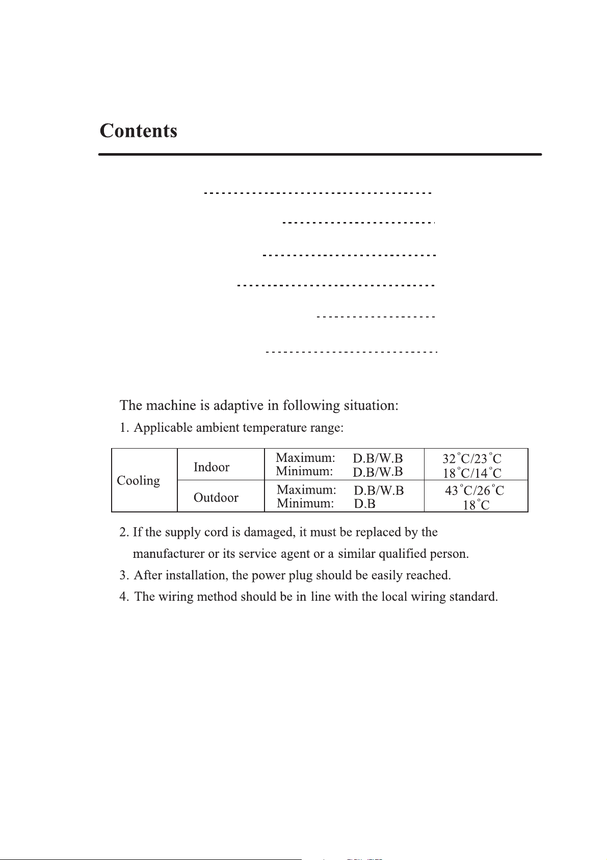
Contents
1
Parts and Functions
Operation Guide
Maintenance
Installation Instruction
Wiring Diagram
2-3
4-9
10-13
14-15
16
1
Page 3
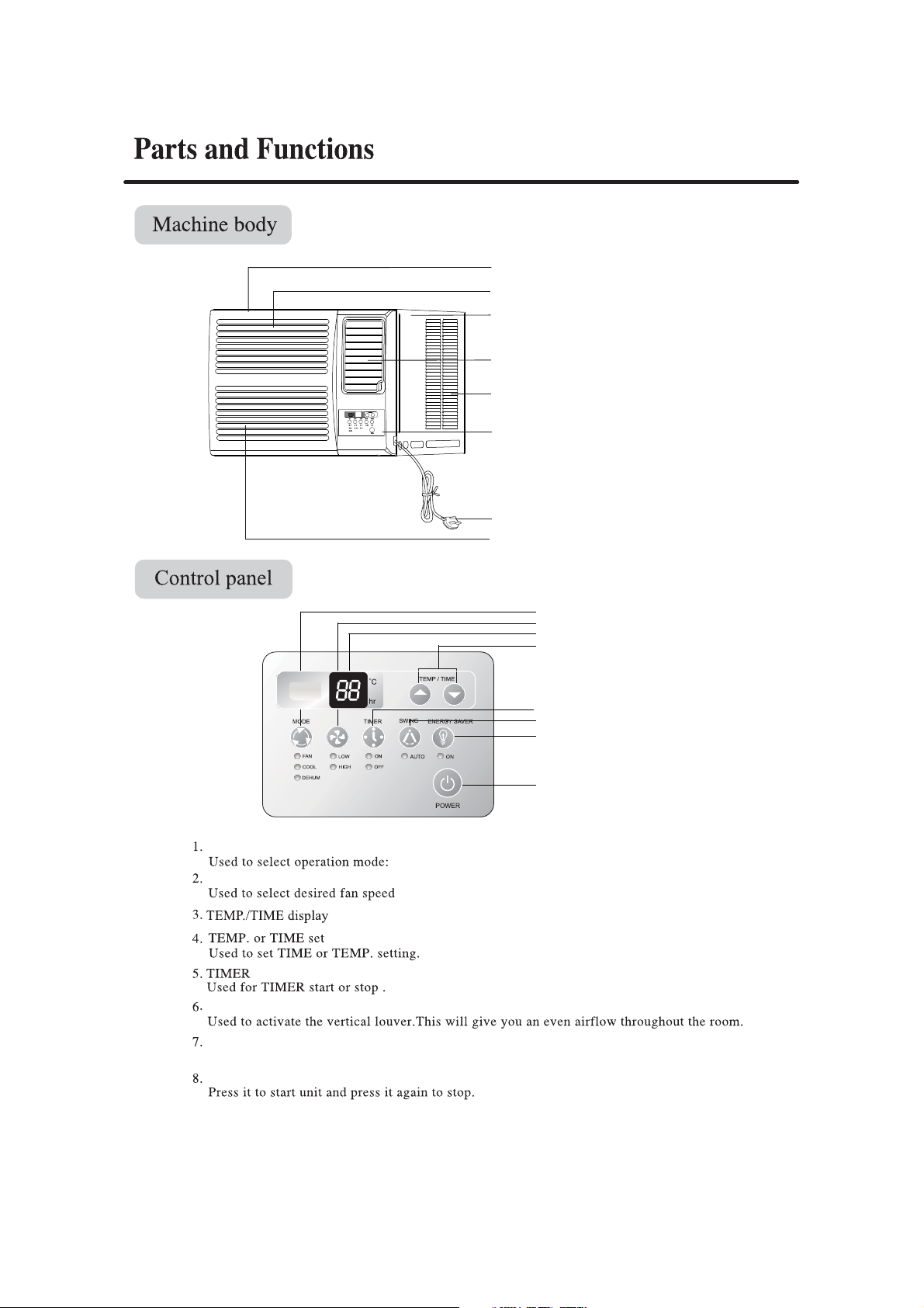
Front panel
Air inlet (indoor side)
Machine body
Air outlet (indoor side)
Air inlet (outdoor side)
MODE
FAN SPEED
FAN SPEED
FAN,COOL,DEHUM.
:HIGH or LOW.
Display
panel
Power plug
Air filter (inside)
1
2
3
4
5
6
7
8
SWING
ENERGY SAVER
Used to activate ENERGY SAVER option,reduce energy consumption and noise.
POWER
2
Page 4
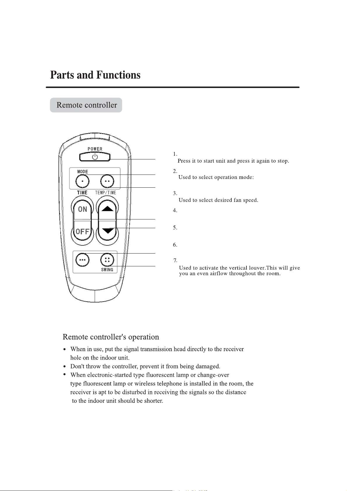
1
POWER
E-S
FAN SPEED
5
2
3
MODE
FAN,COOL,DEHUM.
FAN SPEED
TIMER button
4
5
Used for TIMER start or stop .
TEMP. or TIME set
Used to set TIME or TEMP . setting .
E-S
6
ENERGY SAVER
SWING
7
3
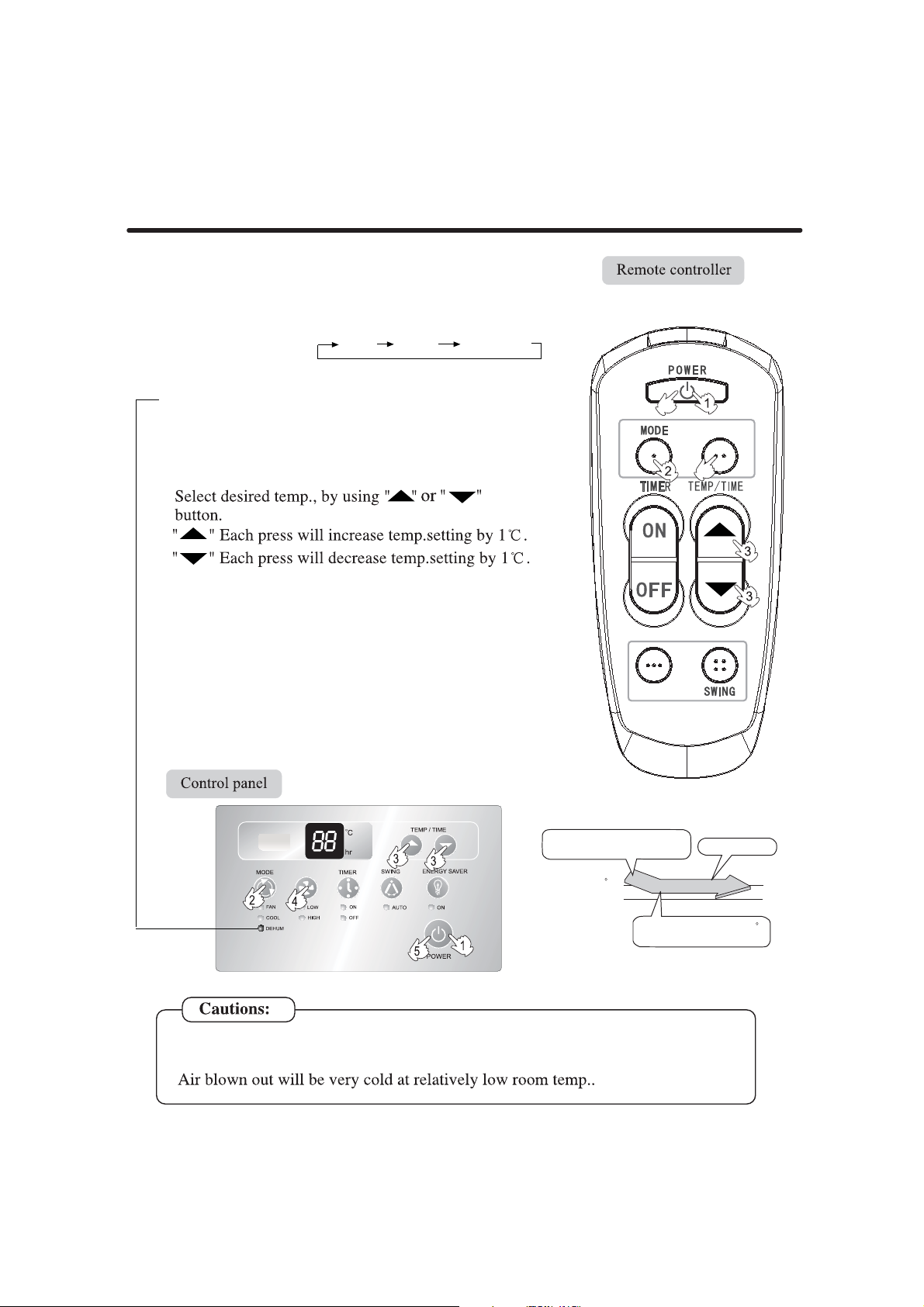
Page 5
COOL
1.Start
Press POWER button
2. Select operation mode
Press MODE button. For each press, operation mode
changes as follows:
Then select COOL operation.
When the COOL display lights bright, the unit will
be working under the cooling function.
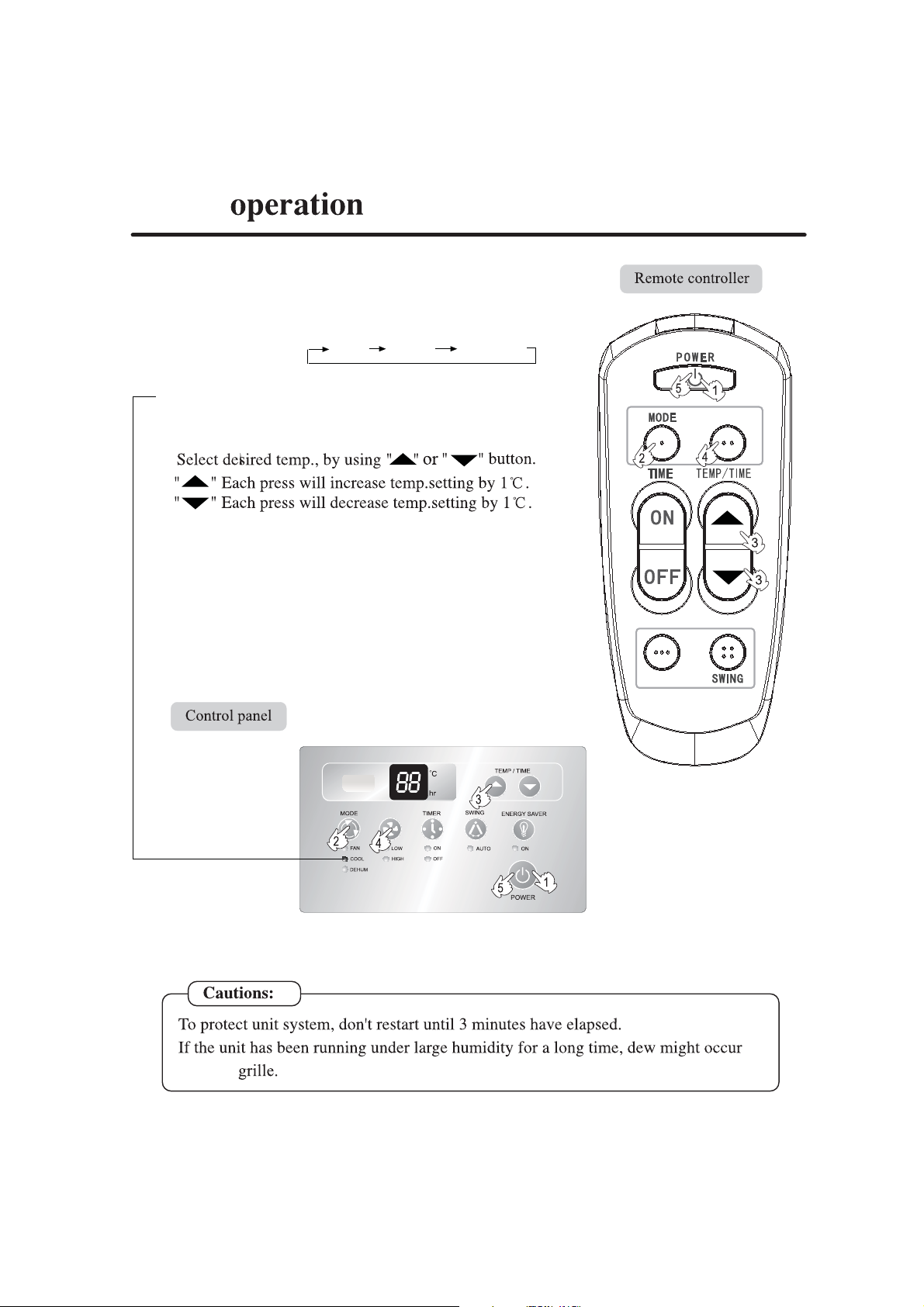
3. Select temp. setting
4. Fan speed selection
If you choose the FAN SPEED mode you can run the
fan in one of the 2 speeds: HIGH or LOW.
Select desired setting.
Change air flow direction if necessary.
5. Stop
Press POWER button again.
FAN COOL DEHUM
FAN SPEED
5
E-S
at outlet
FAN SPEED
4
Page 6
DEHUMID mode
1. Start
Press POWER button.
2. Select operation mode
Press MODE button. For each press, operation mode
changes as follows: FAN COOL DEHUM
Then select DEHUMID operation.
When the DEHUM display lights bright,The unit will be
working under the dehumidify function.
If you need to only remove the moisture press the
Dehnmid button. Change air flow direction if necessary.
5
FAN SPEED
3. Select temp. setting
4. Fan speed selection
If you choose the FAN SPEED mode you can run the
fan in one of the 2 speeds:HIGH OR LOW.
Air conditioner is running under displayed fan speed.
In DRY mode, when room temperature becomes
lower than temp.setting+2
o
C,unit will run intermittently
at LOW speed regardless of FAN setting.
5. Stop
3UHVV32:(5EXWWRQDJDLQ
FAN SPEED
E-S
COOL operation starts when room
temp.is higher than temp.setting.
Temp.setting+2 C
Temp.setting
4
Ultra-low air flow
The compressor may cycle for 10 minutes on and 6 minuters off in
Dehumid mode.
5
On reaching temp.setting +2 C
unit will run in mild DRY mode.
Page 7

FAN operation
1. Start
Press POWER button.
2. Select operation mode
Press MODE button. For each press, operation mode
changes as follows: FAN COOL DEHUM
Then select FAN operation.
When the FAN display lights bright ,the unit will be
working under the fan operation.
In some days you may want to run the FAN function.
Press the FAN button.
3. Fan speed selection
Here the fan runs only at HIGH or LOW speed.
Change air flow if necessary.
4. Stop
Press POWER button again.
4
FAN SPEED
FAN SPEED
E-S
4
6
Page 8

ENERGY SAVER operation
1. Start
Press POWER button.
2. Select operation mode
Press MODE button. For each press, operation mode
changes as follows: FAN COOL DEHUM
Then select COOL operation.
When the COOL display lights bright,the unit will
be working under the COOL function.
Saving energy function only can be used
when A/C working on cooling condition.
ENERGY SAVER selection
When this function is selected, the fan will
shut off three minutes after the compressor
cycles off. This will reduce energy consumption
and noise. When the compressor turns back on,
the fan will turn on at the same time. If this
function is not selected, the fan will not shut
off when the compressor cycles off.
4
FAN SPEED
4. Stop
Press POWER button again.
E-S
FAN SPEED
3
4
7
Page 9

On Off
24
coo
l
On Off
On
Press "On"of remote controller or "TIMER" of control panel,
Off
24
Press "Off"of remote controller or "TIMER"of control
TIMER ON
restarted
FAN SPEED
5
E-S
panel,
mode
FAN SPEED
8
Page 10

Power failure resume(please set and apply as necessary)
If sudden power failure occurs, the unit will resume original operation when power is supplied again.
Note:
When sudden power failure happens during unit operation in power failure resume mode, if the air
conditioner is not desired for use in a long period, please shut off the power supply in case that the
unit automatically resume operation when power is re-supplied, or press POWER to turn off the unit
when power resumes.
Operation
Adjusting of the air direction
Airflow Direction Vane
Vertical airflow direction
The Vertical Airflow Direction Vane is
manually controlled by positioning the
vane todischarge the air upward,
downward or straight out.
The horizontal air direction is adjusted
by setting the AUTO SWING ON .
Note:
It is advisable not to keep horizontal flap at downward position for a long
time in COOL or FAN mode, otherwise , condensate water might occur.
Don't move the vertical blade with hand in order to avoid the vertical blade
abnormal, using the remote controller to adjust the move of vertical blade.
9
Page 11

pulling
ush
" CLOSE" the vent door opens to allow air, smoke
or odors to be expelled from the room;
position
,
Pull
Pull
" OPEN"position, the vent door is closed and the air inside
the room is circulated and conditioned.
10
CLOSE
OPEN
Page 12

11
Page 13

Disposal of the condensed water
Generally there are two methods available on disposal of the condensed water:
1. Block the bottom plate hole of the conditioner with rubber lid, install outlet pipe fitting on the
back hole and let the condensing water flow from the back hole of the conditioner. (See Fig.1 )
In this method, the accumulated condensed water in the bottom plate is hit by the fan onto the
heat exchanger, and evaporated and blown out from the machine. It can cool the heat exchanger
radiator more quickly, and improve the energy efficiency of the conditioner. But the hitting noise
by the fan at the outdoor side is relatively large.
2. Block the back hole of the conditioner with rubber lid and install outlet pipe fitting to the bottom
hole, which can make the condensed water flow out from the bottom plate. (See Fig.2)
If necessary the above two methods can both have extra pipe added on the outlet pipe fitting.
(available on the market).
(Refer to P15 for choosing these two modes.)
Outlet
pipe fitting
Back hole
Fig.1
Rubber lid
Bottom plate hole
Rubber lid
Back hole
Outlet pipe fitting
Fig.2
Cautions
Power cord: Be sure to use the exclusive power cord.
Change installation place: If air-con need to be changed to another
place please contact the dealer, who sold you the unit.
Bottom plate hole
12
Page 14

13
Page 15

Name
Manual
Battery
(R-03 dry battery)
Outlet
pipe fitting
Sealed gasket
Rubber lid
Screw
Remote
controller
Figure
Quantity
(6
1
2
1
1
1
3
1
14
Page 16

MODEL
HW-09LN03
366mm 481mm
HW-12LN03
outlet pipe fitting
392mm 610mm
outlet pipe fitting
outlet pipe fitting
15
Page 17

Wiring Diagram
RECEIVING HEAD
TEMP.SENSOR
POWER SUPPLY
R:RED
B:BLACK
OR:ORANGE
BR:BROWN
BL:BLUE
Y/G:YELLOW/GREEN
WIRING DIAGRAM
LOUVER
MOTOR
CON1
BR
Y/G
BL
NOTE:1.Because of different compressor,the dotted
2.There are no dotted lines on some types.
M
B
BL
CN13
CN12
CN3
CN2
part may not be used.
(marked with @)
BR
BR
OR
CN11
COMP.RELAY
FAN MOTOR
M
L
H
M
B
R
#
CN9
CN8
4
3
BL
CN10
M
C
PROTECTOR
RBL
250V/3.15A
COMPRESSOR
S
R
B
CAPACITOR
BL
CN14
FUSE
0010511621
Circulation
3
Airflow(m /h)
HW-09LN03
HW-12LN03
Capacity(BTU)
9000
12000
Power input/
Rated power
input (W)
Current/Rated
current(A)
980/1500 4.4/6.9 360 1.0 29.5
1250/1600 6.5/8.5 450
Note: All capacities are gross.
Haier THERMOCOOL reserves the right to change
specifications as part of its policy of continuous improvement.
16
Dehumidification
Capacity(10.M/h)
Dimensions(indoor
unit) D*W*H(mm)
Net weight
(Kg)
531X471X356
1.2 37 Yes
560X600X382
12 Month
Guarantee
Yes
Page 18

With 3 years warranty on all air- conditioner compressors, you have
peace of mind from the date of purchase
-
-
NATIONWIDE SALES AND SERVICES
MINNA,ILORIN,OSHOGBO,LOKOJA,
sales office
7
2719790
-
-
-
Page 19

Page 20

 Loading...