

Hafler SE-120 Service Manual
THE
POWER AMPLIFIER
Hafler
SE120
SERVICE MANUAL
HAFLER
A DIVISION OF
ROCKFORD CORPORATlON
613 SOUTH
ROCKFORD
DRIVE
TEMPE,
ARIZONA 85281

SPECIFICATIONS
POWER RATING:
Less than 0.006% total harmonic distortion at any
power level up to 60 watts continuous average power per
8
channel into
20
kHz
with both channels driven.
IM
DISTORTION (IHF):
ohms at any frequency between 20 Hz and
Less than 0.005% from 1 to 60 watts, each channel,
into 8 ohms.
TYPICAL THD AT 60 WATTS INTO 8 OHMS:
20 Hz: 0.002%
1
kHz:
0.002%
20
kHz:
0.006%
FREQUENCY RESPONSE INTO
-3dB, 4Hz
+OdB,
to
2OOkHz
-0.5dB, 1OHz
at 1 watt.
to
4OkHz
8
OHMS:
at 60 watts.
TYPICAL CHANNEL SEPARATION:
2OHz: > 75dB
1kHz: > 85 dB
20kHz: > 65dB
SIGNAL TO NOISE RATIO, UNWEIGHTED:
Exceeds
1OOdB
referred to 60 watts into 8 ohms.
INPUT IMPEDANCE: 22,000 ohms
INPUT SENSITIVITY:
1.1 volts rms for 60 watts into 8 ohms.
Stereo/Mono Channel Operation:
The SE120 delivers 60 watts continuous average power per
channel into 8 ohms. It can be bridged for single channel
operation producing up to 120 watts of power into 16 ohms.
Input Mode Selector:
This switch will allow the user to specify the input signal to
the amplifier.
A. Stereo Mode:
This allows the right and left channels to reach their
designated amplifier channels. This mode will deliver
more than 60 watts into an 8 ohm load.
B. Mono Mode:
The SE1 20 can be operated in a bridged mode which drives
both channels with the same signal and combines to deliver
more than 150 watts into 8 ohms. This disables the right
channel input and routes the signal through the left channel.
Construction:
The simplified construction of the SE120 improves reliability and results in consistent performance. The heavy
duty case construction on the SE120 will provide years of
durability and trouble free protection.
Gold Plated RCA Input Connectors:
This provides the most accurate signal transmission and
lowest possible loss. Gold-plated terminals
are
immune to
signal deterioration with time that can be caused by corrosion in the connectors.
DAMPING FACTOR:
to
1kHz
into8ohms,50to
1OkHz
into8ohms.
100
POWER CONSUMPTION:
60 watts both channels into 8 ohms: 300 VA
Quiescent: 60 VA
SIZE:
3-1/4”
high plus
1/2”
feet,
17”
wide, 9” deep.
(83 mm high plus 152 mm, 432 mm wide,
229 mm deep.)
NET WEIGHT: 18 lbs. (8.2 kg)
SHIPPING WEIGHT: 20 lbs. (9.1 kg)
ALL SPECIFICATIONS SUBJECT TO CHANGE
WITHOUT NOTICE.
Copyright
1990.
All
rights
reserved
Speaker Output and Power Connectors:
For minimum loss power transfer, high definition and
oxidization resistance.
Protection System:
The SE120 is equipped with a unique protection system
that constantly monitors the temperature of the output
devices and takes corrective action to prevent damage to
the amplifier as a result of excessive overheating.
-l-
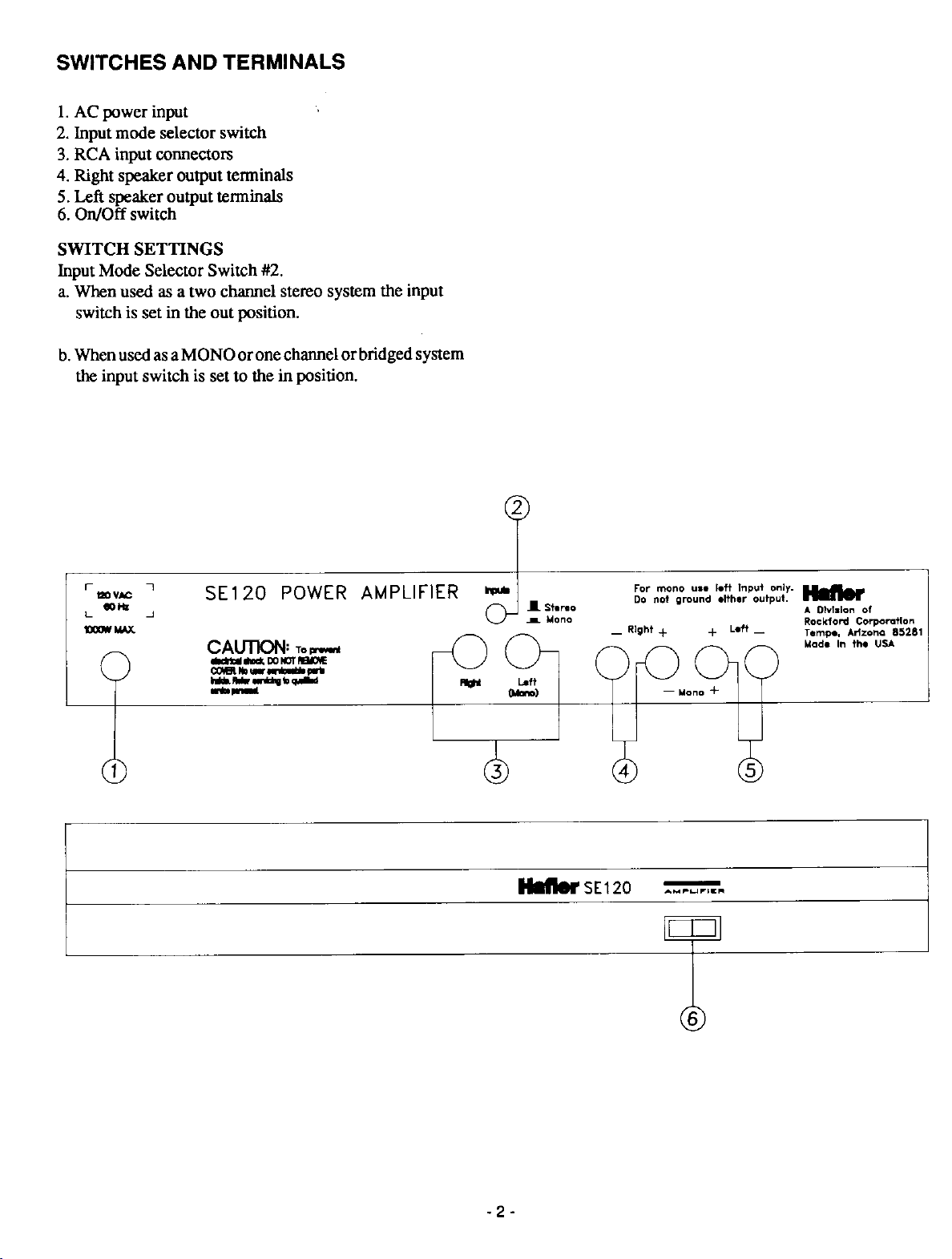

LINE CONNECTIONS AND SWITCHING
Standard #18 gauge lamp cord
#16
The SE120 is normally wired for use on
lines, as in the U.S.A. If your line voltage is different, you
will need the special Hafler export power transformer
which accommodates many other line voltages. Be sure
your amplifier is wired for your line voltage before you plug
it in.
The
SEl2O’s
amplifier switched remotely by connecting its line cord to
the preamplifier (or other control center) which provides a
switched AC outlet. Make sure that the control device can
supply a current of 5 amperes to the SE 120, in addition to the
current required by any other switched units. You may
instead connect the amplifier directly to a wall outlet, and
control it with its own front panel power switch.
power switch may be left on, and the
12OV
AC power
no frayed wire ends which could touch adjacent terminals
or the chassis. Tin bare wire ends with solder to secure all
strands.
PHASING:
necting speakers in order to enable full bass reproduction as
well as midrange and high frequency time alignment. To
be sure all speakers in a system are wired in phase to the
amplifier, each ground or - speaker terminal should be
connected to its black ground tenninal on the SE 120 and the
speakers + terminal to the corresponding red binding post.
Speaker connecting cable identifies one wire from the other
by the color of the wire, or by marking or coloring the
insulation. NOTE: In the special case of monophonic
operation of the SE 120, (described later) different speaker
connections are employed.
Consistent phase relationships are important when con-
CONNECTING CABLES
INPUT:
Conventional shielded cables, often supplied with preamplifiers, may connect the control center to the amplifier’s
input jacks. Be sure the cables are not frayed or loosely
connected to the plugs, and that the plug’s outer shield
connection is tight on the jack, to avoid hum. If you wish to
install the SE120 more than a few feet from the preamplifier, the permissible cable length to avoid loss of high
frequencies is determined by the preamplifier’s output impedance and the internal capacitance of the cable. If the
output impedance is 600 ohms or less, as with Hafler
preamplifiers, and the cable capacitance is less than
picofarads per foot, up to
stereo interconnecting cables often have higher capacitance, however, so a good quality low capacitance shielded
wire should be used. When making long runs, keep the left
and right cables close together, and avoid running them
parallel to power wiring to reduce the likelihood of hum
pickup.
OUTPUT:
The wires which connect the speakers to the amplifier
should be of sufficient size to
damping factor. is satisfac-
tory for up to 15 feet if your speakers are of 8 ohms or higher
impedance. A heavier gauge ( or larger) wire should be
used with 4 ohm speakers or 8 ohm speakers at a greater
distance. Special loudspeaker cables which have adequate
thickness to accommodate long runs are usually available
from audio dealers. The
accept standard banana plug connectors, including the
double ones with
ient to use if you will be disconnecting the speakers occasionally. The terminals will also clamp a spade lug, or a bare
wire through the hole in the center post. Be sure there are
3/4”
50-
feet is acceptable. Ordinary
preserve
SEl2O’s
spacing. These are the most conven-
the
SEl2O’s
red and black outputs
50
high
-3-
GROUNDING:
The black output terminals of the SE120 are connected
together internally and grounded to the chassis. This
facilitates the use of external devices which use a common
ground connection, such as some headphone junctionboxes.
You must be sure that the ground or shield connection from
such a device goes to a black terminal on the SE1 20.
NOTE: No such connection may be made when the SE120
is connected for bridged mono operation.
CONVENTIONAL STEREO
CONNECTIONS
It is best to make all connections with the SE120
switched off. Each of the stereo speakers connects to one
horizontal pair of red and black outputs, as identified left or
right on back of the SE 120. The input signals connect to the
corresponding input jacks, and the mono/stereo switch
should be set to stereo.
CONNECTIONS FOR MONOPHONIC
OPERATION
When you wish to drive a single loudspeaker with
increased power capability, the SE120 can be operated in
a bridged mode which drives both channels with the same
signal and combines their output to deliver more than 120
watts into 16 ohms. In this arrangement, the speaker is
connected only to the two red output terminals. The left red
terminal is + and the right red terminal is the - connection.
NO CONNECTIONS MAY
TERMINAL!! Set the Input Mode Selector switch to
mono, and connect the input signal to the left channel input
only. IMPORTANT NOTE: Never use a speaker with an
impedance of less than 8 ohms when operating the SE120
BE MADE
TO ANY BLACK
 Loading...