

Page 1
Hafler
INSTALLATION
fbd
OPERATION
Please refer to this serial
number in all communications
regarding this equipment.
Page 2

SPECIFICATIONS INTRODUCTION
8
OHM POWER RATING: 325 watts continuous aver-
age power per channel at less than
.025%
total harmonic
distortion from
2OHz
to 20kHz with both channels driven.
4 OHM POWER RATING: 450 watts continuous average power per channel at less than
.035%
total harmonic
distortion from
2OHz
to 20kHz with both channels driven.
8
OHM BRIDGED POWER RATING:
900 watts continuous average power at less than 0.035%
total harmonic distortion from
2OHz
to
2OkHz.
IM DISTORTION (IHF):
Less than .O 1% from 1 watt to 325 watts, both channels
into
8
ohms.
FREQUENCY RESPONSE INTO
8
OHMS:
-3dB, 4Hz
and
1OOkHz
at 1 watt
-.5dB, 1OHz
and 40kHz at 1 watt
SIGNAL TO NOISE RATIO, UNWEIGHTED:
Exceeds 95dB referred to 325 watts into 8 ohms,
100 dB (A-weighted)
TYPICAL CHANNEL SEPARATION:
2OHz: >
80dB
1kHz: >
75dB
20kHz:
> 6OdB
DAMPING FACTOR: 300 up to
1kHz
into 8 ohms.,
200upto
1OkHz
into8ohms.
SLEW RATE: 1
kHz, 12OV
p-p square wave: 40 volts
per microsecond.
VOLTAGE GAIN: 29dB
INPUT IMPEDANCE: 47,000 ohms, balanced
INPUT SENSITIVITY: 1.95 volts rms per phase for
325 watts into
8
ohms.
POWER CONSUMPTION:
12OV 6OHz
Line:
325 watts into 8 ohms both channels:
132OVA
450 watts into 4 ohms both channels:
18OOVA
SIZE: 3-
1/2”
high,
19”
wide,
14”
deep behind faceplate,
l-1/2” in front of faceplate including handles
NET WEIGHT: 40 lbs.
SHIPPING WEIGHT: 42
lbs.
ALL SPECIFICATIONS SUBJECT TO CHANGE
WITHOUT NOTICE.
The Hafler PRO5000 is a high power, low profile, two
channel power amplifier intended for professional sound
installations. It is the result of modern packaging combined
with the performance and reliability characteristics found
in previous Hafler designs. The PRO5000 has an optimized
combination of features needed for a professional power
amplifier: high power, small package size, rugged case
construction, balanced inputs, full bridgeability for mono
applications, continuously variable DC fan for quiet operation, and a variety of simple, yet effective protection
systems. Above all, however, the PRO5000 maintains the
well known
Hafler
tradition of superior sounding power
amplifiers.
OVERVIEW OF AMPLIFIER
The PRO5000 is a standard two-rack height fan cooled
design utilizing fully complimentary drive circuits and
lateral type MOSFET output transistors. The amplifier has
full subtractor balanced input circuits for good noise rejection. The drive circuitry is a high performance arrangement
with a double differential JFET input stage. Film capacitors
are used throughout the circuitry to ensure minimum degradation of the audio signal.
The 19” extruded aluminum front panel includes handles
for ease of installation, separate gain controls for each
channel, signal present and clipping indicators for both
channels, and the power switch which has a pilot lamp. The
rear panel has both
1/4”
phone and XLR connectors for the
inputs,
5-way
binding posts for the outputs, a switch to
bridge the amp for mono mode. and a switch to connect or
disconnect the audio ground from the chassis ground.
The protection systems include separate power supply
fuses on DCV+ and
DCV-
for each channel, thermal
sensing circuits that monitor output device temperature and
correspondingly control the DC fan, a relay to disengage
the load if excessive DC offset is detected or if the output
device temperature becomes too high, a delay to avoid
dangerous turn-on/off transients, and an AC line fuse if all
else fails. This amplifier does not have, and by virtue of
design, does not need the current limiting circuits which are
required to protect conventional bipolar or vertical MOSFET
output devices. The less common lateral
MOSFETs
used in
Hafler
amplifiers inherently limit the current ONLY under
abnormal conditions, thus avoiding ‘thermal runaway’ and
subsequent device destruction. This gives the dual advantage of greater reliability from simpler circuitry, and the
elimination of one of the chief causes of distorted signals
the harsh sounds of the actuation of complex protective
circuits.
-l-
Page 3

1.
Read Instructions
AII
the safety and operating instructions of your
Hafler
equipment should be read before power is applied to
the equipment.
2.
Retain Instructions
These safety and operating instructions should be held
for future reference.
3.
Heed Warnings
All warnings on the equipment and in the operating
instructions are important and should be followed.
4.
Follow instructions
All operating and use instructions are important and
should be followed.
5.
Heat
The equipment should be kept away from areas of high
temperature, such as heater vents, radiators, stoves/
ovens, fireplaces, etc.
6.
Ventilation
The equipment should be used in an area suitable for
proper ventilation. Care should be taken to not impede
airflow in and around the cabinet. Do not mount on a
carpeted shelf or in an enclosure consisting of more than
five sides. Allow for proper clearance above the equipment.
7.
Water and Moisture
8.
The equipment should not be used in or around water
such as a bathtub, sink, or swimming area. Also, the
equipment should not be used in areas prone to flooding
-
such as a basement.
Power Sources
The equipment should be connected only to a power
source of the same voltage and frequency as that listed
on the rear panel near the power cord entry point.
9.
Power Cord Protection
NOTICE - IMPORTANT SAFETY INFORMATION
DO NOT DISPOSE OF - KEEP FOR FUTURE REFERENCE
Safety Instructions
Power cords should be run so that they do not interfere
with the movement of
objects
in the room - people, fan
blades, utility carts, etc. Also, care should be taken that
the cord is not pinched or cut, and placed so that it is not
in danger of being pinched or cut, as in under a rug,
around a tight corner, etc.
10.
11.
12.
13.
14.
15.
Grounding and Polarization
The power supply cord is of a polarized type designed
to reduce the risk of electric shock sustained from a live
cabinet. It is assumed to be of a suitable length for most
uses of the equipment. The use of extension cords and
power strips is discouraged unless they are of suitable
rating to deliver the required current for safe equipment
operation and can be used so that the polarization of
the plug is not defeated. If an extension cord is required,
it is important that the blades of the plug be able to insert
fully into the receptacle. Professional amplifiers with a
S-conductor line cord must never have the ground pin
of the plug defeated.
Non-Use Periods
During extended periods of non-use the power supply
cord should be kept unplugged from the power source.
Cleaning
The equipment should be cleaned only as detailed by
the owners manual.
Object
and Liquid Entry
Care should be taken so that
objects
and/or liquids,
such as cleaning fluids, are not spilled into the enclosure
of the equipment.
Damage Requiring Service
HafIer
equipment should be serviced by qualified ser-
vice personnel when:
A.
B.
C.
D.
E.
The power supply cord or plug has been
damaged; or
Objects
have fallen, or liquid has been spilled
into the equipment; or
The equipment has been exposed to rain; or
The equipment does not appear to operate
normally or exhibits a marked change in performance; or
The equipment has been dropped, or the enclosure damaged.
Servicing
The user should not attempt to service the equipment
beyond that which is described in the manual. All other
service
should be referred to qualified service person-
nel.
-2-
Page 4
16. Carts and Stands
The equipment should be used only with a cart or stand
of sufficient strength and stability for the use intended.
16A.
An equipment and cart combination should be moved
with care. Quick stops, excessive force, and uneven
surfaces may cause the equipment and cart combination
to topple.
17. Power Lines
An outdoor antenna should be located away from power
lines.
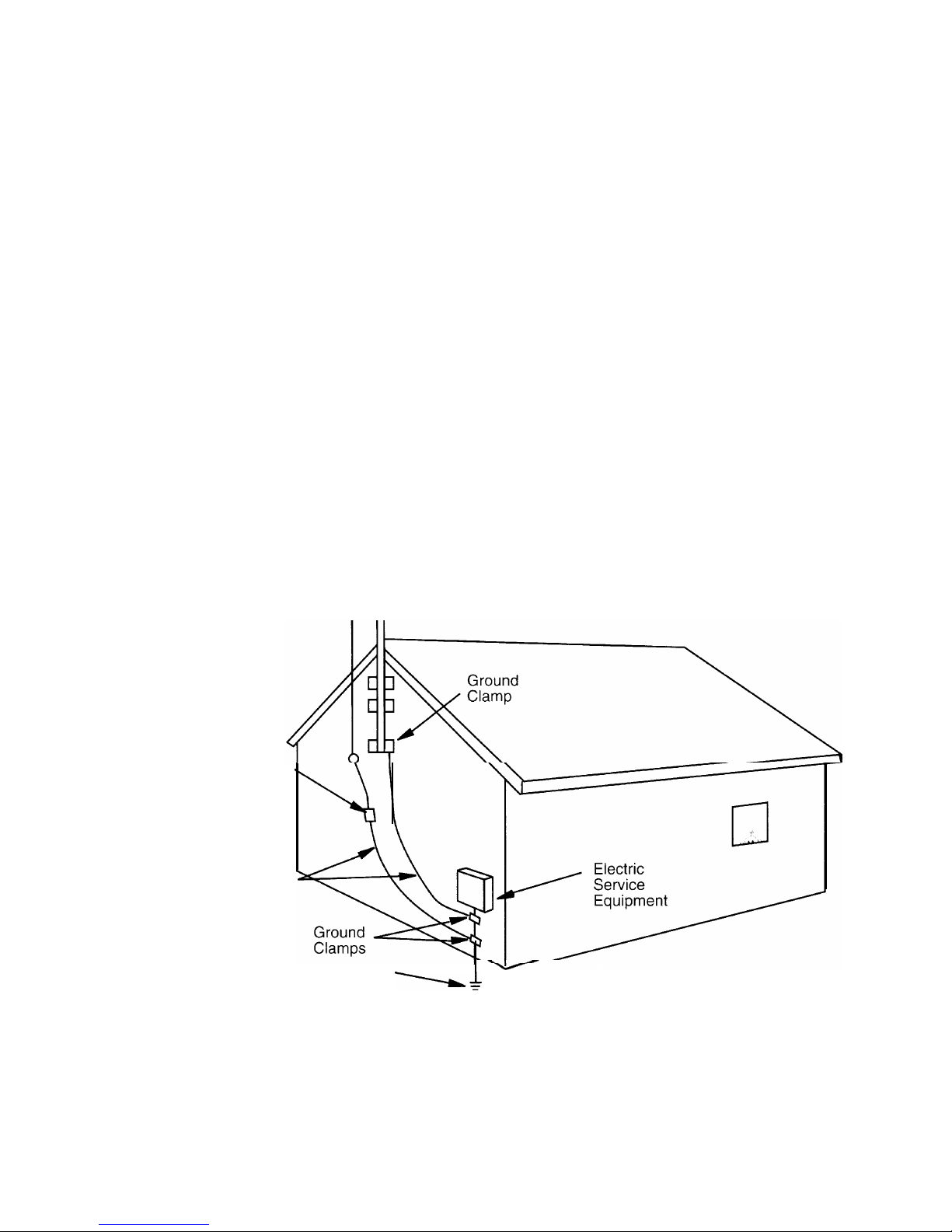
18.
Outdoor Antenna Grounding
If an outside antenna is to be used with the
HafIer
Tuner,
be sure that the antenna system is grounded so as to
provide some protection against voltage surges and built
up static charges. Section 8 10 of the National
Electrical
Code,
ANSl/NFPA
No.
70-
1984,
provides information
with respect to the proper grounding of the mast and
supporting structure, grounding of the lead-in wire to an
antenna discharge unit, size of grounding conductors,
location of antenna discharge unit, connections to
grounding electrodes, and requirements for the grounding electrode. See Figure
1.
EXAMPLE OF ANTENNA GROUNDING AS
PER NATIONAL ELECTRICAL CODE
Antenna
Lead In
Wire
7
Antenna
Discharge Unit
.
(NEC Section 810-20)
Grounding Conductors
(NEC Section 810-21)
Power Service
Grounding
\+
Electrode System
(NEC Art 250, Part H)
FIGURE 1
-3-
Page 5

INSTALLATION
MOUNTING
The front panel is designed to fit a standard
19”
rack at 3-
l/
2” intervals or alternatively the unit may be stacked. NOTE:
When rack mounting the
PRO5000,
the rear of the amplifier
must be fastened to the rack via the rear mounting holes to
eliminate large torque forces on the faceplate. The feet may
be removed if desired when rack mounting.
VENTILATION
Do not block the air flow into or out of the amplifier. Air is
drawn in through the vents in the front panel, and is
exhausted out the side vents. Therefore, when rack mounting
in a cabinet, allow sufficient space between the inside walls
of the rack and the amplifier chassis, (at least 2 inches). If
the cabinet has a front door, the door must have large enough
vents to allow enough volume air flow for each amplifier in
the rack, (80 CFM per PRO5000 should be adequate). A
good alternative is to augment the air flow with a rack
mounted fan that pressurizes the space in front of the
amplifiers and/or evacuates the air space in the rear of the
cabinet.
The PRO5000 includes a removable dust filter assembly
attached to the outside of the front intake vents. This filter
should be removed occasionally and cleaned. To remove,
gently squeeze the ends inward and pull the filter frame
straight out from the front panel. The foam filter element
may then be removed from the frame and shaken or blown
out with compressed air. If the foam is particularly dirty, it
may be washed with mild soap and warm water. Replacement foam elements are available from the factory, part
number HWH-392.
CONNECTIONS
AC LINE CORD:
High power output puts heavy demands on the AC supply
to the amplifier. A single PRO5000 delivering 4 ohm rated
power will heavily load a typical 15 amp circuit. Multiple
amplifiers will need to be connected to a circuit capable of
delivering the required current (see specifications), in order
for the amplifiers to produce the expected audio power.
The PRO5000 is normally wired for
12OV 6OHz
operation,
as in the USA. The transformer can be rewired to accommodate other line voltages upon request. Note that the value
of the internal AC line fuse (near the power switch), should
be changed when converting from lower line voltages
(
12OV
or less use a 15 amp Slo-Blo), to higher line voltages
(200V and up use a
7-1/2
amp Slo-Blo). Never wire the
amplifier for a lower line voltage than what is supplied in an
attempt to obtain greater output power. Such an attempt will
very likely damage parts in the amplifier not rated for the
higher voltages that will result, and the warranty will be
voided.
A
3-wire
grounded power cord is supplied. It must be
connected to a properly grounded (earthed) AC receptacle
for safety. Do not break off the ground pin on the plug to
avoid using the proper adapter for
2-wire
receptacles.
SIGNAL INPUT:
Both
1/4”
phone and XLR balanced connectors are provided on the back panel. These connectors are wired in
parallel for each channel, so that either may be used with no
further switching. The unused connector may be used to
“daisy chain” other amplifiers from the same source using
the appropriate cables.
To achieve maximum noise rejection, balanced lines should
be used for the inputs (two out-of-phase polarity signal
conductors plus a ground shield). The XLR connectors are
wired for the IEC international standard, which connects
the #1 pin to the ground shield; the
#2
pin as the
noninverting or ‘hot’ signal; and the #3 pin as the inverting or
‘return’ signal. The phone jacks are wired with the sleeve
as the ground shield; the tip as the non-inverting signal; and
the ring as the inverting signal. Note that in other equipment the two signal connectors are sometimes interchanged
from what is stated here-it is therefore wise to check for
consistency among the equipment being installed.
For an unbalanced input line (one signal conductor and a
ground shield), connect the signal conductor to the
noninverting input, and connect the ground shield to the input
ground AND the inverting input of the amplifier. Note that
with a two conductor
1/4”
phone jack, this connection is
automatically made, assuming that the sleeve (which is
longer than that of a three circuit phone jack and includes
the ring) is the ground shield and the tip is the signal. In this
case, simply insert the phone jack fully into the input of the
amplifier.
For bridged mono operation, only use the channel A input
and set the mono/stereo switch to mono. Make no connection to the channel B input jacks. In this mode the channel
A gain control determines the gain of the amplifier. See
below for a description of loudspeaker connection in this
mode.
To prevent noise or hum, it is essential that all input
connections are secure, and that the cables are not frayed or
loosely connected to the plug.
OUTPUT:
The red and black binding posts will accept a variety of
speaker lead terminations, the most convenient of which
-4-
Page 6

are the ‘banana’ plug connectors with
3/4”
spacing. Bare
wire can be inserted through the vertical holes in the shafts,
which are visible when the caps are unscrewed. To be
certain that no strands of wire are unsecured, it is best to tin
the wire end before insertion. Alternatively, a spade lug
soldered
to the wire end will make a good connection.
Make all connections between loudspeakers and the amplifier with the power shut off to avoid loudspeaker damage.
Select wire of sufficient size to preserve the high damping
factor of the
PRO5000.
The minimum recommended wire
size is #1
6
gauge when high power output is expected.
Larger wire sizes are necessary for long runs, or if the
speaker impedance is less than
8
ohm.
PHASING:
Consistent phase relationships are important when connecting speakers in order to enable full bass reproduction as
well as midrange and high frequency time alignment. To be
sure all speakers in a system are wired in phase to the
amplifier, each
ground or - speaker terminal should be
connected to its black ground terminal on the
PRO5000,
and the speakers + terminal to the corresponding red
terminal. Speaker connecting cable identifies one wire
from the other by color of the wire, or by marking or
coloring the insulation. NOTE: In the special case of
monophonic operation of the
PRO5000,
(described below)
different speaker connections are employed.
GROUNDING
The black output terminals of the PROS000 are connected
together internally and grounded to the chassis. This facilitates the use of external devices which use a common
ground connection, such as some headphone junction boxes.
You must be sure that the ground or shield connection from
such a device goes to a black terminal on the
PRO5000.
NOTE: No such connection may be made when the
PROS000 is connected for bridged mono operation.
The back panel of the PRO5000 also contains a chassis/
float groundswitch forground isolation. This switch should
be set for minimum system hum and/or noise.
BRIDGED MONO OPERATION:
To drive a single loudspeaker with increased power capability, the PRO5000 can be operated in the bridged mode
which drives both channels with the same signal and
combines their output to deliver more than 900 watts to an
8
ohm speaker. In this arrangement, the speaker is connected only to the two red output terminals. The channel A
terminal is the
"+",
and the channel B terminal is the
"-"
connection. No connections should be made to either black
output terminal in this configuration.
OPERATION
APPLYING POWER:
Standard practice is to turn power amplifiers on last and off
first in the chain of electronics. This minimizes the likelihood of damage to the load from turn-on and turn-off
transients generated by source equipment. The PROS000
provides built-in protection from such transients by incorporating a delay of approximately 3 seconds before the
relay connects the loudspeakers. If a longer delay is required, contact the
Hafler
Technical Service Department.
The pilot lamp in the power switch will glow whenever
power is applied to the
PRO5OOO.
If it does not light, check
for a blown internal AC line fuse. Otherwise, check the line
circuit breaker for a fault.
FRONT PANEL INDICATORS:
The presence of any signal above the noise
floor
will
activate the green ‘Signal’ lights for each channel. The red
‘Clip’ indicators are activated by a comparator circuit which
triggers when the output distortion level reaches approximately 3%. They indicate when the demands of the amplifier exceed its output capability. Because the dynamics of
good source material may include steep waveforms which
reach these limits for a small fraction of a second, normal
actuation would cause them to flicker so briefly that the eye
would miss it. In the interest of giving maximum information, a “hold” circuit is included which extends these brief
pulses to about
1/4
of a second, so they will be clearly
visible. However, these occasional flashes do not indicate
that the amplifier is being substantially overdriven. Thus,
these lamps may operate quite differently from similarly
marked indicators on other amplifiers.
GAIN CONTROLS:
The gain controls for each channel are precision potenti-
ometers, designed for very low distortion. Unless there is a
specific purpose for an intermediate setting (such as level
matching), the gain controls are usually fully advanced
clockwise. This is the setting for which the amplifier’s
sensitivity and voltage gain are specified. Note that in the
bridged mono mode, the channel A control determines the
gain of the amplifier.
DC OFFSET:
If at any time the DC voltage rises to an unsafe level at the
outputs. the relay will disconnect the loudspeakers from the
amplifier. It should be noted that very high levels of low
frequency energy can sometimes imitate DC at the output,
and might activate the relay protection inappropriately. If
this becomes a problem, the level of DC protection provided
can be changed by consulting the
factory.
Page 7

PRO 5000 FUNCTIONAL BLOCK DIAGRAM
TEMPERATURE
SENSORS
-1
FAN
SPEED
CONTROL
RELAY/
RELAY
\
TIMER
KICKOUT
/’
OFFSET
’
DETECTOR
OUTPUT
SIGNAL
DETECTOR
c
’ --,
, ; LIGHT
lo’
s’G
DESIGNATOR PART DESCRIPTION
T201
Transformer
DB201
Diode Bridge
F201
10A Fuse
SW201 Power Switch
SW202 Grounding Switch
C201, C202
Capacitor 20,000
C203
Capacitor .01 (UL approved)
C204
Capacitor
.01
TS201
Inrush Limiter
J201 (J203)
Binding Post, Black
J202 (J204)
Binding Post, Red
CLIP
>
DETECTOR
<
CHASSIS PARTS LIST
PART
#
TT-PRO5000
SSH-609
FS-010
SWH-144
SWH-103
CER-209
CD-103A
CD-103/20
SSH-618
CCH-1
10B
CCH-1
1OR
-6-
Page 8

Page 9

Page 10

PRO 5000 PARTS LIST
DESIGNATOR
PART DESCRIPTION
DESIGNATOR:
“B”
Channel
(“A”
Channel)
PART
#
DESIGNATOR
PART DESCRIPTION PART
#
(Cl)
Cl9
(C2)
c20 (C3)
CZl (C4)
c22
(C5)
C23 (C6)
C24
(C7)
c25 (C8)
C26
(C9)
C27 (CID)
C28 (Cll)
c29
(Cl2)
c30 (Cl3)
c31 (Cl4)
C32
(Cl5)
c33
(Cl6)
c34
(Cl7)
c35 (Cl8)
C37
(C36)
C42
(C38)
c43
(C39)
c44
(C40)
c45
(C41)
c52 (C46)
c53 (C47)
c54
(C48)
c55
(C49)
C56
(C50)
c57
(C51)
C58
c59
C60
C61
C62
C63
C64
C65
C66
C67
C68
CR7
(CRl)
CR8
(CR2)
CR9
(CR3)
CR10
(CFi4)
CR31
(CR5)
CR12
(CR6)
CR13
CR14
CR19
(CRi5)
CR20
(CRl6)
CR21 (CRl7)
CR22 (CRl8)
CR23
CR24
CR25
CR26
CR27
CR28
Unused number
330
pfd,
Polypropylene
10 pfd
Dipped MIca
1 mfd, Polycarbonate
1000 mfd, Non-Polar
001 mfd, Polypropylene
001 mfd, Polypropylene
220
pfd,
Polypropylene
1
mfd,
Polycarbonate
1
mfd,
Polycarbonate
1
mfd, Polycarbonate
100 mfd,
Electrolytic
100 mfd,
Electrolytic
I mfd,
Polycarbonate
1 mfd. Polycarbonate
01
mfd Polycarbonate
I
mfd, Polycarbonate
Unused number
680
pfd, Dipped Mica
680 pfd, Dipped Mica
680
pfd, Dipped Mica
47 mfd, Polyester
47 mfd Polyester
4 7 rnfd
ElectrolytIc
33 mfd Polyester
4 7 mfd, Non-Polar
33 mfd Polyester
033 mfd, Polypropylene
1 mfd. Polyester
39
mfd,
Polyester
39 mfd, Polyester
39 mfd Polyester
1 mfd Non-Polar
1
mfd, Electrolytic
1
mfd,
V-Series
1
mfd,
V-Series
1000
mfd,
Electrolytic
1000 mfd,
ElectrolytIc
10 mfd,
ElectrolytIc
10
mfd,
ElectrolytIc
FDH400 Diode
FDH400
Diode
1
N4148 Diode
1 N5245B Zener
Diode, 15V
1
N5245B
Zener
Diode, 1%
1 N4 148
Diode
1 N4
148
Diode
1
N4148
Diode
MV5754S LED Green
1 N4 148
Diode
1 N4 148
Diode
MV64530
LED, Red
1N4148
Diode
1
N4148
Diode
I
N4003
Diode
1
N4003 Diode
1
N4003
Diode
1
N4003
Diode
F3
(Fl)
Fuse
1OA
F4
(F2)
Fuse
1OA
FM1
Fan
L2
(Ll)
P2
(Pl)
P4
(P3)
P6
(P5)
P8
(P7)
Q21 (Ql)
a22 (Q2)
U23 (Q3)
Q24 (Q4)
Q25
(Q5)
Q26 (Q6)
Q27 (Q7)
Q28
@3)
Q29 (Q9)
Q30
(QlO)
Q31 (Qll)
Q32
(Ql2)
Q33
(Ql3)
Q34
(Qi4)
Q35
(Qi5)
Q36
(Ql6)
Q37
(Ql7)
Q38
(Ql8)
Q39
(Ql9)
Q40 (Q20)
Q43 (Q41)
Q44 (Q42)
Q45
Q46
Q47
Inductor
I
4
mH
Pot 1000 Ohm
Trimmer
Pot 500 Ohm
Trimmer
Pot 5000 Ohm Volume
Pot 500 Ohm
Trimmer
2SKl63
N-Channel JFET
2SKl63
N-Channel JFET
2SJ74
P-Channel JFET
2SJ74
P-Channel JFET
2N5550 BI
Polar
2N5550
Bi-Polar
2N5401
Bi-Polar
2N5401
Bi-Polar
ZN5401
Bi-Polar
2N5550
Bl-Polar
2N5415
Bi-Polar
2N3440
Bi-Polar
2N2222 Bi-Polar
2N3440
Bi-Polar
2N5415 Bf-Polar
2SKl76
N-Channel MOSFET
2SKl76
N-Channel MOSFET
2SJ56
P-Channel MOSFET
2SJ.56 P-Channel MOSFET
Unused Number
2SKl76
N-Channel MOSFET
2SJ56
P-Channel MOSFET
MPSA06 Bl-Polar
MPSA06 Bl-Polar
2N6490
Bl-Polar
Fl36
(Rl)
R37
(R2)
R38 (R3)
R39
(R4)
R40
(R5)
R41
(R6)
I?42
(R7)
R43 (Ra)
R44
(R9)
R45
(RIO)
R46
(Rll)
R47
(Rl2)
R48 (Rl3)
2
43k
Ohm,
1/4w,
Ia0
47 5k Ohm,
1/4w.
1%
47 Ohm
lf4w. 500
47 Ohm
1/4w, 500
68 Ohm
1/4w, 500
47 Ohm
1/4w, 500
47 Ohm,
114~ 500
1000
Ohm,
1/4w, lo~0
1000 Ohm,
1/4w? 1%
6 8k Ohm,
1/4w, 500
47 5k Ohm
114~. 1%
2 43k Ohm,
1/4w,
lo0
270 Ohm,
1/4w 500
CPP-331
CM-100
CPC-104
CERNP-108
CPP-102
CPP-102
CPP-221
CPC-104
CPC-104
CPC-104
CER-107D
CER-1 07D
CPC-104
CPC-104
CPP-1 03A
CPC-1
04
CM-681
CM-681
CM-681
CP-474
CP-474
CER-475B
CP-334
CERNP-475A
CP-334
CPP-333
CP-104A
CP-394E
CP-394E
CP-394E
CERNP-105A
CER-105C
cv-104
cv-104
CER-108B
CER-108B
CER-106
CER-106
SS-163
SS-163
SS-162
ss-212
ss-212
SS-162
SS-162
SS-162
SSH-704
SS-162
SS-162
SSH-706
SS-162
SS-162
SS-161
SS-161
SS-161
SS-161
FS-010
FS-010
FAN-P5000
l-r-l 4
RV-1
02
RVH-501 A
RV-502D
RVH-501 A
SSH-614T
SSH-614T
SSH-617DT
SSH-617DT
SSH-613
SSH-613
SSH-708
SSH-708
SSH-708
SSH-613
SSH-616
SSH-612
SSH-611
SSH-612
SSH-616
SSH-607
SSH-607
SSH-608
SSH-608
SSH-607
SSH-608
SS-102A
SS-102A
ss-113
RMP/4-2431
RMP/4-4752
RC/4-470
RC/4-470
RC/4-680
RC/4-470
RC/4-470
RMP/4-1001
RMP/4-1001
RC/4-682
RMP/4-4752
RMP/4-2431
RC/4-271
R49
(Rl4)
R50 (Rl5)
R51 (Rl6)
R52
(Rl7)
R53 (Rl8)
R54 (Rl9)
R55 (RZO)
R56
(R21)
R57
(R22)
R58
(R23)
R59
(R24)
R60
(R25)
R61
(R26)
R62
(R27)
R63
(R28)
R64
(R29)
R65
(R30)
R66
(R31)
R67
(R32)
R68 (R33)
R69
(R34)
R70
(R35)
R71
R72
R73
R74
R75
R76
R77
R78
R79
R80
R81
R82
R85
(R83)
R86
(R84)
RlOO
(R87)
RIO1
(R88)
RIO2 (R89)
R103 (R90)
R104
(R91)
RlO5
(R92)
RIO6
(R93)
RIO7
(R94)
RIO8
(R95)
RlO9 (R96)
RI10
(R97)
RI11
(R98)
RI12
(R99)
RI29 (Rll3)
RI30 (Rll4)
RI31 (Rll5)
RI32 (Rll6)
R133
(Rll7)
Rl34 (Ril8)
Rl35 (Ril9)
Rl36 (Rl20)
Rl37 (Rl21)
Rl38
(Rl22)
Rl39 (Rl23)
Rl40
(Rl24)
Rl41 (Rl25)
Rl42
(Rl26)
Rl43
(Rl27)
Rl44 (Rl28)
Rl45
RI46
R147
Rl48
RI49
RI50
RI51
R152
R153
Rl54
Rl55
Rl56
Rl57
Rl5a
Rl59
Rl60
Rl61
R162
R163
Rl64
Rl65
SW1
SW2
TS2
(TSI)
Ul
u3
(U2)
u4
u7
vJ5)
U6
U8
u9
UlO
J4
CJ2)
J3
CJl)
J5
J6
J7
J8
J9
270 Ohm,
1/4w,
5%
1000 Ohm,
114~~
5%
1000 Ohm,
114~~
5%
100 Ohm,
1/4w, 500
100 Ohm,
1/4w, 500
47k Ohm, 1/4w.
5”&
560 Ohm,
l/4w,
5%
470 Ohm,
1/4w,
5%
10 Ohm,
1/4w,
5%
47 Ohm,
1/4w, 50f0,
Carbon
47
Ohms 1/4w,
5% Carbon
220 Ohm,
1/4w, 5%
470 Ohm,
1/2w, 5%
470 Ohm, 1/2w, 5%
220 Ohm,
1/2w, 5Ob
220 Ohm,
1/2w, 500
10 Ohm,
1/4w, 500
I
Ohm,
low,
5%
IO
Ohm. 5w
5’1~
47k Ohm, 1/4w,
5%
33k
Ohm? 1/4w, 5%
47k
Ohm? 1/4w, 500
47k
Ohm< 1/4w, 500
82k
Ohm,
1/4w, 5%
220k Ohm,
1/4w,
5%
15 8k
Ohm,
1/4w, lo0
82 5k Ohm, 1/4w, lo0
33k Ohm, 1/4w, 5%
2 2k Ohm, 1/4w,
50!,
1Ok
Ohm.
1/4w,
5%
1 k Ohm,
1/4w 500
51 1 k Ohm,
1/4w,
1%
681 k Ohm,
1/4w,
1%
681 k Ohm,
1/4w, lo0
470 Ohm 1/2w,
5%
220 Ohm 1/2w,
500
2 2k Ohm. 1/4w
5O&
2 2k Ohm,
1[4w, !?i”jO
47k Ohm,
114~. 500
47k Ohm,
1/4w 500
1OOk
Ohm,
114~.
5%
1OOk
Ohm,
114~.
5%
1 lk Ohm,
1/4w,
lo0
39k Ohm,
1/4w. 5%
11 k Ohm,
1/4w% lo0
11 k Ohm, l/4wq 1%
10.7k
Ohm,
1/4w,
lo0
11 k Ohm,
1/4w, lo&
llkOhm, 1/4w,
lo0
1
OOk
Ohm, 1/4w, 5%
47k Ohm, 1/4w,
5%
560 Ohm,
114~. 5O&
4.7 Ohm,
114~. 500
6 8k
Ohm,
1/4w, 5°,0
470k Ohm, 1/4w,
500
470k Ohm, 1/4w,
500
I
OOk
Ohm, 1/4w,
500
2 43k Ohm, 1/4w,
1%
1 8k Ohm.
114~. 500
68k Ohm, I /4w,
500
1Ok
Ohm
114~. 500
IOOk
Ohm. 1/4w, 5%
39k
Ohm.
1/4w, 500
I
meg Ohm,
1/4w~
5%
6 8k Ohm. 1/4w
50t0
12Ok
Ohm,
1/4w, 5%
12Ok
Ohm.
1/4w, 5%
182k
Ohm. 1/4w 5%
l82k
Ohm. 1/4w
500
22k Ohm,
1/4w. 50Q
1Ok
Ohm,
li4w. 500
1 Ok Ohm
114~. 5%
22k Ohm,
114~. 500
10 meg Ohm,
1/4w, 500
10 meg Ohm, 1/4w
500
I
meg Ohm,
1/4w 500
4 7k Ohm,
114~. 5O0
1Ok
Ohm
714~
5%
IOOk
Ohm, 1/4w
500
15Ok
Ohm,
1/4w, 500
IO meg Ohm,
1/4w, 500
4 7k Ohm
114~. 500
4 7k Ohm 1/4w, 5%
1 Ok Ohm.
1/4w, 500
IOk
Ohm.
1/4w,
1%
IOk
Ohm. 1/4w
lo0
Stereo-Mono
Switch
Relay
Thermistor
LM393 Comparator
NE5532 Op-Amp
NE5532 Op-Amp
LM393 Comparator
TL072 Op-Amp
LM339-Comparator
7815 Regulator
7915 Regulator
114
inch stereo jack
XLR
jack
9 pin molex header
8
pin molex header
8 pin molex header
2 pin molex header
Harness, not pictured
Comp
Comp
RCt4-271
RCl4-102
RCl4-102
RCl4-101
RC/4-101
RCl4-473
RC/4-561
RCl4-470
RCl4-100
RC/4-470C
RCl4-470C
RCl4-221
RC/2-471
RC/2-471
RC/2-221
RC/2-221
RC/4-
100
RWlO-010
uw5-010
FiCl4-473
RCl4-333
RCi4-473
RCl4-473
RCl4-823
RCl4-224
RMP/4-I
582
RMPl4-8252
RCl4-333
RCl4-222
RC/4-
103
RC/4-I
02
RMP/4-5112
RMP/4-6813
RMPf4-6813
RCi2-471
RC/2-221
RCl4-222
RCl4-222
RC/4-473
RCl4-473
RC/4-104
RC/4-104
RMP/4-1102
RCi4-393
RMP/4-1102
RMPi4-1102
RMPf4-1072
RMP/4-1102
RMPl4-I
102
RC/4-I
04
RCl4-473
RC/4-561
RCf4-047
RCl4-682
RCl4-474
RCl4-474
RC/4-104
RMP/4-2431
RCf4-182
RC/4-683
RC/4-103
RC/4-
104
RCf4-393
RC/.&
105
RCf4-682
RC/4-
124
RC/4-
124
RMPl4-1823
RMPl4-1823
RCf4-223
RC/4-103
RC/4-103
RC/4-223
RC/4-106
RC/4-106
RCl4-105
RCl4-472
RCf4-103
RCl4-
103
RCl4-
154
RC/4-
106
RCl4-472
RCl4-472
RC/4-103
RMPf4-1002
RMPl4-1002
SWH-130
SWH-148
SSH-730
SS-207
SSH-667
SSH-667
SS-207
ss-143
ss-140
SSH-625
SSH-626
CC-581
CCH-209
CCH-212
CCH-176
CCH-I
76
CCH-213
FAH-107
Parts values and types subject to change without prior notice.
9-
Page 11

THERMAL PROTECTION:
The PRO5000 is equipped with a unique protection system
that continually monitors the temperature of the output
devices and takes corrective action to prevent damage to
the amplifier as a result of overheating. Under most conditions, the
PRO5OOO’s
cooling system can dissipate the
heat required to maintain safe operating temperatures, and
the unit will play continuously. If the amplifier is driven at
high volumes into speakers with an impedance of less than
4 ohms, and/or there is inadequate ventilation, the
heatsink
could heat to a level that would cause the protection
circuitry to shut the unit off for a short time (normally less
than 1 minute), to prevent damage. The PRO5000 will
return to normal operation, and if the overheating condition
is still present the cycle will repeat. In this case, check the
surroundings of the amplifier to ensure sufficient air flow
into and out of the vents. Otherwise, check the load impedance connected to the outputs to see if it is far below 4
ohms.
FUSES:
The PRO5000 is supplied with an internal 15 ampere
Slo-
Blo
AC line fuse. For continued protection, replace this
fuse only with the same type and rating. The fuse is located
on the inside wall near the power switch.
The four power supply fuses on the printed circuit board are
there to protect the output devices if excessive current is
drawn (e.g. a short circuit across the output terminals).
Replace only with 10 ampere 3AG type fuses.
FACTORY SERVICE AND LIMITED
WARRANTY
If you encounter any difficulty or have any questions
concerning your PRO5000 Amplifier, please call our
Customer service Department weekdays, 8 a.m. to
3:30
p.m., Mountain Standard Time, at 602-967-3565.
Should you have any doubts as to whether the amplifier is
malfunctioning and requires service, please call us before
sending in for repair. All units being returned (regardless of
warranty status) must receive a Return Authorization (RA)
number. In addition, we can offer troubleshooting assistance
that may simplify or even eliminate the need for factory
service.
The Hafler PRO5000 Amplifier is warranted to the original
owner
(non-transferrable)
for three years form the date of
purchase, including parts, labor, and return shipping costs
within the continental United States, Alaska, and Hawaii.
This warranty applies only to products
sold in the United
States of America.
For warranties outside the U.S.A., please
contact
your local
agent.
It is the owner’s responsibility to pay shipping (preferably
United Parcel Service, UPS) to the factory: collect shipments will not be accepted. Units under warranty should be
accompanied by a copy of the dated Bill of Sale. Use the
original carton and all packing material, with the RA
number clearly marked on the outside of the package. Be
sure to include a return address, the RA number, a daytime
telephone number, and a brief description of the difficulty,
including whether it occurs continuously or intermittently.
This warranty gives you
specific legal rights. You
may also
have
other rights which vary from state to state.
-10-
 Loading...