

Page 1
DOC022.98.80057
H-Series Meters
10/2013, Edition 2
Basis-Bedienungsanleitung
Manuel d'utilisation de base
Grundlæggende brugerhåndbog
Podstawowa instrukcja obsługi
Основно ръководство на потребителя
Basic User Manual
Základní návod k použití
Page 2

English..............................................................................................................................
Deutsch..........................................................................................................................20
Français.........................................................................................................................40
Čeština...........................................................................................................................59
Dansk..............................................................................................................................76
Polski..............................................................................................................................94
български...................................................................................................................113
3
2
Page 3
Table of contents
Additional information on page 3
Specifications on page 3
General information on page 5
Installation on page 9
User interface and navigation on page 11
Startup on page 13
Operation on page 14
Maintenance on page 15
Troubleshooting on page 17
Additional information
Additional information is available on the manufacturer's website.
Specifications
Specifications are subject to change without notice.
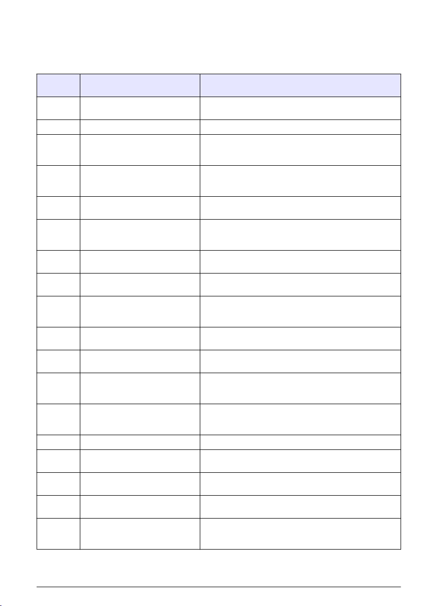
Specification Details
Dimensions (W x D x H) Handheld meters: 9 x 20 x 5 cm (3.5 x 8 x 2 in.)
Weight Handheld meters: 1300 g (3.0 lb.)
Battery enclosure Water resistant
Battery requirements 4-ANSI 15 A or IEC-LR6 (AA Alkaline)
Power consumption Backlight on and Bluetooth™ active: 1 W
Power source Internal power source: 4 AA alkaline or rechargeable nickel metal hydride (NiMH)
Storage temperature –20 to +40 °C (4 to 140 °F)
Operating temperature 5 to 40 °C (41 to 104 °F)
Operating humidity Relative humidity: 50% maximum at 25 ºC (77 ºF), non-condensing
Input connectors Handheld meters: 8-pin ISFET, BNC with phono jack temperature, 12-pin conductivity
USB adapter Peripheral
Data memory (internal) Up to 999 measurement results at user selectable intervals from 1 to 1999 seconds
Data storage Automatic in store mode; user enables data logging mode; data is user stored, recalled
Data export USB connection to PC; transfer the data log or as data is read
Languages English
Temperature correction Off, automatic and manual (parameter dependent)
Measurement Continuous measurement
Protection rating Handheld meters: IP67
Certifications CE
Benchtop meters: 20 x 13 x 8 cm (5 x 8 x 3 in.)
Benchtop meters: 900 g (2.0 lb.)
Backlight on and Bluetooth™ inactive: 50 mW
batteries; battery life: > 200 hours
External power source: 100 to 240 VAC, 50/60 Hz input; 4.5 to 7.0 VDC; 100 mA
(benchtop meters only)
(H170G only)
Benchtop meters: 8-pin ISFET BNC with phono jack temperature, 12-pin conductivity
(H270G only), 2 mm reference, USB and external AC
and deleted
Benchtop meters: IP42
English 3
Page 4
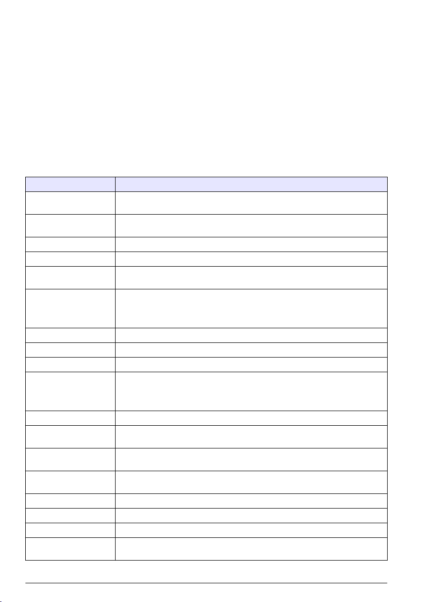
Specification Details
pH
Calibration Up to five points: 1.68, 4.01, 6.86, 7.00, 9.18, 10.01, 12.45
Accuracy ±0.01 pH
Resolution 0.01 pH
Range -2.00 to 19.99
mV
Calibration None
Accuracy ±1 mV
Resolution Autoranging, 0.1 and 1
Range Autoranging, ±199.9 mV to ±1999 mV
Temperature
Calibration None
Accuracy ±0.5 °C
Resolution 0.1 °C (0.1 °F)
Range -5 to 105 °C (23 to 221 °F)
ISE
Calibration Up to five points
Accuracy Probe dependent
Resolution 0.1 ppm–0.1 ppt
Range Autoranging, -0.0 ppm to 1999 ppt
Conductivity
Calibration Up to five points
Accuracy ±1% full scale or ±1 digit
Resolution 0.01 µS, 0.1 µS, 1 µS, 0.01 mS, 0.1 mS
Range Autoranging: 0.00 to 19.99 µS, 20.0 to 199.9 µS, 200 to 1999 µS, 2.00 to 19.99 mS,
TDS
Calibration Up to five points
Accuracy ±1% full scale or ±1 digit
Resolution 0.01 ppm, 0.1 ppm, 1 ppm, 0.01 ppt, 0.1 ppt, 1 ptt, 0.1 mg/L, 1 mg/L, 0.01 gal/L,
Range Autoranging, ppm: 0.00 to 9.99 ppm,10.0 to 99.9 pm,100 to 999 ppm,1.00 to 9.99 ppt,
Salinity
Calibration None (derived from conductivity)
Accuracy ±0.1 ppt (–2 to +35 °C or 28.4 to 95 °F)
Resolution 0.1 ppt, 1%
20.0 to 199.9 mS
0.1 gal/L
10.0 to 99.9 ppt,100 to 200 ppt
mg/L: 0.00 to 199.9 mg/L, 200 to 1999 mg/L, 2.00 to 19.99 gal/L, 20 to 50 gal/L
4 English
Page 5

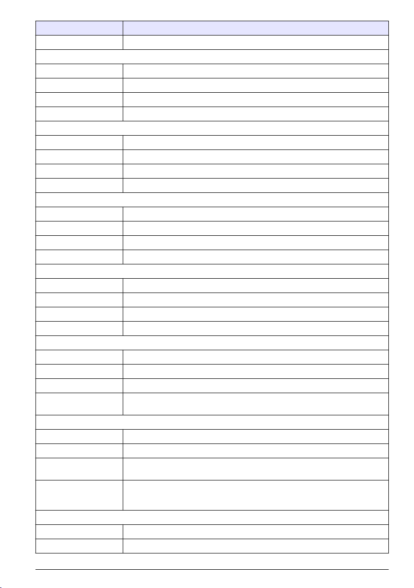
Specification Details
Range 0 to 42, ppt 0 to 4.2%
Dissolved oxygen
Calibration One or two points, user-selectable to any value
Accuracy ±1.5% full scale
Resolution 0.1%, 0.01 ppm or mg/L
Range 0.0% to 199.9% saturation, 0 to 19.99 ppm or mg/L
Barometric pressure
Calibration Factory calibration
Accuracy ±1.5 hPa (10 to 40 °C or 50 to 104 °F)
Resolution 1 mm Hg or 1 hPa 0.01 in Hg±
Range 225 to 900 mm Hg or 300 to 1200 hPa (8.86 to 35.43 in. Hg)
Salinity correction: automatic with conductivity probe
Barometric pressure compensation: automatic
General information
In no event will the manufacturer be liable for direct, indirect, special, incidental or consequential
damages resulting from any defect or omission in this manual. The manufacturer reserves the right to
make changes in this manual and the products it describes at any time, without notice or obligation.
Revised editions are found on the manufacturer’s website.
Safety information
N O T I C E
The manufacturer is not responsible for any damages due to misapplication or misuse of this product including,
without limitation, direct, incidental and consequential damages, and disclaims such damages to the full extent
permitted under applicable law. The user is solely responsible to identify critical application risks and install
appropriate mechanisms to protect processes during a possible equipment malfunction.
Please read this entire manual before unpacking, setting up or operating this equipment. Pay
attention to all danger and caution statements. Failure to do so could result in serious injury to the
operator or damage to the equipment.
Make sure that the protection provided by this equipment is not impaired. Do not use or install this
equipment in any manner other than that specified in this manual.
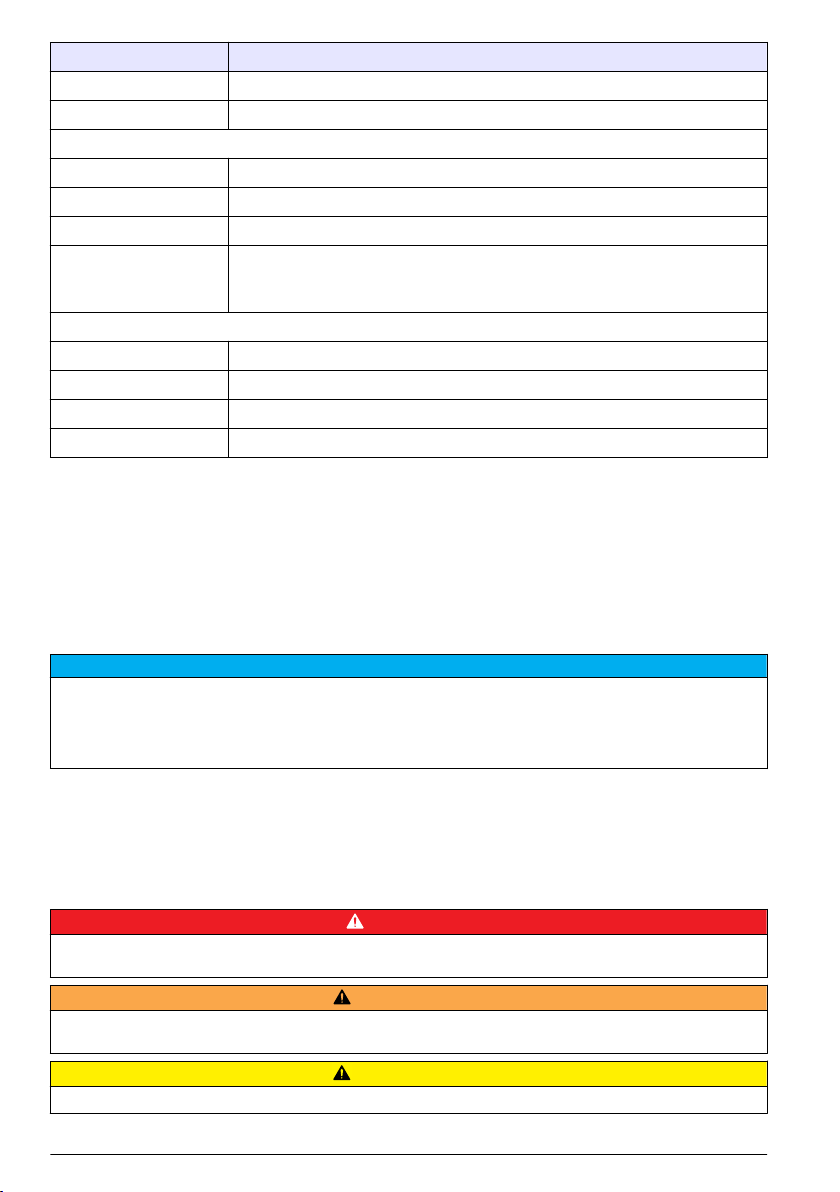
Use of hazard information
Indicates a potentially or imminently hazardous situation which, if not avoided, will result in death or serious injury.
D A N G E R
W A R N I N G
Indicates a potentially or imminently hazardous situation which, if not avoided, could result in death or serious
injury.
Indicates a potentially hazardous situation that may result in minor or moderate injury.
Indicates a situation which, if not avoided, may cause damage to the instrument. Information that requires special
emphasis.
C A U T I O N
N O T I C E
English 5
Page 6
Precautionary labels
Read all labels and tags attached to the instrument. Personal injury or damage to the instrument
could occur if not observed. A symbol on the instrument is referenced in the manual with a
precautionary statement.
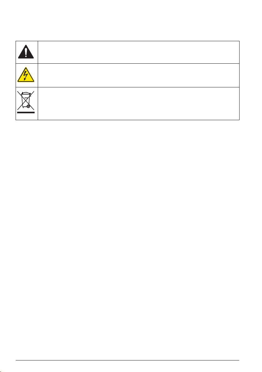
This is the safety alert symbol. Obey all safety messages that follow this symbol to avoid potential
injury. If on the instrument, refer to the instruction manual for operation or safety information.
This symbol indicates that a risk of electrical shock and/or electrocution exists.
Electrical equipment marked with this symbol may not be disposed of in European public disposal
systems after 12 August of 2005. In conformity with European local and national regulations (EU
Directive 2002/96/EC), European electrical equipment users must now return old or end-of-life
equipment to the Producer for disposal at no charge to the user.
Note: For return for recycling, please contact the equipment producer or supplier for instructions on how to return endof-life equipment, producer-supplied electrical accessories, and all auxiliary items for proper disposal.
Certification
Canadian Radio Interference-Causing Equipment Regulation, IECS-003, Class A:
Supporting test records reside with the manufacturer.
This Class A digital apparatus meets all requirements of the Canadian Interference-Causing
Equipment Regulations.
Cet appareil numérique de classe A répond à toutes les exigences de la réglementation canadienne
sur les équipements provoquant des interférences.
FCC Part 15, Class "A" Limits
Supporting test records reside with the manufacturer. The device complies with Part 15 of the FCC
Rules. Operation is subject to the following conditions:
1. The equipment may not cause harmful interference.
2. The equipment must accept any interference received, including interference that may cause
undesired operation.
Changes or modifications to this equipment not expressly approved by the party responsible for
compliance could void the user's authority to operate the equipment. This equipment has been tested
and found to comply with the limits for a Class A digital device, pursuant to Part 15 of the FCC rules.
These limits are designed to provide reasonable protection against harmful interference when the
equipment is operated in a commercial environment. This equipment generates, uses and can
radiate radio frequency energy and, if not installed and used in accordance with the instruction
manual, may cause harmful interference to radio communications. Operation of this equipment in a
residential area is likely to cause harmful interference, in which case the user will be required to
correct the interference at their expense. The following techniques can be used to reduce
interference problems:
1. Disconnect the equipment from its power source to verify that it is or is not the source of the
interference.
2. If the equipment is connected to the same outlet as the device experiencing interference, connect
the equipment to a different outlet.
3. Move the equipment away from the device receiving the interference.
4. Reposition the receiving antenna for the device receiving the interference.
5. Try combinations of the above.
6 English
Page 7

Product overview
N O T I C E
Always disconnect power to the meter when electrodes are changed. Only use the meter as instructed in this
manual or the meter performance can decrease.
The H-series handheld and benchtop meters operate with glass sensor electrodes with BNC
connectors or non-glass probes with ISFET (ion sensitive field effect transistor) silicon chip sensors.
The meters use one pH electrode (a BNC pH electrode or an ISFET pH probe) at a time. When the
meter power is set to on, the meter automatically identifies the type of electrode that is attached.
The H-Series meters are available in eight models:
•
Waterproof handheld meters with Bluetooth™ technology. Refer to Figure 1:
• H160G—pH and ORP
• H170G—pH, ORP, conductivity, TDS and salinity
• Benchtop meters with a USB output. Refer to Figure 2:
• H260G—pH and ORP
• H270G—pH, ORP, conductivity, TDS and salinity
• H280G—pH, ORP, conductivity, TDS, salinity and dissolved oxygen (DO)
• Benchtop meters with Bluetooth™ technology and a USB output. Refer to Figure 2:
• H260GB—pH and ORP
• H270GB—pH, ORP, conductivity, TDS and salinity
• H280GB—pH, ORP, conductivity, TDS, salinity and DO
Note: The difference between the benchtop meters is that the GB benchtop meters have Bluetooth™ technology
and a USB output, and the G benchtop meters only have a USB output. Unless noted, when the benchtop series is
documented in this manual, the benchtop meter includes all of the H-series benchtop meters (both the G and the
GB benchtop meters).
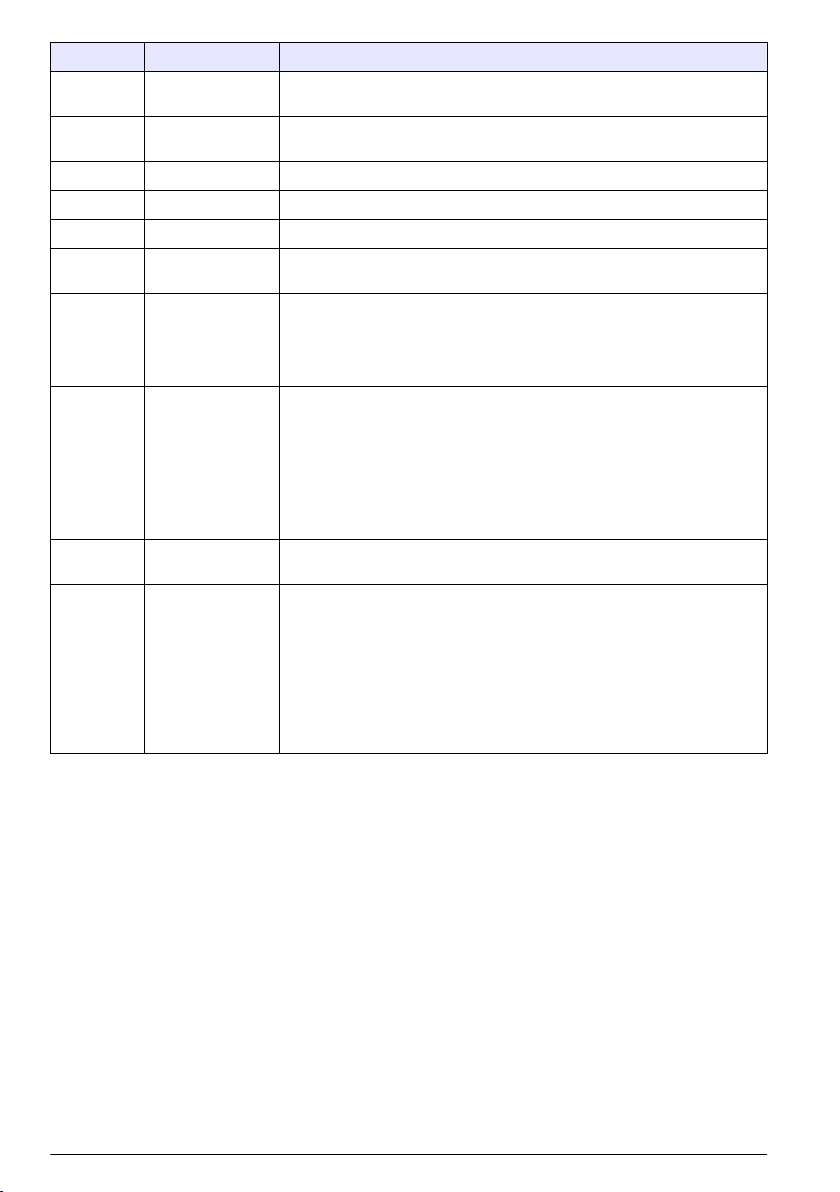
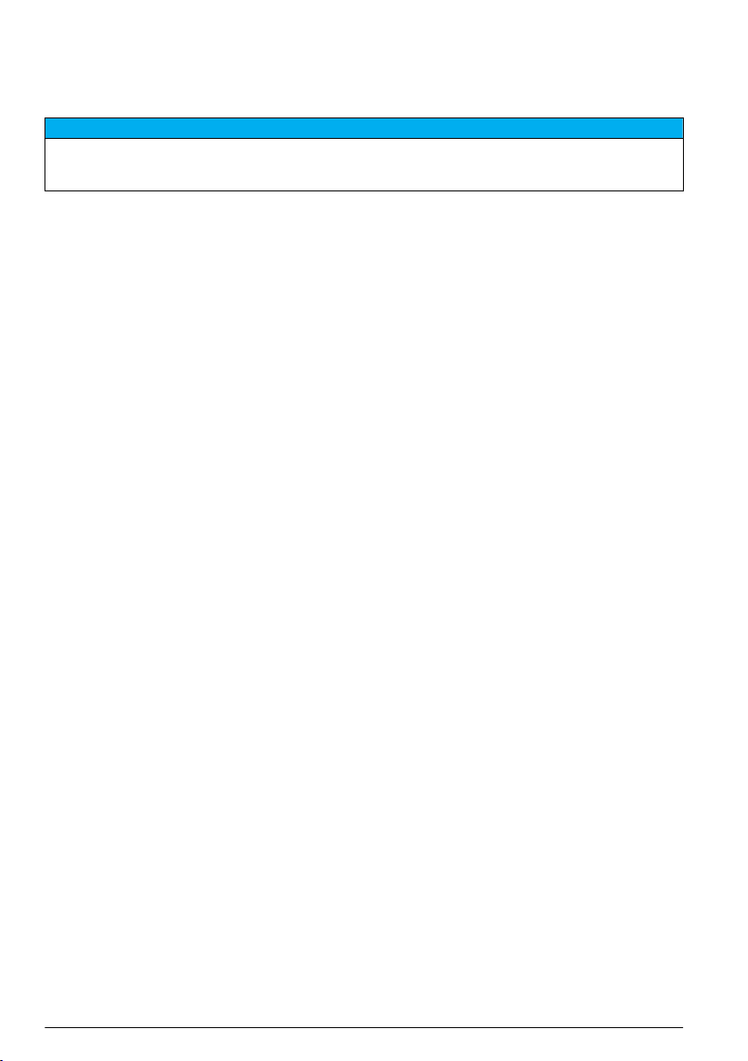
Figure 1 Handheld meter
1 Rubber dust caps 5 ISFET pH probe connector (8-pin)
2 Conductivity probe connection (12-pin, H170G only) 6 LCD display
3 BNC probe connector 7 Power button
4 3.5 mm phono jack for glass pH electrode, ISE,
ORP or DO temperature sensors
8 Battery cover
English 7
Page 8

Figure 2 Benchtop meter
1 Power button 6 ISFET pH probe connector
2 Conductivity probe connector (12-pin, H270G and
H280G only)
3 USB connector 8 External reference connector
4 3.5 phono jack for glass pH electrode, ORP, ISE or
DO temperature sensors
5 BNC connector for glass pH electrode, ISE, ORP or
DO (H280G only) probes
7 AC power connector
9 LCD display
10 Battery cover
Product components
Make sure that all components have been received. Refer to Figure 3. If any items are missing or
damaged, contact the manufacturer or a sales representative immediately.
8 English
Page 9
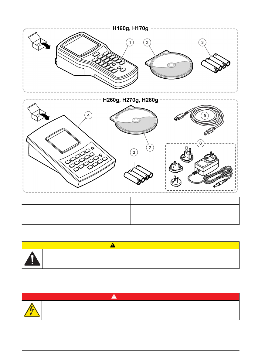
Figure 3 Handheld and benchtop meter components
1 Waterproof handheld meter 4 Benchtop meter
2 SmartLogger II software 5 USB cable
3 AA Alkaline batteries (4x) 6 AC-DC power supply kit (power supply and three
plugs: US, EU, UK)
Installation
C A U T I O N
Multiple hazards. Only qualified personnel must conduct the tasks described in this section of the
document.
Electrical installation
Connect to AC power
D A N G E R
Electrocution hazard. If this equipment is used outdoors or in potentially wet locations, a Ground Fault
Circuit Interrupt (GFCI/GFI) device must be used for connecting the equipment to its main power
source.
English 9
Page 10
W A R N I N G
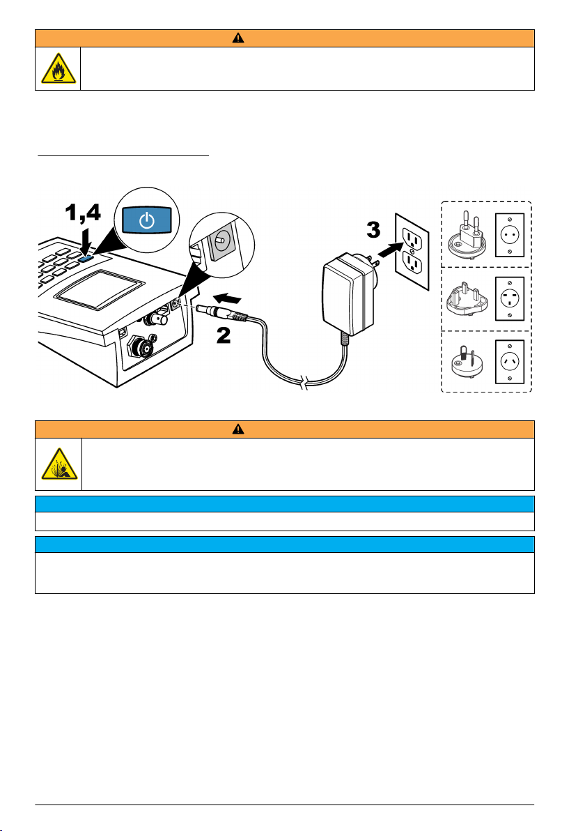
Fire hazard. Use only the power supply that is specified for this instrument.
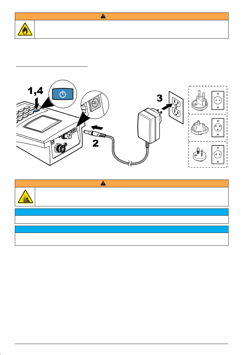
The benchtop meters use AC power with an AC power adapter kit. Refer to Product components
on page
Figure 4 for AC power connections.
Note: Always set power to off before any power connections are made.
8. The kit includes an AC-DC power supply, USB/DC adapter and AC power cord. Refer to
Figure 4 AC power connection
Install the batteries
W A R N I N G
Explosion hazard. Incorrect battery installation can cause the release of explosive gases. Be sure that
the batteries are of the same approved chemical type and are inserted in the correct orientation. Do not
mix new and used batteries.
N O T I C E
Do not tighten the screws too much or instrument damage can occur.
Only do this procedure if the power to the meter is set to off or disconnected. Do not complete this operation with
probes attached to the meter. Remove all probes from the meter or instrument damage can occur.
The meter uses AA alkaline or rechargeable NiMH batteries. To conserve the battery life, refer to
Configure the meter on page 13
Refer to Figure 5 to install the batteries.
Items to collect:
• Phillips screwdriver (for handheld meters)
• Flathead screwdriver (for benchtop meters)
• AA Alkaline batteries (4x)
10 English
to configure automatic shutdown of the meter.
N O T I C E
Page 11

Figure 5 Battery installation
User interface and navigation
Keypad description
Figure 6 shows the handheld and benchtop meter keypads. Table 1 gives the function of the keys on
the keypad and the meters that use that function.
Figure 6 Keypad description
Table 1 Keypad functions
Key Action H160G
H260G
H260GB
ON/OFF: Set the meter power to on or to off. x x x
pH mode x x x
H170G
H270G
H270GB
H280G
H280GB
English 11
Page 12
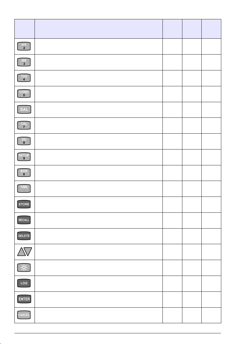
Table 1 Keypad functions (continued)
Key Action H160G
H260G
H260GB
mV mode x x x
ISE mode x x x
TDS mode x x
Conductivity mode x x
Salinity mode x x
Calibration mode x x x
DO mode x
Setup mode x x x
Barometric pressure mode x
H170G
H270G
H270GB
H280G
H280GB
12 English
Time and date display x x x
Store a reading x x x
Recall a stored reading. x x x
Delete a stored reading. x x x
Scroll through values, setup screens and options. x x x
Set the backlight to on. After 2 minutes without a keystroke, the
backlight is set to off.
Start/stop the data log x x x
Select an option, setting or value. x x x
Cancel an option, setting or value. x x x
x x x
Page 13
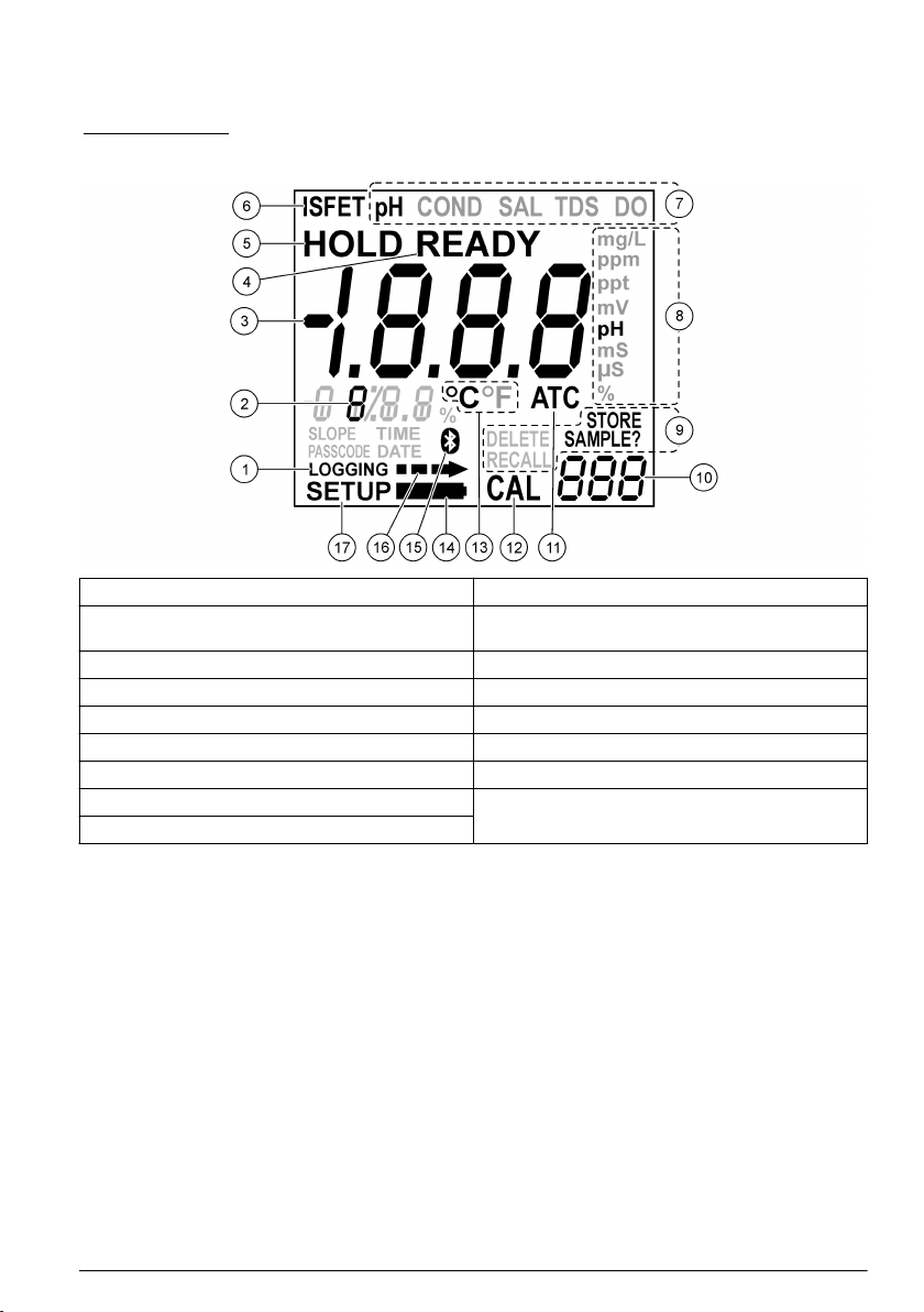
Display description
Figure 7 shows the measurement modes and values, data connection and storage options, battery
status, temperature values, stabilization lock and connection statuses shown on the display.
Figure 7 Display
1 Data log indicator 10 Data storage memory location
2 Temperature and data values 11 Automatic temperature compensation (ATC) value
3 Measured value 12 Calibration mode indicator
4 Stabilization lock 13 Temperature unit
5 Hold indicator 14 Low battery indicator
6 ISFET probe indicator 15 Bluetooth™ connection indicator
7 Measurement mode 16 PC data transfer icon
8 Measurement units 17 Setup mode
9 Storage options
(pH, conductivity, TDS or salinity)
Startup
Set the power to on
Push the power button to set the power to on or off. Make sure that the power supply (AC power or
battery power) is correctly installed.
Configure the meter
Do the operations in order:
1. Set the power to on.
2. Push SETUP to put the meter in setup mode.
3. Use the arrow keys to select an option, then push ENTER:
English 13
Page 14
Option Function Description
CLr ALL
CAL
int Data log interval Keeps up to 999 data points in intervals from 1 to 1999 seconds (default =
year Year Use the number keys to enter the correct year.
date Date format Sets the date to mm/dd/yy or dd/mm/yy format.
m/d date Month and day Use the number keys to set the correct month and day.
time Time Sets the correct time in a 24-hour format. Use the number keys to set the
oFF Automatic
Snd Sound options Sets sound alerts to on or off. Three sounds tell the user about different
Clear calibration
points
shutdown
Erases all the calibration points. Make sure to calibrate the meter.
10) in the data log.
correct time.
Sets the shutdown parameters from 1 minute to 000 minutes (continuous
power). The meter beeps 1 minute before shutdown. Make sure to power
cycle for the automatic shutdown to occur. Automatic shutdown is disabled
during: data logging, Bluetooth™ transfers and when connected to the USB
port.
functions:
• One beep: Stabilization occurred with the stabilization lock on.
• Two beeps: An error occurred. The error code shows on the display.
Refer to Troubleshooting on page 17.
• Three beeps: Measurement stability in calibration mode, regardless of
the stabilization lock setting.
1
ºC ºF Temperature
READY Stabilization lock Sets the stabilization lock to on or off:
1
This does not erase calibration data for an ISFET probe.
display
Sets the temperature unit from ºC to ºF.
• The "READY" icon shows when an endpoint occurs and the stabilization
lock is set to on.
• After stabilization, the display locks the value and the meter ignores slight
measurement changes in pH, conductivity or TDS.
• Sets the stabilization lock to off during titrations or slight change
detection. The display automatically unlocks after a significant
measurement change is found.
4. Push ENTER to keep the changes and go back to setup mode.
Note: To exit and not keep the changes, push CANCEL.
Operation
Configure the Bluetooth™
Transfer data and control several instrument functions from a remote location to a PC with the
Bluetooth™ wireless connection.
Note: The arrow icon shows on the display when the meter is in communication with the SmartLogger II software
on a PC. The arrow icon flashes when data is transferred. Refer to the SmartLogger II documentation to setup the
wireless connection to a PC.
1. Set the power to on. The meter looks for the Bluetooth™ connection with a PC.
2. On the PC, select the option to find or add a Bluetooth™ device. Next, the PC prompts if the user
wants to pair with a found device.
3. When the PC prompts for a pass key or PIN, enter the PIN (default = 1234). The PC shows if the
pair is successful and the meter shows the Bluetooth™ icon.
wireless connection
14 English
Page 15
4. If the pair is not successful, do steps 1 through 4
Note: If there is more than one meter in range, each meter is identified with the model number and the serial
number (e.g., H170G LP SN1 2755).
again.
Send data to a PC
Transmit data in storage to a PC and see real-time measurement values from a remote location on a
PC. Refer to the SmartLogger II PC software guide for operation instructions for the PC to USB
connection.
1. Set the power to off.
2. Connect the USB cable to the USB port of the PC.
3. Use the USB drivers to make a USB connection to the PC.
4. Set the power to on. Refer to the SmartLogger II documentation for data transfer information.
Maintenance
Replace the batteries
The display shows "bAt" when the batteries are too low to give a reliable measurement. The low
battery icon (refer to Display description on page 13) shows when there is approximately 25 hours of
battery power. Measurement errors are possible when the batteries are low. Refer to Install the
batteries on page 10 to replace the batteries.
Note: The date and time must be set again when the batteries are removed or are fully discharged.
Clean the instrument
Clean the exterior of the instrument with a moist cloth and a mild soap solution and then wipe the
instrument dry.
ISFET pH probe maintenance
C A U T I O N
Multiple hazards. Only qualified personnel must conduct the tasks described in this section of the
document.
C A U T I O N
Chemical exposure hazard. Obey laboratory safety procedures and wear all of the personal protective
equipment appropriate to the chemicals that are handled. Refer to the current safety data sheets
(MSDS/SDS) for safety protocols.
The expected life of an ISFET probe is approximately 18 months. The reference electrode has a KCI
gel that is diluted over time. The reference is sealed and is non-refillable. Replace the probe when it
becomes difficult to calibrate.
Keep the probe dry with the protective shroud on when not in use.
•
• Clean oil, fat, food particles, starch, protein or other materials from the probe tip after use.
• Never use sharp metal objects (e.g., a needle, a pin, etc.) to clean the sensor surface.
• Remove the probe from environments with static electricity. Electrostatic discharge (ESD) can
permanently damage the probe.
• Remove the probe from environments that will damage the sensor, such as hydrofluoric acid or
abrasive samples.
English 15
Page 16

• Remove the probe from environments that will damage the epoxy materials used in the probe tip
(e.g., keep the probe away from acetone, toluene, methylene chloride, xylene and other strong
organic solvents).
•
Do not use the probe in temperatures more than 60 ºC (140 ºF). Thermal cycling can decrease the
life of the probe.
• For semi-solids use, carefully twist the probe to make sufficient contact with the sample to the
sensor.
• When semi-solids are tested, make sure that solid objects (i.e., bone or gristle) do not scratch the
sensor.
• Cool samples to room temperature to maximize probe life.
• Always use new buffers and new rinse solutions.
Prepare the probe for storage
N O T I C E
Do not use the probe for long-term pH measurement applications.
Note: No electrode storage solution is necessary.
A new probe usually has visible reference gel at the tip of the probe, as well as in the interior of the
rubber dust cap. To remove the gel, carefully clean with a soft-bristled toothbrush and mild soapy
water (a few drops of dish soap in a warm cup of water). The gel can continue to show for two to five
days. Do not put the rubber dust cap on the probe until all of the reference gel is removed. Do not
complete the steps that follow until all reference gel is removed from the probe and the interior and
exterior of the rubber dust cap.
Prepare the probe for storage
1. Put the new probe (or the probe that was in extended storage) in pH 7 buffer for at least
5 minutes.
2. Stir the probe in pH 7 buffer solution to dislodge air bubbles.
3. Use fresh deionized water to rinse the probe.
4. Dry the probe with a lint-free cloth.
5. Put the rubber dust cap back on.
6. Keep the probe in dry storage when not in use.
Calibrate the ISFET probe
Refer to Prepare the probe for storage on page 16 before calibration.
N O T I C E
Do not use the probe for applications that cycle between hot and room temperature samples.
Note: Remove other active or non-active measurement devices during pH or conductivity measurement. Other
devices, even AC power, can cause interference.
Note: Only do calibrations away from the sun. Direct sunlight can cause unstable readings or difficulty in
calibration.
1. Connect the probe to the meter.
2. Set the meter power to on.
3. Clean the probe with new deionized water and dry with a lint-free cloth.
4. Put the probe in the pH 7 buffer.
5. Clean the probe with deionized water and dry with a lint-free cloth.
6. Put the probe in the second buffer (pH 4 or pH 10).
7. Read the results.
8. If the result is not correct, the probe is not correctly hydrated.
Soak the probe for another 5 minutes in pH 7 buffer, then do the calibration again.
16 English
Page 17
Clean the ISFET probe
N O T I C E
Do not use sharp metal objects (a needle, a pin, etc.) to clean the sensor. This can scratch the sensor and cause
permanent damage to the probe.
For use in dairy, cheese or meat applications, soak the probe in Pepsin Cleaning Solution for
15 minutes before the probe is cleaned.
Regularly clean a non-glass probe:
1. Remove the rubber dust cap from the probe, then rinse with new deionized water.
2. Use a soft-bristle toothbrush and a mild detergent (a few drops of dish soap in a warm cup of
water) to carefully clean the probe.
3. Rinse with new deionized water to remove all debris from the sensor surface.
4. Dry the probe with a lint-free cloth.
5. Calibrate the probe again. Refer to Calibrate the ISFET probe on page
probe for storage on page 16.
16, then Prepare the
Repair the ISFET probes
N O T I C E
Do not use the probe to find out if the buffer is above 60 °C (140 °F). If the probe is suddenly put into very hot
liquid, the probe can be permanently damaged.
Monitor how long the probes are in dry storage. If the probes are in storage for an extended period of
time, the KCI gel at the reference junction can crystallize.
1. Heat pH 7 buffer to approximately 45 to 60 °C (115 to 140 °F).
2. Soak the probe for 2 minutes.
3. Put the probe in room temperature pH 7.00 buffer and let cool.
BNC electrode maintenance
Prevent unstable readings:
•
Keep the probe in an electrode storage solution.
• Start measurements with at least a 2-point calibration. Update often with 1, 2 or 3-point
calibrations.
• Use new buffers and new deionized rinse solution.
• Use buffer solutions with pH values no larger than 3 pH units apart. Ideally, the buffers bracket the
anticipated pH values of the unmeasured samples.
• Use deionized water to rinse residual buffer and sample solutions from the probe after calibration
and measurement.
• Calibrate at the same temperature as the sample solution. Although the meter has an ATC, get the
best results when the calibration buffers and the sample are the same temperature.
• Keep the connectors clean and dry. Dirty or damp connectors can cause unstable readings.
Troubleshooting
Problem Possible cause Solution
No display Automatic shutdown set the
power to off.
There is no power. Replace the batteries.
Set the power to on again.
English 17
Page 18
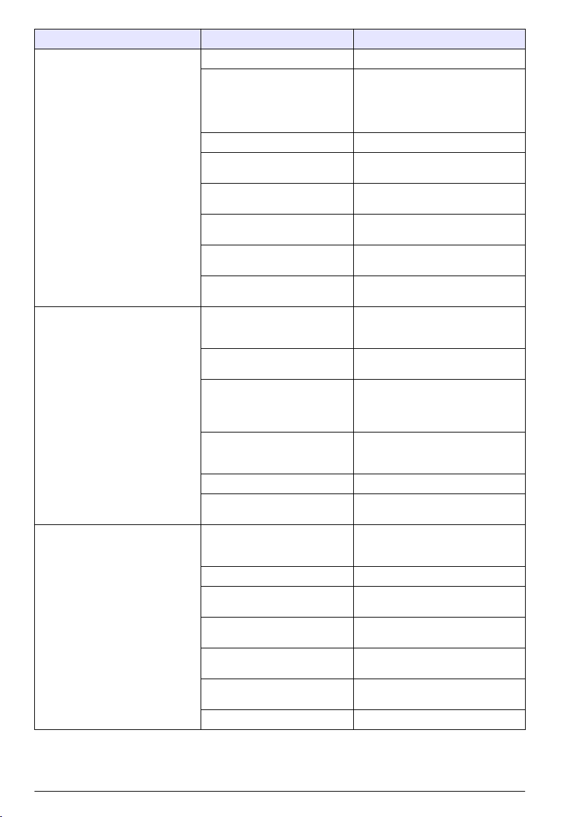
Problem Possible cause Solution
Unstable reading The probe is dirty. Clean the probe.
The probe or the meter
connectors are dirty.
No flow in the reference junction Clean the warm buffer.
ISFET probe is not correctly
hydrated.
Interference from other devices Remove other devices from the
Interference from direct sunlight Use protection for the probe from
The probe is in a very low ionic
strength solution.
The pH or temperature of the
solution changes.
The meter continually
shows –2.00 or 19.99 with an
electrode attached. The "ISFET" icon
does not show when ISFET probe is
attached.
Screen flashes during calibration. The probe sensor surfaces are
The ISFET probe is not sensed
by the meter or the probe.
Out of calibration Calibrate the ISFET probe
The probe is not in the solution. Put the probe in liquid. Carefully
No probe is connected to the
meter.
The probe is dirty. Clean the probe.
The probe is damaged. Replace the probe. Contact technical
dirty or it is necessary for the
probe to be conditioned again.
No flow in the reference junction Clean the warm buffer.
The buffers are contaminated or
expired.
Interference from other devices in
the solution
The battery is low. Replace the batteries if the battery
Interference from direct sunlight Use protection for the probe from
The probe is too old. Replace the probe.
Clean the probe contacts on the cable
connector. Clean the meter with
methanol on a cotton swab. Let dry
completely. Connect the probe to the
meter again.
Soak the probe for at least 5 minutes
in a pH 7.00 buffer.
solution.
direct sunlight.
A stable reading is not possible.
A stable reading is not possible until
pH and temperature are constant.
Set the meter power to off. If the
"ISFET" icon does not show, replace
the ISFET probe.
on page 16.
shake the probe to make sure that air
bubbles are not caught on the sensor
surface.
Set the meter power to off. Connect
the pH probe. Set the meter power to
on.
support.
Clean and condition the probe again.
Calibrate with new buffers again.
Remove all devices from the solution.
icon shows low battery power.
direct sunlight.
18 English
Page 19
Error codes
Table 2 shows the codes that can occur for various reasons. Error codes show instrument
malfunction or user error.
Table 2 Error code descriptions
Error
Code
E02 The ISFET pH probe is damaged. Replace the probe. Contact technical support for probe
E03 Clean the probe. Clean the probe. If the error continues, replace the probe.
E04 Glass pH probe slope error. The
E06 ISFET pH probe slope error. Clean the probe. Soak in 40 ºC (113 ºF) pH 7.00 buffer for
E07 Clean the probe. Clean the probe. Make sure that no air bubbles on the sensor
E08 Too long to calibrate. Signal is not
E13 The ISFET pH probe temperature
E14 The battery is extremely low. Replace the batteries immediately. Damage to the accuracy
E15 Replace the battery immediately.
E20 The conductivity temperature
E25 The slope is smaller than 60% or
E26 The mV reading is more than
E27 DO probe temperature error Attach the temperature sensor to the 3.5 mm phono jack. DO
E28 Barometric pressure sensor error Contact technical support for repair information.
E30 ISE electrode calibration error The slopes are not the same sign or are not within 25% of
E40 Unrecognized host command Command from a host PC is not found. Use only valid
E42 Invalid input The value entered during the setup is invalid. Enter a
E44 No probe is installed No probe is installed for the applicable parameter. Set the
Description Solution
replacement information.
slope is smaller than 85% or larger
than 102% of 59.16 mV per pH unit.
stable during calibration.
sensor is damaged.
The accuracy and function of the
meter could be compromised.
sensor is damaged.
larger than 140% of the nominal.
±10 mV from nominal.
Clean the probe. If the error continues, replace the probe.
2 minutes. Calibrate again. If the error continues, replace the
probe.
surface or foreign objects or materials on the sensor.
Clean the probe. Disconnect stirrers and other AC power
sources. Make sure that the calibration solution temperature
is constant. Replace the probe if the error continues.
Replace the probe. Contact technical support for probe
replacement information.
and function of the meter could have occurred.
Contact technical support for service information.
Replace the probe. Contact technical support for probe
replacement information.
Replace DO probe membrane and fill solution. Replace the
probe if the error continues. Nominal = 0.1822 ppm/mV.
Replace DO probe membrane and fill solution. Replace the
probe if the error continues. Nominal = 0.0 mV at 0%
saturation; 45mV at 100%.
readings are highly temperature dependent and a
temperature sensor must be attached.
each other. Calibrate again in the correct solutions.
commands.
different value.
meter power to off. Install the correct probe. Set the meter
power to on.
English 19
Page 20
Inhaltsverzeichnis
Zusätzliche Informationen auf Seite 20
Technische Daten auf Seite 20
Allgemeine Informationen auf Seite 22
Installation auf Seite 27
Benutzeroberfläche und Navigation auf Seite 29
Inbetriebnahme auf Seite 32
Betrieb auf Seite 33
Wartung auf Seite 34
Fehlerbehebung auf Seite 37
Zusätzliche Informationen
Zusätzliche Informationen finden Sie auf der Website des Herstellers.
Technische Daten
Änderungen vorbehalten.
Technische Daten Details
Abmessungen (B x T x H) Tragbare Messgeräte: 9 x 20 x 5 cm
Gewicht Tragbare Messgeräte: 1.300 g
Batteriegehäuse Wasserabweisend
Batterieanforderungen 4 ANSI 15 A oder IEC-LR6 (AA Alkali)
Leistungsaufnahme Hintergrundbeleuchtung eingeschaltet und Bluetooth™ aktiv: 1 W
Stromquelle Interne Stromquelle: 4 AA-Alkali oder aufladbare Nickelmetallhydrid-Akkus (NiMH);
Lagertemperatur -20 bis +40 °C (4 bis 140 °F)
Betriebstemperatur 5 bis 40 °C (41 bis 104 °F)
Luftfeuchtigkeit bei Betrieb Relative Luftfeuchtigkeit: maximal 50 % bei 25 ºC (77 ºF), nicht kondensierend
Eingangsanschlüsse Tragbare Messgeräte: ISFET 8-polig, Temperatur BNC mit Klinkenbuchse,
USB-Adapter Peripher
Datenspeicher (intern) Bis zu 999 Messergebnisse in vom Benutzer wählbaren Intervallen von 1 bis
Datenspeicher Im Speichermodus automatisch; Benutzer aktiviert den·Datenspeichermodus; Daten
Datenexport USB-Verbindung zu PC; Übertragung des Datenspeichers oder direkt bei
Sprachen Englisch
Temperaturkorrektur Aus, automatisch und manuell (parameterabhängig)
Messung Kontinuierliche Messung
Schutzart Tragbare Messgeräte: IP67
Tischmessgerät: 20 x 13 x 8 cm
Tischmessgeräte: 900 g.)
Hintergrundbeleuchtung eingeschaltet und Bluetooth™ inaktiv: 50 mW
Lebensdauer des Akkus: > 200 Stunden
Externe Stromquelle: 100 bis 240 VAC, 50/60 Hz Eingang; 4,5 bis 7,0 VDC; 100 mA
(nur Tischmessgeräte)
Leitfähigkeit 12-polig (nur H170G)
Tischmessgeräte: ISFET 8-polig, Temperatur BNC mit Klinkenbuchse, Leitfähigkeit
12-polig (nur H170G), 2 mm Referenz, USB und externes Netzteil
1.999 Sekunden
werden vom Benutzer gespeichert, abgerufen und gelöscht
Datenerfassung
Tischmessgeräte: IP42
20 Deutsch
Page 21
Technische Daten Details
Zertifizierungen CE
pH
Kalibrierung Bis zu fünf Punkte: 1,68, 4,01, 6,86, 7,00, 9,18, 10,01, 12,45
Genauigkeit ±0,01 pH
Auflösung 0,01 pH
Messbereich -2,00 bis 19,99
mV
Kalibrierung Keine
Genauigkeit ±1 mV
Auflösung Autoranging: 0,1 und 1
Messbereich Autoranging: ± 199,9 mV bis ± 1999 mV
Temperatur
Kalibrierung Keine
Genauigkeit ±0.5 °C
Auflösung 0.1 °C (0.1 °F)
Messbereich -5 bis 105 °C (23 bis 221 °F)
ISE
Kalibrierung Bis zu fünf Punkte
Genauigkeit Sondenabhängig
Auflösung 0,1 ppm bis 0,1 ppt
Messbereich Autoranging: -0,0 ppm bis 1999 ppt
Leitfähigkeit
Kalibrierung Bis zu fünf Punkte
Genauigkeit ±1 % Endausschlag oder ±1 Stelle
Auflösung 0,01 µS, 0,1 µS, 1 µS, 0,01 mS, 0,1 mS
Messbereich Autoranging: 0,00 bis·19,99 µS, 20,0 bis·199,9 µS, 200 bis·1999 µS,
TDS
Kalibrierung Bis zu fünf Punkte
Genauigkeit ±1 % Endausschlag oder ±1 Stelle
Auflösung 0,01 ppm, 0,1 ppm, 1 ppm, 0,01 ppt, ,1 ppt, 1 ppt, 0,1 mg/l, 1 mg/l, 0,01 gal/l,
Messbereich Autoranging, ppm: 0,00 bis·9,99 ppm,10,0 bis·99,9 ppm, 100 bis·999 ppm,
Salinität
Kalibrierung Keine·(von der Leitfähigkeit abgeleitet)
Genauigkeit ±0,1 ppt (–2 bis·+35 °C oder 28,4 bis·95 °F)
2,00 bis·19,99 mS, 20,0 bis·199,9 mS
0,1 gal/l
1,00 bis·9,99 ppt, 10,0 bis·99,9 ppt, 100 bis·200 ppt
mg/l: 0,00 bis·199,9 mg/l, 200 bis·1999 mg/l, 2,00 bis·19,99 gal/l, 20 bis·50 gal/l
Deutsch 21
Page 22
Technische Daten Details
Auflösung 0,1 ppt, 1 %
Messbereich 0 bis·42, ppt 0 bis·4,2 %
Gelöster Sauerstoff
Kalibrierung Ein oder zwei Punkte, jeder Wert kann vom Benutzer gewählt werden
Genauigkeit ±1.5 % Endausschlag
Auflösung 0,1 %, 0,01 ppm oder mg/l
Messbereich 0,0 % bis 199,9 % Sättigung, 0 bis 19,99 ppm oder mg/l
Luftdruck
Kalibrierung Werkseitige Kalibrierung
Genauigkeit ±1,5 hPa (10 bis 40 °C oder 50 bis 104 °F)
Auflösung 1 mm Hg oder 1 hPa 0,01 in Hg±
Messbereich 225 bis 900 mm Hg oder 300 bis 1200 hPa (8,86 bis 35,43 in. Hg)
Salinitätskorrektur: automatisch mit Leitfähigkeitssonde
Luftdruckkompensation: automatisch
Allgemeine Informationen
Der Hersteller ist nicht verantwortlich für direkte, indirekte, versehentliche oder Folgeschäden, die
aus Fehlern oder Unterlassungen in diesem Handbuch entstanden. Der Hersteller behält sich
jederzeit und ohne vorherige Ankündigung oder Verpflichtung das Recht auf Verbesserungen an
diesem Handbuch und den hierin beschriebenen Produkten vor. Überarbeitete Ausgaben der
Bedienungsanleitung sind auf der Hersteller-Webseite erhältlich.
Sicherheitshinweise
H I N W E I S
Der Hersteller ist nicht für Schäden verantwortlich, die durch Fehlanwendung oder Missbrauch dieses Produkts
entstehen, einschließlich, aber ohne Beschränkung auf direkte, zufällige oder Folgeschäden, und lehnt jegliche
Haftung im gesetzlich zulässigen Umfang ab. Der Benutzer ist selbst dafür verantwortlich, schwerwiegende
Anwendungsrisiken zu erkennen und erforderliche Maßnahmen durchzuführen, um die Prozesse im Fall von
möglichen Gerätefehlern zu schützen.
Bitte lesen Sie dieses Handbuch komplett durch, bevor Sie dieses Gerät auspacken, aufstellen oder
bedienen. Beachten Sie alle Gefahren- und Warnhinweise. Nichtbeachtung kann zu schweren
Verletzungen des Bedieners oder Schäden am Gerät führen.
Stellen Sie sicher, dass die durch dieses Messgerät bereitgestellte Sicherheit nicht beeinträchtigt
wird. Verwenden bzw. installieren Sie das Messsystem nur wie in diesem Handbuch beschrieben.
Bedeutung von Gefahrenhinweisen
Kennzeichnet eine mögliche oder drohende Gefahrensituation, die, wenn sie nicht vermieden wird, zum Tod oder
zu schweren Verletzungen führt.
G E F A H R
W A R N U N G
Kennzeichnet eine mögliche oder drohende Gefahrensituation, die, wenn sie nicht vermieden wird, zum Tod oder
zu schweren Verletzungen führen kann.
Kennzeichnet eine mögliche Gefahrensituation, die zu geringeren oder moderaten Verletzungen führen kann.
V O R S I C H T
22 Deutsch
Page 23
H I N W E I S
Kennzeichnet eine Situation, die, wenn sie nicht vermieden wird, das Gerät beschädigen kann. Informationen, die
besonders beachtet werden müssen.
Warnhinweise
Lesen Sie alle am Gerät angebrachten Aufkleber und Hinweise. Nichtbeachtung kann Verletzungen
oder Beschädigungen des Geräts zur Folge haben. Im Handbuch wird in Form von Warnhinweisen
auf die am Gerät angebrachten Symbole verwiesen.
Dies ist das Sicherheits-Warnsymbol. Befolgen Sie alle Sicherheitshinweise im Zusammenhang mit
diesem Symbol, um Verletzungen zu vermeiden. Wenn es am Gerät angebracht ist, beachten Sie die
Betriebs- oder Sicherheitsinformationen im Handbuch.
Dieses Symbol weist auf die Gefahr eines elektrischen Schlages hin, der tödlich sein kann.
Elektrogeräte, die mit diesem Symbol gekennzeichnet sind, dürfen ab 12. August 2005 nicht in
öffentlichen europäischen Abfallsystemen entsorgt werden. Benutzer von Elektrogeräten müssen in
Europa in Einklang mit lokalen und nationalen europäischen Regelungen (EU-Richtlinie 2002/96/EG)
Altgeräte kostenfrei dem Hersteller zur Entsorgung zurückgeben.
Hinweis: Mit der Wiederverwertung, der stofflichen Verwertung oder anderen Formen der Verwertung von Altgeräten
leisten Sie einen wichtigen Beitrag zum Schutz unserer Umwelt.
Zertifizierung
Kanadische Vorschriften zu Störungen verursachenden Einrichtungen, IECS-003, Klasse A:
Entsprechende Prüfprotokolle hält der Hersteller bereit.
Dieses digitale Gerät der Klasse A erfüllt alle Vorgaben der kanadischen Normen für Interferenz
verursachende Geräte.
Cet appareil numérique de classe A répond à toutes les exigences de la réglementation canadienne
sur les équipements provoquant des interférences.
FCC Teil 15, Beschränkungen der Klasse "A"
Entsprechende Prüfprotokolle hält der Hersteller bereit. Das Gerät entspricht Teil 15 der FCCVorschriften. Der Betrieb unterliegt den folgenden Bedingungen:
1. Das Gerät darf keine Störungen verursachen.
2. Das Gerät muss jegliche Störung, die es erhält, einschließlich jener Störungen, die zu
unerwünschtem Betrieb führen, annehmen.
Änderungen oder Modifizierungen an diesem Gerät, die nicht ausdrücklich durch die für die
Einhaltung der Standards verantwortliche Stelle bestätigt wurden, können zur Aufhebung der
Nutzungsberechtigung für dieses Gerät führen. Dieses Gerät wurde geprüft, und es wurde
festgestellt, dass es die Grenzwerte für digitale Geräte der Klasse A entsprechend Teil 15 der FCCVorschriften einhält. Diese Grenzwerte sollen einen angemessenen Schutz gegen
gesundheitsschädliche Störungen gewährleisten, wenn dieses Gerät in einer gewerblichen
Umgebung betrieben wird. Dieses Gerät erzeugt und nutzt hochfrequente Energie und kann diese
auch abstrahlen, und es kann, wenn es nicht in Übereinstimmung mit der Bedienungsanleitung
installiert und eingesetzt wird, schädliche Störungen der Funkkommunikation verursachen. Der
Betrieb dieses Geräts in Wohngebieten kann schädliche Störungen verursachen. In diesem Fall
muss der Benutzer die Störungen auf eigene Kosten beseitigen. Probleme mit Interferenzen lassen
sich durch folgende Methoden mindern:
1. Trennen Sie das Gerät von der Stromversorgung, um sicherzugehen, dass dieser die Störungen
nicht selbst verursacht.
2. Wenn das Gerät an die gleiche Steckdose angeschlossen ist wie das gestörte Gerät, schließen
Sie das störende Gerät an eine andere Steckdose an.
3. Vergrößern Sie den Abstand zwischen diesem Gerät und dem gestörten Gerät.
Deutsch 23
Page 24
4. Ändern Sie die Position der Empfangsantenne des gestörten Geräts.
5. Versuchen Sie auch, die beschriebenen Maßnahmen miteinander zu kombinieren.
Produktübersicht
H I N W E I S
Trennen Sie stets die Stromversorgung zum Messgerät, wenn Sie Elektroden austauschen. Verwenden Sie das
Messgerät ausschließlich entsprechend den Anweisungen in diesem Handbuch, da sonst dessen Leistung
beeinträchtigt werden kann.
Die tragbaren Geräte·und Tischmessgeräte der Serie H funktionieren mit Glassensorelektroden mit
BNC-Anschlüssen oder Sonden ohne Glas mit ISFET-Siliziumchipsensoren (ISFET = ionenselektiver
Feldeffekttransistor). In den Messgeräten·wird jeweils eine pH-Elektrode verwendet (eine BNC-pHElektrode oder eine ISFET-pH-Sonde). Wird das Messgerät eingeschaltet, wird der Typ der
angeschlossenen Elektrode automatisch identifiziert.
Die Messgeräte der Serie H sind in acht Modellen erhältlich:
•
Wasserdichte tragbare Messgeräte mit Bluetooth™-Technologie. Siehe Abbildung 1:
• H160G – pH und ORP
• H170G – pH, ORP, Leitfähigkeit, TDS und Salinität
• Tischmessgeräte mit einem USB-Ausgang. Siehe Abbildung 2:
• H260GB – pH und ORP
• H270G – pH, ORP, Leitfähigkeit, TDS und Salinität
• H280G – pH, ORP, Leitfähigkeit, TDS, Salinität·und gelöster Sauerstoff (DO)
• Tischmessgeräte mit Bluetooth™-Technologie und einem USB-Ausgang. Siehe Abbildung 2:
• H260GB – pH und ORP
• H270GB – pH, ORP, Leitfähigkeit, TDS und Salinität
• H280GB – pH, ORP, Leitfähigkeit, TDS, Salinität·und DO
Hinweis: Der Unterschied der Tischmessgeräte besteht darin, dass die GB-Tischmessgeräte über Bluetooth™-
Technologie und einen USB-Anschluss verfügen und die G-Tischmessgeräte lediglich über einen USB-Ausgang.
Sofern nicht anders angegeben, gelten die Angaben in diesem Handbuch für alle Tischmessgeräte der Serie H
(sowohl für die G-Modelle als auch für die GB-Modelle).
24 Deutsch
Page 25
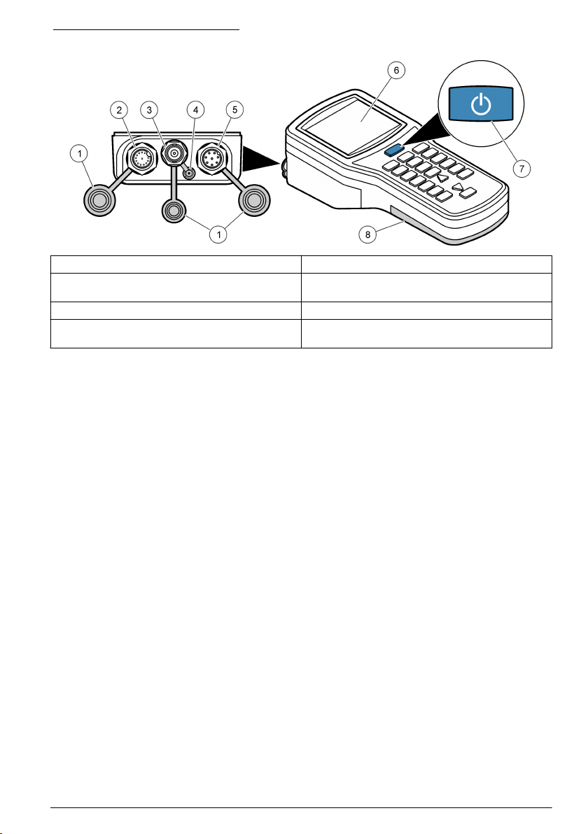
Abbildung 1 Tragbares Messgerät
1 Staubschutzkappen aus Gummi 5 Anschluss für·ISFET-pH-Sonde (8-polig)
2 Anschluss für Leitfähigkeitssonde (12-polig, nur
H170G)
3 Anschluss für BNC-Sonde 7 Ein/Aus-Schalter
4 3,5-mm-Klinkenbuchse für pH-Elektrode aus Glas,
ISE, ORP oder DO-Temperatursensoren
6 LCD-Display
8 Batteriefachabdeckung
Deutsch 25
Page 26
Abbildung 2 Tischmessgerät
1 Ein/Aus-Schalter 6 Anschluss für·ISFET-pH-Sonde
2 Anschluss für Leitfähigkeitssonde (12-polig, nur
H270G und H280G)
3 USB-Anschluss 8 Anschluss für externe Referenz
4 3,5 mm-Klinkenbuchse für pH-Elektrode aus Glas,
ISE-, ORP- oder DO-Temperatursensoren
5 BNC-Anschluss für pH-Elektrode aus Glas, ISE-,
ORP-·oder DO-Sonden (letztere nur für H280G)
7 Netzstecker
9 LCD-Display
10 Batteriefachabdeckung
Produktkomponenten
Stellen Sie sicher, dass Sie alle Teile erhalten haben. Siehe Abbildung 3. Wenn Komponenten fehlen
oder beschädigt sind, kontaktieren Sie bitte den Hersteller oder Verkäufer.
26 Deutsch
Page 27
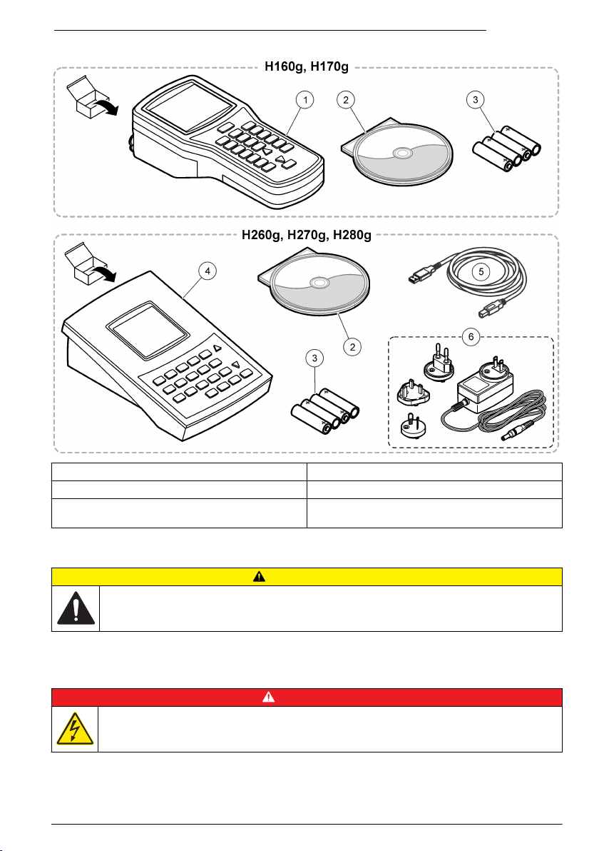
Abbildung 3 Komponenten eines tragbaren Geräts·und eines Tischmessgeräts
1 Wasserdichtes tragbares Messgerät 4 Tischmessgerät
2 SmartLogger II-Software 5 USB-Kabel
3 Alkali-Batterien Größe AA (4x) 6 AC/DC Stromversorgungskit (Stromversorgung und
drei Stecker: US, EU, GB)
Installation
V O R S I C H T
Mehrere Gefahren. Nur qualifiziertes Personal sollte die in diesem Kapitel des Dokuments
beschriebenen Aufgaben durchführen.
Elektrische Installation
Anschluss an den Netzstrom
G E F A H R
Lebensgefahr durch Stromschlag. Wenn dieses Gerät im Freien oder an potenziell feuchten Standorten
eingesetzt wird, muss eine Fehlerstrom-Schutzeinrichtung zum Anschluss an die Netzversorgung
verwendet werden.
Deutsch 27
Page 28
W A R N U N G
Brandgefahr. Verwenden Sie nur die für dieses Gerät spezifizierte Stromversorgung.
Die Tischmessgeräte funktionieren mithilfe eines Netzstromadapters mit Netzstrom. Siehe
Produktkomponenten auf Seite 26
. Dieses Kit enthält ein AC-/DC-Netzteil, einen USB/DC-Adapter
und ein Netzkabel. Informationen zum Anschließen an den Netzstrom finden Sie unter·Abbildung 4.
Hinweis: Schalten·Sie das Gerät stets aus, bevor Sie·Stromanschlüsse vornehmen.
Abbildung 4 AC-Netzanschluss
Einlegen der Batterien
W A R N U N G
Explosionsgefahr. Das unsachgemäße Einlegen von Batterien kann zur Freisetzung explosiver Gase
führen. Vergewissern Sie sich, dass Sie Batterien mit dem zulässigen Chemikalientyp verwenden und
dass sie mit der korrekten Polung eingelegt wurden. Verwenden Sie nicht alte und neue Batterien
zusammen.
Ziehen Sie die Schrauben nicht zu fest an, da dies zu Schäden am Gerät führen kann.
Führen Sie dieses Verfahren nur durch, wenn das Messgerät ausgeschaltet oder von der Stromversorgung
getrennt ist. Führen Sie diesen Vorgang nicht aus, wenn Sonden an das Messgerät angeschlossen sind.
Entfernen Sie alle Sonden vom Messgerät,·da sonst das Gerät beschädigt werden kann.
Das Messgerät wird·mit AA-Alkalibatterien oder NiMH-Akkus betrieben. Die Lebensdauer der
Batterien verlängert werden, indem das automatische Abschalten des Messgerät konfiguriert wird;
siehe Konfigurieren des Messgeräts auf Seite 32.
Informationen zum Einlegen der Batterien finden Sie in Abbildung 5.
Zusätzlich erforderliche Gegenstände:
•
Kreuzschlitzschraubendreher (für tragbare Geräte)
• Schlitzschraubendreher (für Tischmessgeräte)
• Alkali-Batterien Größe AA (4x)
H I N W E I S
H I N W E I S
28 Deutsch
Page 29
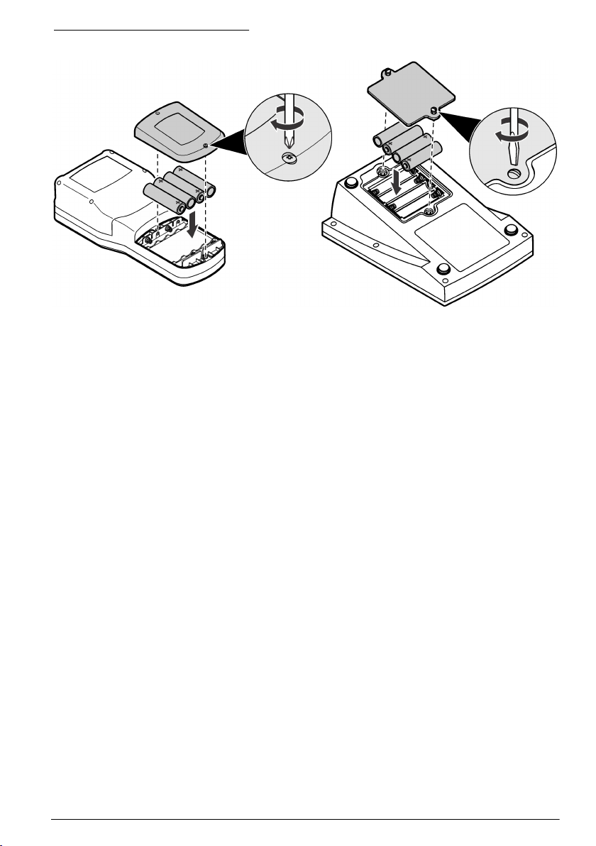
Abbildung 5 Einlegen der Batterien
Benutzeroberfläche und Navigation
Beschreibung des Tastenfelds
In Abbildung 6
sind die Funktionen der Tasten auf dem Tastenfeld und den Geräten angegeben, die diese
Funktionen verwenden.
sind die Tastenfelder für tragbare Geräte und Tischgeräte dargestellt. In Tabelle 1
Deutsch 29
Page 30
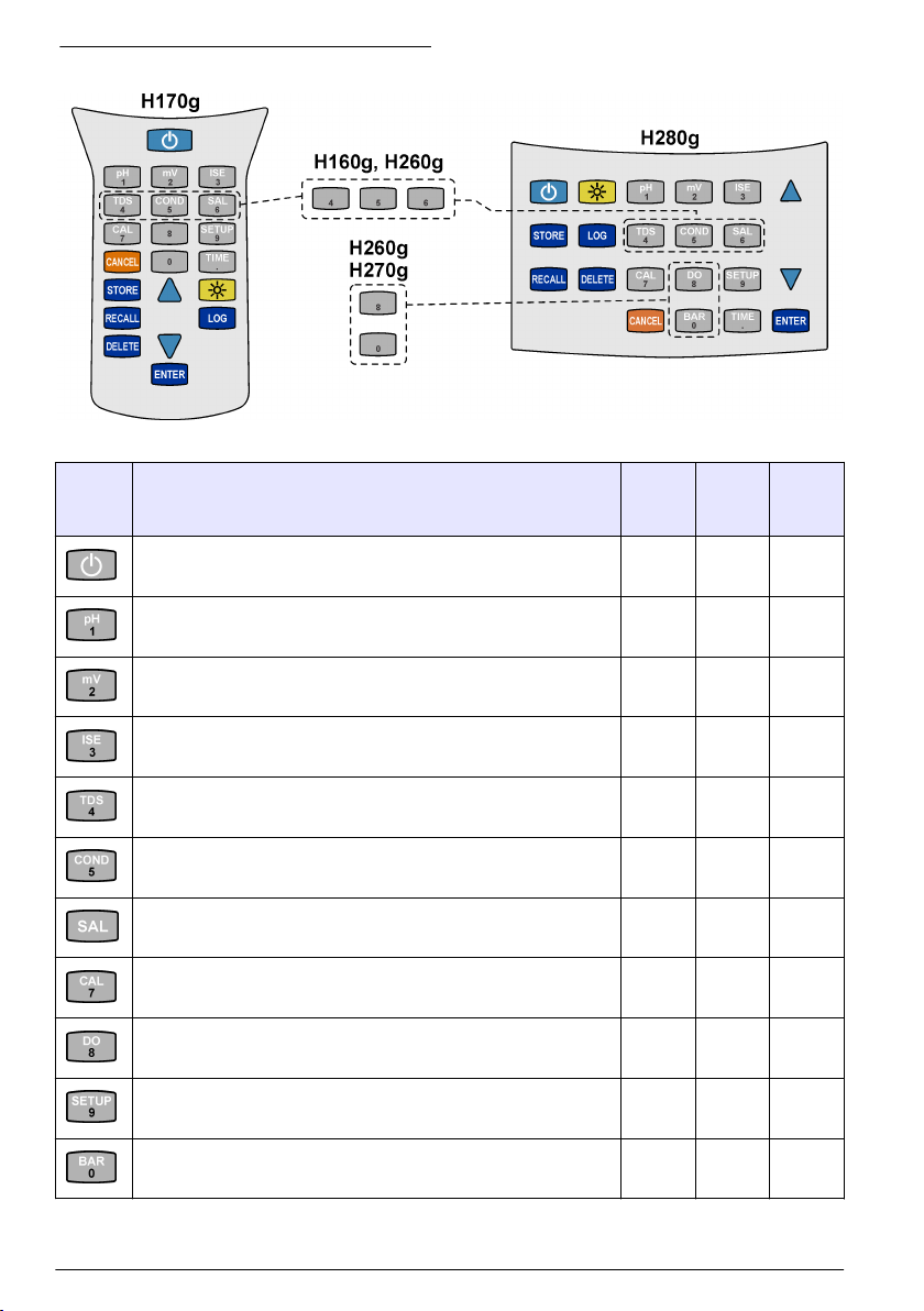
Abbildung 6 Beschreibung des Tastenfelds
Tabelle 1 Tastenfeld-Funktionen
Taste Aktion H160G
H260G
H260GB
ON/OFF: Zum Ein- und Ausschalten des Messgeräts. x x x
pH-Modus x x x
mV-Modus x x x
H170G
H270G
H270GB
H280G
H280GB
30 Deutsch
ISE-Modus x x x
TDS-Modus x x
Leitfähigkeitsmodus x x
Salinitätsmodus x x
Kalibriermodus x x x
DO-Modus x
Setup-Modus x x x
Luftdruckmodus x
Page 31

Tabelle 1 Tastenfeld-Funktionen (fortgesetzt)
Taste Aktion H160G
H260G
H260GB
Anzeige von Uhrzeit und Datum x x x
Speichern eines Messwerts x x x
Abrufen eines gespeicherten Messwerts x x x
Löschen·eines gespeicherten Messwerts x x x
Navigieren durch Werte, Setup-Bildschirme und Optionen x x x
H170G
H270G
H270GB
H280G
H280GB
Einschalten der Hintergrundbeleuchtung Nach 2 Minuten ohne
Tastenbedienung wird die Hintergrundbeleuchtung ausgeschaltet.
Starten/Stoppen der Datenspeicherung x x x
Auswählen einer Option, einer Einstellung oder eines Wertes x x x
Abbrechen·einer Option, einer Einstellung oder eines Wertes x x x
x x x
Displaybeschreibung
In Abbildung 7
Batteriestatus, die Temperaturwerte, die Stabilisierungssperre und der Verbindungsstatus
dargestellt, die im Display angezeigt werden.
sind die Messmodi und -werte, die Datenverbindungs- und Speicheroptionen, der
Deutsch 31
Page 32

Abbildung 7 Display
1 Datenspeicheranzeige 10 Datenspeicherort
2 Temperatur- und Datenwerte 11 Wert der automatischen Temperaturkompensation
3 Gemessener Wert 12 Anzeige für den Kalibriermodus
4 Stabilisierungssperre 13 Temperatureinheit
5 Halteanzeige 14 Anzeige für·schwache Batterie
6 Anzeige für ISFET-Sonde 15 Anzeige für Bluetooth™-Verbindung
7 Messmodus 16 Symbol für Datenübertragung mit PC
8 Maßeinheiten 17 Setup-Modus
9 Speicheroptionen
(ATC) (pH-Wert, Leitfähigkeit, TDS oder Salinität)
Inbetriebnahme
Einschalten
Drücken Sie die Einschalttaste, um das Messgerät ein- oder auszuschalten. Vergewissern Sie sich,
dass die Stromversorgung (Netzstrom oder Batteriebetrieb) korrekt installiert ist.
Konfigurieren des Messgeräts
Gehen Sie in der folgenden Reihenfolge vor:
1. Schalten Sie das Gerät ein.
2. Drücken Sie SETUP, um das Messgerät in den·Setup-Modus zu versetzen.
3. Wählen Sie mit den Pfeiltasten eine Option aus, und drücken Sie dann ENTER:
Optionen Funktion Beschreibung
CLr ALL CAL Kalibrierpunkte löschen Löscht alle Kalibrierpunkte. Achten Sie darauf, das Messgerät zu
Int Intervall für
Datenspeicherung
year Jahr Geben·Sie mit den·Zifferntasten das richtige Jahr ein.
kalibrieren.
Speichert·bis zu 999 Datenpunkte in Intervallen·von 1 bis
1999 Sekunden (Standard = 10) im Datenspeicher.
32 Deutsch
1
Page 33

Optionen Funktion Beschreibung
date Datumsformat Zum Einstellen des Datums im Format MM/TT/JJ oder TT/MM/JJ.
m/d date Monat und Tag Geben·Sie mit den Zifferntasten den richtigen Monat und den Tag
time Uhrzeit Zum Einstellen der richtigen Uhrzeit im 24-Stunden-Format.
oFF Ausschaltautomatik Zum Einstellen der Abschaltparameter von 1 Minute auf 000 Minuten
Snd Signaltöne Zum Ein- und Ausschalten von Signaltönen. Die Töne informieren
ºC ºF Temperaturanzeige Zum Festlegen der Temperatureinheit als °C oder °F.
READY Stabilisierungssperre Zum Ein- und Ausschalten der Stabilisierungssperre:
ein.
Geben·Sie mit den·Zifferntasten die·richtige Uhrzeit·ein.
(kontinuierlicher Betrieb). Das Messgerät piept eine Minute vor dem
Abschalten. Führen Sie einen Neustart durch, damit das
automatische Abschalten durchgeführt werden kann. Das
automatische Abschalten ist während der Datenaufzeichnung,
Bluetooth™-Übertragungen und bei Verbindung mit dem USBAnschluss deaktiviert.
den Benutzer über unterschiedliche Funktionen:
• Ein Piepton: Stabilisierung trat bei eingeschalteter
Stabilisierungssperre auf.
• Zwei Pieptöne: Es ist ein Fehler aufgetreten. Der·Fehlercode wird
im Display angezeigt. Siehe Fehlerbehebung auf Seite 37.
• Drei Pieptöne: Messungsstabilität im Kalibriermodus, unabhängig
von der Einstellung der Stabilisierungssperre.
• Das Symbol „READY“ wird angezeigt, wenn ein Endpunkt auftritt
und die Stabilisierungssperre aktiviert ist.
• Nach der Stabilisierung wird der Wert vom Display gesperrt, und
leichte Messwertänderungen in pH, Leitfähigkeit oder TDS werden
vom Messgerät ignoriert.
• Schaltet·die Stabilisierungssperre während Titrationen oder der
Erkennung von leichten Änderungen aus. Das·Display·wird
automatisch entsperrt, nachdem signifikante Messwertänderungen
erkannt wurden.
1
Dadurch·werden keine Kalibrierungsdaten für eine ISFET-Sonde gelöscht.
4. Drücken Sie ENTER, um die Änderungen zu speichern·und zum Setup-Modus zurückzukehren.
Hinweis: Drücken Sie CANCEL, um abzubrechen und die Änderungen nicht zu übernehmen.
Betrieb
Konfigurieren der Bluetooth™-Wireless-Verbindung
Übertragen von Daten und Steuern·mehrerer Gerätefunktionen von einem entfernten Standort an
einen PC mit der Bluetooth™-Wireless-Verbindung.
Hinweis: Mit dem Pfeilsymbol im Display wird angezeigt, wenn das Messgerät Daten mit der SmartLogger IISoftware auf einem PC austauscht. Das·Pfeilsymbol blinkt, wenn Daten übertragen werden. Informationen zur
Einrichtung der drahtlosen Verbindung zu einem PC entnehmen Sie der SmartLogger II-Dokumentation.
1. Schalten Sie das Gerät ein. Vom Messgerät wird nach einer·Bluetooth™-Verbindung mit einem
PC gesucht.
2. Wählen Sie am·PC die Option zum Suchen oder Hinzufügen·eines Bluetooth™-Geräts aus. Als
Nächstes wird der Benutzer vom PC gefragt, ob Kontakt mit einem gefundenen Gerät hergestellt
werden soll.
Deutsch 33
Page 34

3. Wenn Sie vom PC zur Eingabe eines Pass-Keys oder einer PIN aufgefordert werden, geben Sie
die PIN (Standard = 1234) ein. Auf dem PC wird angezeigt, ob die Verbindung erfolgreich
hergestellt werden konnte,·und auf dem Messgerät wird das·Bluetooth™-Symbol angezeigt.
4. Wenn die Verbindung nicht erfolgreich hergestellt werden konnte, wiederholen·Sie die Schritte 1
bis 4.
Hinweis: Falls sich mehrere Geräte im Erfassungsbereich befinden, wird jedes Gerät mit der Modellnummer
und der Seriennummer (z. B. H170G LP SN1 2755) identifiziert.
Senden von Daten an einen PC
Sie können Daten aus dem Speicher an einen PC senden und Messwerte von einem entfernten
Standort in Echtzeit auf einem PC ansehen. Anweisungen zum Herstellen einer PC-zu-USBVerbindung entnehmen Sie der SmartLogger II-PC-Softwareanleitung.
1. Schalten Sie das Gerät aus.
2. Verbinden Sie das USB-Kabel mit dem USB-Anschluss am PC.
3. Stellen Sie mithilfe der USB-Treiber eine USB-Verbindung zum PC her.
4. Schalten Sie das Gerät ein. Informationen zur Datenübertragung finden Sie in der Dokumentation
zu SmartLogger II.
Wartung
Auswechseln der Batterien
Im Display wird „bAt“ angezeigt, wenn die Batterien für eine zuverlässige Messung zu schwach sind.
Das Batteriesymbol (siehe Displaybeschreibung
25 Stunden Batterieleistung vorhanden ist. Wenn die Batterien zu schwach sind, können Messfehler
auftreten. Informationen zum Auswechseln der Batterien finden Sie unter Einlegen der Batterien
auf Seite 28.
Hinweis: Datum und Uhrzeit müssen neu eingestellt werden, wenn die Batterien herausgenommen werden oder
komplett entladen sind.
auf Seite 31) wird angezeigt, wenn für noch etwa
Wartung der ISFET-pH-Sonde
V O R S I C H T
Mehrere Gefahren. Nur qualifiziertes Personal sollte die in diesem Kapitel des Dokuments
beschriebenen Aufgaben durchführen.
V O R S I C H T
Gefahr von Kontakt mit Chemikalien. Halten Sie sich an die Sicherheitsmaßnahmen im Labor, und
tragen Sie Schutzkleidung entsprechend den Chemikalien, mit denen Sie arbeiten. Beachten Sie die
Sicherheitsprotokolle in den aktuellen Materialsicherheitsdatenblättern (MSDS/SDB).
Die Lebensdauer einer ISFET-Sonde beträgt ca. 18 Monate. Die Referenzelektrode verfügt über ein
KCI-Gel, das im Laufe der Zeit verdünnt wird. Die Referenz ist versiegelt und kann nicht aufgefüllt
werden. Ersetzen Sie die Sonde, wenn ihre Kalibrierung kompliziert wird.
Halten Sie die Sonde trocken, und bringen Sie bei Nichtverwendung die Schutzabdeckung an.
•
• Entfernen Sie nach der Verwendung Öl, Fette, Lebensmittelreste, Stärke, Proteine und andere
Materialien von der Sondenspitze.
• Verwenden Sie niemals scharfe Objekte (z. B. Nadeln, Stifte usw.), um die Sensoroberfläche zu
reinigen.
34 Deutsch
Page 35

• Entfernen Sie die Sonde aus Umgebungen mit statischer Elektrizität. Elektrostatische Entladungen
können die Sonde dauerhaft beschädigen.
•
Entfernen Sie die Sonde aus Umgebungen, die den Sensor beschädigen, z. B.
Fluorwasserstoffsäure oder abrasive Proben.
• Entfernen Sie die Sonde aus Umgebungen, die die Harzbestandteile in der Sondenspitze
beschädigen können (halten Sie die Sonde fern von z. B. Azeton, Toluol, Methylenchlorid, Xylol
und anderen starken organischen Lösungsmitteln).
• Verwenden Sie die Sonde nicht in Temperaturen über 60 ºC (140 ºF). Wechselnde Temperaturen
können die Lebensdauer der Sonde verkürzen.
• Drehen Sie die Sonde bei Verwendung in halbfesten Stoffen, damit ausreichend Probe mit dem
Sensor in Kontakt kommt.
• Vergewissern Sie sich beim Testen von halbfesten Stoffen, dass feste Objekte (z. B. Knochen
oder Knorpel) den Sensor nicht zerkratzen.
• Kühlen Sie Proben auf Zimmertemperatur ab, um ihre Lebensdauer zu maximieren.
• Verwenden Sie immer neue Puffer und neue Spüllösungen.
Vorbereiten der Sonde auf die Lagerung
H I N W E I S
Verwenden Sie die Sonde nicht für Langzeit-pH-Messungen.
Hinweis: Es ist keine Elektrodenaufbewahrungslösung erforderlich.
Eine neue Sonde weist normalerweise sichtbares Referenzgel an der Spitze sowie im inneren der
Gummistaubkappe auf. Zum Entfernen des Gels reinigen Sie die Sonde vorsichtig mit einer weichen
Zahnbürste und mildem Seifenwasser (einige Tropfen Geschirrspülmittel in einer Tasse mit warmem
Wasser). Unter Umständen bleibt das Gel noch zwei bis fünf Tage sichtbar. Stecken Sie die
Gummistaubkappe erst auf die Sonde, wenn kein Referenzgel mehr vorhanden ist. Führen Sie die
nachfolgenden Schritte erst aus, wenn sich kein Referenzgel mehr an der Sonde sowie innen und
außen an der Gummistaubkappe befindet.
Vorbereiten der Sonde auf die Lagerung
1. Legen Sie die neue Sonde (oder eine lange Zeit gelagerte Sonde) mindestens 5 Minuten lang in
Puffer mit einem pH-Wert von 7.
2. Rühren Sie mit der Sonde in der pH-7-Pufferlösung, um Luftblasen zu beseitigen.
3. Verwenden Sie zum Spülen der Sonde frisches entionisiertes Wasser.
4. Trocknen Sie die Sonde mit einem fusselfreien Tuch.
5. Setzen Sie die Gummistaubkappe wieder auf.
6. Lagern Sie die Sonde trocken, wenn sie nicht verwendet wird.
Kalibrieren der ISFET-Sonde
Lesen Sie vor der Kalibrierung Vorbereiten der Sonde auf die Lagerung auf Seite 35.
H I N W E I S
Verwenden Sie die Sonde nicht für Anwendungen, bei denen sich heiße Proben und Proben mit
Zimmertemperatur abwechseln.
Hinweis: Entfernen Sie andere aktive und inaktive Messgeräte während der pH- oder Leitfähigkeitsmessung.
Andere Geräte, selbst Netzspannung, können zu Interferenzen führen.
Hinweis: Führen Sie Kalibrierungen stets ohne Sonneneinstrahlung durch. Direkte Sonneneinstrahlung kann zu
instabilen Messergebnissen oder Schwierigkeiten bei der Kalibrierung führen.
1. Schließen Sie die Sonde an das Messgerät an.
2. Schalten Sie das Messgerät ein.
3. Reinigen Sie die Sonde mit frischem entionisiertem Wasser, und trocknen Sie sie mit einem
fusselfreien Tuch.
4. Legen Sie die Sonde in den pH 7 Puffer.
Deutsch 35
Page 36

5. Reinigen Sie die Sonde mit entionisiertem Wasser, und trocknen Sie sie mit einem fusselfreien
Tuch.
6. Legen Sie die Sonde in den zweiten Puffer (pH 4 oder pH 10).
7. Messen Sie die Werte.
8. Wenn das Ergebnis nicht korrekt ist, dann ist die Sonde nicht korrekt hydriert.
Legen Sie die Sonde weitere 5 Minuten in pH 7 Puffer, und führen Sie die Kalibrierung dann
erneut aus.
Reinigen der ISFET-Sonde
H I N W E I S
Verwenden Sie keine scharfen Metallobjekte (Nadeln, Stifte usw.), um den Sensor zu reinigen. Andernfalls wird
der Sensor zerkratzt, was zu permanenten Schäden an der Sonde führt.
Wenn die Sonde bei Milch-, Käse- oder Fleischanwendungen eingesetzt wird, legen Sie sie
15 Minuten lang in Pepsin Cleaning Solution, bevor die Sonde gereinigt wird.
Regelmäßige Reinigung einer glasfreien Sonde:
1. Entfernen Sie die Gummistaubkappe von der Sonde, und spülen Sie sie dann mit frischem
entionisiertem Wasser.
2. Reinigen Sie die Sonde vorsichtig mit einer Zahnbürste mit weichen Borsten und einem milden
Reinigungsmittel (einige Tropfen Geschirrspülmittel in einer Tasse mit warmem Wasser).
3. Spülen Sie mit frischem entionisiertem Wasser, um alle Ablagerungen von der Sensoroberfläche
zu entfernen.
4. Trocknen Sie die Sonde mit einem fusselfreien Tuch.
5. Kalibrieren Sie die Sonde erneut. Siehe Kalibrieren der ISFET-Sonde auf Seite 35, dann
Vorbereiten der Sonde auf die Lagerung auf Seite 35.
Reparieren der ISFET-Sonden
H I N W E I S
Verwenden Sie die Sonde nicht, um herauszufinden, ob der Puffer wärmer als 60 °C (140 °F) ist. Wenn die
Sonde plötzlich mit sehr heißer Flüssigkeit in Kontakt kommt, kann die Sonde permanent beschädigt werden.
Überwachen Sie, wie lange die Sonden trocken gelagert werden. Wenn die Sonden über einen
langen Zeitraum trocken gelagert werden, kann das KCI-Gel an der Referenzverbindung
kristallisieren.
1. Erwärmen Sie pH-7-Puffer auf etwa 45 bis 60 °C (115 bis 140 °F).
2. Weichen Sie die Sonde 2 Minuten lang ein.
3. Legen Sie die Sonde in einen Puffer bei Zimmertemperatur mit pH 7,00, und lassen Sie sie
abkühlen.
Wartung der BNC-Elektrode
Instabile Messergebnisse vermeiden:
•
Lagern Sie die Sonde in einer Aufbewahrungslösung für Elektroden.
• Beginnen Sie Messungen mindestens mit einer 2-Punkt-Kalibrierung. Aktualisieren Sie häufig mit
1-, 2- oder 3-Punkt-Kalibrierungen.
• Verwenden Sie neue Puffer und neue entionisierte Spüllösung.
• Verwenden Sie Pufferlösungen mit pH-Werten, die nicht mehr als 3 pH-Einheiten auseinander
liegen. Im Idealfall umschließen die Puffer die erwarteten pH-Werte der nicht gemessenen Proben.
• Spülen Sie Restpuffer und Probenlösungen nach der Kalibrierung und Messung mit entionisiertem
Wasser von der Sonde ab.
• Kalibrieren Sie bei der Temperatur, die der Probenlösung entspricht. Obwohl das Messgerät über
ATC verfügt, lassen sich die besten Ergebnisse erzielen, wenn die Kalibrierungspuffer und die
Probe dieselbe Temperatur haben.
36 Deutsch
Page 37

• Halten Sie die Anschlüsse sauber und trocken. Verschmutzte oder feuchte Anschlüsse können zu
instabilen Messergebnissen führen.
Fehlerbehebung
Problem Mögliche Ursache Lösung
Keine Anzeige Das Gerät wurde durch die
Messung nicht stabil Die Sonde ist verschmutzt. Reinigen Sie die Sonde.
Das Messgerät zeigt
kontinuierlich -2,00 oder
19,99 an, wenn eine Elektrode
angeschlossen ist. Das „ISFET“Symbol wird nicht angezeigt,
wenn die ISFET-Sonde
angeschlossen ist.
automatische Abschaltung
ausgeschaltet.
Keine Stromversorgung Wechseln Sie die Batterien aus.
Die Sonde oder die
Messgerätanschlüsse sind
verschmutzt.
Kein Durchfluss in der
Vergleichsstelle
ISFET-Sonde nicht richtig
hydratisiert.
Störungen von anderen Geräten Entfernen Sie die anderen Geräte
Störungen durch direkte
Sonneneinstrahlung
Die Sonde befindet sich·in einer
Lösung mit sehr niedriger
Ionenstärke.
Der pH-Wert oder die Temperatur
der Lösung schwankt.
Die·ISFET-Sonde wird nicht
vom·Messgerät oder von der
Sonde erfasst.
Außerhalb der Kalibrierung Kalibrieren der ISFET-Sonde
Die Sonde befindet sich nicht·in
der Lösung.
Es ist keine Sonde mit dem
Messgerät verbunden.
Die Sonde ist verschmutzt. Reinigen Sie die Sonde.
Die Sonde ist beschädigt. Ersetzen Sie die Sonde. Wenden Sie
Schalten Sie das Gerät wieder ein.
Reinigen Sie die Sondenkontakte am
Kabelanschluss. Reinigen Sie das
Messgerät mit einem Wattestäbchen
und Methanol. Lassen Sie es
vollständig trocknen. Schließen Sie die
Sonde wieder an das Messgerät an.
Reinigen Sie den Wärmepuffer.
Legen Sie die Sonde mindestens
5 Minuten lang in einen Puffer mit dem
pH-Wert 7,00.
aus·der Lösung.
Schützen Sie die Sonde vor direkter
Sonneneinstrahlung.
Eine stabile Messung ist nicht möglich.
Eine stabile Messung·ist erst möglich,
wenn der pH-Wert und die Temperatur
konstant sind.
Schalten Sie das Messgerät aus. Wenn
das·„ISFET“-Symbol nicht angezeigt
wird, ersetzen Sie die ISFET-Sonde.
auf Seite 35.
Geben Sie die Sonde in die Flüssigkeit.
Schütteln Sie die Sonde vorsichtig, um
sicherzustellen, dass sich keine
Luftblasen an der Sensoroberfläche
befinden.
Schalten Sie das Messgerät aus.
Schließen·Sie die pH-Sonde an.
Schalten Sie das Messgerät ein.
sich an den technischen
Kundenservice.
Deutsch 37
Page 38

Problem Mögliche Ursache Lösung
Der Bildschirm blinkt während der
Kalibrierung.
Die Sondenoberflächen des
Sensors sind verschmutzt, oder
die Sonde muss erneut
konditioniert werden.
Kein Durchfluss in der
Vergleichsstelle
Die Puffer sind verunreinigt oder
abgelaufen.
Störungen von anderen Geräten in
der Lösung
Die Batterie ist zu schwach. Ersetzen Sie die Batterien, wenn das
Störungen durch direkte
Sonneneinstrahlung
Die Sonde ist zu alt. Ersetzen Sie die Sonde.
Reinigen und konditionieren Sie die
Sonde erneut.
Reinigen Sie den Wärmepuffer.
Kalibrieren Sie noch einmal mit neuen
Puffern.
Entfernen Sie alle·Geräte aus·der
Lösung.
Batteriesymbol eine schwache
Batterieleistung anzeigt.
Schützen Sie die Sonde vor direkter
Sonneneinstrahlung.
Fehlercodes
In Tabelle 2 sind die Codes aufgeführt, die aus verschiedenen Gründen angezeigt werden können.
Mit Fehlercodes werden Gerätestörungen oder Bedienfehler angezeigt.
Tabelle 2 Fehlercodebeschreibungen
Fehlercode Beschreibung Lösung
E02 Die·ISFET pH-Sonde ist beschädigt. Ersetzen Sie die Sonde. Wenden Sie sich an den
E03 Sonde reinigen Reinigen Sie die Sonde. Falls der Fehler weiterhin
E04 Steilheitsfehler der pH-Sonde mit Glas
Die Steilheit ist kleiner als 85 % oder
größer als 102 % von 59,16 mV pro pHEinheit.
E06 Steilheitsfehler der ISFET pH-Sonde Reinigen Sie die Sonde. 2 Minuten lang in 40 ºC
E07 Sonde reinigen Reinigen Sie die Sonde. Achten Sie darauf, dass sich
E08 Kalibrierung dauert zu lang. Das Signal ist
während der Kalibrierung nicht stabil.
E13 Der Temperatursensor der ISFET pH-
Sonde ist beschädigt.
E14 Die Batterie ist sehr schwach. Ersetzen Sie die Batterien umgehend. Möglicherweise
technischen Support, um Informationen für den
Sondenaustausch zu erhalten.
auftritt, ersetzen Sie die Sonde.
Reinigen Sie die Sonde. Falls der Fehler weiterhin
auftritt, ersetzen Sie die Sonde.
(113 ºF) warmen Puffer mit pH-Wert 7,00 legen.
Führen Sie die Kalibrierung erneut durch. Falls der
Fehler weiterhin auftritt, ersetzen Sie die Sonde.
keine Luftblasen an der Sensoroberfläche und keine
Fremdkörper oder -materialien am Sensor befinden.
Reinigen Sie die Sonde. Trennen Sie die Rührer und
andere AC-Stromquellen. Achten Sie darauf, dass die
Temperatur der Kalibrierlösung konstant ist. Ersetzen
Sie die Sonde, falls der Fehler weiterhin auftritt.
Ersetzen Sie die Sonde. Wenden Sie sich an den
technischen Support, um Informationen für den
Sondenaustausch zu erhalten.
wurden die Genauigkeit und Funktionsweise des
Messgeräts beeinträchtigt.
38 Deutsch
Page 39

Tabelle 2 Fehlercodebeschreibungen (fortgesetzt)
Fehlercode Beschreibung Lösung
E15 Ersetzen Sie die Batterie umgehend.
Möglicherweise wurden die Genauigkeit
und Funktionsweise des Messgeräts
beeinträchtigt.
E20 Der Leitfähigkeitstemperatursensor ist
beschädigt.
E25 Die Steilheit ist kleiner als 60 % oder
größer als 140 % des Nennwerts.
E26 Der mV-Messwert weicht um mehr als
±10 mV vom Nennwert ab.
E27 Temperaturfehler der DO-Sonde Schließen·Sie den Temperatursensor an der·3,5 mm-
E28 Fehler des Luftdrucksensors Wenden Sie sich an den technischen Kundenservice,
E30 Kalibrierungsfehler der ISE-Elektrode Die Steilheiten weisen nicht das gleiche Vorzeichen
E40 Nicht erkannter Host-Befehl Befehl von einem Host-PC wurde nicht gefunden.
E42 Ungültige Eingabe Der während des Setups eingegebene Wert ist
E44 Keine·Sonde installiert Für den betreffenden Parameter ist keine Sonde
Wenden Sie sich an den technischen Kundenservice,
um Serviceinformationen zu erhalten.
Ersetzen Sie die Sonde. Wenden Sie sich an den
technischen Support, um Informationen für den
Sondenaustausch zu erhalten.
Ersetzen Sie die DO-Sondenmembran und die
Fülllösung. Ersetzen Sie die Sonde, falls der Fehler
weiterhin auftritt. Nennwert = 0,1822 ppm/mV.
Ersetzen Sie die DO-Sondenmembran und die
Fülllösung. Ersetzen Sie die Sonde, falls der Fehler
weiterhin auftritt. Nennwert = 0,0 mV bei 0 %
Sättigung; 45 mV bei 100 % Sättigung.
Klinkenbuchse an. Die DO-Messwerte sind
sehr·temperaturabhängig, weshalb ein
Temperatursensor angeschlossen werden muss.
um Reparaturinformationen zu erhalten.
auf oder liegen nicht innerhalb von 25 % voneinander.
Kalibrieren Sie erneut in den korrekten Lösungen.
Verwenden Sie nur gültige Befehle.
ungültig. Geben Sie einen anderen Wert ein.
installiert. Schalten Sie das Messgerät aus. Installieren
Sie die richtige Sonde. Schalten Sie das Messgerät
ein.
Deutsch 39
Page 40

Table des matières
Informations supplémentaires à la page 40
Caractéristiques à la page 40
Généralités à la page 42
Installation à la page 47
Interface utilisateur et navigation à la page 49
Mise en marche à la page 51
Fonctionnement à la page 52
Maintenance à la page 53
Dépannage à la page 56
Informations supplémentaires
Des informations supplémentaires sont disponibles sur le site Web du fabricant.
Caractéristiques
Les caractéristiques techniques peuvent être modifiées sans préavis.
Caractéristique Détails
Dimensions (l x P x H) Appareils portatifs : 9 x 20 x 5 cm (3,5 x 8 x 2 po)
Poids Appareils portatifs : 1 300 g (3 lb.)
Boîtier des piles Etanche
Caractéristiques des piles 4-ANSI 15 A ou IEC-LR6 (alcaline AA)
Consommation électrique Rétroéclairage et Bluetooth™ activés : 1 W
Source d'alimentation Source d'alimentation interne : 4 piles alcalines AA ou accumulateurs NiMH
Température de stockage –20 à +40 °C (4 à 140 °F)
Température de fonctionnement 5 à 40 °C (41 à 104 °F)
Humidité de fonctionnement Humidité relative : 50 % maximum à 25 ºC (77 ºF), sans condensation
Connecteurs d'entrée Appareils portatifs : ISFET 8 broches, BNC avec température par prise phono,
Adaptateur USB Périphérique
Mémoire de données (interne) Jusqu'à 999 résultats, selon les intervalles définis par l'utilisateur entre 1 et
Stockage des données Mode de stockage automatique ; mode d'enregistrement des données activé
Exportation des données Connexion au PC en USB ; transfert du journal des données ou transfert lors
Langues Anglais
Correction de température Désactivé, automatique et manuel (selon les paramètres)
Mesure Mesure en continu
Indice de protection Appareils portatifs : IP67
Appareils de table : 20 x 13 x 8 cm (5 x 8 x 3 po)
Appareils de table : 900 g (2 lb.)
Rétroéclairage et Bluetooth™ désactivés : 50 mW
( nickel-métal-hydrure) ; autonomie : > 200 heures
Source d'alimentation externe : 100 à 240 VCA, 50/60 Hz en entrée ; 4,5 à
7 VCC ; 100 mA (appareils de table uniquement)
conductivité 12 broches (H170G uniquement)
Appareils de table : ISFET 8 broches, BNC avec température par prise phono,
conductivité 12 broches (H270G uniquement), référence 2 mm, USB et CA
externe
1 999 secondes
par l'utilisateur ; données stockées, consultées et supprimées par l'utilisateur
de la lecture des données
Appareils de table : IP42
40 Français
Page 41

Caractéristique Détails
Certifications CE
pH
Etalonnage Jusqu'à cinq points : 1,68 ; 4,01 ; 6,86 ; 7 ; 9,18 ; 10,01 ; 12,45
Précision ±0,01 unité pH
Résolution 0,01 unité pH
Plage -2 à 19,99
mV
Etalonnage Aucun
Précision ±1 mV
Résolution Sélection automatique, 0,1 et 1
Plage Sélection automatique, ±199,9 mV à ±1 999 mV
Température
Etalonnage Aucun
Précision ±0,5 °C
Résolution 0,1 °C (0,1 °F)
Plage -5 à 105 °C (23 à 221 °F)
ISE
Etalonnage Jusqu'à cinq points
Précision Selon la sonde
Résolution 0,1 ppm–0,1 ppt
Plage Sélection automatique, -0,0 ppm à 1 999 ppt
Conductivité
Etalonnage Jusqu'à cinq points
Précision ±1 % pleine échelle ou ±1 chiffre
Résolution 0,01 µS, 0,1 µS, 1 µS, 0,01 mS, 0,1 mS
Plage Sélection automatique : 0,00 à 19,99 µS, 20 à 199,9 µS, 200 à 1 999 µS, 2 à
MTD
Etalonnage Jusqu'à cinq points
Précision ±1 % pleine échelle ou ±1 chiffre
Résolution 0,01 ppm, 0,1 ppm, 1 ppm, 0,01 ppt, 0,1 ppt, 1 ptt, 0,1 mg/l, 1 mg/l, 0,01 gal/l,
Plage Sélection automatique, ppm : 0,00 à 9,99 ppm, 10 à 99,9 pm, 100 à 999 ppm,
Salinité
Etalonnage Aucun (dérivé de la conductivité)
Précision ±0,1 ppt (–2 à +35 °C ou 28,4 à 95 °F)
19,99 mS, 20 à 199,9 mS
0,1 gal/l
1 à 9,99 ppt, 10 à 99,9 ppt, 100 à 200 ppt
mg/l : 0 à 199,9 mg/l, 200 à 1 999 mg/l, 2 à 19,99 gal/l, 20 à 50 gal/l
Français 41
Page 42

Caractéristique Détails
Résolution 0,1 ppt, 1 %
Plage 0 à 42, ppt 0 à 4,2 %
Oxygène dissous :
Etalonnage Un ou deux points, sélection par l'utilisateur de n'importe quelle valeur
Précision ±1,5 % pleine échelle
Résolution 0,1 %, 0,01 ppm ou mg/l
Plage 0 % à 199,9 % de saturation, 0 à 19,99 ppm ou mg/l
Pression barométrique
Etalonnage Etalonnage en usine
Précision ±1,5 hPa (10 à 40 °C ou 50 à 104 °F)
Résolution 1 mm Hg ou 1 hPa 0,01 en Hg±
Plage 225 à 900 mm Hg ou 300 à 1 200 hPa (8,86 à 35,43 po Hg)
Correction de la salinité : automatique avec la sonde de conductivité
Compensation de la pression barométrique : automatique
Généralités
En aucun cas le constructeur ne saurait être responsable des dommages directs, indirects, spéciaux,
accessoires ou consécutifs résultant d'un défaut ou d'une omission dans ce manuel. Le constructeur
se réserve le droit d'apporter des modifications à ce manuel et aux produits décrits à tout moment,
sans avertissement ni obligation. Les éditions révisées se trouvent sur le site Internet du fabricant.
Consignes de sécurité
A V I S
Le fabricant décline toute responsabilité quant aux dégâts liés à une application ou un usage inappropriés de ce
produit, y compris, sans toutefois s'y limiter, des dommages directs ou indirects, ainsi que des dommages
consécutifs, et rejette toute responsabilité quant à ces dommages dans la mesure où la loi applicable le permet.
L'utilisateur est seul responsable de la vérification des risques d'application critiques et de la mise en place de
mécanismes de protection des processus en cas de défaillance de l'équipement.
Veuillez lire l'ensemble du manuel avant le déballage, la configuration ou la mise en fonctionnement
de cet appareil. Respectez toutes les déclarations de prudence et d'attention. Le non-respect de
cette procédure peut conduire à des blessures graves de l'opérateur ou à des dégâts sur le matériel.
Assurez-vous que la protection fournie avec cet appareil n'est pas défaillante. N'utilisez ni n'installez
cet appareil d'une façon différente de celle décrite dans ce manuel.
Interprétation des indications de risques
Indique une situation de danger potentiel ou imminent qui, si elle n'est pas évitée, entraîne des blessures graves,
voire mortelles.
D A N G E R
A V E R T I S S E M E N T
Indique une situation de danger potentiel ou imminent qui, si elle n'est pas évitée, peut entraîner des blessures
graves, voire mortelles.
Indique une situation de danger potentiel qui peut entraîner des blessures mineures ou légères.
A T T E N T I O N
42 Français
Page 43

A V I S
Indique une situation qui, si elle n'est pas évitée, peut occasionner l'endommagement du matériel. Informations
nécessitant une attention particulière.
Etiquettes de mise en garde
Lisez toutes les étiquettes et tous les repères apposés sur l'instrument. Des personnes peuvent se
blesser et le matériel peut être endommagé si ces instructions ne sont pas respectées. Un symbole
sur l'appareil est désigné dans le manuel avec une instruction de mise en garde.
Ceci est le symbole d'alerte de sécurité. Se conformer à tous les messages de sécurité qui suivent ce
symbole afin d'éviter tout risque de blessure. S'ils sont apposés sur l'appareil, se référer au manuel
d'utilisation pour connaître le fonctionnement ou les informations de sécurité.
Ce symbole indique qu'il existe un risque de choc électrique et/ou d'électrocution.
En Europe, depuis le 12 août 2005, les appareils électriques comportant ce symbole ne doivent pas
être jetés avec les autres déchets. Conformément à la réglementation nationale et européenne
(Directive 2002/96/CE), les appareils électriques doivent désormais être, à la fin de leur service,
renvoyés par les utilisateurs au fabricant, qui se chargera de les éliminer à ses frais.
Remarque : Pour le retour à des fins de recyclage, veuillez contacter le fabricant ou le fournisseur d'équipement pour
obtenir les instructions sur la façon de renvoyer l'équipement usagé, les accessoires électriques fournis par le
fabricant, et tous les articles auxiliaires pour une mise au rebut appropriée.
Certification
Règlement canadien sur les équipements causant des interférences radio, IECS-003, Classe
A:
Les données d'essai correspondantes sont conservées chez le constructeur.
Cet appareil numérique de classe A respecte toutes les exigences du Règlement sur le matériel
brouilleur du Canada.
Cet appareil numérique de classe A répond à toutes les exigences de la réglementation canadienne
sur les équipements provoquant des interférences.
FCC part 15, limites de classe A :
Les données d'essai correspondantes sont conservées chez le constructeur. L'appareil est conforme
à la partie 15 de la règlementation FCC. Le fonctionnement est soumis aux conditions suivantes :
1. Cet équipement ne peut pas causer d'interférence nuisible.
2. Cet équipement doit accepter toutes les interférences reçues, y compris celles qui pourraient
entraîner un fonctionnement inattendu.
Les modifications de cet équipement qui n’ont pas été expressément approuvées par le responsable
de la conformité aux limites pourraient annuler l’autorité dont l’utilisateur dispose pour utiliser cet
équipement. Cet équipement a été testé et déclaré conforme aux limites définies pour les appareils
numériques de classe A, conformément à la section 15 de la réglementation FCC. Ces limites ont
pour but de fournir une protection raisonnable contre les interférences néfastes lorsque l’équipement
fonctionne dans un environnement commercial. Cet équipement génère, utilise et peut irradier
l'énergie des fréquences radio et, s'il n'est pas installé ou utilisé conformément au mode d'emploi, il
peut entraîner des interférences dangereuses pour les communications radio. Le fonctionnement de
cet équipement dans une zone résidentielle risque de causer des interférences nuisibles, dans ce
cas l'utilisateur doit corriger les interférences à ses frais Les techniques ci-dessous peuvent
permettre de réduire les problèmes d'interférences :
1. Débrancher l'équipement de la prise de courant pour vérifier s'il est ou non la source des
perturbations
2. Si l'équipement est branché sur le même circuit de prises que l'appareil qui subit des
interférences, branchez l'équipement sur un circuit différent.
3. Éloigner l'équipement du dispositif qui reçoit l'interférence.
Français 43
Page 44

4. Repositionner l’antenne de réception du périphérique qui reçoit les interférences.
5. Essayer plusieurs des techniques ci-dessus à la fois.
Présentation du produit
A V I S
Déconnectez toujours l'alimentation électrique de l'appareil lors du remplacement des électrodes. Utilisez toujours
l'appareil conformément aux instructions du présent manuel. Dans le cas contraire, les performances de l'appareil
risqueraient de se dégrader.
Les appareils portatifs et les appareils de table de la série H fonctionnent avec des électrodes à
capteur en verre dotées de connecteurs BNC ou bien avec des sondes sans verre dotées de
capteurs ISFET (transistor à effet de champ sensible aux ions) à puce de silicium. Les appareils
s'utilisent avec une seule électrode à pH (électrode à pH BNC ou sonde à pH ISFET) à la fois.
Lorsqu'il est sous tension, l'appareil détecte automatiquement le type de l'électrode connectée.
Les appareils de la série H se déclinent en huit modèles :
•
Appareils portatifs étanches avec technologie Bluetooth™. Reportez-vous à la Figure 1:
• H160G : pH et ORP
• H170G : pH, ORP, conductivité, TDS et salinité
• Appareils de table avec sortie USB. Reportez-vous à la Figure 2:
• H260G : pH et ORP
• H270G : pH, ORP, conductivité, TDS et salinité
• H280G : pH, ORP, conductivité, TDS, salinité et oxygène dissous (DO)
• Appareils de table avec technologie Bluetooth™ et sortie USB. Reportez-vous à la Figure 2:
• H260GB : pH et ORP
• H270GB : pH, ORP, conductivité, TDS et salinité
• H280GB : pH, ORP, conductivité, TDS, salinité et DO
Remarque : les appareils de table GB sont dotés de la technologie Bluetooth™ et d'une sortie USB, alors que les
appareils de table G ne sont équipés que d'une sortie USB. Sauf mention contraire, l'appareil de table référencé
dans ce manuel inclut tous les appareils de table de la série H (appareils de table G et GB).
44 Français
Page 45

Figure 1 Appareil portatif
1 Bouchons anti-poussière en caoutchouc 5 Connecteur de sonde à pH ISFET (8 broches)
2 Connecteur de sonde de conductivité (12 broches,
H170G uniquement)
3 Connecteur de sonde BNC 7 Bouton d'alimentation
4 Prise phono 3,5 mm pour électrode à pH en verre,
capteur ISE, ORP ou capteur de température DO
6 Ecran LCD
8 Capot des piles
Français 45
Page 46

Figure 2 Appareil de table
1 Bouton d'alimentation 6 Connecteur de sonde à pH ISFET
2 Connecteur de sonde de conductivité (12 broches,
H270G et H280G uniquement)
3 Connecteur USB 8 Connecteur de référence externe
4 Prise phono 3,5 mm pour électrode à pH en verre,
capteur ORP, ISE ou capteur de température DO
5 Connecteur BNC pour électrode à pH en verre,
capteur ISE, ORP ou DO (H280G uniquement)
7 Prise d'alimentation CA
9 Ecran LCD
10 Capot des piles
Composants du produit
Assurez-vous d'avoir bien reçu tous les composants. Reportez-vous à la Figure 3. Si des éléments
manquent ou sont endommagés, contactez immédiatement le fabricant ou un représentant
commercial.
46 Français
Page 47

Figure 3 Composants de l'appareil portatif et de l'appareil de table
1 Appareil portatif étanche 4 Appareil de table
2 Logiciel SmartLogger II 5 Câble USB
3 Piles alcalines AA (4x) 6 Kit d'alimentation électrique CA-CC (cordon
d'alimentation accompagné de trois prises : EtatsUnis, Union européenne et Royaume-Uni)
Installation
A T T E N T I O N
Dangers multiples. Seul le personnel qualifié doit effectuer les tâches détaillées dans cette section du
document.
Installation électrique
Branchement sur une alimentation CA
D A N G E R
Risque d'électrocution Si cet équipement est utilisé à l'extérieur ou dans des lieux potentiellement
humides, un disjoncteur de fuite à la terre (GFCI/GFI) doit être utilisé pour le branchement de
l'équipement à sa source d'alimentation secteur.
Français 47
Page 48

A V E R T I S S E M E N T
Risque d’incendie. Utilisez uniquement l'alimentation spécifiée pour cet instrument.
Les appareils de table fonctionnent sur une alimentation CA au moyen d'un adaptateur. Reportezvous à la Composants du produit
à la page 46. Le kit inclut une alimentation CA-CC, un adaptateur
USB/CC et un cordon d'alimentation CA. Reportez-vous à la Figure 4 pour obtenir des
renseignements sur les connexions électriques CA.
Remarque : éteignez toujours l'appareil avant d'effectuer les branchements électriques.
Figure 4 Branchement sur une alimentation CA
Installation des piles
A V E R T I S S E M E N T
Risque d’explosion Une installation incorrecte des piles peut libérer des gaz explosifs. Veillez à ce que
les piles soient du même type chimique homologué et qu'elles soient insérées dans le bon sens. Ne
mélangez pas des piles neuves et des piles usagées.
A V I S
Ne serrez pas les vis excessivement, car vous risqueriez d'endommager l'instrument.
N'exécutez cette opération que si l'appareil est hors tension ou débranché. N'exécutez pas cette opération si des
sondes sont connectées à l'appareil. Déconnectez toutes les sondes de l'appareil pour ne pas risquer
d'endommager l'instrument.
A V I S
L'appareil fonctionne avec des piles alcalines AA ou des accumulateurs NiMH. Pour préserver la
durée de vie de la batterie, reportez-vous à la section Configuration de l'appareil
à la page 51 pour
configurer l'arrêt automatique de l'appareil.
Reportez-vous à la Figure 5 pour installer les piles.
Eléments à préparer :
• Tournevis cruciforme (pour les appareils portatifs)
• Tournevis plat (pour les appareils de table)
• Piles alcalines AA (4x)
48 Français
Page 49

Figure 5 Installation des piles
Interface utilisateur et navigation
Description du clavier
La Figure 6 représente les claviers de l'appareil portatif et de l'appareil de table. Le Tableau 1
répertorie les fonctions des touches de clavier, ainsi que les appareils qui les utilisent.
Figure 6 Description du clavier
Tableau 1 Fonctions du clavier
Touche Action H160G
H260G
H260GB
Mise sous/hors tension : permet d'allumer ou d'éteindre l'appareil. x x x
Mode pH x x x
H170G
H270G
H270GB
Français 49
H280G
H280GB
Page 50

Tableau 1 Fonctions du clavier (suite)
Touche Action H160G
H260G
H260GB
Mode mV x x x
Mode ISE x x x
Mode TDS x x
Mode Conductivité x x
Mode de salinité x x
Mode d'étalonnage x x x
Mode DO x
Mode de configuration x x x
Mode de pression barométrique x
H170G
H270G
H270GB
H280G
H280GB
50 Français
Affichage de l'heure et de la date x x x
Stockage d'un relevé x x x
Consultation d'un relevé stocké x x x
Suppression d'un relevé stocké x x x
Navigation entre les valeurs, les écrans de configuration et les
options
Activation du rétroéclairage (après 2 minutes sans saisie au clavier,
le rétroéclairage se désactive)
Démarrage/arrêt du journal des données x x x
Sélection d'une option, d'un paramètre ou d'une valeur x x x
Annulation d'une option, d'un paramètre ou d'une valeur x x x
x x x
x x x
Page 51

Description de l'affichage
La Figure 7 indique les modes et les valeurs de mesure, les options de connexion et de stockage
des données, l'état de la batterie, les valeurs de température, le verrouillage de la stabilisation et les
états de la connexion affichés à l'écran.
Figure 7 Affichage
1 Indicateur du journal des données 10 Emplacement de la mémoire de stockage des
2 Valeurs de température et de données 11 Valeur de compensation automatique de la
3 Valeur mesurée 12 Indicateur de mode d'étalonnage
4 Verrouillage de la stabilisation 13 Unité de température
5 Indicateur de maintien 14 Indicateur de batterie faible
6 Indicateur de sonde ISFET 15 Indicateur de connexion Bluetooth
7 Mode de mesure 16 Icône de transfert de données avec le PC
8 Unités de mesure 17 Mode de configuration
9 Options de stockage
données
température (pH, conductivité, matières totales
dissoutes ou salinité)
™
Mise en marche
Mise sous tension
Appuyez sur le bouton d'alimentation pour mettre l'appareil sous ou hors tension. Assurez-vous que
l'alimentation (alimentation CA ou alimentation par batterie) est correctement installée.
Configuration de l'appareil
Exécutez les opérations dans l'ordre :
1. Mettez l'appareil sous tension.
2. Appuyez sur SETUP
3. Utilisez les touches fléchées pour sélectionner une option, puis appuyez sur ENTER (ENTREE) :
(CONFIGURATION) pour mettre l'appareil en mode de configuration.
Français 51
Page 52

Option Fonction Description
CLr ALL
CAL
int Intervalle du journal
year Année Utilisez les touches numériques pour saisir l'année correcte.
date Format de la date Permet de régler le format de la date (mm/jj/aa ou jj/mm/aa).
m/d date Mois et jour Utilisez les touches numériques pour saisir le mois et le jour corrects.
time Heure Permet de régler l'heure correcte au format 24 heures. Utilisez les touches
oFF Arrêt automatique Permet de définir les paramètres d'arrêt de 1 à 000 minutes (alimentation
Snd Options sonores Permet d'activer ou de désactiver les alertes sonores. Trois signaux sonores
Suppression des
points d'étalonnage
de données
Supprime tous les points d'étalonnage. Veillez à étalonner l'appareil.
Conserve jusqu'à 999 points de données à intervalles de 1 à
1 999 secondes (par défaut = 10), dans le journal des données.
numériques pour saisir l'heure correcte.
continue). L'appareil émet un signal sonore 1 minute avant l'arrêt. Pour
activer l'arrêt automatique, veillez à éteindre puis à rallumer l'appareil.
L'arrêt automatique se désactive dans les cas suivants : enregistrement de
données, transferts Bluetooth™ et connexion au port USB.
indiquent à l'utilisateur différentes fonctions :
• Un bip : la stabilisation s'est effectuée avec le verrouillage de la
stabilisation activé.
• Deux bips : une erreur s'est produite. Le code d'erreur s'affiche à l'écran.
Reportez-vous à la section Dépannage à la page 56.
• Trois bips : la mesure est stable en mode d'étalonnage, quel que soit le
réglage du verrouillage de la stabilisation.
1
ºC ºF Affichage de la
READY Verrouillage de la
1
Cette opération ne supprime pas les données d'étalonnage de la sonde ISFET.
température
stabilisation
Permet de définir l'unité de température (ºC ou ºF).
Permet d'activer ou de désactiver le verrouillage de la stabilisation :
• L'icône « READY » (PRET) s'affiche si un point de virage est atteint et si
le verrouillage de la stabilisation est activé.
• Une fois la stabilisation atteinte, l'affichage verrouille la valeur et l'appareil
ignore toute fluctuation minime de la mesure du pH, de la conductivité ou
des matières totales dissoutes (TDS).
• Permet de désactiver le verrouillage de la stabilisation pendant les
titrages ou la détection de fluctuations minimes. L'affichage se désactive
automatiquement lorsque l'appareil détecte une fluctuation significative.
4. Appuyez sur ENTER (ENTREE) pour appliquer les modifications puis revenir en mode de
configuration.
Remarque : Pour sortir sans appliquer les modifications, appuyez sur CANCEL (ANNULER).
Fonctionnement
Configuration de la connexion sans fil Bluetooth
Transférez des données et commandez plusieurs fonctions de l'instrument depuis un site distant vers
un PC via une connexion sans fil Bluetooth™.
Remarque : l'icône en forme de flèche s'affiche à l'écran lorsque l'appareil est en communication avec le logiciel
SmartLogger II installé sur un PC. L'icône en forme de flèche clignote une fois les données transférées. Reportezvous à la documentation de SmartLogger II pour configurer la connexion sans fil à un PC.
1. Mettez l'appareil sous tension. L'appareil recherche la connexion Bluetooth™ avec un PC.
2. Sur le PC, sélectionnez l'option de détection ou d'ajout d'un appareil Bluetooth™. Le PC demande
ensuite à l'utilisateur s'il souhaite procéder à l'appairage de l'appareil détecté.
™
52 Français
Page 53

3. Si le PC demande une clé de sécurité ou un PIN, saisissez le PIN (par défaut = 1234). Le PC
indique si l'appairage a réussi et l'appareil affiche l'icône Bluetooth™.
4. Si l'appairage a échoué, répétez les étapes 1 à 4.
Remarque : Si plusieurs appareils se trouvent à portée, chaque appareil est identifié au moyen du numéro de
modèle et du numéro de série (ex. : H170G LP SN1 2755).
Envoi de données à un PC
Transmettez les données stockées vers un PC et consultez les valeurs de mesure en temps réel à
distance au moyen d'un PC. Reportez-vous au guide du logiciel SmartLogger II pour obtenir des
instructions de connexion au PC en USB.
1. Mettez l'appareil hors tension.
2. Connectez le câble USB au port USB du PC.
3. Utilisez les pilotes USB pour établir la connexion au PC en USB.
4. Mettez l'appareil sous tension. Reportez-vous à la documentation du logiciel SmartLogger II pour
obtenir des renseignements sur le transfert de données.
Maintenance
Remplacement des piles
L'écran affiche « bAt » lorsque les piles sont trop faibles pour permettre une mesure fiable. L'icône
de batterie faible (reportez-vous à la section Description de l'affichage à la page
l'autonomie restante est d'environ 25 heures. Des erreurs de mesure sont possibles lorsque les piles
sont usées. Reportez-vous à la Installation des piles à la page 48 pour remplacer les piles.
Remarque : La date et l'heure doivent être de nouveau réglées en cas de retrait ou de déchargement total des
piles.
51) s'affiche lorsque
Entretien de la sonde à pH ISFET
A T T E N T I O N
Dangers multiples. Seul le personnel qualifié doit effectuer les tâches détaillées dans cette section du
document.
A T T E N T I O N
Risque d'exposition chimique. Respectez les procédures de sécurité du laboratoire et portez tous les
équipements de protection personnelle adaptés aux produits chimiques que vous manipulez. Consultez
les fiches de données de sécurité (MSDS/SDS) à jour pour connaître les protocoles de sécurité
applicables.
La durée de vie estimée d'une sonde ISFET est d'environ 18 mois. L'électrode de référence est
enduite d'un gel KCI qui se dilue au fil du temps. La référence est scellée et non rechargeable.
Remplacez la sonde lorsque son étalonnage devient difficile.
Conservez la sonde au sec, munie de son étui de protection, lorsque vous ne l'utilisez pas.
•
• Après utilisation, débarrassez la pointe de la sonde de toute trace d'huile, de graisse, de
nourriture, d'amidon, de protéine ou de tout autre résidu.
• N'utilisez jamais d'objet métallique tranchant (aiguille, broche, etc.) pour nettoyer la surface du
capteur.
• Placez la sonde à l'abri de tout environnement chargé en l'électricité statique. Une décharge
électrostatique peut en effet endommager la sonde de façon irréversible.
Français 53
Page 54

• Placez la sonde à l'abri de tout environnement susceptible d'endommager le capteur, par exemple
de l'acide fluorhydrique ou des échantillons abrasifs.
•
Placez la sonde à l'abri de tout environnement susceptible d'endommager les matériaux époxy
employés dans la pointe de la sonde (ex. : acétone, toluène, dichlorométhane, xylène et autres
solvants organiques puissants).
• N'utilisez pas la sonde à des températures supérieures à 60 ºC (140 ºF). Les variations cycliques
de température peuvent réduire la durée de vie de la sonde.
• Pour les applications impliquant des semi-solides, courbez délicatement la sonde pour offrir une
surface de contact suffisante avec l'échantillon.
• Si vous réalisez des tests avec des semi-solides, veillez à ce qu'aucun corps solide (ex. : os ou
cartilage) ne raye le capteur.
• Pour optimiser la durée de vie de la sonde, laissez refroidir les échantillons à température
ambiante.
• Utilisez systématiquement de nouvelles mesures de solution-tampon et de solution de rinçage.
Préparation de la sonde pour le stockage
A V I S
N'utilisez pas la sonde pour des applications de mesure de pH de longue durée.
Remarque : aucune solution de stockage d'électrode n'est nécessaire.
En règle générale, le gel de référence est visible à la pointe d'une sonde neuve, ainsi qu'à l'intérieur
du bouchon anti-poussière en caoutchouc. Pour retirer le gel, nettoyez délicatement la sonde avec
une brosse à dents à poils souples et de l'eau légèrement savonneuse (quelques gouttes de liquidevaisselle dans un verre d'eau tiède). Le gel peut rester visible pendant deux à cinq jours. Ne mettez
pas le bouchon anti-poussière en caoutchouc sur la sonde tant qu'il reste du gel de référence.
N'exécutez pas les opérations ci-après tant qu'il reste du gel de référence sur la sonde et à l'intérieur
et à l'extérieur du bouchon anti-poussière en caoutchouc.
Préparation de la sonde pour le stockage
1. Placez la nouvelle sonde (ou la sonde qui était en stockage prolongé) dans la solution-tampon de
pH 7 pendant au moins 5 minutes.
2. Agitez la sonde dans la solution-tampon de pH 7 pour éliminer les bulles d'air.
3. Utilisez de l'eau déminéralisée fraîche pour rincer la sonde.
4. Absorbez l'excès d'eau avec un chiffon non pelucheux.
5. Remettez le bouchon anti-poussière en caoutchouc.
6. Stockez la sonde au sec lorsque vous ne l'utilisez pas.
Etalonnage de la sonde ISFET
Reportez-vous à la section Préparation de la sonde pour le stockage à la page 54 avant de procéder
à l'étalonnage.
A V I S
N'utilisez pas la sonde pour des applications impliquant des échantillons chauds et à température ambiante.
Remarque : retirez tout instrument de mesure actif ou non pendant la mesure du pH ou de la conductivité. Les
appareils, y compris l'alimentation CA, peuvent générer des interférences.
Remarque : effectuez les étalonnages à l'abri du soleil. Le rayonnement solaire direct peut en effet générer des
relevés instables ou des difficultés d'étalonnage.
1. Branchez la sonde sur l'appareil de mesure.
2. Mettez l'appareil sous tension.
3. Nettoyez la sonde avec une nouvelle mesure d'eau déminéralisée, puis séchez-la avec un chiffon
non pelucheux.
4. Placez la sonde dans la solution-tampon de pH 7.
5. Nettoyez la sonde avec de l'eau déminéralisée, puis séchez-la avec un chiffon non pelucheux.
6. Placez la sonde dans la deuxième solution-tampon (pH 4 ou pH 10).
54 Français
Page 55

7. Relevez les résultats.
8. Si les résultats sont incorrects, c'est que la sonde n'est pas correctement hydratée.
Faites tremper la sonde dans une solution-tampon de pH 7 pendant 5 minutes, puis
recommencez l'étalonnage.
Nettoyage de la sonde ISFET
A V I S
N'utilisez aucun objet métallique tranchant (aiguille, broche, etc.) pour nettoyer le capteur. Vous risqueriez de
rayer le capteur et d'endommager la sonde de façon irréversible.
Pour les applications impliquant des produits laitiers, du fromage ou de la viande, faites tremper la
sonde pendant 15 minutes dans une mesure de solution de nettoyage Pepsin.
Nettoyez régulièrement les sondes sans verre, en procédant comme suit :
1. Retirez le bouchon anti-poussière en caoutchouc de la sonde, puis procédez au rinçage dans
une nouvelle mesure d'eau déminéralisée.
2. Utilisez une brosse à dents à poils souples et un détergent doux (quelques gouttes de liquide-
vaisselle dans un verre d'eau tiède) pour nettoyer délicatement la sonde.
3. Rincez-la avec une nouvelle mesure d'eau déminéralisée pour retirer tout résidu présent sur la
surface du capteur.
4. Absorbez l'excès d'eau avec un chiffon non pelucheux.
5. Effectuez un nouvel étalonnage de la sonde. Reportez-vous à la section Etalonnage de la sonde
ISFET à la page
54, puis à la section Préparation de la sonde pour le stockage à la page 54.
Réparation des sondes ISFET
A V I S
N'utilisez pas la sonde pour déterminer si la température de la solution-tampon est supérieure à 60 °C (140 °F).
Vous risquez d'endommager la sonde de façon irréversible si vous la plongez brusquement dans un liquide très
chaud.
Surveillez la durée de stockage au sec des sondes. Si les sondes sont stockées pendant une durée
importante, le gel KCI à la jonction de référence risque de se cristalliser.
1. Chauffez la solution-tampon de pH 7 à environ 45 à 60 °C (115 à 140 °F).
2. Faites tremper la sonde pendant 2 minutes.
3. Placez la sonde dans une solution-tampon de pH 7 à température ambiante, puis laissez-la
refroidir.
Entretien des électrodes BNC
Pour éviter les relevés instables :
•
Conservez la sonde dans une solution de stockage d'électrode.
• Commencez les mesures avec un étalonnage de 2 points au moins. Effectuez des mises à jour
fréquentes avec des étalonnages de 1, 2 ou 3 points.
• Utilisez des solutions-tampons et une solution de rinçage déminéralisée neuves.
• Utilisez des solutions-tampons dont les valeurs en pH ne diffèrent pas de plus de 3 unités les unes
des autres. Idéalement, les solutions-tampons doivent englober les valeurs en pH anticipées des
échantillons non mesurés.
• Utilisez de l'eau déminéralisée pour éliminer de la sonde tout résidu de solution-tampon et de
solution à mesurer après l'étalonnage et la mesure.
• Effectuez l'étalonnage à la même température que la solution à mesurer. L'appareil est doté d'une
fonction de compensation automatique de la température (ATC) ; toutefois, vous obtiendrez de
meilleurs résultats si les solutions-tampons d'étalonnage et l'échantillon sont à la même
température.
• Maintenez les connecteurs propres et secs. Des connecteurs sales ou humides peuvent générer
des relevés instables.
Français 55
Page 56

Dépannage
Problème Cause possible Solution
Aucun affichage L'arrêt automatique a mis
Relevé instable La sonde est sale. Nettoyez la sonde.
L'appareil affiche de façon
continue –2 ou 19.99 alors qu'une
électrode est connectée. L'icône
« ISFET » ne s'affiche pas alors
qu'une sonde ISFET est
connectée.
l'appareil hors tension.
L'alimentation électrique est nulle. Remplacez les piles.
Les connecteurs de la sonde ou
de l'appareil sont sales.
Aucun flux dans la jonction de
référence.
La sonde ISFET n'est pas
correctement hydratée.
Interférence avec d'autres
appareils.
Interférence avec la lumière
directe du soleil.
La sonde est placée dans une
solution à très faible force ionique.
Le pH ou la température de la
solution fluctue.
La sonde ISFET n'est pas
détectée par l'appareil ou par la
sonde.
Défaut d'étalonnage. Etalonnage de la sonde ISFET
La sonde n'a pas été placée dans
la solution.
Aucune sonde n'est connectée à
l'appareil.
La sonde est sale. Nettoyez la sonde.
La sonde est endommagée. Remplacez la sonde. Contactez
Remettez l'appareil sous tension.
Nettoyez les contacts de la sonde sur
le connecteur du câble. Nettoyez
l'appareil au moyen d'un bâtonnet
ouaté imbibé d'alcool méthylique.
Laissez sécher intégralement.
Reconnectez la sonde à l'appareil.
Nettoyez la solution-tampon chaude.
Faites tremper la sonde pendant au
moins 5 minutes dans une solutiontampon de pH 7.
Retirez les autres appareils de la
solution.
Protégez la sonde de la lumière directe
du soleil.
Il est impossible d'obtenir un relevé
stable.
Il est impossible d'obtenir un relevé
stable tant que le pH et la température
ne sont pas constants.
Mettez l'appareil hors tension. Si
l'icône « ISFET » ne s'affiche pas,
remplacez la sonde ISFET.
à la page 54.
Placez la sonde dans le liquide.
Secouez délicatement la sonde afin
d'éliminer toute bulle d'air piégée à sa
surface.
Mettez l'appareil hors tension.
Connectez la sonde à pH. Mettez
l'appareil sous tension.
l’assistance technique.
56 Français
Page 57

Problème Cause possible Solution
L'écran clignote pendant
l'étalonnage.
Les surfaces de capteur de la
sonde sont sales, ou il est
nécessaire de conditionner de
nouveau la sonde.
Aucun flux dans la jonction de
référence.
Les solutions-tampons sont
contaminées ou périmées.
Interférence avec d'autres
appareils dans la solution.
La batterie est très faible. Remplacez les piles si l'icône indique
Interférence avec la lumière
directe du soleil.
La sonde est trop vieille. Remplacez la sonde.
Nettoyez et préparez à nouveau la
sonde.
Nettoyez la solution-tampon chaude.
Exécutez un étalonnage avec de
nouvelles solutions-tampons.
Retirez tous les autres appareils de la
solution.
que le niveau de charge est faible.
Protégez la sonde de la lumière directe
du soleil.
Codes d’erreur
Le Tableau 2
d'erreur signalent tout dysfonctionnement de l'instrument ou toute erreur de l'utilisateur.
Code
d'erreur
E02 La sonde pH ISFET est
E03 Nettoyez la sonde. Nettoyez la sonde. Si l'erreur persiste, remplacez la sonde.
E04 Erreur de pente de la sonde pH
E06 Erreur de pente de la sonde pH
E07 Nettoyez la sonde. Nettoyez la sonde. Vérifiez l'absence de bulle d'air, de corps ou
E08 L'étalonnage est trop long. Le
E13 Le capteur de température de la
E14 La batterie est très faible. Remplacez les piles immédiatement. Il se peut qu'une
E15 Remplacez la batterie
répertorie les codes susceptibles de s'afficher pour diverses raisons. Les codes
Tableau 2 Description des codes d'erreur
Description Solution
endommagée.
en verre. La pente est inférieure
à 85 % ou supérieure à 102 %
de 59,16 mV par unité pH.
ISFET.
signal est instable pendant
l'étalonnage.
sonde pH ISFET est
endommagé.
immédiatement. Il se peut que la
précision et le fonctionnement de
l'appareil soient altérés.
Remplacez la sonde. Prenez contact avec l'assistance
technique pour obtenir des renseignements sur le
remplacement de la sonde.
Nettoyez la sonde. Si l'erreur persiste, remplacez la sonde.
Nettoyez la sonde. Faites-la tremper pendant 2 minutes dans
une solution-tampon de pH 7 à 40 ºC (113 ºF). Réétalonnez. Si
l'erreur persiste, remplacez la sonde.
matériau étranger sur la surface du capteur.
Nettoyez la sonde. Déconnectez les agitateurs et les autres
sources d'alimentation CA. Veillez à ce que la température de
la solution d'étalonnage soit constante. Si l'erreur persiste,
remplacez la sonde.
Remplacez la sonde. Prenez contact avec l'assistance
technique pour obtenir des renseignements sur le
remplacement de la sonde.
détérioration de la précision et du fonctionnement de l'appareil
se soit produite.
Prenez contact avec l'assistance technique pour obtenir des
renseignements sur la révision.
Français 57
Page 58

Tableau 2 Description des codes d'erreur (suite)
Code
d'erreur
E20 Le capteur de température de
E25 La pente est inférieure à 60 %
E26 La mesure en mV est supérieure
E27 Erreur de température de la
E28 Erreur de capteur de pression
E30 Erreur d'étalonnage de
E40 Commande de l'hôte non
E42 Saisie erronée La valeur saisie pendant la configuration est erronée. Saisissez
E44 Aucune sonde n'est installée Aucune sonde n'est installée pour le paramètre applicable.
Description Solution
conductivité est endommagé.
ou supérieure à 140 % de la
valeur nominale.
de ±10 mV par rapport à la
valeur nominale.
sonde à oxygène dissous (DO)
barométrique
l'électrode sélective d'ions (ISE)
reconnue
Remplacez la sonde. Prenez contact avec l'assistance
technique pour obtenir des renseignements sur le
remplacement de la sonde.
Remplacez la membrane de la sonde à oxygène dissous (DO),
puis effectuez le remplissage de solution. Si l'erreur persiste,
remplacez la sonde. Valeur nominale = 0,1822 ppm/mV.
Remplacez la membrane de la sonde à oxygène dissous (DO),
puis effectuez le remplissage de solution. Si l'erreur persiste,
remplacez la sonde. Valeur nominale = 0,0 mV à 0 % de
saturation ; 45 mV à 100 %.
Connectez le capteur de température à la prise phono 3,5 mm.
Les mesures d'oxygène dissous (DO) dépendent fortement de
la température ; aussi, il est nécessaire de connecter un
capteur de température.
Prenez contact avec l'assistance technique pour obtenir des
renseignements sur la réparation.
Les pentes ne sont pas associées au même signe et ne sont
pas situées à moins de 25 % l'une de l'autre. Procédez à un
nouvel étalonnage avec les solutions correctes.
La commande émise par un PC hôte est introuvable. N'utilisez
que des commandes valides.
une autre valeur.
Mettez l'appareil hors tension. Installez la sonde correcte.
Mettez l'appareil sous tension.
58 Français
Page 59

Obsah
Doplňující informace na straně 59
Technické údaje na straně 59
Obecné informace na straně 61
Instalace na straně 65
Uživatelské rozhraní a navigační tlačítka na straně 67
Spuštění na straně 69
Provoz na straně 70
Údržba na straně 71
Řešení problémů na straně 73
Doplňující informace
Doplňující informace jsou k dispozici na webových stránkách výrobce.
Technické údaje
Technické údaje podléhají změnám bez předchozího upozornění.
Technické parametry Podrobnosti
Rozměry (šířka × hloubka ×
výška)
Hmotnost Přenosné měřiče: 1300 g
Uzavření baterie Vodotěsné
Požadavaná baterie 4-ANSI 15 A nebo IEC-LR6 (AA alkalická)
Příkon Podsvícení a aktivní Bluetooth™: 1 W
Zdroj napájení Interní napájecí zdroj: 4 alkalické AA nebo dobíjecí NiMH baterie; životnost
Skladovací teplota –20 až +40 °C
Provozní teplota 5 až 40 °C (41 až 104 °F)
Provozní vlhkost Relativní vlhkost: nejvýše 50 % při 25 °C, bez kondenzace
Vstupní konektory Přenosné měřiče: 8kolíkový ISFET, BNC se sluchátkovým konektorem pro
Adaptér USB Periferní
Datová paměť (interní) Až 999 výsledků měření v uživatelsky zvolených intervalech
Ukládání dat Automatické v režimu ukládání; uživatel povoluje režim protokolování dat;
Export dat Připojení USB k počítači; přenos protokolu dat nebo při čtení dat
Jazyky Angličtina
Korekce teploty Vypnutá, automatická a ruční (podle parametru)
Měření Nepřetržité měření
Stupeň ochrany Přenosné měřiče: IP67
Přenosné měřiče: 9 x 20 x 5 cm
Stolní měřiče: 20 x 13 x 8 cm
Stolní měřiče: 900 g
Podsvícení a neaktivní Bluetooth™: 50 mW
baterie > 200 hodin
Externí napájecí zdroj: 100 až 240 VAC, vstup 50/60 Hz; 4,5 až 7,0 VDC;
100 mA (pouze stolní měřiče)
teplotu, 12kolíkový pro vodivost (pouze H170G)
Stolní měřiče: 8kolíkový ISFET BNC se sluchátkovým konektorem pro
teplotu, 12kolíkový pro vodivost (H270G only), reference 2 mm, USB
a externí AC
od 1 do 1999 sekund
data ukládá, vyvolává a odstraňuje uživatel
Stolní měřiče: IP42
Čeština 59
Page 60

Technické parametry Podrobnosti
Certifikáty CE
pH
Kalibrace Až pět bodů: 1,68; 4,01; 6,86; 7,00; 9,18; 10,01; 12,45
Přesnost pH ± 0,01
Rozlišení 0,01 pH
Rozsah -2.00 až 19.99
mV
Kalibrace Žádná
Přesnost ±1 mV
Rozlišení Automatický rozsah, 0,1 a 1
Rozsah Automatický rozsah, ±199,9 mV až ±1999 mV
Teplota
Kalibrace Žádná
Přesnost ±0,5 °C
Rozlišení 0,1 °C (0,1 °F)
Rozsah -5 až 105 °C (23 až 221 °F)
ISE
Kalibrace Až pět bodů
Přesnost Závisí na sondě
Rozlišení 0,1 ppm až 0,1 ppt
Rozsah Automatický rozsah, -0,0 ppm až 1999 ppt
Vodivost
Kalibrace Až pět bodů
Přesnost ±1 % úplná škála nebo ±1 číslice
Rozlišení 0,01 µS, 0,1 µS, 1 µS, 0,01 mS, 0,1 mS
Rozsah Automatický rozsah: 0,00 až 19,99 µS, 20,0 až 199,9 µS, 200 až 1999 µS,
Celkový obsah rozpuštěné sušiny (TDS)
Kalibrace Až pět bodů
Přesnost ±1 % úplná škála nebo ±1 číslice
Rozlišení 0,01 ppm, 0,1 ppm, 1 ppm, 0,01 ppt, 0,1 ppt, 1 ptt, 0 1 mg/L, 1 mg/L,
Rozsah Automatický rozsah, ppm: 0,00 až 9,99 ppm,10,0 až 99,9 pm,
Obsah soli
Kalibrace Žádná (odvozuje se od vodivosti)
2,00 až 19,99 mS, 20,0 až 199,9 mS
0,01 gal/L, 0,1 gal/L
100 až 999 ppm,1,00 až 9,99 ppt,10,0 až 99,9 ppt,100 až 200 ppt
mg/L: 0,00 až 199,9 mg/L, 200 až 1999 mg/L, 2,00 až 19,99 gal/L,
20 až 50 gal/L
60 Čeština
Page 61

Technické parametry Podrobnosti
Přesnost ±0,1 ppt (–2 až +35 °C)
Rozlišení 0,1 ppt, 1
Rozsah 0 až 42 ppt, 0 až 4,2 %
Rozpuštěný kyslík
Kalibrace Jeden nebo dva body, uživatelsky volitelné na libovolnou hodnotu
Přesnost ±1,5 % plné škály
Rozlišení 0,1 %, 0,01 ppm nebo mg/L
Rozsah 0,0 % až 199,9 % saturace, 0 až 19,99 ppm nebo mg/L
Barometrický tlak
Kalibrace Tovární kalibrace
Přesnost ±1,5 hPa (10 až 40 °C)
Rozlišení 1 mmHg nebo 1 hPa 0,01 inHg±
Rozsah 225 až 900 mmHg nebo 300 až 1200 hPa
Korekce obsahu soli: automatická se sondou vodivosti
Kompenzace barometrického tlaku: automatická
Obecné informace
Výrobce není v žádném případě zodpovědný za nepřímé, zvláštní, náhodné či následné škody, které
jsou výsledkem jakékoli chyby nebo opomenutí v této příručce. Výrobce si vyhrazuje právo provádět
v této příručce a výrobcích v ní popisovaných změny, a to kdykoliv, bez předchozích oznámení
či jakýchkoli následných závazků. Revidovaná vydání jsou dostupná na internetových stránkách
výrobce.
Bezpečnostní informace
U P O Z O R N Ě N Í
Výrobce neodpovídá za škody způsobené nesprávnou aplikací nebo nesprávným použitím tohoto produktu
včetně (nikoli pouze) přímých, náhodných a následných škod a zříká se odpovědnosti za takové škody v plném
rozsahu, nakolik to umožňuje platná legislativa. Uživatel je výhradně zodpovědný za určení kritických rizik
aplikace a za instalaci odpovídajících mechanismů ochrany procesů během potenciální nesprávné funkce
zařízení.
Před vybalením, montáží a uvedením přístroje do provozu si prosím pozorně přečtěte celý tento
návod. Zvláštní pozornost věnujte všem upozorněním na možná nebezpečí a výstražným
informacím. V opačném případě může dojít k vážným poraněním obsluhy a poškození přístroje.
Ujistěte se, že nedošlo k poškození obalu tohoto zařízení a přístroj nepoužívejte a neinstalujte jinak,
než jak je uvedeno v tomto návodu.
Informace o možném nebezpečí
Označuje možnou nebo bezprostředně rizikovou situaci, jež může v případě, že jí nezabráníte, vést k usmrcení
nebo vážnému zranění.
Upozorňuje na možné nebo skryté nebezpečné situace, jež by bez vhodných preventivních opatření mohly vést
k úmrtí nebo vážnému poranění.
N E B E Z P E Č Í
V A R O V Á N Í
Čeština 61
Page 62

P O Z O R
Upozorňuje na možnou nebezpečnou situaci, jež by mohla mít za následek menší nebo mírné poranění.
U P O Z O R N Ě N Í
Označuje situaci, která může způsobit poškození přístroje, pokud se nezabrání jejímu vzniku. Upozorňuje
na informace vyžadující zvláštní pozornost.
Výstražné symboly
Věnujte pozornost všem nálepkám a štítkům umístěným na zařízení. V opačném případě může dojít
k poranění osob nebo poškození přístroje. Odkazy na symboly na přístroji naleznete v návodu spolu
s výstražnou informací.
Toto je symbol bezpečnostního upozornění. Řiďte se všemi bezpečnostními oznámeními s tímto
symbolem, abyste předešli možnému zranění. Pokud je umístěn na přístroji, podívejte se do návodu
pro uživatele na informace o funkci a bezpečnosti.
Symbol upozorňuje na možnost úrazu nebo usmrcení elektrickým proudem.
Elektrické zařízení označené tímto symbolem se po 12. srpnu 2005 nesmí likvidovat prostřednictvím
evropských systémů veřejného odpadu. V souladu s evropskými místními a národními předpisy
(Směrnice EU 2002/96/ES) musí evropští uživatelé elektrických zařízení vrátit staré zařízení nebo
zařízení s prošlou životností výrobci k likvidaci, a to zdarma.
Poznámka: Před recyklací zařízení se spojte s jeho výrobcem nebo dodavatelem a požádejte jej o informace týkající
se vrácení vysloužilého výrobku, jeho původního elektrického vybavení i všech doplňků za účelem správné likvidace.
Certifikace
Kanadské předpisy o zařízeních způsobujících rušení, IECS-003, Třída A:
Záznamy o testech jsou uloženy u výrobce.
Tento digitální přístroj třídy A splňuje všechny požadavky kanadských předpisů o zařízeních
způsobujících rušení.
Cet appareil numérique de classe A répond à toutes les exigences de la réglementation canadienne
sur les équipements provoquant des interférences.
FCC Část 15, meze třídy "A"
Záznamy o testech jsou uloženy u výrobce. Zařízení splňuje požadavky uvedené v části 15 pravidel
FCC. Jeho provoz je dovolen jen při splnění následujících podmínek:
1. Zařízení nemůže způsobit škodlivé rušení.
2. Zařízení musí akceptovat veškeré přijaté rušení, včetně rušení, které může působit nežádoucí
provoz.
Změny nebo úpravy tohoto zařízení, které nebyly výslovně schváleny stranou odpovědnou
za vyhovění normám, mohou způsobit neplatnost oprávnění uživatele provozovat toto zařízení. Toto
zařízení bylo testováno a bylo zjištěno, že vyhovuje limitům digitálního zařízení Třídy A na základě
části 15 pravidel FCC. Uvedené meze byly stanoveny za účelem poskytnutí dostatečné ochrany před
škodlivým rušením, je-li zařízení v provozu v komerčním prostředí. Toto zařízení vytváří, používá
a může vyzařovat vysokofrekvenční energii a jestliže není instalováno a používáno v souladu
s návodem k použití, může působit rušení radiových komunikací. Provoz tohoto zařízení v obytných
oblastech může pravděpodobně působit škodlivé rušení. V tomto případě uživatel bude muset
odstranit rušení na své vlastní náklady. Ke snížení problémů způsobených rušením lze použít
následující postupy:
1. Odpojením zařízení od elektrické sítě se přesvědčte, zda zařízení je či není zdrojem poruch.
2. Pokud je zařízení připojeno do stejné zásuvky jako zařízení trpící rušením, zapojte jej do jiné
zásuvky.
3. Zařízení posuňte dále od rušeného přístroje.
62 Čeština
Page 63

4. Změňte polohu přijímací antény zařízení, jež rušení přijímá.
5. Vyzkoušejte případně kombinaci několika uvedených opatření.
Popis výrobku
U P O Z O R N Ě N Í
Při výměně elektrod vždy odpojte napájení od měřiče. Používejte měřič pouze v souladu s pokyny v této příručce,
jinak bude mít měřič omezený výkon.
Přenosné a stolní měřiče řady H pracují se skleněnými snímacími elektrodami, které jsou vybavené
konektory BNC, nebo s neskleněnými sondami, které jsou vybavené snímači s křemíkovým čipem
ISFET (iontově senzitivní tranzistor s efektem pole). Měřiče používají vždy pouze jednu pH elektrodu
(pH elektroda BNC nebo pH sonda ISFET). Je-li napájení měřiče zapnuté, měřič automaticky
identifikuje typ připojené elektrody.
Měřiče řady H se dodávají v osmi modelech:
•
Vodotěsné přenosné měřiče s technologií Bluetooth™. Viz Obr. 1:
• H160G—pH a ORP
• H170G—pH, ORP, vodivost, TDS a obsah soli
• Stolní měřiče s výstupem USB. Viz Obr. 2:
• H260G—pH a ORP
• H270G—pH, ORP, vodivost, TDS a obsah soli
• H280G—pH, ORP, vodivost, TDS, obsah soli a rozpuštěný kyslík (DO)
• Stolní měřiče s technologií Bluetooth™ a výstupem USB. Viz Obr. 2:
• H260GB—pH a ORP
• H270GB—pH, ORP, vodivost, TDS a obsah soli
• H280GB—pH, ORP, vodivost, TDS a obsah soli a DO
Poznámka: Rozdíl mezi stolními měřiči spočívá v tom, že stolní měřiče GB mají technologii Bluetooth™ a výstup
USB, zatímco stolní měřiče G mají pouze výstup USB. Není-li v dokumentaci pro řadu stolních měřičů uvedeno
jinak, znamená stolní měřič všechny stolní měřiče řady H (stolní měřiče G i GB).
Obr. 1 Přenosný měřič
1 Pryžové protiprachové krytky 5 Konektor pH sondy ISFET (8kolíkový)
2 Přípojka sondy vodivosti (12kolíková, pouze
H170G)
3 Konektor sondy BNC 7 Tlačítko napájení
4 3,5mm konektor pro skleněnou pH sondu, ISE,
ORP nebo DO snímače teploty
6 LCD displej
8 Kryt baterie
Čeština 63
Page 64

Obr. 2 Stolní měřič
1 Tlačítko napájení 6 Konektor pH sondy ISFET
2 Konektor sondy vodivosti (12kolíkový, pouze
H270G a H280G)
3 Konektor USB 8 Externí referenční konektor
4 3,5mm konektor pro skleněnou pH sondu, ORP,
ISE nebo DO snímače teploty
5 Konektor BNC pro skleněnou pH elektrodu, ORP,
ISE nebo DO (pouze H280G) sondy
7 Konektor napájení střídavým proudem
9 LCD displej
10 Kryt baterie
Součásti výrobku
Ujistěte se, že byly dodány všechny součásti. Viz Obr. 3. V případě, že některé položky chybí nebo
jsou poškozené, se ihned obraťte na výrobce nebo příslušného obchodního zástupce.
64 Čeština
Page 65

Obr. 3 Součásti přenosného a stolního měřiče
1 Vodotěsný přenosný měřič 4 Stolní měřič
2 Software SmartLogger II 5 Kabel USB
3 Alkalické baterie AA (4x) 6 Sada napájecího zdroje AC-DC (napájecí zdroj a tři
kabely: US, EU, UK)
Instalace
P O Z O R
Různá nebezpečí. Práce uvedené v tomto oddíle dokumentu smí provádět pouze dostatečně
kvalifikovaný personál.
Elektrická instalace
Připojení ke zdroji střídavého proudu (AC)
N E B E Z P E Č Í
Nebezpečí poranění elektrickým proudem. Pokud se toto zařízení používá mimo kryté prostory nebo
na potenciálně vlhkých místech, musí se k připojení zařízení k hlavnímu zdroji napájení použít vypínač
zemních poruchových proudů (GFCI/GFI).
Čeština 65
Page 66

V A R O V Á N Í
Nebezpečí požáru. Používejte pouze napájecí zdroj, který je určen pro tento přístroj.
Stolní měřič používá napájení střídavým proudem ze sady napájecího adaptéru pro střídavý proud.
Viz Součásti výrobku na straně 64. Sada obsahuje zdroj napájení střídavým/stejnosměrným
proudem, adaptér USB/DC a napájecí kabel střídavého proudu. Připojení napájení střídavým
proudem viz Obr. 4.
Poznámka: Před připojováním napájení vždy vypněte napájení.
Obr. 4 Připojení zdroje napájení střídavým proudem
Instalace baterií
V A R O V Á N Í
Nebezpečí výbuchu. Nesprávné vložení baterie může způsobit uvolňování výbušných plynů. Dbejte,
aby baterie byly stejného chemického typu a aby byly vloženy se správnou orientací. Nepoužívejte
současně nové a použité baterie.
U P O Z O R N Ě N Í
Šrouby příliš neutahujte, jinak se přístroj může poškodit.
U P O Z O R N Ě N Í
Tento úkon proveďte pouze v případě, že je měřič vypnutý a odpojený. Neprovádějte tuto operaci, je-li sonda
připojena k měřiči. Odpojte od měřiče všechny sondy, jinak se může přístroj poškodit.
Měřič používá alkalické baterie AA nebo nabíjecí baterie NiMH. Chcete-li prodloužit životnost baterií,
prostudujte si v části Konfigurace měřiče
činnosti měřiče.
Instalace baterií viz Obr. 5.
Potřebné vybavení:
• Šroubovák Phillips (pro přenosné měřiče)
• Šroubovák s plochou hlavou (pro stolní měřiče)
• Alkalické baterie AA (4x)
66 Čeština
na straně 69, jak se konfiguruje automatické ukončení
Page 67

Obr. 5 Instalace baterie
Uživatelské rozhraní a navigační tlačítka
Popis ovládacího panelu
Obr. 6 zobrazuje klávesnice přenosného a stolního měřiče. Tabulka 1 uvádí funkce kláves
na klávesnici a také měřiče, které danou funkcio používají.
Obr. 6 Popis ovládacího panelu
Tabulka 1 Funkce klávesnice
Klávesa Akce H160G
H260G
H260GB
ON/OFF (Zapnout/vypnout): Zapíná nebo vypíná napájení měřiče. x x x
Režim pH x x x
H170G
H270G
H270GB
H280G
H280GB
Čeština 67
Page 68

Tabulka 1 Funkce klávesnice (pokračování)
Klávesa Akce H160G
H260G
H260GB
Režim mV x x x
Režim ISE x x x
Režim TDS x x
Režim vodivosti x x
Režim obsahu soli x x
Režim kalibrace x x x
Režim DO x
Režim nastavení x x x
Režim barometrického tlaku x
H170G
H270G
H270GB
H280G
H280GB
68 Čeština
Zobrazení času a data x x x
Uložení naměřené hodnoty x x x
Vyvolání uložené naměřené hodnoty. x x x
Odstranění uložené naměřené hodnoty. x x x
Procházení hodnotami, obrazovkami nastavení a možnostmi. x x x
Zapnutí podsvícení. Není-li po dobu 2 minut stisknuta klávesa,
podsvícení se vypne.
Spouštění/zastavení protokolu dat x x x
Vyberte možnost, nastavení nebo hodnotu. x x x
Můžete zrušit možnost, nastavení nebo hodnotu. x x x
x x x
Page 69

Popis zobrazení
Obr. 7
zobrazuje režimy měření a hodnoty, možnosti datového připojení a ukládání dat, stav baterie,
hodnoty teploty, stavy stabilizačního zámku a připojení zobrazené na displeji.
Obr. 7 Displej
1 Indikátor protokolu dat 10 Umístění paměti úložiště dat
2 Teplota a datové hodnoty 11 Hodnota automatické kompenzace teploty (ATC)
3 Naměřená hodnota 12 Kontrolka režimu kalibrace
4 Stabilizační zámek 13 Jednotka teploty
5 Indikátor podržení 14 Indikátor vybité baterie
6 Indikátor sondy ISFET 15 Indikátor připojení Bluetooth
7 Režim měření 16 Ikona datového přenosu do počítače
8 Měrné jednotky 17 Režim nastavení
9 Možnosti úložiště
(pH, vodivost, TDS nebo obsah soli)
™
Spuštění
Zapnutí napájení
Stisknutím vypínače zapnete nebo vypnete napájení. Ujistěte se, zda je správně nainstalován zdroj
napájení (napájení střídavým proudem nebo napájení z baterie).
Konfigurace měřiče
Proveďte operace v tomto pořadí:
1. Zapnutí napájení.
2. Stisknutím volby SETUP (Nastavení) přepnete měřič do režimu nastavení.
3. Pro volbu možnosti použijte šipkové klávesy a stiskněte ENTER:
Čeština 69
Page 70

Volba Funkce Popis
CLr ALL
CAL
int Interval protokolu
year Rok Pro zadání správného roku použijte numerické klávesy.
date Formát data Datum můžete nastavit na formát mm/dd/rr nebo dd/mm/rr.
m/d date Měsíc a den Správný měsíc a den můžete nastavit pomocí numerických kláves.
time Čas Slouží pro nastavení správného času ve 24hodinovém formátu. Pro zadání
oFF Automatické
Snd Možnosti zvuku Můžete zapnout nebo vypnout zvukové výstrahy. Uživatel je na různé
ºC ºF Zobrazení teploty Můžete nastavit jednotky teploty na °C nebo °F.
READY Stabilizační zámek Stabilizační zámek lze zapnout nebo vypnout:
Vymazání
kalibračních bodů
dat
vypnutí
Odstraní všechny kalibrační body. Nezapomeňte měřič zkalibrovat.
V protokolu dat lze uchovat až 999 datových bodů v intervalech
od 1 do 1999 sekund (výchozí nastavení = 10).
správného času použijte numerické klávesy.
Můžete nastavit parametry ukončení činnosti od 1 minuty do 000 minut
(nepřetržité napájení). Měřič pípne 1 minutu před ukončením činnosti.
Zkontrolujte, zda funguje napájecí cyklus pro automatické ukončení
činnosti. Automatické ukončení činnosti je zakázáno při těchto akcích:
protokolování dat, přenosy Bluetooth™ a také, je-li aktivní připojení k portu
USB.
funkce upozorňován třemi zvuky:
• One beep (Jedno pípnutí): Proběhla stabilizace se zapnutým
stabilizačním zámkem.
• Two beeps (Dvě pípnutí): Vyskytla se chyba. Na displeji se zobrazí kód
chyby. Viz Řešení problémů na straně 73.
• Three beeps (Tři pípnutí): Stabilita měření v kalibračním režimu bez
ohledu na nastavení stabilizačního zámku.
• Ikona READY (Připraven) se zobrazí, nastane-li koncový bod
a stabilizační zámek je nastaven jako zapnutý.
• Po stabilizaci displej uzamkne hodnotu a měřič ignoruje drobné změny
naměřených hodnot pH, vodivosti a TDS.
• Stabilizační zámek lze vypnout během titrací nebo pro detekci drobných
změn. Po detekci významné změny naměřených hodnot se displej
automaticky odemkne.
1
1
Tímto krokem se neodstraní kalibrační data u sondy ISFET.
4. Stisknutím ENTER uchováte změnu a vrátíte se do režimu nastavení.
Poznámka: Chcete-li ukončit práci bez uchování změn, stiskněte CANCEL (Zrušit).
Provoz
Konfigurace bezdrátového připojení Bluetooth
Pomocí bezdrátového připojení Bluetooth™ můžete přenášet data do počítače a ovládat několik
funkcí přístroje ze vzdáleného místa.
Poznámka: Na displeji se zobrazuje ikona šipky, pokud měřič komunikuje se softwarem SmartLogger II na počítači.
Při přenosu dat ikona šipky bliká. Viz dokumentace SmartLogger II s popisem nastavení bezdrátového připojení
k počítači.
1. Zapnutí napájení. Měřič vyhledá připojení Bluetooth™ k počítači.
2. Na počítači vyberte volbu vyhledání nebo přidání zařízení Bluetooth™. Dále počítač zobrazí
výzvu, chce-li uživatel párovat vyhledané zařízení.
70 Čeština
™
Page 71

3. Při výzvě počítač k zadání přístupového kódu nebo PIN, zadejte PIN (výchozí nastavení = 1234).
Počítač zobrazí informaci, zda párování proběhlo úspěšně, a měřič zobrazí ikonu Bluetooth™.
4. V případě neúspěšného párování proveďte znovu kroky 1 až 4.
Poznámka: Je-li v dosahu více než jeden měřič, identifikuje se každý měřič číslem modelu a sériovým číslem
(například H170G LP SN1 2755).
Odeslat data do počítače
Data v úložišti můžete přenášet do počítače a zobrazovat naměřené hodnoty ze vzdáleného
stanoviště na počítači v reálném čase. Pokyny pro připojení USB k počítači je popsáno v příručce
počítačovému softwaru SmartLogger II.
1. Vypněte napájení přístroje.
2. Připojte kabel USB k portu USB počítače.
3. Pro navázání připojení USB k počítači použijte ovladače USB.
4. Zapnutí napájení. Informace o datovém přenosu viz dokumentace softwaru SmartLogger II.
Údržba
Výměna baterií
Jsou-li baterie příšlič vybité a nemohou zaručit spolehlivé měření zobrazuje se na displeji „bAt“. Ikona
vybité baterie (viz Popis zobrazení na straně
25 hodin. Je-li baterie vybitá, může docházet k chybám měření. Postup výměny baterií viz Instalace
baterií na straně 66.
Poznámka: Po vyjmutí nebo úplném vybití baterií je nutné znovu nastvit datum a čas.
Čištění přístroje
Vyčistěte vnější povrch přístroje vlhkým hadříkem a jemným mýdlovým roztokem a poté přístroj
otřete dosucha.
69) se zobrazí, pokud zbývá kapacita pro přibližně
Údržba sondy ISFET pH
P O Z O R
Různá nebezpečí. Práce uvedené v tomto oddíle dokumentu smí provádět pouze dostatečně
kvalifikovaný personál.
P O Z O R
Nebezpečí expozice chemikáliím. Dodržujte laboratorní bezpečnostní postupy a noste veškeré osobní
ochranné pomůcky vyžadované pro manipulaci s příslušnými chemikáliemi. Viz aktuální datové
bezpečnostní listy (MSDS/SDS).
Předpokládaná doba životnosti sondy ISFET je přibližně 18 měsíců. Referenční elektroda obsahuje
gel KCI, který se časem rozpustí. Referenční sonda je zapečetěná a nelze ji doplňovat. Jakmile bude
obtížné sondu kalibrovat, vyměňte ji.
Nepoužívanou sondu uchovávejte v suchu, s ochrannou rouškou.
•
• Po použití očistěte špičku sondy od oleje, zbytků potravin, škrobu, bílkovin a jiných materiálů.
• K čištění povrchu snímače nikdy nepoužívejte ostré kovové předměty (například jehlu, špendlík
apod.).
• Odstraňte sondu z prostředí se statickou elektřinou. Elektrostatický výboj (ESD) může sondu trvale
poškodit.
Čeština 71
Page 72

• Odstraňte sondu z prostředí, které by poškozovalo snímač, jako je například kyselina
hydrofluorová nebo abrazivní vzorky.
•
Odstraňte sondu z prostředí, které by poškodilo epoxidové materiály použité na špičce sondy
(udržujte sondu například mimo dosah acetonu, toluenu, metylenchloridu, xylenu nebo jiných
silných organických rozpouštědel).
• Nepoužívejte sondu při teplotách vyšších než 60 ºC (140 ºF). Střídání teplot může zkrátit životnost
sondy.
• Při použití v polotuhých látkách sondu pečlivě zatočte, aby byl zajištěn dostatečný kontakt
snímače se vzorkem.
• Při testování polotuhých látek dbejte na to, aby se snímač nepoškrábal pevnými předměty
(například kostmi nebo chrupavkami).
• Chcete-li co nejvíce prodloužit životnost sondy, ochlazujte vzorky na pokojovou teplotu.
• Vždy používejte nové pufry a nové oplachovací roztoky.
Příprava sondy k uskladnění
U P O Z O R N Ě N Í
Nepoužívejte sondu v aplikacích pro dlouhodobé měření pH.
Poznámka: Není třeba roztok pro skladování elektrod.
Nová sonda má obvykle viditelný referenční gel na špičce a také na vnitřní straně pryžového
protiprachového krytu. Chcete-li odstranit gel, pečlivě jej očistěte zubním kartáčkem s měkkými
štětinami a mírně mýdlovou vodou (několik kapek čisticího prostředku na nádobí v kelímku teplé
vody). Gel se může objevovat ještě dva až pět dní. Nedávejte pryžový protiprachový kryt na sondu,
dokud se neodstraní všechen referenční gel. Neprovádějte následující kroky, dokud se ze sondy
a vnitřní i vnější části pryžového krytu neodstraní všechen referenční gel.
Příprava sondy k uskladnění
1. Vložte novou sondu (nebo sondu, která byla dlouhodobě skladována) alespoň na 5 minut
do pufru pH 7.
2. Zamíchejte sondou v roztoku pufru pH 7, aby zmizely vzduchové bubliny.
3. Opláchněte sondu čerstvou deionizovanou vodou.
4. Otřete sondu hadříkem, který nepouští vlákna.
5. Nasaďte zpět pryžový protiprachový kryt.
6. Pokud se sonda nepoužívá, uchovávejte ji v suchu.
Kalibrace sondy ISFET
Před kalibrací si vyhledejte informace v části Příprava sondy k uskladnění na straně 72.
U P O Z O R N Ě N Í
Nepoužívejte sondu v aplikacích, které střídají horké vzorky se vzorky o pokojové teplotě.
Poznámka: Měříte-li pH nebo konduktivitu, odeberte ostatní aktivní nebo neaktivní měřicí zařízení. Jiná zařízení,
dokonce i napájení střídavým proudem, mohou způsobit rušení.
Poznámka: Kalibrace provádějte pouze mimo dosah slunečních paprsků. Přímé sluneční světlo může způsobit
nestabilní hodnoty nebo potíže při kalibraci.
1. Připojte sondu k měřidlu.
2. Zapněte napájení měřidla.
3. Vyčistěte sondu novou deionizovanou vodou a osušte ji hadříkem, který nepouští vlákna.
4. Vložte sondu do pufru s pH 7.
5. Vyčistěte sondu deionizovanou vodou a osušte ji hadříkem, který nepouští vlákna.
6. Vložte sondu do druhého pufru (s pH 4 nebo pH 10).
7. Odečtěte výsledky.
8. Pokud výsledek není správný, sonda není správně hydratovaná.
Namočte sondu znovu na 5 minut do pufru pH 7 a poté znovu proveďte kalibraci.
72 Čeština
Page 73

Čištění sondy ISFET
U P O Z O R N Ě N Í
K čištění snímače nepoužívejte ostré kovové předměty (jehlu, špendlík apod.). Mohly by snímač poškrábat
a trvale poškodit sondu.
Má-li být měřidlo používáno v prostředí zpracovávajícím mléko, sýr nebo maso, před čištěním
namočte sondu na 15 minut do čisticího roztoku Pepsin.
Sondu, která není vyrobena ze skla, pravidelně čistěte:
1. Sejměte ze sondy pryžový protiprachový kryt a poté ji opláchněte deionizovanou vodou.
2. Sondu pečlivě očistěte zubním kartáčkem s měkkými štětinami a jemným čisticím prostředkem
(několik kapek čisticího prostředku na nádobí v kelímku teplé vody).
3. Opláchněte deionizovanou vodou, aby se odstranily všechny nánosy z povrchu snímače.
4. Otřete sondu hadříkem, který nepouští vlákna.
5. Znovu proveďte kalibraci sondy. Vyhledejte si informace v části Kalibrace sondy ISFET
na straně 72
a poté v části Příprava sondy k uskladnění na straně 72.
Oprava sond ISFET
U P O Z O R N Ě N Í
Nepoužívejte sondu ke zjišťování, je-li teplota pufru vyšší než 60 °C (140 °F). Pokud je sonda náhle vložena
do velmi horké kapaliny, může se trvale poškodit.
Sledujte, jak dlouho jsou sondy skladovány v suchu. Jsou-li sondy skladovány po delší dobu, může
gel KCI na referenčním uzlu krystalizovat.
1. Ohřejte pufr pH 7 přibližně na 45 až 60 °C (115 až 140 °F).
2. Na 2 minuty sondu namočte.
3. Dejte sondu do pufru pH 7,00 o pokojové teplotě a nechte ji vychladnout.
Údržba elektrody BNC
Předcházení nestabilním hodnotám:
•
Uchovávejte sondu v roztoku pro ukládání elektrod.
• Začněte měření nejméně dvoubodovou kalibrací. Provádějte častou aktualizaci pomocí
jednobodové, dvoubodové a tříbodové kalibrace.
• Používejte nové pufry a nový deionizovaný oplachovací roztok.
• Používejte pufrovací roztoky, kde rozdíly hodnot pH nepřevyšují 3 jednotky pH. V ideálním případě
pufry zahrnují předpokládané hodnoty pH nezměřených vzorků.
• Po provedení kalibrace a měření vypláchněte zbytky pufru a roztoku vzorku ze sondy
deionizovanou vodou.
• Kalibraci provádějte při stejné teplotě, jakou má roztok vzorku. Přestože je měřidlo vybaveno
funkcí ATC, nejlepších výsledků dosáhnete, pokud má kalibrační pufr i vzorek stejnou teplotu.
• Konektory uchovávejte v čistotě a suchu. Znečištěné nebo vlhké konektory mohou vést
k nestabilním hodnotám.
Řešení problémů
Problém Možná příčina Řešení
Bez zobrazení Napájení se vypnulo
automatickým ukončením
činnosti.
Není dostupné napájení. Výměna baterií.
Zapněte znovu napájení.
Čeština 73
Page 74

Problém Možná příčina Řešení
Nestálý odečet hodnot Sonda je znečištěná. Čištění sondy.
Konektory sondy nebo měřiče
jsou znečištěné.
V referenční spojce není průtok Vyčistěte teplý pufr.
Sonda ISFET není správně
hydratovaná.
Rušení od jiných zařízení Vyjměte ostatní zařízení z roztoku.
Rušení přímým slunečním
zářením
Sonda je ve velmi slabém
iontovém roztoku.
Hodnota pH nebo teplota
roztoku se mění.
Měřič s připojenou elektrodou neustále
ukazuje –2,00 nebo 19,99. Ikona
ISFET se nezobrazí, i když je sonda
ISFET připojená.
Obrazovka během kalibrace bliká. Povrchy snímače sondy jsou
Měřič nebo sonda nedetekuje
sondu ISFET.
Mimo kalibraci Kalibrace sondy ISFET na straně 72.
Sonda není v roztoku. Vložte sondu do kapaliny. Opatrně
K měřiči není připojena žádná
sonda.
Sonda je znečištěná. Čištění sondy.
Sonda je poškozená. Sondu vyměňte. Obraťte
znečištěné nebo je nutné je pro
sondu znovu uvést
do použitelného stavu.
V referenční spojce není průtok Vyčistěte teplý pufr.
Pufry jsou kontaminované
nebo vypršela jejich platnost.
Rušení od jiných zařízení
v roztoku
Baterie je vybitá. Svítí-li ikona nízké kapacity baterie,
Rušení přímým slunečním
zářením
Sonda je příliš stará. Sondu vyměňte.
Vyčistěte kontakty sondy
na kabelovém konektoru. Vyčistěte
měřič methanolem s pomocí vatových
tyčinek. Nechte úplně vyschnout.
Připojte znovu sondu k měřiči.
Namočte sondu alespoň na 5 minut
do pufru s pH 7,00.
Použijte ochranu sondy proti
přímému slunečnímu záření.
Stabilní odečet hodnot není možný.
Stabilní odečet hodnot není možný,
dokud nebudou pH a teplota
konstantní.
Vypněte napájení měřiče. Jestliže
se ikona ISFET nezobrazuje,
vyměňte sondu ISFET.
zatřeste sondou, aby se spolehlivě
odstranily vzduchové bubliny
zachycené na povrchu snímače.
Vypněte napájení měřiče. Připojte
pH sondu. Zapněte napájení měřiče.
se na technickou podporu výrobce.
Vyčistěte znovu sondu a uveďte
ji do použitelného stavu.
Kalibrujte znovu s novými pufry.
Vyjměte všechna zařízení z roztoku.
vyměňte baterie.
Použijte ochranu sondy proti
přímému slunečnímu záření.
74 Čeština
Page 75

Chybové kódy
Tabulka 2 zobrazuje kódy, které se mohou vyskytnout z různých důvodů. Chybové kódy signalizují
nesprávnou funkci přístroje nebo chybu uživatele.
Tabulka 2 Popisy chybových kódů
Chybový kód Popis Řešení
E02 pH sonda ISFET je poškozená. Sondu vyměňte. Vyžádejte si od technické podpory
E03 Čištění sondy. Čištění sondy. Vyskytne-li se chyba, vyměňte sondu.
E04 Chyba sklonu skleněné pH sondy. Sklon
je menší než 85 % nebo větší než 102 %
na 59,16 mV na každou jednotku pH.
E06 Chyba sklonu pH sondy ISFET. Čištění sondy. Namočte na 2 minuty do pufru
E07 Čištění sondy. Čištění sondy. Zkontrolujte, zda na povrchu snímače
E08 Příliš dlouhá kalibrace. Signál není během
kalibrace stabilní.
E13 Snímač teploty pH sondy ISFET
je poškozený.
E14 Baterie je extrémně vybitá. Ihned vyměňte baterii. Mohla by být narušena
E15 Ihned vyměňte baterii. Měřič by mohl mít
nedostatečnou přesnost a funkčnost.
E20 Snímač teploty a vodivosti je poškozený. Sondu vyměňte. Vyžádejte si od technické podpory
E25 Sklon je menší než 60 % nebo větší než
140 % jmenovité hodnoty.
E26 Naměřená hodnota mV se liší o ±10mV
od jmenovité hodnoty.
E27 Chyba teploty u sondy DO Připojte snímač teploty k 3,5mm konektoru.
E28 Chyba snímače barometrického tlaku Informace o opravě získáte od technické podpory.
E30 Chyba kalibrace elektrody ISE Sklony nemají stejné znaménko nebo nejsou max.
E40 Nerozpoznaný příkaz hostitele Příkaz z hostitelského počítače nebyl nalezen.
E42 Neplatný vstup Hodnota zadaná během nastavování je neplatná.
E44 Není nainstalována žádná sonda Pro daný parametr není nainstalována žádná sonda.
informace o výměně sondy.
Čištění sondy. Vyskytne-li se chyba, vyměňte sondu.
o teplotě 40 °C a pH 7,00. Proveďte novou kalibraci.
Vyskytne-li se chyba, vyměňte sondu.
nejsou vzduchové bubliny, cizí objekty nebo
materiály.
Čištění sondy. Odpojte mísiče i ostatní zdroje
napájení střídavým proudem. Dbejte, aby teplota
kalibračního roztoku byla konstantní. Pokud chyba
přetrvává, vyměňte sondu.
Sondu vyměňte. Vyžádejte si od technické podpory
informace o výměně sondy.
přesnost a funkčnost měřiče.
Servisní informace získáte od technické podpory.
informace o výměně sondy.
Vyměňte membránu sondy Do a doplňte roztok.
Pokud chyba přetrvává, vyměňte sondu. Jmenovitá
hodnota = 0,1822 ppm/mV.
Vyměňte membránu sondy Do a doplňte roztok.
Pokud chyba přetrvává, vyměňte sondu. Jmenovitá
hodnota = 0,0 mV při 0% saturaci; 45 mV při 100%
saturaci.
Naměřené hodnoty DO jsou silně závislé na teplotě
a je nutné připevnit snímač teploty.
25 % od sebe. Proveďte novou kalibraci
ve správných roztocích.
Používejte pouze platné příkazy.
Zadejte odlišnou hodnotu.
Vypněte napájení měřiče. Nainstalujte správnou
sondu. Zapněte napájení měřiče.
Čeština 75
Page 76

Indholdsfortegnelse
Yderligere oplysninger på side 76
Specifikationer på side 76
side 78
Installation på side 82
Brugergrænseflade og navigation på side 84
Opstart på side 86
Betjening på side 87
Vedligeholdelse på side 88
Fejlsøgning på side 90
Yderligere oplysninger
Der er yderligere oplysninger på forhandlerens hjemmeside.
Specifikationer
Specifikationerne kan ændres uden varsel.
Specifikation Detaljer
Dimensioner (B x D x H) Håndholdte målere: 9 x 20 x 5 cm (3,5 x 8 x 2 tommer)
Vægt Håndholdte målere: 1.300 g (3,0 pund)
Batterirum Vandtæt
Batterikrav 4 ANSI 15 A eller IEC LR6 (AA alkali)
Strømforbrug Med baggrundsbelysning tændt og Bluetooth™ aktiv: 1 W
Strømkilde Intern strømkilde: 4 AA alkalibatterier eller genopladelige NiMH batterier
Opbevaringstemperatur –20 til 40 °C (4 til 140 °F)
Driftstemperatur 5 til 40 °C (41 til 104 °F)
Luftfugtighed, drift Relativ luftfugtighed: 50 % maks. ved 25 ºC (77 ºF), ingen kondens
Inputstik Håndholdte målere: 8 bens ISFET, BNC med phonostik til temperatur, 12 bens
USB adapter Ekstern
Datahukommelse (indbygget) Op til 999 måleresultater med brugervalgte intervaller på mellem 1 og
Datalagring Automatisk i lagringstilstand, bruger aktiverer datalogningstilstand, brugeren
Dataeksport USB forbindelse til pc, overfør dataloggen, eller når data læses
Sprog Engelsk
Temperaturkorrektion Fra, automatisk og manuel (parameterafhængig)
Måling Kontinuerlig måling
Beskyttelsesklassificering Håndholdte målere: IP67
Certificeringer CE
Bordmålere: 20 x 13 x 8 cm (5 x 8 x 3 tommer)
Bordmålere: 900 g (2,0 pund)
Med baggrundsbelysning tændt og Bluetooth™ inaktiv: 50 mW
(nikkelmetalhydrid), batterilevetid: > 200 timer
Ekstern strømkilde: 100 til 240 VAC, 50/60 Hz indgang, 4,5 til 7,0 VDC, 100 mA
(kun bordmålere)
ledeevne (kun H170G)
Bordmålere: 8 bens ISFET BNC med phonostik til temperatur, 12 bens ledeevne
(kun H270G), 2 mm reference, USB og ekstern AC
1.999 sekunder
gemmer, gendanner og sletter data
Bordmålere: IP42
76 Dansk
Page 77

Specifikation Detaljer
pH
Kalibrering Op til fem punkter: 1,68, 4,01, 6,86, 7,00, 9,18, 10,01, 12,45
Nøjagtighed ±0,01 pH
Opløsning 0,01 pH
Interval -2,00 til 19,99
mV
Kalibrering Ingen
Nøjagtighed ±1 mV
Opløsning Automatisk interval, 0,1 og 1
Interval Automatisk interval, ±199,9 mV til ±1,999 mV
Temperatur
Kalibrering Ingen
Nøjagtighed ±0,5 °C
Opløsning 0,1 °C (0,1 °F)
Interval -5 til 105 °C (23 til 221 °F)
ISE
Kalibrering Op til fem punkter
Nøjagtighed Afhænger af proben
Opløsning 0,1 ppm – 0,1 ppt
Interval Automatisk interval, -0,0 ppm til 1.999 ppt
Konduktivitet
Kalibrering Op til fem punkter
Nøjagtighed ±1% fuld skala eller ±1 ciffer
Opløsning 0,01 µS, 0,1 µS, 1 µS, 0,01 mS, 0,1 mS
Interval Automatisk interval: 0,00 til 19,99 µS, 20,0 til 199,9 µS, 200 til 1.999 µS, 2,00 til
TDS
Kalibrering Op til fem punkter
Nøjagtighed ±1% fuld skala eller ±1 ciffer
Opløsning 0,01 ppm, 0,1 ppm, 1 ppm, 0,01 ppt, 0,1 ppt, 1 ptt, 0,1 mg/L, 1 mg/L, 0,01 gal/L,
Interval Automatisk interval, ppm: 0,00 til 9,99 ppm, 10,0 til 99,9 pm, 100 til 999 ppm,
Saltholdighed
Kalibrering Ingen (afledt fra ledeevne)
Nøjagtighed ±0,1 ppt (–2 til +35 °C eller 28,4 til 95 °F)
Opløsning 0,1 ppt, 1 %
19,99 mS, 20,0 til 199,9 mS
0,1 gal/L
1,00 til 9,99 ppt, 10,0 til 99,9 ppt, 100 til 200 ppt
mg/L: 0,00 til 199.9 mg/L, 200 til 1.999 mg/L, 2,00 til 19,99 gal/L, 20 til 50 gal/L
Dansk 77
Page 78

Specifikation Detaljer
Interval 0 til 42, ppt 0 til 4,2 %
Iltmætning
Kalibrering Et eller to punkter, brugeren kan vælge en vilkårlig værdi
Nøjagtighed ±1,5 % fuld skala
Opløsning 0,1 %, 0,01 ppm eller mg/L
Interval 0,0 % til 199,9 % mætning, 0 til 19,99 ppm eller mg/L
Barometertryk
Kalibrering Fabrikskalibrering
Nøjagtighed ±1,5 hPa (10 til 40 °C eller 50 til 104 °F)
Opløsning 1 mm Hg eller 1 hPa 0,01 i Hg±
Interval 225 til 900 mm Hg eller 300 til 1.200 hPa (8,86 til 35,43 tommer Hg)
Korrektion af saltholdighed: automatisk med ledeevneprobe
Kompensation for barometertryk: automatisk
Oplysninger vedr. sikkerhed
B E M Æ R K N I N G
Producenten er ikke ansvarlig for eventuelle skader på grund af forkert anvendelse eller misbrug af dette produkt,
herunder uden begrænsning direkte skader, hændelige skader eller følgeskader, og fraskriver sig ansvaret for
sådanne skader i det fulde omfang, som tillades ifølge gældende lov. Kun brugeren er ansvarlig for at identificere
alvorlige risici ved anvendelsen og installere relevante mekanismer til beskyttelse af processerne i forbindelse
med en eventuel fejl på udstyret.
Læs hele manualen, inden udpakning, installation eller betjening af dette udstyr. Overhold alle
farehenvisninger og advarsler. Undladelse heraf kan medføre, at brugeren kommer alvorligt til skade
eller beskadigelse af apparatet.
Kontroller, at den beskyttelse, som dette udstyr giver, ikke forringes. Du må ikke bruge eller installere
dette udstyr på nogen anden måde end den, der er angivet i denne manual.
Brug af sikkerhedsoplysninger
Angiver en eventuel eller overhængende farlig situation, der vil medføre dødsfald eller alvorlige kvæstelser, hvis
den ikke undgås.
F A R E
A D V A R S E L
Angiver en potentiel eller umiddelbart farlig situation, som kan resultere i død eller alvorlig tilskadekomst, hvis den
ikke undgås.
Indikerer en potentiel farlig situation, der kan resultere i mindre eller moderat tilskadekomst.
B E M Æ R K N I N G
Angiver en situation, der kan medføre skade på instrumentet, hvis ikke den undgås. Oplysninger, der er særligt
vigtige.
F O R S I G T I G
78 Dansk
Page 79

Sikkerhedsmærkater
Læs alle skilte og mærkater, som er placeret på apparatet. Der kan opstå person- eller
instrumentskade, hvis forholdsreglerne ikke respekteres. I håndbogen refereres der til et symbol på
instrumentet med en forholdsregelerklæring.
Dette er sikkerhedsalarmsymbolet. Overhold alle sikkerhedsmeddelelser, der følger dette symbol, for
at undgå potentiel kvæstelse. Se brugsanvisningen vedrørende drifts- eller sikkerhedsoplysninger,
hvis det vises på instrumentet.
Dette symbol angiver, at der er risiko for elektrisk stød og/eller dødsfald pga. elektrisk stød.
Elektrisk udstyr markeret med dette symbol må ikke bortskaffes i det offentlige europæiske
renovationssystem efter den 12. august 2005. I overensstemmelse med europæiske lokale og
nationale forordninger (EU-direktiv 2002/96/EF) skal brugere af elektrisk udstyr nu returnere gammelt
eller udtjent udstyr til producenten til bortskaffelse. Dette koster ikke brugeren noget.
BEMÆRK: Kontakt udstyrsproducenten eller -leverandøren og få vejledning vedrørende aflevering af udtjent udstyr,
producentleveret elektrisk tilbehør og alle andre genstande for genbrug eller korrekt bortskaffelse.
Certificering
Canadian Radio Interference-Causing Equipment Regulation, IECS-003, Klasse A:
Producenten opbevarer understøttende testfortegnelser.
Dette Klasse A digitiale apparat opfylder alle krav i the Canadian Interference-Causing Equipment
Regulations.
Cet appareil numérique de classe A répond à toutes les exigences de la réglementation canadienne
sur les équipements provoquant des interférences.
FCC del 15, klasse "A" grænser
Producenten opbevarer understøttende testfortegnelser. Enheden overholder Afs. 15 i FCCs
regelsæt. Anvendelsen er underlagt følgende betingelser:
1. Udstyret må ikke forårsage skadelig interferens.
2. Udstyret skal acceptere modtaget interferens hvilket omfatter interferens, der kan forårsage
uønsket drift.
Ændringer og modifikationer af dette udstyr, som ikke er udtrykkeligt godkendt af den part som er
ansvarlig for overholdelsen, kan ophæve brugerens ret til at betjene udstyret. Dette udstyr er blevet
testet og overholder grænserne for Klasse A digitalt udstyr i overensstemmelse med Afs. 15 af FCCs
regelsæt. Disse grænser er designet til at yde rimelig beskyttelse mod skadelig interferens når
udstyret betjenes i et kommercielt miljø. Dette udstyr genererer, bruger og kan udsende
radiofrekvensenergi og kan, hvis det ikke installeres og anvendes i overensstemmelse med
brugervejledningen, forårsage skadelige interferens for radiokommunikationer. Anvendelse af dette
udstyr i et beboelsesområde vil sandsynligvis forårsage skadelig interferens, i hvilket tilfælde
brugeren skal udbedre inteferensen for egen regning. Følgende teknikker kan anvendes til at
reducere problemer med interferens:
1. Afbryd udstyret fra strømkilden for at kontrollere om det er kilden til interferensen.
2. Hvis udstyret er forbundet til den samme stikkontakt som den enhed der oplever interferensen,
skal udstyret forbindes til en anden stikkontakt.
3. Flyt udstyret væk fra den enhed som modtager interferensen.
4. Indstil modtageantennen på den enhed, der modtager interferens, igen.
5. Prøv kombinationer af ovennævnte.
Dansk 79
Page 80

Produktoversigt
B E M Æ R K N I N G
Afbryd altid strømmen til måleren, når der skiftes elektroder. Brug kun måleren som anvist i denne manual, da
målerens ydeevne ellers kan blive forringet.
H serien af håndholdte målere og bordmålere fungerer med glassensorelektroder med BNC stik eller
prober, der ikke er af glas, med ISFET (Ion Sensitive Field Effect Transistor) siliciumchipsensorer.
Målerne benytter én pH elektrode (en BNC pH elektrode eller en ISFET pH probe) ad gangen. Når
der tændes for strømmen til måleren, identificerer den automatisk, hvilken type elektrode der er
tilsluttet.
Målere i H serien fås i otte modeller:
•
Vandtætte håndholdte målere med Bluetooth™ teknologi. Se Figur 1:
• H160G – pH og ORP
• H170G – pH, ORP, ledeevne, TDS og saltholdighed
• Bordmålere med USB udgang. Se Figur 2:
• H260G – pH og ORP
• H270G – pH, ORP, ledeevne, TDS og saltholdighed
• H280G – pH, ORP, ledeevne, TDS, saltholdighed og iltmætning (DO)
• Bordmålere med Bluetooth™ teknologi og en USB udgang. Se Figur 2:
• H260GB – pH og ORP
• H270GB – pH, ORP, ledeevne, TDS og saltholdighed
• H280GB – pH, ORP, ledeevne, TDS, saltholdighed og DO
BEMÆRK: Forskellen mellem bordmålerne er, at GB bordmålerne har Bluetooth™ teknologi og en USB udgang,
mens G bordmålerne kun har en USB udgang. Medmindre andet er nævnt, inkluderer bordmålerne alle bordmålere
i H serien (både G og GB bordmålere), når bordmålerserien dokumenteres i denne vejledning.
Figur 1 Håndholdt måler
1 Gummistøvhætter 5 ISFET pH probestik (8 ben)
2 Probetilslutning til ledeevne (12 ben, kun H170G) 6 LCD skærm
3 BNC probestik 7 Tænd/sluk knap
4 3,5 mm phonostik til glas pH elektrode, ISE , ORP
eller DO temperatursensorer
8 Batteridæksel
80 Dansk
Page 81

Figur 2 Bordmåler
1 Tænd/sluk knap 6 ISFET pH probestik
2 Stik til ledeevneprobe (12 ben, kun H270G og
H280G)
3 USB stik 8 Stik til ekstern reference
4 3,5 phonostik til glas pH elektrode, ORP , ISE eller
DO temperatursensorer
5 BNC stik til glas pH elektrode, ISE , ORP eller DO
prober (kun H280G)
7 Vekselstrømstik
9 LCD skærm
10 Batteridæksel
Produktkomponenter
Sørg for, at alle komponenter er modtaget. Se Figur 3. Kontakt producenten eller en forhandler med
det samme, hvis dele mangler eller er beskadigede.
Dansk 81
Page 82

Figur 3 Komponenter i håndholdte målere og bordmålere
1 Vandtæt håndholdt måler 4 Bordmåler
2 SmartLogger II software 5 USB kabel
3 AA alkalibatterier (4x) 6 Vekselstrøms/jævnstrøms omformersæt
(strømforsyning og tre stik: USA, EU, UK)
Installation
F O R S I G T I G
Flere risici Kun kvalificeret personale må udføre de opgaver, som er beskrevet i dette afsnit i
dokumentet.
Elektrisk installation
Tilslut til vekselstrøm
F A R E
Risiko for livsfarlige elektriske stød. Hvis dette udstyr anvendes udendørs eller på steder, som kan
være våde, skal der anvendes en jordfejlsafbryder til at forbinde udstyret med dets strømnetkilde.
82 Dansk
Page 83

A D V A R S E L
Risiko for brand. Brug kun den strømforsyning, der er specificeret til dette instrument.
Bordmålere benytter vekselstrøm fra et vekselstrømsadaptersæt. Se Produktkomponenter
på side 81
. Sættet indeholder en vekselstrøms-/jævnstrømsomformer, en USB/jævnstrømsadapter
og en vekselstrømsnetledning. Se under Figur 4 vedrørende tilslutning af vekselstrøm.
BEMÆRK: Slå altid strømmen fra, før der foretages strømtilslutninger.
Figur 4 Vekselstrømstilslutning
Isæt batterierne
A D V A R S E L
Eksplosionsfare. Ved forkert isætning af batterier kan der slippe eksplosive gasser ud. Sørg for, at
batterierne er af den samme godkendte kemiske type og isat i den rigtige retning. Isæt ikke nye og
brugte batterier sammen.
B E M Æ R K N I N G
Undlad at stramme skruerne for hårdt, da dette kan beskadige instrumentet.
B E M Æ R K N I N G
Du må kun udføre denne fremgangsmåde, når strømmen til måleren er slået fra eller afbrudt. Gennemfør ikke
handlingen, når der er sluttet prober til måleren. Fjern alle prober fra måleren, da instrumentet ellers kan tage
skade.
Måleren benytter AA alkali eller genopladelige NiMH batterier. Hvis du vil forlænge batteriernes
levetid, skal du se under Konfigurer måleren på side
86 for at konfigurere automatisk lukning af
måleren.
Se under Figur 5 vedrørende installation af batterierne.
Følgende skal anvendes:
• Stjerneskruetrækkere (til håndholdte målere)
• Flad skruetrækker (til bordmålere)
• AA alkalibatterier (4x)
Dansk 83
Page 84

Figur 5 Isætning af batterier
Brugergrænseflade og navigation
Beskrivelse af tastatur
Figur 6 viser tastaturerne på de håndholdte målere og bordmålerne. Tabel 1 viser funktionen af
tasterne på tastaturet, og hvilke målere der benytter den pågældende funktion.
Figur 6 Beskrivelse af tastatur
Tabel 1 Panelfunktioner
Tast Udbedring H160G
H260G
H260GB
ON/OFF: Slå strømmen til måleren til eller fra. x x x
pH tilstand x x x
84 Dansk
H170G
H270G
H270GB
H280G
H280GB
Page 85

Tabel 1 Panelfunktioner (fortsat)
Tast Udbedring H160G
H260G
H260GB
mV tilstand x x x
ISE tilstand x x x
TDS tilstand x x
Ledeevnetilstand x x
Saltholdighedstilstand x x
Kalibreringsfunktion x x x
DO tilstand x
Konfigurationstilstand x x x
Barometertryktilstand x
H170G
H270G
H270GB
H280G
H280GB
Visning af klokkeslæt og dato x x x
Gem en aflæsning x x x
Gendan en gemt aflæsning. x x x
Slet en gemt aflæsning. x x x
Rul gennem værdier, konfigurationsskærme og indstillinger. x x x
Tænd for baggrundsbelysningen. Der slukkes for
baggrundsbelysningen efter 2 minutter uden tryk på en tast.
Start/stop dataloggen x x x
Vælg en valgmulighed, indstilling eller værdi. x x x
Annuller en valgmulighed, indstilling eller værdi. x x x
x x x
Dansk 85
Page 86

Skærmbeskrivelse
Figur 7 viser de måletilstande og -værdier, dataforbindelses- og lagerindstillinger, batteristatus,
temperaturværdier, stabiliseringslås- og tilslutningsstatusser, der vises på skærmen.
Figur 7 Skærm
1 Datalogindikator 10 Placering af hukommelse til datalagring
2 Temperatur- og dataværdier 11 Automatisk temperaturkompensationsværdi (ATC)
3 Målt værdi 12 Indikator for kalibreringsfunktion
4 Stabiliseringslås 13 Temperaturenhed
5 Hold indikator 14 Indikator for næsten afladet batteri
6 ISFET probeindikator 15 Bluetooth™ forbindelsesindikator
7 Målingsmetode 16 Ikon for pc dataoverførsel
8 Måleenheder 17 Konfigurationstilstand
9 Lagervalg
(pH, ledeevne, TDS eller saltholdighed)
Opstart
Slå strømmen til
Tryk på TÆND/SLUK knappen for at tænde eller slukke for strømmen. Sørg for, at strømforsyningen
(netledning eller batteristrøm) er installeret korrekt.
Konfigurer måleren
Udfør følgende handlinger i den angivne rækkefølge:
1. Tænd for strømmen.
2. Tryk på SETUP (Konfigurer) for at sætte måleren i konfigurationstilstand.
3. Brug piletasterne til at vælge et valg, og tryk derefter på ENTER:
86 Dansk
Page 87

Valg Funktion Beskrivelse
CLr ALL
CAL
int Interval for datalog Gemmer op til 999 datapunkter i intervaller på mellem 1 og
year År Brug taltasterne til at indtaste det korrekte år.
date Datoformat Indstiller datoformatet til mm/dd/åå eller dd/mm/åå.
m/d date Måned og dato Brug taltasterne til at indstille den korrekte måned og dato.
time Tid Indstiller det korrekte klokkeslæt i 24 timers format. Brug taltasterne til at
oFF Automatisk lukning Indstiller lukningsparametrene til mellem 1 minut og 000 minutter
Snd Valgmuligheder for lyd Indstiller lydalarmer til aktiveret eller deaktiveret. Tre lyde giver brugeren
ºC ºF Temperaturvisning Indstiller temperaturenheden til enten ºC eller ºF.
READY
(KLAR)
Ryd kalibreringspunkter Sletter alle kalibreringspunkter. Sørg for at kalibrere måleren.
1999 sekunder (standard = 10) i dataloggen.
indtaste det korrekte klokkeslæt.
(kontinuerlig strømforsyning). Måleren bipper 1 minut før lukning. Du
skal slukke for strømmen og tænde den igen, før automatisk lukning kan
forekomme. Automatisk lukning er deaktiveret under datalogning,
Bluetooth™ overførsler, og når apparatet er sluttet til USB porten.
besked om forskellige funktioner:
• Ét bip: Stabilisering er opnået med stabiliseringslåsen aktiveret.
• To bip: Der opstod en fejl. Fejlkoden vises på skærmen. Se
Fejlsøgning på side 90.
• Tre bip: Målestabilitet i kalibreringstilstand, uanset indstillingen for
stabiliseringslåsen.
Stabiliseringslås Indstiller stabiliseringslåsen til aktiveret eller deaktiveret:
• Ikonet "READY" (KLAR) vises, når der nås et slutpunkt, og
stabiliseringslåsen er indstillet til aktiveret.
• Efter stabilisering låser skærmen værdien, og måleren ignorerer små
aflæsningsændringer i pH, ledeevne eller TDS.
• Indstiller stabiliseringslåsen til deaktiveret under titreringer eller
registrering af små ændringer. Skærmen låser automatisk op, når der
registreres en betydelig måleændring.
1
1
Dette sletter ikke kalibreringsdata for en ISFET probe.
4. Tryk på ENTER, hvis du vil beholde ændringerne og gå tilbage til konfigurationstilstand.
BEMÆRK: Tryk på CANCEL (ANNULLER), hvis du vil afslutte uden at beholde ændringerne.
Betjening
Konfigurer den trådløse Bluetooth™ forbindelse
Overfør data, og kontroller flere forskellige instrumentfunktioner fra et eksternt sted til en pc via den
trådløse Bluetooth™ forbindelse.
BEMÆRK: Pilikonet vises på skærmen, når måleren kommunikerer med SmartLogger II softwaren på en pc.
Pilikonet blinker, når der overføres data. Se i dokumentationen til SmartLogger II for at få oplysninger om at
konfigurere den trådløse forbindelse til en pc.
1. Tænd for strømmen. Måleren søger efter en Bluetooth™ forbindelse til en pc.
2. Vælg indstillingen for at søge efter eller tilføje en Bluetooth™ enhed på pc'en. Pc'en spørger, om
brugeren vil parre med den fundne enhed.
3. Indtast pinkoden (standard = 1234), når pc'en spørger efter en adgangskode eller pinkode. Pc'en
viser, om parringen bliver gennemført, og måleren viser Bluetooth™ ikonet.
Dansk 87
Page 88

4. Hvis parringen ikke lykkes, skal du udføre trin 1
BEMÆRK: Hvis der er flere målere inden for rækkevidde, bliver hver måler identificeret med modelnummer og
serienummer (f.eks. H170G LP SN1 2755).
til 4 igen.
Send data direkte til en pc
Overfør data i lager til en pc, og se måleværdier i realtid fra et eksternt sted på en pc. Se i
brugervejledningen til SmartLogger II pc softwaren for at få betjeningsinstruktioner til pc til USB
forbindelsen.
1. Sluk for strømmen.
2. Sæt USB kablet i USB porten på pc'en.
3. Brug USB drivere til at oprette en USB forbindelse til pc'en.
4. Tænd for strømmen. Se i dokumentationen til SmartLogger II for at få oplysninger om
dataoverførsel.
Vedligeholdelse
Udskift batterierne
Skærmen viser "bAt", når batterierne er for afladede til, at der kan foretages pålidelige målinger.
Ikonet for næsten afladet batteri (se Skærmbeskrivelse på side 86) vises, når der er cirka 25 timers
batteristrøm tilbage. Der kan opstå målingsfejl, når batterierne er næsten afladede. Se under Isæt
batterierne på side 83 vedrørende udskiftning af batterierne.
BEMÆRK: Datoen og klokkeslættet skal indstilles igen, hvis batterierne fjernes eller er fuldstændig afladede.
Rengør instrumentet
Rengør instrumentet udvendigt med en fugtig klud og en mild sæbeopløsning og tør derefter
instrumentet.
Vedligeholdelse af ISFET pH probe
F O R S I G T I G
Flere farer. Kun kvalificeret personale må udføre de opgaver, som er beskrevet i dette afsnit i
dokumentet.
F O R S I G T I G
Fare for eksponering for kemiske stoffer. Overhold laboratoriets sikkerhedsprocedurer, og bær alt det
personlige beskyttelsesudstyr, der er nødvendigt for at beskytte dig mod de kemikalier, du bruger. Se
de aktuelle sikkerhedsdataark (MSDS/SDS) for sikkerhedsprotokoller.
Den forventede levetid for en ISFET probe er cirka 18 måneder. Referenceelektroden har en KCI gel,
der opløses med tiden. Referencen er forseglet og kan ikke genopfyldes. Udskift proben, når det
bliver vanskeligt at kalibrere den.
Hold proben tør med det beskyttende dækken på, når den ikke er i brug.
•
• Fjern olie, fedt, madpartikler, stivelse, protein eller andre materialer fra probespidsen efter brug.
• Brug aldrig skarpe metalgenstande (f.eks. nåle, syle osv.) til at rengøre sensorens overflade.
• Hold proben væk fra miljøer med statisk elektricitet. Elektrostatiske udladninger (ESD) kan
beskadige proben permanent.
• Hold proben væk fra miljøer, der beskadiger sensoren, for eksempel flussyre eller slibende prøver.
88 Dansk
Page 89

• Hold proben væk fra miljøer, der beskadiger de epoxymaterialer, der er anvendt i probespidsen
(hold f.eks. proben væk fra acetone, toluol, diklormetan, xylol og andre kraftige organiske
opløsningsmidler).
•
Brug ikke proben ved temperaturer på over 60 ºC (140 ºF). Temperaturændringerne kan forkorte
probens levetid.
• Ved brug til halvfaste stoffer skal du forsigtigt vende proben for at opnå tilstrækkelig kontakt
mellem prøven og sensoren.
• Når halvfaste stoffer testes, skal du sikre dig, at faste genstande (f.eks. ben eller brusk) ikke ridser
sensoren.
• Afkøl prøver til stuetemperatur for at maksimere probens levetid.
• Brug altid nye buffere og nye renseopløsninger.
Gør proben klar til opmagasinering
B E M Æ R K N I N G
Brug ikke proben til langvarige pH målinger.
BEMÆRK: Der kræves ingen opløsning til opmagasinering af elektroder.
En ny probe har som regel synlig referencegel på spidsen af proben samt indvendigt på
gummistøvhætten. Hvis du vil fjerne gelen, skal du forsigtigt rengøre proben med en blød tandbørste
og mildt sæbevand (nogle få dråber opvaskemiddel i en kop varmt vand). Gelen kan være synlig i to
til fem dage. Sæt ikke gummistøvhætten på proben, før al referencegel er fjernet. Udfør ikke
følgende trin, før al referencegel er fjernet fra proben samt fra indersiden og ydersiden af
gummistøvhætten.
Gør proben klar til opmagasinering
1. Læg den nye probe (eller den probe, der har været opmagasineret i længere tid) i pH 7 buffer i
mindst 5 minutter.
2. Omrør proben i pH 7 bufferopløsningen for at løsne luftbobler.
3. Brug rent, afioniseret vand til at skylle proben.
4. Tør proben med en fnugfri klud.
5. Sæt gummistøvhætten på igen.
6. Gem proben på et tørt sted, når den ikke er i brug.
Kalibrer ISFET proben
Se Gør proben klar til opmagasinering på side 89 for kalibreringen.
B E M Æ R K N I N G
Brug ikke proben til formål, der skifter mellem varme prøver og prøver ved stuetemperatur.
BEMÆRK: Fjern andre aktive eller ikke-aktive måleapparater under måling af pH eller ledeevne. Andre enheder,
selv vekselstrøm, kan forårsage interferens.
BEMÆRK: Udfør ikke kalibreringer i direkte sollys. Direkte sollys kan medføre ustabile aflæsninger eller problemer
med at kalibrere.
1. Slut proben til måleren.
2. Slå strømmen til måleren.
3. Rengør proben med rent, afioniseret vand, og tør den af med en fnugfri klud.
4. Læg proben i pH 7 bufferen.
5. Rengør proben med afioniseret vand, og tør den af med en fnugfri klud.
6. Læg proben i den anden buffer (pH 4 eller pH 10).
7. Aflæs resultaterne.
8. Hvis resultatet er forkert, er proben ikke korrekt hydreret.
Lad proben ligge i blød i pH 7 bufferen i 5 minutter mere, og udfør kalibreringen igen.
Dansk 89
Page 90

Rengør ISFET proben
B E M Æ R K N I N G
Brug ikke skarpe metalgenstande (nåle, syle osv.) til at rengøre sensoren. Dette kan ridse sensoren og medføre
permanent skade på proben.
Hvis proben skal bruges til mejeriprodukter, ost eller kød, skal den lægges i en Pepsin
rengøringsopløsning i 15 minutter, før proben er ren.
Rengør en probe, der ikke er af glas, regelmæssigt:
1. Fjern gummistøvhætten fra proben, og rengør den med rent, afioniseret vand.
2. Brug en blød tandbørste og et mildt rensemiddel (nogle få dråber opvaskemiddel i en kop varmt
vand) til at rengøre proben omhyggeligt.
3. Skyl med rent, afioniseret vand for at fjerne alt snavs fra sensorens overflade.
4. Tør proben med en fnugfri klud.
5. Kalibrer proben igen. Se Kalibrer ISFET proben på side
opmagasinering på side 89.
89 og derefter Gør proben klar til
Reparer ISFET proberne
B E M Æ R K N I N G
Brug ikke proben til at finde ud af, om buffertemperaturen er over 60 °C (140 °F). Hvis proben pludselig lægges i
meget varm væske, kan den blive beskadiget permanent.
Hold øje med, hvor længe prober opmagasineres på et tørt sted. Hvis proberne opmagasineres i
længere tid ad gangen, kan KCI gelen i referencesamlingen krystallisere.
1. Opvarm pH 7 bufferen til cirka 45 til 60 °C (115 til 140 °F).
2. Ilæg proben i 2 minutter.
3. Læg proben i pH 7,00 buffer ved stuetemperatur, og lad den køle af.
Vedligeholdelse af BNC elektrode
Forebyg ustabile aflæsninger:
•
Opmagasiner proben i en opløsning til opmagasinering af elektroder.
• Start målinger med en kalibrering med mindst 2 punkter. Opdater ofte med 1, 2 eller
3 punktskalibreringer.
• Brug nye buffere og en ny, afioniseret skylleopløsning.
• Brug bufferopløsninger med pH værdier, der højst afviger med 3 pH enheder. Bufferne skal ideelt
set ligge inden for de forventede pH værdier i de ikke målte prøver.
• Brug afioniseret vand til at skylle rester af buffer- og prøveopløsninger af proben efter kalibrering
og måling.
• Kalibrer ved samme temperatur som i prøveopløsningen. Selvom måleren har en ATC, opnår du
de bedste resultater, hvis kalibreringsbufferne og prøven har den samme temperatur.
• Hold stikkene rene og tørre. Snavsede eller fugtige stik kan give ustabile aflæsninger.
Fejlsøgning
Problem Mulig årsag Løsning
Intet skærmbillede Automatisk lukning har slukket for
strømmen.
Ingen strøm. Udskift batterierne.
90 Dansk
Tænd for strømmen igen.
Page 91

Problem Mulig årsag Løsning
Ustabil aflæsning Proben er snavset. Rengør proben.
Proben eller målerstikkene er
snavsede.
Intet flow i referencetilkoblingen Rengør den varme buffer.
ISFET proben er ikke korrekt
hydreret.
Interferens fra andre enheder Fjern andre enheder fra
Interferens fra direkte sollys Beskyt proben mod direkte sollys.
Proben er i en opløsning med
meget lav ionisk styrke.
Opløsningens pH værdi eller
temperatur ændres.
Måleren viser konstant –2,00 eller
19,99, når en elektrode er tilsluttet.
"ISFET" ikonet vises ikke, når ISFET
proben er tilsluttet.
Skærmen blinker under kalibrering. Probesensorens overflader er
ISFET proben registreres ikke af
måleren eller proben.
Ingen kalibrering Kalibrer ISFET proben på side 89.
Proben er ikke i opløsningen. Læg proben i væsken. Ryst
Ingen probe sluttet til måleren. Sluk for strømmen til måleren.
Proben er snavset. Rengør proben.
Proben er beskadiget. Udskift proben. Kontakt teknisk
snavsede, eller proben skal
tilpasses igen.
Intet flow i referencetilkoblingen Rengør den varme buffer.
Bufferne er forurenede eller
forældede.
Interferens fra andre enheder i
opløsningen
Batteriet er næsten afladet. Udskift batterierne, hvis
Interferens fra direkte sollys Beskyt proben mod direkte sollys.
Proben er for gammel. Udskift proben.
Rengør probekontakterne på
kabelstikket. Rengør måleren med
metanol på en vatpind. Lad den
tørre helt. Slut proben til måleren
igen.
Lad proben ligge i mindst 5 minutter
i en pH 7,00 buffer.
opløsningen.
Stabil aflæsning er ikke mulig.
Stabil aflæsning er ikke mulig, før
pH værdien og temperaturen er
konstante.
Sluk for strømmen til måleren.
Udskift ISFET proben, hvis "ISFET"
ikonet ikke vises.
forsigtigt proben for at sikre dig, at
der ikke sidder luftbobler på
sensorens overflade.
Tilslut pH proben. Tænd for
strømmen til måleren.
support.
Rengør og tilpas proben igen.
Kalibrer igen med nye buffere.
Fjern alle enheder fra opløsningen.
batteriikonet viser, at batterierne er
næsten afladede.
Dansk 91
Page 92

Fejlkoder
Tabel 2 viser de koder, der kan opstå af forskellige årsager. Fejlkoder indikerer fejlfunktion i
instrumentet eller brugerfejl.
Tabel 2 Fejlkodebeskrivelser
Fejlkode Beskrivelse Løsning
E02 ISFET pH proben er beskadiget. Udskift proben. Kontakt teknisk support for at få oplysninger
E03 Rengør proben. Rengør proben. Udskift proben, hvis fejlen stadig opstår.
E04 Hældningsfejl i pH glasprobe.
Hældningen er mindre end 85 % eller
større end 102 % af 59,16 mV pr. pH
enhed.
E06 Hældningsfejl i ISFET pH probe. Rengør proben. Læg i blød i 40 ºC (113 ºF) pH 7,00 buffer i
E07 Rengør proben. Rengør proben. Sørg for, at der ikke er luftbobler på
E08 For lang tid om at kalibrere. Signalet
er ikke stabilt under kalibreringen.
E13 ISFET pH probens temperatursensor
er beskadiget.
E14 Batteriet er næsten helt afladet. Udskift batterierne med det samme. Der kan være sket skade
E15 Udskift batteriet med det samme.
Målerens nøjagtighed og
funktionsduelighed kan være
reduceret.
E20 Temperatursensoren for ledeevne er
beskadiget.
E25 Hældningen er mindre end 60 % eller
større end 140 % af mærkeværdien.
E26 mV aflæsningen er mere end ±10 mV
fra mærkeværdien.
E27 DO probetemperaturfejl Sæt temperatursensoren i 3,5 mm phono stikket. DO
E28 Fejl i barometertryksensor Kontakt teknisk support for at få oplysninger om reparation.
E30 Kalibreringsfejl i ISE elektrode Hældningerne har ikke samme fortegn, eller de afviger mere
E40 Ukendt værtskommando Kommandoen fra en værts pc blev ikke fundet. Brug kun
om udskiftning af proben.
Rengør proben. Udskift proben, hvis fejlen stadig opstår.
2 minutter. Kalibrer igen. Udskift proben, hvis fejlen stadig
opstår.
sensorens overflade eller fremmedlegemer eller materialer på
sensoren.
Rengør proben. Fjern omrørere og andre vekselstrømskilder.
Kontroller, at temperaturen i kalibreringsopløsningen er
konstant. Udskift proben, hvis fejlen fortsat opstår.
Udskift proben. Kontakt teknisk support for at få oplysninger
om udskiftning af proben.
på målerens nøjagtighed og funktionsduelighed.
Kontakt teknisk support for at få oplysninger om service.
Udskift proben. Kontakt teknisk support for at få oplysninger
om udskiftning af proben.
Udskift DO probemembranen, og påfyld opløsning. Udskift
proben, hvis fejlen fortsat opstår. Mærkeværdi =
0,1822 ppm/mV.
Udskift DO probemembranen, og påfyld opløsning. Udskift
proben, hvis fejlen fortsat opstår. Mærkeværdi = 0,0 mV ved
0 % mætning, 45 mV ved 100 %.
aflæsninger er stærkt temperaturafhængige, og der skal være
tilsluttet en temperatursensor.
end 25 % fra hinanden. Kalibrer igen i de korrekte
opløsninger.
gyldige kommandoer.
92 Dansk
Page 93

Tabel 2 Fejlkodebeskrivelser (fortsat)
Fejlkode Beskrivelse Løsning
E42 Ugyldigt input Den værdi, der blev indtastet under opsætningen, er ugyldig.
E44 Der er ikke installeret en probe Der er ikke installeret en probe for den pågældende
Indtast en anden værdi.
parameter. Sluk for strømmen til måleren. Installer den
korrekte probe. Tænd for strømmen til måleren.
Dansk 93
Page 94

Spis treści
Dodatkowe informacje na stronie 94
Dane techniczne na stronie 94
strona 96
Instalacja na stronie 101
Interfejs użytkownika i nawigacja na stronie 103
Rozruch na stronie 105
Użytkowanie na stronie 106
Konserwacja na stronie 107
Rozwiązywanie problemów na stronie 110
Dodatkowe informacje
Dodatkowe informacje są dostępne na stronie internetowej producenta.
Dane techniczne
Dane techniczne mogą ulec zmianie bez uprzedzenia.
Dane techniczne Szczegółowe informacje
Wymiary (szer. x głęb. x wys.) Mierniki ręczne: 9 x 20 x 5 cm (3,5 x 8 x 2 cale)
Waga Mierniki ręczne: 1300 g (3,0 funta)
Komora baterii/akumulatorów Wodoodporna
Wymagania dotyczące
baterii/akumulatorów
Zużycie energii Włączone podświetlenie i Bluetooth™: 1 W
Zasilacz Źródło zasilania wewnętrznego: 4 baterie alkaliczne typu AA lub
Temperatura składowania Od -20°C do +40°C (od 4°F do 140 °F)
Temperatura pracy Od 5°C do 40°C (od 41°F do 104°F)
Wilgotność robocza Wilgotność względna: Maksymalnie 50% przy 25°C (77°F), bez
Złącza wejściowe Mierniki ręczne: 8-stykowe ISFET, BNC i temperaturowe gniazdo
Adapter USB Urządzenia peryferyjne
Pamięć danych (wewnętrzna) Do 999 rezultatów pomiarów w odstępach ustalanych przez użytkownika,
Zapisywanie danych Automatyczne w trybie zapisu; użytkownik włącza tryb rejestracji danych,
Eksportowanie danych Połączenie USB z komputerem, transfer rejestrowanych danych lub
Języki Angielski
Korygowanie temperatury Wyłączone, automatyczne i ręczne (zależne od parametrów)
Pomiar Pomiar ciągły
Mierniki laboratoryjne: 20 x 13 x 8 cm (5 x 8 x 3 cale)
Mierniki laboratoryjne: 900 g (2,0 funta)
4-ANSI 15 A lub IEC-LR6 (alkaliczne typu AA)
Wyłączone podświetlenie i Bluetooth™: 50 mW
akumulatory NiMH; czas działania baterii: > 200 godzin
Źródło zasilania zewnętrznego: od 100 do 240 V AC, 50/60 Hz;
od 4,5 do 7,0 VDC; 100 mA (tylko mierniki laboratoryjne)
skraplania.
wtykowe, 12-stykowe złącze do pomiaru przewodności (tylko H170G)
Mierniki laboratoryjne: 8-stykowe ISFET, BNC i temperaturowe gniazdo
wtykowe, 12-stykowe złącze do pomiaru przewodności (tylko H270G),
sygnału odniesienia (2 mm), USB i zasilania zewnętrznego AC
od 1 do 1999 sekund
dane są zapisywane przez użytkownika, przywoływane i usuwane.
odczytywanych danych
94 Polski
Page 95

Dane techniczne Szczegółowe informacje
Klasa ochrony Mierniki ręczne: IP67
Certyfikaty CE
pH
Kalibracja Do pięciu punktów: 1,68, 4,01, 6,86, 7,00, 9,18, 10,01, 12,45
Dokładność ±0,01 pH
Rozdzielczość ±0,01 pH
Zakres Od -2,00 do 19,99
mV
Kalibracja Brak
Dokładność ±1 mV
Rozdzielczość Automatyczny wybór zakresu, 0,1 i 1
Zakres Automatyczny wybór zakresu, od ±199,9 mV do ±1999 mV
Temperatura
Kalibracja Brak
Dokładność ±0,5°C
Rozdzielczość 0,1°C (0,1°F)
Zakres Od -5°C do 105°C (od 23°F do 221°F)
ISE
Kalibracja Do pięciu punktów
Dokładność Zależnie od sondy
Rozdzielczość 0,1 ppm – 0,1 ppt
Zakres Automatyczny wybór zakresu, od -0,0 do 1999 ppt
Przewodność
Kalibracja Do pięciu punktów
Dokładność ±1% pełnej skali lub ±1 cyfra
Rozdzielczość 0,01 µS, 0,1 µS, 1 µS, 0,01 mS, 0,1 mS
Zakres Automatyczny wybór zakresu: od 0,00 do 19,99 µS, od 20,0 do 199,9 µS,
TDS
Kalibracja Do pięciu punktów
Dokładność ±1% pełnej skali lub ±1 cyfra
Rozdzielczość 0,01 ppm, 0,1 ppm, 1 ppm, 0,01 ppt, 0,1 ppt, 1 ptt, 0,1 mg/l, 1 mg/l,
Zakres Automatyczny wybór zakresu, ppm: od 0,00 do 9,99 ppm,
Mierniki laboratoryjne: IP42
od 200 do 1999 µS, od 2,00 do 19,99 mS, od 20,0 do 199,9 mS
0,01 gal/l, 0,1 gal/l
od 10,0 do 99,9 pm, od 100 do 999 ppm, od 1,00 do 9,99 ppt,
od 10,0 do 99,9 ppt, od 100 do 200 ppt
mg/l: od 0,00 do 199,9 mg/l, od 200 do 1999 mg/l, od 2,00 do 19,99 gal/l,
od 20 do 50 gal/l
Polski 95
Page 96

Dane techniczne Szczegółowe informacje
Zasolenie
Kalibracja Brak (pochodna przewodności)
Dokładność ±0,1 ppt (od -2 do +35°C lub od 28,4 do 95°F)
Rozdzielczość 0,1 ppt, 1%
Zakres Od 0 do 42, ppt 0 do 4,2%
Rozpuszczony tlen
Kalibracja Jedno- lub dwupunktowa, wybierana przez użytkownika w dowolnej
Dokładność ±1,5% pełnej skali
Rozdzielczość 0,1%, 0,01 ppm lub mg/l
Zakres Od 0,0% do 199,9% nasycenia, od 0 do 19,99 ppm lub mg/l
Ciśnienie barometryczne
Kalibracja Kalibracja fabryczna
Dokładność ±1,5 hPa (od 10 do 40°C lub od 50 do 104°F)
Rozdzielczość ±1 mm Hg lub 1 hPa (0,01 cala Hg)
Zakres Od 225 do 900 mm Hg lub od 300 do 1200 hPa (od 8,86 do 35,43 cali Hg)
wartości
Korekta zasolenia: automatyczna z sondą przewodności
Kompensacja ciśnienia barometrycznego: automatyczna
Informacje dotyczące bezpieczeństwa
P O W I A D O M I E N I E
Producent nie ponosi odpowiedzialności za ewentualne szkody wynikłe z niewłaściwego stosowania albo
użytkowania tego produktu, w tym, bez ograniczeń za szkody bezpośrednie, przypadkowe i wtórne, oraz
wyklucza odpowiedzialność za takie szkody w pełnym zakresie dozwolonym przez obowiązujące prawo.
Użytkownik jest wyłącznie odpowiedzialny za zidentyfikowanie krytycznych zagrożeń aplikacji i zainstalowanie
odpowiednich mechanizmów ochronnych procesów podczas ewentualnej awarii sprzętu.
Prosimy przeczytać całą niniejszą instrukcję obsługi przed rozpakowaniem, ustawieniem lub obsługą
tego urządzenia. Należy zwrócić uwagę na wszystkie uwagi dotyczące niebezpieczeństwa i kroków
zapobiegawczych. Niezastosowanie się do tego może spowodować poważne obrażenia
obsługującego lub uszkodzenia urządzenia.
Należy upewnić się, czy systemy zabezpieczające wbudowane w urządzenie pracują prawidłowo.
Nie używać ani nie instalować tego urządzenia w inny sposób, aniżeli podany w niniejszej instrukcji.
Korzystanie z informacji o zagrożeniach
N I E B E Z P I E C Z E Ń S T W O
Wskazuje potencjalnie lub bezpośrednio niebezpieczną sytuację, która – jeśli się jej nie uniknie – doprowadzi
do śmierci lub poważnych obrażeń.
O S T R Z E Ż E N I E
Wskazuje na potencjalną lub bezpośrednią niebezpieczną sytuację, która, jeżeli się jej nie uniknie, może
doprowadzić do śmierci lub ciężkich obrażeń.
96 Polski
Page 97

U W A G A
Wskazuje na potencjalnie niebezpieczną sytuację, która może doprowadzić do mniejszych lub średnich obrażeń.
P O W I A D O M I E N I E
Wskazuje sytuację, która – jeśli się jej nie uniknie – może doprowadzić do uszkodzenia urządzenia. Informacja,
która wymaga specjalnego podkreślenia.
Etykiety ostrzegawcze
Przeczytaj wszystkie etykiety dołączone do urządzenia. Nieprzestrzeganie tych instrukcji może
spowodować urazy ciała lub uszkodzenie urządzenia. Symbol umieszczony na urządzeniu jest
zamieszczony w instrukcji i opatrzony informacją o należytych środkach ostrożności.
Ten symbol ostrzega o niebezpieczeństwie. Dla uniknięcia obrażeń ciała należy przestrzegać
wszelkich instrukcji, którym towarzyszy ten symbol. Jeśli ten symbol jest umieszczony na urządzeniu,
należy zapoznać się z informacjami o bezpieczeństwie użytkowania zamieszczonymi w instrukcji
obsługi urządzenia.
Ten symbol wskazuje niebezpieczeństwo szoku elektrycznego i/lub porażenia prądem elektrycznym.
Od 12 sierpnia 2005 na terenie Unii Europejskiej oznaczonych tym symbolem urządzeń elektrycznych
nie można usuwać przy użyciu publicznych systemów utylizacji odpadów. Zgodnie z lokalnymi
i krajowymi przepisami, obowiązującymi na terenie Unii Europejskiej (Dyrektywa 2002/96/WE),
użytkownicy urządzeń elektrycznych są zobowiązani do zwrotu starych lub wyeksploatowanych
urządzeń producentowi, który je zutylizuje. Użytkownicy nie ponoszą żadnych kosztów związanych
z tą operacją.
Uwaga: Aby zwrócić urządzenie do recyclingu, prosimy skontaktować się z producentem sprzętu lub jego dostawcą
odnośnie instrukcji w jaki sposób zwrócić zużyty sprzęt, akcesoria elektryczne dostarczone przez producenta oraz
wszystkie inne przedmioty pomocnicze w celach utylizacji.
Certyfikaty
Kanadyjska regulacja prawna dotycząca sprzętu powodującego zakłócenia odbioru
radiowego, IECS-003, klasa A:
Stosowne wyniki testów dostępne są u producenta.
Ten cyfrowy aparat klasy A spełnia wszystkie wymogi kanadyjskich regulacji prawnych dotyczących
sprzętu powodującego zakłócenia.
Cet appareil numérique de classe A répond à toutes les exigences de la réglementation canadienne
sur les équipements provoquant des interférences.
FCC Część 15, Ograniczenia Klasy "A"
Stosowne wyniki testów dostępne są u producenta. Niniejsze urządzenie spełnia warunki Części
15 Zasad FCC. Przy pracy obowiązują poniższe warunki:
1. Sprzęt nie może powodować szkodliwego zakłócenia.
2. Sprzęt musi akceptować wszelkie odbierane zakłócenia, w tym zakłócenia, które mogą
powodować niepożądane działanie.
Zmiany oraz modyfikacje tego urządzenia, które nie zostały wyraźnie zaakceptowane przez stronę
odpowiedzialną za zgodność, mogą spowodować pozbawienie użytkownika upoważnienia
do korzystania z niniejszego urządzenia. To urządzenie zostało przetestowane i odpowiada
ograniczeniom dla urządzenia cyfrowego klasy A, stosownie do części 15 zasad FCC. Ograniczenia
te zostały wprowadzone w celu zapewnienia należytej ochrony przed szkodliwymi zakłóceniami, gdy
urządzenie jest użytkowane w środowisku komercyjnym. Niniejsze urządzenie wytwarza, używa
i może wydzielać energię o częstotliwości radiowej oraz, jeśli nie jest zainstalowane i używane
zgodnie z instrukcją obsługi, może powodować szkodliwe zakłócenia w łączności radiowej. Istnieje
prawdopodobieństwo, że wykorzystywanie tego urządzenia w terenie mieszkalnym może
spowodować szkodliwe zakłócenia. W takim przypadku użytkownik jest zobowiązany do usunięcia
zakłóceń na własny koszt. W celu zmniejszenia problemów z zakłóceniami można wykorzystać
poniższe metody:
Polski 97
Page 98

1. Odłączyć urządzenie od źródła zasilania, aby zweryfikować, czy jest ono źródłem zakłóceń, czy
też nie.
2. Jeśli sprzęt jest podłączony do tego samego gniazdka co urządzenie wykazujące zakłócenie,
podłączyć sprzęt do innego gniazdka.
3. Odsunąć sprzęt od zakłócanego urządzenia.
4. Zmienić pozycję anteny odbiorczej urządzenia zakłócanego.
5. Spróbować kombinacji powyższych metod.
Informacje o produkcie
P O W I A D O M I E N I E
Przed wymianą elektrod należy bezwzględnie odłączyć zasilanie miernika. Z miernika należy korzystać wyłącznie
w sposób zgodny z zaleceniami przedstawionymi w niniejszej instrukcji obsługi. W przeciwnym wypadku
pogorszą się jego parametry użytkowe.
Wodoodporne mierniki ręczne i laboratoryjne z serii H wykorzystują szklane elektrody czujnikowe
ze złączami BNC oraz nieszklane sondy z krzemowymi czujnikami mikroukładowymi ISFET
(tranzystory polowe jonowoczułe). Mierniki używają tylko jednej elektrody pH (elektrody pH BNC lub
sondy pH ISFET) naraz. Po włączeniu miernik automatycznie rozpoznaje typ podłączonej elektrody.
Dostępnych jest osiem modeli mierników z serii H:
•
Wodoodporne mierniki ręczne z technologią Bluetooth™. Patrz Rysunek 1:
• H160G — pH i ORP
• H170G — pH, ORP, przewodność, TDS i zasolenie
• Mierniki laboratoryjne z wyjściem USB. Patrz Rysunek 2:
• H260G — pH i ORP
• H270G — pH, ORP, przewodność, TDS i zasolenie
• H280G — pH, ORP, przewodność, TDS, zasolenie i tlen rozpuszczony (DO)
• Mierniki laboratoryjne z technologią Bluetooth™ i wyjściem USB. Patrz Rysunek 2:
• H260GB — pH i ORP
• H270GB — pH, ORP, przewodność, TDS i zasolenie
• H280GB — pH, ORP, przewodność, TDS, zasolenie i DO
Uwaga: Różnica między miernikami laboratoryjnymi polega na tym, że mierniki laboratoryjne GB wyposażone
są w technologię Bluetooth™ i wyjście USB, a mierniki laboratoryjne G mają tylko wyjście USB. O ile nie podano
inaczej, mierniki laboratoryjne omówione w tej instrukcji obejmują wszystkie mierniki z serii H (zarówno wersje G,
jak i GB).
98 Polski
Page 99

Rysunek 1 Miernik ręczny
1 Gumowe pokrywki przeciwpyłowe 5 Złącze sondy pH ISFET (8-stykowe)
2 Złącze sondy przewodności (12-stykowe, tylko
H170G)
3 Złącze sondy BNC 7 Przycisk zasilania
4 Gniazdo wtykowe 3,5 mm do szklanych elektrod
pH, czujniki temperatury ISE, ORP lub DO
6 Wyświetlacz LCD
8 Pokrywa komory baterii/akumulatorów
Polski 99
Page 100

Rysunek 2 Miernik laboratoryjny
1 Przycisk zasilania 6 Złącze sondy pH ISFET
2 Złącze sondy przewodności (12-stykowe, tylko
H270G i H280G)
3 Złącze USB 8 Zewnętrzne złącze referencyjne
4 Gniazdo wtykowe 3,5 mm do szklanych elektrod
pH, czujników temperatury ORP, ISE lub DO
5 Złącze BNC do szklanych elektrod pH, sondy ISE,
ORP lub DO (tylko H280G)
7 Zasilacz sieciowy
9 Wyświetlacz LCD
10 Pokrywa komory baterii/akumulatorów
Elementy w zestawie
Sprawdź, czy w dostarczonym zestawie znajdują się wszystkie poniższe elementy. Patrz Rysunek 3.
Jeżeli brakuje któregokolwiek elementu zestawu lub jest on uszkodzony, należy niezwłocznie
skontaktować się z producentem lub przedstawicielem handlowym.
100 Polski
 Loading...