

Page 1
DOC272.53.80021
User instructions
Luminescent Dissolved Oxygen Probe: Model LDO10101,
LDO10103, LDO10105, LDO10110, LDO10115 or LDO10130
Safety Information
Read all labels and tags attached to the instrument. Personal injury or damage to the
instrument could occur if not observed.
Electrical equipment marked with this symbol may not be disposed of in European public di sposal systems after
12 August of 2005. In conformity with European local and national regulations (EU Directive 2002/96/EC),
European electrical equipment users must now return old or end-of life equipment to the Producer for disposal at no
charge to the user.
Note: For return for recycling, please contact the equipment producer or supplier for instructions on how to return
end-of-life equipment, producer-supplied electrical accessories, and all auxiliary items for proper disposal.
Overview
Figure 1 on page 2 shows the LDO101 series probe, a luminescent dissolved oxygen (LDO®)
probe. The LDO10105, LDO10110, LDO10115 or LDO10130 rugged probe is available with a
5, 10, 15, or 30 meter cable. The LDO10101 or LDO10103 standard probe is available with a
1 or 3 meter cable. The probe provides measurement o f the dissolve d oxygen concentration in
wastewater, drinking water and general applications. For BOD applications, use the
LBOD10101 probe equipped with LDO technology and an incorporated stirrer.
Specifications
Specifications are subject to change without notice.
Specification Details
Dissolved oxygen range 0.1 to 20.0 mg/L (ppm) 1 to 200% saturation
Dissolved oxygen accuracy
% saturation resolution 0.1%
Temperature range 0 to 50 °C (122 °F)
Storage temperature 0 to 40 °C (104 °F)
Response time T90% at 10 sec (when stirred)
Temperature resolution 0.1 °C (32.18 °F)
Temperature accuracy ± 0.3 °C (32.54 °F)
Pressure resolution 1 hPa
Pressure accuracy ± 0.8%
Minimum sample depth 25 mm (0.984 in.)
Dimensions
Cable connection Digital output and connector compatible with HQd meters
Warranty Probe is covered by a 3 year warranty. Sensor cap is covered by a 1 year warranty.
± 0.1 mg/L for 0 to 8 mg/L
± 0.2 mg/L for greater than 8 mg/L
Standard diameter: 15 mm (0.59 in.), Length: 103 mm (4.1 in.), Total length (standard):
200 mm (7.9 in.), Total length (rugged): 220 mm (8.7 in.), Cable length: 1 or 3 meter (3.3
or 9.8 ft.). Rugged diameter: 15 mm (0.6 in.), Length: 16 mm (0.63 in.), Cable length: 5,
10 15 or 30 meter (16.4, 32.8, 49.2, or 98.4 ft.)
1
Page 2
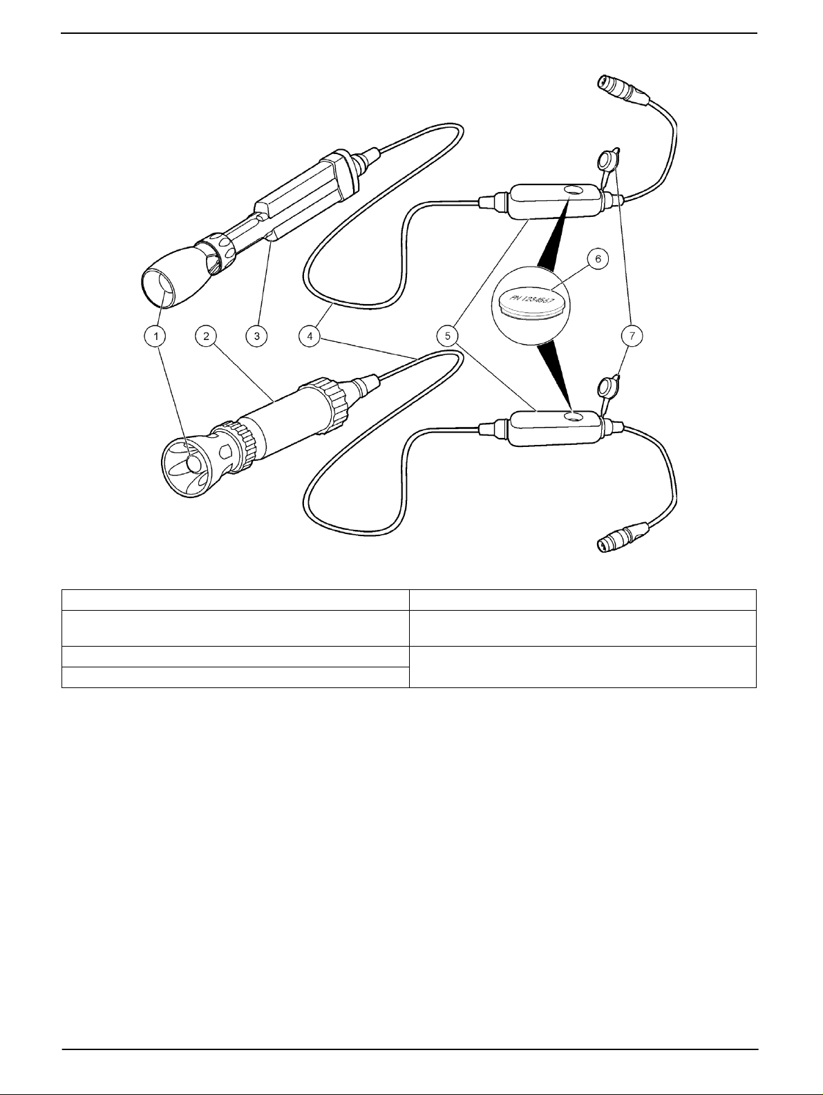
Figure 1 Probe overview
1 LDO sensor cap 5 Pressure sensor module
®
2 Rugged probe (5, 10, 15 or 30 meter cable) 6 iButton
Integrated Products, Inc.)
3 Standard probe (1 or 3 meter cable) 7 Pressure sensor module cap
4 Probe cable
(iButton is a registered trademark of Maxim
Preparation for use
1. Verify that the LDO sensor cap and iButton are installed correctly. Avoid touchi ng the
sensor cap with a hand, fingers or any surface that may scratch the cap.
Note: Make sure the LDO sensor cap and iButton have the same lot code and the iButton label
faces upward.
2. Rinse the sensor cap with deionized water and blot dry.
Note: The LDO sensor cap must be pre-conditioned if dissolved oxygen monitoring periods are
longer than 6 hours. Refer to Maintenance on page 6.
2 DOC272.53.80021
Page 3
Calibration
Before calibration:
The probe must have the correct service-life time stamp. Set the date and time in the meter before attaching the probe.
The LDO101 probe is factory calibrated, ships with an iButton-provided calibration and is ready for use. The factory
calibration will not allow a user calibration. To enable calibration, select User Cal as the Current Method in the LDO101
settings menu and follow the 100% (water-saturated air) procedures below.
It is not necessary to recalibrate when moving a calibrated probe from one HQd meter to another if the additional meter is
configured to use the same calibration options. If the additional HQd meter uses different calibration options (e.g. calibration
standards or acceptance criteria), calibrate the probe or change the method settings to select a different method. If using
Factory Cal, a new method will need to be created.
To view the current calibration, select the DATA LOG key, View Probe Data, then View Current Calibration
Tighten the probe locking nut securely when connecting the probe to the meter.
For probes that are continuously immersed in aqueous solutions, condition the sensor cap for 72 hours. Refer to
Maintenance on page 6.
If any two probes are connected, Push the UP or DOWN arrow to change to the single display mode in order to show the
Calibrate option.
A new method can be created if custom calibration or measurement settings are desired.
Refer to Troubleshooting on page 11 for calibration errors.
% saturation or mg/L calibration methods are available in the Modify Current Settings menu.
Water-saturated air (100%) calibration
Calibration notes
• Probes are initially calibrated at the factory. However , regular calibration by the user is
recommended for the best measurement accuracy.
• To calibrate rugged probes, use a wide neck bottle or flask (such as a 250 mL
Erlenmeyer flask).
• If the sensor cap is wet, carefully dry the cap with a nonabrasive cloth and put the
probe back in the bottle.
• An additional zero point calibration can be added to the calibration routine. Refer to
Change calibration options on page 10.
• The slope value is the comparison between the latest calibration and the factory
calibration expressed as a percentage. If the calibration slope does not meet the
acceptance criteria, the display will show Slope out of range. Refer to
Troubleshooting on page 11.
• Data is stored automatically in the data log when Press to Read or Interval is
selected while in Measurement Mode. When Continuous is selected, data is stored
only when the Store key is pushed.
• The calibration is recorded in the probe and the data log. The calibration is also sent
to a PC, printer or flash memory stick, if connected.
DOC272.53.80021 3
Page 4
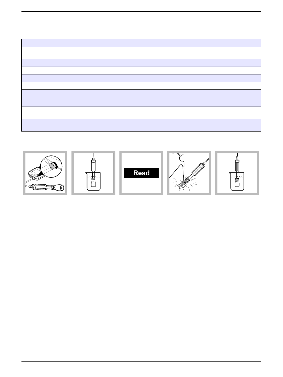
Note: Procedures also apply for rugged model probes.
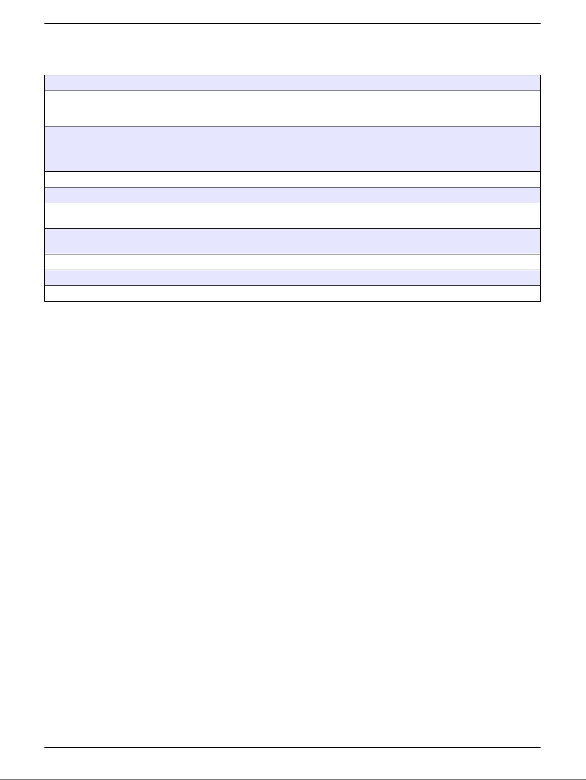
1. Connect the
probe to the meter.
The LDO101 probe
contains a factory
calibration. Remove
the shroud from the
probe.
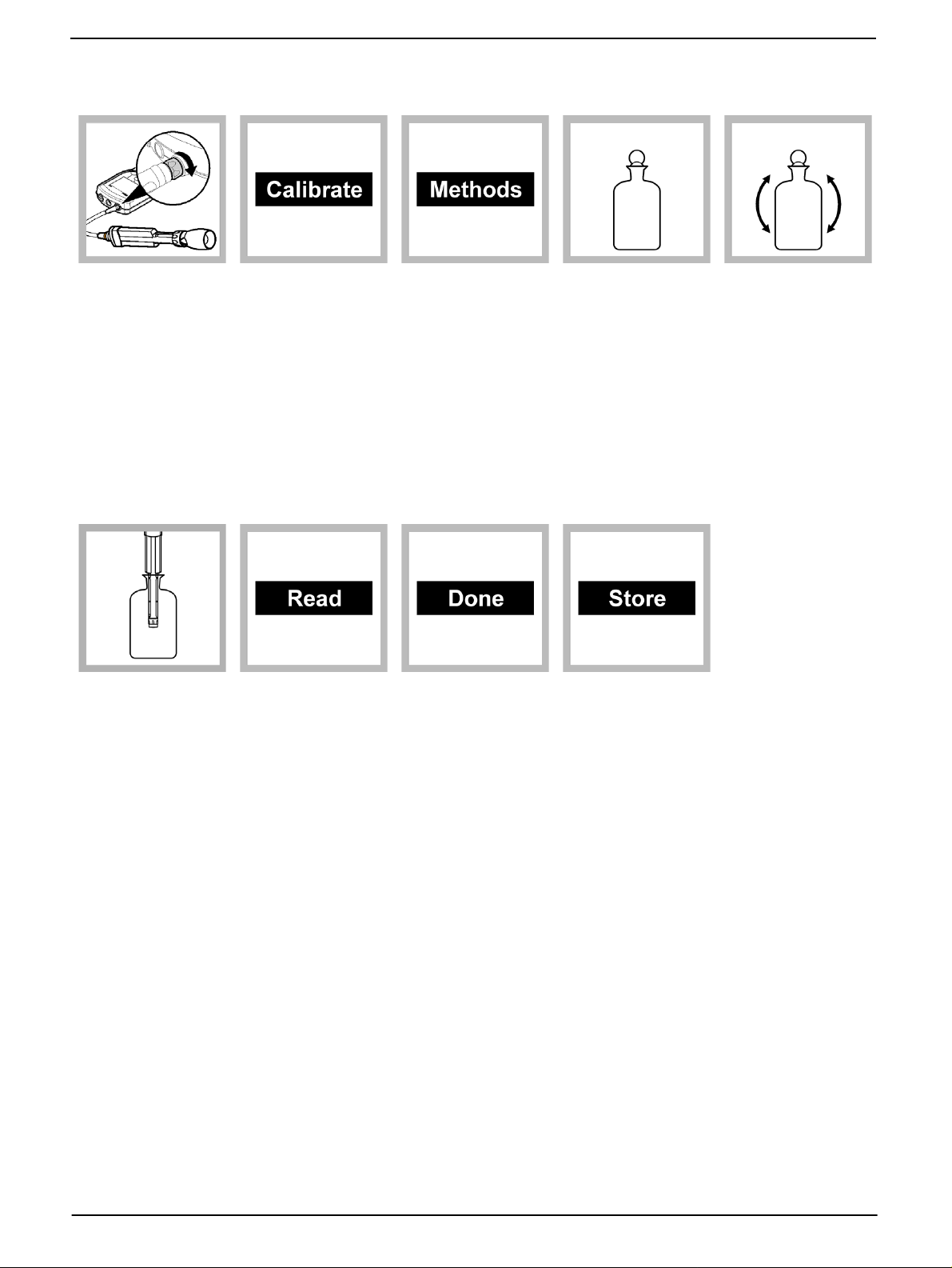
6. Remove the
stopper. Carefully
dry the cap with a
non-abrasive cloth
and place the probe
in the bottle.
2. Push the
CALIBRATE key to
create a new method
to enable user
calibration.
7. Select Read.
The display will
show Stabilizing...
and a progress bar
as the probe
stabilizes. The
display will highlight
the standard value.
3. Push the
METHODS key, and
select User Cal 100%. Push
OK.
8. Select Done to
view the calibration
summary.
4. Add
approximately ¼
inch (6.4 mm) of
reagent water to a
narrow-neck bottle,
such as a BOD
bottle.
9. Select Store to
accept the
calibration and
return to the
measurement mode.
Install the shroud on
the probe body.
5. Insert a stopper
and shake
vigorously for
approximately 30
seconds to saturate
the entrapped air
with water. Allow up
to 30 minutes for
contents to
equilibrate to room
temperature.
4 DOC272.53.80021
Page 5
Measurement
Before measurement:
The probe must have the correct service-life time stamp. Set the date and time in the meter before attaching the probe.
The probe is factory calibrated and ready for use. For applications that require greater accuracy and precision, perform a
user calibration (Calibration on page 3).
When connecting the probe to the meter, make sure to securely tighten the probe locking nut.
If complete traceability is required, enter a sample ID and operator ID before measurement.
Refer to Troubleshooting on page 11 for measurement errors.
Optimal response time performance is achieved when sample is stirred or probe is placed in flowing conditions.
To deploy the rugged probe at a distance, toss the probe body with a gentle underhand throw. Do not swing the probe by the
cable as this may cause injury to the user, will cause severe strain on the cable and will shorten the service life of the cell.
Damage under these conditions is not covered by the product warranty.
Data is stored automatically in the data log when Press to Read or Interval is selected while in the measurement mode.
When Continuous is selected, data will only be stored when Store is selected.
Salinity affects the concentration of dissolved oxygen in the sample. To correct for salinity effects, refer to Advanced
operation on page 8, or follow the Auto salinity correction (optional for HQ40d meter) procedures.
Note: Procedures also apply for rugged model probes.
1. Connect the
probe to the meter.
Calibrate the probe if
accuracy better than
± 0.50 mg/L is
required for the
application (refer to
Calibration on
page 3.).
2. Place the probe
in the sample and
stir gently or add a
stir bar. Move the
probe up and down
to remove any air
bubbles from the
sensor cap.
3. Select Read.
The display will
show Stabilizing...
and a progress bar
as the probe
stabilizes in the
sample. The display
will then show the
lock icon and the
4. Rinse the probe
with deionized water
and blot dry with a
laboratory wipe.
result will be
automatically stored
in the data log.
Auto salinity correction (optional for HQ40d meter)
Dissolved substances affect the amount of oxygen water can hold. Manually input salinity
settings for the most accurate dissolved oxygen measurements or use the Auto Salinity
Correction feature. The Auto Salinity Correction measures dissolved oxygen through the
connection of one LDO101 probe and one CDC401 conductivity cell (set to Salinity
parameter). The value obtained by the CDC4 01 conductivity cell automa tically adju st s the
salinity value for the LDO101 series probe. Auto Salinity Correction is recommended for
dissolved oxygen measurements in samples where salinity varies. Salinity units are
represented as parts per thousand (ppt) or (
1. Connect the LDO101 probe and CDC401 conductivity cell to the HQd meter. Turn the
meter on.
º
/ºº).
5. Repeat steps 2.
to 4. for additional
measurements.
Note: Security options must be turned off to enable auto salinity correction.
DOC272.53.80021 5
Page 6

2. Push METER OPTIONS and select the CDC401 Settings.
3. Select Current Method then Hach Salinity. Select
Note: To change additional measurement options, choose Modify Current Settings, change the
parameter to Salinity and any other desired settings.
OK.
4. Push EXIT until returned to the Full Access Options menu.
5. Select the LDO101 Settings, Modify Current Settings, Measurement Options,
Salinity Correction: Off, then Sal Correction Mode: Off. Arrow down to Auto (*) -
Use CDC401 and select OK.
6. Push
EXIT until the meter returns to the measurement mode. The HQ40d meter is now
set up to automatically use the salinity values obtained by the CDC401 with the
LDO101 probe. If the salinity value is out of range, the display will show *S= ----. This
will appear above the dissolved oxygen reading as shown in Figure 2.
Note: The asterisk (*) indicates that salinity is automatically correcting the dissolved oxygen value.
No asterisk indicates that salinity is being manually corrected. Warning messages will override the
asterisk (*) priority.
Maintenance
Figure 2 Salinity value out of range
Storage
Dry storage is recommended when the probe is used for measurements of short duration
(less than 6 hours). Wet storage is required for monitoring periods longer than 6 hours.
During the initial 72 hours of submersion in tap water, calibrate once every 8 hours. After
72 hours of storage in tap water, the sensor cap will reach a fully hydrated state. The need
for recalibration is minimized if the sensor cap is kept wet. Rugged probes may be stored
with the shroud installed if the storage container is sufficiently large.
Sensor cap maintenance
Sensor cap replacement is required every 365 days or more often if the cap becomes
damaged or fouled. The meter will display a reminder message when 30 days of sensor
service life remain on the cap. For LDO sensor cap replacement instructions, refer to the
instructions provided with the LDO sensor cap replacement kit.
Rugged probe maintenance
The shroud protects the sensor element s during rugged applications. Damage to the
sensing elements can occur if the shroud is not installed during field use. Damage under
these conditions is not covered under warranty. Before a rugged probe can be cleaned,
the shroud must be removed. Install the shroud after the probe is clean.
6 DOC272.53.80021
Page 7

Figure 3 Sensor exploded view
1 Shroud 7 Cap seal
2 Locking ridges (8x) 8 Temperature sensor
3 Locking ring 9 Locking groove
4 Sensor cap 10 Locking ribs (4x)
5 O-ring 11 Locking rib
6 Sensor lens
DOC272.53.80021 7
Page 8

To remove the shroud
1. Unscrew the locking ring.
2. Slide the shroud and locking ring off the pr obe.
To install the shroud
1. Place the locking ring on the probe body with the threads toward the sensor cap.
2. Slide the shroud on the probe until it is seated in the locking groove (rugged) or ribs
(standard). Slide the standard probe shroud on the standard probe until the inside
locking ridges align halfway between the ribs on the probe. Rotate slightly until the
shroud is seated (Figure 3).
3. Firmly tighten the locking ring onto the shroud.
To clean the probe
• Gently clean the sensor cap with a mild detergent, water and a soft cloth or cotton
swab. Do not remove the black colored substrate from the sensor cap.
• If water is present between the sensor cap and lens, remove the cap and blot dry the
sensor cap and lens with a soft dry cloth. Install the sensor cap.
Advanced operation
Parameter-specific settings can be changed through the Full Access Options menu.
Details about menu navigation, available opti ons and how to change them are given in the
screens, tables and procedures throughout this section.
The settings that can be changed are shown in Table 1.
.
Table 1Parameter-specific settings
Setting Options Description
• Defines measurement resolution
• Upper and lower measurement limits
• Value for salinity correction
• Atmospheric pressure units
• How often the meter calculates an
average readings
• Primary unit of measurement
Measurement options
Units
• Resolution
• Measurement limits
• Salinity correction
• Pressure units
• Averaging interval
• mg/L
• %
8 DOC272.53.80021
Page 9

Table 1Pa rame te r-s pe c ifi c se tt in g s
Setting Options Description
• User 100%
• User 100% with 0
• Calibration
Calibration options
• Calibration reminder
• User mg/L
• User mg/L with 0
• Factory
• Reminder repeat: Off, 8 h, 12 h, 1 d,
2 d, 5 d, 7 d
• Calibration expires: Immediately,
• Reminder + 30 m, Reminder + 1 h,
Reminder + 2 h, Continue Reading
Change measurement options
Methods are groups of default or user defined settings relevant to specific applications. If
the meter is set to the default method and the Modify Current Settings option is chosen, a
prompt will display to name the method after changes are entered. The settings are saved
with this name to distinguish them from the default method settings, which cannot be
changed. A saved method can be used instead of repeatedly adjusting individual settings.
Changes made to a user defined method are automatically saved with the existing name.
Multiple methods can be saved for the same probe.
There are three default methods provided for the LDO101 probe:
• Factory Cal (Calibration with default LDO calibration)
• User Calibration—100% (allows user calibration)
• Default
1. Make sure a probe is connected to the meter.
2. Push the
METER OPTIONS key and select (Probe Model) Settings.
3. Select Modify Current Settings.
4. Select Units to change the units to mg/L (default) or to %.
5. Select Measurement Options.
6. Update the settings:
Table 2 Measurement options settings
Setting Options Description
0.1—Fast (0.35 mg/L)/min
Resolution
Measurement
limits
0.01—Fast (0.35 mg/L)/min
0.01—Medium (0.15 mg/L)/min
(default)
0.01—Slow (0.05 mg/L)/min
Lower limit (default: 0.0 mg/L; 0%)
Upper limit (default: 20.0 mg/L;
200%)
The resolution affects the number of decimal places and
the stabilization time. Higher resolution measurements take
more time to stabilize.
The measurement limits can be set to match the acceptable
values for the sample. When the measurement is above the
upper limit setting or below the lower limit setting, the meter
will show an "Out of limits" message. This message is an alert to a
potential problem with process conditions.
DOC272.53.80021 9
Page 10

Table 2 Measurement options settings (continued)
Setting Options Description
Salinity lowers the solubility of dissolved oxygen in water.
Off (default)
Salinity
correction
Salinity value ‰ (default: 35.0 ‰)
Pressure units
Averaging
interval
Note: Labels and options may vary depending on the units selected.
Manual
Auto (connect conductivity
probe)
hPa
mBar
inHg
mmHg
Off
30 seconds
60 seconds
90 seconds
3 minutes
5 minutes
To correct for salinity in the sample, set salinity correction
to manual and then enter the salinity value.
Note: When the HQ40d meter is used, a conductivity probe can also
be connected for automatic salinity measurement and correction. The
parameter setting for the conductivity probe must show salinity.
When salinity correction is set to manual, enter the salinity
value of the sample. Salinity can be measured with a
conductivity probe.
The meter shows the atmospheric pressure at the current
elevation, which is necessary for accurate measurements.
This pressure reading will not agree with readings from
sources such as weather stations, which report atmospheric
pressure at sea level.
The averaging interval is useful for samples that contain a
lot of air bubbles, for example in an aeration basin. The air
bubbles cause the dissolved oxygen readings to vary greatly
from one reading to the next. To make the readings more
consistent, increase the averaging interval. The meter will
take measurements at the same frequency but show only
the average over a longer interval.
7. If prompted, enter a name for the new method settings. Additional changes made to
the settings of an existing method are automatically saved with the same method
name.
8. Push
EXIT until the meter returns to the measurement mode.
Change calibration options
1. Make sure a probe is connected to the meter.
2. Push the
3. Select Modify Current Settings.
4. Select Calibration Options.
5. Update the settings:
METER OPTIONS key and select (Probe Model) Settings.
10 DOC272.53.80021
Page 11

Table 3 Calibration option settings
Setting Option Description
User—100% Water-saturated air (100%) calibration
User—100% with 0 Water-saturated air (100%) calibration with 0 point
Calibration
Standard value Adjustable
Calibration reminder
User—mg/L
User—mg/L with 0
Factory Calibration with default LDO calibration
Reminder Repeat Off, 8 h, 12 h, 1 d, 2 d, 5 d, 7 d
Expires
Allows calibration with specified dissolved oxygen
concentration (mg/L) solution
Allows calibration with specified dissolved oxygen
concentration (m/L) solution with 0 point
Use arrow keys to specify the concentration of the solution
that will be used for calibration (if mg/L calibration mode is
selected).
Immediately, Reminder + 30 min, Reminder + 1 h, Reminder +
2 h, Continue Reading
6. If prompted, enter a name for the new method settings. Additional changes made to
the settings of an existing method are automatically saved with the same method
name.
Troubleshooting
Message or
symptom
Probe not supported
Connect a probe or
Probe requires
service
Out of range
Possible cause Action
Software not updated
HQd meter does not support IntelliCAL
probe
Probe not connected properly
Large number of methods stored on
probe
Software not updated
Damaged probe
Sensor cap loose, scratched or
damaged
Temperature and/or pressure sensor
error
Damaged probe
Sample outside of specifications
iButton number does not match sensor
cap lot number
Sensor cap exposed to direct sunlight Install the protective shroud
7. Push
EXIT until the meter returns to the meas ur em e nt mod e .
Update the HQd software to the newest revision at
www.hach.com/SoftwareDownloads. Refer to the HQd
Series meter manual.
Contact a Hach Technical Support Representative.
Disconnect, then connect the probe. Tighten the locking
nut.
Continue to let probe connect. Do not disconnect the
probe. See the HQd Series meter manual.
Update the HQd software to the newest revision at
wwwhach.com/SoftwareDownloads. Refer to the HQd
Series meter manual.
Verify connectivity with another probe or meter to confirm
isolated issue with probe. Contact a Hach Technical
Representative.
Reposition or replace the LDO sensor cap
Verify that both temperature and pressure sensors are
reading correctly
Verify both blue and red LEDs are illuminated on the
probe. If not, replace the probe or contact a Hach
Technical Representative.
Verify that the sample concentration, temperature and
pressure are within the range of the LDO101 probe.
Replace the iButton or sensor cap or perform a user
calibration
1
DOC272.53.80021 11
Page 12

Troubleshooting (continued)
Message or
symptom
Slope out of range
LDO–calibration not
supported (factory
calibration)
Sensor 0 days
O
2
remaining
Sensor ## of days
O
2
remaining
Calibration failed:
outside of acceptance
criteria/Temperature
out of range/Offset
out of limits
Possible cause Action
Probe not prepared for sample
Calibration method settings
Sensor cap loose, scratched or
damaged
Temperature and pressure errors
LED lights do not function Contact a Hach Technical Representative (800-227-4224)
LDO method calibration option is set to
Factory.
There are 0 days remaining in the life of
the LDO sensor cap
Meter set to incorrect date and time
Software not updated
There are 30 days or fewer remaining in
the life of the LDO sensor cap.
Water Saturated air equilibration not
reached
Sensor cap loose, scratched, or
damaged
Temperature and/or pressure sensor
error
Damaged probe
Allow probe to reach equilibrium in a water-saturated air
environment and repeat calibration.
Verify that the calibration standards in the method are
correct.
Locate and install the iButton that matches the sensor cap
and replace the sensor cap.
Verify temperature and pressure are reading accurately.
Contact a Hach Technical Representative.1
If user calibration is desired, change settings in Cal
options. Refer to Calibration on page 3.
Replace the LDO sensor cap. Calibration will be allowed,
however the calibration icon and question mark will
appear on the measurement screen even if the calibration
has passed.
Disconnect the probe from the meter. Set the correct date
and time in the Meter Options menu. Connect the probe
and verify that the message has been removed.
Update the HQd software to the latest version and test
again.
Replace the LDO sensor cap soon.
Allow longer equilibration time
Reposition or replace the LDO sensor cap
Verify that bot h temperature and pressure sensors are
reading correctly and within range.1
Verify both blue and red LEDs are illuminated on the
probe. If not, replace the probe or contact a Hach
Technical Representative.
1
The pressure as measured by the LBOD or LDO is what is referred to as atmospheric pressure and is not corrected to sea
level. Weather station pressures are reported at sea level and commonly referred to as mean sea level pressure. As a result
the LBOD or LDO will not read the same as most household or professional barometers or weather station reports (which are
compensated) unless reported at sea level. In order to compare the pressure results obtained from the LBOD or LDO probe
barometers and these compensated barometers, it is necessary to first compensate the pressure reported by the probes
mathematically.
12 DOC272.53.80021
Page 13

Replacement parts
Description
IntelliCAL LDO probe, standard, with 1 m cable 1 LDO10101
IntelliCAL LDO probe, standard, with 3 m cable 1 LDO10103
IntelliCAL LDO probe, rugged, with 5 m cable 1 LDO10105
IntelliCAL LDO probe, rugged, with 10 m cable 1 LDO10110
IntelliCAL LDO probe, rugged, with 15 m cable 1 LDO10115
IntelliCAL LDO probe, rugged, with 30 m cable 1 LDO10130
Quantity Item Number
Accessories
Description
BOD bottle (300 mL) 1 62100
BOD bottle (300 mL) 6/pkg 62106
Citizen PD-24 USB handy printer, 120-220 VAC 1 2960100
Color coded probe clips (5 color coded sets) 10/pkg 5818400
Erlenmeyer flask 250 mL 2089846
Field kit (Includes glove kit, and five 120 mL
sample cups)
Glove kit only for HQd meters 1 5828700
LDO sensor cap, replacement (includes iButton,
cap seal and probe tip o-ring)
Meter stand 1 4754900
Printer paper for PD-24, thermal 5/pk 5836000
USB and AC power adapter for HQd meters
(included with the HQ40d)
USB keyboard for HQd meters (must have
5826300)
Quantity Item Number
1 5825800
1 581 1200
1 5826300
1LZV582
Rugged probe accessories
Probe depth marker (rugged cable markers) 5/pk 5828610
Replacement shroud kit, rugged LDO probe 1 5825900
Rugged field case for 2 probes with up to 5 m
cables (10 m total). Includes: Empty case and
insert for meter and probe storage, (4) containers
for sample collection
Rugged field case for three probes with up to 5
m cables (15 m total). Includes same
accessories as case 8505500.
Rugged field case for probes with > 5 m cables
(30 m total). Includes: Empty case and insert for
meter and two probe storage cavities, space for
storage of HQd meter with protective glove
Standard probe accessories
IntelliCAL standard probe stand 1 8506600
Replacement shroud kit, standard LDO each 5832500
Standard probe holder (use with protective glove) 1 5829400
1 8505500
1 8505501
1 8505600
DOC272.53.80021 13
Page 14

HACH Company World Headquarters
P.O. Box 389
Loveland, Colorado 80539-0389 U.S.A. International customers:
Tel (800) -227-4224 (U.S.A. only) Tel +001 (970) 669-3050
Fax (970) 669-2932 Fax +001 (970) 669-2932
orders@hach.com • www.hach.com intl@hach.com
© Hach Company,2009. All rights reserved. Printed in the U.S.A. Edition 1, May 2009
 Loading...