

Page 1

DOC023.53.93065
Hach 9523 pH Calculator
08/2013, Edition 2
User Manual
Page 2

Page 3

Table of Contents
Specifications..............................................................................................................3
General information..................................................................................................3
Safety information........................................................................................................4
Use of hazard information............................................................................................ 4
Precautionary labels ...................................................................................................4
EMC compliance statement (Korea)............................................................................5
Product overview.........................................................................................................5
Principle of operation (pH calculation)..................................................................6
Measurement of pH by differential conductivity....................................................6
Installation.....................................................................................................................7
Inspection....................................................................................................................7
Unpacking....................................................................................................................7
Installation considerations...........................................................................................7
Mechanical installation................................................................................................. 7
Install analyzer...................................................................................................... 7
Resin cartridge installation...................................................................................9
Hydraulic connections........................................................................................10
Electrical installation...........................................................................................10
Analyzer startup.........................................................................................................10
Operation.....................................................................................................................11
User navigation..........................................................................................................11
System setup.............................................................................................................11
Resin option...............................................................................................................11
Sensor configuration and calibration.........................................................................11
Maintenance...............................................................................................................11
Controller...................................................................................................................11
Service schedule.......................................................................................................11
Resin replacement.....................................................................................................12
Cartridge replacement process..........................................................................12
Resin replacement kit.........................................................................................13
Troubleshooting.......................................................................................................14
Controller...................................................................................................................14
Analyzer.....................................................................................................................14
Sensor diagnostic and test menu..............................................................................14
Spare parts and accessories..............................................................................14
Material safety data sheets (MSDS).................................................................15
MSDS - Cationic resin...............................................................................................15
1
Page 4

Table of Contents
2
Page 5

Specifications
Specifications are subject to change without notice.
Specification Details
Ambient temperature 0—60 °C (32—140 °F)
Relative humidity 10—90%
Power supply voltage fluctuation ± 10%
Over voltage category 2 (in accordance with standard EN 61010-1)
Pollution degree 2 (in accordance with standard CEI 664)
Altitude < 2000 m
Measurement category Class 1 (overvoltage < 1500V)
Power requirements
European standards EN 61326-1: 2006; EN 61010-1: 2010
ETL approved File 65454
Dimensions
Weight Controller: 1.7 kg (3.75 lb); Analyzer: 7 kg (15.43 lb)
Controller enclosure NEMA 4X/IP66 metal enclosure with a corrosion-resistant finish
Analyzer housing material Polyester
Mounting types Controller: Wall, pipe or panel; Analyzer: Wall
2 electrode sensor
(cell constant: 0.01 cm-1)
Display resolution
Display range
Accuracy ± 1% of displayed value; temperature < ± 0.2 °C
Calculated pH
Sample flow 5—20 L/h
Temperature sensor Pt 100
AC powered controller: 100-240 VAC ±10%, 50/60 Hz
24 VDC powered controller: 24 VDC—15%, + 20%
Controller: 144 x 144 x 181 mm (5.7 x 5.7 x 7.1 in.);
Analyzer: 748 x 250 x 236 mm (29.4 x 9.8 x 9.3 in)
Conductivity range: 0.01 μS/cm—200 μS/cm;
Resistivity range: 5k Ω.cm—100 MΩ.cm
Conductivity/resistivity: automatic point drift (min. resolution 0.001 μS/cm)
< 0.1 °C
NH3; 7 < pH < 10; 2.8 μS/cm < C1 < 28 μS/cm; C2 < 0.5 μS/cm
NaOH; 7 < pH < 10.7; 2.5 μS/cm < C1 < 125 μS/cm; C2 < 100μS/cm
Accuracy on conductivity measurement: ± 2%;
Max difference calculated-theoretical value: 0.1 pH
General information
In no event will the manufacturer be liable for direct, indirect, special, incidental or consequential
damages resulting from any defect or omission in this manual. The manufacturer reserves the right to
make changes in this manual and the products it describes at any time, without notice or obligation.
Revised editions are found on the manufacturer’s website.
English
3
Page 6
Safety information
N O T I C E
The manufacturer is not responsible for any damages due to misapplication or misuse of this product including,
without limitation, direct, incidental and consequential damages, and disclaims such damages to the full extent
permitted under applicable law. The user is solely responsible to identify critical application risks and install
appropriate mechanisms to protect processes during a possible equipment malfunction.
Please read this entire manual before unpacking, setting up or operating this equipment. Pay
attention to all danger and caution statements. Failure to do so could result in serious injury to the
operator or damage to the equipment.
Make sure that the protection provided by this equipment is not impaired. Do not use or install this
equipment in any manner other than that specified in this manual.
Use of hazard information
D A N G E R
Indicates a potentially or imminently hazardous situation which, if not avoided, will result in death or serious injury.
Indicates a potentially or imminently hazardous situation which, if not avoided, could result in death or serious
injury.
Indicates a potentially hazardous situation that may result in minor or moderate injury.
Indicates a situation which, if not avoided, may cause damage to the instrument. Information that requires special
emphasis.
W A R N I N G
C A U T I O N
N O T I C E
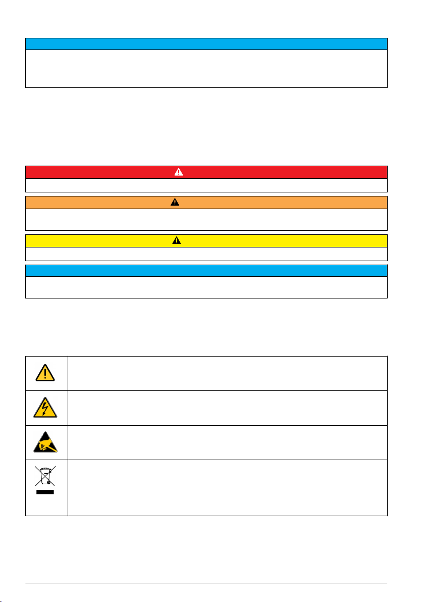
Precautionary labels
Read all labels and tags attached to the product. Personal injury or damage to the product could
occur if not observed. A symbol on the instrument is referenced in the manual with a precautionary
statement.
4 English
This symbol, when noted on a product, indicates a potential hazard which could cause serious
personal injury and/or death. The user should reference this instruction manual for operation and/or
safety information.
This symbol, when noted on a product enclosure or barrier, indicates that a risk of electrical shock
and/or electrocution exists and indicates that only individuals qualified to work with hazardous
voltages should open the enclosure or remove the barrier.
This symbol, when noted on the product, indicates the presence of devices sensitive to electrostatic
discharge and indicates that care must be taken to prevent damage to them.
Electrical equipment marked with this symbol may not be disposed of in European public disposal
systems. In conformity with European local and national regulations, European electrical equipment
users must now return old or end-of-life equipment to the manufacturer for disposal at no charge to
the user.
Note: For return for recycling, please contact the equipment producer or supplier for instructions on how to return
end-of-life equipment, producer-supplied electrical accessories, and all auxiliary items for proper disposal.
Page 7
Products marked with this symbol indicates that the product contains toxic or hazardous substances
or elements. The number inside the symbol indicates the environmental protection use period in
years.
Products marked with this symbol indicates that the product conforms to relevant South Korean
EMC standards.
EMC compliance statement (Korea)
Type of equipment Additional information
A 급 기기
( 업무용 방송통신기자재 )
Class A equipment
(Industrial Broadcasting and Communication
Equipment)
이 기기는 업무용 (A 급 ) 전자파적합기기로서 판매자 또
는 사용자는 이 점을 주의하시기 바라며, 가정외의 지역
에서 사용하는 것을 목적으로 합니다.
This equipment meets Industrial (Class A) EMC
requirements. This equipment is for use in industrial
environments only.
Product overview
The system is available as either a stand-alone controller or as a complete analyzer including the
controller. Refer to the controller documentation for information regarding the controller.
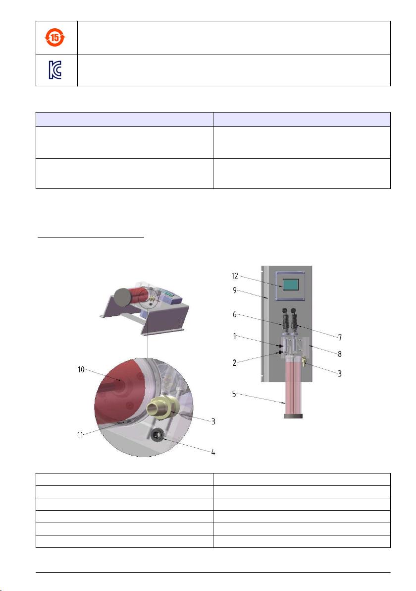
Figure 1 Analyzer overview
1 Degassing valve 7 Channel 2 conductivity probe
2 Sample flow adjustment valve 8 Measurement cell
3 Sample output 9 Mounting panel
4 Sample input 10 Quick lock with tube
5 Cationic resin cartridge 11 Flat gasket
6 Channel 1 conductivity probe 12 Controller
The system can be configured to function in numerous applications in the following industry sectors:
English
5
Page 8

• Measurement in pure and ultrapure water, power plants, semiconductor industry, pharmaceutical
• Drinking water
• Industrial processes (chemistry, paper mills, sugar refineries, etc.)
Principle of operation (pH calculation)
The Polymetron 9523 analyzer adheres to the recommendations contained in the guidelines for
feedwaters, boiler water and steam quality for power and industrial plants.
The pH calculations can only be applied under the following strict chemical conditions:
• The sample must only contain an alkaline agent (ammonia, sodium hydroxide or ethanolamine)
• Any impurity is principally NaCl (sodium chloride)
• The concentration of impurity must be negligible in comparison to the alkaline agent
Control of conductivity values
Control of the minimum and maximum conductivity values depends upon the volatile conditioner.
These values are illustrated in the following two tables.
Note: AVT (All Volatile Treatment) - Conditioning concept where only volatile alkalizing agents are used; mainly
ammonia.
NH3 Conditioner:
AVT
pH 7 - 10.0
Conductivity C1 (μS/cm) 2.8 - 28
Acid conductivity C2 (μS/cm) < 0.5
NaOH Conditioner:
AVT
pH 7 - 10.7
Conductivity C1 (μS/cm) 2.5 - 125
Acid conductivity C2 (μS/cm) < 100
Measurement of pH by differential conductivity
Measurement of pH in environments of low conductivity using the standard potentiometric method
(glass electrode + reference) is extremely delicate and not very accurate because it is proportional to
the concentration logarithm. It also requires a more frequent calibration to compensate for variations
in the measurement chain (junction potential, degradation of the glass membrane).
On the other hand, measurement of conductivity in these environments is a lot more reliable and
more accurate as it is directly proportional to the concentration in impurity, and in addition requires
little or no maintenance. Therefore, given the relationship between the pH and conductivity of a
product, the conductivity measurement can be used to determine a precise pH.
If the product contains impurities (generally in the form of salts), this calculation cannot be applied.
The principle is then to transform the salt into acid by passing it through a cationic resin and, given
the relationship of the conductivity between the acid and the corresponding salt (always around 3), to
determine the conductivity originating only from the conditioner:
ΔC = Conductivity before resin (C1) – Conductivity after resin (C2) / A
and
ph = f(ΔC)
Note: The calculated pH is the pH of the sample at the analyzer inlet (channel 1). The analyzer does not calculate
the pH downstream of the resin cartridge.
6
English
Page 9

Installation
W A R N I N G
Multiple hazards. Only qualified personnel must conduct the tasks described in this section of the document.
Inspection
The equipment has been factory tested and checked prior to shipping. We nevertheless recommend
that you perform a visual inspection in order to ensure that it has not been damaged. Any marked
packaging is a potential sign of damage that may not be immediately visible. Keep all packaging in
the event of claims. If any parts or accessories are missing, refer to your distributor or to Hach
Lange.
Unpacking
The equipment should be unpacked carefully. Make sure that no accessories are lost during
unpacking. If any parts or accessories are missing refer to your distributor or to Hach Lange.
Installation considerations
• Place the controller in an accessible location, preferably above eye-level allowing an unrestricted
view of the display and controls
• Vibrations are not excessive
• Choose a site where access to the equipment is easy
• Keep the sample tubing as short as possible to minimize lag time
• Do not place the sensor next to a heat source
• Ensure there is no air intrusion into the sample supply line
Mechanical installation
If the complete analyzer has been purchased follow the instructions in Install analyzer on page 7.
If only the controller was purchased, refer to the controller documentation for installation instructions.
Install analyzer
Personal injury hazard. The object is heavy. Make sure that the analyzer is securely attached to a wall for a safe
operation.
W A R N I N G
English 7
Page 10

Figure 2 Analyzer dimensions in mm [inches]
1. Mount the analyzer using 4 M6 screws to fix it securely in place.
2. The sensor for channel one is placed before the resin (on the left side as viewed from the front),
and for channel two after the resin (on the right side as viewed from the front).
8
English
Page 11

Resin cartridge installation
Figure 3 Resin cartridge installation
1. Insert the steel tube (B) into the quick lock connector (A).
2. Push the steel tube (B) as far as possible into the measuring cell (C).
3. Take the resin cartridge and turn it upside down 2 or 3 times until the resin comes away from the
sides of the cartridge and settles at the bottom, at the opposite end to the marker line.
4. Unscrew the cap off the top of the cartridge, by the marker line. Discard this cap and the flat black
sealing cap following the safety and disposal information for used cartridges.
5. Place the end of the steel tube into the center of the cartridge (D).
6. Slowly raise the cartridge to the measuring cell and screw into place to obtain an airtight and
watertight fitting.
English
9
Page 12

Hydraulic connections
Figure 4 Hydraulic connections
1 Degassing valve 4 Sample input - tubing 6 mm (standard) or 1/4 inch
2 Sample flow adjustment valve 5 Cationic resin cartridge
3 Sample output - tubing 12 mm or 1/2 inch
(with adapter)
1. The sample input and output connections use flexible tubing according to the following
specifications:
• Diameter: as specified above
• Material: polyethylene or PTFE or FEP
• Pressure: 0.2 to 6 bars (3 to 90 psi)
• Temperature: 5 to 50 °C (40 to 120 °F)
• Flow rate: 5 to 12 L/h
Insert the tubing into the quick release connections under the flow chamber block (positions 3 and
4 in Figure 4)
Electrical installation
For all wiring connections, including power, alarms, relays and analog outputs, refer to the controller
documentation for instructions.
Analyzer startup
1. Open the degassing valve.
2. Open the sample flow adjustment valve and ensure everything is watertight and there are no
leaks.
3. Close the degassing valve when the measuring cell is free of air.
4. Set the sample flow to the required rate (between 5 and 20 L/h).
5. Pass about 10 liters of sample through the resin to thoroughly rinse it and prepare the analyzer
for measurements.
10
English
Page 13

Operation
User navigation
Refer to the User interface and navigation section of the controller documentation for keypad
description and navigation information.
System setup
Refer to the System startup and Advanced operation sections of the controller documentation for
system setup information.
Resin option
Use the RESIN option to view and change the parameters related to the resin cartridge. These
parameters must be defined before the analyzer is used for the first time.
1. Push the menu key and select TEST/MAINT>RESIN.
2. To monitor the status of the resin select the TRACK option and push enter.
Option Description
YES Monitor the resin status. When the life expectancy of the resin is less than 10 days a warning
message is triggered. When the life expectancy reaches 0 days a system error is triggered.
NO The resin is not monitored.
3. To view the current status of the resin select the STATUS option and push enter. The date the
resin was last changed and the current life expectancy are displayed. Push back to return to the
menu or enter to reset the parameters.
4. To reset the resin parameters select PARAMETERS and push enter. Based on the values input,
the life expectancy of the resin is recalculated.
Option Description
CAPACITY Use the arrow keys to enter the resin exchange capacity (0.5 to 5.0 mole/liter).
VOLUME Use the arrow keys to enter the volume of resin (0.5 to 20 liters).
FLOW Use the arrow keys to enter the sample flow rate through the cartridge (2 to
CONCENTRATION Use the arrow keys to enter the resin concentration (0 to 20 ppm).
20 liters/hour).
Sensor configuration and calibration
Refer to the Operation section of the conductivity module documentation for contacting conductivity
sensor configuration and calibration information.
Maintenance
D A N G E R
Multiple hazards. Only qualified personnel should conduct the tasks described in this section of the manual.
Controller
Refer to the Maintenance section of the controller documentation.
Service schedule
The following table shows the recommended service schedule:
English
11
Page 14

Every
3 Months
Validation (check with referenced measure) X X X X
Calibration (measure) X X
Calibration (temperature) X
The following items are performed by the Hach Lange service group
Re-qualification (Inputs/Outputs) X
External audit X
Every
6 Months
Yearly As Needed
Resin replacement
Note: In order to take advantage of the full system specifications, we recommend the use of nuclear grade cationic
resin.
For this operation, you can either replace the existing cartridge of resin with a new one (part number
09523=A=7000) following the instructions in Cartridge replacement process on page 12, or keep
the cartridge and refill using the resin replacement kit (part number 09523=A=7010) and following the
instructions in Resin replacement kit on page 13.
Cartridge replacement process
1. Stop the sample flow using the sample flow adjustment valve (A).
2. Unscrew the used cartridge from the measuring cell and remove carefully by pulling down on the
cartridge until it clears the steel tube (B). The steel tube must remain in place.
3. Discard the used resin following the safety and disposal information for both the used resin and
used cartridges.
4. Take the new resin cartridge and turn it upside down 2 or 3 times until the resin comes away from
the sides of the cartridge and settles at the bottom, at the opposite end to the marker line.
5. Unscrew the cap off the top of the new cartridge, by the marker line. Discard this cap and the flat
black sealing cap following the safety and disposal information for used cartridges.
6. Place the end of the steel tube into the center of the cartridge (C).
12
English
Page 15

7. Slowly raise the new cartridge to the measuring cell and screw into place to obtain an airtight and
watertight fitting.
8. Open the degassing valve (D).
9. Open the sample flow adjustment valve and ensure everything is watertight and there are no
leaks.
10. Close the degassing valve when the measuring cell is free of air.
11. Set the sample flow to the required rate (between 5 and 20 L/h).
12. Modify the resin parameters (see Resin option on page 11).
Resin replacement kit
1. Stop the sample flow using the sample flow adjustment valve (A).
2. Unscrew the used cartridge from the measuring cell and remove carefully by pulling down on the
cartridge until it clears the steel tube (B). The steel tube must remain in place.
3. Discard the used resin following the safety and disposal information for both the used resin and
used cartridges.
4. Fill the cartridge with the new resin up the marker line (C), adding demineralized water at regular
intervals to compact the resin.
5. Take the cartridge and place the end of the steel tube into the center (D).
6. Slowly raise the cartridge to the measuring cell and screw into place to obtain an airtight and
watertight fitting.
7. Open the degassing valve (E).
8. Open the sample flow adjustment valve and ensure everything is watertight and there are no
leaks.
9. Close the degassing valve when the measuring cell is free of air.
English
13
Page 16

10. Set the sample flow to the required rate (between 5 and 20 L/h).
11. Modify the resin parameters (see Resin option on page 11).
Troubleshooting
Controller
Refer to the Troubleshooting section of the controller documentation for detailed information.
Analyzer
Refer to the Troubleshooting section of the conductivity module documentation for detailed
information.
Sensor diagnostic and test menu
The sensor diagnostic and test menu shows current and historical information about the instrument.
Refer to Table 1.
Table 1 Sensor DIAG/TEST menu
Option Description
MODULE INFORMATION Shows information about the sensor module.
SENSOR INFORMATION Shows the name and serial number that was entered
CAL DAYS Shows the number of days since the last calibration.
CAL HISTORY Shows a list of all calibrations by date/time stamp. Use
RESET CAL HISTORY Resets the calibration history for the sensor (requires
POLARIZATION Contacting conductivity sensors only. Shows
SENSOR SIGNALS Shows the current sensor signal information.
FACTORY CAL Reserved for service technicians only.
DIAG MEAS Shows diagnostic information about the current
by the user.
the arrows keys to select a calibration and push enter
to view the details.
service-level passcode). All previous calibration data is
lost.
information about the electrode polarization, the cable
capacitance and the time before the next
measurement.
measurement.
Spare parts and accessories
Note: Product and article numbers may vary for some selling regions. Contact the appropriate distributor or refer to
the company website for contact information.
Description Item no.
Conductivity probe 08310=A=0000
Cable for 8310 probe (1 meter) 09123=A=8001
Dual measurement cell 09523=C=0100
Sample flow adjustment valve 09184=C=4010
O-Ring for flow regulation valve 429=042=019
14 English
Page 17

Description Item no.
Outlet quick connector 583=012=012
Spare resin cartridge complete with resin 09523=A=7000
Viton flat gasket 09123=C=0500
Cationic resin cartridge (empty) 09523=C=0200
Resin cartridge closure 09523=C=0300
Sample outlet tube (1 meter) 359110,52012
Cationic resin (2 liters) 09523=A=7010
Material safety data sheets (MSDS)
MSDS - Cationic resin
The information listed below corresponds to our current state of knowledge. They serve as a
description of the products in regard to necessary safety measures and do not guarantee the
described chemical properties. These indications describe the safety precautions to take against the
related product and they are not a guaranty of the described product properties.
1. IDENTIFICATION OF THE SUBSTANCE
Product name: LEWATIT S 100 G1
2. COMPOSITION / INFORMATION ON INGREDIENTS
CAS no: 69011-20-7
Styrene-divinylbenzene-copolymer with sulphonic acid groups in H-form - 45-50% (weight)
3. HAZARDS IDENTIFICATION
Risk of serious damage to eyes.
4. FIRST AID MEASURES
Inhalation: Move exposed person to fresh air. Keep person warm and at rest. If not breathing, if breathing is
irregular or if respiratory arrest occurs, provide artificial respiration or oxygen by trained personnel. It may be
dangerous to the person providing aid to give mouth-to-mouth resuscitation. Get medical attention if adverse
health effects persist or are severe. If unconscious, place in recovery position and get medical attention
immediately. Maintain an open airway. Loosen tight clothing such as a collar, tie, belt or waistband.
Ingestion: Wash out mouth with water. Move exposed person to fresh air. Keep person warm and at rest. If
material has been swallowed and the exposed person is conscious, give small quantities of water to drink. Stop if
the exposed person feels sick as vomiting may be dangerous. Do not induce vomiting unless directed to do so by
medical personnel. If vomiting occurs, the head should be kept low so that vomit does not enter the lungs. Get
medical attention if adverse health effects persist or are severe. Never give anything by mouth to an unconscious
person. If unconscious, place in recovery position and get medical attention immediately. Maintain an open
airway. Loosen tight clothing such as a collar, tie, belt or waistband.
Skin contact: Flush contaminated skin with plenty of water. Remove contaminated clothing and shoes. Get
medical attention if symptoms occur. Wash clothing before reuse. Clean shoes thoroughly before reuse.
Eye contact: Get medical attention immediately. Immediately flush eyes with plenty of water, occasionally lifting
the upper and lower eyelids. Check for and remove any contact lenses. Continue to rinse for at least 10 minutes.
Chemical burns must be treated promptly by a physician.
English 15
Page 18

5. FIRE FIGHTING MEASURES
Extinguishing media: In case of fire, use water spray (fog), foam, dry chemical or CO2.
Fire-fighters should wear appropriate protective equipment and self-contained breathing apparatus (SCBA) with a
full face-piece operated in positive pressure mode.
6. MEASURES IN CASE OF ACCIDENTAL SPILLAGE
No action shall be taken involving any personal risk or without suitable training. Keep unnecessary and
unprotected personnel from entering. Do not touch or walk through spilt material. Provide adequate ventilation.
Put on appropriate personal protective equipment (see Section 8).
Avoid dispersal of spilt material and runoff and contact with soil, waterways, drains and sewers. Inform the
relevant authorities if the product has caused environmental pollution (sewers, waterways, soil or air).
Move containers from spill area. Vacuum or sweep up material and place in a designated, labelled waste
container. Dispose of via a licensed waste disposal contractor.
Move containers from spill area. Prevent entry into sewers, water courses, basements or confined areas. Vacuum
or sweep up material and place in a designated, labelled waste container. Dispose of via a licensed waste
disposal contractor.
7. HANDLING AND STORAGE
Put on appropriate personal protective equipment (see Section 8). Eating, drinking and smoking should be
prohibited in areas where this material is handled, stored and processed. Workers should wash hands and face
before eating, drinking and smoking. Do not get in eyes or on skin or clothing. Do not ingest. Keep in the original
container or an approved alternative made from a compatible material, kept tightly closed when not in use. Empty
containers retain product residue and can be hazardous.
Store between the following temperatures: -20 to 40 °C (-4 to 104 °F). Store in accordance with local regulations.
Store in original container protected from direct sunlight in a dry, cool and well-ventilated area, away from
incompatible materials (see section 10) and food and drink. Keep container tightly closed and sealed until ready
for use. Containers that have been opened must be carefully resealed and kept upright to prevent leakage. Do
not store in unlabelled containers. Use appropriate containment to avoid environmental contamination.
Take precautionary measures against electrostatic discharges. Do not allow to dry out.
8. EXPOSURE CONTROLS AND PERSONAL PROTECTION
Use a properly fitted, air-purifying or air-fed respirator complying with an approved standard if a risk assessment
indicates this is necessary. Respirator selection must be based on known or anticipated exposure levels, the
hazards of the product and the safe working limits of the selected respirator.
Safety eye wear complying with an approved standard should be used when a risk assessment indicates this is
necessary to avoid exposure to liquid splashes, mists, gases or dusts. Recommended: safety glasses with sideshields.
Chemical-resistant, impervious gloves complying with an approved standard should be worn at all times when
handling chemical products if a risk assessment indicates this is necessary. After contamination with product
change the gloves immediately and dispose of them according to relevant national and local regulations.
Personal protective equipment for the body should be selected based on the task being performed and the risks
involved and should be approved by a specialist before handling this product.
Wash hands, forearms and face thoroughly after handling chemical products, before eating, smoking and using
the lavatory and at the end of the working period. Appropriate techniques should be used to remove potentially
contaminated clothing. Wash contaminated clothing before reusing. Ensure that eyewash stations and safety
showers are close to the workstation location.
9. PHYSICAL AND CHEMICAL PROPERTIES
Form: Solid [Beads]
Color: Brown [Light]
16 English
Page 19

9. PHYSICAL AND CHEMICAL PROPERTIES
Odor: Odorless
Density: 1.22 kg/L (20 °C)
Bulk density: 800 to 900 kg/m
3
Solubility: Insoluble in the following materials: cold water
pH value: approx. 1 [Conc. (% w/w): 10%]
Ignition temperature: >250 °C
10. STABILITY AND REACTIVITY
Reactivity: No specific test data related to reactivity available for this product or its ingredients.
Chemical stability: The product is stable.
Possibility of hazardous reactions: Under normal conditions of storage and use, hazardous reactions will not
occur.
Conditions to avoid: Take precautionary measures against static discharges. Contact with strong oxidizing
agents may cause hazardous reactions.
Incompatible materials: No specific data.
Hazardous decomposition products: Under normal conditions of storage and use, hazardous decomposition
products should not be produced.
11. TOXICOLOGICAL INFORMATION
Acute toxicity (LD50 oral): >5000 mg/kg - tested on rats
Skin: Non-irritating. Test results on an analogous product.
Eyes: Corrosive. Risk of serious damage to eyes. Test results on an analogous product.
12. ECOLOGICAL INFORMATION
The product is insoluble in water. Therefore, ecological tests have not been conducted. The product does not
contain organically bound halogens which could lead to an AOX value in waste water.
13. DISPOSAL CONSIDERATIONS
Methods of product disposal: Examine possibilities for re-utilisation. Product residues and uncleaned empty
containers should be packaged, sealed, labelled, and disposed of or recycled according to relevant national and
local regulations. Where large quantities are concerned, consult the supplier. When uncleaned empty containers
are passed on, the recipient must be warned of any possible hazard that may be caused by residues. For
disposal within the EC, the appropriate code according to the European Waste List (EWL) should be used. It is
among the tasks of the polluter to assign the waste to waste codes specific to industrial sectors and processes
according to the European Waste List (EWL).
Hazardous waste: The classification of the product may meet the criteria for a hazardous waste.
Methods of packaging disposal: The generation of waste should be avoided or minimized wherever possible.
Waste packaging should be recycled. Incineration or landfill should only be considered when recycling is not
feasible.
Special precautions: This material and its container must be disposed of in a safe way. Care should be taken
when handling emptied containers that have not been cleaned or rinsed out. Empty containers or liners may
retain some product residues. Avoid dispersal of spilt material and runoff and contact with soil, waterways, drains
and sewers.
English 17
Page 20

14. TRANSPORT INFORMATION
Not dangerous cargo.
Avoid temperatures below -20 °C.
Avoid heat above +40 °C.
Keep separated from foodstuffs.
15. REGULATORY INFORMATION
Labelling in accordance with the EEC directives:
Xi, hazard description: irritant styrene-divinylbenzene-copolymer with sulphonic acid groups
R 41: Risk of serious damage to eyes.
S 26: In case of contact with eyes, rinse immediately with plenty of water and seek medical advice.
S 39: Wear eye/face protection.
The above-mentioned data correspond to our current state of knowledge. They serve as a description of the
products in regard to necessary safety measures and do not guarantee the described chemical properties. These
indications describe the safety precautions to take against the related product and they are not a guaranty of the
described product properties.
18 English
Page 21

Page 22

HACH COMPANY World Headquarters
P.O. Box 389, Loveland, CO 80539-0389 U.S.A.
Tel. (970) 669-3050
(800) 227-4224 (U.S.A. only)
Fax (970) 669-2932
orders@hach.com
www.hach.com
©
Hach Company, 2013.
All rights reserved. Printed in Europe.
HACH LANGE GMBH
Willstätterstraße 11
D-40549 Düsseldorf, Germany
Tel. +49 (0) 2 11 52 88-320
Fax +49 (0) 2 11 52 88-210
info@hach-lange.de
www.hach-lange.de
HACH LANGE Sàrl
6, route de Compois
1222 Vésenaz
SWITZERLAND
Tel. +41 22 594 6400
Fax +41 22 594 6499
 Loading...