

Page 1

DOC022.52.90472
GANIMEDE P and GANIMEDE N laboratory machine
User manual
06/2013, Edition 1A
© HACH-LANGE GmbH. , 2013. All rights reserved. Printed in Germany
Page 2

Page 3

Table of contents
Section 1 Technical data ........................................................................................................................5
Section 2 General information...............................................................................................................7
2.1 Safety information............................................................................................................................... 7
2.1.1 Hazard notes in this manual ...................................................................................................... 7
2.1.2 Warning labels ........................................................................................................................... 7
2.1.3 Chemical and biological safety ..................................................................................................8
2.1.4 Safety around source lamps ......................................................................................................8
2.2 Product overview ................................................................................................................................ 9
2.2.1 Product overview of the Ganimede P ........................................................................................ 9
2.2.2 Product overview of the Ganimede N ........................................................................................ 9
2.3 Scope of delivery .............................................................................................................................. 10
2.4 Front and rear view........................................................................................................................... 10
2.4.1 Sample changer....................................................................................................................... 10
2.4.2 Open-loop control unit.............................................................................................................. 11
2.4.3 Analysis unit............................................................................................................................. 12
Section 3 Installation............................................................................................................................ 17
3.1 Installation of the components..........................................................................................................17
3.1.1 Operating environment ............................................................................................................ 17
3.1.2 Installation of the devices......................................................................................................... 17
3.1.3 Installation of the cables .......................................................................................................... 19
3.1.4 Installation of the tubes............................................................................................................ 20
3.1.4.1 Installation of the tubes for the Ganimede P................................................................... 20
3.1.4.2 Installation of the tubes for the Ganimede N................................................................... 23
3.1.5 Installation of the sample tray .................................................................................................. 26
3.2 Open-loop control unit ...................................................................................................................... 27
3.2.1 Overview of the display and keys of the open-loop control unit............................................... 27
3.2.2 Switch-on of the open-loop control unit.................................................................................... 28
3.3 Reagents .......................................................................................................................................... 28
3.3.1 Reagents for Ganimede P ....................................................................................................... 28
3.3.2 Reagents for Ganimede N ....................................................................................................... 29
3.3.3 Storage .................................................................................................................................... 29
3.3.4 Reagents reserve..................................................................................................................... 29
3.4 Ganimede P sample preparation...................................................................................................... 29
3.4.1 Load the sample tray ............................................................................................................... 29
3.5 Ganimede N sample preparation...................................................................................................... 31
3.5.1 Load the sample tray ............................................................................................................... 31
Section 4 Operation.............................................................................................................................. 35
4.1 Operation of the open-loop control unit ............................................................................................ 35
3
Page 4

Table of contents
4.2 Menu structure of the open-loop control unit.....................................................................................36
4.2.1 Menu structure .........................................................................................................................36
4.2.2 Start of a measurement series .................................................................................................40
4.2.3 Calibration (recording of multi-point calibrations).....................................................................41
4.2.3.1 Ganimede P.....................................................................................................................41
4.2.3.2 Ganimede N ....................................................................................................................42
4.2.4 Rinse ........................................................................................................................................42
4.2.5 Stop..........................................................................................................................................43
4.2.6 Data/current..............................................................................................................................43
Section 5 Maintenance..........................................................................................................................45
5.1 Sample changer ................................................................................................................................45
5.2 Open-loop control unit.......................................................................................................................45
5.3 Analysis unit ......................................................................................................................................45
5.3.1 Mount the cover........................................................................................................................45
5.3.2 Downtime .................................................................................................................................46
5.3.3 Tube change ............................................................................................................................46
5.3.3.1 Insertion of the tube in a pump........................................................................................46
5.3.4 Clean the analysis cuvette .......................................................................................................47
5.3.5 Cleaning of the analysis unit ....................................................................................................49
Section 6 Troubleshooting ...................................................................................................................51
6.1 Error messages on the open-loop control unit ..................................................................................51
6.2 Error messages on the analysis unit .................................................................................................51
Section 7 Replacement parts and accessories ................................................................................53
7.1 Replacement parts ............................................................................................................................53
7.2 Accessories.......................................................................................................................................53
Section 8 Contact information ............................................................................................................55
Section 9 Warranty and liability ...........................................................................................................57
Appendix A Interface protocol.............................................................................................................59
4
Page 5
Section 1 Technical data
Subject to change.
Ganimede P analysis unit
Ganimede P for the automatic serial analysis of orthophosphate
Typ e
Photometric method
Total P digestion Rapid digestion at 150 °C and 6 bar
Sample pH pH 2 – 11
and total phosphate in the analytical laboratory, consisting of
analysis unit, sample changer and control unit
By means of ammonium molybdate in accordance with DIN EN
1189 of December 1996
Measurement range 0.01 – 3.8 mg/L PO
Measurement accuracy ±0.03 mg/L at 1 mg/L
Measurement wavelength 880 nm
Calibration 2-point calibration and 10-point calibration
Processing time per sample 4 minutes for single determination
Ganimede N analysis unit
Ganimede N for the automatic serial analysis of inorganically and
Typ e
Photometric method
Digestion Alkaline digestion at 150 °C and 8 bar
Measurement range
Reproducibility of the measurement results < 2 % at 15 mg/L
Carryover < 1 % within a measurement range
Measurement wavelengths 210 nm and 228 nm
Calibration
organically bound nitrogen in the analytical laboratory, consisting
of analysis unit, sample changer and open-loop control unit
By means of UV self-absorption at 210 nm and 228 nm in
accordance with DIN EN ISO 11 905-1
Low measurement range 0.5 – 30 mg/L TN
High measurement range 30 – 150 mg/L TN
2-point calibration and multiple-point calibration
(2–11 measurement points)
-P
4
B
B
Processing time per sample 7 minutes for single determination
Sample changer
Sample tray for 36 × 25 mL or
Sample tray
Environmental conditions
Temperature range 15 – 35 °C
Relative humidity < 75 %, non-condensing
Air pressure 75 – 106 kPa
Equipment properties
Analysis unit
Particle mobility
Sample changer
Sample tray for 53 × 15 mL
Tray diameter 240 mm
According to DIN 38402; the prerequisites of EN 1484 TOC of
> 100 µm are significantly exceeded
According to DIN 38402; the prerequisites of EN 1484 TOC of
> 100 µm are significantly exceeded with 1 mm (sample needle)
5
Page 6
Technical data
Tube material Analysis unit
Display
Power connector
Protection class
Housing protection rating Sample changer IP 20
Overvoltage category
Power consumption
Open-loop control
unit
Analysis unit 230 V +5%/-15%, 50 Hz
Sample changer 100–240 V, +5%/-15%, 50/60 Hz
Open-loop control
unit
Analysis unit Class I
Sample changer Class I
Analysis unit II
Sample changer II
Analysis unit 150 VA
Sample changer 48 VA
Open-loop control
unit
Ismaprene, thermoplastic elastomer on polypropylene basis,
almost opaque beige, suitable for the food and medical sectors.
5.7-inch color display
External power supply:
Input: 100–240 V, 50/60 Hz
Output: 15 VDC, 2 A
Or rechargeable battery operation: Rechargeable battery pack:
15 V, 6 rechargeable batteries, type HHR-200A
20 VA
Solution class Sample changer 1
Analysis unit 370 × 710 × 360 mm (14.57 × 27.95 × 14.17 inches)
Dimensions (W×H×D)
Weight
Other
Interface
Sample changer 280 × 210 × 390 mm (11.02 × 8.27 × 15.35 inches)
Open-loop control
unit
Analysis unit 40 kg
Sample changer 5 kg (packed)
Open-loop control
unit
Analysis unit
Sample changer RS 232 (9-pole Sub-D connector) for analysis unit
Open-loop control
unit
65 × 245 × 190 mm (2.56 × 9.65 × 7.48 in.)
2.7 kg (packed)
2 x IR interfaces to the open-loop control unit on the front side
1 x RS 232 (9-pole Sub-D socket) for sample changer
2 x RS 232 C for PC/LIMS
1 x Centronics for printer
Wireless connection to LIMS or printer for the transfer of the
results with IR interfaces
Serial RS 232 interface for PC or CCD scanner
8-pole round socket for PS/2 compact keyboard
Certification CE compliant
6
Page 7
Section 2 General information
WARNING
It is forbidden to remove, bypass or override safety devices, safety functions and monitoring
devices.
WARNING
The manufacturer is not responsible for any damages due to misapplication or misuse of this
product including, without limitation, direct, incidental and consequential damages, and totally
excludes such damages as permitted under applicable laws.
The user is solely responsible to identify critical application risks and install appropriate
mechanisms to protect processes during a possible equipment malfunction.
2.1 Safety information
Read this entire manual carefully before unpacking, setting up or operating the device.
Pay attention to all hazard and warning notes. Failure to do so could result in serious
injury to the operator or damage to the device.
To prevent damage to or impairment of the device's protection equipment, the device may
only be used or installed as described in this manual.
2.1.1 Hazard notes in this manual
Indicates a potentially or imminently hazardous situation that, if not avoided, can result in death or
serious injury.
Indicates a potentially or imminently dangerous situation that, if it is not avoided, can lead to
death or to serious injuries.
Indicates a possible dangerous situation that can have minor or moderate injuries as the result.
Indicates a situation that, if it is not avoided, can lead to damage to the device. Information that
requires special emphasis.
Note: Information that supplements points in the main text.
2.1.2 Warning labels
DANGER
WARNING
CAUTION
NOTICE
Read all labels and tags attached to the device. Failure to do so could result in personal
injury or damage to the device.
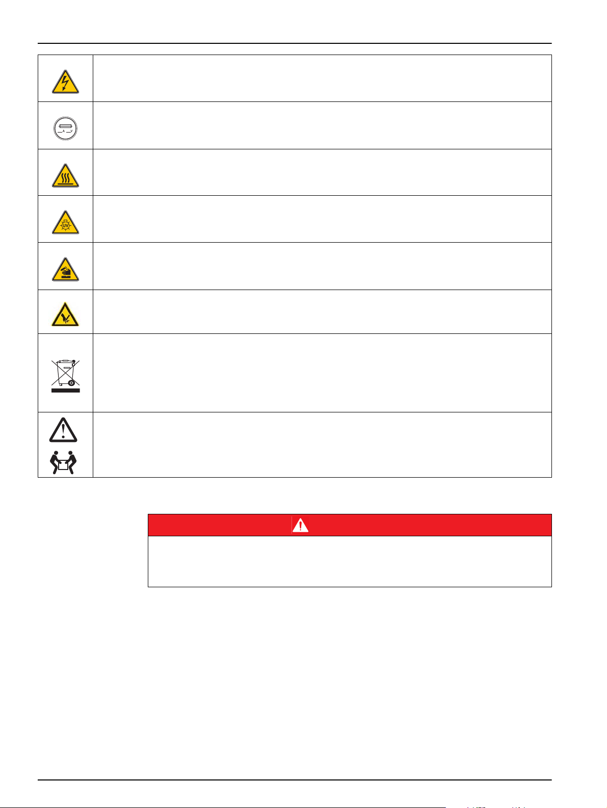
This symbol, if noted on the instrument, references the instruction manual for operation and/or safety
information.
7
Page 8
General information
18-32 kg (39.7-70.5 lbs
This symbol may be found on an enclosure or barrier within the product and indicates a risk of electric shock
and/or death by electrocution.
If shown on the device, this symbol indicates the location of a fuse or current limiter.
If shown on the device, this symbol indicates a component that can be hot and must not be touched without
precautionary measures.
This symbol indicates that a UV lamp is used in the device.
If shown on the device, this symbol indicates dangerous chemical substances. The handling of chemicals and
the execution of maintenance on chemical feed equipment of the device may only be carried out by qualified
personnel who are trained to work with chemicals.
If shown on the device, this symbol indicates dangerous places on the device that can result in crushing or
surface damage. Only operate the device with closed safety covers.
Electrical equipment marked with this symbol may no longer be disposed of in unsorted European domestic or
public disposal systems after 12 August 2005. In conformity with the applicable provisions, consumers in the
EU must return old electrical equipment to the manufacturer for disposal from this date. This is at no charge to
the user.
Note: Contact the manufacturer or supplier for instructions on how to return end-of-life devices,
manufacturer-supplied electrical accessories and all auxiliary items for pro per disposal.
When carrying or transporting the instrument components or instrument and if the total weight is more than
18 kg, make sure that suitable lifting equipment is used and/or that the instrument components or instrument
are/is carried by two people.
2.1.3 Chemical and biological safety
Potential danger with contact with chemical/biological substances.
Working with chemical samples, standards and reagents can be dangerous. Make yourself
familiar with the necessary safety procedures and the correct handling of the chemicals before
the work and read and follow all relevant safety data sheets.
Normal operation of this instrument may involve the use of hazardous chemicals or
biologically harmful samples.
• Before handling these substances observe all danger notes and safety information
printed on the containers of the original solutions and in the safety data sheet.
DANGER
• Dispose of all consumed solutions in accordance with the national regulations and
laws.
• Select the type of protective equipment accordingly
2.1.4 Safety around source lamps
The source lamps are operated at high temperatures.
8
Page 9
To avoid the risk of electrocution, make sure the instrument is disconnected from the
power source before changing the lamps.
Health hazard caused by ozone.
Hazardous levels of ozone can be generated when the UV lamp is not cooled.
Health risk due to UV light.
UV light can cause irritation to the eyes and skin. Protect eyes and skin from direct exposure to
UV light.
Do not look directly at an energized lamp without UV safety glasses.
Burn hazard. Allow the lamp(s) to cool for at least 30 minutes before maintaining/replacing them.
2.2 Product overview
General information
CAUTION
WARNING
CAUTION
The instrument may not be used in dangerous environments.
The manufacturer and its suppliers reject any express or indirect guarantee for use with high-risk
activities.
Any use other than use in accordance with requirements defined in the user manual leads to the
loss of the warranty claims and can lead to personal injury and property damage, for which the
manufacturer assumes no liability.
2.2.1 Product overview of the Ganimede P
In combination with the ready-to-use GaniChem P GCA 100 reagent kit, the Ganimede P
enables a rapid and automated serial analysis of PO
orthophosphate in accordance with DIN EN 1189 of December 1996.
The digestion of the total phosphate takes place as high-temperature digestion.
The phosphate content is determined as phosphorus molybdenum blue at 880 nm.
2.2.2 Product overview of the Ganimede N
In combination with the ready-to-use GaniChem N GCA 200 reagent kit, the Ganimede N
enables a quick and automated serial analysis of inorganically and organically bound
nitrogen in aqueous samples in accordance with DIN EN ISO 11 905-1.
WARNING
NOTICE
and PO4-P as total phosphate or
4
Inorganically and organically bound nitrogen is oxidized to nitrate with peroxodisulfate by
means of alkaline digestion at 150
The nitrate content is photometrically measured by means of UV self-absorption in a
differential measurement at 210
°C and 8 bar.
nm and 228 nm.
9
Page 10
General information
2.3 Scope of delivery
Please check that the order is complete. If anything is missing or damaged, please contact
the manufacturer or retailer.
• Sample changer
• Open-loop control unit
• Analysis unit P or analysis unit N
2.4 Front and rear view
2.4.1 Sample changer
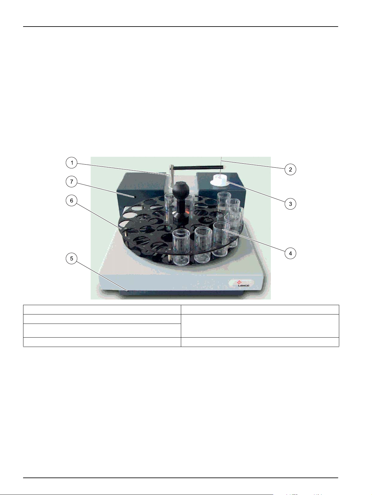
Figure 1 Front view of sample changer
1 Sample changer arm 5 Reset button
2 Sample needle 6 Sample tray (here, 36 positions for 30-mL sample
3 Rinsing vessel for sample needle
4 Sample containers 7 Light-emitting diode
10
containers; a sample tray with 53 positions for 18-mL
sample containers is optionally available)
Page 11
General information
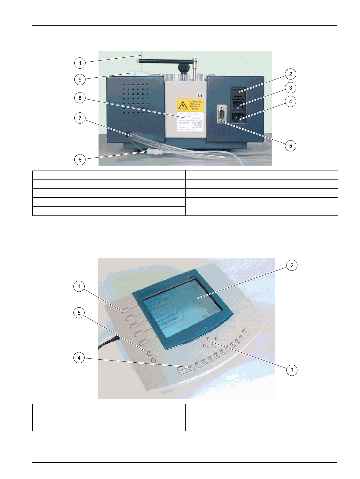
Figure 2 Rear view of sample changer
1 Sample needle 6 Suction tube for rinse water
2 Fuse (2× T 1.25 A L, 250 VAC) 7 Drain hose
3 Power switch 8 Type plate
4 Power connector 9 Rinsing vessel for sample needle
5 Interface for the analysis unit connection cable
2.4.2 Open-loop control unit
Figure 3 Front view of the open-loop control unit
1 Shortcut keys 4 Alphanumeric keys
2 Graphical display 5 Menu keys
3 Cursor keys
11
Page 12
General information
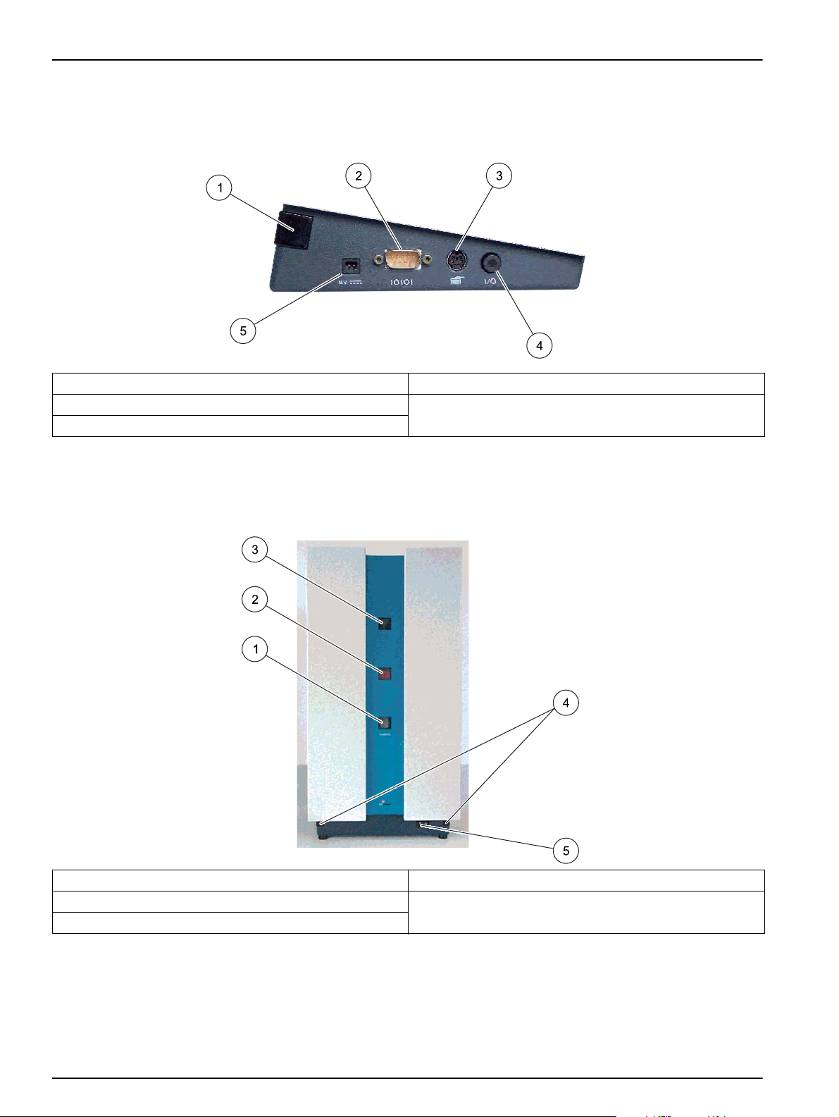
Figure 4 Detailed view of the open-loop control unit
1 IR interface 4 Power switch
2 RS 232 interface for PC and hand-held scanner 5 Power connector
3 Interface for compact keyboard
2.4.3 Analysis unit
Figure 5 Front view of analysis unit
1 Analysis cuvette monitoring window 4 IR interfaces
2 LCD display of the current sample 5 Power switch
3 Digestion cuvette monitoring window
12
Page 13
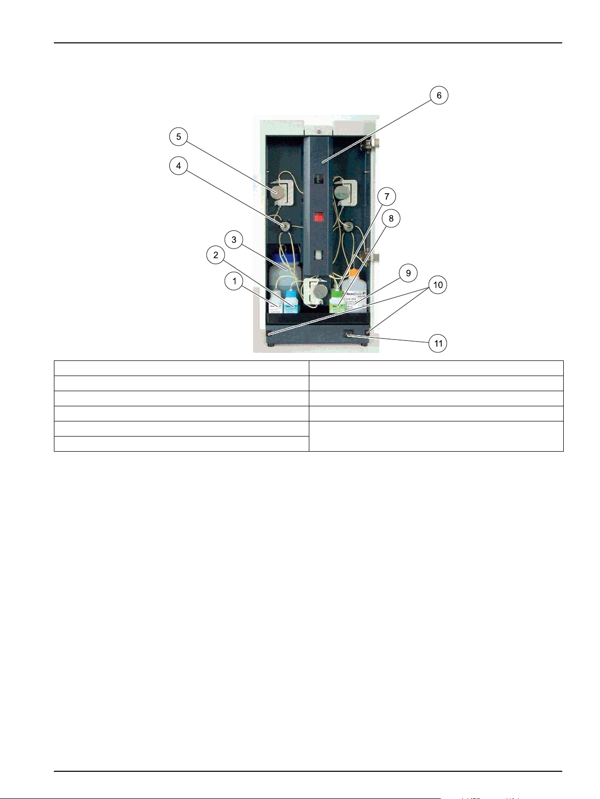
Figure 6 Interior view of analysis unit P
General information
1 Digestion solution A 7 Acid solution D
2 Color solution B 8 Reduction solution C
3 Waste bottle 9 Distilled water
4 Valve 10 IR interfaces
5 Pump 11 Power switch
6 Safety cover
13
Page 14
General information
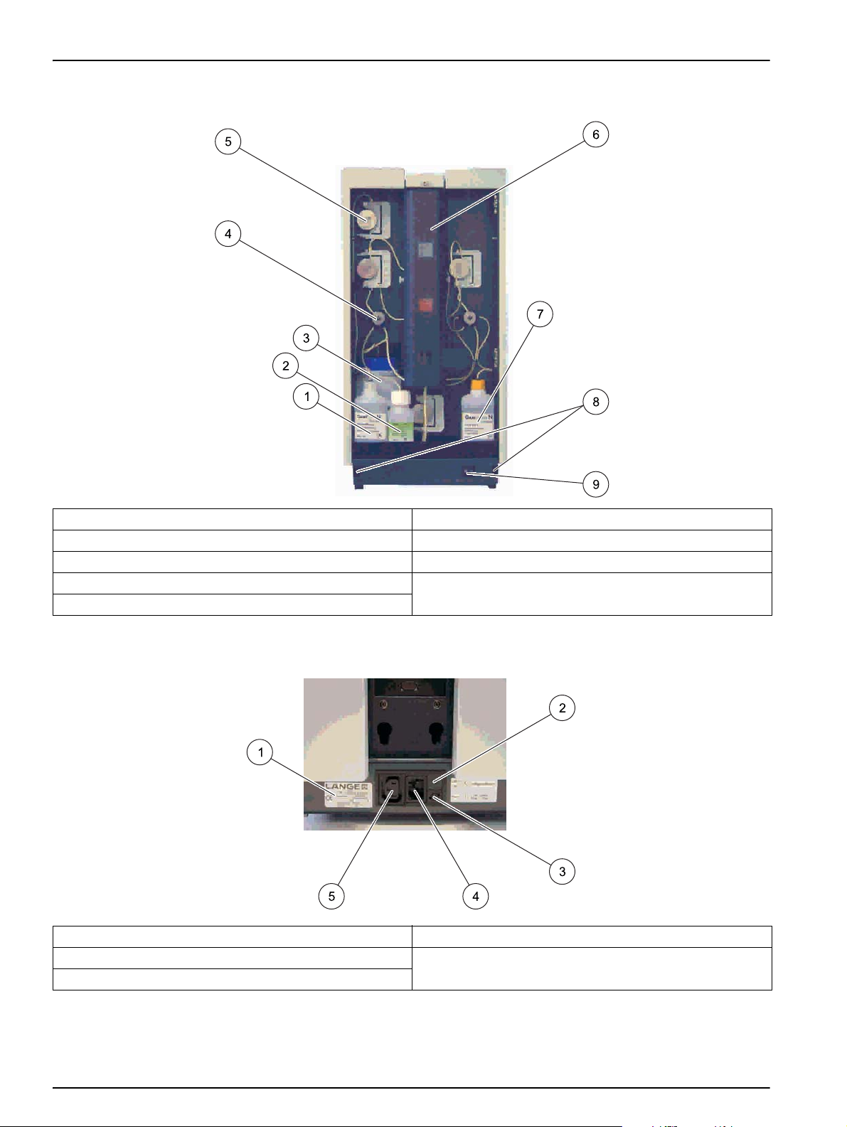
Figure 7 Interior view of analysis unit N
1 Acid solution A 6 Safety cover
2 Digestion solution B 7 Distilled water
3 Waste bottle 8 IR interfaces
4 Val ve 9 Power switch
5 Pump
Figure 8 Analysis unit power connector
1 Type plate 4 Power connector
2 230 V/115 V voltage selector switch 5 Sample changer power connector
3 T3A L fuse, 250 V
14
Page 15
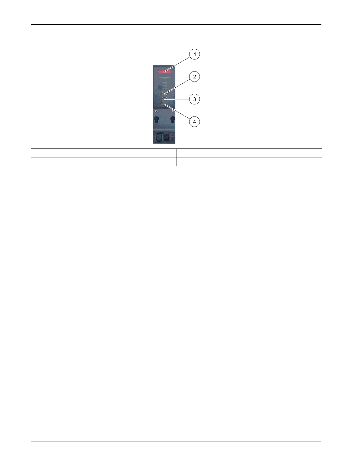
Figure 9 Analysis unit interfaces
1 Printer interface 3 RS 232 socket
2 Sample changer interface 4 RS 232 connector
General information
15
Page 16

General information
16
Page 17
Section 3 Installation
3.1 Installation of the components
The instrument may not be used in dangerous environments.
The manufacturer and its suppliers reject any express or indirect guarantee for use with high-risk
activities.
Any use other than use in accordance with requirements defined in the user manual leads to the
loss of the warranty claims and can lead to personal injury and property damage, for which the
manufacturer assumes no liability.
Unpack all supplied parts carefully, as they are highly sensitive in part to shock and
impact. Read the user manual prior to installation and proceed exactly as described.
3.1.1 Operating environment
Observe the following points to allow the instrument to function normally and give a long
operating life.
• Position the instrument securely on a flat surface taking care to remove any objects
from under the device.
WARNING
NOTICE
• The ambient temperature must be 15 °C to 35 °C (60 °F to 95 °F).
• The relative humidity must be lower than 75% (no condensate formation).
• A minimum clearance of 15 cm (5.9inches) must be ensured above and on all sides of
the device; this allows the air to circulate and prevents overheating of the electric
components. The dosage arm of the sample changer must be able to move freely.
• Do not operate or store the instrument in extremely dusty, humid or wet locations.
• Make sure that no liquids enter the instrument and immediately wipe away any liquids
that contact the instrument.
• Protect the instrument against vibrations, direct sunlight, corrosive gases as well as
strong magnetic and/or electric fields.
• Only use genuine replacement parts and accessories.
• The instrument must be serviced by the manufacturer's service department at the
prescribed intervals.
3.1.2 Installation of the devices
When carrying or transporting the instrument components or instrument and if the total weight is
more than 18 kg, make sure that suitable lifting equipment is used and/or that the instrument
components or instrument are/is carried by two people.
WARNING
The carrying strap provided must be used to be able to carry the analysis unit safely over
short distances.
17
Page 18
Installation
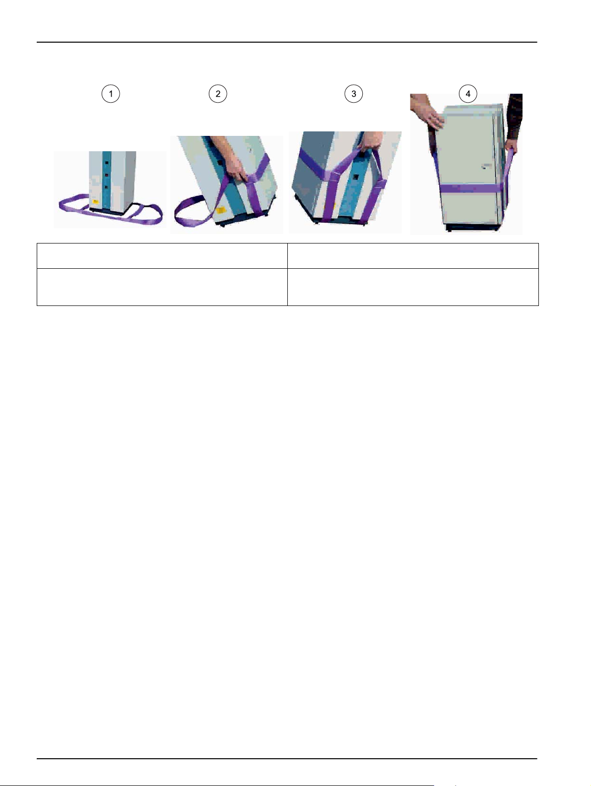
Figure 10 Use of the carrying strap
1 Slip the carrying strap over the analysis unit as shown in
the illustration.
2 Carefully tip the analysis unit to the side and guide the
outer parts of the carrying strap behind the feet of the
unit. Proceed in the same way on the opposite side.
1. Place the analysis unit on a stable and level tabletop. Level out any unevenness with
the rear adjustable feet.
2. Remove the transport locking screws on the bottom of the sample changer.
To do so, tip the sample changer to the side and remove the screws above the
corresponding sign.
3. Position the sample changer to the left of the analysis unit on a stable and level
tabletop.
4. Place the open-loop control unit near (approx. 0.5 m 1.64 ft) to the analysis unit.
Note: Communication between the analysis unit and the open-loop control unit takes place via
IR interfaces.
3 Tightly pull the carrying belt upwards at the front and
back sides.
4 The analysis unit must now be transported safely over a
short distance by two people.
18
Page 19

3.1.3 Installation of the cables
Danger of an electric shock.
Use only the supplied power cable.
If another power cable without a protective earth contact is used or if the sample changer is
connected to a mains connection without a ground connection, there is the danger of an electric
shock for the operator and of the destruction of the device.
Electrical and fire hazards.
Use only the supplied power cable.
Only qualified experts may perform the tasks described in this section of the manual, while
adhering to all locally valid safety regulations.
Removable power cables must not be replaced with inadequately dimensioned power cables.
Installation
DANGER
WARNING
WARNING
NOTICE
Use only an earthed socket for the connection of this device to the power supply.
If you are not sure if the socket is earthed, have this checked by a qualified electrician.
The power plug serves in addition to the power supply to isolate the device quickly from the
mains where necessary.
This is recommended when the instrument is not used for a long time, and can prevent potential
dangers in the event of a fault.
Therefore, make sure that socket to which the device is connected is easy to reach by each user
at all times.
1. Select the appropriate mains voltage (230 V or 115 V) for the region with the voltage
selector switch on the rear side of the analysis unit.
2. Connect the analysis unit to an earthed mains socket with the power cable (230 volts
+5 %/-15 %/50 Hz).
3. Optionally, connect a printer or PC to the corresponding interface of the analysis unit
4. Connect the SAMPLER interface of the analysis unit to the sample changer interface
with the connection cable (XLH917).
5. Connect the sample changer to the "sample changer power connector" on the
analysis unit with the power cable.
Note: Use only the supplied power cable.
6. Connect the external power supply unit of the open-loop control unit to an earthed
mains socket (230 volt +5 %/-15 %/50 Hz).
Note: Use only the external LZV563 power supply unit.
Note: The open-loop control unit is equipped for rechargeable battery operati on. The char ge
status is indicated permanently on the display. A red battery symbol indicates a weak
rechargeable battery. The battery symbol is shown in black when the rechargeable battery is
being charged. The fully charged rechargeable battery enables an operating time of
approximately 2.5 hours.
19
Page 20

Installation
7. Optionally, connect a hand-held scanner or a keyboard to the corresponding interface
of the open-loop control unit.
3.1.4 Installation of the tubes
Potential danger with contact with chemical/biological substances.
Working with chemical samples, standards and reagents can be dangerous. Make yourself
familiar with the necessary safety procedures and the correct handling of the chemicals before
the work and read and follow all relevant safety data sheets.
Risk of injury to the eyes, skin and respiratory tract
During work with chemicals and/or solvents, it is absolutely necessary to pay attention to the
relevant accident prevention regulations and to wear suitable personal protective equipment for
the eyes, face, hands and body, and/or respiratory protection.
Make sure that the system is only unpacked, assembled, connected and operated by qualified
and trained personnel.
Make sure that the waste container and the drain hose are always positioned lower than the
sample changer. The rinsing fluid must be able to flow unimpeded.
Make sure that the tubes are not kinked or jammed.
Check the capacity of the waste bottles constantly.
DANGER
WARNING
3.1.4.1 Installation of the tubes for the Ganimede P
1. Install all tubes of the analysis unit in accordance with Figure 11 Tube plan for
analysis unit P, page 22.
2. Screw the large blue lid onto the empty waste bottle (1500 mL).
Note: The waste bottle can take the reagent and sample waste from 100 individual
determinations.
3. Connect reagents GCA 100 with the corresponding lids of the same color.
4. Install sample tube A.
To do so, lead the free end of sample tube A out through the left-hand side of the
analysis unit housing.
Connect the upper end of the sample needle with sample tube A.
5. Insert the sample needle into the guide of the sample changer arm.
Note: The sample needle must not reach the bottom of the sample container when magnetic
rods are used.
6. Install the suction tube for the rinse water of the sample needle.
To do so, connect the end with a screw thread to the permanently mounted tube on
the rear side of the sample changer.
Insert the free end of the suction tube into a bottle of distilled water.
Note: It is essential that the needle rinser is connected in order to make sure that a sample
batch drains faultlessly. Sufficient rinse water (distilled water) must be available at all times.
20
Page 21

Installation
7. Install the drain hose.
Attach one end of the suction tube to the white tube connection on the rear side of
the sample changer.
Insert the free end of the drain hose into a suitable waste container.
Note: The waste container and the drain hose must always be positioned lower than the sample
changer. The rinsing fluid must be able to drain unimpeded; the drain hose must not be kinked!
Check the capacity of the waste bottle.
21
Page 22

Installation
Figure 11 Tube plan for analysis unit P
1 Pump 1 10 Reaction solution C
2 Digestion cuvette 11 Pump 4
3 Overpressure discharge 12 Analysis cuvette
4 Pump 3 13 Waste bottle
5 Pump 3 14 Color solution B
6 Air intake 15 Digestion solution A
7 Val ve 2 16 Valve 1
8 Distilled water 17 Sample tube 1 sample feed coming from the sample
9 Acid solution D
changer
22
Page 23

Identification
Color in tube
plan
Table 1 Tube overview for analysis unit P
Length
Dia-
meter
Colored
adapter
Installation
Connected:
A: (included in
the scope of
delivery of the
sample
changer)
B Red 140 mm 2.67 mm -
C Pink 380 mm 3.04 mm Yellow/blue
D Gray 300 mm 3.04 mm -
E Green 530 mm 3.2 mm Yellow/blue
F Blue 450 mm 3.2 mm -
G Green 300 mm 3.04 mm -
H Orange 180 mm 3.04 mm -
J Black 550 mm 3.53 mm
K Purple 500 mm 4.17 mm
L Black 300 mm 3.04 mm -
Black 400 mm 2.67 mm -
Gray/green/g
reen
Gray/black/p
urple
Sample changer sample needle
-> Left-hand side of the analysis unit housing
-> Valve 1 connection f
Valve 1 connection b
-> Left-hand analysis cuvette
Valve 1 connection g
-> Pump 1
-> Digestion cuvette
Digestion solution A
-> Valve 1 connection d
Right-hand analysis cuvette
-> Pump 2
-> Valve 2 connection g
Color solution B
-> Valve 2 connection e
Reduction solution C
-> Valve 2 connection c
Distilled water
-> Valve 2 connection b
Analysis cuvette
-> Pump 3
Lower analysis cuvette
-> Pump 4
-> T-piece -\> Valve 1 connection c
and -\> Waste bottle
Acid solution D
-> Valve 2 connection d
3.1.4.2 Installation of the tubes for the Ganimede N
1. Install all tubes of the analysis unit in accordance with Figure 12 Tube plan for
analysis unit N, page 25.
2. Screw the large blue lid onto the empty waste bottle (1500 mL).
Note: The waste bottle can take the reagent and sample waste from 100 individual
determinations.
3. Connect the GCA 200 reagents with the corresponding lids of the same color.
4. Install sample tube A.
To do so, lead the free end of sample tube A out through the left-hand side of the
analysis unit housing.
Connect the upper end of the sample needle with sample tube A.
5. Insert the sample needle into the guide of the sample changer arm.
Note: The sample needle must not reach the bottom of the sample container when magnetic
rods are used.
23
Page 24

Installation
6. Install the suction tube for the rinse water of the sample needle.
To do so, connect the end with a screw thread to the permanently mounted tube on
the rear side of the sample changer.
Insert the free end of the suction tube into a bottle of distilled water.
Note: It is essential that the needle rinser is connected in order to make sure that a sample
batch drains faultlessly. Sufficient rinse water (distilled water) must be available at all times.
7. Install the drain hose.
Attach one end of the suction tube to the white tube connection on the rear side of
the sample changer.
Place the free end of the drain hose in a suitable waste container.
Note: The waste container and the drain hose must always be positioned lower than the sample
changer. The rinsing fluid must be able to drain unimpeded; the drain hose must not be kinked!
Check the capacity of the waste bottle.
24
Page 25

Figure 12 Tube plan for analysis unit N
Installation
1 Tube routing 9 Distilled water
2 Pump 1 10 Pump 4
3 Pump 3 11 Analysis cuvette
4 Digestion cuvette 12 Waste bottle
5 Overpressure discharge 13 Digestion solution B
6 Pump 3 14 Acid solution A
7 Valve 2 15 Valve 1
8 O-ring for tube routing 16 Sample tube 1 sample feed coming from the sample
changer
25
Page 26

Installation
Identification
Color in tube
plan
Table 2 Tube overview for analysis unit N
Length
Dia-
meter
Colored
adapter
Connected:
A: (included in
the scope of
delivery of the
sample
changer)
B Black 950 mm 3.2 mm Yellow/blue
C Purple 380 mm 3.2 mm Blue/yellow
D Red 215 mm 2.7 mm Blue/yellow
E Green 550 mm 3.2 mm Gray
F Purple 230 mm 3.5 mm -
G Red 220 mm 3.0 mm -
H Orange 220 mm 3.0 mm -
J Blue 250 mm 3.0 mm
Gray 400 mm 2.67 mm -
Black/purple/
gray
Sample changer sample needle
-> Left-hand side of the analysis unit housing
-> Valve 1 connection f
Acid solution A
-> Pump 3
-> Left-hand analysis cuvette
Valve 1 connection g
-> Pump 1
-> Digestion cuvette
Digestion cuvette
-\> Valve 2 connection d
Valve 2 connection g
-> Pump 2
-> Right-hand analysis cuvette
Valve 2 connection e
-> Lower right-hand analysis cuvette (air)
Digestion solution B
-> Valve 1 connection d
Distilled water
-> Valve 2 connection b
Valve 2 connection c
-> T-piece -\> Pump 4 -\> Lower analysis
cuvette
-> T-piece -\> Waste bottle
-> Valve 1 connection c
3.1.5 Installation of the sample tray
Possible risk of injury due to the sample needle.
Make sure that the system is only installed by qualified and trained personnel.
The position designations for the sample containers are printed next to the sampling
openings.
1. Make sure that the sample changer is switched off.
2. Load the sample containers with at least 15 mL of homogenized samples and zero or
standard solution. Add magnetic rods if necessary.
3. Place the filled sample containers on the sample tray without interruption, starting
with position 1.
4. Place the sample tray on the spindle of the sample changer from above.
5. Turn the sample tray until it locks.
6. Switch on the sample changer.
WARNING
26
Page 27

7. The sample tray is subsequently turned automatically to the correct position and the
sample needle dips into the rinsing solution.
Note: A sample stray for 53 samples of 15 mL each is available for special applications.
The reset button on the front left-hand side of the housing is used for initialization of the
sample changer. The reset button must not be actuated during a sample series.
The green light-emitting diode on the front left-hand side of the housing indicates that the
sample changer is in operation.
3.2 Open-loop control unit
3.2.1 Overview of the display and keys of the open-loop control unit
Figure 13 Overview of the display and keys
Installation
1 Menu keys 4 Display and input area
2 Shortcut keys 5 Cursor keys
3 Menu selection 6 Alphanumeric keys
Error messages
Error messages are shown in red on the display. Press the top menu key in order to be
able to continue to work.
Exit the menu
Press the top menu key.
Edit selection lists
Selection with the cursor keys. Press the enter key to confirm the selection.
Alphanumeric keys
Numbers, letters and special characters can be entered with the alphanumeric keys.
27
Page 28

Installation
Table 3 Assignment of the alphanumeric keys
Key abc ABC
1 _ 1 . : , ( ) % 1 ? _ 1 . : , ( ) % 1 ?
2 ABC a b c 2 ä à á â ã å æ ç A B C 2 Ä À Á Ã Å Æ Ç
3 DEF d e f 3 è é ê D E F È É
4 GHI g h i 4 G H I 4
5 JKL j k l 5 J K L 5
6 MNO m n o 6 ö ò ó ô õ Ø œ ñ m n o 6 ö ò ó õ Ø ñ
7 PQRS p q r s 7 ß P Q R S 7
8 TUV t u v 8 ü ù ú û t u v 8 ü ù ú û
9 WXYZ w x y z 9 W X Y Z 9
0 + + - 0 / \* + - 0 / \ *
3.2.2 Switch-on of the open-loop control unit
The open-loop control unit is switched on with the power switch on the left-hand side of the
housing.
The open-loop control unit is ready for operation after the manufacture's logo is shown.
The charge status of the battery, as well as the date and time, are shown on the display
next to the main menu.
Upon delivery, the open-loop control unit is set to the correct national language, date and
time. If these values are not entirely correct, they can be changed in the menu option
OPTIONS, DATE/TIME and OPTIONS, LANGUAGE.
The main menu options are accessed with the adjacent shortcut keys.
3.3 Reagents
3.3.1 Reagents for Ganimede P
The GCA 100 reagents for the automated orthophosphate and total phosphate
determination are designed for 100 determinations. The principle of the reaction complies
with DIN EN 1189 of December 1996.
Phosphate ions react in acid solution with molybdate and antimony ions to form an
antimony–phosphomolybdate complex that is reduced to phosphorus molybdenum blue
by means of ascorbic acid.
The opened solutions can be kept for seven days at room temperature.
Prepare the reagents according to the work instructions enclosed in the reagent
packaging.
28
NOTICE
The Ganimede P and the ready-to-use GaniChem-P GCA 100 reagent kit are optimally adapted
for each another. The use of third-party chemicals can result in the impairment of the results and
the whole system.
The guarantee claim only remains valid with the use of GaniChem-P GCA 100.
Page 29

3.3.2 Reagents for Ganimede N
The GCA 200 reagents for the automated sum determination of inorganically and
organically bound nitrogen are each designed for 100 determinations.
Inorganically and organically bound nitrogen is oxidized to nitrate with peroxodisulfate by
means of an alkaline digestion. The nitrate content is photometrically measured by means
of UV self-absorption in a differential measurement at 210
The opened solutions can be kept for seven days at room temperature.
Prepare the reagents according to the work instructions enclosed in the reagent
packaging.
The analysis unit N and the ready-to-use GaniChem-N GCA 200 reagent kit are adapted
optimally for each another. The use of third-party chemicals can result in the impairment of the
results and the whole system.
The guarantee claim only remains valid with the use of GaniChem-N GCA 200.
3.3.3 Storage
The original substances are stored at room temperature. The fully prepared solutions are
stored in the refrigerator for brief storage (e.g. over a weekend).
Installation
nm and 228 nm.
NOTICE
The reagents remain in the analysis unit when the Ganimede is used daily.
3.3.4 Reagents reserve
A package of GCA 100 for Ganimede P or GCA 200 for Ganimede N is designed for
100
single analyses, and appropriate pre-rinsing amounts for 4–5 analysis series are
included per package. The maximum number of determinations can be reduced from 100
in the event of a higher number of analysis series per package.
A waste bottle can hold the reagent waste and sample waste of one package (i.e. 100
single determinations).
The exact reagent reserves of the chemicals can be shown by means of the menu items
OPTIONS, REAGENT STATUS.
3.4 Ganimede P sample preparation
• Samples must lie within the pH range 2–10.
• Samples that contain substances that react aggressively with Viton, e.g. solvents,
must be diluted.
• Samples containing particulates must be homogenized with a disintegrator for 30
seconds.
• Homogenized samples in positions 1 to 27 can be stirred with magnetic rods with the
sample tray for 36 sample containers.
• The sample containers are suitable for one-time use only. Residues of cleaning
agents can lead to increased phosphate findings.
3.4.1 Load the sample tray
Each sample tray is a sample batch.
If multi-point calibration is to be used, a standard curve with 2–11 measurement points
must be recorded before the measurement series. The device refers to this recorded
curve during measurement operation.
29
Page 30

Installation
Alternatively, it is possible to work with a two-point calibration. In addition, a zero standard
solution, or alternatively two standard solutions, is/are positioned in positions 35 and 36.
To do so, load the sample tray as follows:
• According to the sample batch, the sample tray is loaded with the samples from
position 1.
• For a two-point calibration, the standards are positioned with the measurement series
on a sample tray for 36 sample containers as follows:
Position 35: GCZ 100 zero solution
Position 36: standard, e.g. 0.2 mg/L PO
-P GCS 050
4
Alternatively:
Position 35: 1st standard, e.g. 0.2 mg/L PO
Position 36: 2nd standard, e.g. 2 mg/L PO
-P GCS 050
4
-P GCS 100
4
Single and double determinations can be carried out. For double determinations, the
sample is drawn from a container twice. The settings refer to the whole sample tray.
Two sample containers must be filled with the sample if the orthophosphate and total
phosphate content is to be determined from a sample. The allocation of the determination
method (orthophosphate or total P) to the position numbers of the sample containers is
performed during definition of the sample batch with the open-loop control unit. If
necessary, the use of the sample tray for 53 sample containers is recommended.
The following table and illustration show an example of a sample tray load for a two-point
calibration:
Table 4 Sample tray load for 36 sample containers, Ganimede P
Position Load
35 GCZ 100 zero solution
36 GCS 050 standard solution
1 Sample 1 orthophosphate
2 Sample 1 total phosphate
3 Sample 2 orthophosphate
4 Sample 2 total phosphate
5 Sample 3 orthophosphate
6 Sample 3 total phosphate
7 Sample 4 orthophosphate
8 etc. Sample 4 total phosphate, etc.
30
Page 31

Figure 14 Example of a sample tray load, Ganimede P
Installation
1 Zero solution 3 Samples
2 Standard solution 4 Empty positions
3.5 Ganimede N sample preparation
• Samples that contain substances that react aggressively with Viton, e.g. solvents,
must be diluted.
• Samples containing particulates must be homogenized with a disintegrator for 30
seconds.
• Homogenized samples in positions 1 to 27 can be stirred with magnetic rods with the
sample tray for 36 sample containers.
• The sample containers are suitable for one-time use only.
3.5.1 Load the sample tray
Each sample tray is a sample batch.
If multi-point calibration is to be used, a standard curve with 2–11 measurement points
must be recorded before the measurement series. The device refers to this recorded
curve during measurement operation.
Alternatively, it is possible to work with a two-point calibration. To do so, two standard
solutions are each positioned in positions 33 and 36 for the low and high measurement
range.
For this, load the sample tray as follows:
• According to the sample batch, the sample tray is loaded with the samples from
position 1.
31
Page 32

Installation
• For a two-point calibration, the standards are positioned with the measurement series
on a sample tray for 36 sample containers as follows:
Position 33: 1st low standard, e.g. 0.5 mg/L TN
Position 34: 2nd low standard, e.g. 30 mg/L TN
Position 35: 1st high standard, e.g. 30 mg/L TN
Position 36: 2nd high standard, e.g. 100 mg/L TN
The low standards can be selected freely in the range 0.5–30 mg/L TN
standards can be selected freely in the range 30–150 mg/L TN
GCZ 100
B
GCS 050
B
GCS 050
B
GCS 100
B
; the high
B
.
B
Single and double determinations can be carried out. For double determinations, the
sample is drawn from a container twice. The settings refer to the whole sample tray.
The following table and illustration show an example of a sample tray load for a two-point
calibration:
Table 5 Sample tray load for 36 sample containers, Ganimede N
Position Load
33 1st low standard, e.g. 0.5 mg/L TN
34 2nd low standard, e.g. 30 mg/L TN
35 1st high standard, e.g. 30 mg/L TN
36 2nd high standard, e.g. 100 mg/L TN
1 Sample 1
2 Sample 2
3 Sample 3
4 Sample 4
5 Sample 5
6 etc. Sample 6 etc.
GCZ 100
B
GCS 050
B
GCS 050
B
GCS 100
B
32
Page 33

Figure 15 Example of a sample tray load, Ganimede P
Installation
1 Low-range standard solution 3 Samples
2 High-range standard solution 4 Empty positions
33
Page 34

Installation
34
Page 35

Section 4 Operation
4.1 Operation of the open-loop control unit
The sample batch is defined with the open-loop control unit according to:
• Parameter (phosphate with Ganimede P or nitrogen with Ganimede N)
• Number of samples
• Single or double determination
• Orthophosphate or total phosphate determination with Ganimede P
or low or high measurement range with Ganimede N
• Analysis as PO
• Dilution factor
• User etc.
Defined sample batches can be saved and retrieved again, modified or copied at any time.
Thus, a new definition of repeated sample batches is omitted.
A two-point calibration, or alternatively a multi-point calibration, can be used in
measurement operation.
For a multi-point calibration, a standard curve must be recorded before the measurement
series. At least five standards are prescribed according to DIN. Optionally, an individual
standard curve is also possible with 2–11 measurement points. The device refers to this
recorded curve during measurement operation if desired.
Alternatively, a two-point calibration can be used during a measurement series with
Ganimede P. To do so, a zero solution (GCZ 100) and a standard are positioned in
positions 35 and 36, or alternatively two different standard solutions.
With Ganimede N, a two-point calibration is used by positioning two standard solutions for
the low and high measurement ranges in each position from 33 to 36.
The operation of the open-loop control unit is carried out via an external keypad or via the
alphanumeric keys of the open-loop control unit. The color graphical display shows the
operation of the different menu levels. Error messages, erroneous entries and abnormal
measurements are presented in color.
, PO4-P or P2O5 with Ganimede P
4
The communication of the open-loop control unit and the analysis unit takes place via the
IR interface. In order to enable a connection, the open-loop control unit must be brought
near (approximately 0.5
data that defines the sample batch is sent. The measurement procedure is started
automatically and the connection is disconnected.
The analysis unit saves all raw data during the measurement. This data can be retrieved
by the open-loop control unit at any time during or after the measurement. For this, the
connection via the IR interface is established again, the measurement results are
transmitted and displayed as a table in the open-loop control unit.
If the sample batch is processed completely and all data is sent, the connection is
disconnected automatically. The measurement results can be displayed, edited and sent
to the PC, printer and LIMS by means of the open-loop control unit.
meters) to the analysis unit. A connection is established, then the
35
Page 36

Operation
4.2 Menu structure of the open-loop control unit
4.2.1 Menu structure
Analysis
Samples
Display of a list of all saved sample batches (maximum 30) for the various
Analysis X batch Y
Calibrate Save measured standard curves
Phosphorus Phosphate parameters for Ganimede P
Standard curve 1 Storage location for standard curve 1 with 2 to 11 measurement points
Add Add standard
Remove Remove standard
Graph Show standard series as a graph
Measure Measure standard absorbance
User Input of the username
Standard curve 2
Standard curve 3
Nitrogen Nitrogen parameters for Ganimede N
Standard curve 1 Storage location for standard curve 1 with 2 to 11 measurement points
low
Add Add standard
Remove Remove standard
Graph Show standard series as a graph
Measure Measure standard absorbance
Users Input of the username
high
Add Add standard
Remove Remove standard
Graph Show standard series as a graph
Measure Measure standard absorbance
Users Input of the username
Standard curve 2
Standard curve 3
Rinse A rinse of the system must be run for longer downtime and after every workday.
Stop
parameters (phosphate or nitrogen).
Selection of the desired batch starts the measuring procedure
Storage location for standard curve 2 with 2 to 11 measurement points, all submenus
the same as standard curve 1
Storage location for standard curve 3 with 2 to 11 measurement points, all submenus
the same as standard curve 1
Storage location for standard curve 1 in the low measurement range with 2 to 11
measurement points
Storage location for standard curve 1 in the high measurement range with 2 to 11
measurement points
Storage location for standard curve 2 with 2 to 11 measurement points, all submenus
the same as standard curve 1
Storage location for standard curve 3 with 2 to 11 measurement points, all submenus
the same as standard curve 1
Interrupts the analysis series, e.g. in the event of damage, errors occurring or
incorrect load
36
Page 37

4.2.1 Menu structure
Edit
Program Create and save a new sample batch
Phosphorus Definition of a sample batch for phosphorus
Name Name, maximum 20 characters long, for the sample batch e.g. Well 1-10
Users
Measurements Single or double determination
Calibration
Sample data Opens an input window for the description of individual samples.
Position Automatic numbering (1–36)
Sample Sample name, maximum 13 characters long
Method Total phosphate or orthophosphate
Express as PO
Unit Selection of the unit mg/L, g/L, µg/L, mmol/L, mg/100 g or Ext.
Control standard
Dilution The selection of a dilution factor against which the result is to be offset
Factor Freely definable specific sample factor (0.001 – 9999)
Sampling Date and time of sampling
Note Note regarding the sample, maximum 30 characters long
Nitrogen Definition of a sample batch for nitrogen
Name Name, maximum 20 characters long, for the sample batch e.g. Well 1-10
User
Measurements Single or double determination
Calibration
Sample data Opens an input window for the description of individual samples.
Position Automatic numbering (1–36)
Sample Sample name, maximum 13 characters long
Method Low measurement range (0.5–30 mg/L TN
Express as TN
Unit Selection of the unit mg/L, g/L, µg/L, mmol/L, mg/100 g or Ext.
Control standard
Dilution The selection of a dilution factor against which the result is to be offset
Factor Freely definable specific sample factor (0.001 – 9999)
Sampling Date and time of sampling
Note Note regarding the sample, maximum 30 characters long
Name of the user. The usernames must be defined beforehand under the menu
option EDIT, USER.
Two-point calibration with two selectable standard concentrations or
Multi-point calibration with access to standard curve 1, 2 or 3 (the standard curve
must first be recorded under the menu option ANALYSIS, CALIBRATION)
, PO4-P or P2O
4
A control standard with freely selectable concentration and permissible deviation can
also be measured on the sample tray.
Control standard selection YES or NO.
Name of the user. The usernames must be defined beforehand under the menu
option EDIT, USER.
Two-point calibration with two selectable standard concentrations in the low and high
measurement range respectively or
Multi-point calibration with access to standard curve 1, 2 or 3 (the standard curve
must first be recorded under the menu item ANALYSIS, CALIBRATION)
A control standard with freely selectable concentration and permissible deviation can
also be measured on the sample tray.
Control standard selection YES or NO.
5
) or high (30–150 mg/L TNB)
B
Operation
37
Page 38

Operation
4.2.1 Menu structure
Modify Saved sample batches can be modified.
Modify Selection list of all saved sample batches. Select the desired sample batch.
Name Name, maximum 20 characters long, for the sample batch e.g. Well 1-10
User
Measurements Single or double determination
Calibration
Sample data Opens an input window for the description of individual samples.
Position Automatic numbering (1–36)
Sample Sample name, maximum 13 characters long
Method
Express as
Unit Unit selection mg/L, g/L, µg/L, mmol/L, mg/100 g or Ext.
Control standard
Dilution The selection of a dilution factor against which the result is to be offset
Factor Freely definable specific sample factor (0.001 – 9999)
Sampling Date and time of sampling
Note Note regarding the sample, maximum 30 characters long
Erase The saved sample batch can be erased
Erase Selection list of all saved sample batches. Select the desired sample batch.
Copy The saved sample batch can be saved under a new name.
Copy Selection list of all saved sample batches. Select the desired sample batch.
Users Up to 19 usernames with maximum 10 characters.
New Definition of a new username
Erase Deletion of a username
Dilution
New Definition of a new dilution stage
Erase Deletion of a dilution stage
Name of the user. The usernames must be defined beforehand under the menu
option EDIT, USER.
Two-point calibration with two selectable standard concentrations or
Multi-point calibration with access to standard curve 1, 2 or 3 (the standard curve
must be recorded under the menu option ANALYSIS, CALIBRATION)
Total phosphate or orthophosphate and/or
low measurement range (0.5–30 mg/L TN
, PO4-P or P2O5 or
PO
4
TN
A control standard with freely selectable concentration and permissible deviation can
also be measured on the sample tray.
Control standard selection YES or NO.
Display of nine predefined dilution stages that can be changed individually. A further
11 dilution stages can be saved.
) or high (30–150 mg/L TNB)
B
38
Page 39

4.2.1 Menu structure
Data
After a connection to the analysis unit has been established, a list of current
measurement results is shown.
In addition to the mean value, both single results and single absorbances are
Current
Express as The sample name can be changed.
Unit The unit mg/L, g/L, µg/L, mmol/L, mg/100 g or Ext. can be changed.
Dilution If the dilution factor is changed, the result is calculated again automatically.
Factor If the sample-specific factor is changed, the result is calculated again automatically.
Sampling The date and time of the sampling can be changed
Note The comment on the sample, a maximum of 30 characters long, can be changed
Display Display of all saved measurement results for the individual sample batches.
Data/display Selection list of all saved sample batches. Select the desired sample batch.
Output
PC
Printers
LIMS
displayed for a double determination. Measurement results that are beyond the
selected measurement range are shown in red.
Note: A new measurement can be started only if the results of the previous
measurement are transferred completely to the open-loop control unit and the
indicator display of the analysis unit is no longer flashing.
Output of the saved measurement results of the different sample batches to the PC,
printer or a LIMS system.
Transfer of the measurement results to the PC via the RS 232 interface of the
open-loop control unit.
Transfer of the measurement results to the analysis unit by means of the IR interface
and then on to the printer via the RS 232 interface of the analysis unit.
Transfer of the measurement results to the analysis unit by means of the IR interface
and then on to the LIMS system via the RS 232 interface of the analysis unit.
Operation
39
Page 40

Operation
4.2.1 Menu structure
Options
About Display of the program version, control files and operating hours
Reagent status Display of the reagent quantity and the range
Reagent status
Reagent status 100
Date/time Input of date and time for the open-loop control unit.
Display contrast Set the display contrast.
Lighter
Darker
Interfaces Configuration of the interfaces for PC/scanner and LIMS system
PC/scanner
Scanner
XON / XOFF
9600 Baud rate
None Parity
LIMS
9600 Baud rate
None Parity
Printers Display of the connected printers on the open-loop control unit and analysis unit
Language Selection list of available languages
Display of the number of samples that can be analyzed with the remaining reagent
quantity.
Reset of the sample counter after the analysis unit has been loaded with a new
reagent kit.
4.2.2 Start of a measurement series
1. Load the sample tray according to the sample batch with the samples starting from
position 1.
Note: The data is overwritten if a sample batch is already stored. A copy must be created
beforehand if the data is to be retained.
2. If a multi-point calibration is selected for the calibration of the measurement series,
the device refers to one of the three saved calibration curves.
For Ganimede P, the following applies:
The standards are placed on the sample tray with the measurement series as follows
for a two-point calibration:
• Position 35: zero solution, GCZ 100
• Position 36: standard, e.g. 0.2 mg/L PO
Alternatively:
• Position 35: 1st standard, e.g. 0.2 mg/L PO
• Position 36: 2nd standard, e.g. 2 mg/L PO
For Ganimede N, the following applies:
The standards are placed on the sample tray with the measurement series as follows
for a two-point calibration:
• Position 33: 1st low standard, e.g. 0.5 mg/L TN
• Position 34: 2nd low standard, e.g. 30 mg/L TN
• Position 35: 1st high standard, e.g. 30 mg/L TN
-P GCS 050
4
-P GCS 050
4
-P GCS 100
4
GCZ 100
B
GCS 050
B
GCS 050
B
40
Page 41

• Position 36: 2nd high standard, e.g. 100 mg/L TNB GCS 100
Operation
The low standards can be selected freely in the range 0.5–30 mg/L TN
standards can be selected freely in the range 30–150 mg/L TN
3. Place the sample tray on the sample changer.
4. Switch on the analysis unit and the sample changer.
5. Select the desired sample batch with the cursor keys and the enter key.
A connection to the analysis unit is established automatically via the IR interface
(maximum distance 0.5 meters).
6. Select the desired parameter (phosphorus or nitrogen).
The measuring procedure is started.
Note: The open-loop control unit must not be moved or removed during the transmission
procedure. The whole data transfer is shown on the display.
The open-loop control unit/analysis unit connection is disconnected automatically.
7. Close the window with the upper menu key.
4.2.3 Calibration (recording of multi-point calibrations)
4.2.3.1 Ganimede P
In the storage locations for STD. CURVE 1, 2 and 3, standard curves with 2 to 11
measurement points are measured and stored. The device refers to these stored curves if
the sample batch is to be processed after the multi-point calibration.
; the high
B
.
B
1. Select standard curves 1, 2 or 3.
The selected standard curve is opened; standard curves that have already been
stored can be modified individually.
2. Select the standard concentration to be changed and confirm the input.
3. Enter the standard concentration with the alphanumeric keys or the connected
keypad and confirm the input.
4. Add further standard measurement points or remove points with the shortcut keys.
5. Open the standard series graphically with the GRAPH shortcut key.
The standard curve can be printed out with Enter.
6. Measure the standard absorbances with the MEASURE shortcut key.
7. Load the sample changer with the desired standard solutions in ascending order from
position 1.
The standard solutions GCS 050 and GCS 100 with 0.2 mg/L and 2 mg/L PO
-P and
4
their dilutions are recommended.
8. Make the analysis unit ready for operation.
9. Switch on the analysis unit and the sample changer.
10. Start the measurements of the standard solutions with the MEASURE shortcut key.
A connection to the analysis unit is established automatically via the IR interface.
11. Select the phosphorus parameter.
The measuring process is started.
Note: The open-loop control unit must not be moved or removed during the transmission
procedure. The whole data transfer is shown on the display.
41
Page 42

Operation
4.2.3.2 Ganimede N
12. Confirm the input with the top menu key and close the window.
In the storage locations for STD. CURVE 1, 2 and 3, standard curves, with 2 to 11
measurement points each in the low and high measurement range, are measured and
stored. The device refers to these stored curves if the sample batch is to be processed
after the multi-point calibration.
1. Select standard curves 1, 2 or 3 and the low or high measurement range.
The selected standard curve is opened; standard curves that are already stored can
be modified individually.
2. Select the standard concentration to be changed and confirm the input.
3. Enter the standard concentration with the alphanumeric keys or the connected
keypad and confirm the input.
4. Add further standard measurement points or remove points with the shortcut keys.
5. Open the standard series graphically with the GRAPH shortcut key.
The standard curve can be printed out with Enter.
6. Measure the standard absorbances with the MEASURE shortcut key.
4.2.4 Rinse
7. Load the sample changer with the desired standard solutions in ascending order from
position 1.
The standard solutions GCZ 100, GCS 050 and GCS 100 with 0.5 mg/L, 30 mg/L and
100 mg/L TN
and their dilutions are recommended.
B
8. Make the analysis unit ready for operation.
9. Switch on the analysis unit and the sample changer.
10. Start the measurements of the standard solutions with the MEASURE shortcut key.
A connection to the analysis unit is established automatically via the IR interface.
11. Select the nitrogen parameter.
The measuring process is started.
Note: The open-loop control unit must not be moved or removed during the transmission
procedure. The whole data transfer is shown on the display.
12. Confirm the input with the top menu key and close the window.
Note: If only one measurement range (high or low) is stored under the standard curve 1, 2 or 3, only
samples of the corresponding measurement range can be measured with this standard curve.
Combinations of different standard curves (e.g. standard curve 1 low and st andard curve 2 high) are
not possible.
42
A rinse of the system with cleaning solution (GCR 100 for Ganimede P and GCR 200 for
Ganimede N) is necessary every working day.
1. Remove the reagent bottles and close the bottles tightly with the corresponding
color-marked lids.
2. Store reagents in the refrigerator.
Note: The reagents can be kept for a maximum of seven days after opening.
3. Connect the bottles with cleaning solutions to the corresponding lid under
consideration of the color markings.
Page 43

4.2.5 Stop
Operation
4. Check the capacity of the waste bottle.
5. Start the rinse procedure with the RINSE shortcut key.
6. Switch on the prepared analysis unit.
7. Confirm the safety prompt.
A connection to the analysis unit is established automatically via the IR interface.
8. Select the desired parameter.
The rinse process is started. The rinsing of the analysis unit is finished after two
minutes and the system can be switched off.
In the event of damage, an error or an incorrect load, the analysis series can be
interrupted immediately with the STOP shortcut key. A connection to the analysis unit is
established automatically via the IR interface.
1. Select and confirm the desired parameter.
The measurement series is interrupted.
2. Close the window with the upper menu key.
If the error or damage cannot be fixed without switching off the analysis unit, proceed as
follows:
4.2.6 Data/current
3. Replace the reagent bottles with the cleaning solutions and activate RINSE.
4. Connect the reagent bottles with the analysis unit again for further analyses.
5. Load the sample tray.
6. Define the sample batch.
7. Start with ANALYZE.
After the connection has been established, a list of the latest current measurement results
is shown with the Data/CURRENT menu option. In addition to the mean value, both single
results and single absorbances are displayed for a double determination. Measurement
results that are beyond the selected measurement range are shown in red.
1. Select DATA and CURRENT.
A connection to the analysis unit is established.
2. Select the desired parameter.
The list of current results opens.
3. Select the result to be edited with the cursor keys and confirm with the enter key.
The measurement results can now be edited.
The sample name, the unit, the indication of the result, e.g. as PO
the sample collection time and the note can be changed.
If the dilution factor or the sample-specific factor is changed, the result is calculated
again automatically.
The position, result, method and measurement time components cannot be changed
afterwards.
, PO4-P or P2O5,
4
4. Select CALIBRATION DATA in order to display the calibration that was carried out.
43
Page 44

Operation
The input is carried out via the alphanumeric keys of the open-loop control unit or via a
connected compact keyboard.
Note: A new measurement can be started only if the results of the previous measurement are
transferred completely to the open-loop control unit and the indicator display of the analysis unit is
no longer flashing.
44
Page 45

Section 5 Maintenance
5.1 Sample changer
The sample changer must be disconnected from the mains during cleaning. The PTFE sealing
rings in the housing on the sample arm, on the rinsing vessel and the sealing ring on the tray
holder must not be removed!
Further repairs can only be carried out by the manufacturer's service departments.
The sample changer is a maintenance-free device. For safe and accurate operation, it is
necessary to keep the device clean. A soft cloth that is moistened with water should be
used for (external) cleaning. It must be made sure that no fluid penetrates the device
during cleaning!
In the event of an overflow of the rinsing vessel or spillage of small amounts of liquid over
the sample changer, the sample changer must be switched off (the power plug must then
be disconnected!) and cleaned (in order to dry it). If larger quantities of liquid enter into the
device, it must be made sure that the device is dried completely before switching it back
on.
5.2 Open-loop control unit
DANGER
The open-loop control unit is cleaned with a soft cloth that is moistened with water.
Further repairs can only be carried out by the manufacturer's service departments.
5.3 Analysis unit
Under no circumstances may the digestion cuvette and its supply and drainage lines be opened
or manipulated.
If an over-pressure is intercepted by the dual protection system, the analysis unit must be
switched off and the service department must be informed in order to avert damage to the device.
Burn hazard
Only remove the cover with the power plug pulled out and with a cooling time of a few minutes.
All defects that cannot be repaired by means of a tube change or by means of cleaning the
analysis cuvette, may only be repaired by the service personnel authorized by the
manufacturer.
For the cleaning of the cuvette and for the tube change, it is necessary to remove the
cover in the middle of the device with the lateral knurled screws.
DANGER
DANGER
5.3.1 Mount the cover
1. Hook the cover onto the upper housing edge.
2. Guide the tubes into the recesses on the right and left.
3. Press on the cover.
4. Make sure that no tube is jammed.
5. Fasten the cover with the knurled screws.
45
Page 46

Maintenance
5.3.2 Downtime
In the event of downtime, e.g. overnight or over weekends, a rinse of the system with
cleaning solution (GCR 100) must be carried out.
1. In each case, remove a reagent bottle and seal it with the original lid of the same
color.
The opened reagents are stored in the refrigerator.
Note: The opened reagents can be kept for a maximum of seven days at room temperature.
2. Connect the bottles with cleaning solutions to the corresponding lids.
3. Check the capacity of the waste bottle.
4. Start the rinse process with the open-loop control unit.
The process is finished after four minutes and the system can be switched off.
In the switched-off state, all tubes should be disconnected from the pump-tube clamps to
slacken them, in order to guarantee the intended service life.
1. Press the nose of the clamp downward (1) and to the right (2).
The clamp swivels downward (3) and is held in the holder (4).
The tube is now slackened.
For start-up, the tubes must be tensioned in the tube clamps again.
2. Swivel the clamp upward.
3. Press the nose downward and the clamp to the left.
Figure 16 Slacken a tube in a pump
1 Press the nose downward. 3 Swivel the clamp downward.
2 Press the clamp to the right. 4 The clamp is held in the metal holder.
5.3.3 Tube change
A change of the whole tube set is necessary every three months. The tubes become
porous due to the thermal and mechanical load.
5.3.3.1 Insertion of the tube in a pump
1. Place the tube with the colored tabs in the groove above and below the clamp (1).
46
Page 47

2. Mount the clamp in the metal holder (2) from below. In so doing, tilt the clamp forward
slightly.
3. Swivel the clamp upward (3).
4. Press the nose downward (4) and the clamp to the left (5).
Note: It is recommended to change one tube at a time in order to prevent mix-ups, i.e. each
removed tube is immediately replaced with the corresponding new tube.
Figure 17 Insertion of the tube in a pump
Maintenance
1 Place the tube with the colored tabs in the groove above
and below the clamp.
2 Mount the clamp in the metal holder from below. 5 Press the clamp to the left.
3 Swivel the clamp upward.
4 Press the nose downward.
5.3.4 Clean the analysis cuvette
DANGER
Potential hazards (e.g. cut injuries) due to mechanical damage of the analysis cuvette (breakage
of glass).
Wear protective clothing, protective gloves and safety glasses/face protection that are suitable for
the work being performed.
The analysis cuvette is cleaned every three months or as required.
1. Disconnect the power plug and wait a few minutes until the digestion cuvette has
cooled down.
2. Remove the protective cover with the knurled screws.
3. Carefully pull the two tubes out of the lower part of the analysis cuvette according to
Figure 18 and Figure 19.
4. Remove the tubes from the analysis cuvette.
5. Loosen the plastic screw on the right-hand side of the cuvette slightly with a
screwdriver.
6. Loosen the connection pieces for the tubes with two screws and remove them
upward from the cuvette.
7. Carefully remove the cuvette forward.
Note: Make sure not to damage the photometer unit.
47
Page 48

Maintenance
8. Clean the cuvette with a moist cotton bud from inside.
9. If necessary, use a suitable cleaning solution, e.g. Extran for Ganimede P, alcohol for
Ganimede N (ethanol, propanol).
Note: Do not use any cleaning agents that could contain detergents on the Ganimede N.
10. Rinse the cuvette with distilled water or allow the cleaning agent to evaporate fully.
11. Ganimede P:
Insert the cleaned cuvette and pull the cuvette downward completely.
Ganimede N:
Insert the cleaned cuvette so that the guide rail on the left-hand side of the cuvette is
flush with the upper edge of the optical window.
12. Attach the cuvette carefully with the plastic screws.
13. Attach the connection pieces with the screws.
14. Connect all tubes according to Figure 18 or Figure 19.
Figure 18 Cleaning of the Ganimede P analysis cuvette
Tube B Tube J
Tube E Tube K
48
Page 49

Figure 19 Cleaning of the Ganimede N analysis cuvette
Tube B Tube F
Tube E Tube J
5.3.5 Cleaning of the analysis unit
Maintenance
The housing is cleaned with a soft, possibly damp, cloth. The reagent chamber can be
cleaned with a damp cloth. The collecting tray can be removed for cleaning.
49
Page 50

Maintenance
50
Page 51

Section 6 Troubleshooting
6.1 Error messages on the open-loop control unit
Error message Note
Notice:
The transferred data XXXXX could not be assigned!
XXXXX= sample batch name
Sample batch was not accepted
Notice:
Reagents are no longer sufficient for the intended
measurements.
Continue? ENTER: Yes Esc: No
Establishing connection. Please wait!
The connection is interrupted!
6.2 Error messages on the analysis unit
The measurement results saved in the analysis unit could not
be assigned to a sample batch in the open-loop control unit.
The sample batch was probably deleted or the sample batch
name was modified in the open-loop control unit.
There are still measurement results in the analysis unit that
have not yet been retrieved with DATA, CURRENT.
Load the analysis unit with a new set of chemical reagents
and set the reagent status to 100.
Switch on the analysis unit. Move the open-loop control unit
near (0.5 m) to the front of the analysis unit.
The infrared connection has been disconnected. Move the
control unit near (0,5 m) to the front of the analysis unit.
Error message Meaning Solution
2–4 Internal analysis unit error Consult service technician
5 No contact to the sample changer
6 Sample changer mechanical error Insert the sample tray again, consult a service technician
7 Photo signal faulty Clean the analysis cuvette, consult a service technician
Switch on the sample changer, check the sample
changer/analysis unit connection cable (connector)
51
Page 52

Troubleshooting
52
Page 53

Section 7 Replacement parts and accessories
7.1 Replacement parts
Description Cat. No
Sample changer including sample tray for 36 sample containers, 25 mL each LQV 134
Sample tray for 36 sample containers, 25 mL each LZQ 031
Sample tray for 53 sample containers, 15 mL LZQ 032
15-mL polystyrene sample containers, 100 pieces (for aqueous solutions, acids and bases) LZQ 034
25-mL polystyrene sample containers, 100 pieces (for aqueous solutions, acids and bases) LZQ 035
Drain hose for sample changer LZQ 039
Suction tube for sample changer LZQ 038
Complete tube set for the sample changer, including needle LZV 263
Open-loop control unit LPV 135
Complete tube set for Ganimede P analysis unit LZV 262
Ganimede P analysis cuvette HBK 057
Complete tube set for Ganimede N analysis unit LZV 423
Ganimede N analysis cuvette HBK 059
Sample changer –·analysis unit connection cable XLH 917
Sample changer – analysis unit power cable XLH 060
External power supply, 15 VDC/2 A LZV 563
1.5-m cable for the open-loop control unit/PC connection LZV 087
Analysis unit power cable YAA 080
Analysis unit – PC connection cable XLH 917
7.2 Accessories
Description Cat. No
GaniChem P, reagent kit for automatic phosphate analytics, measurement range 0.01 –
3.8 mg/L (PO
-P), 100 determinations
4
Zero solution 250 mL GCZ 100
Standard solution 250 mL, 2 mg/L PO4-P GCS 100
Standard solution 250 mL, 0.2 mg/L PO
-P GCS 050
4
Calibration solutions
Standard 1: 0 mg/L PO
Standard 2: 0.5 mg/L PO
Standard 3: 1.0 mg/L PPO
Standard 4: 2.0 mg/L PO
Standard 5: 3.8 mg/L PO
-P for GaniChem P, 100 mL
4
-P for GaniChem P, 100 mL
4
-P for GaniChem P, 100 mL
4
-P for GaniChem P, 100 mL
4
-P for GaniChem P, 100 mL
4
Cleaning solution for Ganimede P GCR 100
GaniChem N, reagent kit for the automatic determination of inorganically and organically bound
nitrogen, measurement range 0.5 – 150 mg/L TNB, 100 determinations
Standard solution 250 mL, 0.5 mg/L TN
Standard solution 250 mL, 30 mg/L TN
Standard solution 250 mL, 100 mg/L TN
B
B
B
Calibration solutions 0.5 – 30 mg/L TNB,
Standard 1: 3 mg/L TN
Standard 2: 9 mg/L TN
Standard 3: 15 mg/L TN
for GaniChem N, 100 mL
B
for GaniChem N, 100 mL
B
for GaniChem N, 100 mL
B
Standard 4: 21 mg/L TNB for GaniChem N, 100 mL
Standard 5: 27 mg/L TN
for GaniChem N, 100 mL
B
GCA 100
GCS 200
GCA 200
GCS 025
GCZ 100
GCS 100
GCS 300
53
Page 54

Replacement parts and accessories
7.2 Accessories
Description Cat. No
Calibration solutions 30 – 150 mg/L TNB,
Standard 1: 30 mg/L TNB for GaniChem N, 100 mL
Standard 2: 60 mg/L TN
Standard 3: 90 mg/L TN
Standard 4: 120 mg/L TNB for GaniChem N, 100 mL
Standard 5: 150 mg/L TN
Cleaning solution for Ganimede N GCR 200
Magnetic rods, 10 pieces LZQ 045
Compact keypad LZV 260
GaniTrans software including 1.5 m connection cable LZV 404
for GaniChem N, 100 mL
B
for GaniChem N, 100 mL
B
for GaniChem N, 100 mL
B
GCS 350
54
Page 55

Section 8 Contact information
HACH Company
World Headquarters
P.O. Box 389
Loveland, Colorado
80539-0389 U.S.A.
Tel (800) 227-HACH
(800) -227-4224
(U.S.A. only)
Fax (970) 669-2932
orders@hach.com
www.hach.com
HACH LANGE GMBH
Willstätterstraße 11
D-40549 Düsseldorf
Tel. +49 (0)2 11 52 88-320
Fax +49 (0)2 11 52 88-210
info@hach-lange.de
www.hach-lange.de
HACH LANGE GMBH
Rorschacherstrasse 30a
CH-9424 Rheineck
Tel. +41 (0)848 55 66 99
Fax +41 (0)71 886 91 66
info@hach-lange.ch
www.hach-lange.ch
Repair Service in the
United States:
HACH Company
Ames Service
100 Dayton Avenue
Ames, Iowa 50010
Tel (800) 227-4224
(U.S.A. only)
Fax (515) 232-3835
HACH LANGE LTD
Pacific Way
Salford
GB-Manchester, M50 1DL
Tel. +44 (0)161 872 14 87
Fax +44 (0)161 848 73 24
info@hach-lange.co.uk
www.hach-lange.co.uk
HACH LANGE FRANCE
S.A.S.
8, mail Barthélémy Thimonnier
Lognes
F-77437 Marne-La-Vallée
cedex 2
Tél. +33 (0) 820 20 14 14
Fax +33 (0)1 69 67 34 99
info@hach-lange.fr
www.hach-lange.fr
Repair Service in Canada:
Hach Sales & Service
Canada Ltd.
1313 Border Street, Unit 34
Winnipeg, Manitoba
R3H 0X4
Tel (800) 665-7635
(Canada only)
Tel (204) 632-5598
Fax (204) 694-5134
canada@hach.com
HACH LANGE LTD
Unit 1, Chestnut Road
Western Industrial Estate
IRL-Dublin 12
Tel. +353(0)1 460 2522
Fax +353(0)1 450 9337
info@hach-lange.ie
www.hach-lange.ie
HACH LANGE NV/SA
Motstraat 54
B-2800 Mechelen
Tel. +32 (0)15 42 35 00
Fax +32 (0)15 41 61 20
info@hach-lange.be
www.hach-lange.be
Repair Service in
Latin America, the
Caribbean, the Far East,
Indian Subcontinent, Africa,
Europe, or the Middle East:
Hach Company World
Headquarters,
P.O. Box 389
Loveland, Colorado,
80539-0389 U.S.A.
Tel +001 (970) 669-3050
Fax +001 (970) 669-2932
intl@hach.com
HACH LANGE GMBH
Hütteldorfer Str. 299/Top 6
A-1140 Wien
Tel. +43 (0)1 912 16 92
Fax +43 (0)1 912 16 92-99
info@hach-lange.at
www.hach-lange.at
DR. LANGE NEDERLAND
B.V.
Laan van Westroijen 2a
NL-4003 AZ Tiel
Tel. +31(0)344 63 11 30
Fax +31(0)344 63 11 50
info@hach-lange.nl
www.hach-lange.nl
HACH LANGE APS
Åkandevej 21
DK-2700 Brønshøj
Tel. +45 36 77 29 11
Fax +45 36 77 49 11
info@hach-lange.dk
www.hach-lange.dk
HACH LANGE LDA
Av. do Forte nº8
Fracção M
P-2790-072 Carnaxide
Tel. +351 214 253 420
Fax +351 214 253 429
info@hach-lange.pt
www.hach-lange.pt
HACH LANGE KFT.
Vöröskereszt utca. 8-10.
H-1222 Budapest XXII. ker.
Tel. +36 1 225 7783
Fax +36 1 225 7784
info@hach-lange.hu
www.hach-lange.hu
HACH LANGE AB
Vinthundsvägen 159A
SE-128 62 Sköndal
Tel. +46 (0)8 7 98 05 00
Fax +46 (0)8 7 98 05 30
info@hach-lange.se
www.hach-lange.se
HACH LANGE SP. ZO.O.
ul. Krakowska 119
PL-50-428 Wrocław
Tel. +48 801 022 442
Zamówienia: +48 717 177 707
Doradztwo: +48 717 177 777
Fax +48 717 177 778
info@hach-lange.pl
www.hach-lange.pl
HACH LANGE S.R.L.
Str. Că
minului nr. 3,
et. 1, ap. 1, Sector 2
RO-021741 Bucureşti
Tel. +40 (0) 21 205 30 03
Fax +40 (0) 21 205 30 17
info@hach-lange.ro
www.hach-lange.ro
HACH LANGE S.R.L.
Via Rossini, 1/A
I-20020 Lainate (MI)
Tel. +39 02 93 575 400
Fax +39 02 93 575 401
info@hach-lange.it
www.hach-lange.it
HACH LANGE S.R.O.
Zastrčená 1278/8
CZ-141 00 Praha 4 - Chodov
Tel. +420 272 12 45 45
Fax +420 272 12 45 46
info@hach-lange.cz
www.hach-lange.cz
HACH LANGE
8, Kr. Sarafov str.
BG-1164 Sofia
Te l.
+359 (0)2 963 44 54
Fax +359 (0)2 866 15 26
info@hach-lange.bg
www.hach-lange.bg
HACH LANGE S.L.U.
Edificio Seminario
C/Larrauri, 1C- 2ª Pl.
E-48160 Derio/Vizcaya
Tel. +34 94 657 33 88
Fax +34 94 657 33 97
info@hach-lange.es
www.hach-lange.es
HACH LANGE S.R.O.
Roľnícka 21
SK-831 07 Bratislava –
Vaj nory
Tel. +421 (0)2 4820 9091
Fax +421 (0)2 4820 9093
info@hach-lange.sk
www.hach-lange.sk
HACH LANGE SU
ANALİZ SİSTEMLERİ
LTD.ŞTİ.
Ilkbahar mah. Galip Erdem
Cad. 616 Sok. No:9
TR-Oran-Çankaya/ANKARA
Tel. +90312 490 83 00
Fax +90312 491 99 03
bilgi@hach-lange.com.tr
www.hach-lange.com.tr
55
Page 56

Contact information
HACH LANGE D.O.O.
Fajfarjeva 15
SI-1230 Domžale
Tel. +386 (0)59 051 000
Fax +386 (0)59 051 010
info@hach-lange.si
www.hach-lange.si
HACH LANGE OOO
Finlyandsky prospekt, 4A
Business Zentrum “Petrovsky
fort”, R.803
RU-194044, Sankt-Petersburg
Tel. +7 (812) 458 56 00
Fax. +7 (812) 458 56 00
info.russia@hach-lange.com
www.hach-lange.com
ΗΑCH LANGE E.Π.Ε.
Αυλίδος 27
GR-115 27 Αθήνα
Τηλ . +30 210 7777038
Fax +30 210 7777976
info@hach-lange.gr
www.hach-lange.gr
HACH LANGE D.O.O.
Ivana Severa bb
HR-42 000 Varaždin
Tel. +385 (0) 42 305 086
Fax +385 (0) 42 305 087
info@hach-lange.hr
www.hach-lange.hr
HACH LANGE MAROC
SARLAU
Villa 14 – Rue 2 Casa
Plaisance
Quartier Racine Extension
MA-Casablanca 20000
Tél. +212 (0)522 97 95 75
Fax +212 (0)522 36 89 34
info-maroc@hach-lange.com
www.hach-lange.ma
56
Page 57

Section 9 Warranty and liability
The manufacturer warrants that the product supplied is free of material and manufacturing
defects and undertakes the obligation to repair or replace any defective parts at zero cost.
The warranty period for instruments is 24 months. If a service contract is taken out within
6
months of purchase, the warranty period is extended to 60 months.
With the exclusion of further claims, the supplier is liable for defects including the lack of
assured properties as follows: All those parts that, within the warranty period calculated
from the day of the transfer of risk, can be demonstrated to have become unusable or that
can only be used with significant limitations due to a situation present prior to the transfer
of risk, in particular due to incorrect design, poor materials or inadequate finish will be
improved or replaced, at the supplier's discretion. At the discretion of the supplier, these
deficiencies will be corrected or the instrument replaced. The identification of such defects
must be notified to the supplier in writing without delay, however at the latest seven days
after the identification of the fault. If the customer fails to notify the supplier, the product is
considered approved despite the defect. Further liability for any direct or indirect damages
is not accepted.
If equipment-specific maintenance and servicing work defined by the supplier is to be
performed within the warranty period by the customer (maintenance) or by the supplier
(servicing) and these requirements are not carried out, claims for damages are rendered
void due to the failure to comply with the requirements.
Any further claims, in particular claims for consequential damages, cannot be made.
Consumables and damage caused by imcorrect handling, unsafe assembly or by incorrect
use are excluded from this provision.
The instruments of the manufacturer are of proven reliability in many applications and are
therefore often used in automatic control loops to provide the most economical possible
operation of the related process.
To avoid or limit consequential damage, it is therefore recommended to design the control
loop such that a malfunction in an instrument results in an automatic change over to the
backup control system, which is the most secure operating condition for the environment
and for the process
57
Page 58

Warranty and liability
58
Page 59

Appendix A Interface protocol
RS 232 interface for the analysis unit and open-loop control unit.
The RS 232 C interface has a 9-pole sub-D socket and a 9-pole sub-D connector. The
interface is connected to the serial interface (COM) of the computer (LIMS system) with
the PC cable (XLH 917).
Table 6 RS 232 I/O card connection assignment
9-pole SUB-D Socket 9-pole SUB-D Connector
PIN PIN
GND 5 GND 5
RxD 3 RxD 2
TxD 2 TxD 3
RTS8 RTS7
CTS 7 CTS 8
Table 7 RS 232 software description
ID Description
ID001 Start of a block
ID101 Parameters
ID102 Name
ID103 Users
ID104 Measurements (single/double)
ID107 Calibration (two-point/e.g. standard curve 1)
ID108 Sample tray measurement data
ID110 Method 0 name (total/low)
ID111 Standard absorbance 2 (two-point calibration)
ID112 Standard concentration 2 (two-point calibration)
ID114 Standard curve linear equation
ID115 Standard curve measurement data
ID116 Standard absorbance 1 (two-point calibration)
ID117 Standard concentration 2 (two-point calibration)
ID118 Standard curve lowest concentration
ID119 Standard curve highest concentration
ID120 Method name 1 (ortho/high)
ID121 Standard absorbance 2 (two-point calibration)
ID122 Standard concentration 2 (two-point calibration)
ID124 Standard curve linear equation
ID125 Standard curve measurement data
ID126 Standard absorbance 1 (two-point calibration)
ID127 Standard concentration 2 (two-point calibration)
ID128 Standard curve lowest concentration
ID129 Standard curve highest concentration
ID130 Start of a sample
ID131 Position
ID132 Sample name
59
Page 60

Interface protocol
Table 7 RS 232 software description
ID Description
ID133 Calculated concentration result 1
ID134 Absorbance 1
ID135 Unit
ID136 Express as
ID137 Method
ID138 Dilution
ID139 Factor
ID140 Sampling time
ID141 Sample collection date
ID142 Sample collection time
ID143 Comment
ID144 Calculated concentration result 2
ID145 Absorbance 2
ID146 Calculated concentration mean value
ID149 End of a sample
ID150 Concentration of the control standard
ID151 Permissible deviation (%)
ID152 Measured deviation result 1 (%)
ID153 Measured deviation result 2 (%)
ID154 Measured deviation mean value (%)
ID155 Result table
\qID999 \qEnd of a block
60
 Loading...