

Page 1
DOC023.52.90161
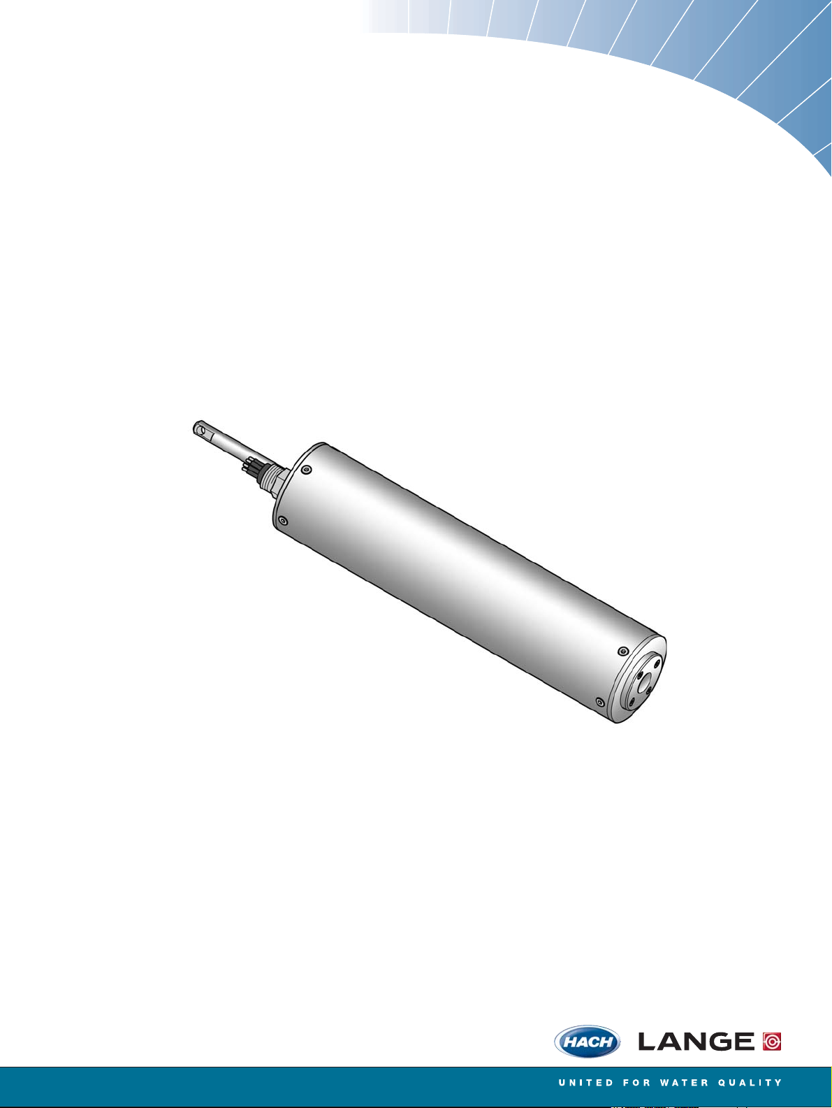
FP 360 sc
User Manual
01/2010, Edition 1B
© HACH-LANGE GmbH, 2010. All rights reserved. Printed in Germany
Page 2

Page 3

Table of Contents
Section 1 Specifications ........................................................................................................................ 5
1.1 Dimensions ........................................................................................................................................ 6
Section 2 General information............................................................................................................... 7
2.1 Safety information............................................................................................................................... 7
2.1.1 Use of hazard information.......................................................................................................... 7
2.1.2 Precautionary labels .................................................................................................................. 7
2.2 Product overview ................................................................................................................................ 8
2.3 Measuring principle............................................................................................................................. 8
2.4 Product components........................................................................................................................... 8
2.4.1 FP 360 sc sensor ...................................................................................................................... 9
2.5 Function test ....................................................................................................................................... 9
Section 3 Installation............................................................................................................................ 11
3.1 Connect sensor cable....................................................................................................................... 11
3.2 Installation options............................................................................................................................ 13
3.2.1 Installation with the chain mount kit ......................................................................................... 13
3.2.2 Installation of chain mount kit for sensors with cleaning unit ................................................... 13
3.2.2.1 Install the cleaning unit hose........................................................................................... 13
3.2.3 Installation with flow cell........................................................................................................... 15
Section 4 Operation.............................................................................................................................. 17
4.1 User interface and navigation ........................................................................................................... 17
4.2 Sensor setup..................................................................................................................................... 17
4.3 Sensor data logger ........................................................................................................................... 17
4.4 Menu structure.................................................................................................................................. 18
4.4.1 SENSOR STATUS................................................................................................................... 18
4.4.2 SENSOR SETUP..................................................................................................................... 18
4.5 Calibration......................................................................................................................................... 20
4.5.1 Factory calibration.................................................................................................................... 20
4.5.2 Process calibration/adjustment................................................................................................ 20
4.5.2.1 Determination of factors and adjustment of slope........................................................... 20
4.5.2.2 Multi-point calibration ...................................................................................................... 21
4.5.3 Check the zero point................................................................................................................ 21
4.5.4 Adjustment of slope and zero point; multi-point calibration......................................................21
4.5.4.1 Adjust the slope (FACTOR) ............................................................................................ 21
4.5.4.2 Adjust the zero point (OFFSET)...................................................................................... 22
4.5.4.3 Multi-point calibration (2 to 5-point calibration) ............................................................... 22
Section 5 Maintenance ......................................................................................................................... 23
5.1 Maintenance schedule...................................................................................................................... 23
5.2 Maintenance for the connectors on the sensor................................................................................. 23
5.3 Cleaning the measurement windows................................................................................................ 24
3
Page 4

Table of Contents
Section 6 Troubleshooting ...................................................................................................................25
6.1 Error messages.................................................................................................................................25
6.2 Warnings ...........................................................................................................................................25
6.3 Replacement parts ............................................................................................................................25
Section 7 Replacement parts and accessories ..............................................................................27
7.1 Sensor options ..................................................................................................................................27
7.2 Replacement parts ............................................................................................................................27
7.3 Accessories.......................................................................................................................................27
Section 8 Contact information ............................................................................................................29
Section 9 Warranty and Liability..........................................................................................................31
Appendix A Modbus register ..............................................................................................................33
Index.......................................................................................................................................................35
4
Page 5
Section 1 Specifications
Specifications are subject to change without notice.
Measurement
UV fluorescent measurement process for polycyclic aromatic
Measurement method
Low measurement range
Measuring range
High measurement range
Display units ppb, ppm, μg/L, mg/L
Reproducibility 2.5% of measurement value at a constant temperature
Measurement accuracy
Limit of detection 1.2 ppb (PAH)
Hydrocarbons (PAH)
Excitation wavelength: 254 nm
Emission (measurement) wavelength: 360 nm
0 to 50 ppb and 0 to 500 ppb in relation to PAH calibration standard,
corresponding to 0.1 to 1.5 ppm and 0.1 to 15 ppm of oil calibration
standard
0 to 500 ppb and 0 to 5000 ppb in relation to PAH calibration standard,
corresponding to 0.1 to 15 ppm and 0.1 to 150 ppm of oil calibration
standard
5% of measurement value ±2% from measurement range limit
at a constant temperature
Response time 10 s (T90)
Calibration
Sensor software
Software version From 1.14
Equipment properties
Measurement sensor Stainless steel version 2.8 kg, titanium version 1.8 kg
Weight
Flow cell Approximately 0.6 kg, including installation board approximately 2.0 kg
Sensor Max. 30 bar
Pressure range
Flow cell Max. 1 bar
Measurement sensor
(Ø × length)
Dimensions
Flow cell (L × W × D)
Measurement sensor
Materials
Flow cell
Shackle Stainless steel 1.4301
Factory calibration with UV fluorescence calibration standard, custom
adaptation possible
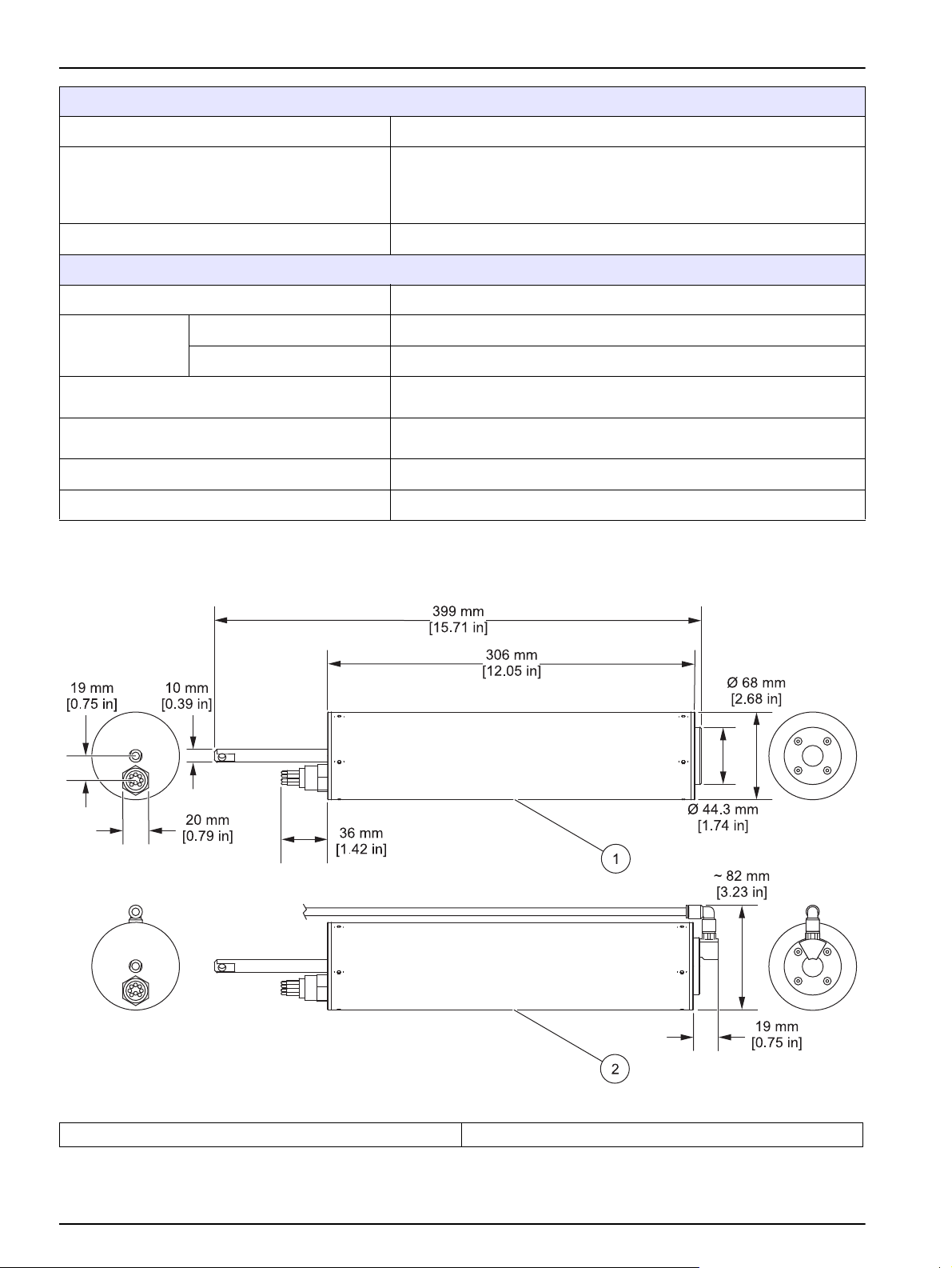
68 mm x 306 mm (2.68 in. x 12.05 in.)
(without plugs or suspension pin)
68 mm x 399 mm (2.68 in. x 15.71 in.) (including suspension pin)
68 mm x 413 mm (2.68 in. x 16.26 in.)
(with additional cleaning option)
98 mm x 98 mm x 150 mm (3.86 in. x 3.86 in. x 5.91 in.) (without
fittings),
installation board: 600 x 300 x 10 mm (23.62 in. x 11.81 in. x 0.39 in.)
Housing: stainless steel 1.4571 or titanium
Optic bracket: POM
Housing bolts: stainless steel 1.4571
Measurement window: synthetic quartz glass (Suprasil)
Gaskets (housing): Viton
Gaskets (measurement window): NBR (Nitrile Butadiene Rubber)
Housing: POM
Installation board: PVC
Gaskets: NBR (Nitrile Butadiene Rubber)
Fittings: nickel-plated brass
5
Page 6
Specifications
Environment considerations
Sample temperature 1 to 40 °C (34 to 104 °F)
–5 to +45 °C (23 to 113 °F)
Ambient temperature
Sensor distance - wall/ground min. 100 mm (3.94 in.) (recommended)
Miscellaneous
Cable length 1.5 or 10 m, extension cable up to total maximum length of 40 m
Measurement sensor wetted by at least half from the measuring
medium:
–25 to +55 °C (-13 to 131 °F)
Connection
information
Inspection interval
Maintenance requirements
Compliance CE
Warranty 2 years
Sensor side 8-pin, type of protection IP68, PUR
Controller side M12, type of protection IP67
Every 2 years; 1/year service agreement by request, with warranty
extension up to 5 years
Clean the measurement window, if necessary. Intervals are dependent
on the measuring medium.
1.1 Dimensions
Figure 1 Sensor without and with cleaning unit
1 Sensor without cleaning unit 2 Sensor with cleaning unit
6
Page 7
Section 2 General information
2.1 Safety information
Please read this entire manual before unpacking, setting up or operating this equipment.
Pay attention to all danger and caution statements. Failure to do so could result in serious
injury to the operator or damage to the equipment.
Make sure that the protection provided by this equipment is not impaired, do not use or
install this equipment in any manner other than that specified in this manual.
2.1.1 Use of hazard information
DANGER
Indicates a potentially or imminently hazardous situation which, if not avoided, will result in death
or serious injury.
WARNING
Indicates a potentially or imminently hazardous situation which, if not avoided, could result in
death or serious injury.
CAUTION
Indicates a potentially hazardous situation that may result in minor or moderate injury.
Indicates a situation which, if not avoided, may cause damage to the instrument. Information that
requires special emphasis.
Note: Information that supplements points in the main text.
2.1.2 Precautionary labels
Read all labels and tags attached to the instrument. Personal injury or damage to the
instrument could occur if not observed. A symbol on the instrument is referenced in the
manual with a precautionary statement.
This is the safety alert symbol. Obey all safety messages that follow this symbol to avoid potential injury. If on the
instrument, refer to the instruction manual for operation or safety information.
This symbol indicates that a risk of electrical shock and/or electrocution exists.
This symbol shows that a UV lamp is used in the equipment.
Electrical equipment marked with this symbol may not be disposed of in European domestic or public disposal
systems after 12 August 2005. In conformity with European local and national regulations (EU Directive
2002/96/EC), European electrical equipment users must now return old or end-of life equipment to the manufacturer
for disposal at no charge to the user.
Note: For return for recycling, please contact the equipment producer or supplier for instructions on how to return
end-oflife equipment, producer-supplied electrical accessories, and all auxiliary items for proper disposal.
NOTICE
7
Page 8
General information
2.2 Product overview
DANGER
This product is not suitable for use in potentially explosive atmospheres.
WARNING
The UV rays from the flash bulb are harmful to eyes and skin. Do not look directly through the
measurement window during operation under any circumstances. Remove the measurement
sensor from operation before carrying out any maintenance or installation work.
The FP 360 sc sensor is a UV fluorimeter used to continuously measure the concentration
of PAH (polycyclic aromatic hydrocarbons) in water. The measurement values can be
converted to reflect the total oil content for mineral oils using lab data.
The sensor may need to be installed with additional accessories depending on its area of
application.
Area of application Installation with Sensor variants
Open channels, shafts, tanks (solid
matter max. 200 mg/L)
Measurement media without solid
matter with continuous, low sample
throughput
Do not apply the sensor to any hard mechanical effects.
2.3 Measuring principle
The measuring principle is based on the fluorescent properties of PAHs. After excitation
caused by UV rays, PAHs emit light with longer wavelengths after a short time delay. The
intensity of this light is measured. This measuring principle is considerably more sensitive
than absorption and scattered light measurement. It is possible to detect even the slightest
trace of PAH contamination in water. PAHs are integral parts of most mineral oil products
and are a very specific indicator of oil contamination in water bodies and process water.
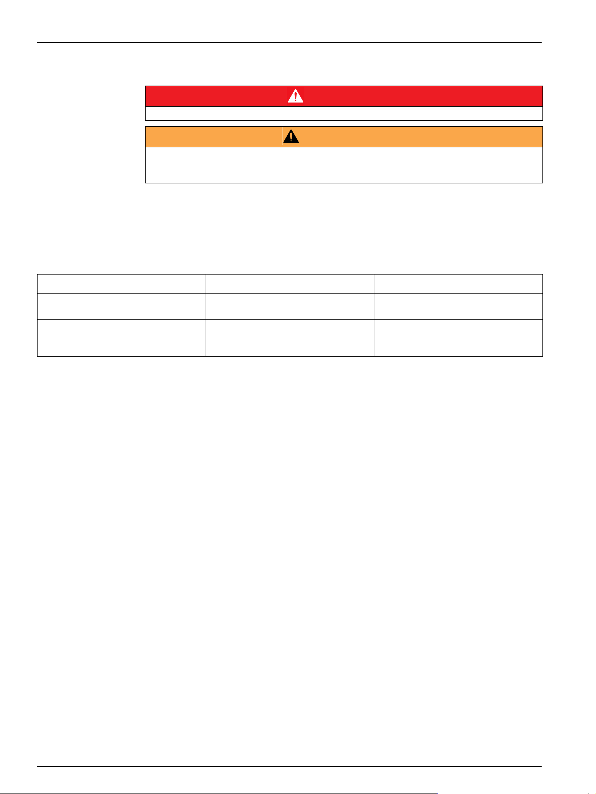
2.4 Product components
Each sensor is supplied with
• a connector cable with safety sleeve,
• a shackle,
• a basic user manual and
Chain mount kit Sensor with or without cleaning unit
Flow cell Sensor without cleaning unit
• a CD.
The sensor is available in a variety of types (refer to section 7.1 on page 27). Refer to
Figure 2 to make sure that all components have been received. If any of these items are
missing or damaged, contact the manufacturer or a sales representative immediately.
8
Page 9
General information
2.4.1 FP 360 sc sensor
Figure 2 FP 360 sc sensor
1 FP 360 sc measurement sensor 5 6 mm fitting for cleaning unit (depending on model)
sic user manual with CD 6 Safety sleeve
2 Ba
3 Me
4 Se
asurement window 7 Connector cable
nsor with cleaning unit (depending on model) 8 Shackle
2.5 Function test
CAUTION
Before power is applied, refer to the controller operation instructions.
After the components are removed from the package, do a function test.
1. Con
2. Ap
nect the connector cable to the sensor (8-pin polarized connector) and an
appropriate sc controller (5-pin polarized connector) (refer to section 3.1 on page 11).
ply power to the sc controller. The display is activated and the sensor goes to
measurement mode.
The sensor ticks quietly and regularly.
9
Page 10

General information
3. Cover the sensor measurement window with a sheet of white paper (do not use
recycled paper).
4. Vary the distance between the measurement window and the paper.
The measurement value on the display will change accordingly.
Note: In air, the measurement value displayed is not exactly zero due to reflections on the window
surface (refer to section 4.5.3 on page 21).
10
Page 11
Section 3Installation
Personal injury hazard. Only qualified personnel should conduct the tasks described in this section
of the manual.
If the sensor is not fully inserted, sun protection is recommended in high ambient temperatures
and intense solar radiation to protect against thermal and UV effects.
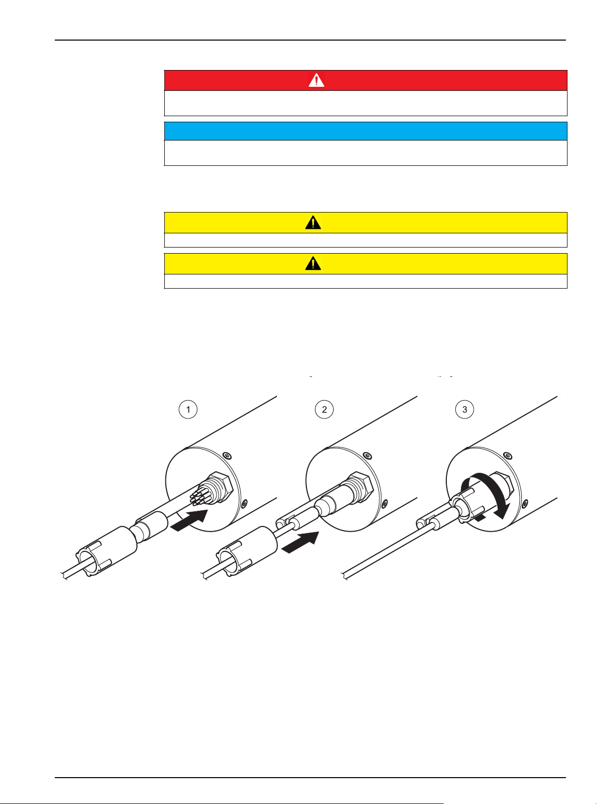
3.1 Connect sensor cable
Always put the cables and hoses in a position that does not bend or cause a trip hazard.
Before power is applied, refer to the controller operation instructions.
1. Connect the polarized socket on the connector cable to the sensor plug (8-pin plug)
(refer to Figure 3 step 1).
DANGER
NOTICE
CAUTION
CAUTION
2. Push the
3. Hand-t
ighten the safety sleeve in position (step 3).
Figure 3 Connect the sensor cable to the sensor
safety sleeve on the plug (step 2).
4. Remo
5. Con
Note: Connector cables are available in various lengths (refer to section 7.2 on page 27). Maximum
overall cable length is 40 m (131,23 ft).
ve the protective cap on the controller socket and keep it to seal the connector
opening in case the sensor must be removed.
nect the sensor to the controller using the keyed quick-connect fitting.
Hand-tighten (refer to Figure 4).
11
Page 12

Installation
6
1 2
5
3
4
Figure 4 Connect the sensor to the controller
Figure 5 Pin configuration
Number Description Standard cable, cable color
1 +12 VDC brown
2 Ground black
3 Data (+) blue
4 Data (–) white
5 Screen Screen (gray)
6 Guide
12
Page 13

3.2 Installation options
The sensor may need to be installed with additional optional accessories depending on
the area of application (refer to section 7.3 on page 27).
Note: Refer to the documentation supplied with the accessories for detailed installation instructions.
3.2.1 Installation with the chain mount kit
The FP 360 sc sensor is installed with the chain mount kit in open channels, shafts and
tanks.
Installation
Figure 6 FP 360 sc measurement sensor with chain mount kit
3.2.2 Installation of chain mount kit for sensors with cleaning unit
3.2.2.1 Install the cleaning unit hose
Note: An air hose is required, to operate the sensor with the optional cleaning unit. An oil-free
compressed air (6 bar) and a solenoid valve or the HOAB compressed air cleaning system is also
required (refer to section
With the HOAB compressed air cleaning system, replace the end of the hose connection
that is connected to the compressed air on the underside of the instrument with the
straight 6 mm fitting (refer to Figure 2 on page 9, item 5) supplied with the probe.
7.3 on page 27).
13
Page 14

Installation
Figure 7 Install the cleaning unit hose
14
Figure 8 FP 360 sc measurement sensor with cleaning unit and chain mount kit
Page 15

3.2.3 Installation with flow cell
The FP 360 sc sensor with flow cell is installed for samples free of solids and particulates
and limited sample flows.
Installation
Figure 9 Installation with flow cell
15
Page 16

Installation
16
Page 17

Section 4 Operation
4.1 User interface and navigation
The sensor can be used with sc controllers from sc100. Refer to the controller
documentation for keypad description and navigation information.
4.2 Sensor setup
When the sensor is connected for the first time, the sensor serial number is displayed as
the name of the sensor. To change the sensor name:
1. Open the MAIN MENU.
2. Select SENSOR SETUP and confirm.
3. Select the corresponding sensor and confirm.
4. Select CONFIGURE and confirm.
5. Select EDIT NAME and confirm.
6. Edit the name and confirm to return to the SENSOR SETUP menu.
Complete sensor configuration in the same manner, with the following menu options
selected:
• SET PARAMETER
• SELECT UNITS
• AVERAGE
• LOG SETUP
• GAIN VALUE
4.3 Sensor data logger
There is a data log and event log available for each sensor.
In the data log, the measurement data are stored at preset intervals; the event log stores
events such as configuration changes, alarm messages and warning messages. Both logs
can be exported to CSV format (refer to the controller manual).
17
Page 18

Operation
4.4 Menu structure
4.4.1 SENSOR STATUS
SELECT SENSOR (if there is more than one sensor)
ERROR LIST Possible error messages: SENSOR ERROR
WARNING LIST
4.4.2 SENSOR SETUP
SELECT SENSOR (if there is more than one sensor)
CALIBRATE
SET OUTMODE Behavior of the outputs during calibration and zero point adjustment
HOLD
ACTIVE
SET TRANSFER
SENSOR MEASURE Current, uncorrected measurement value
CONFIGURE
FACTOR
OFFSET
2 POINT
3 POINT
4 POINT
5 POINT
FACTOR
OFFSET
2 POINT
3 POINT
4 POINT
5 POINT
SET CAL DEFLT Security query, reset to (FACTOR=1, OFFSET=0)
Possible warning messages: TEST/MAINT, BULB CHANGE, LAST CONFIGUR, TARGET
VALUE
Note: Refer to Section 6 on page 25 for a list of all possible error and warning messages
together with a description of all necessary countermeasures to be taken.
FACTOR: 0.1 to 100
OFFSET: –1000 to +1000
Is shown when FACTOR has been selected under CONFIGURE.
Refer to section 4.5 on page 20 for detailed information.
Is shown when OFFSET has been selected under CONFIGURE.
Refer to section 4.5 on page 20 for detailed information.
Is shown when 2 POINT has been selected under CONFIGURE.
Refer to section 4.5 on page 20 for detailed information.
Is shown when 3 POINT has been selected under CONFIGURE.
Refer to section 4.5 on page 20 for detailed information.
Is shown when 4 POINT has been selected under CONFIGURE.
Refer to section 4.5 on page 20 for detailed information.
Is shown when 5 POINT has been selected under CONFIGURE.
Refer to section 4.5 on page 20 for detailed information.
18
Page 19

4.4.2 SENSOR SETUP (Continued)
SELECT SENSOR (if there is more than one sensor)
CONFIGURE
EDIT NAME
SET PARAMETER
SELECT UNITS
AVERAGE
LOG SETUP
GAIN VALUE
SET DEFAULTS
DIAG/TEST
PROBE INFO
SENSOR NAME Device name
EDIT NAME
SERIAL NUMBER Device serial number
RANGE 0 to 500 or 0 to 5000
MODEL NUMBER Item no. Sensor
CODE VERSION Sensor software
COUNTER
OPERATING HOURS Operating hours counter
MAINTENANCE Counter counting down days
BULB CHANGE Counter counting down days
TEST/MAINT
SET OUTMODE Equipment output behavior in the SERVICE menu
HOLD
ACTIVE
SET TRANSFER
SIGNALS
LAMP CURR Flash lamp intensity
DIAG/TEST Zero point and slope check with external standards
REDADING OFFSET
CUBE CAL
Name can include up to 16 characters,
DEFAULT CONFIG: sensor serial number
PAH: Measurement value related to PAH calibration standard
OIL: Measurement value related to oil calibration standard
DEFAULT CONFIG: PAH
ppb, ppm, μg/L, mg/L,
DEFAULT CONFIG: ppb
1 to 300 s,
DEFAULT CONFIG: 3 s
5 s, 30 s, 1 min, 2 min, 3 min, 4 min, 5 min, 6 min, 10 min, 15 min, 30 min,
DEFAULT CONFIG: 10 min
Range 0 to 500 ppb: AUTO, 0.01 to 50, 0.01 to 500,
Range 0 to 5000 ppb: AUTO, 0.01 to 500, 0.01 to 5000
DEFAULT CONFIG: AUTO
Security query,
reset to preset configuration for all menu options listed above.
Password-protected access for the service
Operation
19
Page 20

Operation
4.5 Calibration
4.5.1 Factory calibration
The calibration curve zero point and slope are preset. Retrospective calibration of these
basic settings is generally not required outside of the inspection intervals.
Do regular zero point checks to make sure that impurities or faults are being detected
(refer to section 4.5.3 on page 21).
If the zero signal increases due to the measuring medium components or the installation
conditions, you can compensate for this influence via an offset correction. Carry out a lab
analysis of the sample to do this. If there is no PAH/oil contamination in the measuring
medium, enter the measurement value shown by the device as the offset (refer to section
4.5.4.2 on page 22).
4.5.2 Process calibration/adjustment
The sensor is pre-calibrated with various concentrations of a special calibration standard
in ultra-pure water. These ideal measurement conditions rarely occur in reality. The
measurement values shown are qualitative trend indicators if no adjustment is made to the
on-site measurement conditions.
If you require quantitatively correct measurement values, either a slope adjustment or a
multi-point calibration needs to be carried out. Both of these operations must be carried
out on site using lab analysis data. Basic prerequisites for quantitative measurements are
precise knowledge about the oil type in occurrence and constant measurement conditions,
e.g. in cool water in a heat exchanger. If several oils are present in varying quantities, it is
generally not possible to carry out a quantitative measurement.
If the measurement conditions change, you must check the accuracy of the results again
through lab analyses and make any adjustments where necessary.
The measurement conditions can change in terms of
• Composition of PAH or oil impurities
• Distribution of impurities in water
• Tem p
• Measuring medium composition
• Measurement sensor and measurement window
4.5.2.1 Determination of factors and adjustment of slope
To adjust the slope:
1. At the sensor installation site, draw a lab sample of the measuring medium and
promptly analyze the sample for PAH and oil content.
2. Make a note of the measurement value shown on the controller at the time of the
sample being taken. Make sure the correct unit is shown for the measurement value,
e.g. as ppm oil.
3. Repeat steps 1 and 2 several times.
4. Use the sample value and the value shown on the controller at the time of sampling
to calculate a factor.
20
5. Find an average value from the factors.
Page 21

6. Enter the factor as the slope (refer to section 4.5.4.1 on page 21).
Example for engine oil Example for naphthalene
Lab value: 4.0 ppm oil
Measurement value shown
Calculated factor: 1.67
1
At the time of sampling
1
: 2.4 ppm oil
Lab value: 420 ppb PAH
Measurement value shown1: 120 ppb PAH
Calculated factor: 3.5
It is advisable to adjust the slope if the following conditions apply:
Operation
• If th
• Th
e measuring sample is PAH-/oil free, the measurement value must almost be zero.
e factors calculated from the lab values must enable a sensible average value to be
derived.
If these conditions do not apply, do a multi-point calibration.
Note: If both the zero point and the slope must be changed, use a 2-point calibration (refer to
section 4.5.4.3 on page 22).
4.5.2.2 Multi-point calibration
In the event of a multi-point calibration, enter the lab value as the target value and the
value shown as the actual value. Make sure that all values are entered in the same unit,
e.g. oil in ppm. (refer to section 4.5.4.3 on page 22).
4.5.3 Check the zero point
• Medium: ultra-pure water
• T
arget value: < 1 ppb. Clean the window in the event of deviations.
Use a glass container (not plastic) large enough to enable the measurement to be taken
with an 8 to 10
1000 mL glass beaker). Place a black, non-reflective underlay under the container and
switch off artificial lights during the measurement process.
Note: In air, the measurement value displayed is not exactly zero due to reflections on the window
surface. This is standard sensor behavior and not an indicator of malfunction.
cm distance between the measurement window and the base (e.g. a
Note: Always use
can contain organic compounds.
ultra-pure water. Distilled water and demineralized water are not suitable as these
4.5.4 Adjustment of slope and zero point; multi-point calibration
4.5.4.1 Adjust the slope (FACTOR)
1. Open the MAIN MENU.
2. Select SENSOR SETUP an
3. Sele
4. Select CALIB
5. Select CONFIGURE
6. Sele
7. Enter
8. Go
ct the corresponding sensor and confirm.
RATE and confirm.
and confirm.
ct FACTOR and confirm.
the calculated factor and confirm.
back to the MAIN MENU or the Measurement mode display.
d confirm.
21
Page 22

Operation
4.5.4.2 Adjust the zero point (OFFSET)
1. Open the MAIN MENU.
2. Select SENSOR SETUP and confirm.
3. Select the corresponding sensor and confirm.
4. Select CALIBRATE and confirm.
5. Select CONFIGURE and confirm.
6. Press OFFSET and confirm.
7. Enter the required offset and confirm.
8. Go back to the MAIN MENU or the Measurement mode display.
4.5.4.3 Multi-point calibration (2 to 5-point calibration)
Note: Multi-point calibration means that the pairs must be input in ascending order.
1. Open the MAIN MENU.
2. Select SENSOR SETUP and confirm.
3. Select the corresponding sensor and confirm.
4. Select CALIBRATE and confirm.
5. Select CONFIGURE and confirm.
6. Select the type of calibration, e.g. 2 POINT and confirm.
7. Select 1PAIR and confirm.
8. Edit the TARGET VALUE and confirm.
9. Edit the ACTUAL VALUE and confirm.
10. Repeat the process for 2PAIR and confirm.
11. Go back to the MAIN MENU or the Measurement mode display.
22
Page 23

Section 5 Maintenance
The inside of the sensor is maintenance-free.
The cleanliness of the measurement window in the sensor head has an impact on the
accuracy of measurements. Check the measurement window at regular intervals to make
sure it is clean. The required frequency of these checks is dependent on the measuring
medium. Also do a check in the event of unusually high measurement values and clean
the measurement window if necessary (refer to section 5.3 on page 24).
For sensors with a cleaning unit, adjust the frequency of cleaning to the measurement
conditions. The inspection interval must be shortened to reflect any increase in solid
matter.
Individual components of the suspension device (shackle and chain of the chain mount kit) are
made of stainless steel and may corrode.
5.1 Maintenance schedule
NOTICE
Interval Maintenance task
Visual inspection
System inspection Every 2 years Check plugs and flash bulb.
Calibration check Every 2 years Check calibration
1
When operated according to factory settings and appropriate use
Contact the manufacturer's service department every 2 years to arrange sensor
inspection, testing, calibration and seal replacement. The flash bulb is also replaced every
4 years.
Application-dependent Check for contamination and corrosion.
5.2 Maintenance for the connectors on the sensor
The 8-pin connector on the sensor is designed for constant usage under water. The
connector is lubricated with high-performance grease at the factory and does not require
any additional maintenance from the recommended sensor inspection cycles.
To maintain the performance of the connectors:
• Protect the neoprene components of the connector against high temperatures and
intense solar radiation. If this cannot be avoided, moisten the dried out neoprene
components with clean, clear water. Subsequently, loosen the connector.
• The pins must always be lightly lubricated. Only apply a very thin film of lubricant.
Recommended lubricants are Loctite
The lubricant must not come into contact with the measurement window.
8021 as a spray or Molykote 44 Medium.
1
• Rinse out grains of sand and solid matter from the cable socket.
• To loosen the connector, unscrew the safety sleeve and pull out the plug longitudinally.
• Avoid flexing the plug and pulling on the cable.
• Do not loosen the connector at ambient temperatures below 0 °C. Heat the neoprene
components carefully to temperatures above 0 °C and then loosen the connector.
• Avoid kinks or tight bend in the cables.
23
Page 24

Maintenance
5.3 Cleaning the measurement windows
Cleaning agents can be hazardous to health.
Wear protective equipment and avoid direct contact with cleaning fluids.
Other cleaning agents can damage the material. Damage caused by cleaning carried out
incorrectly is not covered by the warranty.
1. Rinse the sensor with fresh water until all attached solid matter has been removed.
2. Use pure acetone and a soft, clean cloth (e.g. camera lens cleaning paper) to
carefully remove the deposits on the measurement window. Avoid sharp objects on
the measurement window surface.
3. Rinse the residue from the cleaning agent with fresh water.
CAUTION
NOTICE
24
Page 25

Section 6 Troubleshooting
6.1 Error messages
Possible sensor errors displayed by the sc controller.
Displayed errors Definition Resolution
SENSOR ERROR Electronic defect Call manufacturer customer service
6.2 Warnings
Possible sensor warning messages displayed by the sc controller.
Displayed warnings Definition Resolution
DIAG/TEST Counter expired Call manufacturer customer service
BULB CHANGE Counter expired Call manufacturer customer service
LAST CONFIGUR
TAR GET VAL UE
Changed configuration was
not accepted
With multi-point calibration,
values not entered in
ascending order
Send configuration again
Enter calibration values in ascending order
6.3 Replacement parts
Designation Quantity Service life
Flash bulb 1 4 years
O-Rings 4 2 years
25
Page 26

Troubleshooting
26
Page 27

Section 7 Replacement parts and accessories
7.1 Sensor options
Description Cat. no.
Range 0 to 50/500 ppb, stainless steel housing, cable length 10 m without cleaning unit LXV441.99.11101
Range 0 to 50/500 ppb, stainless steel housing, cable length 10 m with cleaning unit and fittings
ot in connection with flow cell)
(n
Range 0 to 50/500 ppb, stainless steel housing, cable length 1.5 m without cleaning unit LXV441.99.11301
Range 0 to 50/500 ppb, titanium housing, cable length 10
Range 0 to 50/500 ppb, titanium housing, cable length 10 m with cleaning unit and fittings (not
in connection with flow cell)
Range 0 to 50/500 ppb, titanium housing, cable length 1.5 m without cleaning unit LXV441.99.12301
Range 0 to 500/5000 ppb, stainless steel housing, cable length 10 m without cleaning unit LXV441.99.21101
Range 0 to 500/5000 ppb, stainless steel housing, cable length 10 m with cleaning unit and
fittings (not in conn
Range 0 to 500/5000 ppb, stainless steel housing, cable length 1.5 m without cleaning unit LXV441.99.21301
Range 0 to 500/5000 ppb, titanium housing, cable length 10 m without cleaning unit
Range 0 to 500/5000 ppb, titanium housing, cable length 10 m with cleaning unit and fittings
(not in connection with flow cell)
Range 0 to 500/5000 ppb, titanium housing, cable length 1.5 m without cleaning unit LXV441.99.22301
ection with flow cell)
m without cleaning unit LXV441.99.12101
LXV441.99.11201
LXV441.99.12201
LXV441.99.21201
LXV441.99.22101
LXV441.99.22201
7.2 Replacement parts
Description Cat. no.
Connector cable 1.5 m LZY623
Connector cable 10 m
Shackle, stainless steel 1.4301 LZY668
Gasket and screw set for flow cell
Fitting set for flow cell LZY626
Pressure ring and angle bracket for flow cell
Chain mount kit instructions DOC273.99.90164
Flow cell instructions DOC273.99.90165
LZY624
LZY625
LZY674
7.3 Accessories
Description Cat. no.
Extension cable (5 m/16.40 ft) LZX848
Extension cable (10 m/32.81 ft)
Extension cable (15 m/49.21 ft) LZX850
Extension cable (20 m/65.62 ft)
Extension cable (30 m/98.43 ft) LZX852
Flow cell on prefabricated wall including gasket set
V4A chain mount kit LZX914.99.11110
HOAB compressed air cleaning system, 230 V
HOAB compressed air cleaning system, 115 V, HACH Lange version 6860003.99.0001
Hose for air and measuring medium 5 m, 6/4 mm external/internal diameter
Hose for air and measuring medium 10 m, 6/4 mm external/internal diameter LZY620
Hose for air and measuring medium 25 m, 6/4 mm external/internal diameter LZY621
LZX849
LZX851
LZY669
6860103.99.0001
LZY619
27
Page 28

Replacement parts and accessories
7.3 Accessories (table continued)
Description Cat. no.
Hose for measuring medium 5 m, 8/6 mm external/internal diameter LZY672
Hose for measuring medium 10 m, 8/6 mm external/internal diameter LZY673
28
Page 29

Section 8 Contact information
HACH Company
World Headquarters
P.O. Box 389
Loveland, Colorado
80539-0389 U.S.A.
Tel (800) 227-HACH
(800) -227-4224
(U.S.A. only)
Fax (970) 669-2932
orders@hach.com
www.hach.com
HACH LANGE GMBH
Willstätterstraße 11
D-40549 Düsseldorf
Tel. +49 (0)2 11 52 88-320
Fax +49 (0)2 11 52 88-210
info@hach-lange.de
www.hach-lange.de
HACH LANGE
Rorschacherstrasse 30 a
CH-9424 Rheineck
Tel. +41 (0)71 886 91 11
Fax +41 (0)71 886 91 66
info@hach-lange.ch
www.hach-lange.ch
Repair Service in the
United States:
HACH Company
Ames Service
100 Dayton Avenue
Ames, Iowa 50010
Tel (800) 227-4224
(U.S.A. only)
Fax (515) 232-3835
HACH LANGE LTD
Pacific Way
Salford
GB-Manchester, M50 1DL
Tel. +44 (0)161 872 14 87
Fax +44 (0)161 848 73 24
info@hach-lange.co.uk
www.hach-lange.co.uk
HACH LANGE FRANCE
S.A.S.
8, mail Barthélémy Thimonnier
Lognes
F-77437 Marne-La-Vallée
cedex 2
Tél. +33 (0)8 20 20 14 14
Fax +33 (0)1 69 67 34 99
info@hach-lange.fr
www.hach-lange.fr
Repair Service in Canada:
Hach Sales & Service
Canada Ltd.
1313 Border Street, Unit 34
Winnipeg, Manitoba
R3H 0X4
Tel (800) 665-7635
(Canada only)
Tel (204) 632-5598
Fax (204) 694-5134
canada@hach.com
HACH LANGE LTD
Unit 1, Chestnut Road
Western Industrial Estate
IRL-Dublin 12
Tel. +353(0)1 46 02 5 22
Fax +353(0)1 4 50 93 37
info@hach-lange.ie
www.hach-lange.ie
HACH LANGE SA
Motstraat 54
B-2800 Mechelen
Tél. +32 (0)15 42 35 00
Fax +32 (0)15 41 61 20
info@hach-lange.be
www.hach-lange.be
Repair Service in
Latin America, the
Caribbean, the Far East,
Indian Subcontinent, Africa,
Europe, or the Middle East:
Hach Company World
Headquarters,
P.O. Box 389
Loveland, Colorado,
80539-0389 U.S.A.
Tel +001 (970) 669-3050
Fax +001 (970) 669-2932
intl@hach.com
HACH LANGE GMBH
Hütteldorferstr. 299/Top 6
A-1140 Wien
Tel. +43 (0)1 9 12 16 92
Fax +43 (0)1 9 12 16 92-99
info@hach-lange.at
www.hach-lange.at
DR. LANGE NEDERLAND
B.V.
Laan van Westroijen 2a
NL-4003 AZ Tiel
Tel. +31(0)344 63 11 30
Fax +31(0)344 63 11 50
info@hach-lange.nl
www.hach-lange.nl
HACH LANGE APS
Åkandevej 21
DK-2700 Brønshøj
Tel. +45 36 77 29 11
Fax +45 36 77 49 11
info@hach-lange.dk
www.hach-lange.dk
HACH LANGE LDA
Av. do Forte nº8
Fracção M
P-2790-072 Carnaxide
Tel. +351 214 253 420
Fax +351 214 253 429
info@hach-lange.pt
www.hach-lange.pt
HACH LANGE KFT.
Vöröskereszt utca. 8-10.
H-1222 Budapest XXII. ker.
Tel. +36 (06)1 225 7783
Fax +36 (06)1 225 7784
info@hach-lange.hu
www.hach-lange.hu
HACH LANGE AB
Vinthundsvägen 159A
SE-128 62 Sköndal
Tel. +46 (0)8 7 98 05 00
Fax +46 (0)8 7 98 05 30
info@hach-lange.se
www.hach-lange.se
HACH LANGE SP.ZO.O.
ul. Opolska 143 a
PL-52-013 Wrocław
Tel. +48 (0)71 342 10-83
Fax +48 (0)71 342 10-79
info@hach-lange.pl
www.hach-lange.pl
HACH LANGE S.R.L.
Str. Căminului nr. 3
Sector 2
RO-021741 Bucureşti
Tel. +40 (0) 21 205 30 03
Fax +40 (0) 21 205 30 17
info@hach-lange.ro
www.hach-lange.ro
HACH LANGE S.R.L.
Via Riccione, 14
I-20156 Milano
Tel. +39 02 39 23 14-1
Fax +39 02 39 23 14-39
info@hach-lange.it
www.hach-lange.it
HACH LANGE S.R.O.
Lešanská 2a/1176
CZ-141 00 Praha 4
Tel. +420 272 12 45 45
Fax +420 272 12 45 46
info@hach-lange.cz
www.hach-lange.cz
HACH LANGE
8, Kr. Sarafov str.
BG-1164 Sofia
Tel. +359 (0)2 963 44 54
Fax +359 (0)2 866 15 26
info@hach-lange.bg
www.hach-lange.bg
HACH LANGE S.L.U.
Edif. Arteaga Centrum
C/Larrauri, 1C- 2ª Pl.
E-48160 Derio/Vizcaya
Tel. +34 94 657 33 88
Fax +34 94 657 33 97
info@hach-lange.es
www.hach-lange.es
HACH LANGE S.R.O.
Roľnícka 21
SK-831 07 Bratislava –
Vaj nory
Tel. +421 (0)2 4820 9091
Fax +421 (0)2 4820 9093
info@hach-lange.sk
www.hach-lange.sk
HACH LANGE SU
ANALİZ SİSTEMLERİ
LTD. ŞTİ.
Hilal Mah. 75. Sokak
Arman Plaza No: 9/A
TR-06550 Çankaya/ANKARA
Tel. +90 (0)312 440 98 98
Fax +90 (0)312 442 11 01
bilgi@hach-lange.com.tr
www.hach-lange.com.tr
29
Page 30

Contact information
HACH LANGE D.O.O.
Fajfarjeva 15
SI-1230 Domžale
Tel. +386 (0)59 051 000
Fax +386 (0)59 051 010
info@hach-lange.si
www.hach-lange.si
HACH LANGE MAROC
SARLAU
Villa 14 – Rue 2 Casa
Plaisance
Quartier Racine Extension
MA-Casablanca 20000
Tél. +212 (0)522 97 95 75
Fax +212 (0)522 36 89 34
info-maroc@hach-lange.com
www.hach-lange.ma
ΗΑCH LANGE E.Π.Ε.
Αυλίδος 27
GR-115 27 Αθήνα
Τηλ . +30 210 7777038
Fax +30 210 7777976
info@hach-lange.gr
www.hach-lange.gr
HACH LANGE E.P.E.
27, Avlidos str
GR-115 27 Athens
Tel. +30 210 7777038
Fax +30 210 7777976
info@hach-lange.gr
www.hach-lange.gr
HACH LANGE D.O.O.
Ivana Severa bb
42 000 Varaždin
Tel. +385 (0) 42 305 086
Fax +385 (0) 42 305 087
info@hach-lange.hr
www.hach-lange.hr
30
Page 31

Section 9 Warranty and Liability
The manufacturer warrants that the product supplied is free of material and manufacturing
defects and undertakes the obligation to repair or replace any defective parts at zero cost.
The warranty runs for 24 months. If a maintenance contract is taken out within 6 months of
purchase, the warranty period is extended to 60 months.
With the exclusion of the further claims, the supplier is liable for defects including the lack
of assured properties as follows: all those parts that, within the warranty period calculated
from the day of the transfer of risk, can be demonstrated to have become unusable or that
can only be used with significant limitations due to a situation present prior to the transfer
of risk, in particular due to incorrect design, poor materials or inadequate finish will be
improved or replaced, at the supplier's discretion. The identification of such defects must
be reported to the supplier in writing without delay, but no later than 7 days after the
identification of the fault. If the customer fails to notify the supplier, the product is
considered approved despite the defect. Further liability for any direct or indirect damages
is not accepted.
If instrument-specific maintenance and servicing work defined by the supplier is to be
performed within the warranty period by the customer (maintenance) or by the supplier
(servicing) and these requirements are not met, claims for damages due to the failure to
comply with the requirements are rendered void.
Any further claims, in particular claims for consequential damages cannot be made.
Consumables and damage caused by improper handling, poor installation or incorrect use
are excluded from this clause.
The process instruments of the manufacturer are of proven reliability in many applications
and are therefore often used in automatic control loops to provide the most economical
possible operation of the related process.
To avoid or limit consequential damage, it is therefore recommended to design the control
loop such that a malfunction in an instrument results in an automatic change over to the
backup control system. This establishes the most secure operating condition for the
environment and for the process.
31
Page 32

Warranty and Liability
32
Page 33

Appendix A Modbus register
Table 1 Sensor Modbus registers
Register# Data type Length R/W Description
40001 Unsigned integer 1 R Reserved
40002 Float 2 R Measurement value as PAH, unit PPB
40004 Float 2 R Measurement value as PAH, unit PPM
40006 Float 2 R Measurement value as OIL, unit PPB
40008 Float 2 R Measurement value as OIL, unit PPM
40016 String 6 R Serial number
40022 String 8 R/W Name of location
40030 Unsigned integer 1 R/W Choose the parameter, 47=PAH, 48=OIL
40031 Unsigned integer 1 R/W
40040 Float 2 R/W Offset for calibration
40042 Float 2 R/W Factor for calibration
40050 Unsigned integer 1 R/W Logging interval from 5 sec to 1800 sec
40051 Unsigned integer 1 R/W Measuring interval from 1 sec to 300 sec
40052 Unsigned integer 1 R/W
40055 Unsigned integer 1 R/W Set output mode for calibration
40056 Unsigned integer 1 R/W Set output mode for service
40057 Float 2 R Version of application file
40059 Float 2 R The entry is for the application file
40061 Float 2 R Version of the probe
40063 Unsigned integer 1 R The entry is for the device driver file
40064 Unsigned integer 1 R The entry is for the device driver file
40065 Unsigned integer 1 R The entry is for the device driver file
40066 Integer 1
40067 Integer 1 R
40068 Unsigned integer 2 R Operating hours of analyzer
R
Measurement units
38=ppb, 39= g/L, 2=ppm, 0=mg/L
Amplification for the low/high range probe,
AUTO,
0=
1= 0.01 to 50/500 PPB,
2= 0.01 to 500/5000 PPB
Days left until exchanging lamp,
negative values show that exchange is overdue
Days left until maintenance,
negative values show that service is overdue
33
Page 34

Modbus register
34
Page 35

Index
A
Areas of application ................................................... 8
C
Calibration .................................................................. 5
Chain mount kit ........................................................ 13
D
Data logger .............................................................. 17
Dimensions ................................................................ 6
E
Error messages ........................................................ 25
F
Flow cell ................................................................... 15
Function test .............................................................. 9
I
Inspection interval ...................................................... 6
Measurement accuracy .............................................. 5
Measuring method ..................................................... 5
Measuring principle .................................................... 8
Measuring range ........................................................ 5
Modbus register ....................................................... 33
P
Precautionary labels ................................................... 7
Pressure range ........................................................... 5
Product contents ........................................................ 8
R
Reproducibility ............................................................ 5
Response time ........................................................... 5
S
Safety information ...................................................... 7
Safety sleeve ............................................................ 11
Specifications ............................................................. 5
System configuration ................................................ 17
M
Maintenance schedule ............................................. 23
W
Warnings .................................................................. 25
Wearing parts ........................................................... 25
35
Page 36

Index
36
 Loading...