

Page 1
DOC023.52.90173
FILTRAX eco
User Manual
08/2012, Edition 3A
© HACH-LANGE GmbH, 2009, 2012. All rights reserved. Printed in Germany
Page 2

Page 3

Table of Contents
Section 1 Specifications ........................................................................................................................ 5
1.1 Dimensions ....................................................................................................................................... 6
Section 2 General Information............................................................................................................... 7
2.1 Safety information............................................................................................................................... 7
2.1.1 Danger notes in this manual ...................................................................................................... 7
2.1.2 PWarning labels......................................................................................................................... 7
2.2 General Information ............................................................................................................................ 8
2.2.1 Areas of application ................................................................................................................... 8
2.2.2 Functional description................................................................................................................ 8
2.3 Product contents............................................................................................................................... 10
2.4 Instrument design ............................................................................................................................. 11
2.4.1 Control unit............................................................................................................................... 11
2.4.2 Module carrier.......................................................................................................................... 12
2.4.3 Sample tubes........................................................................................................................... 12
2.4.4 Filter module ............................................................................................................................ 13
Section 3 Installation............................................................................................................................ 15
3.1 Unpacking......................................................................................................................................... 16
3.2 Installation......................................................................................................................................... 16
3.3 Mechanical installation...................................................................................................................... 17
3.3.1 Attach the control unit to a wall................................................................................................ 17
3.3.2 Install pump cassette ............................................................................................................... 19
3.3.3 Install suction tube .................................................................................................................. 20
3.3.4 Install sample tube................................................................................................................... 22
3.4 Electrical Connections ...................................................................................................................... 24
3.5 Connection to process measuring instruments................................................................................. 26
3.6 Attach filter module to the module carrier......................................................................................... 28
3.7 Commission the instrument .............................................................................................................. 29
3.7.1 Filter module ............................................................................................................................ 29
Section 4 Operation..............................................................................................................................31
4.1 Control unit operation ....................................................................................................................... 31
4.2 Overview of control unit menu .......................................................................................................... 31
4.3 [+DEVICEDATA] menu..................................................................................................................... 32
4.3.1 Overview of +DEVICEDATA menu.......................................................................................... 32
4.4 [+SIGNALS] menu ............................................................................................................................ 33
4.4.1 Overview of +SIGNALS menu ................................................................................................. 33
4.5 [+OP.COUNTERS] menu ................................................................................................................. 33
4.5.1 Overview of +OP.COUNTERS menu ...................................................................................... 33
4.6 [+SERVICE] menu............................................................................................................................ 33
4.6.1 Overview of +SERVICE menu ................................................................................................. 34
3
Page 4

Section 5 Maintenance..........................................................................................................................35
5.1 Maintenance tasks ............................................................................................................................35
5.1.1 Weekly......................................................................................................................................36
5.1.2 Every 3 months ........................................................................................................................37
5.1.3 Every 6 months ........................................................................................................................38
5.1.4 Every 12 months ......................................................................................................................38
5.2 Cleaning ............................................................................................................................................39
5.2.1 Menu-controlled cleaning tasks................................................................................................39
5.2.2 Cleaning tasks with optional cleaning container LZX216.........................................................40
5.2.3 Cleaning tasks with optional cleaning set LZX217...................................................................42
5.3 Instrument decommissioning and storage.........................................................................................43
5.3.1 Filter module.............................................................................................................................43
5.3.2 Control unit...............................................................................................................................43
Section 6 Troubleshooting ...................................................................................................................45
6.1 Messages..........................................................................................................................................45
6.2 Warnings ...........................................................................................................................................45
6.3 Malfunctions ......................................................................................................................................46
6.4 Voltage drop (power failure)..............................................................................................................46
Section 7 Spare Parts and Accessories ............................................................................................47
7.1 Replacement parts ............................................................................................................................47
7.2 Accessories.......................................................................................................................................47
Section 8 Contact..................................................................................................................................49
Section 9 Warranty and Liability..........................................................................................................51
Index.......................................................................................................................................................53
4
Page 5
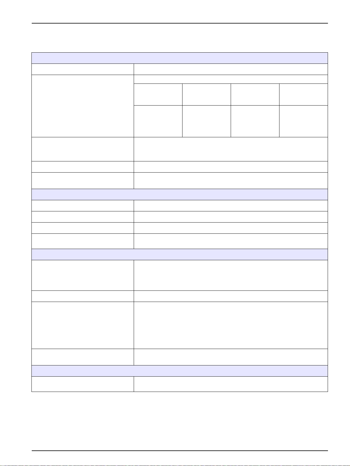
Section 1 Specifications
Subject to change without notice
Electrics
Power supply 230 V (Option: 115 V) ±10 % AC voltage, 50/60 Hz
Device with system components: 1500 VA
Power consumption
Outputs
(Use screened cables!)
Protection type (control unit) IP55
Fuses
Environment
Fault contact: potential-free contact (230 V, max. 3 A)
Alarm contact: potential-free contact (230 V, max. 3 A)
Service interface: RS 232
T 4A E; 250V (2 x)
T 7A E; 250V (2 x)
Line Heater off
2 m [6.56 ft]
10 m [32.8 ft]
20 m [65.6 ft]
30 m [98.4 ft]
150 VA
150 VA
150 VA
150 VA
(–20 °C [–4 °F])
1500 VA
2100 VA
Max.
start-up
450 VA
950 VA
Cont.
(–20 °C [–4 °F])
< 200 VA
< 300 VA
< 400 VA
< 500 VA
Medium temperature +5 °C to +40 °C [41 °F to 104 °F]
Ambient temperature –20 °C to +40 °C [–4 °F to 104 °F]
Sample quantity Approx. 600 mL/h for up to 2 process photometers
Delivery height
General specifications
Line length
Maintenance requirements Approx. 1 hour/month
Weight
Dimensions (W × H × D)
Certification
Module carrier — control unit: 3 m [9.84 ft]
Control unit — process measuring instrument: 7 m [22.97 ft]
Suction tube (heated): 5 m [16.4 ft]
Sample tube (unheated): 2 m [6.56 ft]
Sample tube (heated): 2 m [6.56 ft], 10 m [32.8 ft], 20 m [65.6 ft],
30 m [98.4 ft]
Control unit: approx. 20 kg [44 lb]
Module carrier with 5 m [16.4 ft] suction tube: approx. 3.5 kg [77 lb]
2 m [6.56 ft] sample tube: approx. 1 kg [2.2 lb]
10 m [32.8 ft] sample tube: approx. 5 kg [11 lb]
20 m [65.6 ft] sample tube: approx. 10 kg [22 lb]
30 m [98.4 ft] sample tube: approx. 15 kg [33 lb]
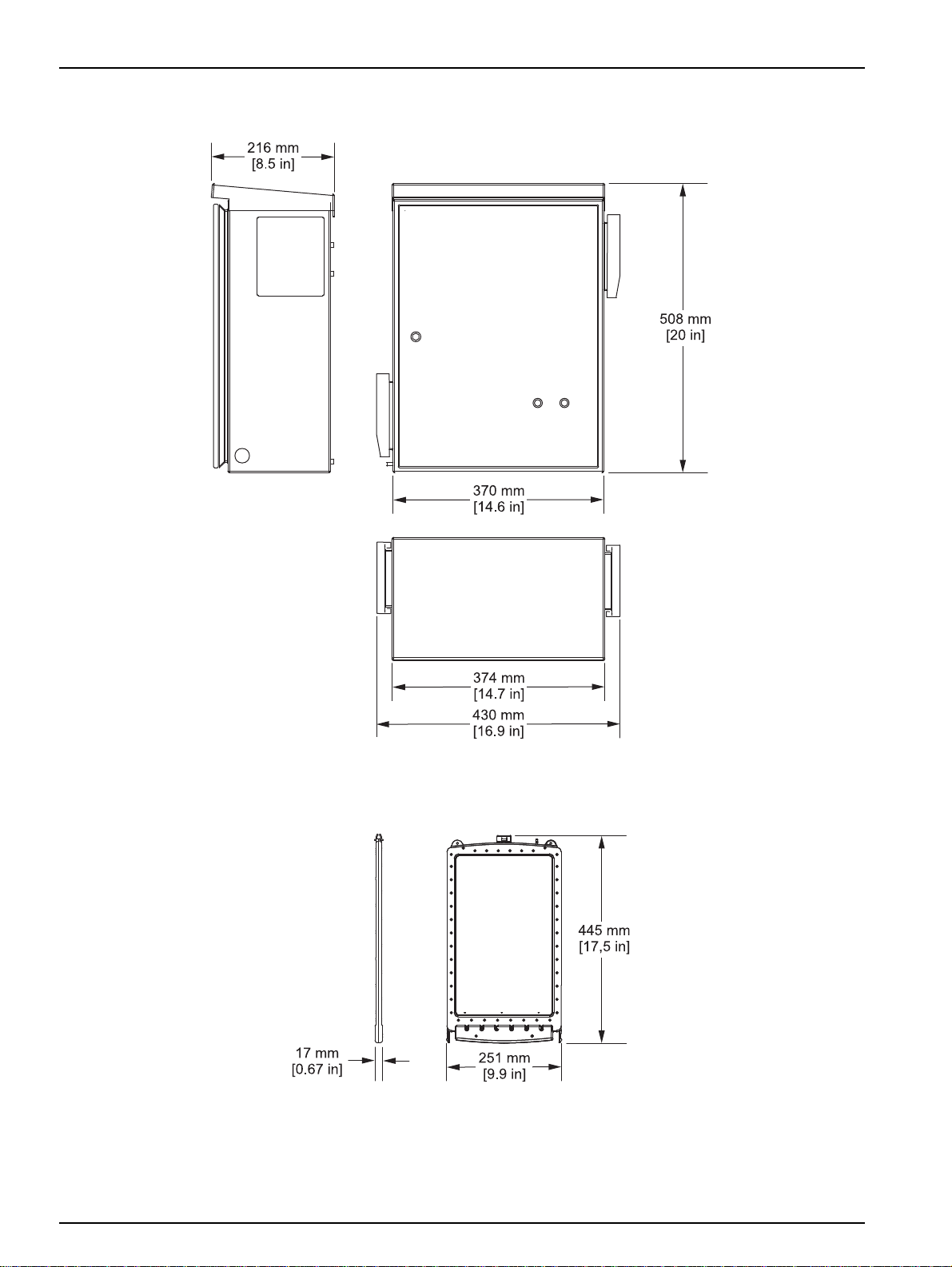
Control unit: 430 × 530 × 220 mm [16.9 × 20.86 × 8.66 in.]
Filter module: 251 × 445 × 17 mm [9.9 × 17.5 × 0.67 in.]
Certification
CE. The manufacturer clarifies conformity with the applicable EU safety
guidelines and EMC guidelines.
5
Page 6
Specifications
1.1 Dimensions
Figure 1 Control unit dimensions
Figure 2 Filter module dimensions
6
Page 7
Section 2 General Information
2.1 Safety information
Please read this entire manual before unpacking, setting up, or
operating this equipment. Pay attention to all danger and caution
statements. Failure to do so could result in serious injury to the
operator or damage to the equipment.
To ensure that the protection provided by this equipment is not
impaired, do not use or install this equipment in any manner other
than that specified in this manual.
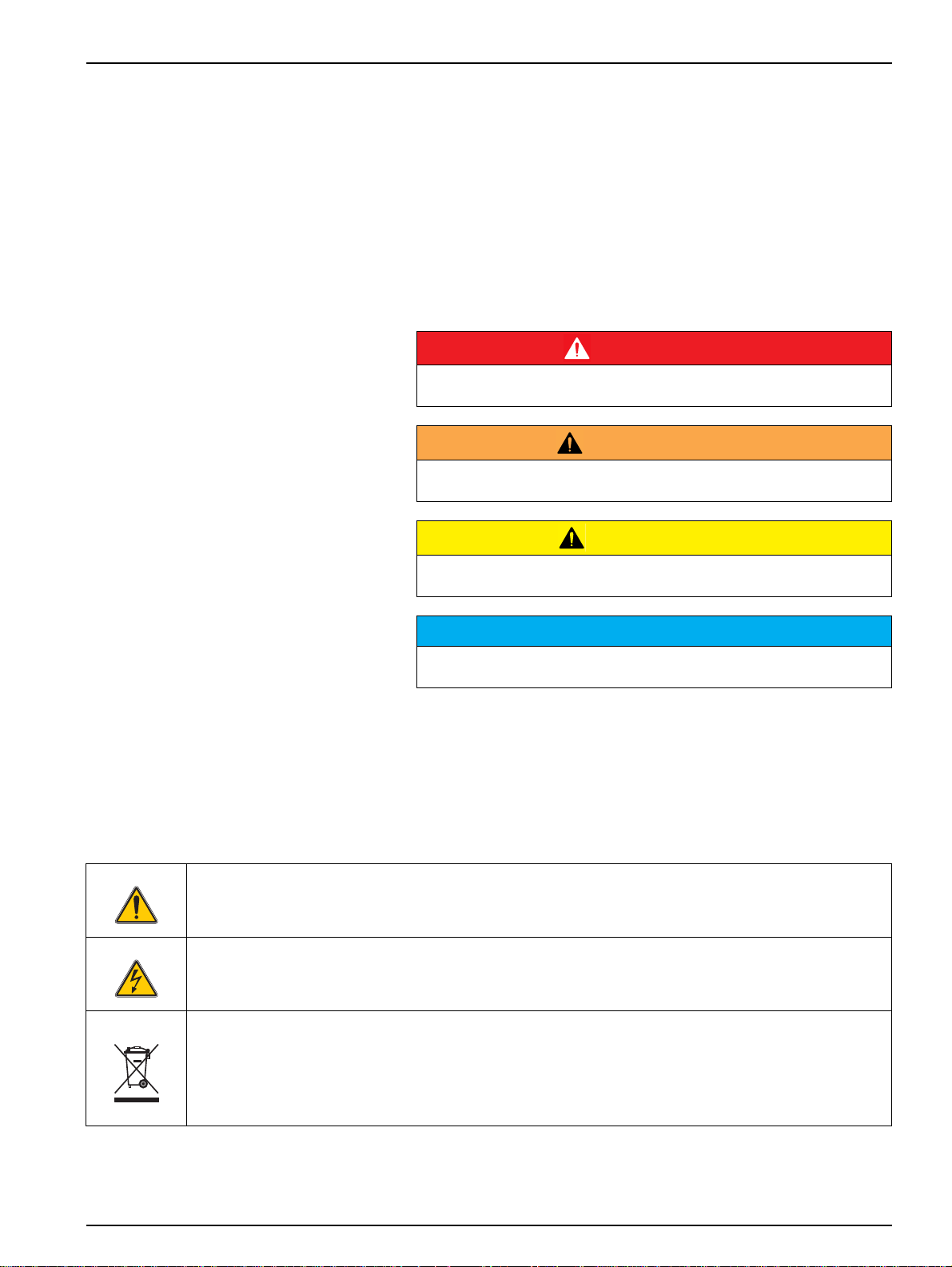
2.1.1 Danger notes in this manual
Indicates a potentially or imminently hazardous situation that, if not
avoided, results in death or serious injury.
Indicates a potentially or imminently hazardous situation that, if not
avoided, could result in death or serious injury.
DANGER
WARNING
2.1.2 PWarning labels
This symbol is a warning triangle. Follow all safety notes that follow this symbol to avoid potential injuries. If
this symbol is located on the instrument, it refers to information in the operating and/or safety instructions of
this manual.
This symbol may be found on an enclosure or barrier within the product and indicates a risk of electrical
shock and/or death by electrocution.
CAUTION
Indicates a potentially hazardous situation that may result in minor or
moderate injury.
NOTICE
Indicates a situation that, if not avoided, could result in damage to the
instrument. Information that particularly should be emphasized.
Note: Information that supplements aspects from the main text.
Observe all marks and labels that are attached to the device.
Nonobservance can result in personal injury or damage to the
device.
Electrical equipment marked with this symbol may as of August 12, 2005 Europe-wide no longer be disposed
of in unsorted house or industrial waste. According to valid provisions (EU Directive 2002/96/ EC), from this
point consumers in the EU must return old electrical devices to the manufacturer for disposal. This is free for
the consumer.
Note: Instructions on the correct disposal of all (marked and unmarked) electrical products supplied or
manufactured by Hach Lange can be obtained from your local Hach Lange sales office.
7
Page 8

General Information
2.2 General Information
2.2.1 Areas of application
2.2.2 Functional description
The FILTRAX eco sampling system is used to filter and deliver
waste water samples from the activation basin in order to supply
downstream process measuring instruments with a sample free
from solid matter.
NOTICE
Any use other than that defined in the operating instructions as correct
use will result in the loss of any rights to make claims under the warranty
and may result in injury or damage for which the manufacturer accepts
no liability.
The FILTAX eco sampling and preparation system comprises three
components: a control unit, a module carrier and a filter module.
The filter module (refer to Figure 3, item 4) is immersed with a
module carrier (refer to Figure 3, item 1) at the sample location
with an optional basin edge attachment. The filter module has a
filter membrane covering both sides. This membrane is used to
suck in and filter the waste water sample, and then feed it to the
control unit.
A pump within the control unit sucks the sample from the filter
module through a 5 m [16.4 ft] long heated suction tube to the
control unit, which is installed right next to the sampling location.
The sample is then pumped over 2, 10, 20 or 30 m [6.56, 32.8, 65.6
or 98.4 ft]—depending on the sample tube connected—to the
process measuring instruments.
The sample delivery is interrupted once a minute for 10 seconds in
order to minimize the amount of solid matter adhesion on the filter
membranes.
8
Page 9
General Information
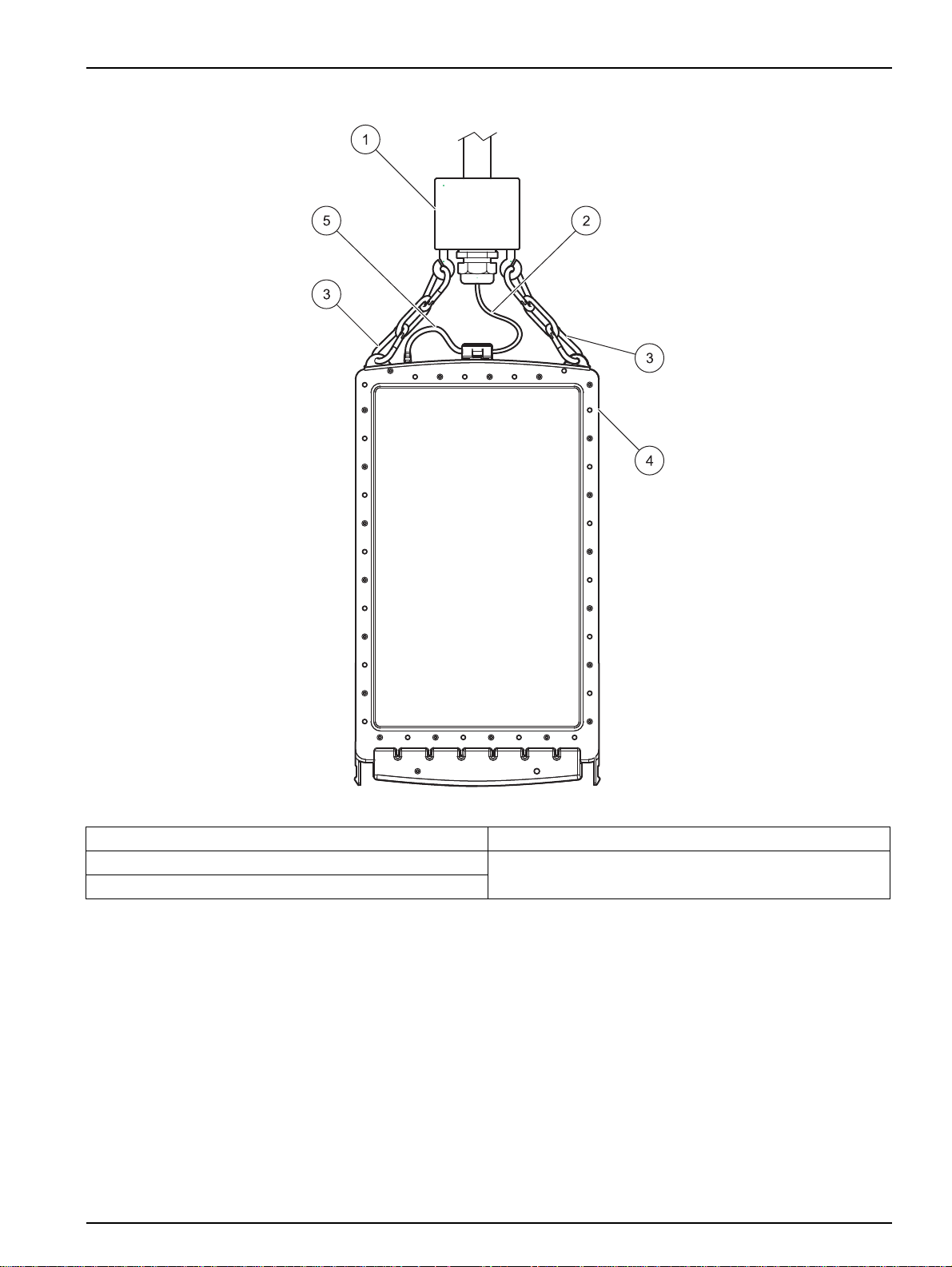
Figure 3 Filter module design
1 Module carrier 4 Filter module
2 Sample suction tube 5 Suction tube, module side
3 Karabiner
9
Page 10
General Information
2.3 Product contents
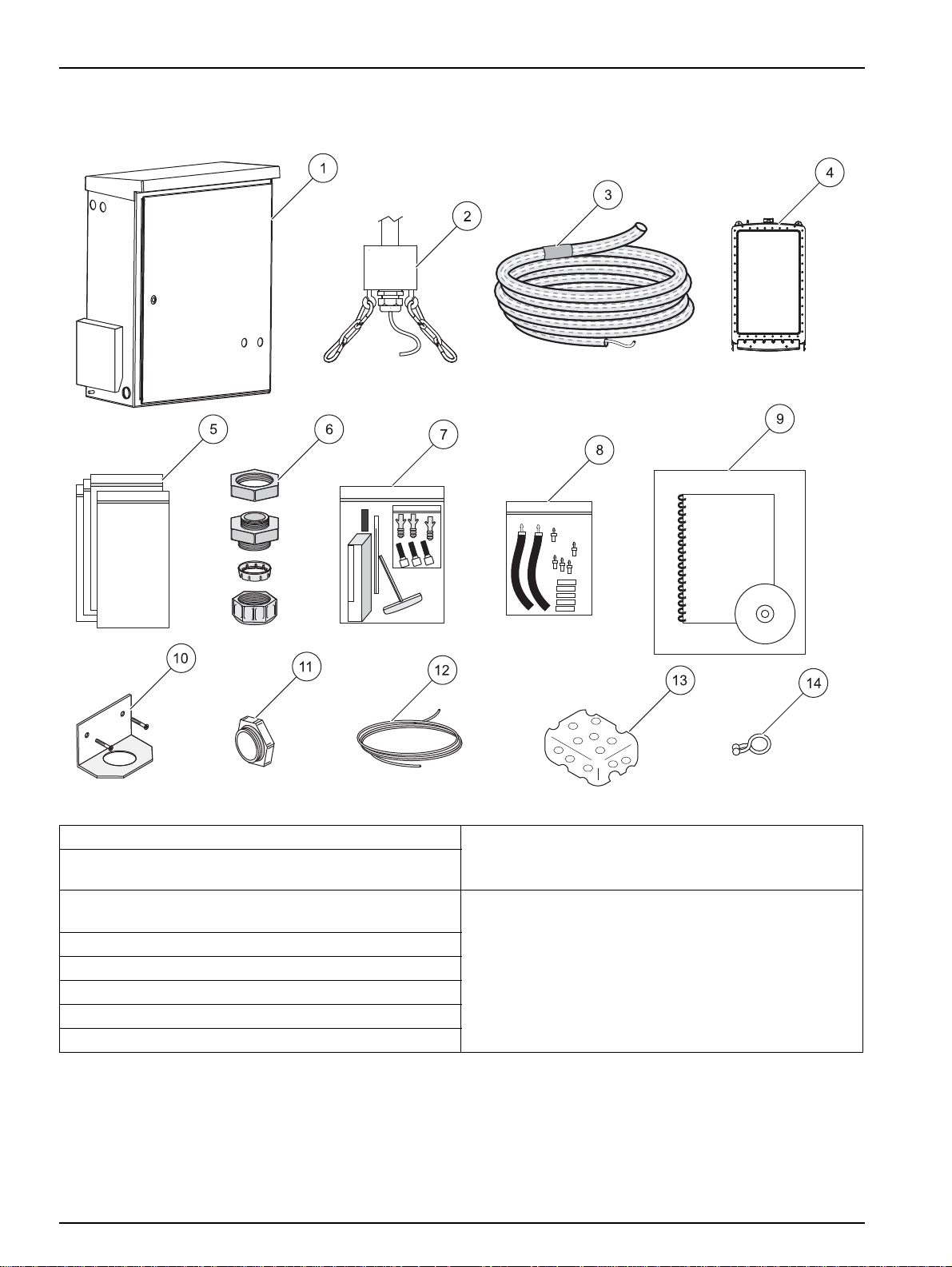
Figure 4 Product contents
1 Control unit 9 Documentation (operating instructions, certificate of
2 Module carrier (LZY678, 230 V) (LZY677, 115 V)
with 5 m [16.4 ft] heated suction tube
3 Sample tube
2, 10, 20 or 30 m [6.56, 32.8, 65.6 or 98.4 ft]
4 LZX677 filter module
5 EYV017 plastic bag for filter module storage (4×)
6 Cable gland M20 × 1.5 (2×)
7 LZX702 accessory set
8 LZX701 tube adapter set
compliance, DOC273.xx.90174 maintenance schedule
(xx = language code)
Included in accessory set LZX702
10 Installation bracket for sample tube
11 Dummy plugs (2×) + seals (2×)
12 HLS191 size 2/4 tube, 6 m [19.7 ft]
13 Cleaning sponge
14 Bundle clip
10
Page 11
2.4 Instrument design
2.4.1 Control unit
General Information
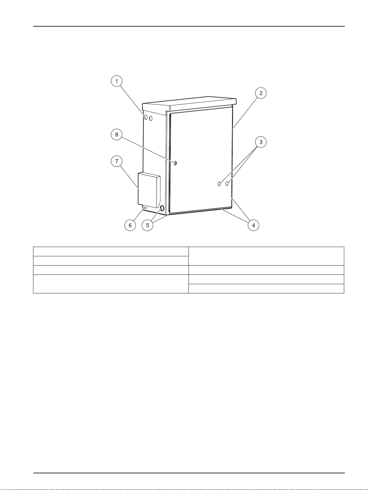
Figure 5 Control unit
1 PG fitting for electrical connection cable (2x) 5 Suction tube connection (left or left underside) (dummy
2 Air filter cover (air outlet)
3 Red and green indicator lights 6 Connection for equipotential bonding
4 Sample tube connection (right or right underside)
(dummy plug and seal for unused opening)
plug and seal for unused opening)
7 Air filter cover (air inlet)
8 Lock
11
Page 12
General Information
1
2
3
2
4
2.4.2 Module carrier
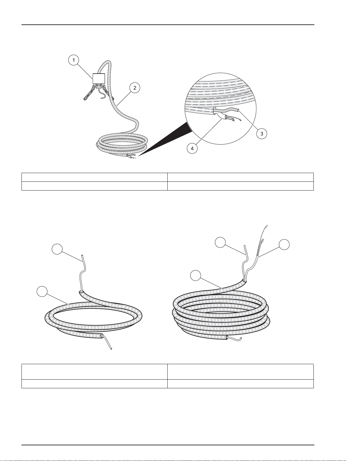
Figure 6 Module carrier
1 Module carrier 3 Sample suction tube, 3.2 mm [0.1 in.] external Ø
2 5 m [16.4 ft] suction tube 4 Heat tracing connection line
2.4.3 Sample tubes
1 Sample tube, 23 mm [0.91 in.], unheated,
2 m [6.56 ft]
2 Sample pressure tube 3.2 mm [0.1 in.] external Ø 4 Heat tracing connection line
Figure 7 Sample tubes
3 Sample tube, 23 mm [0.91 in.], heated,
2, 10, 20 or 30 m [6.56, 32.8, 65.6 or 98.4 ft]
12
Page 13
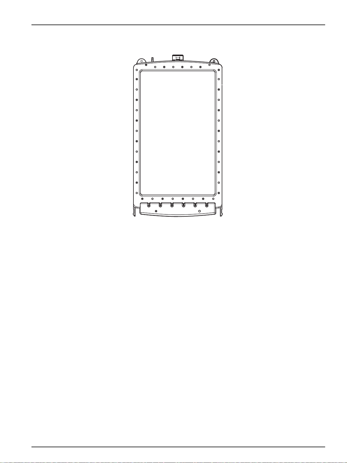
2.4.4 Filter module
General Information
Figure 8 Filter module
13
Page 14

General Information
14
Page 15
Section 3 Installation
DANGER
Only qualified experts should conduct the tasks described in this section.
DANGER
Select an appropriate installation location for the instrument.
Plan out the mechanical mount before positioning poles or drilling holes.
Make sure the mount has a sufficient bearing capacity. The dowels must
be selected and authorized according to the condition of the wall.
The manufacturer shall accept no liability if the instrument is installed
incorrectly.
Plan how to lay cables and tubes and their path in advance. Lay the
tubes, data cables and power cables without any bends and so they do
not pose a tripping risk.
Do not connect the electrical supply to the mains until the instrument is
completely wired and protected against short circuits.
Sufficiently protect the electrical power supply against short circuits.
For the external power supply, always connect a residual-current circuit
breaker (trip current max.: 30 mA) between the mains and the system.
If the instrument is to be installed outdoors, connect a surge arrester
between the mains and the system.
Products intended by the manufacturer for outdoor use offer a higher
level of protection against the penetration of liquids and dust. If these
products are connected to a mains outlet with a cable and plug rather
than a permanently connected cable, the plug and outlet are much more
susceptible to liquid and dust penetration. The operator must sufficiently
protect the plug and outlet against liquid and dust penetration in
accordance with local safety regulations. If the instrument is to be used
outdoors, it must be connected to a suitable outlet with a protection type
of at least IP44 (splash protection).
WARNING
Electrical dangers and fire hazard. Use only the supplied power cable.
Only qualified experts may perform the tasks described in this section of
the manual, in compliance with all locally applicable safety regulations.
NOTICE
Protect the device against extreme temperatures from heaters, direct
sunlight and other heat sources.
CAUTION
Note the weight (control unit approx. 20 kg, module carrier with 5 m
suction tube approx. 3,5 kg) of the instrument. Do not try to carry the
instrument without help. Use only suitable lifting devices for the
transport.
15
Page 16

Installation
3.1 Unpacking
3.2 Installation
NOTICE
The filter module should only be unpacked directly before
commissioning and quickly attached to the module carrier. The filter
membranes are packed in protective plastic; once they have been
moistened they must not be allowed to dry out.
Figure 9 Example of installation
with optional control unit bracket LZX676 and optional basin edge attachment LZX414.00.XXXXX
1 Control unit 5 Module carrier with filter module
2 Process instrument 6 Bracket for FILTRAX eco module carrier (optional)
3 Sample tube 7 5 m [16.4 ft] suction tube
4 Bracket for FILTRAX eco control unit (optional)
16
Page 17
3.3 Mechanical installation
Installation
DANGER
Select an appropriate installation location for the instrument.
Plan out the mechanical mount before positioning poles or drilling holes.
Make sure the mount has a sufficient bearing capacity. The dowels must
be selected and authorized according to the condition of the wall.
The manufacturer shall accept no liability if the instrument is installed
incorrectly.
Plan how to lay cables and tubes and their path in advance.
Lay the tubes, data cables and power cables without any bends and so
they do not pose a tripping risk.
NOTICE
For information on installation with optional accessories, refer to the
relevant installation instructions.
NOTICE
The filter module should only be unpacked directly before
commissioning and quickly attached to the module carrier.
The filter membranes are shrink-wrapped in protective plastic; once they
have been moistened they must not be allowed to dry out.
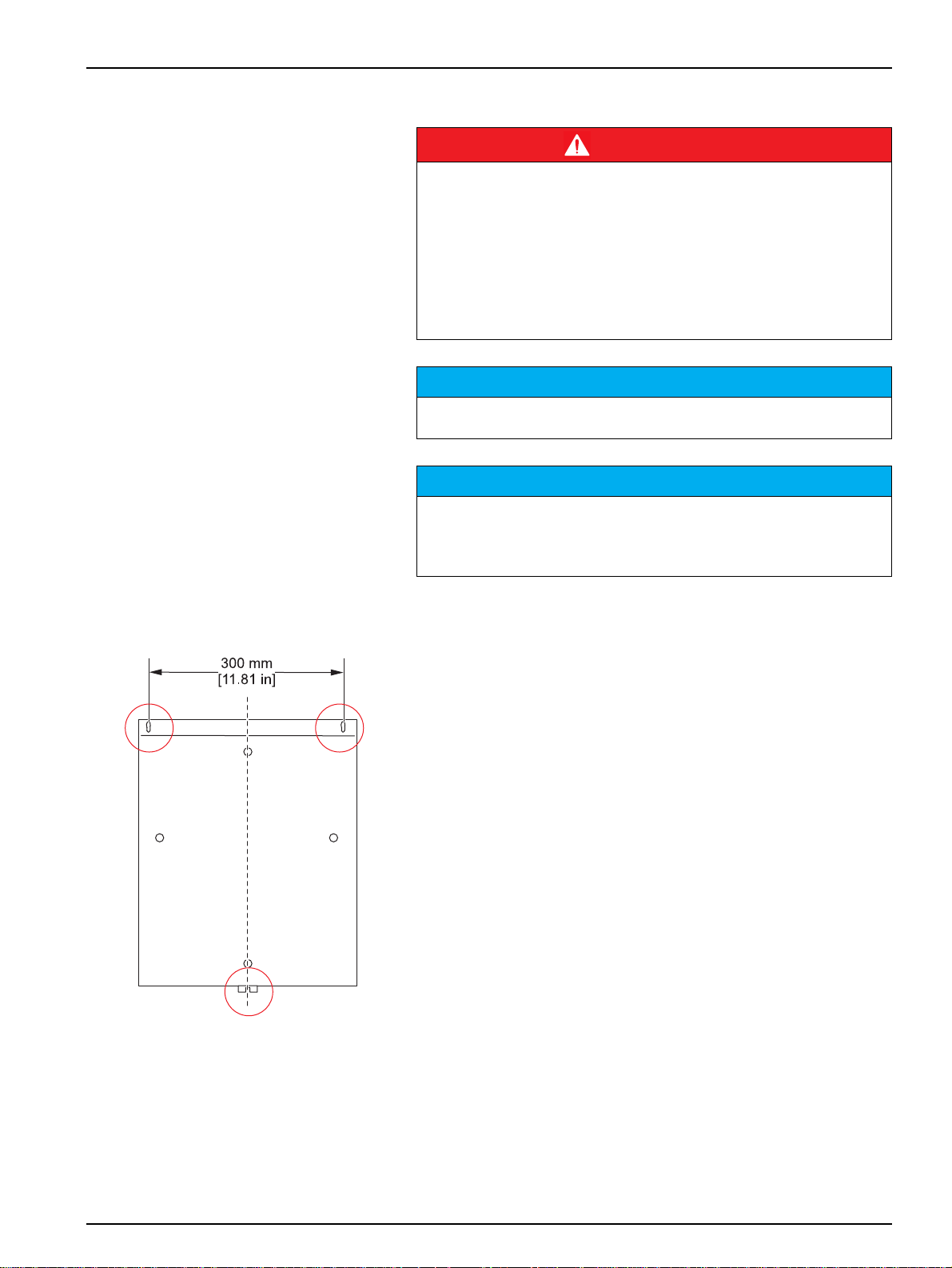
3.3.1 Attach the control unit to a wall
1. Select a suitable attachment point for the instrument.
2. Drill the top two holes in accordance with the adjacent diagram.
3. Attach the instrument at the top two mounts and mark the lower
4. Drill the bottom hole and finish attaching the instrument.
Make sure that there is sufficient space for tubes, cabling and
maintenance operations.
mount.
17
Page 18

Installation
Figure 10 Attachment example, wall mount
18
Page 19

3.3.2 Install pump cassette
Installation
Figure 11 Click pump cassette into place
19
Page 20

Installation
3.3.3 Install suction tube
Figure 12 Suction tube connection preparation
1 Protective tube (transportation safety device) 4 Cable gland M20 × 1.5
2 Heat-shrink tube 5 Suction tube
3 Metal connection 6 Dummy plug
NOTICE
Make sure the tubes are connected correctly. The filter module may be
damaged if the sample is sucked back via the sample suction tube.
20
Page 21

Installation
1
2
3
4
Figure 13 Suction tube connection
1 Suction tube 3 Pump cassette
2 Heat tracing connection cable 4 Sample suction tube
21
Page 22

Installation
3.3.4 Install sample tube
Figure 14 Sample tube connection preparation
1 Protective tube (transportation safety device) 4 Cable gland M20 × 1.5
2 Heat-shrink tube 5 Suction tube
3 Metal connection 6 Dummy plug
22
Page 23

Installation
Figure 15 Sample tube connection
1 Pump cassette 3 Sample tube
2 Sample pressure tube 4 Heat tracing connection cable
23
Page 24

Installation
3.4 Electrical Connections
DANGER
Do not connect the electrical supply to the mains until the instrument is
completely wired and protected against short circuits.
Sufficiently protect the electrical power supply against short circuits.
For the external power supply, always connect a residual-current circuit
breaker (trip current max.: 30 mA) between the mains and the system.
If the instrument is to be installed outdoors, connect a surge arrester
between the mains and the system.
If the mains plug of the power supply cable is removed, a suitable
double-pole one-way switch must be installed immediately next to the
display unit with clear labeling for the power supply.
Products intended by the manufacturer for outdoor use offer a higher
level of protection against the penetration of liquids and dust. If these
products are connected to a mains outlet with a cable and plug rather
than a permanently connected cable, the plug and outlet are much more
susceptible to liquid and dust penetration. The operator must sufficiently
protect the plug and outlet against liquid and dust penetration in
accordance with local safety regulations. If the instrument is to be used
outdoors, it must be connected to a suitable outlet with a protection type
of at least IP44 (splash protection).
WARNING
Only qualified experts may perform the tasks described in this section of
the manual, in compliance with all locally applicable safety regulations.
NOTICE
Use only earthed sockets for the connection of this device to the power
supply.
If it is not clear whether the sockets are earthed, have this checked by a
qualified electrician.
In addition to supplying power, the power plug also serves to isolate the
device quickly from the mains where necessary.
The entire measurement system has two power plugs (measurement
device and control unit). During the disconnection from the mains, it
must be made sure that the correct power plug is pulled (e.g. labeling of
the sockets).
This is recommended for long-term disuse and can prevent potential
dangers in the event of a fault.
Therefore make sure that the sockets to which the device is connected
are easy to reach by each user at all times.
NOTICE
On removal of the power plug (fixed installation of mains supply lead), a
suitable bipolar circuit breaker must be installed!
24
NOTICE
Pull out the power plug before opening the device.
Page 25

Installation
1. Make sure that the instrument is disconnected from the mains.
2. Open the housing door.
3. Remove the 4 cross-head screws from the cover (refer to
Figure 16 Terminal assignment) and remove the cover.
4. Connect the cable in accordance with Table 1 Terminal
assignment.
Sicherungen/Fuses
250 V
IEC
F1:
F2:
F3:
F4:
T3,15A L
T3,15A L
T6, 3A L
T6, 3A L
UL
T4A E
T4A E
T7A E
T7A E
Figure 16 Terminal assignment
1 Power supply cable (power supply) 3 Heater connection cable, sample tube
2 Protective conductor connection 4 Heater connection cable, suction tube
NOTICE
Route the signal lines (21, 22, 23, 24) separated from the power cable.
25
Page 26

Installation
Table 1 Terminal assignment
Terminal number Connection
1 N (230 V AC / 50–60 Hz, Option: 115 V AC)
2 L (230 V AC / 50–60 Hz, Option: 115 V AC)
7 N (sample tube heater)
8 N (suction tube heater)
9 L (sample tube heater)
10 L (suction tube heater)
17/18 Protective conductor for signal line screening
19 Protective conductor for suction tube heater
20 Protective conductor for sample tube heater
21/22 Potential-free fault contact (NO)
23/24 Potential-free warning contact (NO)
3.5 Connection to process measuring instruments
The filtered sample is pumped through the sample suction tube (in
the sample tube) to the connected process measuring instruments.
The angle bracket enables the sample tube to be attached to a wall
at a distance of approx. 20 cm [7.87 in.] from the process
measuring instrument.
26
Page 27

Installation
Figure 17 Angle bracket installation
1 Sample pressure tube 3 Sample tube
2 Cable gland M20 × 1.5 4 Angle bracket
The supplied tube adapter set (LZX701) contains all the adapters
required to enable direct connection of the sample pressure tube to
the sample feed openings on the process measuring instruments.
If several instruments are supplied by one FILTRAX eco, the
sample must be fed on from the first instrument to the next via the
2/4 tube (HLS119) to make sure any delay is minimal.
NOTICE
The sample pressure tube must never be disconnected — the pressure
buildup in this line would either damage the tubes or cause the tube
connections to fly off.
Note: For detailed information on connection of the sample pressure tube,
please refer to the relevant operating instructions for the process
measuring instruments.
27
Page 28

Installation
Figure 18 Sample pressure tube connection
1 FILTRAX eco sample pressure tube 4 4/6 tube
2 Sleeve 5 2/4 tube
3 Large fitting
3.6 Attach filter module to the module carrier
The filter module should only be unpacked directly before
commissioning and then quickly attached to the module carrier. The filter
membranes are shrink-wrapped in protective plastic; once they have
been moistened they must not be allowed to dry out.
The membrane surface is very sensitive!
Refer to section 3.7.1 Filter module on page 29.
NOTICE
NOTICE
28
Page 29

3.7 Commission the instrument
3.7.1 Filter module
Once installation is complete, the FILTRAX eco can be
commissioned.
1. Make sure that the pump cassette is correctly engaged in the
2. Unpack the filter module and hook onto the module carrier
3. Connect the sample tube in accordance with Figure 19.
4. Connect the control unit to the mains and set the instrument
Note: The black 3 mm tube that protrudes from the filter module is not
required when a FILTRAX eco is used.
Installation
control unit (refer to Figure 11 Click pump cassette into place
on page 19).
using the karabiner (refer to Figure 19, item 1).
NOTICE
Do NOT touch the sensitive filter membrane.
parameters (refer to section 4.3 on page 32).
29
Page 30

Installation
Figure 19 Commission the filter module
1 Module carrier 4 Flared screw fitting
2 Sample suction tube 5 Clamping ring
3 Sample suction tube, module side 6 Tube connecting piece
30
Page 31

Section 4 Operation
4.1 Control unit operation
All the instrument functions are software-controlled; they are
menu-operated via four keys below the display. The display
indicates the operating condition of the heater (Figure 20, item 1).
The program menus are accessed by pressing one of the four
function keys F1–F4 (Figure 20, item 2) for 3 seconds.
The meaning of the menu buttons (abbreviated) is indicated in the
second display line (softkey function):
= Cancel
= Setting change
= Back to previous menu item
= Move to next menu item
Figure 20 Display
1 Operating condition of the tube heater, alternative:
messages, warnings, malfunctions
4.2 Overview of control unit menu
Menu level 1 Menu level 2
+DEVICEDATA
for adjusting the instrument parameters
+SIGNALS
for checking internal data when servicing
2 Function keys
CONTRAST
LANGUAGE
HEATER
HEAT.START
HEAT.STOP
DATE
TIME
PASSWORD
SW-VERSION
SW-CO.PROC.
TEMPERATURE (control unit)
31
Page 32

Operation
4.2 Overview of control unit menu
+SERVICE
for maintenance and functional tests
+OP.COUNTERS
(display only)
4.3 [+DEVICEDATA] menu
EXTRACTION
PREPUMP
FILTERCLEANING
+OP.COUNTERS (display and reset)
+TEST OF FUNCT.
+SIGNALS
+DEVICEDATA
STATUS (output of detailed error messages and
acknowledgement)
CLEANED in the
MODUL
PUMPTUBES
PUMP CASSETTE
PUMP WHEELS
AIRFILTER CASE
This menu is used to adjust instrument parameters to suit the
respective application conditions.
Note: Normal operation continues while the instrument is in this menu. If
no buttons are pressed for over ten minutes, the instrument automatically
switches to the operation display.
4.3.1 Overview of +DEVICEDATA menu
+DEVICEDATA Setting Description
Improves the readability of the display. (Readability
CONTRAST –20 to +20
LANGUAGE D, GB, NL, F, I, E, PL, S
HEATER On, off, timer (time control
HEAT.START January to December
HEAT.STOP January to December
DATE Date setting
depends on the viewing angle and the
temperature).
German, English, Dutch, French, Italian, Spanish,
Polish, Swedish
Mode of operation for the tube heaters
Initial setting: timer
Heated activated at the beginning of the selected
month
Initial setting: October
Heating deactivated at the end of the selected
month
Initial setting: March
TIME Time setting
PAS SWOR D 4 characters using digits 1–4 Password protection on activation
SW-VERSION Information only Instrument software version
SW-CO.PROC. Information only Coprocessor software version
32
Page 33

4.4 [+SIGNALS] menu
The [+SIGNALS] menu is used for services and manufacturer
inspections. It is not required for operation or the adjustment of
instrument settings.
Note: Normal operation continues while the instrument is in this menu. If
no buttons are pressed for over ten minutes, the instrument automatically
switches to the operation display.
4.4.1 Overview of +SIGNALS menu
+SIGNALS Setting Description
TEMPERATURE (housing) Information only Temperature in the control unit in °C or °F
4.5 [+OP.COUNTERS] menu
The [+OP.COUNTERS] menu provides information on the
operating time of the various instrument components and wear
parts. It is not required for operation or the adjustment of instrument
settings.
Note: Normal operation continues while the instrument is in this menu. If
no buttons are pressed for over ten minutes, the instrument automatically
switches to the operation display.
Operation
4.5.1 Overview of +OP.COUNTERS menu
+OP.COUNTERS Description
CLEANED in the Month when last clean took place, automatically updated via [FILTERCLEANING]
MODUL Operating time of the filter module in days
P.TUBES IN Remaining operating time for pump tube set in days (91 - 0 - negative number
P.CARTR. IN Remaining operating time for pump cassette in days (365 - 0 - negative number
P.ROLL. IN Remaining operating time for pump rollers in days (365 - 0 - negative number
AIR F.H. IN
1
When replacement date is exceeded.
Remaining operating time for the two air filters in the control unit in days
(91 - 0 - negative number
be replaced that often
1
) — the air filter on the air outlet side may not necessarily need to
4.6 [+SERVICE] menu
Important Note: With the exception of purely visual inspection, all
maintenance and service work must be carried out via this menu.
Note: When the menu is called up, the message "OK -> NO SAMPLE!" is
shown first of allto signify that the activation of this menu interrupts the
supply of samples to the measuring instruments immediately. Operation
only recommences following a definitive exit from the menu via the
keyboard or a called up program.
1
)
1
)
1
)
33
Page 34

Operation
When this menu is selected,
• the pump stops immediately
• the red indicator light comes on
• the fault relay is set
Note: The climate control and heater systems for the control unit and the
tubes remain active.
Note: The functions of the individual menu items and submenus
([FILTERCLEANING], [OP.COUNTERS], [+TEST OF FUNCT.]) are
explained in detail in
Section 5 Maintenance on page 35 and section 6.1 Messages on page 45.
They are not required for normal operation.
4.6.1 Overview of +SERVICE menu
+SERVICE Setting Description
50 to 130%
(Initial setting 100% = 600 mL/h, this
EXTRACTION
PREPUMP
FILTERCLEANING
+OP.COUNTERS
+TEST OF FUNCT.
+SIGNALS Calls up the [+SIGNALS] menu.
sample size is produced under normal
installation and operating conditions
with clean filter modules)
Component(s) Options
Pump (3 s forward and
back), stop
Fan housing on, off
Heater housing on, off
Heater line on, off
Warning on, off
Malfunction on, off
Indicator lights on, off
(green/red at same
time)
The delivery volume of the pump is set by the
speed.
The pump is activated for ten minutes in order to fill
all the tubes. Operation is then resumed
automatically.
Menu-controlled cleaning is described in detail in
section 5.2.1 Menu-controlled cleaning tasks on
page 39. After each clean, the date in the
operating time counter [CLEANED] is
automatically updated and operation is resumed.
Calls up the [+OP.COUNTERS] menu — all
counters can now be reset.
Each of these components can be controlled and
tested individually.
+DEVICEDATA Calls up the [+DEVICEDATA] menu.
Status
Detailed description of the error and
acknowledgement
34
Page 35

Section 5 Maintenance
Normal operation of this device may require the use of samples that
are biologically unsafe.
DANGER
Only qualified experts may perform the tasks described in this section of
the manual, in compliance with all locally applicable safety regulations.
DANGER
Potential danger with contact with chemical/biological substances.
Working with chemical samples, standards and reagents can be
dangerous.
Make yourself familiar with the necessary safety procedures and the
correct handling of the chemicals before use and read and follow all
relevant safety data sheets.
WARNING
Observe all cautionary information printed on the original solution
containers and safety data sheets prior to their use.
Dispose of all consumed solutions in accordance with the local and
national regulations and laws.
Select the type of protective equipment suitable to the concentration and
quantity of the dangerous material being used.
Observe instructions and safety information (information on risks and
safety) on the containers for the chemicals used.
Wear safety clothing: Lab coat, Safety glasses, Rubber gloves
5.1 Maintenance tasks
The manufacturer recommends that a service contract be taken
out. This contract extends the warranty period to 5 years and
makes sure that all inspection and maintenance tasks are carried
out by qualified experts.
Maintenance tasks carried out by the user are restricted to regular
visual inspections, the replacement of wear parts and any cleaning
procedures that may be required.
This sample preparation system is only guaranteed to operate
reliably and correctly if the maintenance tasks are performed on a
regular basis in line with the maintenance schedule.
NOTICE
The sample pressure tube must never be disconnected. The pressure
buildup in this line would either damage the tubes or cause the tube
connections to fly off.
35
Page 36

Maintenance
(Control Unit)w
w Air Filter
w Device Function
w Sample Quality
Visual Inspection
Weekly
w (if/as necessary)
w Sample Tubes
w (if/as necessary)
w Filter Module
Clean
w (Control Unit)
w Air Filter
w Pump Tubes
Replace
Every 3 month
w Elektronics
w Connecting Tubes
w Filter Module
w
Pump Rollers
w Pump Cartridges
Check
Every 6 month
w Connecting Tubes
w Pump Rollers
w Pump Cartridges
Replace
Every 12 month
User
Maintenance by the
Service Contract
Inspection and Maintenance as part of the
by:Installation Date:
Place of sampling:
Number:
DOC273.52.90177.Mai09_1A
FILTRAX eco
Maintenance Schedule
Figure 21 Maintenance schedule FILTRAX eco
5.1.1 Weekly
Note: Once a service contract has been taken out, these tasks are carried
out every 6 months by the service department.
Carry out a visual inspection of the following:
• Quality of the filtered sample
• General instrument functionality
• Condition of the air filter in the control unit
36
Page 37

5.1.2 Every 3 months
Maintenance
Note: Once a service contract has been taken out, these tasks are carried
out every 6 months by the service department.
Important Note: All maintenance tasks must be carried out via the
[+SERVICE] menu.
In addition to the weekly visual inspection, perform the following:
• Pump tube replacement
• Air filter control unit replacement
(depending on load, air inlet only)
• Filter module and sample line cleaning,
menu-controlled cleaning tasks (refer to section 5.2.1 on
page 39) (this cleaning interval may vary depending on the
application conditions)
Figure 22 Maintenance tasks every 3 months
37
Page 38

Maintenance
Figure 23 Pump tube replacement
5.1.3 Every 6 months
5.1.4 Every 12 months
Additional tasks performed by the customer services department as
part of the service contract:
• Inspection of pump cassette and pump rollers
• Inspection of filter module
• Inspection of all connection tubes
• Inspection of the electronics
Additional tasks performed by the customer services department as
part of the service contract:
• Replacement of pump tubes and connection tubes
• Replacement of pump cassette and pump rollers
38
Figure 24 Pump roller replacement
Page 39

5.2 Cleaning
Maintenance
DANGER
Potential danger with contact with chemical/biological substances.
Working with chemical samples, standards and reagents can be
dangerous.
Make yourself familiar with the necessary safety procedures and the
correct handling of the chemicals before use and read and follow all
relevant safety data sheets.
Normal operation of this device may require the use of samples that
are biologically unsafe.
WARNING
Observe all cautionary information printed on the original solution
containers and safety data sheets prior to their use.
Dispose of all consumed solutions in accordance with the local and
national regulations and laws.
Select the type of protective equipment suitable to the concentration and
quantity of the dangerous material being used.
Observe instructions and safety information (information on risks and
safety) on the containers for the chemicals used.
Wear safety clothing: Lab coat, Safety glasses, Rubber gloves
5.2.1 Menu-controlled cleaning tasks
Table 2 Menu-controlled cleaning tasks
Action FILTRAX eco display
1 For all connected process measuring instruments and for the FILTRAX eco, call up the
[+SERVICE] menu.
Next, call up the [+FILTERCLEANING] menu.
2 Lift the module carrier out of the basin or channel and confirm with [OK].
3 Detach the sample tube from the module carrier, disconnect the filter module from the
module carrier and confirm with [OK].
NOTICE
Do not touch the sensitive membrane and never allow it to dry out. Only store the filter module
in the plastic bags provided.
+FILTERCLEANING
NO SAMPLE!
REM.MOD.CARRIER
REMOVE MODUL
39
Page 40

Maintenance
Table 2 Menu-controlled cleaning tasks (Continued)
Action FILTRAX eco display
4 Carefully clean the filter module with 5% chlorine bleach (sodium hypochlorite) or 5%
hydrochloric acid (for high concentrations of iron) and a soft sponge. Do not contaminate
the sample suction line in the process.
WARNING
Observe the safety regulations related to handling the cleaning solution and wear appropriate
protective clothing.
Do not allow chlorine bleach to come into contact with acidic reagents as this may cause
chorine vapors to form.
5 Attach the filter module to the module carrier again after 10 minutes' exposure time, without
rinsing with water beforehand. To clean the sample tube with the solution still present in the
filter, confirm the cleaning operation with [OK].
6 Immerse the module carrier once more and confirm with [OK].
7 Active sample line cleaning with the [PREPUMP] function
(600 seconds — counter runs backwards, the operating time counter date [CLEANED] is
automatically updated).
Once the prepump program is complete, commission all connected instruments.
CLEAN MODUL
REP.MOD.CARRIER
PREPUMP 600 s
5.2.2 Cleaning tasks with optional cleaning container LZX216
40
Figure 25 Cleaning container LZX216
Page 41

Maintenance
Table 3 Cleaning tasks with optional cleaning container LZX216
Action FILTRAX eco display
1 Avoid a situation where the process measuring instruments suck in cleaning solution. For
all connected process measuring instruments and for the FILTRAX eco, call up the
[+SERVICE] menu.
Select the [+FILTERCLEANING] menu.
2 Lift the module carrier out of the basin or channel and confirm with [OK].
3 Detach the sample tube from the module carrier, disconnect the filter module from the
module carrier and confirm with [OK].
NOTICE
Do not touch the sensitive membrane and never allow it to dry out. Only store the filter module
in the plastic bags provided.
4 Slide the filter module into the cleaning container (tube connection in accordance with
Figure 25 on page 40).
5 Carefully fill the cleaning container with 5% chlorine bleach (sodium hypochlorite).
WARNING
Observe the safety regulations related to handling the cleaning solution and wear appropriate
protective clothing.
Do not allow chlorine bleach to come into contact with acidic reagents as this may cause
chorine vapors to form.
6 Exposure time: 10 minutes.
Confirm afterwards with [OK]. Clean again mechanically as required if there is significant
contamination.
7 Activate sample line cleaning with the [PREPUMP] function (counter runs backwards from
600 seconds. The operating time counter date [CLEANED] is automatically updated).
8 Attach the filter module to the module carrier again and immerse the module carrier once
more at the measuring location.
9 Call up the [+SERVICE] menu and then the [PREPUMP] function.
10 After 10–15 minutes, commission all instruments.
[+FILTERCLEANING], NO
SAMPLE
REM.MOD.CARRIER
REMOVE MODUL
CLEAN MODUL
REP.MOD.CARRIER
PREPUMP 600 s (runs
backwards to 0)
[+SERVICE]
PREPUMP 600 s (runs
backwards to 0)
41
Page 42

Maintenance
5.2.3 Cleaning tasks with optional cleaning set LZX217
Figure 26 Cleaning set LZX217
Table 4 Cleaning tasks with optional cleaning set LZX217
Action Menu/acknowledgement
1 Avoid a situation where the process measuring instruments suck in cleaning solution. For
all connected process measuring instruments and for the FILTRAX eco, call up the
[+SERVICE] menu.
Select the [+FILTERCLEANING] menu.
2 Lift the module carrier out of the basin or channel and confirm twice with [OK].
3 Carefully fill the cleaning bottle with 5% chlorine bleach (sodium hypochlorite).
[+FILTERCLEANING], NO
SAMPLE
REM.MOD.CARRIER
REMOVE MODUL
WARNING
Observe the safety regulations related to handling the cleaning solution and wear appropriate
protective clothing.
Do not allow chlorine bleach to come into contact with acidic reagents as this may cause
chorine vapors to form.
4 Detach the sample suction tube at the module side (refer to Figure 19 on page 30) and
confirm with [OK] (tube connection in accordance with Figure 26 on page 42).
5 Active sample line cleaning with the [PREPUMP] function (counter runs backwards from
600 seconds. The operating time counter date [CLEANED] is updated automatically.
6 Connect the filter module as before and immerse the module carrier once more at the
measurement location
7 Call up the [+SERVICE] menu and then the [PREPUMP] function.
8 After 10–15 minutes, commission all instruments.
CLEAN MODUL
PREPUMP 600 s (runs
backwards to 0)
[+SERVICE]
PREPUMP 600 s (runs
backwards to 0)
42
Page 43

5.3 Instrument decommissioning and storage
SERVICE-Menu
Ok NO SAMPLE!
Ok
PREPUMP
Ok
PREPUMP 60 s
2x
For outdoor installations, the control unit should remain
permanently in operation to make sure the climate control is
protected against heat and frost.
5.3.1 Filter module
If the system is decommissioned:
1. Remove the filter module from the basin.
2. Remove the sample tube.
3. Remove the filter module from the module carrier.
4. Clean the filter module
(refer to Section 5 Maintenance on page 35).
5. Pack the filter module in a plastic bag (EYV017) to protect it
from drying out.
5.3.2 Control unit
6. Select the [+SERVICE] menu and confirm.
Maintenance
7. Remove the suction tube and sample tube (refer to section
3.3.3 Install suction tube on page 20).
8. Select the [PREPUMP] menu and confirm to allow the internal
tube system to drain.
9. Select the [+SERVICE] menu and confirm.
10. Disengage the pump cassette (refer to Figure 23 Pump tube
replacement on page 38).
11. Disconnect the system from the mains.
12. Uninstall the control unit and store in a dry location.
43
Page 44

Maintenance
44
Page 45

Section 6 Troubleshooting
6.1 Messages
Only text is displayed to indicate that a wear part needs replacing;
— the green indicator light is lit.
Table 5 Messages
Messages displayed Definition Resolution
AIRFILTER CASE
PUMP WHEELS
Pump cassette
The operating time counter for the control unit
air filter [AIR F.H.] has expired
The operating timer for the pump rollers
[P.ROLL.] has expired
The operating timer for the pump cassette
[P.CARTR] has expired
Replace the control unit air filter and reset the
operating time counter.
Replace the pump rollers and reset the operating
time counter.
Replace the pump cassette and reset the
operating time counter.
6.2 Warnings
Text is displayed — the red and green indicator lights are lit and the
warning relay contact is set.
NOTICE
The instrument may be damaged. Take appropriate counteractive
measures as soon as possible.
Table 6 Warnings
Warnings displayed Definition Resolution
PUMPTUBES
TEMPERATURE
temperature
TEST SETTINGS
The operating timer for the pump tubes [P.TUBES]
has expired
The temperature in the control unit is too high.
Some settings may have been lost from the
[+DEVICEDATA] menu.
Replace the pump tubes and reset the
operating time counter.
Check the fan in the control unit and replace
the filter pads if required.
Reduce the ambient temperature.
Check all instrument settings
in the [+DEVICEDATA] menu and
the [+SERVICE] menu.
45
Page 46

Troubleshooting
6.3 Malfunctions
Text is displayed — the red indicator light is lit and the fault relay
contact is set.
NOTICE
The instrument may be damaged. Take appropriate counteractive
measures as soon as possible.
Table 7 Malfunctions
Malfunctions displayed Definition Resolution
Wait until the heater has raised the
temperature inside the housing to > 1 °C
[34 °F] — this warm-up phase then takes
another 30 minutes. Keep the door closed
during this time.
Unplug from the mains for 1 minute.
If the error is still present: Call customer
service.
Check the temperature sensor connection.
If the error is still present: Call customer
service.
WARM UP MODE!
DEVICE ERROR
TEMP.SENSOR
The temperature in the housing is < 1 °C [34 °F],
the instrument is warming up
Serious electronic error/bus error.
Normal operation no longer possible.
Temperature sensor faulty or not installed
Note: Normal operation is stopped because it is
not possible to regulate the temperature.
6.4 Voltage drop (power failure)
If the power supply is interrupted (e.g. due to a power failure), no
indicator light is lit. The warning relay contact and fault relay contact
are automatically closed.
46
Page 47

Section 7 Spare Parts and Accessories
7.1 Replacement parts
Description Catalog number
Baysilone paste EZH051
Sample tube, 2 m [6.56 ft] unheated LZX675
Sample tube, 2 m [6.56 ft] heated 230 V LZY679
Sample tube, 2 m [6.56 ft] heated 115 V LZY680
Sample tube, 10 m [32.8 ft] heated 230 V LZX672
Sample tube, 10 m [32.8 ft] heated 115 V LZX671
Sample tube, 20 m [65.6 ft] heated 230 V LZX674
Sample tube, 20 m [65.6 ft] heated 115 V LZX673
Sample tube, 30 m [98.4 ft] heated 230 V LZX765
Filter pad set (8 pieces) for control unit LZX017
Filter module, fully packed LZX677
Plastic bag for filter module storage EYV017
Set of tubes for one year LZY690
Module carrier complete with 5 m [16.4 ft] 230 V suction tube LZY678
Module carrier complete with 5 m [16.4 ft] 115 V suction tube LZY677
Sample connection tube (external), 6 m [19.7 ft], 2/4 mm [0.07/0.15 in.], black HLS191
Pump cassette LZP777
2-channel pump rollers (5 pieces) LZX019
7.2 Accessories
Description Catalog number
Basin edge attachment for module carrier LZX414.00.00000
Basin edge attachment for module carrier (assembly pipe with slot on side) LZX414.00.40000
Control unit bracket LZX676
Tube adapter set for instruments connected in series LZX701
Pipe clamps EHK063
Second attachment point for assembly pipe (for long struts) LZX456
Cleaning container LZX216
Cleaning set LZX217
47
Page 48

Spare Parts and Accessories
48
Page 49

Section 8 Contact
HACH Company
World Headquarters
P.O. Box 389
Loveland, Colorado
80539-0389 U.S.A.
Tel (800) 227-HACH
(800) -227-4224
(U.S.A. only)
Fax (970) 669-2932
orders@hach.com
www.hach.com
HACH LANGE GMBH
Willstätterstraße 11
D-40549 Düsseldorf
Tel. +49 (0)2 11 52 88-320
Fax +49 (0)2 11 52 88-210
info@hach-lange.de
www.hach-lange.de
HACH LANGE GMBH
Rorschacherstrasse 30a
CH-9424 Rheineck
Tel. +41 (0)848 55 66 99
Fax +41 (0)71 886 91 66
info@hach-lange.ch
www.hach-lange.ch
Repair Service in the
United States:
HACH Company
Ames Service
100 Dayton Avenue
Ames, Iowa 50010
Tel (800) 227-4224
(U.S.A. only)
Fax (515) 232-3835
HACH LANGE LTD
Pacific Way
Salford
GB-Manchester, M50 1DL
Tel. +44 (0)161 872 14 87
Fax +44 (0)161 848 73 24
info@hach-lange.co.uk
www.hach-lange.co.uk
HACH LANGE FRANCE
S.A.S.
8, mail Barthélémy Thimonnier
Lognes
F-77437 Marne-La-Vallée
cedex 2
Tél. +33 (0) 820 20 14 14
Fax +33 (0)1 69 67 34 99
info@hach-lange.fr
www.hach-lange.fr
Repair Service in Canada:
Hach Sales & Service
Canada Ltd.
1313 Border Street, Unit 34
Winnipeg, Manitoba
R3H 0X4
Tel (800) 665-7635
(Canada only)
Tel (204) 632-5598
Fax (204) 694-5134
canada@hach.com
HACH LANGE LTD
Unit 1, Chestnut Road
Western Industrial Estate
IRL-Dublin 12
Tel. +353(0)1 460 2522
Fax +353(0)1 450 9337
info@hach-lange.ie
www.hach-lange.ie
HACH LANGE NV/SA
Motstraat 54
B-2800 Mechelen
Tel. +32 (0)15 42 35 00
Fax +32 (0)15 41 61 20
info@hach-lange.be
www.hach-lange.be
Repair Service in
Latin America, the
Caribbean, the Far East,
Indian Subcontinent, Africa,
Europe, or the Middle East:
Hach Company World
Headquarters,
P.O. Box 389
Loveland, Colorado,
80539-0389 U.S.A.
Tel +001 (970) 669-3050
Fax +001 (970) 669-2932
intl@hach.com
HACH LANGE GMBH
Hütteldorfer Str. 299/Top 6
A-1140 Wien
Tel. +43 (0)1 912 16 92
Fax +43 (0)1 912 16 92-99
info@hach-lange.at
www.hach-lange.at
DR. LANGE NEDERLAND
B.V.
Laan van Westroijen 2a
NL-4003 AZ Tiel
Tel. +31(0)344 63 11 30
Fax +31(0)344 63 11 50
info@hach-lange.nl
www.hach-lange.nl
HACH LANGE APS
Åkandevej 21
DK-2700 Brønshøj
Tel. +45 36 77 29 11
Fax +45 36 77 49 11
info@hach-lange.dk
www.hach-lange.dk
HACH LANGE LDA
Av. do Forte nº8
Fracção M
P-2790-072 Carnaxide
Tel. +351 214 253 420
Fax +351 214 253 429
info@hach-lange.pt
www.hach-lange.pt
HACH LANGE KFT.
Vöröskereszt utca. 8-10.
H-1222 Budapest XXII. ker.
Tel. +36 1 225 7783
Fax +36 1 225 7784
info@hach-lange.hu
www.hach-lange.hu
HACH LANGE AB
Vinthundsvägen 159A
SE-128 62 Sköndal
Tel. +46 (0)8 7 98 05 00
Fax +46 (0)8 7 98 05 30
info@hach-lange.se
www.hach-lange.se
HACH LANGE SP. ZO.O.
ul. Krakowska 119
PL-50-428 Wrocław
Tel. +48 801 022 442
Zamówienia: +48 717 177 707
Doradztwo: +48 717 177 777
Fax +48 717 177 778
info@hach-lange.pl
www.hach-lange.pl
HACH LANGE S.R.L.
Str. Căminului nr. 3,
et. 1, ap. 1, Sector 2
RO-021741 Bucureşti
Tel. +40 (0) 21 205 30 03
Fax +40 (0) 21 205 30 17
info@hach-lange.ro
www.hach-lange.ro
HACH LANGE S.R.L.
Via Rossini, 1/A
I-20020 Lainate (MI)
Tel. +39 02 93 575 400
Fax +39 02 93 575 401
info@hach-lange.it
www.hach-lange.it
HACH LANGE S.R.O.
Zastrčená 1278/8
CZ-141 00 Praha 4 - Chodov
Tel. +420 272 12 45 45
Fax +420 272 12 45 46
info@hach-lange.cz
www.hach-lange.cz
HACH LANGE
8, Kr. Sarafov str.
BG-1164 Sofia
Tel. +359 (0)2 963 44 54
Fax +359 (0)2 866 15 26
info@hach-lange.bg
www.hach-lange.bg
HACH LANGE S.L.U.
Edificio Seminario
C/Larrauri, 1C- 2ª Pl.
E-48160 Derio/Vizcaya
Tel. +34 94 657 33 88
Fax +34 94 657 33 97
info@hach-lange.es
www.hach-lange.es
HACH LANGE S.R.O.
Roľnícka 21
SK-831 07 Bratislava –
Vaj nory
Tel. +421 (0)2 4820 9091
Fax +421 (0)2 4820 9093
info@hach-lange.sk
www.hach-lange.sk
HACH LANGE SU
ANALİZ SİSTEMLERİ
LTD. ŞTİ.
Ilkbahar mah. Galip Erdem
Cad. 616 Sok. No:9
TR-Oran-Çankaya/ANKARA
Tel. +90312 490 83 00
Fax +90312 491 99 03
bilgi@hach-lange.com.tr
www.hach-lange.com.tr
49
Page 50

Contact
HACH LANGE D.O.O.
Fajfarjeva 15
SI-1230 Domžale
Tel. +386 (0)59 051 000
Fax +386 (0)59 051 010
info@hach-lange.si
www.hach-lange.si
HACH LANGE OOO
Finlyandsky prospekt, 4A
Business Zentrum “Petrovsky
fort”, R.803
RU-194044, Sankt-Petersburg
Tel. +7 (812) 458 56 00
Fax. +7 (812) 458 56 00
info.russia@hach-lange.com
www.hach-lange.com
ΗΑCH LANGE E.Π.Ε.
Αυλίδος 27
GR-115 27 Αθήνα
Τηλ . +30 210 7777038
Fax +30 210 7777976
info@hach-lange.gr
www.hach-lange.gr
HACH LANGE D.O.O.
Ivana Severa bb
HR-42 000 Varaždin
Tel. +385 (0) 42 305 086
Fax +385 (0) 42 305 087
info@hach-lange.hr
www.hach-lange.hr
HACH LANGE MAROC
SARLAU
Villa 14 – Rue 2 Casa
Plaisance
Quartier Racine Extension
MA-Casablanca 20000
Tél. +212 (0)522 97 95 75
Fax +212 (0)522 36 89 34
info-maroc@hach-lange.com
www.hach-lange.ma
50
Page 51

Section 9 Warranty and Liability
The manufacturer warrants that the product supplied is free of
material and manufacturing defects and undertakes the obligation
to repair or replace any defective parts at zero cost.
The warranty period for instruments is 24 months. If a service
contract is taken out within 6 months of purchase, the warranty
period is extended to 60 months.
With the exclusion of further claims, the supplier is liable for defects
including the lack of assured properties as follows: All those parts
that, within the warranty period calculated from the day of the
transfer of risk, can be demonstrated to have become unusable or
that can only be used with significant limitations due to a situation
present prior to the transfer of risk, in particular due to incorrect
design, poor materials or inadequate finish, will be improved or
replaced at the supplier's discretion. The identification of such
defects must be reported to the supplier in writing without delay, but
no later than 7 days after the identification of the fault. If the
customer fails to notify the supplier, the product is considered
approved despite the defect. Further liability for any direct or
indirect damages is not accepted.
If instrument-specific maintenance and servicing work defined by
the supplier is to be performed within the warranty period by the
customer (maintenance) or by the supplier (servicing) and these
requirements are not carried out, claims for damages due to the
failure to comply with the requirements are rendered void.
Any further claims, in particular claims for consequential damages,
cannot be made.
Consumables and damage caused by improper handling, unsafe
assembly or by incorrect use are excluded from this provision.
Process instruments of the manufacturer are of proven reliability in
many applications and are therefore often used in automatic control
loops to provide the most economical operation possible for the
related process.
To avoid or limit consequential damage, it is therefore
recommended to design the control loop such that a malfunction in
an instrument results in an automatic change over to the backup
control system, which is the most secure operating condition for the
environment and for the process.
51
Page 52

Warranty and Liability
52
Page 53

Index
A
Accessories .............................................................. 47
C
Cleaning ................................................................... 39
with optional cleaning container ............................ 40
with optional cleaning set ...................................... 42
Cleaning tasks ......................................................... 35
menu-controlled .................................................... 39
Connections
electrical ................................................................ 24
process measuring instruments ............................ 26
Control unit
decommission ....................................................... 43
menu overview ...................................................... 31
operation ............................................................... 31
D
Documentation ......................................................... 47
E
Error messages ........................................................ 45
F
Filter module
attach .................................................................... 28
commission ........................................................... 29
decommission ....................................................... 43
design ..................................................................... 9
Functional description ................................................ 8
M
Maintenance
annual ................................................................... 38
every 3 months ..................................................... 37
every 6 months ..................................................... 38
weekly ................................................................... 36
Maintenance schedule ............................................. 36
Malfunctions ............................................................. 46
P
Power failure ............................................................ 46
Precautionary labels ................................................... 7
Pump cassette
disengage ............................................................. 38
install ..................................................................... 19
S
Sample tube ............................................................. 12
install ..................................................................... 22
Service contract ................................................. 35, 51
Spare parts ............................................................... 47
Specifications ............................................................. 5
Suction tube ............................................................. 12
install ..................................................................... 20
T
Troubleshooting ....................................................... 45
U
Unpacking ................................................................ 16
H
Hazard information ..................................................... 7
I
Installation .......................................................... 15, 17
W
Warnings .................................................................. 45
53
Page 54

54
 Loading...