

Page 1

DOC023.52.03045
FILTRAX
User Manual
08/2012 Edition 3A
© HACH-LANGE GmbH, 2003, 2010, 2012. All rights reserved. Printed in Germany.
Page 2

Page 3

Contents
Section 1 Technical data............................................................................................................................................... 3
Section 2 General information ..................................................................................................................................... 5
2.1 Safety information...................................................................................................................................................... 5
2.1.1 Use of hazard information ................................................................................................................................ 5
2.1.2 Precautionary labels ........................................................................................................................................ 5
2.2 Applications ............................................................................................................................................................... 6
2.3 Functional description................................................................................................................................................ 6
2.4 Items supplied ........................................................................................................................................................... 7
2.5 Instrument layout ....................................................................................................................................................... 8
2.5.1 Control unit....................................................................................................................................................... 8
2.5.2 Module carrier .................................................................................................................................................. 8
2.5.3 Sample tubes ................................................................................................................................................... 9
2.5.4 Filter modules .................................................................................................................................................. 9
Section 3 Installation....................................................................................................................................................11
3.1 Mechanical installation ............................................................................................................................................ 13
3.1.1 Dimensions .................................................................................................................................................... 13
3.2 Installing control unit with control unit bracket LZX676 ........................................................................................... 16
3.3 Connecting tubes..................................................................................................................................................... 20
3.4 Electrical connections.............................................................................................................................................. 25
3.5 Connection to process instruments ......................................................................................................................... 27
Section 4 Commissioning........................................................................................................................................... 30
4.1 Placing instrument in operation ............................................................................................................................... 30
4.2 Taking instrument out of operation .......................................................................................................................... 32
4.2.1 Filter modules ................................................................................................................................................ 32
4.2.2 Control unit..................................................................................................................................................... 32
Section 5 Operation..................................................................................................................................................... 34
5.1 Using the keypad..................................................................................................................................................... 34
5.2 Menu overview ........................................................................................................................................................ 35
5.3 [+DEVICEDATA] menu .......................................................................................................................................... 36
5.4 [+SIGNALS] menu................................................................................................................................................... 37
5.5 [+OP.COUNTERS] menu ........................................................................................................................................ 38
5.6 [+SERVICE] menu................................................................................................................................................... 39
Section 6 Maintenance ................................................................................................................................................ 42
6.1 Maintenance work ................................................................................................................................................... 42
6.1.2 Every 3 months .............................................................................................................................................. 43
6.1.3 Every 12 or 24 months ................................................................................................................................... 44
6.1.4 Menu-based cleaning..................................................................................................................................... 45
6.1.5 Cleaning with cleaning container (option) ...................................................................................................... 46
Section 7 Faults, causes, rectification ...................................................................................................................... 49
7.1 Messages ................................................................................................................................................................ 49
7.2 Warnings ................................................................................................................................................................. 49
7.3 Faults....................................................................................................................................................................... 50
7.4 Voltage drop (power failure) .................................................................................................................................... 50
1
Page 4

Contents
Section 8 Spare parts................................................................................................................................................... 51
Section 9 Warranty and liability..................................................................................................................................53
Section 10 Contact ......................................................................................................................................................55
2
Page 5
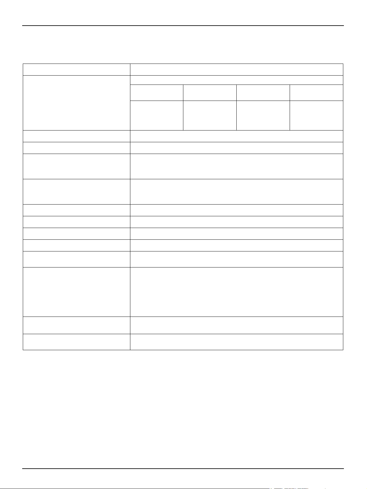
Section 1 Technical data
Table 1-1 FILTRAX
Supply: 230 V (option 115 V) ±10% AC, 50-60 Hz
Device with system components: 1500 VA
Cable Heater off
Power consumption:
Sample volume: approx. 900 ml/h for up to 3 process photometers
Head: Module carrier – control unit: 3 m ; control unit – process instrument: 7 m
2 m
10 m
20 m
30 m
150 VA
150 VA
150 VA
150 VA
Max. (-20° C)
start-up
450 VA
950 VA
1500 VA
2100 VA
Cont. (-20° C)
< 200 VA
< 300 VA
< 400 VA
< 500 VA
Outputs:
(use screened cable!)
Cable length:
User maintenance: approx. 1h / month
Medium temperature: +5° C to +40° C
Ambient temperature -20° C to +40° C
Enclosure rating: IP 55
Fuses:
Mass:
Dimensions:
Certification:
Fault signalling contact: floating contact (230 V, max. 3 A)
Warning contact: floating contact (230 V, max. 3 A)
Service interface: RS 232
Suction tube: 5 m (heated)
Sample tube: 2 m (unheated)
Sample tube: 10 m (heated), 20 m (heated), 30 m (heated)
T 4A E; 250V (2 ×)
T 7A E; 250V (2 ×)
Control unit: approx. 22 kg
Module carrier with 5 m suction tube: approx. 9 kg
Sample tube 10 m: approx. 5 kg
Sample tube 20 m: approx. 10 kg
Sample tube 30 m: approx. 15 kg
Mounting pipe 2 m: approx. 5 kg
Control unit (W x H x D): 430 x 530 x 220 mm
Module carrier (W x H x D): 92 x 500 x 340 mm
CE. The manufacturer clarifies conformity with the applicable EU safety guidelines
and EMC guidelines.
Subject to change without notice.
3
Page 6

Technical data
4
Page 7
Section 2 General information
2.1 Safety information
Please read this entire manual before unpacking, setting up or operating this
equipment. Pay attention to all danger, warning and caution statements. Failure to
do so could result in serious injury to the operator or damage to the equipment.
Make sure that the protection provided by this equipment is not impaired, do not
use or install this equipment in any manner other than that specified in this
manual.
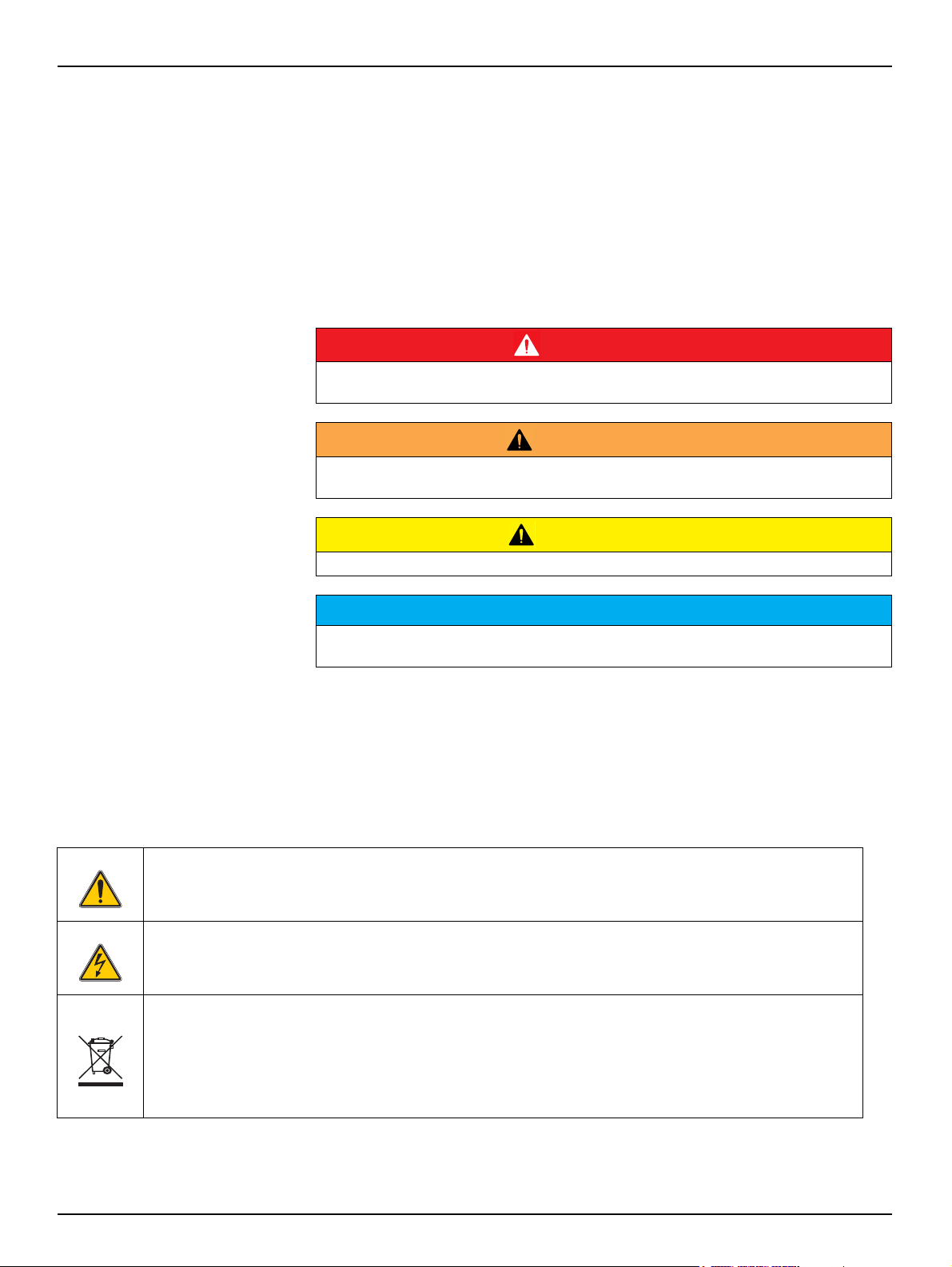
2.1.1 Use of hazard information
Indicates a potentially or imminently hazardous situation which, if not avoided, will result
in death or serious injury.
Indicates a potentially or imminently hazardous situation which, if not avoided, could
result in death or serious injury.
Indicates a potentially hazardous situation that may result in minor or moderate injury.
Indicates a situation which, if not avoided, may cause damage to the instrument.
Information that requires special emphasis.
Note: Information that supplements points in the main text.
2.1.2 Precautionary labels
DANGER
WARNING
CAUTION
NOTICE
Read all labels and tags attached to the instrument. Personal injury or damage to
the instrument could occur if not observed. A symbol on the instrument is
referenced in the manual with a precautionary statement.
This is the safety alert symbol. Obey all safety messages that follow this symbol to avoid potential injury. If on
the instrument, refer to the instruction manual for operation or safety information.
This symbol indicates that a risk of electrical shock and/or electrocution exists.
Electrical equipment marked with this symbol may not be disposed of in European domestic or public disposal
systems after 12 August 2005. In conformity with European local and national regulations (EU Directive
2002/96/EC), European electrical equipment users must now return old or end-of life equipment to the
manufacturer for disposal at no charge to the user..
Note: For return for recycling, please contact the equipment producer or supplier for instructions on how to
returnend-oflife equipment, producer-supplied electrical accessories, and all auxiliary items for proper disposal.
5
Page 8
General information
2.2 Applications
The FILTRAX sampling system is a device for the filtration and pumping of waste
water samples from the activated sludge tank or final clarification tank for
supplying process instruments with samples free of solids.
Any use other than use in accordance with requirements defined in the user manual
leads to the loss of the warranty claims and can lead to personal injury and property
damage, for which the manufacturer assumes no liability.
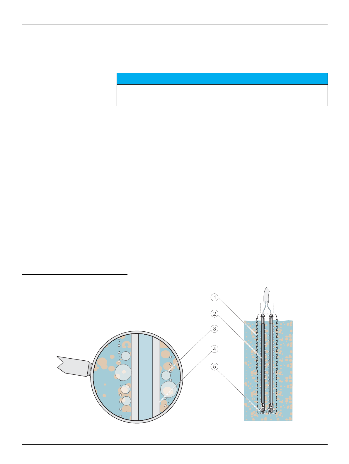
2.3 Functional description
The FILTRAX sampling and sample conditioning system comprises two
components: a control unit and module carrier.
The module carrier (1) is immersed at the place the samples are to be taken using
a special tank edge fastening. Inside the module carrier there are two filter
modules (2); a filter membrane (3) is stretched over both sides of each of the
modules. The waste water sample is fed to a special duct system (4) via this
membrane.
NOTICE
Two tube metering pumps inside the control unit draw the sample alternately from
the two filter modules using a common 5 m long heated suction tube to the control
unit that is installed in close proximity to the sampling point. From there the
sample is pumped 2 m, 10 m, 20 m or 30 m, depending on the sample tube
connected, to the process instruments.
A venting device (5) underneath the filter modules largely prevents the adhesion
of solids to the filter membranes and significantly reduces the maintenance effort.
Two signal lamps (green and red) provide continuous visual indication of normal
operation, warnings and faults - this information is also provided electrically by two
floating relay contacts.
Fig. 2-1 Layout of the filter modules
6
Page 9
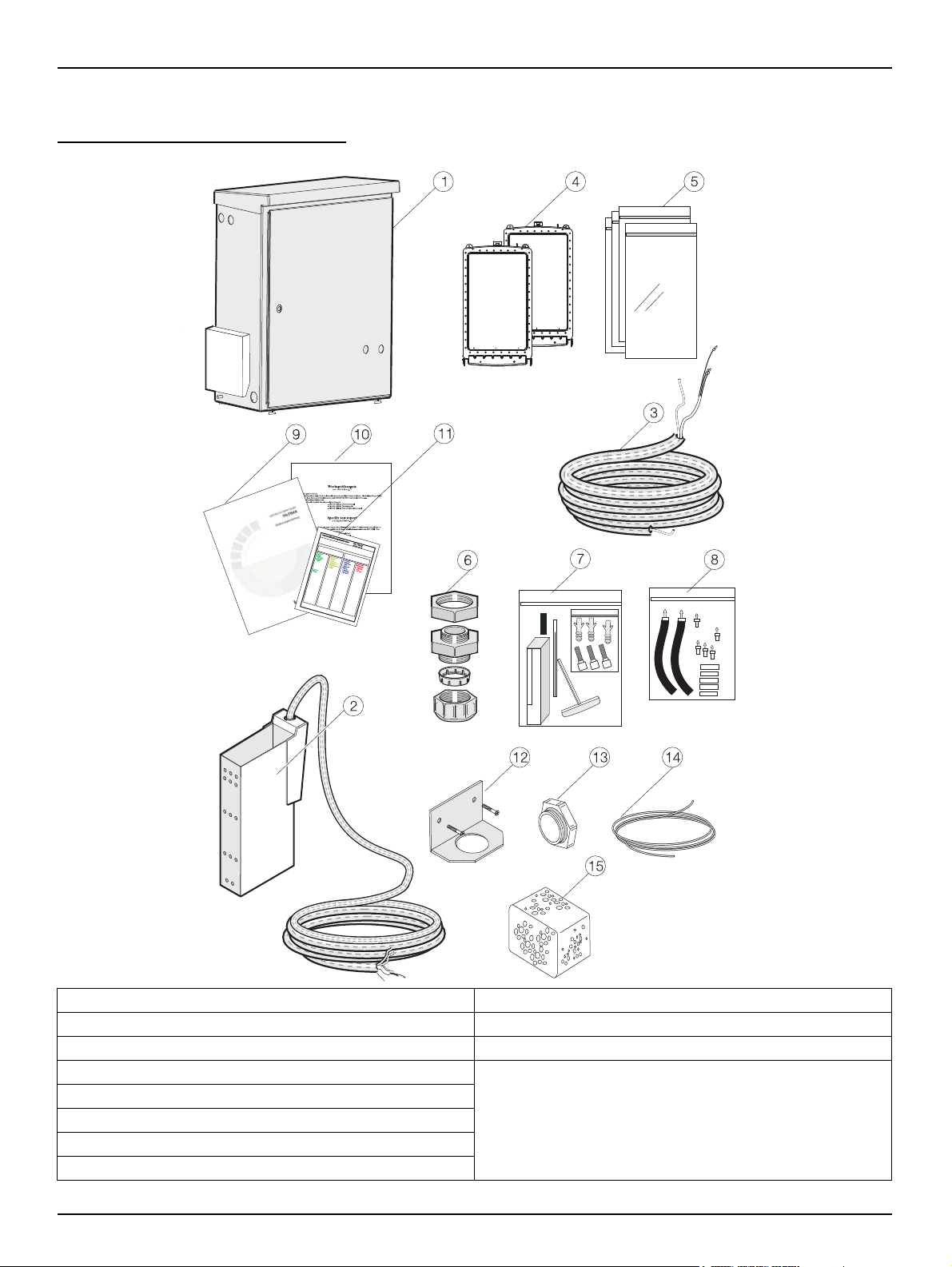
2.4 Items supplied
Fig. 2-2 Items supplied
General information
1. Control unit 9. Operating instructions
2. LZX670 (230 V) module carrier with 5 m suction tube 10. Factory test certificate
3. Sample tube 2 m, 10 m, 20 m, 30 m 11. DOC273.xx.04006 Maintenance calendar
4. LZX677 Filter module (2)
5. EYV017 Plastic bag for filter module (4)
6. Cable gland M20 x 1.5 (2)
7. LZX702 Accessory set
8. LZX701 Tube adapter set
Included in accessory set LZX702
12. Mounting bracket for sample tube
13. Blanking plugs (2) + sealing rings (2)
14. HLS191 2/4 tube 6 m
15. Cleaning sponge
16. Clip
7
Page 10
General information
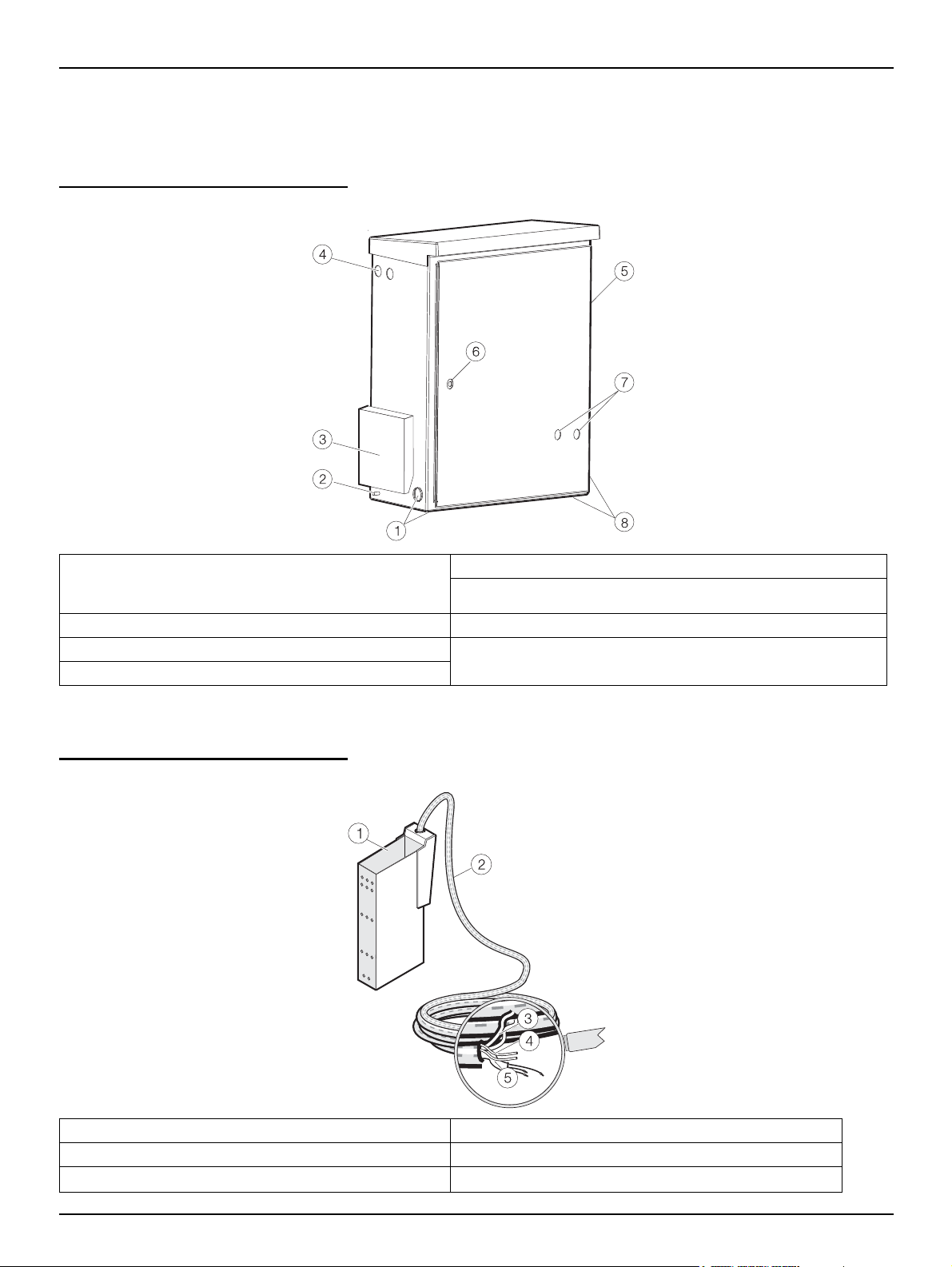
2.5 Instrument layout
2.5.1 Control unit
Fig. 2-3 Control unit
1. Suction tube connection (left or underneath on the left)
(Blanking plugs and sealing ring for the unused
opening)
2. Connection for equipotential bonding 7. Green and red signal lamps
3. Air filter cover (air inlet) 8. Sample tube connection (right or underneath on the right)
4. Cable gland for electrical connecting cable (2)
5. Air filter cover (air outlet)
6. Door lock
(Blanking plugs and sealing ring for the unused opening)
2.5.2 Module carrier
Fig. 2-4 Module carrier
1. Module carrier 4. Sample suction tube 3.2 mm OD (2)
2. Suction tube 5 m 5. Connecting cable for the tube heater
3. Air tube 6 mm OD (2)
8
Page 11
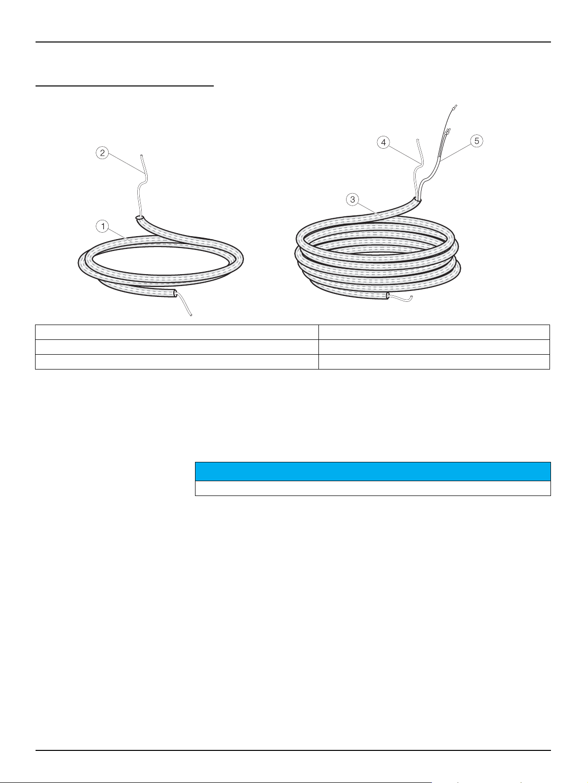
2.5.3 Sample tubes
Fig. 2-5 Sample tubes
General information
1. Sample tube 2 m, 23 mm (0.91 inch), not heated 4. Sample pressure tube 3.2 mm OD
2. Sample pressure tube 3.2 mm OD 5. Connecting cable for the tube heater
3. Sample tube 10 m, 20 m, 30 m, 23 mm (0.91 inch), heated
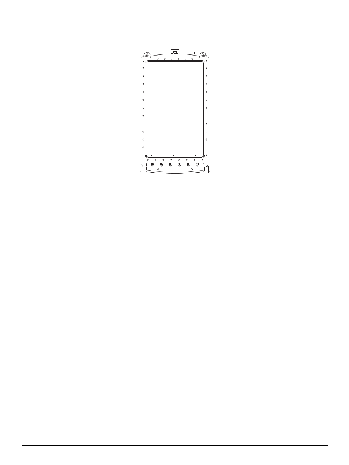
2.5.4 Filter modules
The two filter modules should only be installed during commissioning. Once
moistened, the filter membranes must not be allowed to dry out again and are
sealed in a plastic bag for protection.
NOTICE
The surface of the membrane is very delicate!
9
Page 12
General information
Fig. 2-6 Filter module
10
Page 13
Section 3 Installation
Only qualified experts should conduct the tasks described in this section.
Select an appropriate installation location for the instrument.
Plan out the mechanical mount before positioning poles or drilling holes. Make sure the
mount has a sufficient bearing capacity. The dowels must be selected and authorized
according to the condition of the wall.
The manufacturer shall accept no liability if the instrument is installed incorrectly.
Plan how to lay cables and tubes and their path in advance. Lay the tubes, data cables
and power cables without any bends and so they do not pose a tripping risk.
Do not connect the electrical supply to the mains until the instrument is completely wired
and protected against short circuits.
Sufficiently protect the electrical power supply against short circuits.
For the external power supply, always connect a residual-current circuit breaker (trip
current max.: 30 mA) between the mains and the system.
If the instrument is to be installed outdoors, connect a surge arrester between the mains
and the system.
Products intended by the manufacturer for outdoor use offer a higher level of protection
against the penetration of liquids and dust. If these products are connected to a mains
outlet with a cable and plug rather than a permanently connected cable, the plug and
outlet are much more susceptible to liquid and dust penetration. The operator must
sufficiently protect the plug and outlet against liquid and dust penetration in accordance
with local safety regulations. If the instrument is to be used outdoors, it must be
connected to a suitable outlet with a protection type of at least IP44 (splash protection).
DANGER
DANGER
WARNING
Electrical dangers and fire hazard. Use only the supplied power cable.
Only qualified experts may perform the tasks described in this section of the manual, in
compliance with all locally applicable safety regulations.
NOTICE
Protect the device against extreme temperatures from heaters, direct sunlight and other
heat sources.
CAUTION
Note the weight (control unit approx. 22 kg, module carrier with 5 m suction tube approx.
9 kg) of the instrument. Do not try to carry the instrument without help. Use only suitable
lifting devices for the transport.
11
Page 14
Installation
aaaa
aaaa
aaaa
aaaaaaa
aaaaaaa
aaaaaaa
aaaaaaa
aaaaaaa
aaaaaaa
aaaaaaa
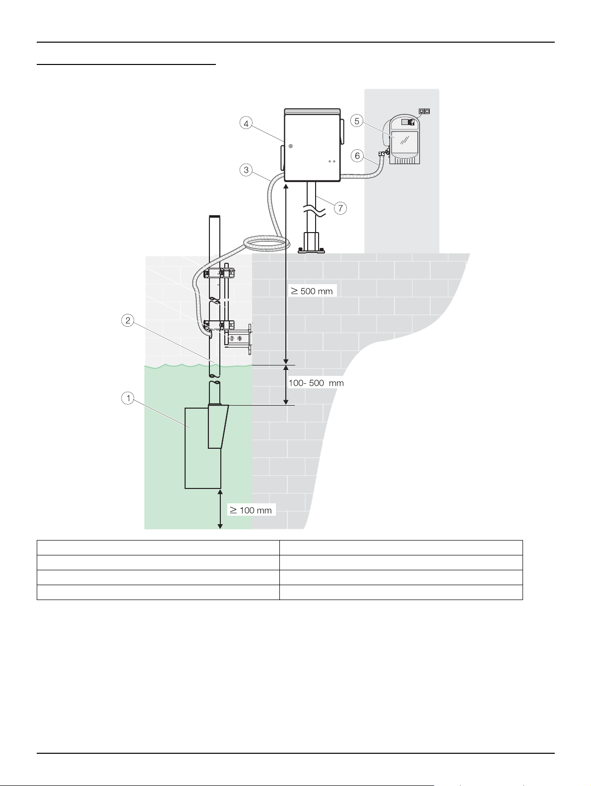
Fig. 3-7 Installation overview
1. Module carrier 5. Process instrument
2. Bracket FILTRAX module carrier (option) 6. Sample tube
3. Suction tube 5 m 7. Bracket FILTRAX control unit (option)
4. Control unit
12
Page 15
3.1 Mechanical installation
Select an appropriate installation location for the instrument.
Plan out the mechanical mount before positioning poles or drilling holes. Make sure the
mount has a sufficient bearing capacity. The dowels must be selected and authorized
according to the condition of the wall.
The manufacturer shall accept no liability if the instrument is installed incorrectly.
Plan how to lay cables and tubes and their path in advance.
Lay the tubes, data cables and power cables without any bends and so they do not pose
a tripping risk.
For information on installation with optional accessories, refer to the relevant installation
instructions.
The filter module should only be unpacked directly before commissioning and quickly
attached to the module carrier.
The filter membranes are shrink-wrapped in protective plastic; once they have been
moistened they must not be allowed to dry out.
Installation
DANGER
NOTICE
NOTICE
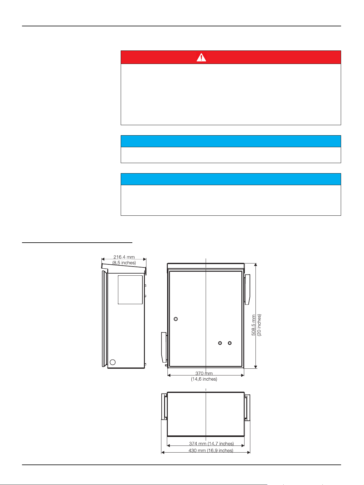
3.1.1 Dimensions
Fig. 3-8 Control unit
13
Page 16
Installation
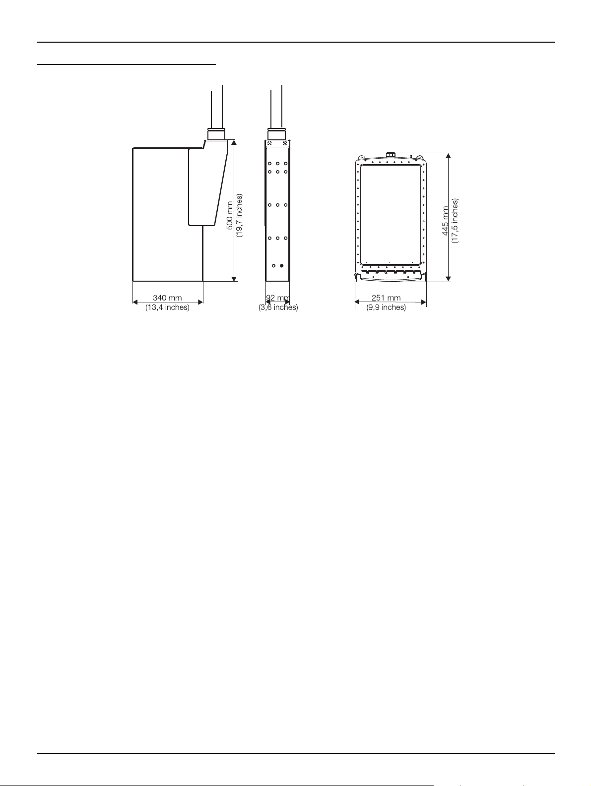
Fig. 3-9 Module carrier and filter module
14
Page 17
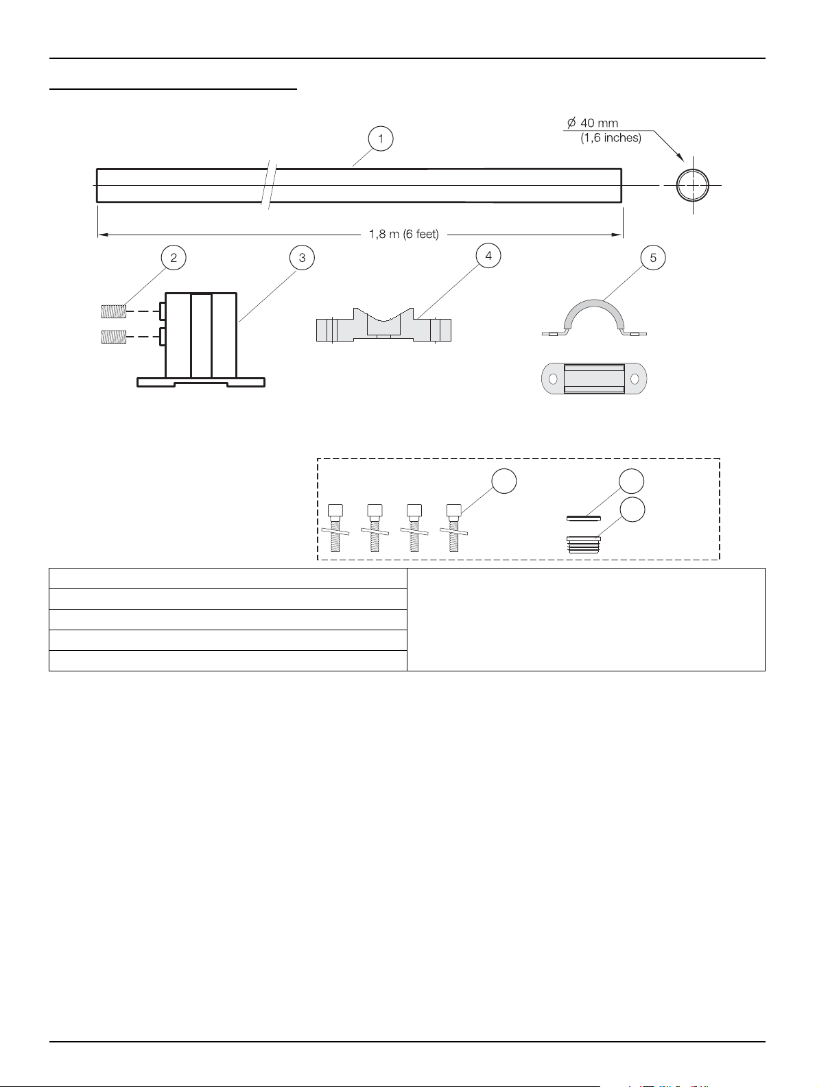
Fig. 3-10 Control unit bracket components
Installation
1. HRO304 supporting pipe 1.8 m
2. Setscrew M8 x 10 (2) in LZX416
3. ATS010 base
4. HHH277 bracket (2)
5. EHK063 pipe clamp (2)
6
Included in hardware LZX416:
6. Cheese head bolt M8 x 16 (4)
7. Blanking plug
8. Plug
7
8
15
Page 18
Installation
aaaa
aaaa
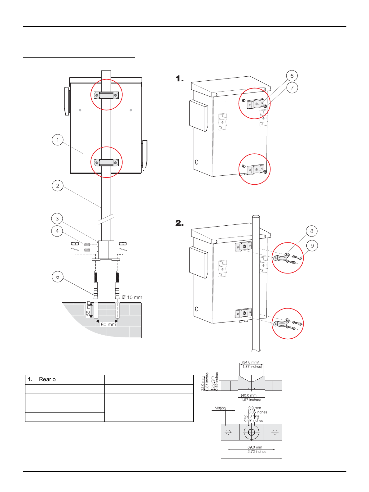
1. Rear of control unit 6. Bracket (2)
2. Supporting pipe 1.8 m 7. Nut M8 (2)
3. Base 8. Pipe clamp (2)
4. Setscrew M8 x 10 (2) 9. Cheese head bolt M8 x 16 (2)
+ washer (2)
5. Anchor (4)
3.2 Installing control unit with control unit bracket LZX676
Fig. 3-11 Installation of control unit bracket
16
Page 19

Fig. 3-12 Installation on a wall (hole diagram)
Procedure:
1. Make the two upper holes.
2. Use wall plugs and screws from the accessory set.
3. Fit instrument.
4. Mark third hole at the bottom and make hole.
5. Fit instrument.
At least
300 mm
Installation
17
Page 20

Installation
Fig. 3-13 Components for the module carrier bracket
1. (a) BRO060 mounting pipe 2.0 m for LZX414.00.00000
(b) BRO069 mounting pipe 2.0 m with slot on side for
LZX414.00.40000
Included in retaining clamp LZX200:
2. Clamp half (2)
3. Cheese head bolt M5 x 20 (6)
4. Clamp half with thread (2)
5. ATS010 base
6
5
6. HPL061 fastening lug
Included in hardware LZX416:
7. Cheese head bolt M8 x 40
8. Blanking plug
9. Plug
Included in hardware LZX417:
10. Flat seal
Included in hardware LZX702:
11. Cheese head bolt M3 x 10 (6)
8
9
10
11
7
18
Page 21

Fig. 3-14 Installation of module carrier
aa
aa
aa
Installation
1. Base 7. Fastening lug
2. Anchor (4) 8. Cheese head bolt M8 x 40
3. Blanking plug 9. Cheese head bolt M3 x 10 (6)
4. Plug 10. Flat seal
5. Mounting pipe 2.0 m for LZX414.00.00000 or mounting
pipe 2.0 m with slot on side for LZX414.00.40000
6. Retaining clamp
11. Module carrier
19
Page 22

Installation
3.3 Connecting tubes
Fig. 3-15 Preparation of suction tube connection
1. Protective tube (transport protection) 4. Cable gland M20 x 1.5
2. Shrink tube 5. Suction tube
3. Metal sleeve 6. Blanking plug
20
Page 23

Fig. 3-16 Preparation of sample tube connection
Installation
1. Protective tube (transport protection) 4. Cable gland M20 x 1.5
2. Shrink tube 5. Suction tube
3. Metal sleeve 6. Blanking plug
21
Page 24

Installation
Fig. 3-17 Layout of suction tube
1. Suction tube 4. Air tubes
2. Pipe heater connecting cable 5. Clip
3. Sample suction tubes
NOTICE
The tubes must be laid with the aid of the clips such that they cannot chaff due to the
vibration from the compressor!
22
Page 25

Fig. 3-18 Laying sample tube
Installation
Note: the sample pressure tube (1) is pushed through the flowmeter from below and
fastened to the 90° fitting (3). The fixing screw (2) is then tightened lightly.
1. Sample pressure tube 4. Pipe heater connecting cable
2. Fixing screw 5. Sample tube
3. 90° fitting
23
Page 26

Installation
Fig. 3-19 Tube diagram
Note: always ensure that the tubes are laid correctly! The filter modules may be damaged
if sample is pumped back via the sample suction tubes (1)+(2)!
1. Sample suction tube, filter module A or B 4. Pump cartridges
2. Sample suction tube, filter module A or B 5. Metering tube
3. Connecting tube 6. Sample pressure tube
24
Page 27

3.4 Electrical connections
Use only earthed sockets for the connection of this device to the power supply.
If it is not clear whether the sockets are earthed, have this checked by a qualified
electrician.
In addition to supplying power, the power plug also serves to isolate the device quickly
from the mains where necessary.
The entire measurement system has two power plugs (measurement device and control
unit). During the disconnection from the mains, it must be made sure that the correct
power plug is pulled (e.g. labeling of the sockets).
This is recommended for long-term disuse and can prevent potential dangers in the
event of a fault.
Therefore make sure that the sockets to which the device is connected are easy to
reach by each user at all times.
On removal of the power plug (fixed installation of mains supply lead), a suitable bipolar
circuit breaker must be installed!
Installation
NOTICE
NOTICE
NOTICE
Pull out the power plug before opening the device.
WARNING
Only qualified experts may perform the tasks described in this section of the manual, in
compliance with all locally applicable safety regulations.
25
Page 28

Installation
Fig. 3-20 Terminal assignments
Sicherungen/Fuses
250 V
IEC
F1:
F2:
F3:
F4:
T3,15A L
T3,15A L
T6, 3A L
T6, 3A L
UL
T4A E
T4A E
T7A E
T7A E
1. Mains cable (power supply) 3. Heater connecting cable, sample tube
2. Earth connection 4. Heater connecting cable, suction tube
NOTICE
Route the signal lines (21, 22, 23, 24) separated from the power cable.
Table 3-1 Terminal assignments
Terminal no. Connection
1 N (230 V AC / 50-60 Hz, option: 115 V AC)
2 L (230 V AC / 50-60 Hz, option: 115 V AC)
7 N (sample tube heater)
8 N (suction tube heater)
9 L (sample tube heater)
10 L (suction tube heater)
18 Earth for screening signal wires
19 Earth for suction tube heater
20 Earth for sample tube heater
21/22 Floating fault signalling contacts (normally open)
23/24 Floating warning contacts (normally open)
26
Page 29

3.5 Connection to process instruments
The filtered sample passes through the sample pressure tube inside the sample
tube to the process instruments connected.
The bracket enables the sample tube to be fastened to a wall at a distance of
approx. 200 mm from the process instrument.
Fig. 3-21 Mounting bracket
Installation
1. Sample pressure tube 3. Cable gland M20 x 1.5
2. Bracket 4. Sample tube
27
Page 30

Installation
All the adapters necessary to the direct connection of the sample
pressure tube to the sample feed openings on the process instruments
are supplied in the tube adapter set LZX701 supplied.
If several instruments are supplied from one FILTRAX, the sample must
be provided from the first instrument to the next using the 2/4 tube to
ensure a short time delay.
Fig. 3-22 Connection of sample pressure tube
1. FILTRAX sample pressure tube 5. 4/6 tube
2. Sleeve 6. 2/4 tube
3. Quick-release connector 7. Small fitting
4. Large fitting
28
Page 31

Installation
29
Page 32

Section 4 Commissioning
4.1 Placing instrument in operation
NOTICE
The sample pressure tube must never be clamped such that it is blocked off - the
pressure build up would either result in damage to the tubes or the tube connections
would spring off!!
After assembly has been completed, you can place FILTRAX in operation.
For this purpose
1. Clip pump cartridges into the control unit
2. Unpack the two filter modules and carefully slide into the module carrier!
NOTICE
As far as possible do not touch the delicate filter membrane!
3. Fit the two thicker sample tubes and the two thinner air tubes to tube fittings of
appropriate size as per the figure
4. Plug into the mains and set instrument parameters (sec. 5 Software menu
system)
30
Page 33

Fig. 4-23 Inserting filter modules
Commissioning
31
Page 34

Commissioning
Menu
NO SAMPLE!
INTERVAL
PREPUMP
PREPUMP
4.2 Taking instrument out of operation
4.2.1 Filter modules
If the instrument is to be taken out of operation for an extended period, you should
clean the filter modules (sec. 6 Maintenance) and then protect against drying out.
For this purpose 4 plastic bags are supplied.
Fig. 4-24 Plastic bag
4.2.2 Control unit
On installation outdoors, the control unit should always be in operation so that the
temperature control can provide protection against overheating or freezing. When
the instrument is taken out of operation, the [+SERVICE] menu is opened or the
control unit removed:
• Prior to dismantling open the [+SERVICE] menu and remove suction and
sample tube
• Select [PREPUMP] command and leave the internal tubes to empty
• Then open [+SERVICE] menu again, release tension on pump cartridges
and unplug from the mains
32
Page 35

Commissioning
33
Page 36

Section 5 Operation
5.1 Using the keypad
All functions in the instrument are software-controlled. Operation is via menus
using the four keys below the display. The current sample volumes (1) for the two
filter modules and the operating state of the heating (2) can be seen on the
display during operation. To reach the menu level of the program, one of the four
function keys F1-F4 (3) must be pressed for 3 seconds.
The significance of the keys on the menus appears (sensibly abbreviated) in the
second line on the display (softkey function):
= Cancel
= Change the setting
= Back to the previous command
= Continue to the next command
Fig. 5-25 Display
1. Current sample volume (approx. ml/h) 3. Function keys
2. Operating state of the heating, alternatively:
messages, warnings, faults
34
Page 37

5.2 Menu overview
Menu level 1 Menu level 2
Operation
+DEVICEDATA
For setting the instrument parameters
+SIGNALS
For checking internal data in case of
service
CONTRAST
LANGUAGE
HEATER
HEAT.START
HEAT.STOP
WARNING<
FAULT<
DATE
TIME
PASSWORD
SW-VERSION
SW-CO.PROC.
MODUL A
MODUL B
TEMPERATURE (control unit)
AMPL.
MEAS-Z
MEAS
MEAS-F
+SERVICE
For maintenance and function tests
+OP.COUNTERS
(display only)
INTERVAL
EXTRACTION
PREPUMP
FILTERCLEANING
+OP.COUNTERS (display and reset)
+TEST OF FUNCT.
+SIGNALS
+DEVICEDATA
STATUS (output of detailed error messages and
acknowledgement)
CLEANED
MODUL A
MODUL B
PUMPTUBES
PUMPCASSETTES
PUMPWHEELS
AIRFILTER COMPRESSOR
AIRFILTER CASE
COMPRESSOR
35
Page 38

Operation
5.3 [+DEVICEDATA] menu
Instrument parameters for adaptation to the related conditions.
Note: While the instrument is in this menu, sample pumping continues. If a key is not
pressed for longer than ten minutes, the instrument automatically returns to the display of
the data on operation.
MENU
Command
Setting Description
+DEVICEDATA
CONTRAST
-90 to +90 Reading angle for the display
LANGUAGE
D, GB, NL, F, I, E, PL, S
HEATER
ON, OFF, TIMER (time control)
Default setting: TIMER
HEAT.START (only for [HEATER]:TIMER)
JAN to DEC,
Default setting: OCT
HEAT.STOP (only for [HEATER]:TIMER)
JAN to DEC,
Default setting: MRZ (March)
WARNING<
Operation of the tube heaters
Activation of the heater at the start of the month selected
Deactivation of the heater at the end of the month selected
200...800 ml/h in 10 ml steps
FAULT<
100...600 ml/h in 10 ml steps
DATE
Setting for the date
TIME
Setting for the time
PASSWORD
4-digits with numbers 1-4 Password protection on activation
SW-VERSION
Only for information Version of the instrument software
SW-CO.PROC.
Only for information Version of the coprocessor software
Warning relay contact* set when the sample volume drops below
the amount set
Fault relay contact* set when the sample volume drops below the
amount set
*If the power supply is interrupted (power failure) both relay contacts are closed.
36
Page 39

5.4 [+SIGNALS] menu
MENU
Command
Description
+SIGNALS
MODUL A
Parameter for the flow rate in module A (single measurement),
approximately corresponds to a sample volume in ml/h
MODUL B
Parameter for the flow rate in module B (single measurement),
approximately corresponds to a sample volume in ml/h
TEMPERATURE (housing)
Temperature in the control unit in °C or °F
AMPL.
Photometer gain
Operation
The [+SIGNALS] menu is used for service and inspection by the manufacturer. It
is not needed for operation and the instrument settings.
Note: While the instrument is in this menu, normal operation continues. If a key is not
pressed for longer than ten minutes, the display automatically returns to the display of the
data on operation.
MEAS-Z
MEAS
MEAS-F
Level of the last valid zero measurement
Level of the last valid flow rate measurement
Current measured level
37
Page 40

Operation
5.5 [+OP.COUNTERS] menu
The [+OP.COUNTERS] menu provides information on the duration of the use of
the various instrument components and consumables. It is not needed for
operation and the instrument settings.
Note: While the instrument is in this menu, normal operation continues. If a key is not
pressed for longer than ten minutes, the display automatically returns to the display of the
data on operation.
MENU
Command
Description
+OP.COUNTERS
CLEANED
Month when cleaning was last performed, is automatically updated during [+FILTERCLEANING]
MODUL A
Operating time for filter module A in days
MODUL B
Operating time for filter module B in days
P.TUBES IN
Remaining operating time for both pump tubes in days (91 - 0 - negative number*)
P.CARTR.IN
Remaining operating time for both pump cartridges in days (365 - 0 - negative number*)
P.ROLL.IN
Remaining operating time for pump rollers in days (365 - 0 - negative number*)
AIR F.C.IN
Remaining operating time for the compressor air filter in days (365 - 0 - negative number*)
AIR F.H.IN
Remaining operating time for the two air filters in the control unit in days (91 - 0 - negative number*) - it is not
necessarily imperative to change the air filter on the air outlet side so frequently
COMP. IN
Remaining operating time for the compressor in days (730 - 0 - negative number*)
*If replacement date passed.
38
Page 41

5.6 [+SERVICE] menu
Operation
Important Note: All maintenance and service work apart from pure visual inspection must
be performed with the instrument in this menu!
When this menu is opened,
initially the message "OK - NO
SAMPLE!" appears to indicate
that on the activation of this
menu, sample feed to the
measuring instruments is
interrupted immediately!
Operation is only re-started
when this menu is actively left
using the keypad or a program
that is opened.
MENU
Command
Setting Description
+SERVICE
INTERVAL
30...300 s (default setting 60 s)
EXTRACTION
50...130% (default setting 100% = 900 ml/h this sample volume is produced on correct
installation under normal operating conditions
with clean filter modules)
PREPUMP
FILTERCLEANING
PHOTOMETER
ON/OFF Flow rate measurement can be switched on and off
If this menu is selected, then
• The pumps are stopped immediately
• The filter module venting is shut down
• The red signal lamp is illuminated
• The fault relay is set
• Only the temperature control and heater systems in the control unit and
the tubes remain active
The functions of the individual commands and sub-menus ([FILTERCLEANING],
[OP.COUNTERS], [+TEST OF FUNCT.]) are explained in detail in section 6
Maintenance and section 7 Faults, causes, rectification. They are not required for
normal operation.
Changeover interval for sample pumping between module A
and B
The volume pumped by the pumps is adjusted via the speed of
the pumps
For filling all tubes both pumps are operated simultaneously for
10 min.
The venting of the filter modules remains active - operation is
then re-started automatically
Menu-based cleaning of the filter modules, detailed description
in sec. 7.2 Maintenance - after each clean the date of the
operating counter [CLEANED] is automatically updated and
operation re-started
39
Page 42

Operation
MENU
Submenu
+SERVICE
+OP.COUNTERS
+TEST OF FUNCT.
Command Description
Open [+OP.COUNTERS] menu - all counters can now be
reset
Component Possible selections
compressor on, off
pump a (back and forward every 3 s), stop
pump b (back and forward every 3 s), stop
housing fan on, off
hous. heater on, off
heater tubes on, off
warning on, off
malfunction on, off
sensor a volume measurement a
sensor b volume measurement b
airvalve a op., cl.
airvalve b op., cl.
signallamps on, off (green/red simultaneously)
Every component listed can be operated and tested
individually
+SIGNALS
+DEVICEDATA
STATUS
Open [+SIGNALS] menu
Open [+DEVICEDATA] menu
Detailed fault description and acknowledgement
40
Page 43

Operation
41
Page 44

Section 6 Maintenance
Every 24 months
Replace
w Compressor
Weekly
Visual Inspection
w Sample Quality
w Device Function
w Air Filter
(Control Unit)
Every 3 months
Replace
w Pump Tubes
w Air Filter
(Control Unit)
Clean
w Filter Module
(if/as necessary)
w Sample Tubes
(if/as necessary)
Every 6 months
Check
w Air Filter
(Compressor)
w Pump Cartridges
w Pump Rollers
w Connecting Tubes
w Filter Module
w Elektronics
Every 12 months
Every 12 months
Replace Replace
w Air Filter w Air Filter
(Compressor) (Compressor)
w Pump Cartridges w Pump Cartridges
w Pump Rollers w Pump Rollers
w Connecting Tubes w Connecting Tubes
Number:
Place of sampling:
Installation Date: by:
Inspection and Maintenance as part of the
Service Contract
Maintenance by the
User
DOC273.52.04006.Jul03
FILTRAX
Maintenance Schedule
The manufacturer recommends taking out a service contract. This contract
extends the warranty to 5 years and ensures that all inspection and maintenance
work is performed by qualified personnel.
The maintenance to be performed by the user is then limited to regular visual
inspections, replacing consumables and cleaning, if necessary.
6.1 Maintenance work
The reliable and correct operation of this sample conditioning system can only be
ensured if the maintenance work is performed regularly as per the maintenance
calendar.
The necessary consumables are supplied or included in the set of annual
consumables.
The sample pressure tube must never be clamped such that it is blocked off - the
pressure build up would either result in damage to the tubes or the tube connections
would spring off!!
NOTICE
42
Page 45

6.1.1 Weekly
6.1.2 Every 3 months
Maintenance
Visual inspection
• General instrument function
• Function of the venting on the filter modules
• Quality of the filtered samples
• State of the air filter in the control unit
All maintenance work must
be performed in the [+SERVICE]
menu!
Fig. 6-26 Consumables after 3 months
Replacement of consumables and cleaning
• Replacement of the metering tubes
• Replacement of control unit air filter
(depending on condition only air inlet)
• Menu-based cleaning
(this cleaning interval can vary depending on the conditions)
Fig. 6-27 Metering tube replacement
43
Page 46

Maintenance
6.1.3 Every 12 or 24 months
Fig. 6-28
As part of the service contract by customer service:
after 12 months
• Replacement of the metering tubes together with the connecting tubes
• Replacement of the pump cartridges and pump rollers
• Replacement of compressor air filter
after 24 months
• Replacement of compressor
44
Page 47

6.1.4 Menu-based cleaning
Maintenance
DANGER
Potential danger with contact with chemical/biological substances.
Working with chemical samples, standards and reagents can be dangerous.
Make yourself familiar with the necessary safety procedures and the correct handling of
the chemicals before use and read and follow all relevant safety data sheets.
Normal operation of this device may require the use of samples that are
biologically unsafe.
WARNING
Observe all cautionary information printed on the original solution containers and safety
data sheets prior to their use.
Dispose of all consumed solutions in accordance with the local and national regulations
and laws.
Select the type of protective equipment suitable to the concentration and quantity of the
dangerous material being used.
Observe instructions and safety information (information on risks and safety) on the
containers for the chemicals used.
Wear safety clothing: Lab coat, Safety glasses, Rubber gloves
Action FILTRAX display
1. On all process instruments connected and on the FILTRAX open the [+SERVICE]
menu, then the [+FILTERCLEANING] menu.
2. Lift the module carrier out of the tank or flume and acknowledge with [ok].
3. Pull off the air and sample tubes connected to the module carrier, carefully pull out
the filter modules and acknowledge with [ok].
NOTICE
As far as possible do not touch the delicate membranes and never allow the membranes
to dry out, if necessary store the filter modules in the plastic bags supplied!
4. Carefully clean the filter modules using 5% chlorine bleach (sodium hypochloride) or
5% hydrochloric acid (for high iron concentrations) and a soft sponge, during this
process do not soil the air and sample suction pipe!
WARNING
Observe the safety precautions when handling the cleaning solution and wear
appropriate safety clothing!
The chlorine bleach must not come into contact with reagents containing acids, chlorine
gas will be formed!
5. After leaving to soak for 10 minutes, slide the filter modules directly back into the
module carrier, without prior rinsing with water, so that the sample tubes are cleaned
with the solution left in the filter - acknowledge cleaning with [ok].
6. Immerse module carrier again and acknowledge with [ok].
+FILTERCLEANING
NO SAMPLE!
REM.MOD.CARRIER
REMOVE MODUL
CLEAN MODUL
CLEAN MODUL
REPLACE MODUL
7. Activate cleaning of the sample pipes with the [PREPUMP] function
(600 seconds - counter counts backwards, the date for the operating time counter
[CLEANED] is now updated automatically).
After completion of the prepumping program, place all instruments connected back in
operation.
PREPUMP 600 s
45
Page 48

Maintenance
6.1.5 Cleaning with cleaning container (option)
Action FILTRAX display
1. On all process instruments connected and on the FILTRAX open the [+SERVICE]
menu to prevent the process instruments drawing in cleaning solution. Choose the
[+FILTERCLEANING] menu.
2. Lift the module carrier out of the tank or flume and accept with [ok].
3. Pull off the air and sample tubes connected to the module carrier, carefully pull out
the filter modules and acknowledge with [ok].
NOTICE
As far as possible do not touch the delicate membranes and never allow the membranes
to dry out.
4. Slide the filter modules into the cleaning container. Lay tubes as per diagram.
5. Carefully fill the cleaning container with 5% chlorine bleach (sodium hypochloride)!
WARNING
Observe the safety precautions when handling the cleaning solution and wear
appropriate safety clothing!
The chlorine bleach must not come into contact with reagents containing acids, chlorine
gas will be formed!
6. Soaking time: 10 minutes, then acknowledge with [ok]. Further clean or clean
mechanically in case of heavy soiling.
7. Activate the cleaning of the sample pipes using the [PREPUMP] function (counter
counts backwards from 600 s, the date for the operating time counter [CLEANED] is
now updated automatically).
8. Slide the filter modules back into the module carrier and immerse the module carrier
again at the location for the measurements.
[+FILTERCLEANING], NO SAMPLE
REM.MOD.CARRIER
REMOVE MODUL
CLEAN MODUL
REPLACE MODUL
PREPUMP 600 s (count down to 0)
46
Page 49

Maintenance
9. Open the [+SERVICE] menu and then the [PREPUMP] function.
10. 10-15 minutes later place all instruments back in operation.
[+SERVICE]
PREPUMP 600 s (count down to 0)
47
Page 50

Maintenance
6.1.6 Cleaning with cleaning set (option)
Action Menu/acknowledge
1. On all process instruments connected and on the FILTRAX open the
[+SERVICE] menu to prevent the process instruments drawing in cleaning
solution. Choose the [+FILTERCLEANING] menu.
2. Lift the module carrier out of the tank or flume and accept 2 x with [ok].
3. Carefully fill the cleaning bottle with 5% chlorine bleach (sodium hypochloride)!
[+FILTERCLEANING], NO SAMPLE
REM.MOD.CARRIER
REMOVE MODUL
WARNING
Observe the safety precautions when handling the cleaning solution and wear
appropriate safety clothing!
The chlorine bleach must not come into contact with reagents containing acids,
chlorine gas will be formed!
4. Pull off the sample tubes connected to the module carrier and acknowledge with
[ok]. Lay tubes as per diagram.
5. Activate the cleaning of the sample pipes using the [PREPUMP] function
(counter counts down from 600 s, the date for the operating time counter
[CLEANED] is now updated automatically).
6. Lay the tubes for the filter modules as before and immerse the module carrier
again at the location for the measurements.
7. Open the [+SERVICE] menu and then the [PREPUMP] function.
8. 10-15 minutes later place all instruments back in operation.
CLEAN MODUL
PREPUMP 600 s (count down to 0)
[+SERVICE]
PREPUMP 600 s (count down to 0)
48
Page 51

Section 7 Faults, causes, rectification
Note: FILTRAX has three different types of error messages
7.1 Messages
Only text is displayed referring to the need for the
replacement of consumables - the green signal lamp
remains active.
FAULT CAUSE RECTIFICATION
AIRFILTER COMP.
AIRFILTER CASE
PUMPWHEELS
PUMPCASSETTE
COMPRESSOR
The operating time counter for the compressor air
filter [AIR F.C.] has expired
The operating time counter for the control unit air
filter [AIR F.H.] has expired
The operating time counter for the pump rollers
[P.ROLL] has expired
The operating time counter for the pump
cartridges [P.CARTR.] has expired
The operating time counter for the compressor
[COMP.] has expired
Replace compressor air filter and reset operating
time counter
Replace control unit air filter and reset operating time
counter
Replace pump rollers and reset operating time
counter
Replace pump cartridges and reset operating time
counter
Replace compressor and reset operating time
counter
7.2 Warnings
Text is displayed, both signal lamps are active and the
warning relay contact is set. If possible rectify without delay!
FAULT CAUSE RECTIFICATION
PUMPTUBES
LESS SAMPLE
TEMPERATURE
TEST SETTINGS
The operating time counter for the pump tubes
[P.TUBES] has expired
The amount of sample from a module is below the
threshold set under [WARNING < ]
The temperature in the control unit is too high, the
filter module venting is shut down automatically
On the [+DEVICEDATA] menu some settings may
have been lost
Replace pump tubes and reset operating time
counter
Check all tubes, if necessary clean filter modules
Check fans in the control unit, if necessary replace
filter mats, reduce ambient temperature
Check all instrument settings on the [+DEVICEDATA]
menu and [+SERVICE] menu
49
Page 52

Faults, causes, rectification
7.3 Faults
Text is displayed, the red signal lamp is active and the fault
relay contact is set. Action must be taken immediately!
FAULT CAUSE RECTIFICATION
FAULT
PHOTOMETER
WARM UP MODE!
FAULT SAMPLE
FAULT DEVICE
TEMP.SENSOR
Electronic fault or
no measurable sample flow rate (e.g. valve faulty,
air bubbles due to lack of sample)
The temperature in the housing is <1 °C, the
instrument is warming up
The amount of sample from a module is below the
threshold set under [FAULT < ]
Serious electronic fault / bus fault
Normal operation is no longer possible!!
Temperature sensor faulty or not fitted
Normal operation is stopped because it is no
longer possible to regulate the temperature!
7.4 Voltage drop (power failure)
On a power failure both relay contacts are closed (warning
and fault signalling).
Check sample flow rate, if necessary clean sample
pipe, call customer service
Wait until the heater has raised the temperature in
the housing to > 1° C, the warm up phase then takes
a further 30 min. Keep door closed!
Check all tubes and pumps, if necessary clean filter
modules and sample pipe
Unplug from the mains for 1 min, if the fault is still
present
Call customer service
Check connection to temperature sensor,
Call customer service
50
Page 53

Section 8 Spare parts
Baysilone paste ..............................................................................................................................................EZH051
Sample tube 2 m unheated ............................................................................................................................ LZX675
Sample tube 10 m heated 230 V .................................................................................................................... LZX672
Sample tube 10 m heated 115 V .................................................................................................................... LZX671
Sample tube 20 m heated 230 V .................................................................................................................... LZX674
Sample tube 20 m heated 115 V .................................................................................................................... LZX673
Sample tube 30 m heated 230 V .................................................................................................................... LZX675
Filter mat set (8 pieces) for control unit .......................................................................................................... LZX017
Filter module completely packaged ................................................................................................................ LZX677
Plastic bag for storing filter module ...............................................................................................................EYV017
Set of tubes for one year ............................................................................................................................... LZX667
Set of annual consumables ............................................................................................................................ LZX018
Compressor 115 V.......................................................................................................................................... LZX025
Compressor 230 V.......................................................................................................................................... LZX024
Module carrier complete with 5 m suction tube 230 V.................................................................................... LZX670
Module carrier complete with 5 m suction tube 115 V.................................................................................... LZX669
Sample connecting tube (external), 6m, 2/4 mm black ..................................................................................HLS191
Pump cartridge .............................................................................................................................................. LZP777
Pump rollers 2-channel (5 pieces).................................................................................................................. LZX019
Valve (2/2 way) ............................................................................................................................................... LZV205
Accessories
Tank edge fastening, module carrier .............................................................................................. LZX414.00.00000
Tank edge fastening, module carrier
Bracket for control unit.................................................................................................................................... LZX676
Tube adapter set for instruments connected in series ................................................................................... LZX701
Pipe clamps .................................................................................................................................................. EHK063
Second fastening point for mounting pipe (for long struts) ............................................................................. LZX456
Cleaning container.......................................................................................................................................... LZX216
Cleaning set.................................................................................................................................................... LZX217
(mounting pipe with slot on side) ............................................... LZX414.00.40000
51
Page 54

52
Page 55

Section 9 Warranty and liability
The manufacturer warrants that the product supplied is free of material and
manufacturing defects and undertakes the obligation to repair or replace any
defective parts at zero cost.
The warranty period for instruments is 24 months. If a service contract is taken out
within 6 months of purchase, the warranty period is extended to 60 months.
With the exclusion of the further claims, the supplier is liable for defects including
the lack of assured properties as follows: all those parts that, within the warranty
period calculated from the day of the transfer of risk, can be demonstrated to have
become unusable or that can only be used with significant limitations due to a
situation present prior to the transfer of risk, in particular due to incorrect design,
poor materials or inadequate finish will be improved or replaced, at the supplier's
discretion. The identification of such defects must be notified to the supplier in
writing without delay, however at the latest 7 days after the identification of the
fault. If the customer fails to notify the supplier, the product is considered
approved despite the defect. Further liability for any direct or indirect damages is
not accepted.
If instrument-specific maintenance and servicing work defined by the supplier is to
be performed within the warranty period by the customer (maintenance) or by the
supplier (servicing) and these requirements are not met, claims for damages due
to the failure to comply with the requirements are rendered void.
Any further claims, in particular claims for consequential damages cannot be
made.
Consumables and damage caused by improper handling, poor installation or
incorrect use are excluded from this clause.
The manufacturer process instruments are of proven reliability in many
applications and are therefore often used in automatic control loops to provide the
most economical possible operation of the related process.
To avoid or limit consequential damage, it is therefore recommended to design the
control loop such that a malfunction in an instrument results in an automatic
change over to the backup control system; this is the safest operating state for the
environment and the process.
53
Page 56

Warranty and liability
54
Page 57

Section 10 Contact
HACH Company
World Headquarters
P.O. Box 389
Loveland, Colorado
80539-0389 U.S.A.
Tel (800) 227-HACH
(800) -227-4224
(U.S.A. only)
Fax (970) 669-2932
orders@hach.com
www.hach.com
HACH LANGE GMBH
Willstätterstraße 11
D-40549 Düsseldorf
Tel. +49 (0)2 11 52 88-320
Fax +49 (0)2 11 52 88-210
info@hach-lange.de
www.hach-lange.de
HACH LANGE GMBH
Rorschacherstrasse 30a
CH-9424 Rheineck
Tel. +41 (0)848 55 66 99
Fax +41 (0)71 886 91 66
info@hach-lange.ch
www.hach-lange.ch
Repair Service in the
United States:
HACH Company
Ames Service
100 Dayton Avenue
Ames, Iowa 50010
Tel (800) 227-4224
(U.S.A. only)
Fax (515) 232-3835
HACH LANGE LTD
Pacific Way
Salford
GB-Manchester, M50 1DL
Tel. +44 (0)161 872 14 87
Fax +44 (0)161 848 73 24
info@hach-lange.co.uk
www.hach-lange.co.uk
HACH LANGE FRANCE
S.A.S.
8, mail Barthélémy Thimonnier
Lognes
F-77437 Marne-La-Vallée
cedex 2
Tél. +33 (0) 820 20 14 14
Fax +33 (0)1 69 67 34 99
info@hach-lange.fr
www.hach-lange.fr
Repair Service in Canada:
Hach Sales & Service
Canada Ltd.
1313 Border Street, Unit 34
Winnipeg, Manitoba
R3H 0X4
Tel (800) 665-7635
(Canada only)
Tel (204) 632-5598
Fax (204) 694-5134
canada@hach.com
HACH LANGE LTD
Unit 1, Chestnut Road
Western Industrial Estate
IRL-Dublin 12
Tel. +353(0)1 460 2522
Fax +353(0)1 450 9337
info@hach-lange.ie
www.hach-lange.ie
HACH LANGE NV/SA
Motstraat 54
B-2800 Mechelen
Tel. +32 (0)15 42 35 00
Fax +32 (0)15 41 61 20
info@hach-lange.be
www.hach-lange.be
Repair Service in
Latin America, the
Caribbean, the Far East,
Indian Subcontinent, Africa,
Europe, or the Middle East:
Hach Company World
Headquarters,
P.O. Box 389
Loveland, Colorado,
80539-0389 U.S.A.
Tel +001 (970) 669-3050
Fax +001 (970) 669-2932
intl@hach.com
HACH LANGE GMBH
Hütteldorfer Str. 299/Top 6
A-1140 Wien
Tel. +43 (0)1 912 16 92
Fax +43 (0)1 912 16 92-99
info@hach-lange.at
www.hach-lange.at
DR. LANGE NEDERLAND
B.V.
Laan van Westroijen 2a
NL-4003 AZ Tiel
Tel. +31(0)344 63 11 30
Fax +31(0)344 63 11 50
info@hach-lange.nl
www.hach-lange.nl
HACH LANGE APS
Åkandevej 21
DK-2700 Brønshøj
Tel. +45 36 77 29 11
Fax +45 36 77 49 11
info@hach-lange.dk
www.hach-lange.dk
HACH LANGE LDA
Av. do Forte nº8
Fracção M
P-2790-072 Carnaxide
Tel. +351 214 253 420
Fax +351 214 253 429
info@hach-lange.pt
www.hach-lange.pt
HACH LANGE KFT.
Vöröskereszt utca. 8-10.
H-1222 Budapest XXII. ker.
Tel. +36 1 225 7783
Fax +36 1 225 7784
info@hach-lange.hu
www.hach-lange.hu
HACH LANGE AB
Vinthundsvägen 159A
SE-128 62 Sköndal
Tel. +46 (0)8 7 98 05 00
Fax +46 (0)8 7 98 05 30
info@hach-lange.se
www.hach-lange.se
HACH LANGE SP. ZO.O.
ul. Krakowska 119
PL-50-428 Wrocław
Tel. +48 801 022 442
Zamówienia: +48 717 177 707
Doradztwo: +48 717 177 777
Fax +48 717 177 778
info@hach-lange.pl
www.hach-lange.pl
HACH LANGE S.R.L.
Str. Căminului nr. 3,
et. 1, ap. 1, Sector 2
RO-021741 Bucureşti
Tel. +40 (0) 21 205 30 03
Fax +40 (0) 21 205 30 17
info@hach-lange.ro
www.hach-lange.ro
HACH LANGE S.R.L.
Via Rossini, 1/A
I-20020 Lainate (MI)
Tel. +39 02 93 575 400
Fax +39 02 93 575 401
info@hach-lange.it
www.hach-lange.it
HACH LANGE S.R.O.
Zastrčená 1278/8
CZ-141 00 Praha 4 - Chodov
Tel. +420 272 12 45 45
Fax +420 272 12 45 46
info@hach-lange.cz
www.hach-lange.cz
HACH LANGE
8, Kr. Sarafov str.
BG-1164 Sofia
Tel. +359 (0)2 963 44 54
Fax +359 (0)2 866 15 26
info@hach-lange.bg
www.hach-lange.bg
HACH LANGE S.L.U.
Edificio Seminario
C/Larrauri, 1C- 2ª Pl.
E-48160 Derio/Vizcaya
Tel. +34 94 657 33 88
Fax +34 94 657 33 97
info@hach-lange.es
www.hach-lange.es
HACH LANGE S.R.O.
Roľnícka 21
SK-831 07 Bratislava –
Vaj nory
Tel. +421 (0)2 4820 9091
Fax +421 (0)2 4820 9093
info@hach-lange.sk
www.hach-lange.sk
HACH LANGE SU
ANALİZ SİSTEMLERİ
LTD. ŞTİ.
Ilkbahar mah. Galip Erdem
Cad. 616 Sok. No:9
TR-Oran-Çankaya/ANKARA
Tel. +90312 490 83 00
Fax +90312 491 99 03
bilgi@hach-lange.com.tr
www.hach-lange.com.tr
55
Page 58

Contact
HACH LANGE D.O.O.
Fajfarjeva 15
SI-1230 Domžale
Tel. +386 (0)59 051 000
Fax +386 (0)59 051 010
info@hach-lange.si
www.hach-lange.si
HACH LANGE OOO
Finlyandsky prospekt, 4A
Business Zentrum “Petrovsky
fort”, R.803
RU-194044, Sankt-Petersburg
Tel. +7 (812) 458 56 00
Fax. +7 (812) 458 56 00
info.russia@hach-lange.com
www.hach-lange.com
ΗΑCH LANGE E.Π.Ε.
Αυλίδος 27
GR-115 27 Αθήνα
Τηλ . +30 210 7777038
Fax +30 210 7777976
info@hach-lange.gr
www.hach-lange.gr
HACH LANGE D.O.O.
Ivana Severa bb
HR-42 000 Varaždin
Tel. +385 (0) 42 305 086
Fax +385 (0) 42 305 087
info@hach-lange.hr
www.hach-lange.hr
HACH LANGE MAROC
SARLAU
Villa 14 – Rue 2 Casa
Plaisance
Quartier Racine Extension
MA-Casablanca 20000
Tél. +212 (0)522 97 95 75
Fax +212 (0)522 36 89 34
info-maroc@hach-lange.com
www.hach-lange.ma
56
 Loading...