

Page 1

DOC023.52.00024
Filter probe sc
Operation Manual
04/2013, Edition 2A
© HACH-LANGE GmbH, 2005, 2013. All rights reserved. Printed in Germany
Page 2

Page 3

Table of contents
Section 1 Specifications......................................................................................................................................... 3
Section 2 General information ............................................................................................................................... 5
2.1 Safety instructions.............................................................................................................................................. 5
2.1.2 Safety symbols used ................................................................................................................................ 5
2.1.3 General safety instructions ....................................................................................................................... 6
2.2 General .............................................................................................................................................................. 7
2.3 Product description ............................................................................................................................................ 7
2.3.1 Identification ............................................................................................................................................. 7
2.3.2 Principle of operation................................................................................................................................ 8
2.4 Items supplied.................................................................................................................................................... 8
2.4.1 Identification of the operating instructions ................................................................................................ 8
2.5 Target group for these operating instructions .................................................................................................... 9
2.6 Tasks and obligations of the operating organisation.......................................................................................... 9
2.6.1 Correct use ............................................................................................................................................... 9
2.7 Your service partner, contacting the manufacturer ............................................................................................ 9
2.7.1 Standards and declaration of conformity ................................................................................................ 10
2.7.2 Copyright ................................................................................................................................................ 10
Section 3 Installation ............................................................................................................................................ 11
3.1 Safety instructions............................................................................................................................................ 11
3.1.1 Safety measures prior to unpacking, connecting and operating............................................................. 11
3.1.2 Disposing of the packaging .................................................................................................................... 11
3.1.3 Preparing the installation ........................................................................................................................ 12
3.2 Drawing with dimensions ................................................................................................................................. 13
3.3 Installing the filtration probe sc ........................................................................................................................ 14
3.3.2 Installing filter module............................................................................................................................. 15
3.3.3 Installing filtration probe sc ..................................................................................................................... 16
3.4 Supply of power ............................................................................................................................................... 19
3.4.1 Connecting power cable ......................................................................................................................... 20
3.5 Connecting filtration probe sc to the data network ........................................................................................... 21
3.6 Connecting sample tubing ............................................................................................................................... 21
3.7 Connecting air tubing ....................................................................................................................................... 22
Section 4 System startup ..................................................................................................................................... 23
4.1 Initial commissioning........................................................................................................................................ 23
Section 5 Operation .............................................................................................................................................. 25
5.1 The operation concept ..................................................................................................................................... 25
5.1.1 Rectifying problems in normal operation ................................................................................................ 25
5.2 Normal operation ............................................................................................................................................. 25
5.2.1 Rectifying problems in operation ............................................................................................................ 25
Section 6 Maintenance and cleaning .................................................................................................................. 27
6.1 Maintenance and cleaning by the operator...................................................................................................... 27
6.1.1 Troubleshooting, error state diagnostics and repair ............................................................................... 27
6.2 Maintenance and cleaning by qualified personnel ........................................................................................... 30
6.2.1 Changing exhaust................................................................................................................................... 30
6.2.2 Changing air exhaust.............................................................................................................................. 31
1
Page 4

Table of contents
Section 7 Taking out of operation ....................................................................................................................... 33
7.1 Taking out of operation for a short period ........................................................................................................ 33
7.2 Taking out of operation for an extended period ............................................................................................... 33
7.3 Finally taking out of operation .......................................................................................................................... 33
7.4 Intermediate storage or storage....................................................................................................................... 33
Section 8 Replacement Parts, consumables, accessories ............................................................................. 35
8.1 Replacement parts and their order numbers.................................................................................................... 35
8.2 Accessories...................................................................................................................................................... 36
8.3 Optional accessories........................................................................................................................................ 36
Section 9 Contact ................................................................................................................................................. 39
Section 10 Warranty, liability and complaints .................................................................................................... 41
Index....................................................................................................................................................................... 43
2
Page 5
Section 1 Specifications
We reserve the right to make changes without notice.
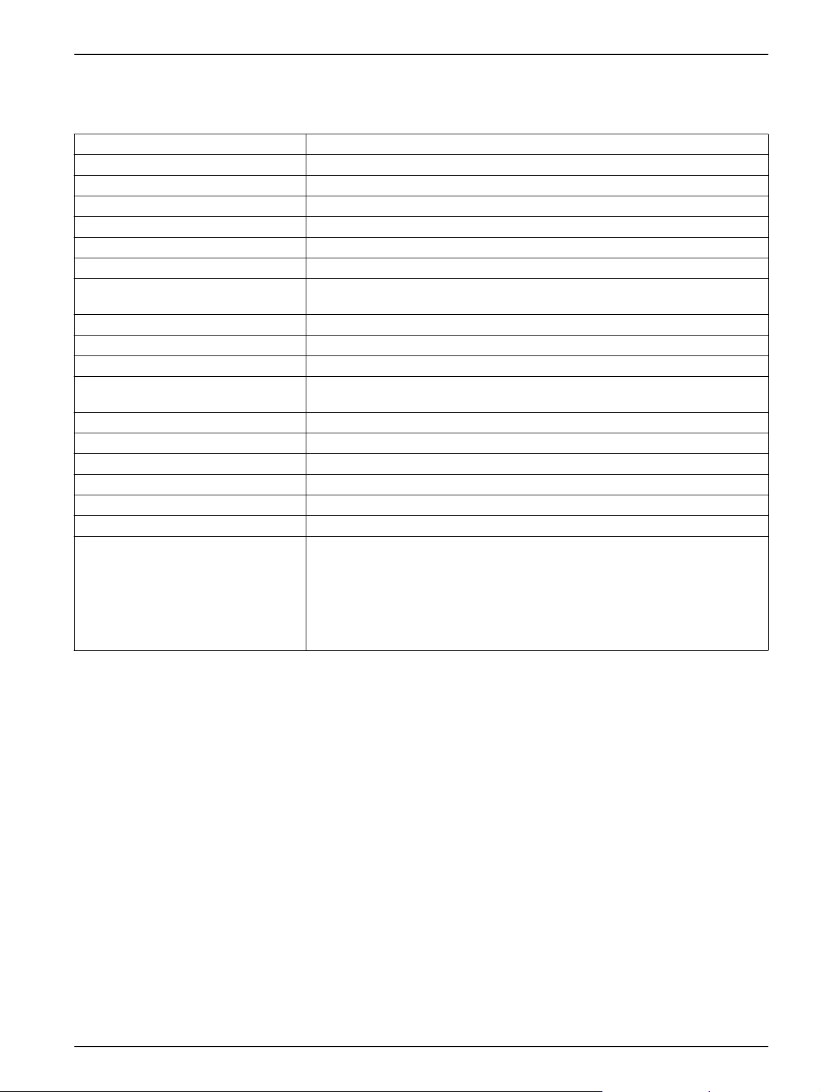
Table 1 Filtration probe sc specifications (in some cases optional extras)
Components Filter module with pump
Dimensions (W × H × D) 330 × 384 × 243 mm (13 × 15.12 × 9.57 inches)
Supply tubing 5 m or 10 m, depending on version
Enclosure Plastic enclosure, PPE, flammability class in accordance with UL 94
Mass Approx. 9.5 kg filter enclosure, approx. 8 kg tubing
Power supply Via analysis instrument
Electrical connection Via analysis instrument
Mean power consumption
Electrical fuse protection Via analysis instrument, via controller
Operating temperature 4 °C...40 °C (39 °F...104 °F), in water
Operating temperature sample tubing –20 °C...45 °C (–4 °F...113 °F); 95 % relative humidity, non-condensing
Storage temperature
Sample temperature 4 °C...40 °C (39 °F...104 °F), water temperature
Permissible sample flow speed max. 3 m/s, from 1 m/s: install only with protection against flow (accessory)
Permissible pH value of the sample 5–9
Maximum immersion depth 3 m (120 inch)
Fastening to the extension pipe 6 screws M5 × 10 mm
Filtrate flow rate
Cables and tubing on the probe pipe
400 VA (brief peak power consumption: 1000 VA),
(with 10 m heated filtration probe tubing)
–20 °C...60 °C (–4 °F...140 °F); 95 % relative humidity, non-condensing
Once the filter modules have become wet, they must be stored wet.
5 ml/minute, 4 out of 5 minutes
Outer sheath of the cables and tubing: UV and weather resistant
Total external diameter of the outer tubing: 32 mm (1.2 inch)
External diameter of the sample tubing 3.2 mm (0.12 inch)
External diameter of the return tubing: 6 mm (0.23 inch)
External diameter of the air tubing: 6 mm (0.23 inch)
External diameter of the data cable: 7.1 mm (0.28 inch)
External diameter of the power cable: 6.1 mm (0.23 inch)
3
Page 6

Specifications
4
Page 7
Section 2 General information
2.1 Safety instructions
Prior to unpacking, commissioning or operating the
instrument, read this manual in its entirety.
Please pay particular attention to all instructions on hazards
and safety. Otherwise there is a risk of serious injury to the
operator or damage to the instrument, or pollution.
The instrument is only allowed to be installed and used as per
the instructions in this manual.
2.1.1 Instructions on hazards in this manual
DANGER
Indicates a potentially hazardous situation or hazardous
situation that, if not avoided, could result in serious injuries or
fatality.
CAUTION
Indicates a possibly hazardous situation that could result in
light to moderate injuries.
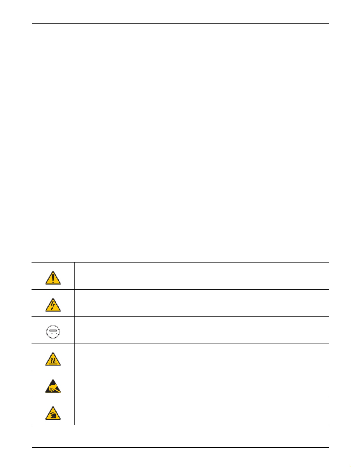
2.1.2 Safety symbols used
This symbol, if present on the instrument, refers to information in the operating instructions on safe
operation and / or instructions that provide safety information.
This symbol, if present on a enclosure or a protective cover for the instrument, identifies the risk of an
electric shock (which may under certain circumstances be fatal). Only personnel qualified for working on
hazardous voltages are allowed to open the enclosure or remove the protective cover.
This symbol, if present on the instrument, identifies the location of a fuse or current limit.
This symbol, if present on the instrument, identifies a part that may become hot and must not be touched
without taking precautions.
Important note: Information that is to be specifically highlighted.
Note: Information with additional aspects on the main text.
Observe all stickers and markings on the instrument. Otherwise
injuries, pollution or damage to the instrument may occur.
This symbol, if present on the instrument, indicates the presence of components that could be damaged by
electrostatic discharge. Appropriate precautions are to be taken.
This symbol, if present on the instrument, indicates the presence of dangerous chemical substances.
Chemicals are only allowed to be handled and maintenance on devices for supplying chemicals to the
instrument is only allowed to be performed by personnel qualified and trained for working with chemicals.
5
Page 8
General information
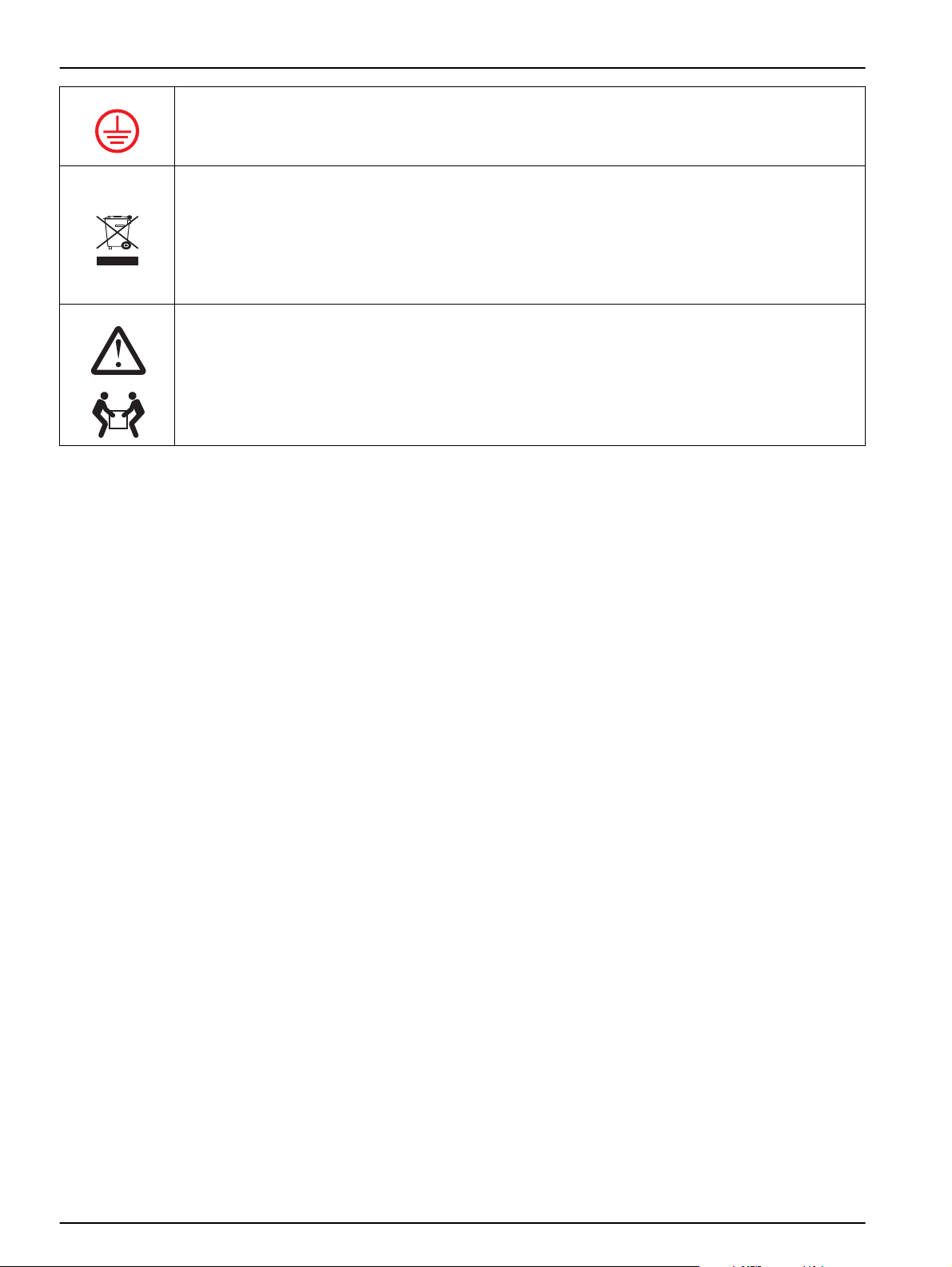
This symbol, if present on the instrument, identifies the location of the connection for the protective earth
(ground).
As of 12 August 2005, electrical appliances marked with this symbol are no longer allowed to be
disposed of in Europe in unsorted household or industrial waste. As per the applicable
regulations, from this date on consumers in the EU must return old appliances to the
manufacturer for disposal. This disposal is free of charge for the consumer.
Note: You can obtain instructions on the correct disposal of all (marked and unmarked) electrical products
that have been supplied or manufactured by Hach-Lange from your local Hach-Lange sales office.
When carrying or transporting the instrument/instrument components and if the total weight is
18-32 kg (39.7-70.5 lbs)
more than 18 kg, make sure that suitable lifting equipment is used and/or that the
instrument/instrument components are carried by 2 people.
2.1.3 General safety instructions
DANGER
Risk of electric shock!
Work on the electrical installation is only allowed to be
performed by an experienced electrician!
Always isolate the instrument from the mains during
installation work!
CAUTION
Observe applicable health and safety regulations!
Flows of sample of unknown composition can produce
hazards due to traces of chemicals, radiation or biological
effects.
Avoid unnecessary contact with the flows of sample of
unknown composition and take appropriate safety measures.
DANGER
Potential danger in the event of contact with
chemical/biological materials. Handling chemical samples,
standards and reagents can be dangerous. Familiarize
yourself with the necessary safety procedure s an d th e correc t
handling of the chemicals before the work and rea d and follow
all relevant safety data sheets.
Normal operation of this instrument may involve the use of
hazardous chemicals or biologically harmful samples.
• Observe all cautionary information printed on the original
solution containers and safety data sheet prior to their use.
• Dispose of all consumed solutions in accordance with national
regulations and laws.
• Select the type of protective equipment suitable to the
concentration and quantity of the dangerous material at the
respective work place.
6
Page 9
2.2 General
2.3 Product description
2.3.1 Identification
General information
In this section you will find information on:
• Instrument identification
• Items supplied
• Operating instructions
• Tasks and obligations of the operating organisation
• The manufacturer
• The declaration of conformity
The filtration probe sc is controller-operated filtration system that is
immersed. It supplies an AMTAX sc or PHOSPHAX sc connected in
series with a filtered sample flow. The filtration probe sc features
automatic cleaning and is largely maintenance-free.
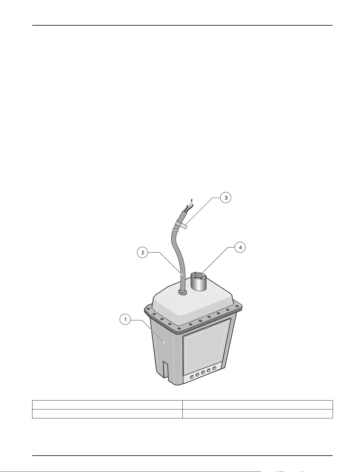
Figure1Filtration probesc
1 Filtration probe sc 3 Rating plate
2 Supply cable 4 Connection fastening system
7
Page 10

General information
2.3.1.1 Rating plate for the filtration probe sc
You will find the rating plate at the top end of the supply cable. On
the rating plate you will find
• The model number and the serial number,
• Information on the voltage and frequency for the electrical
connection and
• Information on the brief peak power consumption.
2.3.2 Principle of operation
The filtration probe sc draws in liquid through a filter system and
then pumps this sample flow to an analysis instrument connected in
series. After the analysis of the sample, the analysis instrument
pumps the sample (possibly mixed with chemicals) back to the tank
sampled or to a drain.
A cleaning device ensures the filter modules remain porous. The
filtration probe sc has a compressed air tube that terminates
underneath the filter modules. When compressed air flows out of
the air openings underneath the filter modules, the rising air
bubbles remove soiling from the filter modules. In this way the filter
modules remain porous and manual cleaning is largely
unnecessary.
2.4 Items supplied
Standard items supplied:
• Filtration probe sc
• These operating instructions
• 2 filter modules
• Small parts, cable, tubing and connector set and
• One cleaning sponge
2.4.1 Identification of the operating instructions
You will find a DOC number on the cover sheet so that you can
re-order these operating instructions. You can identify the issue of
the operating instructions using the date in the DOC number.
8
Page 11

2.5 Target group for these operating instructions
These operating instructions are directed at sewage treatment plant
operating organisations and trained and experienced staff sewage
treatment plant supervisors. It is assumed that these persons are
familiar with the operation of personal computers and have a sound
knowledge of
• Measurement and control systems,
• Electrical engineering,
• Water analysis and
• Chemistry
and have been adequately instructed on safety regulations.
Requirements and activities that go beyond the knowledge and
skills held by a sewage treatment plant supervisor must be
entrusted by this person to trained (e. g. electrical) specialists. Such
work is to be planned and co-ordinated in agreement with the
organisation or plant management.
2.6 Tasks and obligations of the operating organisation
General information
The organisation operating the plant must ensure only qualified and
trained personnel install, operate or otherwise use this probe. The
operating organisation must ensure the locally applicable
regulations are observed and that these operating instructions are
always available to the plant operators.
2.6.1 Correct use
Incorrect use of the filtration probe sc or its components
and / or its accessories can cause injury, damage or pollution.
Ensure the filtration probe sc and / or its components and / or
its accessories are only used correctly.
The filtration probe sc was developed for the filtration, supply and
disposal of liquid samples and for connection to an analysis
instrument. The primary area of application is water and waste
water analysis.
2.6.1.1 Incorrect use
Any other use or use beyond that defined above is considered
incorrect use and will also render void all claims under the
guarantee and warranty.
2.7 Your service partner, contacting the manufacturer
In section Contact on page 39 you will find addresses and
telephone numbers for the various contacts.
9
Page 12

General information
2.7.1 Standards and declaration of conformity
The filtration probe sc and its components comply with the
applicable standards and stipulations.
For the filtration probe sc we confirm compliance.
HACH LANGE GmbH is certified to DIN EN ISO9001.
You can obtain further information on certificates, the declaration of
conformity and standards on request.
2.7.2 Copyright
"Provision to third parties as well as the duplication of these
operating instructions, further processing and provision of their
content to third parties is not allowed unless expressly approved.
Contravention will result in the obligation to pay damages.
All rights reserved in the case of the award of a patent or
registration of a design." (In accordance with DIN 34, ISO 16016)
10
Page 13

Section 3 Installation
3.1 Safety instructions
In this section you will find information on the following for the
filtration probe sc
• Installing,
• Connecting,
• Connecting to the mains and
• Connecting to the data network.
DANGER
Prior to unpacking, commissioning or operating the
instrument, read all of this manual!
Pay particular attention to all instructions on hazards and
safety. Otherwise there is a risk of serious injury to the
operator or damage to the instrument, or pollution!
The analysis instrument and its peripherals a re only allowed to
be installed and connected by qualified personnel. Only use
appropriate (e. g. insulated) tools and observe the applicable
rules and regulations!
Incorrect connection to the data network or incorrect
configuration can result in damage to the modules and the
customer's network!
3.1.1 Safety measures prior to unpacking, connecting and operating
Ensure only trained and instructed personnel unpack, install,
connect or operate the filtration probe sc.
3.1.2 Disposing of the packaging
Protect the environment when disposing of the packaging and
observe locally applicable regulations
11
Page 14

Installation
3.1.3 Preparing the installation
DANGER
Risk of electric shock!
Plan the mechanical fastening before you position posts or
drill holes. Choose a suitable place to install the instrument.
Plan how the cables and tubing will be laid and their routes.
Note that the cables will need to be removed regularly.
Lay cables and tubing so they will not cause tripping and
without sharp bends. Note that the cables will need to be
removed regularly.
Do not connect the electrical power supply to the mains until
the instrument has been fully wired and fused.
Provide adequate fuse protection for the electrical power
supply.
Always connect a residual current circuit breaker (trigger
current max.: 30 mA) between the mains and the system!
If you install the instrument outside, provide overvoltage
protection between the mains and the system!
12
Page 15

3.2 Drawing with dimensions
Installation
Figure 2 Drawing with dimensions
13
Page 16

Installation
3.3 Installing the filtration probe sc
Important note: Improper assembly or installation of the filtration
probe sc or its components can result in injury or damage.
The filtration probe sc and its components are only allowed to be
installed by qualified and trained personnel.
Install the filtration probe sc prior to commissioning the analysis
instrument.
3.3.1 Sealing exhaust
If you do not dispose of the used sample via the filtration probe sc,
seal the exhaust.
1. Seal the exhaust using the sealing cap supplied.
14
Figure 3 Sealing exhaust
Page 17

3.3.2 Installing filter module
Installation
Important note: Do not let the filter modules dry out, as dry filter
modules will become unusable immediately and cannot be
repaired.
Never touch the filter surface, as the filter surface will be destroyed
by the grease from the skin.
Never immerse the filtration probe in water without filter modules,
as unfiltered water could block the filtration probe.
1. Insert the filter module in the bottom.
2. Pivot the filter module towards the inside and press onto the
frame until it engages.
Figure 4 Installation of the filter modules
3. Proceed with the second filter module on the other side in the
same way.
15
Page 18

Installation
3.3.3 Installing filtration probe sc
Important note: Only install the filtration probe sc using the rim
mounting system.
Figure 5 Installation parts rim mounting LZX414.00.50000
1 Mounting pipe 7 Cheese head screws M5 × 20 mm (6×)
2 Screws M5 × 16 mm (6×) 8 Flat bar
3 Quick-fit anchors (4) 9 Cheese head screws M8 × 40 mm (4×)
4 Base 10 Plug
5 Clamp half 11 Spring cotter
6 Clamp half with thread
16
Page 19

Installation
Figure 6 Installation of the rim mounting LZX414.00.5000
1 Base 6 Flat bar
2 Quick-fit anchors (4) 7 Screws
3 Plug 8 Screws M5 × 16 mm (6×)
4 Spring cotter 9 Filtration probe tubing
5 Mounting pipe 10 Filtration probe sc
Important note: Only install the filtration probe sc in flowing water
with protection against flow.
Install the filtration probe sc so that is it held min. 0.1 m and max.
3 m below the surface of the water.
In case of frost, insulate the first 10 cm of the tubing if the top edge
of the filtration probe sc is not at least 20 cm below the surface of
the water.
17
Page 20

Installation
Important note: Ensure the filtration probe sc is not in contact with
the base of the tank and cannot bang against the side walls.
Figure 7 Installation position for the filtration probe sc
18
Page 21

Installation
3.4 Supply of power
Figure 8 Installing with rim mounting
DANGER
Risk of electric shock!
Work on the electrical system is only allowed to be performed
by trained and experienced electricians.
19
Page 22

Installation
3.4.1 Connecting power cable
1. Open the analysis instrument to which the filtration probe sc is
to be connected.
2. Connect the earth wire (Figure 9-3) (see also the operating
instructions for the analysis instrument).
3. Connect the power cable to the filtration probe sc (Figure 9-2).
(see also the operating instructions for the analysis instrument)
4. Connect the power cable for the drain heating (optional
accessory) (Figure 9-1). (see also the operating instructions for
the analysis instrument)
Figure 9 Connecting power supply and heating to the filtration probe sc
1 Connection drain heating
(optional)
20
2 Filtration probe sc power
cable connection
3 Earth wire terminal strip 4 Filtration probe sc data
cable connection
Page 23

3.5 Connecting filtration probe sc to the data network
To ensure correct operation, the filtration probe sc must be
connected to the analysis instrument's data network. The analysis
instrument's data network sends the commands for self-cleaning
and transmits the module pressure value to the analysis instrument.
1. Connect the data cable connector to the socket on the analysis
instrument (Figure 9-4)
(see also the operating instructions for the analysis instrument).
3.6 Connecting sample tubing
Note: Pay attention to the markings on the tubing.
1. Connect the black sample return tubing (Figure 10-1) to the
sample outlet on the analysis instrument (see operating
instructions for the analysis instrument).
2. Connect the transparent sample feed tubing (Figure 10-2) to
the sample inlet on the analysis instrument (see operating
instructions for the analysis instrument).
Installation
Figure 10 Connecting sample tubing
1 Sample return 2 Sample feed
21
Page 24

Installation
3.7 Connecting air tubing
Note: Pay attention to the markings on the tubing.
1. Connect the white air tubing to the analysis instrument (see
operating instructions for the analysis instrument).
Figure 11 Connecting air tubing
22
Page 25

Section 4 System startup
Important note: Correct installation of the system is necessary to
ensure malfunction-free operation. Prior to initial commissioning,
ensure the system has been correctly installed and only author ised
persons have access to the system.
On initial commissioning, ensure all internal and external
expansions are correctly registered in the controller system.
4.1 Initial commissioning
1. Ensure the filtration probe sc is completely and correctly
installed.
2. Switch on the analysis instrument and check whether the
filtration probe sc is correctly registered in the system.
3. Follow the instructions in the operating instructions for the
analysis instrument.
The filtration probe sc is then ready for use.
23
Page 26

System startup
24
Page 27

Section 5 Operation
5.1 The operation concept
No actions are intended to be performed by the operator on the
filtration probe sc (except cleaning and replacement of the filter
modules). All commands and control instructions are sent
automatically by the analysis instrument connected or are made via
the controller. Read the operating instructions for the analysis
instrument and the controller thoroughly to ensure you can operate
the system safely, without errors and correctly.
5.1.1 Rectifying problems in normal operation
In normal operation only feasible, sensible entry options are
displayed. If you then enter incorrect values, these will be rejected.
If you have made incorrect entries, repeat the entry with the correct
values.
Note: If your entry was outside a logical working range, a correction is
made automatically. Note that the value is then still incorrect and must be
corrected.
5.2 Normal operation
In normal operation the filtration probe sc does not require
supervision, operation or maintenance.
5.2.1 Rectifying problems in operation
5.2.1.1 Problems with the sensors or the analysis instruments
If a sensor or analysis instrument is reporting errors or warnings, a
corresponding error will be displayed on the controller (see
operating instructions for the controller).
5.2.1.2 Module pressure value too low
If the filter modules block, the module pressure value in the filtration
probe sc drops.
Pressure value State Action
< 0.25 bar Blocked Replace filter modules
0.25 bar...0.45 bar Soiled Clean filter modules
> 0.45 bar ok No action
1. Clean or replace the filter modules (see Cleaning / replacing
filter modules" on page 28).
2. Check all relevant settings.
If the problems have not been rectified, please contact customer
service.
25
Page 28

Operation
26
Page 29

Section 6 Maintenance and cleaning
CAUTION
When carrying or transporting the instrument/instrument
components and if the total weight is more than 18 kg, make
sure that suitable lifting equipment is used and/or that the
instrument/instrument components are carried by 2 people.
6.1 Maintenance and cleaning by the operator
• Regularly check the filtration probe sc for mechanical damage.
• Regularly check the filter modules for mechanical damage.
• Regularly check all connections for leaks and corrosion.
• Regularly check all cables and tubing for mechanical damage.
• Clean the filter modules using the damp sponge from the
accessories.
• Clean the filtration probe sc (not the filter modules) with a
cloth. You can use a brush for stubborn soiling.
6.1.1 Troubleshooting, error state diagnostics and repair
6.1.1.1 Module pressure value too low
Pressure value State Action
< 0.25 bar Blocked Replace filter modules
0.25 bar...0.45 bar Soiled Clean filter modules
> 0.45 bar ok No action
If the filter modules block, the module pressure value in the filtration
probe sc drops.
Clean the filter modules or replace the filter modules
(see Cleaning / replacing filter modules on page 28).
27
Page 30

Maintenance and cleaning
6.1.2 Cleaning / replacing filter modules
Note:
The filter modules are very delicate.
Only clean the filter modules very carefully using the damp sponge
supplied.
Clean the filter modules
• Regularly (min. every 3 months) or
• When the pressure values drop below 0.45 bar.
DANGER
Potential danger in the event of contact with
chemical/biological materials. Handling chemical samples,
standards and reagents can be dangerous. Familiarize
yourself with the necessary safety procedure s an d th e correc t
handling of the chemicals before the work and rea d and follow
all relevant safety data sheets.
Normal operation of this instrument may involve the use of
hazardous chemicals or biologically harmful samples.
• Observe all cautionary information printed on the original
solution containers and safety data sheet prior to their use.
• Dispose of all consumed solutions in accordance with national
regulations and laws.
• Select the type of protective equipment suitable to the
concentration and quantity of the dangerous material at the
respective work place.
NEVER use chlorine bleach together with hydrochloric acid
(Risk of the formation of chlorine gas).
For cleaning use chlorine bleach (5 %–10 %) OR hydrochloric
acid (5 %).
Avoid the contact of cleaning agents and soaps with filter
modules as these may render the filter modules unusable.
1. On the SENSOR SETUP menu on the analysis instrument,
choose the TEST/MAINT, SERVICE MODE command and
accept.
2. Take the filtration probe sc out of the tank.
3. Clean the filter modules carefully using the damp sponge
supplied.
28
4. Carefully lever the filter modules out of the holder using a
screwdriver.
5. Clean or replace the filter modules.
6. Fit the new or cleaned filter modules in the bottom.
Page 31

Maintenance and cleaning
7. Press up the filter modules against the enclosure until they
engage.
Figure 12 Changing filter module
8. Hang the filtration probe sc back in the tank.
9. On the SENSOR SETUP menu on the analysis instrument,
choose the TEST/MAINT and PREPUMPING PROBE
commands and accept.
10. Wait until the pumping operation is complete.
11. Leave the service state using the "Back" arrow.
12. Answer the SERV. HOLD MODE? prompt with NO/MEASURE
START.
13. On the SENSOR SETUP menu choose the MEASURING and
ON commands and accept.
Table 2 List of consumables and warranty periods
Designation Replace after Spare part No.
Filter module for filtration probe 1 year LZY140
29
Page 32

Maintenance and cleaning
6.2 Maintenance and cleaning by qualified personnel
The filtration probe sc is only allowed to be opened by qualified and
authorised service personnel.
The following consumables in the filtration probe sc should be
changed at regular intervals by the service personnel:
Table 3 List of consumables and warranty periods
Designation Replace after Warranty Spare part No.
Set of wear parts for sample pump
(Pump membrane + valves)
Exhaust (copper) 1 year 1 year LZY139
Exhaust (2 pcs.) for air cleaning
(Air exhaust set, incl. sealing and screws)
6.2.1 Changing exhaust
1 year, with 5 min. analysis interval
Otherwise 2 years
1 year 1 year LZY138
1 year LZY130
If you dispose of the used sample via the filtration probe sc, renew
the exhaust after 1 year.
1. Unscrew the exhaust from the enclosure.
30
Figure 13 Changing exhaust
2. Screw the new exhaust into the enclosure and tighten it
hand-tight.
Page 33

6.2.2 Changing air exhaust
Maintenance and cleaning
1. Undo the 12 screws for the outlet.
2. Replace the exhaust and the sealing.
3. Tighten the 12 screws hand-tight.
4. Change the exhaust on the other side of the filtration probe sc.
Figure 14 Changing air exhaust
31
Page 34

Maintenance and cleaning
32
Page 35

Section 7 Taking out of operation
7.1 Taking out of operation for a short period
No special measures are necessary for taking out of operation for a
short period (up to a week in frost-free ambient conditions).
Important note: If the supply of power to the controller is
interrupted, frost damage may occur.
Ensure the instrument and tubing cannot freeze.
1. Interrupt the measurement and switch the analysis instrument
to the service state.
7.2 Taking out of operation for an extended period
If the filter modules may dry out (e.g. on cleaning the tank), in case
of risk of frost or if the filtration probe sc is to be taken out of
operation for an extended period, please work through the following
list:
1. Take the analysis instrument out of operation in accordance
with the operating instructions for the analysis instrument.
2. Isolate the filtration probe sc from the mains.
3. Take the filtration probe sc out of the tank.
Important note: Do not let the filter modules dry out, as dry filter
modules will become unusable immediately and cannot be
repaired.
4. Dismantle the filter modules.
5. Store the filter modules in clean water.
6. Wrap the filtration probe sc in protective film or a dry cloth.
7. Store the filtration probe sc dry.
7.3 Finally taking out of operation
When you want to finally take the filtration probe sc out of
operation, proceed as described for intermediate storage.
7.4 Intermediate storage or storage
Proceed as for taking out of operation for an extended period.
33
Page 36

Taking out of operation
34
Page 37

Section 8 Replacement Parts, consumables,
accessories
8.1 Replacement parts and their order numbers
Item Description 1 Description 2 Order No.
Set of seals for filtration probe incl. O-ring, connector press. sensor LZY121
-- Set of wear parts for sample pump incl. membrane, valves, screws LZY130
-- Tubing for filtration probe FEP tubing 1 × 3.1 mm, 1.00 m LZY131
-- Air tubing for filtration probe 4/6 mm, PUR-H LZY132
1 Sample tubing 230 V, 5 m incl. top cover and adaptor LZY112
1 Sample tubing 115 V, 5 m incl. top cover and adaptor LZY113
1 Sample tubing 230 V, 10 m incl. top cover and adaptor LZY114
1 Sample tubing 115 V, 10 m incl. top cover and adaptor LZY115
2 Top cover filtration probe (plastic part) LZY116
3 Enclose filtration probe (plastic part) without top cover LZY117
5 Sealing top cover for filtration probe LZY119
6 Set of screws for filtration probe (28 pieces) LZY120
9 Adaptor suction side LZY128
-- Set of screws (4 of each type used) LZY314
10 Adaptor physical page LZY129
12 Card filtration probe with press. sensor ZBA804 YAB042
13 Set of fittings 3.2 mm (4 pieces) LZY111
14 T-fitting 4/6 mm LZY133
15 Fitting for tubing DN 4/6 LZY134
16 Elbow fitting 4/6 mm LZY135
17 Fitting for exhaust valve incl. O-ring LZY136
18 Humidity sensor incl. connector LZY137
20 Exhaust (copper) LZY139
21 Adaptor for filtration probe with flange + screws LZY118
22 Safety cover filtration probe incl. pads and screws LZY122
23 Exhaust valve 230 V incl. cable, connector, fittings, screws LZY123
23 Exhaust valve 115 V incl. cable, connector, fittings, screws LZY124
24 Sample pump 230 V incl. sleeve cable and connector LZY125
24 Sample pump 115 V incl. sleeve cable and connector LZY126
25 Sleeve nut with sealing LZY127
26 Exhaust (2 pcs.) for air cleaning incl. sealing/screws LZY138
27 Coupling piece incl. screws LZY265
28 Locking screw probe adaptor LZY213
29 Seal for filter module O-ring 7,50 × 2,50 (4 pieces) LZY142
30 Filter module for filtration probe LZY140
31 Adaptor for filtration module including sealing LZY141
32 Connection tubing for filtr. probe 4/6 mm, PTFE 25 cm LZY253
35
Page 38

Replacement Parts, consumables, accessories
8.2 Accessories
Description 1 Description 2 Order No.
Sponge EZZ062
Set of small parts 2 spring cotter with chains + 6 screws LZY245
8.3 Optional accessories
Description Description 2 Order No.
Rim mounting for filtration probe sc LZX414.00.50000
Rail mounting for filtration probe sc LZX414.00.60000
Protection against flow LZY317
36
Page 39

Replacement Parts, consumables, accessories
37
Page 40

Replacement Parts, consumables, accessories
38
Page 41

Section 9 Contact
HACH Company
World Headquarters
P.O. Box 389
Loveland, Colorado
80539-0389 U.S.A.
Tel (800) 227-HACH
(800) -227-4224
(U.S.A. only)
Fax (970) 669-2932
orders@hach.com
www.hach.com
HACH LANGE GMBH
Willstätterstraße 11
D-40549 Düsseldorf
Tel. +49 (0)2 11 52 88-320
Fax +49 (0)2 11 52 88-210
info@hach-lange.de
www.hach-lange.de
HACH LANGE GMBH
Rorschacherstrasse 30a
CH-9424 Rheineck
Tel. +41 (0)848 55 66 99
Fax +41 (0)71 886 91 66
info@hach-lange.ch
www.hach-lange.ch
Repair Service in the
United States:
HACH Company
Ames Service
100 Dayton Avenue
Ames, Iowa 50010
Tel (800) 227-4224
(U.S.A. only)
Fax (515) 232-3835
HACH LANGE LTD
Pacific Way
Salford
GB-Manchester, M50 1DL
Tel. +44 (0)161 872 14 87
Fax +44 (0)161 848 73 24
info@hach-lange.co.uk
www.hach-lange.co.uk
HACH LANGE FRANCE
S.A.S.
8, mail Barthélémy Thimonnier
Lognes
F-77437 Marne-La-Vallée
cedex 2
Tél. +33 (0) 820 20 14 14
Fax +33 (0)1 69 67 34 99
info@hach-lange.fr
www.hach-lange.fr
Repair Service in Canada:
Hach Sales & Service
Canada Ltd.
1313 Border Street, Unit 34
Winnipeg, Manitoba
R3H 0X4
Tel (800) 665-7635
(Canada only)
Tel (204) 632-5598
Fax (204) 694-5134
canada@hach.com
HACH LANGE LTD
Unit 1, Chestnut Road
Western Industrial Estate
IRL-Dublin 12
Tel. +353(0)1 460 2522
Fax +353(0)1 450 9337
info@hach-lange.ie
www.hach-lange.ie
HACH LANGE NV/SA
Motstraat 54
B-2800 Mechelen
Tel. +32 (0)15 42 35 00
Fax +32 (0)15 41 61 20
info@hach-lange.be
www.hach-lange.be
Repair Service in
Latin America, the
Caribbean, the Far East,
Indian Subcontinent, Africa,
Europe, or the Middle East:
Hach Company World
Headquarters,
P.O. Box 389
Loveland, Colorado,
80539-0389 U.S.A.
Tel +001 (970) 669-3050
Fax +001 (970) 669-2932
intl@hach.com
HACH LANGE GMBH
Hütteldorfer Str. 299/Top 6
A-1140 Wien
Tel. +43 (0)1 912 16 92
Fax +43 (0)1 912 16 92-99
info@hach-lange.at
www.hach-lange.at
DR. LANGE NEDERLAND
B.V.
Laan van Westroijen 2a
NL-4003 AZ Tiel
Tel. +31(0)344 63 11 30
Fax +31(0)344 63 11 50
info@hach-lange.nl
www.hach-lange.nl
HACH LANGE APS
Åkandevej 21
DK-2700 Brønshøj
Tel. +45 36 77 29 11
Fax +45 36 77 49 11
info@hach-lange.dk
www.hach-lange.dk
HACH LANGE LDA
Av. do Forte nº8
Fracção M
P-2790-072 Carnaxide
Tel. +351 214 253 420
Fax +351 214 253 429
info@hach-lange.pt
www.hach-lange.pt
HACH LANGE KFT.
Vöröskereszt utca. 8-10.
H-1222 Budapest XXII. ker.
Tel. +36 1 225 7783
Fax +36 1 225 7784
info@hach-lange.hu
www.hach-lange.hu
HACH LANGE AB
Vinthundsvägen 159A
SE-128 62 Sköndal
Tel. +46 (0)8 7 98 05 00
Fax +46 (0)8 7 98 05 30
info@hach-lange.se
www.hach-lange.se
HACH LANGE SP. ZO.O.
ul. Krakowska 119
PL-50-428 Wrocław
Tel. +48 801 022 442
Zamówienia: +48 717 177 707
Doradztwo: +48 717 177 777
Fax +48 717 177 778
info@hach-lange.pl
www.hach-lange.pl
HACH LANGE S.R.L.
Str. Căminului nr. 3,
et. 1, ap. 1, Sector 2
RO-021741 Bucureşti
Tel. +40 (0) 21 205 30 03
Fax +40 (0) 21 205 30 17
info@hach-lange.ro
www.hach-lange.ro
HACH LANGE S.R.L.
Via Rossini, 1/A
I-20020 Lainate (MI)
Tel. +39 02 93 575 400
Fax +39 02 93 575 401
info@hach-lange.it
www.hach-lange.it
HACH LANGE S.R.O.
Zastrčená 1278/8
CZ-141 00 Praha 4 - Chodov
Tel. +420 272 12 45 45
Fax +420 272 12 45 46
info@hach-lange.cz
www.hach-lange.cz
HACH LANGE
8, Kr. Sarafov str.
BG-1164 Sofia
Tel. +359 (0)2 963 44 54
Fax +359 (0)2 866 15 26
info@hach-lange.bg
www.hach-lange.bg
HACH LANGE S.L.U.
Edificio Seminario
C/Larrauri, 1C- 2ª Pl.
E-48160 Derio/Vizcaya
Tel. +34 94 657 33 88
Fax +34 94 657 33 97
info@hach-lange.es
www.hach-lange.es
HACH LANGE S.R.O.
Roľnícka 21
SK-831 07 Bratislava –
Vaj nory
Tel. +421 (0)2 4820 9091
Fax +421 (0)2 4820 9093
info@hach-lange.sk
www.hach-lange.sk
HACH LANGE SU
ANALİZ SİSTEMLERİ
LTD.ŞTİ.
Ilkbahar mah. Galip Erdem
Cad. 616 Sok. No:9
TR-Oran-Çankaya/ANKARA
Tel. +90312 490 83 00
Fax +90312 491 99 03
bilgi@hach-lange.com.tr
www.hach-lange.com.tr
39
Page 42

Contact
HACH LANGE D.O.O.
Fajfarjeva 15
SI-1230 Domžale
Tel. +386 (0)59 051 000
Fax +386 (0)59 051 010
info@hach-lange.si
www.hach-lange.si
HACH LANGE OOO
Finlyandsky prospekt, 4A
Business Zentrum “Petrovsky
fort”, R.803
RU-194044, Sankt-Petersburg
Tel. +7 (812) 458 56 00
Fax. +7 (812) 458 56 00
info.russia@hach-lange.com
www.hach-lange.com
ΗΑCH LANGE E.Π.Ε.
Αυλίδος 27
GR-115 27 Αθήνα
Τηλ . +30 210 7777038
Fax +30 210 7777976
info@hach-lange.gr
www.hach-lange.gr
HACH LANGE D.O.O.
Ivana Severa bb
HR-42 000 Varaždin
Tel. +385 (0) 42 305 086
Fax +385 (0) 42 305 087
info@hach-lange.hr
www.hach-lange.hr
HACH LANGE MAROC
SARLAU
Villa 14 – Rue 2 Casa
Plaisance
Quartier Racine Extension
MA-Casablanca 20000
Tél. +212 (0)522 97 95 75
Fax +212 (0)522 36 89 34
info-maroc@hach-lange.com
www.hach-lange.ma
40
Page 43

Section 10 Warranty, liability and complaints
HACH LANGE GmbH warrants that the product supplied is free of
material and manufacturing defects and undertakes the obligation
to repair or replace any defective parts at zero cost.
The warranty period for instruments is 24 months. If a service
contract is taken out within 6 months of purchase, the warranty
period is extended to 60 months.
With the exclusion of the further claims, the supplier is liable for
defects including the lack of assured properties as follows: all those
parts that, within the warranty period calculated from the day of the
transfer of risk, can be demonstrated to have become unusable or
that can only be used with significant limitations due to a situation
present prior to the transfer of risk, in particular due to incorrect
design, poor materials or inadequate finish will be improved or
replaced, at the supplier's discretion. The identification of such
defects must be notified to the supplier in writing without delay,
however at the latest 7 days after the identification of the fault. If the
customer fails to notify the supplier, the product is considered
approved despite the defect. Further liability for any direct or
indirect damages is not accepted.
If instrument-specific maintenance and servicing work defined by
the supplier is to be performed within the warranty period by the
customer (maintenance) or by the supplier (servicing) and these
requirements are not met, claims for damages due to the failure to
comply with the requirements are rendered void.
Any further claims, in particular claims for consequential damages
cannot be made.
Consumables and damage caused by improper handling, poor
installation or incorrect use are excluded from this clause.
HACH LANGE GmbH process instruments are of proven reliability
in many applications and are therefore often used in automatic
control loops to provide the most economical possible operation of
the related process.
To avoid or limit consequential damage, it is therefore
recommended to design the control loop such that a malfunction in
an instrument results in an automatic change over to the backup
control system; this is the safest operating state for the environment
and the process.
41
Page 44

Warranty, liability and complaints
42
Page 45

Index
A
Accessories .................................................................. 35
C
Changing air exhaust.................................................... 31
Cleaning .................................................................27
Connecting air tubing.................................................... 22
Connecting sample tubing............................................ 21
Consumables..........................................................30
Copyright ...................................................................... 10
, 30
, 35
D
Disposal
Packaging .............................................................. 11
Drawing with dimensions.............................................. 13
E
Exhaust
Changing................................................................ 30
Sealing ................................................................... 14
F
Filter module
Installation.............................................................. 15
Filter modules
Cleaning / replacing ............................................... 28
Filtrate flow rate .............................................................. 3
M
Maintenance........................................................... 27, 30
Module pressure value too low..................................... 25
O
Operating instructions
Identification............................................................. 8
Operating temperature ................................................... 3
Order numbers ............................................................. 35
P
Packaging..................................................................... 11
Personnel, qualified...................................................... 11
Power supply.................................................................. 3
Pressure value ....................................................... 25
Problem rectification..................................................... 25
, 27
R
Replacement parts ....................................................... 35
S
Sample temperature....................................................... 3
T
Taking out of operation................................................. 33
The declaration of conformity ....................................... 10
Troubleshooting............................................................ 27
I
Installation .................................................................... 14
Preparing ............................................................... 12
Intermediate storage..................................................... 33
Items supplied ................................................................ 8
U
Use
Correct ..................................................................... 9
Incorrect................................................................... 9
43
Page 46

44
 Loading...