

Page 1
Instruction Sheet
Cleaning Unit
Safety Information
Please read this entire document before unpacking, setting up, or operating this
equipment. Pay attention to all danger and caution statements. Failure to do so could
result in serious injury to the operator or damage to the equipment.
Make sure that the protection provided by this equipment is not impaired, do not use or
install this equipment in any manner other than that specified in this document.
Use of Hazard Information
DANGER
Indicates a potentially or imminently hazardous situation which, if not avoided, will
result in death or serious injury.
WARNING
Indicates a potentially or imminently hazardous situation which, if not avoided,
could result in death or serious injury.
DOC307.53.00747
Electrical equipment marked with this symbol may not be disposed of in European public disposal systems after
12 August of 2005. In conformity with European local and national regulations (EU Directive 2002/96/EC),
European electrical equipment users must now return old or end-of life equipment to the Producer for disposal at no
charge to the user.
Note: For return for recycling, please contact the equipment producer or supplier for instructions on how to return
end-of-life equipment, producer-supplied electrical accessories, and all auxiliary items for proper disposal.
Introduction
CAUTION
Indicates a potentially hazardous situation that may result in minor or moderate
injury.
Important Note: Indicates a situation which, if not avoided, may cause damage to the
instrument. Information that requires special emphasis.
Note: Information that supplements points in the main text.
Precautionary Labels
Read all labels and tags attached to the instrument. Personal injury or damage to the
instrument could occur if not observed. A symbol, if noted on the instrument, will be
included with a danger or caution statement in the manual.
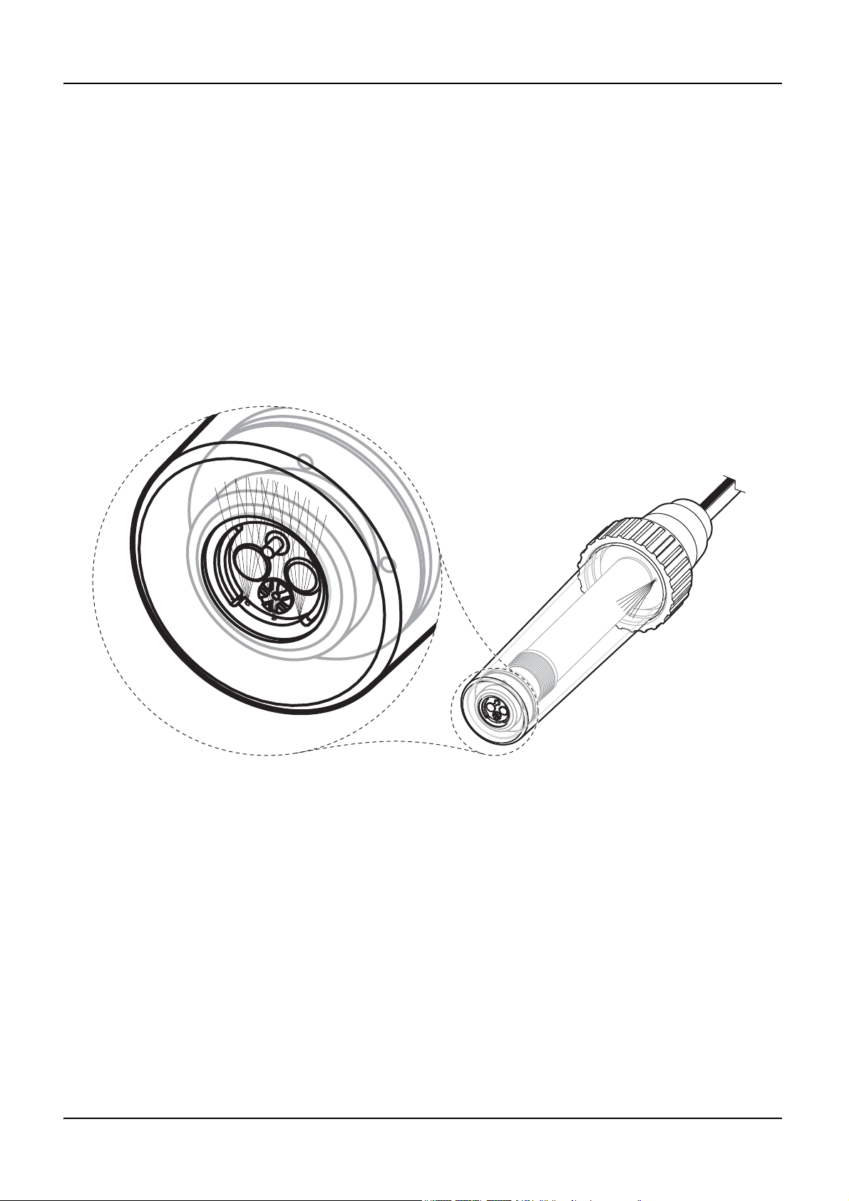
The cleaning unit is designed for automatically cleaning the sensor cartridge membranes
(refer to Figure 1 on page 2). The streamlined design of the cleaning unit minimises the
points where interferences could occur. Refer to Figure 3 on page 3 for the cleaning unit
dimensions.
The cleaning unit is exactly matched to the sensors so that the sensor cartridge
membranes are kept clean even in difficult inlet applications. The cleaning head requires
compressed air (2 to 3.5 bar (29.01 to 50.76 psi) maximum) that is produced by a
compressor or supplied from an existing compressed air system.
Important Note: The compressed air must be oil free.
1
Page 2
Cleaning Unit
The manufacturer recommends using the High Output Airblast Cleaning System for the
compressed air supply; this is a compressor in a weather-proof plastic housing. This
complete system is operated through a relay in the sc100/sc1000 controller.
DANGER
Only qualified personnel should conduct the tasks described in this instruction
sheet.
CAUTION
Make sure the cleaning unit is disconnected from the compressed air during
installation and service work.
When using an external compressor or an existing compressed air system, a suitable
valve is required (and, if necessary, a pressure reducer) and can be configured through a
relay on the sc100/sc1000 controller.
Figure 1 Principle of operation of the cleaning unit
Unpacking the instrument
Verify that all items (refer to Figure 3 on page 3) are included. If any items are missing or
damaged, contact the manufacturer or a sales representative.
Do not send the items without contacting the manufacturer or a sales representative.
Note: Retain the original packaging materials. Instruments returned for service should be shipped in
the original packaging material to protect against damage during transportation.
2
Page 3

Cleaning Unit
Figure 2 Items supplied with the cleaning unit
1 Sleeve 7 Sleeve insert
2 Cleaning insert set (with 2 pre-assembled O-rings) 8 Male fitting (thread 1/8", for ID 6 mm tube)
3 Cleaning insert 9 Cable tie
4 O-ring 10 Adapter, 1.5 inch NPT external thread
5 Sleeve insert set (with 2 pre-assembled O-rings) 11 Union nut
6 O-ring
1
Items supplied are subject to change without notice
1
Dimensions
Figure 3 Dimensions
Installing the cleaning unit
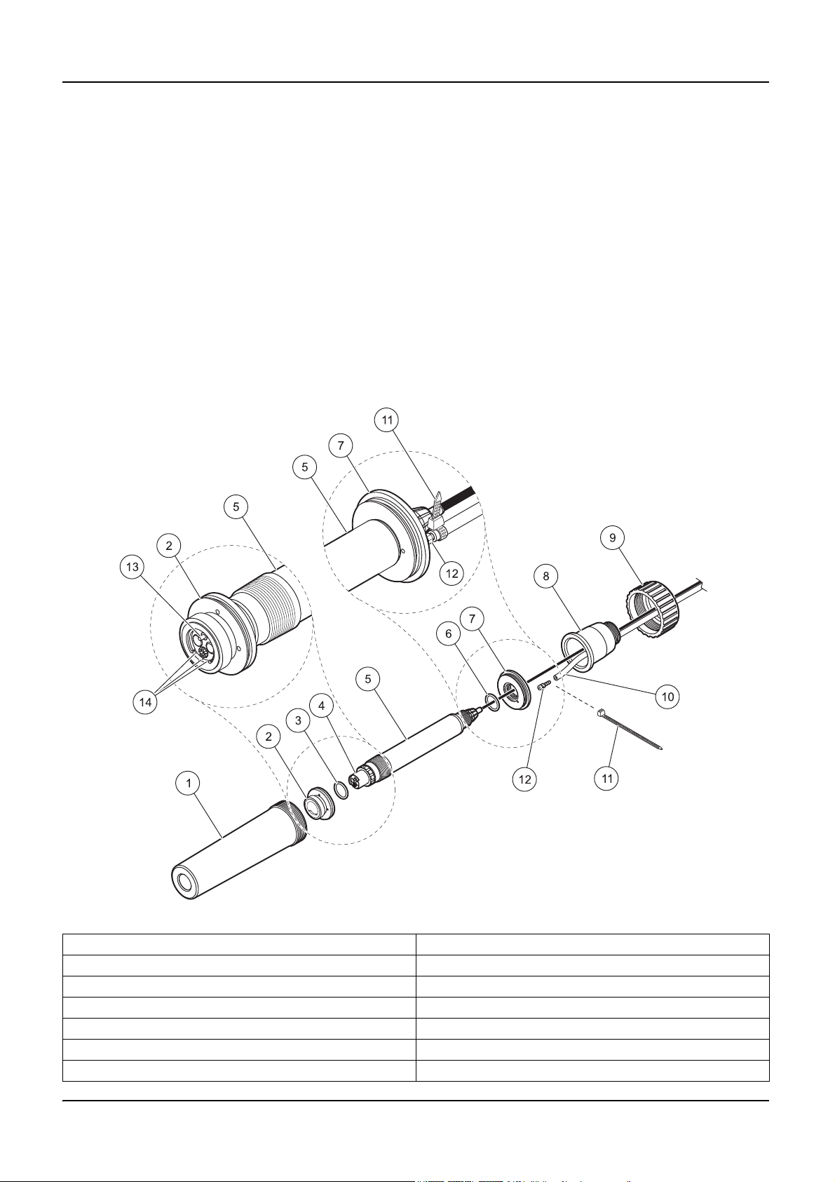
Refer to Figure 4 on page 4 and the following instructions for installation.
1. Slide the O-ring (item 6) and the sleeve insert (item 7) over the sensor cable.
2. Put the O-ring over the thread of the sensor and attach the sleeve insert to the sensor.
3. Put the male fitting (item 12) into the sleeve insert (item 7). Hand-tighten to secure.
4. Put the air tubing
(item 11).
1
Use pressure and UV resistant tube with an inner diameter of 6 mm.
1
(item 10) into the male fitting and secure it using the cable-tie
3
Page 4
Cleaning Unit
5. Slide the O-ring (item 3) from the cleaning insert (item 2) set onto the sensor cartridge
(item 4).
6. Put the cleaning insert into the sensor cartridge. Make sure that the air outlet openings
(item 14) are opposite of the temperature sensor (item 13).
7. Put the sensor (item 5) into the sleeve (item 1).
8. Slide the adapter (item 8) over the sensor cable and the air tubing (item 10).
9. Slide the union nut (item 9) over the sensor cable and the air tubing.
10. Install all the parts and hand-tighten the union nut to secure.
11. Mount the cleaning unit on the 45° adapter. Refer to the Instruction Sheet supplied
with the Hand Rail Mounting.
12. Connect the system to the controller and the High Output Air Blast and configure the
system. Refer to Relay configuration on page 5.
Figure 4 Assembly of the cleaning unit
1 Sleeve 8 Adapter, 1.5 inch NPT external thread
2 Cleaning insert, (with 2 pre-assembled O-rings) 9 Union nut
3 O-ring 10 Air tubing
4 Sensor cartridge 11 Cable tie
5 Sensor 12 Male fitting
6 O-ring 13 Temperature sensor
7 Sleeve insert, (with 2 pre-assembled O-rings) 14 Air outlet openings
4
Page 5

Compressor configuration
CAUTION
Ensure the cleaning unit is disconnected from the compressed air during
installation and service work.
Refer to the High Output Air Blast System User Manual for more information.
Relay configuration
To operate the compressor or an external valve (on the usage of an external supply of
compressed air), use the relay settings of the sc controller (RTC function of the relay).
Cleaning Unit
5
Page 6

Contact Information
HACH Company
World Headquarters
P.O. Box 389
Loveland, Colorado
80539-0389 U.S.A.
Tel (800) 227-HACH
(800) -227-4224
(U.S.A. only)
Fax (970) 669-2932
orders@hach.com
www.hach.com
HACH LANGE GMBH
Willstätterstraße 11
D-40549 Düsseldorf
Tel. +49 (0)2 11 52 88-320
Fax +49 (0)2 11 52 88-210
info@hach-lange.de
www.hach-lange.de
DR. BRUNO LANGE AG
Juchstrasse 1
CH-8604 Hegnau
Tel. +41(0)44 9 45 66 10
Fax +41(0)44 9 45 66 76
info@hach-lange.ch
www.hach-lange.ch
Repair Service in the
United States:
HACH Company
Ames Service
100 Dayton Avenue
Ames, Iowa 50010
Tel (800) 227-4224
(U.S.A. only)
Fax (515) 232-3835
HACH LANGE LTD
Pacific Way
Salford
GB-Manchester, M50 1DL
Tel. +44 (0)161 872 14 87
Fax +44 (0)161 848 73 24
info@hach-lange.co.uk
www.hach-lange.co.uk
HACH LANGE FRANCE
S.A.S.
33, Rue du Ballon
F-93165 Noisy Le Grand
Tél. +33 (0)1 48 15 68 70
Fax +33 (0)1 48 15 80 00
info@hach-lange.fr
www.hach-lange.fr
Repair Service in Canada:
Hach Sales & Service
Canada Ltd.
1313 Border Street, Unit 34
Winnipeg, Manitoba
R3H 0X4
Tel (800) 665-7635
(Canada only)
Tel (204) 632-5598
Fax (204) 694-5134
canada@hach.com
HACH LANGE LTD
Unit 1, Chestnut Road
Western Industrial Estate
IRL-Dublin 12
Tel. +353(0)1 46 02 5 22
Fax +353(0)1 4 50 93 37
info@hach-lange.ie
www.hach-lange.ie
HACH LANGE SA
Motstraat 54
B-2800 Mechelen
Tél. +32 (0)15 42 35 00
Fax +32 (0)15 41 61 20
info@hach-lange.be
www.hach-lange.be
Repair Service in
Latin America, the
Caribbean, the Far East,
Indian Subcontinent, Africa,
Europe, or the Middle East:
Hach Company World
Headquarters,
P.O. Box 389
Loveland, Colorado,
80539-0389 U.S.A.
Tel +001 (970) 669-3050
Fax +001 (970) 669-2932
intl@hach.com
HACH LANGE GMBH
Hütteldorferstr. 299/Top 6
A-1140 Wien
Tel. +43 (0)1 9 12 16 92
Fax +43 (0)1 9 12 16 92-99
info@hach-lange.at
www.hach-lange.at
DR. LANGE NEDERLAND
B.V.
Laan van Westroijen 2a
NL-4003 AZ Tiel
Tel. +31(0)344 63 11 30
Fax +31(0)344 63 11 50
info@hach-lange.nl
www.hach-lange.nl
HACH LANGE APS
Åkandevej 21
DK-2700 Brønshøj
Tel. +45 36 77 29 11
Fax +45 36 77 49 11
info@hach-lange.dk
www.hach-lange.dk
HACH LANGE LDA
Av. do Forte nº8
Fracção M
P-2790-072 Carnaxide
Tel. +351 214 253 420
Fax +351 214 253 429
info@hach-lange.pt
www.hach-lange.pt
HACH LANGE KFT.
Hegyalja út 7-13.
H-1016 Budapest
Tel. +36 (06)1 225 7783
Fax +36 (06)1 225 7784
info@hach-lange.hu
www.hach-lange.hu
HACH LANGE D.O.O.
Fajfarjeva 15
SI-1230 Domžale
Tel. +386 (0)59 051 000
Fax +386 (0)59 051 010
info@hach-lange.si
www.hach-lange.si
HACH LANGE AB
Vinthundsvägen 159A
SE-128 62 Sköndal
Tel. +46 (0)8 7 98 05 00
Fax +46 (0)8 7 98 05 30
info@hach-lange.se
www.hach-lange.se
HACH LANGE SP.ZO.O.
ul. Opolska 143 a
PL-52-013 Wrocław
Tel. +48 (0)71 342 10-83
Fax +48 (0)71 342 10-79
info@hach-lange.pl
www.hach-lange.pl
HACH LANGE S.R.L.
Str. Căminului nr. 3
Sector 2
RO-021741 Bucureşti
Tel. +40 (0) 21 205 30 03
Fax +40 (0) 21 205 30 03
info@hach-lange.ro
www.hach-lange.ro
ΗΑCH LANGE E.Π.Ε.
Αυλίδος 27
GR-115 27 Αθήνα
Τηλ. +30 210 7777038
Fax +30 210 7777976
info@hach-lange.gr
www.hach-lange.gr
HACH LANGE S.R.L.
Via Riccione, 14
I-20156 Milano
Tel. +39 02 39 23 14-1
Fax +39 02 39 23 14-39
info@hach-lange.it
www.hach-lange.it
HACH LANGE S.R.O.
Lešanská 2a/1176
CZ-141 00 Praha 4
Tel. +420 272 12 45 45
Fax +420 272 12 45 46
info@hach-lange.cz
www.hach-lange.cz
HACH LANGE
8, Kr. Sarafov str.
BG-1164 Sofia
Tel. +359 (0)2 963 44 54
Fax +359 (0)2 866 04 47
info@hach-lange.bg
www.hach-lange.bg
HACH LANGE E.P.E.
27, Avlidos str
GR-115 27 Athens
Tel. +30 210 7777038
Fax +30 210 7777976
info@hach-lange.gr
www.hach-lange.gr
HACH LANGE S.L.U.
Edif. Arteaga Centrum
C/Larrauri, 1C- 2ª Pl.
E-48160 Derio/Vizcaya
Tel. +34 94 657 33 88
Fax +34 94 657 33 97
info@hach-lange.es
www.hach-lange.es
HACH LANGE S.R.O.
Roľnícka 21
SK-831 07 Bratislava –
Vaj nory
Tel. +421 (0)2 4820 9091
Fax +421 (0)2 4820 9093
info@hach-lange.sk
www.hach-lange.sk
HACH LANGE SU
ANALİZ SİSTEMLERİ
LTD.ŞTİ.
Hilal Mah. 75. Sokak
Arman Plaza No: 9/A
TR-06550 Çankaya/ANKARA
Tel. +90 (0)312 440 98 98
Fax +90 (0)312 442 11 01
bilgi@hach-lange.com.tr
www.hach-lange.com.tr
HACH LANGE D.O.O.
Ivana Severa bb
42 000 Varaždin
Tel. +385 (0) 42 305 086
Fax +385 (0) 42 305 087
info@hach-lange.hr
www.hach-lange.hr
© Hach Lange GmbH, 2007–2009 Edition 2, Januar 2009 bb/ph/kt
 Loading...