

Page 1

DOC024.98.93054
POLYMETRON Model 8810 pH
Analyzer
09/2016, Edition 9
Allgemeines Benutzerhandbuch
Manuale di base per l'utente
Manuel d'utilisation de base
Manual básico del usuario
Podstawowa instrukcja obsługi
Manual de utilizare de bază
Basic User Manual
Page 2

English..............................................................................................................................3
Deutsch.......................................................................................................................... 27
Italiano............................................................................................................................ 53
Français......................................................................................................................... 79
Español........................................................................................................................ 104
Polski............................................................................................................................ 130
Română....................................................................................................................... 156
2
Page 3
Specifications
Specifications are subject to change without notice.
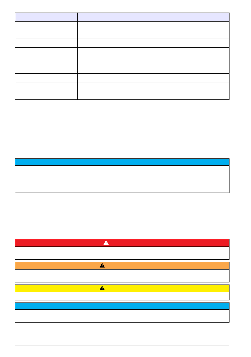
Specification Details
Ambient temperature 5 - 40 °C (41 - 104 °F)
Relative humidity 10 to 80%
Operating altitude From 0 to 2,000 m. (6,550 ft.) above sea level
Mains power supply 110/220/240 VAC, 50/60 Hz, ± 10%
Fuses: 110 to 120V, T630mAL250V; 220V to 240V, T1.25AL250V
Max. consumption 110 VA
Overvoltage category 2 (according to standard EN 61010-1)
Pollution degree 2
CE compliance EN61326-1: EMC Directive
Note: This is a Class A product. In a domestic environment this product may cause radio
interference in which case the user may be required to take adequate measures.
EN61010-1: LVD Directive
ETL approved ETL, conforming to UL 61010-1 and CSA 22.2 No. 61010-1
Korean certification
Compressed air 4 - 7 bar, filtered and dried
Rinse water pressure 0.5 - 6 bar
Reagents 10 liter storage canister (supplied)
Analog outputs Number: 2; 0 - 20 or 4 - 20 linear programmable
Alarms 2 x Relay (concentration); 1 x Warning or System alarm
Exchangeable sensors pH + reference electrode
Temperature compensation Pt100
Level control Sample; Reagents; Calibration solution; Chemical cleaning
Pumps Peristaltic, micro piston, pulse or volumetric pumps for calibration and conditioning
Tubing Tygon®; Polyethylene
Reagent consumption Application specific
Titration time Application specific
Cycle time Programmable up to 999 minutes
Accuracy < ± 2 to 4% (application specific)
Reproducibility < ± 2 to 4% (application specific)
User Guidance for EMC Class A Equipment
업무용을 위한 EMC 등급 A 장치에 대한
사용자 지침
사용자안내문
A 급 기기 ( 업무용 방송통신기자재 )
이 기기는 업무용 (A 급 ) 전자파적합기기로서 판매자 또는 사용자는 이 점을 주의
하시기 바라며 , 가정외의 지역에서 사용하는 것을 목적으로 합니다.
reagents
English 3
Page 4
Specification Details
Sample lines 1
Sample temperature 0 - 50 °C (32 - 122 °F)
Sample pressure 0.5 - 6 bar
Sample flow rate 40 - 300 liters/hour
Sample volume/cycle 200 - 1000 mL (adjustable)
Panel mount 743 x 482 x 122 mm (H x W x D); < 20 kg
Cabinet (IP 54) 1900 x 600 x 400 mm (H x W x D); < 100 kg
Maximum sound power level ≤ 80 dBA
General information
In no event will the manufacturer be liable for direct, indirect, special, incidental or consequential
damages resulting from any defect or omission in this manual. The manufacturer reserves the right to
make changes in this manual and the products it describes at any time, without notice or obligation.
Revised editions are found on the manufacturer’s website.
Safety information
N O T IC E
The manufacturer is not responsible for any damages due to misapplication or misuse of this product including,
without limitation, direct, incidental and consequential damages, and disclaims such damages to the full extent
permitted under applicable law. The user is solely responsible to identify critical application risks and install
appropriate mechanisms to protect processes during a possible equipment malfunction.
Please read this entire manual before unpacking, setting up or operating this equipment. Pay
attention to all danger and caution statements. Failure to do so could result in serious injury to the
operator or damage to the equipment.
Make sure that the protection provided by this equipment is not impaired. Do not use or install this
equipment in any manner other than that specified in this manual.
Use of hazard information
D A N GE R
Indicates a potentially or imminently hazardous situation which, if not avoided, will result in death or serious injury.
Indicates a potentially or imminently hazardous situation which, if not avoided, could result in death or serious
injury.
Indicates a potentially hazardous situation that may result in minor or moderate injury.
Indicates a situation which, if not avoided, may cause damage to the instrument. Information that requires special
emphasis.
4 English
W A R NI N G
C A U T I O N
N O T IC E
Page 5
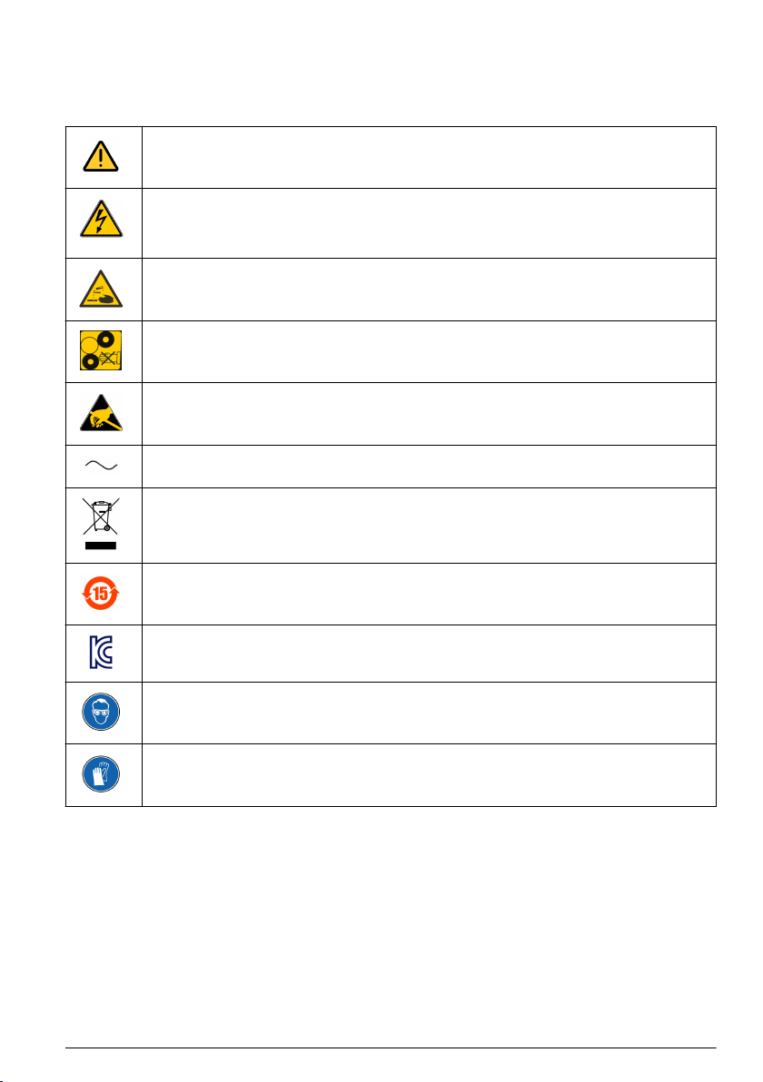
Precautionary labels
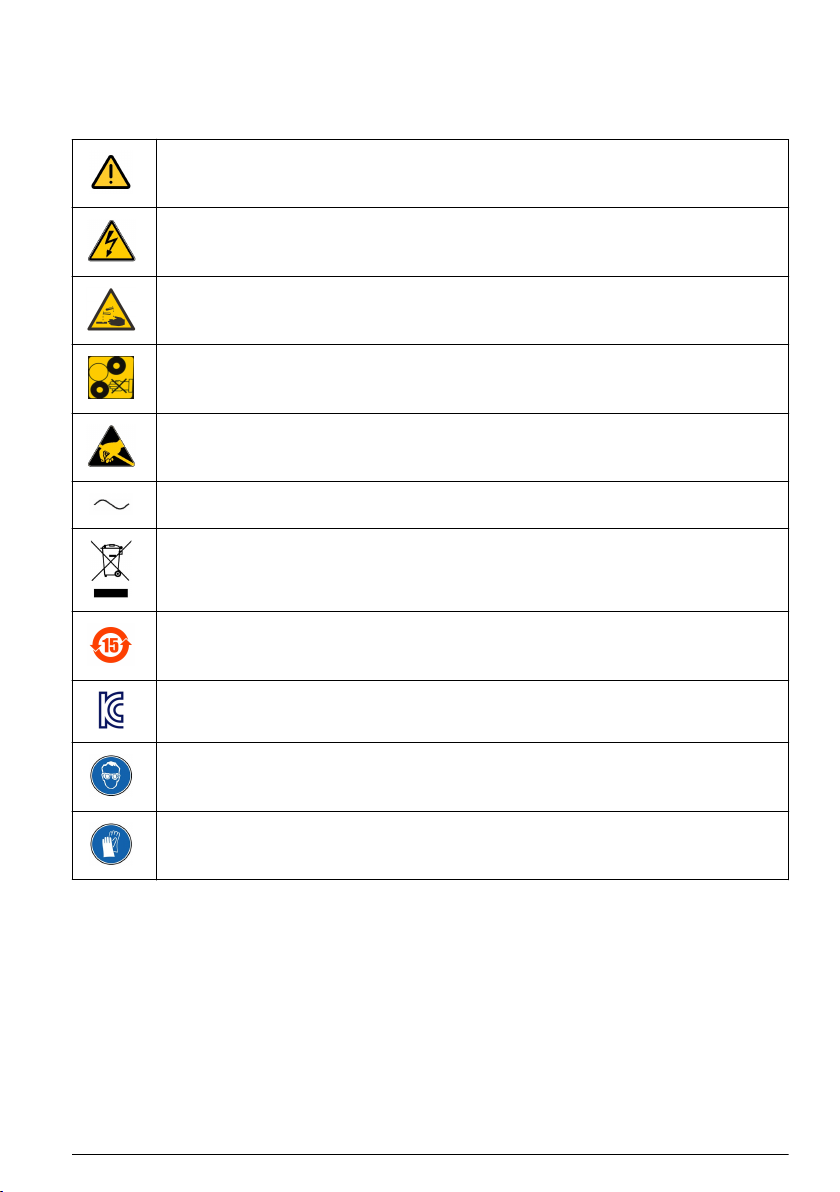
Read all labels and tags attached to the product. Personal injury or damage to the product could
occur if not observed. A symbol on the instrument is referenced in the manual with a precautionary
statement.
This symbol, when noted on a product, indicates a potential hazard which could cause serious
personal injury and/or death. The user should reference this instruction manual for operation and/or
safety information.
This symbol, when noted on a product enclosure or barrier, indicates that a risk of electrical shock
and/or electrocution exists and indicates that only individuals qualified to work with hazardous
voltages should open the enclosure or remove the barrier.
This symbol identifies the presence of a strong corrosive or other hazardous substance and a risk of
chemical harm. Only individuals qualified and trained to work with chemicals should handle
chemicals or perform maintenance on chemical delivery systems associated with the equipment.
Products marked with this symbol indicates a risk of finger pinch.
This symbol, when noted on the product, indicates the presence of devices sensitive to electrostatic
discharge and indicates that care must be taken to prevent damage to them.
This symbol, when noted on a product, indicates the instrument is connected to alternate current.
Electrical equipment marked with this symbol may not be disposed of in European domestic or
public disposal systems. Return old or end-of-life equipment to the manufacturer for disposal at no
charge to the user.
Products marked with this symbol indicates that the product contains toxic or hazardous substances
or elements. The number inside the symbol indicates the environmental protection use period in
years.
Products marked with this symbol indicates that the product conforms to relevant South Korean
EMC standards.
This symbol, if noted on the product, indicates the need for protective eye wear.
This symbol indicates the need for protective hand wear
Analyzer overview
The analyzer POLYMETRON Model 8810 ISE is a modular system used for ISE measurements in a
wide range of industrial on–line applications. The analyzer automatically collects on–line samples,
adds the applicable chemicals (such as reagents, buffers, masking agents) and completes the
analysis. The analyzer applies for heavy–duty, industrial on–line environments.
There is a standard panel-mounted version. A wall–mounted polyester cabinet and a free–standing
cabinet to house the analyzer with the necessary reagents are also available. Liquid modules are
installed below the electronic control unit for protection, easy access and service tasks. The hinged
panel tilts forward to access to the rear. Refer to Figure 1 for product overview.
English
5
Page 6
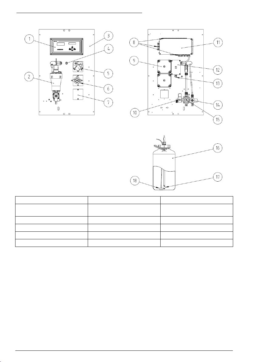
Figure 1 Front and rear view (panel mount illustrated)
1 Electronic unit 7 Space for additional pump 13 Power supply connection
2 Measurement chamber (see
Figure 2 on page 7)
3 19 inch panel 9 Reagent pump cover 15 Sample valve
4 Main switch 10 Compressed air valve 16 Reagent canister
5 Peristaltic pump 11 Electronic unit (rear) 17 Level detector
6 Micro piston pump 12 Power supply box 18 Tube weight
8 Input/Output connections 14 Rinse valve
Measurement chamber
Refer to Figure 2 for measurement chamber components.
6
English
Page 7
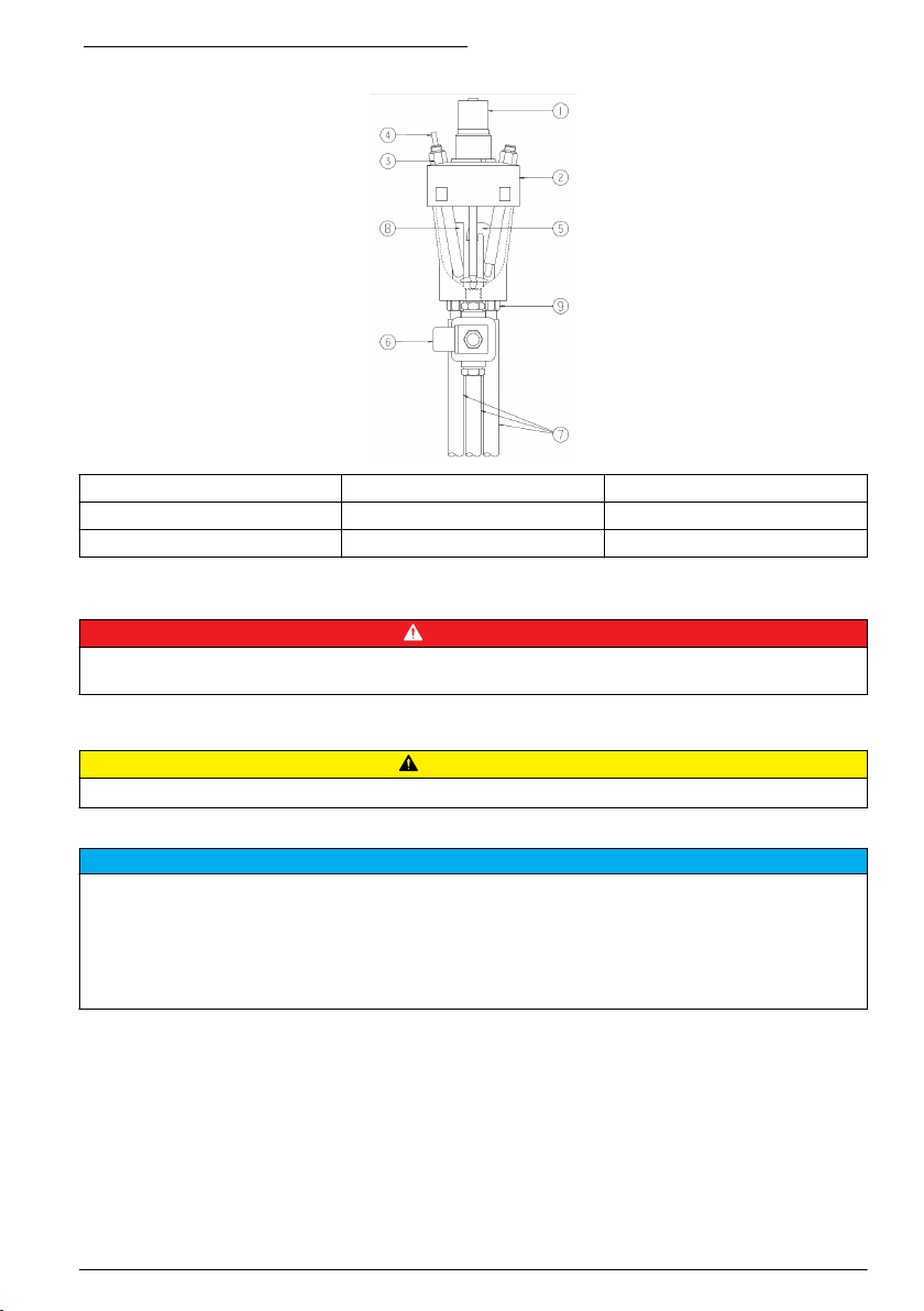
Figure 2 Measurement chamber components
1 Stirrer motor 4 Electrode cable 7 Drain tubing
2 Measurement chamber cover 5 Siphon 8 Overflow pipe
3 Electrode 6 Drain valve 9 Threaded fittings
Installation
D A N GE R
Multiple hazards. Only qualified personnel must conduct the tasks described in this section of the document.
Mains power should only be connected once installation has been completed and checked.
Mechanical installation
C A U T I O N
Multiple hazards. Only qualified personnel must conduct the tasks described in this section of the document.
Mounting the analyzer
The analyzer should be mounted as near as possible to the sample inlet, and should be located in an easily
accessible area to facilitate periodic checking of the sample flow rate, and for regular maintenance. In an
environmental enclosure that supplies protection from precipitation and direct sunlight, good ventilation and
temperature control if installed outdoors. Wherever the analyzer is to be mounted, it is important to note that it
must be placed in an upright position with the electronic unit (No. 1 in Figure 1 on page 6) at the top. It is
recommended to use a spirit level to ensure that the analyzer is correctly positioned and not leaning to one side
or forward. This is essential to guarantee the accuracy of the analyzer.
Panel mounting
This model is designed as a 19 inch (48.26 cm) rack system. Delivery includes six M6 screws for
mounting the panel onto a rack. All internal connections are factory prepared. Canisters for reagents
can be fitted onto an optional storage tray.
Wall mounting
All internal connections are factory prepared. Cables and tubing are threaded through the cable
glands located on the bottom right side of the cabinet. Canisters for reagents can be fitted onto an
optional storage tray.
N O T IC E
English
7
Page 8
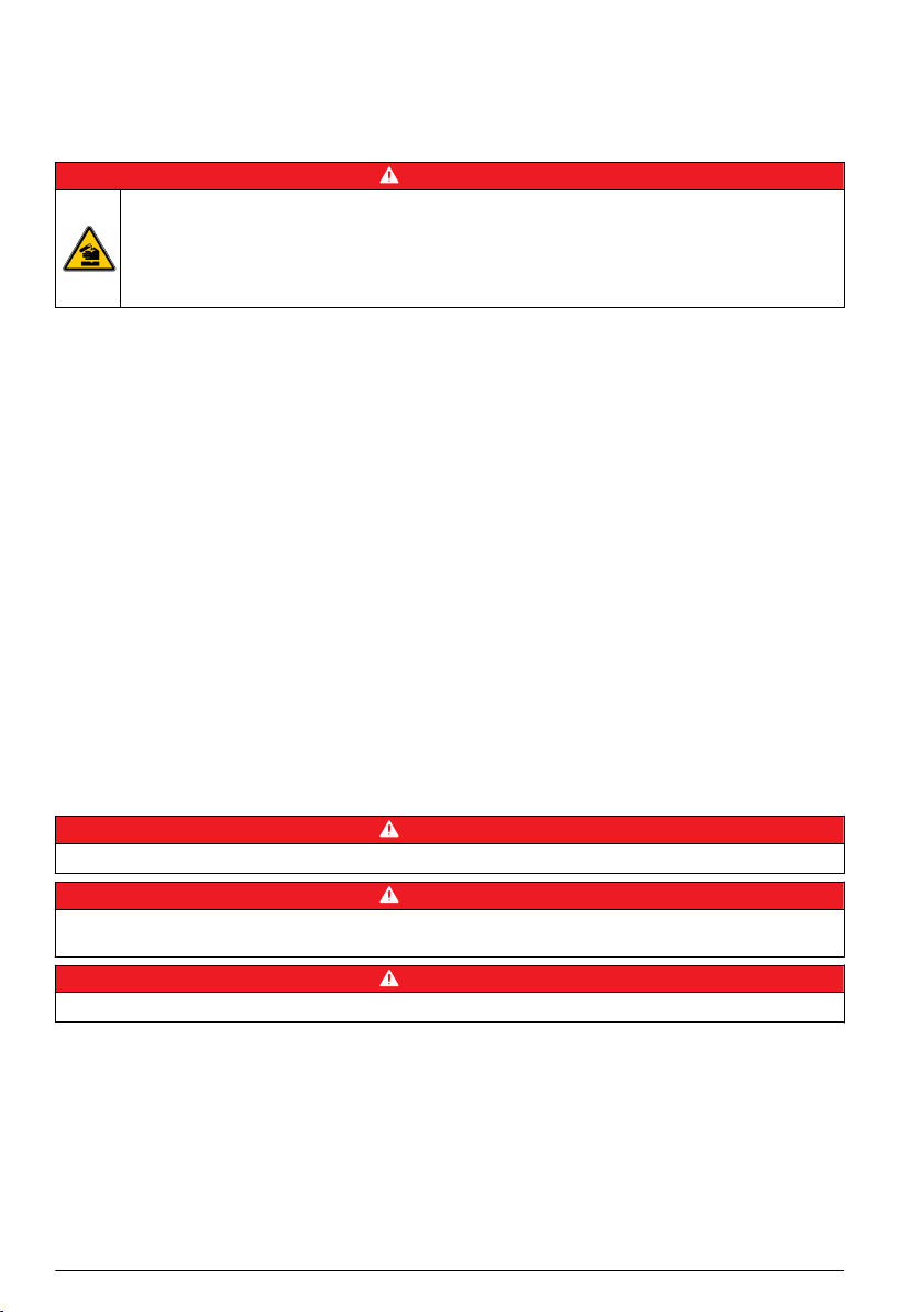
To open the cabinet, push the handle lid upwards, press the lock button, then open the door with a
45° left turn of the handle. To access the cabinet interior, remove the knurled screw on the right side
of the panel and carefully turn the panel sideways to the left taking care not to squeeze any tubing.
Hydraulic connections
D A N GE R
Chemical or biological hazards. If this instrument is used to monitor a treatment process and/or chemical
feed system for which there are regulatory limits and monitoring requirements related to public health,
public safety, food or beverage manufacture or processing, it is the responsibility of the user of this
instrument to know and abide by any applicable regulation and to have sufficient and appropriate
mechanisms in place for compliance with applicable regulations in the event of malfunction of the
instrument.
Sample
The sample enters the analyzer through a 12/14 mm hose (No. 15 in Figure 1 on page 6). Flow rate
should be between 40 and 300 liters/hour under a pressure of 0.5 to 6 bar.
Rinse water
The rinse water enters the analyzer through a 6/8 mm hose (No. 14 in Figure 1 on page 6). Water
pressure must be between 1 and 6 bar.
Reagents
The reagent containers are connected to the pumps according to the instructions corresponding to
the application.
Drain
The analyzed sample is drained at atmospheric pressure through a 12 mm hose (No. 7 in Figure 2
on page 7) delivered with the analyzer for initial startup. Make sure that no backflow occurs in this
tube or the other two drainage tubes (overflow No. 8 in Figure 2 on page 7 and siphon No. 5 in
Figure 2 on page 7).
Note: With the cabinet model, all three tubes drain into a receptacle with a 50 mm outlet.
Compressed air connection
The analyzer requires dry and filtered compressed air at a pressure of 4 to 7 bar. It should be
supplied to the valve (No. 10 in Figure 1 on page 6) using a suitable plastic tube of 4/6 mm diameter.
Electrical installation
D A N GE R
Multiple hazards. Only qualified personnel must conduct the tasks described in this section of the document.
Electrocution hazard. Always make sure the analyzer is turned off and power is disconnected before making
electrical connections.
Electrocution hazard. Protective Earth Ground (PE) connection is required.
Wiring procedures and cable preparation
The following procedure must be followed for all cables connecting peripherals (e.g. pumps, level
detectors, alarms, etc.) with the electronic unit (No. 11 in Figure 1 on page 6). Some cables will be
supplied ready for use. Other cables which are supplied locally by the user must be prepared
according to the procedure explained in Cable preparation on page 9 before connecting to the
electronic unit.
8
English
D A N GE R
D A N GE R
Page 9
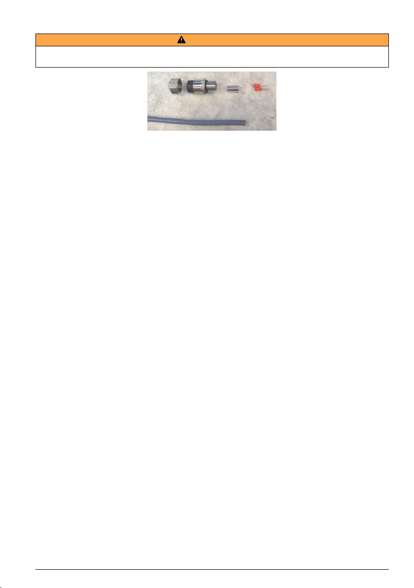
Cable preparation
W A R NI N G
To conform with security standards and to respect the EMC compliancy of the analyzer, this procedure must be
followed for all user supplied cables before connecting them to the electronic unit of the analyzer.
Materials required:
• Shielded cable (diameter minimum 4.5 mm - maximum 6 mm) with 2 or 3 wires depending on
function (RS232 = 3 wires, Alarm = 2 wires, etc.)
• Metal cable gland
• Grounding ferrule
• 2 or 3 protective plugs for the exposed wires
• Clamp for the grounding ferrule
• Crimping pliers for the protective plugs
English 9
Page 10
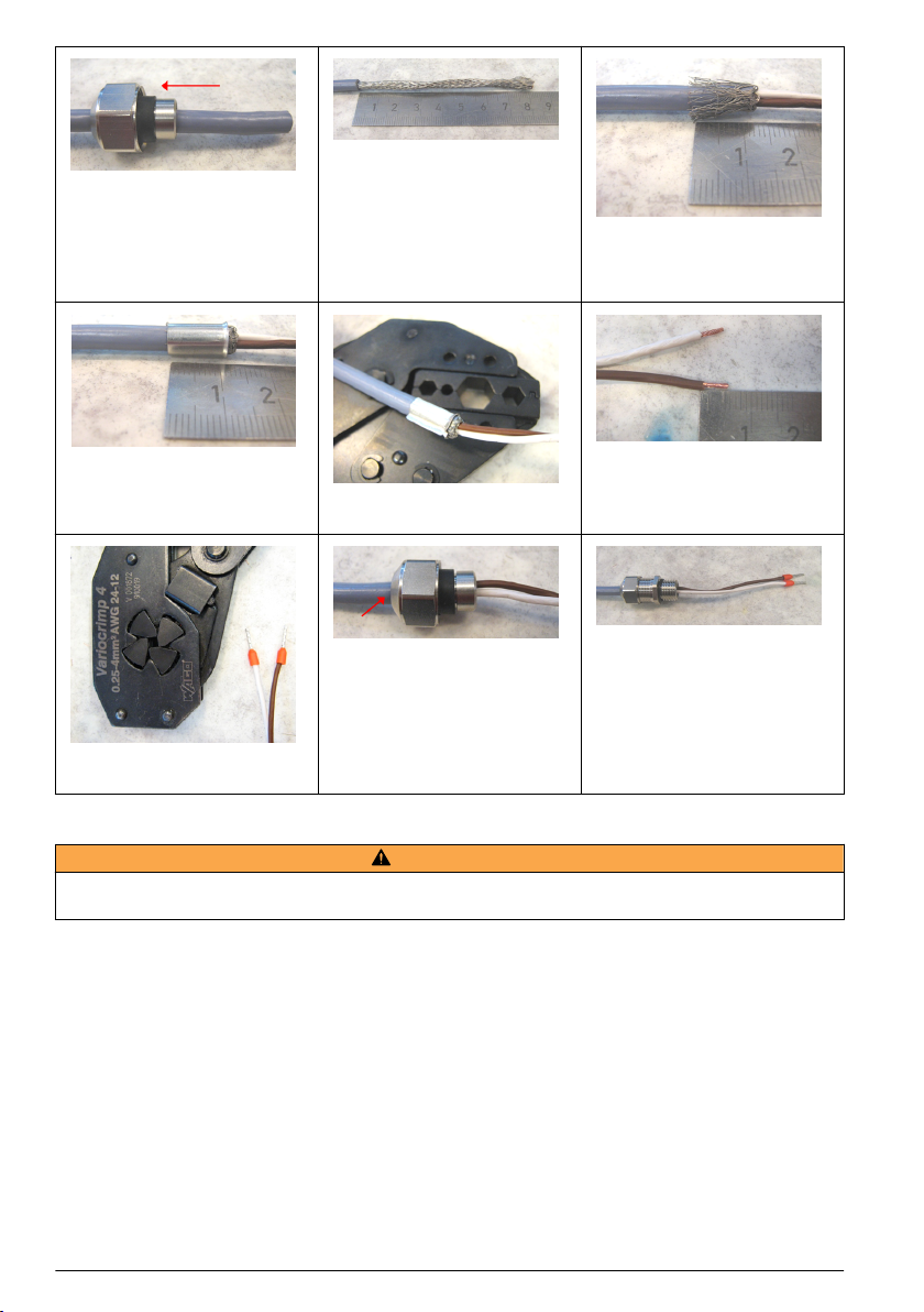
1. Place the nut and metal seal of
the cable gland onto the shielded
cable.
2. Remove 8 cm of the outer
cabling to reveal the braided
shielding.
3. Remove all but 12 mm of the
shielding to reveal the interior
wires, then roll the remainder of
the shielding back over the cable.
4. Insert the grounding ferrule over
the shielding.
7. Use the crimping pliers to attach
the protective plugs to the wires.
5. Use the clamp to fix the ferrule
securely to the cable.
8. Bring the metal shield up over
the ferrule and lock the two
together making sure the ferrule is
not exposed at the cable end of
the shield. Bring up the nut to
cover the shield.
6. Remove 5 mm of the external
insulation of the wires.
9. Pass the threaded part of the
cable gland over the wires and
screw into the nut on the cable.
The cable is now ready to be
connected following the procedure
described in Connecting
peripherals on page 10.
Connecting peripherals
W A R NI N G
To conform with security standards and to respect the EMC compliancy of the analyzer, this procedure must be
followed for connecting all peripherals to the electronic unit of the analyzer.
10 English
Page 11
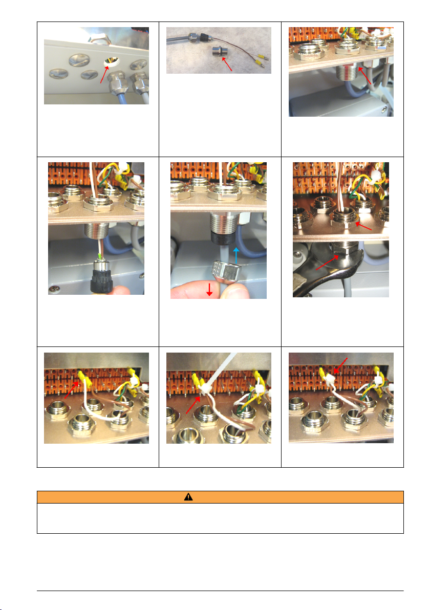
1. Select an unused opening
nearest to the cable connection on
the electronic board. Remove the
screw and nut combination and set
aside the screw for later use.
2. Take the cable, unscrew the
threaded part and remove it.
3. Screw the threaded part into the
electronic unit opening selected in
step 1 using the nut removed in
step 1 to secure in place.
4. Pass the rest of the cable
through the gland.
7. Connect the wires to the correct
terminals.
5. Pull the cable slightly with one
hand until the inner shield comes
into contact with the gland. Tighten
the nut onto the gland with the
other hand.
8. Secure the wires with a cable
tie.
6. Tighten the nut with a wrench to
secure in place. It may be
necessary to use a second wrench
to hold the top nut in place.
9. Cut the cable tie as near as
possible to the wires.
Electrode connections
W A R NI N G
To conform with security standards and to respect the EMC compliancy of the analyzer, this procedure must be
followed when connecting selective, reference, combined and temperature electrodes to the electronic unit of the
analyzer.
Before being connected to the terminal block of the measurement board, electrode cables must pass
through ferrite blocks to minimize the risk of outside interferences that could cause erroneous
measurement data.
English
11
Page 12
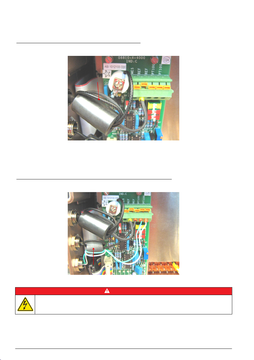
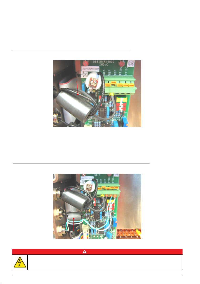
For the selective or combined electrode, install the cable gland and pass the cable of into the
electronic unit in the same way as for all other cables (as described in Connecting peripherals
on page 10). Once both wires (measurement and shield) are in place, pass them both through the
ferrite block. Make a loop by passing them through a second time before connecting them to their
respective inputs as illustrated in Figure 3.
Figure 3 Selective or combined electrode connection
For the reference electrode (not applicable in the case of a combined electrode) and the temperature
sensor, install the cable glands and pass the cables into the electronic unit in the same way as for all
other cables (as described in Connecting peripherals on page 10). Once the reference electrode wire
and the two temperature sensor wires are in place, pass them all through the second ferrite block.
Make a loop by passing them through a second time before connecting them to their respective
inputs as illustrated in Figure 4 (the temperature sensor has no polarity).
Figure 4 Reference electrode and temperature sensor connections
Mains power supply
Electrocution hazard. Always remove power to the instrument before making electrical connections.
12 English
D A N GE R
Page 13
D A N GE R
Electrocution hazard. Protective Earth Ground (PE) connection is required.
D A N GE R
Electrical shock and fire hazards. Make sure to identify the local disconnect clearly for the conduit
installation.
W A R NI N G
Potential Electrocution Hazard. If this equipment is used outdoors or in potentially wet locations, a
Ground Fault Interrupt device must be used for connecting the equipment to its mains power source.
C A U T I O N
Multiple hazards. Only qualified personnel must conduct the tasks described in this section of the
document.
N O T IC E
Install the device in a location and position that gives easy access to the disconnect device and its operation.
The analyzer is factory configured to either 110/120 VAC or 220/240 VAC. Make sure to connect the correct
power supply to the analyzer.
N O T IC E
Connect equipment in accordance with local, state or national electrical codes. Obey all codes and
regulations for wiring. Install cables into the instrument enclosure through the supplied cable glands.
Use screened and screen earthed cable for the mains connection. The mains wire specifications are:
diameter between 7 and 9.5 mm, 3 cores, 10 Amps minimum current rating, between 1 mm
2
(AWG18) and 2.5 mm2 (AWG14) minimum CSA (Cross Sectional Area). For all other signal
connections use screened instrument cable. Use also screen earthed cable for the signal
connections.
Note: Equipment intended for permanent connection to the MAINS must have provision for connection of a wiring
system in accordance with ANSI/NFPA 70, NEC, with CSA C22.1
Make sure that a 2 pole circuit breaker with a minimum breaking capcity of 20 A is installed in the
power line. Install a local disconnect for the instrument within 3 m (10 ft) of the instrument. Put a label
on the disconnect that identifies it as the main disconnect device for the instrument.
When the wiring of the system is completed, do the steps that follow to energize the system:
1. Open the power supply box (No. 12 in Figure 1 on page 6).
2. Pass the power cable through the cable gland and connect the earth, neutral and live wires to
terminals 1, 2 and 3 respectively as indicated in Figure 5.
English
13
Page 14
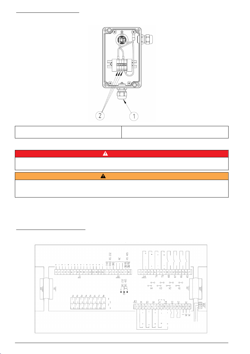
Figure 5 Power supply box
1 Mains power cable gland 2 Connection terminals (1 = Earth, 2 = Neutral, 3 =
Live)
Input/Output connections
D A N GE R
Electrocution hazard. Always make sure the analyzer is turned off and power is disconnected before making any
of the connections in this section.
To conform with security standards and to respect the EMC compliancy of the analyzer, follow the procedures
defined in Wiring procedures and cable preparation on page 8 for all connections to the electronic unit of the
analyzer.
The electronic unit (No. 11 in Figure 1 on page 6) must be opened from the rear to make these
connections. Unscrew the four screws holding the unit rear panel and gently swing open from left to
right. Refer to Figure 6 for terminal locations and the following tables for the functions.
Note: The terminal connectors diagram is also physically located on the rear of the electronic unit.
Figure 6 Terminal connectors
W A R NI N G
14 English
Page 15
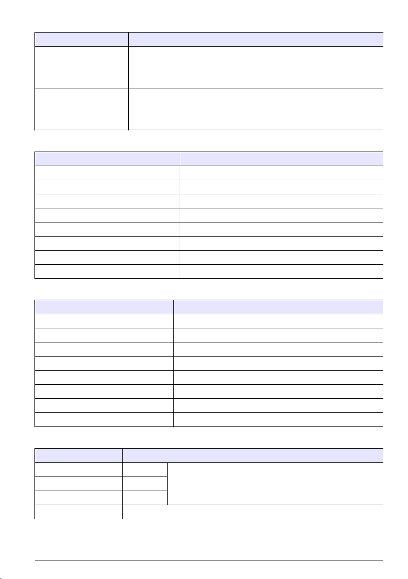
Table 1 Microprocessor board
Terminal Description
Relay configurations K5 - K8
X1 - X4
X5
• 2-3: Dry contact relay
• 1-2 and 3-4: 24 VDC
Serial interface
• 1-2: RS 232
• 2-3: RS 485
Table 2 Level detector and external commands (J1 - J8)
Terminal Use
J1 Start / Standby
J2 External sample
J3 Not used
J4 Conditioning solution
J5 Titration solution
J6 Calibration solution
J7 Chemical cleaning
J8 Sample
Table 3 Analog outputs (J9)
Terminal Use
1-2 Analog output 1
3-4 Analog output 2
5-6 Analog output 3
7-8 Analog output 4
9-10 Analog output 5
11-12 Analog output 6
13-14 Analog output 7
15-16 Analog output 8
Table 4 Serial interface (J10)
Terminal Use
1 TXD
RS 232 user configured with X5 2 RXD
3 GND
4, 5, 6, 7, 8 Not used
English 15
Page 16
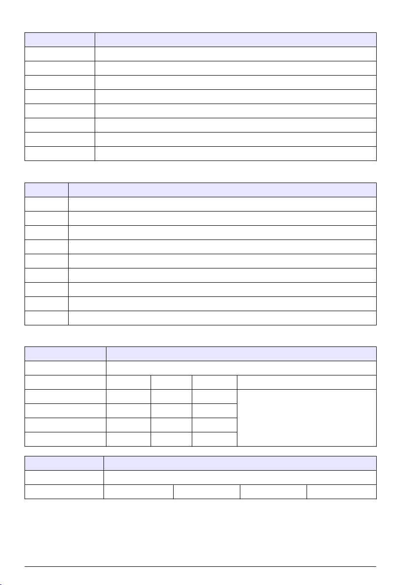
Table 5 Accessories 1 (J13)
Terminal Use
1-11 Heating system
2-3 Mixer
4-5 Rinse valve
6-7 Flush valve
8-9 Sample valve
12-13 Alarm 2
14-15 Alarm 1
16-17-18 System alarm (16-17 for NO or 16-18 for NC)
Table 6 Accessories 2 (J14)
Terminal Use
1-11 (8-10) Automatic calibration or external sample pump (connect 8 and 10 and set jumper X4 at 2-3)
2-3 Not used
4-5 Chemical cleaning valve
6-7 Dilution valve
8-9 Not used
10-11 Pump 4
12-13 Pump 3 (X3 set at 1-2 and 3-4)
14-15 Pump 2 (X2 set at 1-2 and 3-4)
16-17 Pump 1 (X1 set at 1-2 and 3-4) / Automatic calibration
Table 7 Pump functions 1 - 4
CAL AUTO YES or MANUAL YES
Jumper X4 X4 set at 2-3 and a strap between 8 and 10 of J14
Pump 1 Pump 2 Pump 3 Pump 4
1 titrant / 1 cond. Titrant 1 Cond 1
1 titrant / 2 cond. Titrant 1 Cond 1 Cond 2
2 titrants / 1 cond. Titrant 1 Cond 1 Titrant 2
2 titrants / 2 cond. Titrant 1 Cond 1 Titrant 2
CAL AUTO NO and MANUAL NO
Jumper X4 X4 set between 1-2 and 3-4 and no strap between 8 and 10 of J14
Pump 1 Pump 2 Pump 3 Pump 4
CAL AUTO or OTHER SAMPLE
16 English
Page 17
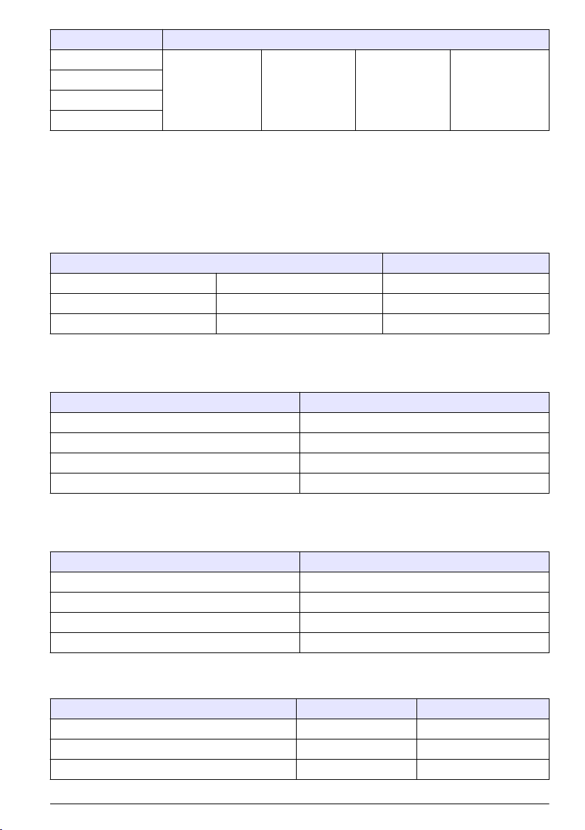
CAL AUTO NO and MANUAL NO
1 titrant / 1 cond.
1 titrant / 2 cond.
2 titrants / 1 cond.
2 titrants / 2 cond.
Titrant 1 Cond 1 Cond 2 Titrant 2
Alarms
Refer also to Figure 6 on page 14 and Table 5 on page 16. Alarm threshold relays (K2 and K3) are
set to normally open (NO). The system alarm relay (K1) can be set to normally open (terminals
16 and 17) or normally closed (terminals 16 and 18).
Analog outputs
Refer also to Figure 6 on page 14 and Table 3 on page 15. The analog outputs 0-20 mA or 4-20 mA
are galvanically insulated. The following table shows the allocation of the different outputs:
Analyzer
I out 1 Terminal 1-2 of J9 Measurement channel
I out 2 Terminal 3-4 of J9 Measurement potential
I out 3 Terminal 5-6 of J9 Not used
Sample level detector
Refer also to Figure 6 on page 14 and Table 2 on page 15. The reactor is equipped with a sample
level detector. Wire the connection to J8 as follows:
J8 Terminal number Color
1 Brown
2 Green
3 Yellow
4 White
Reagent level detector
Refer also to Figure 6 on page 14 and Table 2 on page 15. Each reagent canister is equipped with a
level detector. For each reagent, wire the connections to J4, J5, J6 and J7 as follows:
J4, J5, J6 and J7 Terminal number Color
1 Not used
2 Not used
3 Brown
4 White
RS232 connection
Refer also to Figure 6 on page 14 and Table 4 on page 15. Wire the connection to J10 as follows:
J10 Terminal number DB9 Plug DB25 Plug
1 (TXD) RXD: 2 RXD: 2
2 (RXD TXD: 3 TXD: 3
3 (GND) COM: 5 COM: 7
English 17
Page 18
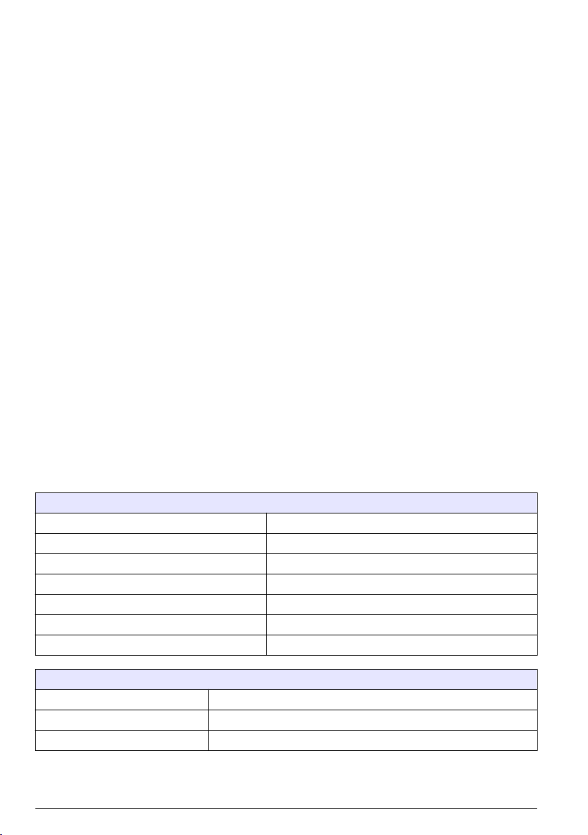
The 8810 configuration is:
• Speed: 9600 baud
• Data: 8 bits
• Stop bit: 2
• Parity: none
On startup the analyzer sends the name and software version:
• ANALYZER 8810 : 00 : 00 : 00 :
• pH X.XX : 00 : 00 : 00 :
In measurement mode, the analyzer sends the following data:
• Titration HH : MM : SS
• M1 XXXXEXX XX.X°C XXX for the first final point
• M2 XXXXEXX XX.X°C XXX for the second final point
• M3 XXXXEXX XX.X°C XXX for the differential between the two final points
Where:
• MX XXXXEXX = concentration measurement value
• XX.X°C = temperature
• XXX = value of the potential
In graph plotting mode, the analyzer sends the following data:
• Plotting HH : MM : SS
• P : XX.X°C XXX
Where:
• XX.X°C = temperature
• XXX = pH value
Where appropriate, the analyzer also sends the following messages with a time stamp (HH : MM :
SS):
ACTIONS
Cleaning Chemical cleaning
Stopped Analyzer stopped
Fix-time Time between two cycles
Standby Analyzer in standby
AUTO SYS CAL Automatic calibration
PROCESS SYS CAL Process calibration
MANUAL SYS CAL Manual calibration
SYSTEM ERRORS
LEVEL SAMPLE Sample missing from measuring cell
OVER TITR TIME Titration time is too long
ERROR CALIB Automatic calibration error
18 English
Page 19
WARNINGS
LEVEL REAGENT Titration reagent missing
LEVEL COND Conditioning reagent missing
LEVEL CALIB Calibration solution missing
LEVEL CLEANING Cleaning solution missing
RETURN PROCESS After an external sample measurement, this message indicates a return to process
SLOPE CALIB 1/2 Automatic calibration error
measurement
Additional accessories
Any accessories that have been purchased but that have not been factory installed, can be installed
now. Instructions for the installation and wiring are given in the full user manual.Once everything has
been installed, check the following in the measurement chamber:
• Nothing is in contact with the stirrer
• The upper part of the overflow pipe is about 2 cm above the siphon
• The level detector is about 1 cm below the bottom of the siphon inlet
• If not connected, connect the measuring electrode to the thicker cable and the reference electrode
to the thinner cable.
User interface
Front panel description
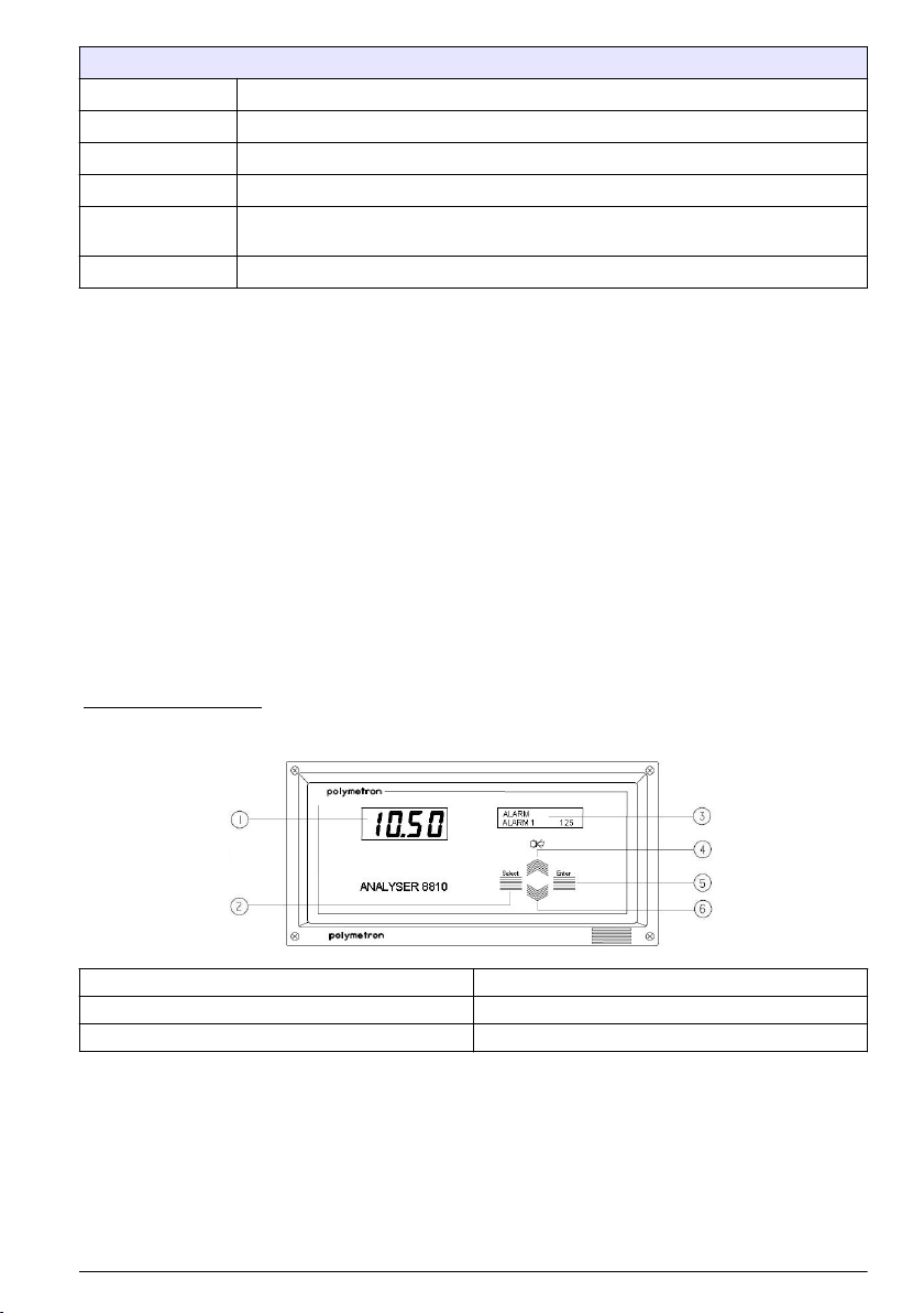
The interface is via a 4-key keyboard, a 4-digit numeric display and an alphanumeric display of 2lines of 16 characters.
Figure 7 Front panel
1 Numeric display 4 Scroll up key
2 Select key 5 Enter key
3 Alphanumeric display 6 Scroll down key
Function keys
• Enter: Invoke functions or confirm parameters.
• Select: Select menu options, adjust parameters, exit submenus, and switch between command
and operating mode.
• Scroll down: Adjust variables, scroll through displays in operating mode and submenus in
command mode.
• Scroll up: Same as scroll down but in reverse order, and cancel the system alarm.
English
19
Page 20

Analyzer modes
The analyzer functions in Operating mode or Command mode. In Operating mode the analyzer
performs standard actions such as measurement, calibration, etc. A limited number of parameters
can also be displayed using the scroll keys. In Command mode the analyzer can be programmed,
parameters displayed and analyzer functions tested. By default, the analyzer is in Command mode
when first switched on.
To enter Operating mode from Command mode, select START from the MAIN MENU.
To enter Command mode from Operating mode, press Select to display the STOP command, then
• if you only wish to display currently defined parameters, from the STOP command use the scroll
keys to select READING and press Enter for approximately 3 seconds.
• if you wish to program the analyzer or test analyzer functions, from the STOP command press
Enter and then Enter again to confirm. Then use the scroll keys to select PROGRAMMING and
press Enter for approximately 3 seconds.
Displays
Numeric display: This display shows concentration (default), potential or temperature
measurements.
Alphanumeric display: This display provides messages on status and programming. Messages are
different according to the mode:
• Operating mode: The top line indicates units, measurement type and any activated alarms. The
bottom line indicates the analyzer status, e.g. calibration, titration, etc.
• Command mode: The top line indicates the main menu. The bottom line indicates submenus and
data settings.
Menu overview
MAIN MENU
The main menu gives access to the following functions:
• STOP - Pressing Enter causes the measurement process to stop immediately
• START - Pressing Enter initiates the measurement process
• STAND-BY - Pressing Enter puts the analyzer in standby
• PROGRAMMING - Program the analyzer (Command mode only)
• READING - View parameters (Operating mode only)
In PROGRAMMING or READING mode the following options can be selected using the scroll keys:
• MEASUREMENT - Titration parameters
• CALIBRATION - Calibrate the analyzer
• ANALOG-OUT - Analog output parameters
• ALARM - Alarm limit parameters
• SEQUENCE - Measurement mode
• SERVICE - Check the analyzer and accessory operations
• CLEANING - Chemical cleaning parameters
• SAMPLE COND. - Sample conditioning parameters
• CAL PARAMETER - View the primary and last calibration details
• TIMING - Titration cycle parameters
• PM XXXX - System configuration (only available in PROGRAMMING mode and requires a valid
password)
Note: Some of the above options are only available if the relevant accessory has been installed.
20
English
Page 21

System configuration (PM XXXX option)
Refer also to any Installation Procedure documents delivered with the analyzer for application
specific information.
1. Select PM XXXX with the scrolling keys and press Enter. Using the Select key to move from one
digit to the next, enter the passcode and press Enter.
Option Description
APPLICATION Select your application from the list available.
UNIT Select the unit of concentration from the list available. Selecting USER allows you to define
Adjust ADC This option is reserved for HACH LANGE service technicians.
Adjust Iout Select the output type (0-20mA or 4-20mA). Place a multimeter in series with the analog
OPTION From the list available, select YES for those that have been installed/required and NO for
your own, and requires a 5 character description.
output and make any small adjustments to the signal as required.
those not installed/required.
Note: Some of the options require additional hardware installation (e.g. AUTO SYS CAL,
CLEANING, HEATING, etc.). For correct operation of the analyzer, any hardware
installations must have been completed prior to commissioning.
Titration parameters (MEASUREMENT option)
For ACID and BASE applications, only one set of parameters are required. For other applications,
two sets of parameters are required.
1. Select MEASUREMENT with the scrolling keys and press Enter.
Option Description
PRE-ENDPT1/2 Enter the pre-endpoint value.
ENDPT1/2 Enter the endpoint value.
Calibration (CALIBRATION option)
Calibration in READING mode
The CALIBRATION option is available for viewing the calibration parameters. Scroll through the list
of parameters as they are displayed.
Calibration in PROGRAMMING mode
Three options are available:
• PRIMARY CALIBRATION
• SYSTEM CALIBRATION
• ELECTRODE CALIBRATION
PRIMARY or SYSTEM calibration
A primary calibration is made in the factory and is the reference for all other calibrations. In general,
this should not need to be renewed unless significant system modifications have been made e.g.
electrode replacement.
English
21
Page 22

The process for a PRIMARY or SYSTEM calibration is the same.
1. From the CALIBRATION menu, select PRIMARY CAL or SYSTEM CAL with the scrolling keys
and press Enter.
Option Description
MANUAL SYS CAL This calibration requires a laboratory prepared calibration solution(s) with known
PROCESS SYS CAL This calibration uses the process solution, with known concentration, as the
AUTO SYS CAL This is only available if this option has been installed.
concentration.
calibration solution.
Manual calibration
1. Select MANUAL SYS CAL and press Enter.
2. FILL CAL SOL. is displayed. Pour the calibration solution into the measurement chamber and
press Enter.
3. CONC SOL: XXXXX is displayed. Enter the concentration as a five digit number with no decimal
point, or a four digit number with decimal point. Press Enter to confirm.
4. If the 2 INDEP PTS or the TWO REAGENTS option has been selected, the second point
concentration is required. Enter the concentration of the second solution and press Enter.
Process calibration
1. Select PROCESS SYS CAL and press Enter.
2. CONC SOL: XXXXX is displayed. Enter the concentration as a five digit number with no decimal
point, or a four digit number with decimal point. Press Enter to confirm.
3. If the 2 INDEP PTS or the TWO REAGENTS option has been selected, the second point
concentration is required. Enter the concentration of the second solution and press Enter.
Automatic calibration
This is only available if the analyzer has this option installed. It allows for an automatic calibration at
pre-programmed intervals, using a calibration solution of known concentration.
Note: If this is the first time this option is being selected, select NO to IMMEDIATE at step 3 in order to input
required additional parameters.
1. Check the content of the calibration solution cannister. One calibration uses 250 to 300 mL of the
calibration solution so the capacity of a standard canister will allow 30 to 40 calibrations.
2. Select AUTO SYS CAL and press Enter. IMMEDIATE is displayed. Select YES or NO followed
by Enter. If YES is selected an automatic calibration will start immediately. No more input is
required.
3. If NO is selected, enter the FREQUENCY of calibrations. This is the number of titrations between
each automatic calibration.
4. CONC SOL: XXXXX is displayed. Enter the concentration as a five digit number with no decimal
point, or a four digit number with decimal point. Press Enter to confirm.
5. If the 2 INDEP PTS or the TWO REAGENTS option has been selected, the second point
concentration is required. Enter the concentration of the second solution and press Enter.
6. INJ. TIME is displayed. Enter the injection time of the calibration solution in seconds and confirm
with Enter.
ELECTRODE calibration
The electrode calibration requires two buffer solutions of known concentration to effect a 2-point
calibration. The buffer solutions should have different pH concentrations of between 1 and 9, or close
22
English
Page 23
to that of the application. The buffer 1 solution should have the lowest pH value and buffer 2 the
highest.
1. From the CALIBRATION menu, select ELECTRODE CAL with the scrolling keys and press
Enter.
Option Description
2 POINT Press Enter to confirm a 2-point calibration.
FILL BUFFER 1 Fill the measurement chamber with the first buffer solution and press Enter.
BUFFER 1: XXXXX Enter the pH value of the first buffer solution and press Enter.
FILL BUFFER 2 Fill the measurement chamber with the second buffer solution and press Enter.
BUFFER 2: XXXXX Enter the pH value of the second buffer solution and press Enter.
Calibration results
In PRIMARY CAL the calibration is always considered correct and will be used as a reference for the
other calibrations. The slope is considered as 100%.
For other calibrations the new slopes are compared to the values of the primary calibration. If the
new slope values are within 70-130% of the current values they will be considered valid and used for
all future measurement calculations.
If the new slope values are between 50-70% or 130-150% of the current values it is necessary to
CONFIRM the new values. Select YES or NO and press Enter. If YES is selected the new values are
used for all future measurement calculations. If NO is selected (or if the new slope values are <50%
or >150% of the current values) the message ERROR CALIB is displayed. Press Enter to continue.
CAL ERROR indicates that the calibration is in error. Select RETRY to repeat the calibration or
ABORT to abort the calibration.
In automatic calibration the instrument does not require any confirmation. However, if the slope
deviation is <50% or >150% of the current values a warning message SLOPE CALIB ! appears on
the display.
Analog outputs (ANALOG-OUT option)
The analyzer has two analog outputs which are allocated according to the application:
Application Analog Output 1 Analog Output 2
ACID Acid concentration pH when starting a titration
BASE Base concentration pH when starting a titration
FREE/TOTAL ACID FREE TOTAL
FREE/TOTAL BASE FREE TOTAL
2p-m p 2p-m
x(p-m) m x(p-m)
x(m-p) p x(m-p)
1. Select ANALOG-OUT with the scrolling keys and press Enter.
Option Description
START I1/2 Enter the value that corresponds to the 0/4mA current output.
END I1/2 Enter the value that corresponds to the 20mA current output.
Conc Test the output by sending the current corresponding to the last measured value.
English 23
Page 24

Option Description
Full Test the output by sending the maximum current of 20mA.
Zero Test the output by sending the minimum current of 0 or 4mA depending on the analyzer setup.
Note: You can only exit this menu when the option Conc is displayed.
Set the alarms and thresholds (ALARM option)
The analyzer has three alarms which are allocated according to the definition of WARNING/R1:
WARNING/R1 set to NO WARNING/R1 set to YES
System alarm System and warning alarm System alarm only
Alarm 1 Alarm 1 Warning alarm
Alarm 2 Alarm 2 Alarm 1 and 2
1. Select ALARM with the scrolling keys and press Enter.
Option Description
SYS.ALARM ON/OFF Activate or deactivate the system alarm.
WARNING/R1 YES/NO Define the alarm allocation (see table above).
ALARM 1/2 ON/OFF Activate or deactivate alarms 1 and 2.
ALARM 1/2 XXX/XXX If activated, define what measurement triggers the alarm (application specific).
ALARM 1/2 HIGH/LOW If activated, define if the trigger is a high or low measurement value.
ALARM 1/2 XXX Enter the threshold value. If the alarm is set to HIGH any measured value above
this threshold will trigger the alarm, or if the alarm is set to LOW any measured
value below this threshold will trigger the alarm.
Measurement mode (SEQUENCE option)
Define the measurement mode.
1. Select SEQUENCE with the scrolling keys and press Enter. Use the scrolling keys to select the
required mode.
Option Description
FIX TIME A fixed interval between measurements. The interval is defined in Measurement cycle parameters
LOOP Continuous measurement. No further input is required.
PLOT pH Select this if a titration curve needs to be plotted. Enter the START pH and END pH values
(TIMING option) on page 25.
(between 0 and 14) that define the 0/4mA and 20mA outputs. If the TWO REAGENTS option has
been chosen, define which reagent will be used to define the slope.
Test analyzer and accessories (SERVICE option)
Check various physical options (e.g. pumps) are working correctly. The option to view the version
number of the latest installed software is also available from the list.
1. Select SERVICE with the scrolling keys and press Enter.
2. Select the option to test from the list available and set to ON to start it, check it functions
correctly, and then set back to OFF to stop it.
24
English
Page 25

Chemical cleaning (CLEANING option)
This option is displayed only if the CLEANING option has been activated.
Define the parameters required for a chemical cleaning of the system.
1. Select CLEANING with the scrolling keys and press Enter.
Option Description
FREQUENCY Enter the number of measurements between each chemical cleaning.
SPRINKLER Define the duration (in seconds) for rinsing the measurement chamber.
REAG. INJ Define the duration (in seconds) that the cleaning solution is injected into the measurement
RESIDENC. Define the duration (in seconds) that the cleaning solution remains in the measurement
chamber.
chamber.
Sample conditioning (SAMPLE COND option)
This option is displayed only if the SAMPLE COND option has been activated.
Define the parameters required for conditioning the sample prior to measurement. It is possible to
define 1 or 2 conditioning reagents.
1. Select SAMPLE COND with the scrolling keys and press Enter.
Option Description
REAGENT 1/2 OFF/ON Set to ON if the conditioning is made using this reagent.
INJ. REAG. 1/2 Define the duration (in seconds) that the reagent is injected into the measurement
TIME REAG. 1/2 Define the duration (in seconds) that the reagent remains in the sample before
chamber.
measurement.
View calibration details (CAL PARAMETER option)
This option lets you view the details of the primary and last calibrations made by the analyzer.
1. Select CAL PARAMETER with the scrolling keys and press Enter.
2. Use the scroll keys to select LAST CAL or PRIMARY CAL, then scroll through the details by
pressing Enter.
Measurement cycle parameters (TIMING option)
Define the parameters for each measurement.
1. Select TIMING with the scrolling keys and press Enter.
Option Description
SAMPLE TIME Define the time (in seconds) the sample is injected into the measuring chamber.
SPRINKLER N Define the number of rinses required.
SPRINKLER t Define the duration (in seconds) of each rinse.
INJECT TIME Define the time (in seconds) the reagent is injected into the sample.
DELAY TIME Define the time (in seconds) between each injection.
English 25
Page 26
Option Description
CYCLE TIME Define the duration (in minutes) of the measurement cycle.
LIM. TIT. t Define the maximum duration (in minutes) of a titration. If this time is exceeded a system
alarm is triggered
Maintenance
D A N GE R
Electrocution hazard. Always make sure the analyzer is turned off and power is disconnected before carrying out
any maintenance on the analyzer.
General
For periodic maintenance, all the elements are freely accessible on the front panel.
For installation of accessories and specialized service work the analyzer is easily accessible from all
sides with some simple manipulations. The electronic control and analytical units can be accessed
and removed after opening the front of the analyzer with the special key provided.
Maintenance schedule
The schedule is dependent on the type of application. In general we can say that a monthly
maintenance is required to perform the following tasks:
• Check all reagent and chemical containers. Refill if necessary
• Disconnect the tubing and replace the other way round
• Every 2 months replace all the tubing
• Check the measurement chamber and electrodes for any deposits. Clean if visibly contaminated
• Check all tube connections for any leaks
• Check the system is running smoothly. Calibrate if necessary
Cleaning and decontamination
The analyzer does not normally require any cleaning or decontamination.
If needed, clean the exterior of the instrument with a moist cloth and a mild soap solution. Never use
cleaning agents such as turpentine, acetone or similar products to clean the instrument, including the
display and any accessories.
Shutdown
Stopping the measurement cycle
Select STOP in the main menu and press Enter. The message stopped is displayed.
Short shutdown (e.g. weekend)
Select STAND BY in the main menu and press Enter to put the system in a defined standby
condition. The measurement chamber is drained, rinsed, and refilled with rinse water.
Prolonged shutdown
If the system is shut down for a long period of time the electrodes must be cleaned and the
measurement chamber rinsed. It is preferable to then remove the electrodes and store them in a
buffer solution until the system is restarted. Under no condition must the electrodes be left in an
empty measurement chamber as this will cause them to dry out and become damaged. Finally, turn
the power off.
26
English
Page 27
Spezifikationen
Die Spezifikationen können ohne Vorankündigung Änderungen unterliegen.
Spezifikation Details
Umgebungstemperatur 5 - 40 °C (41 - 104 °F)
Relative Feuchtigkeit 10 bis 80%
Betriebshöhe Von 0 bis 2.000 m (6550 ft) über dem Meeresspiegel
Stromversorgung 110/220/240 VAC, 50/60 Hz, ± 10%
Sicherungen: 110 bis 120 V, T630mAL250V, 220 bis 240 V, T1.25AL250V
Max. Verbrauch 110 VA
Überspannungskategorie 2 (gemäß Standard EN 61010-1)
Verschmutzungsgrad 2
CE-Konformität EN61326-1: EMV-Richtlinie
Hinweis: Dies ist ein Produkt der Klasse A. In Haushaltsumgebungen kann dieses Produkt
Funkstörungen verursachen, die dazu führen können, dass der Benutzer Gegenmaßnahmen
ergreifen muss.
EN61010-1: Niederspannungsrichtlinie
ETL-gelistet ETL, entspricht UL 61010-1 und CSA 22.2 Nr. 61010-1
Koreanisch-Zertifizierung
Druckluft 4 - 7 bar, gefiltert und trocken
Spülwasserdruck 0,5 - 6 bar
Reagenzlösungen 10-Liter-Kanister (Lieferumfang)
Analoge Ausgänge Anzahl: 2; 0 - 20 oder 4 - 20 linear programmierbar
Alarme 2 x Relais (Konzentration); 1 x Warnung oder Systemalarm
Austauschbare Sensoren pH + Referenzelektrode
Temperaturkompensation Pt 100
Füllstandkontrolle Probe, Reagenzlösung, Kalibrierungslösung, chemische Reinigung
Pumpen Schlauchpumpe, Mikrokolbenpumpe, Impulspumpe oder volumetrische Pumpe
Schlauchleitungen Tygon®, Polyethylen
Reagenzlösungsverbrauch Anwendungsspezifisch
Titrationszeit Anwendungsspezifisch
Zykluszeit Programmierbar bis max. 999 Minuten
Genauigkeit < ± 2 bis 4% (anwendungsabhängig)
User Guidance for EMC Class A Equipment
업무용을 위한 EMC 등급 A 장치에 대한
사용자 지침
사용자안내문
A 급 기기 ( 업무용 방송통신기자재 )
이 기기는 업무용 (A 급 ) 전자파적합기기로서 판매자 또는 사용자는 이 점을 주
의하시기 바라며 , 가정외의 지역에서 사용하는 것을 목적으로 합니다.
für die Konditionierung der Reagenzlösung
Deutsch 27
Page 28
Spezifikation Details
Reproduzierbarkeit < ± 2 bis 4% (anwendungsabhängig)
Probenleitungen 1
Probentemperatur 0 - 50 °C (32 - 122 °F)
Probendruck 0,5 - 6 bar
Probenflussrate 40 - 300 l/h
Probenvolumen/-zyklus 200 - 1000 ml (einstellbar)
Schalttafelmontage: 743 x 482 x 122 mm (H x B x T); < 20 kg
Gehäuse (IP54) 1900 x 600 x 400 mm (H x B x T); < 100 kg
Maximaler Schallleistungspegel ≤ 80 dBA
Allgemeine Informationen
Der Hersteller ist nicht verantwortlich für direkte, indirekte, versehentliche oder Folgeschäden, die
aus Fehlern oder Unterlassungen in diesem Handbuch entstanden. Der Hersteller behält sich
jederzeit und ohne vorherige Ankündigung oder Verpflichtung das Recht auf Verbesserungen an
diesem Handbuch und den hierin beschriebenen Produkten vor. Überarbeitete Ausgaben der
Bedienungsanleitung sind auf der Hersteller-Webseite erhältlich.
Sicherheitshinweise
H I N WE I S
Der Hersteller ist nicht für Schäden verantwortlich, die durch Fehlanwendung oder Missbrauch dieses Produkts
entstehen, einschließlich, aber ohne Beschränkung auf direkte, zufällige oder Folgeschäden, und lehnt jegliche
Haftung im gesetzlich zulässigen Umfang ab. Der Benutzer ist selbst dafür verantwortlich, schwerwiegende
Anwendungsrisiken zu erkennen und erforderliche Maßnahmen durchzuführen, um die Prozesse im Fall von
möglichen Gerätefehlern zu schützen.
Bitte lesen Sie dieses Handbuch komplett durch, bevor Sie dieses Gerät auspacken, aufstellen oder
bedienen. Beachten Sie alle Gefahren- und Warnhinweise. Nichtbeachtung kann zu schweren
Verletzungen des Bedieners oder Schäden am Gerät führen.
Stellen Sie sicher, dass die durch dieses Messgerät bereitgestellte Sicherheit nicht beeinträchtigt
wird. Verwenden bzw. installieren Sie das Messsystem nur wie in diesem Handbuch beschrieben.
Bedeutung von Gefahrenhinweisen
G E F AH R
Kennzeichnet eine mögliche oder drohende Gefahrensituation, die, wenn sie nicht vermieden wird, zum Tod oder
zu schweren Verletzungen führt.
Kennzeichnet eine mögliche oder drohende Gefahrensituation, die, wenn sie nicht vermieden wird, zum Tod oder
zu schweren Verletzungen führen kann.
Kennzeichnet eine mögliche Gefahrensituation, die zu geringeren oder moderaten Verletzungen führen kann.
Kennzeichnet eine Situation, die, wenn sie nicht vermieden wird, das Gerät beschädigen kann. Informationen, die
besonders beachtet werden müssen.
28 Deutsch
W A R NU N G
V O R SI C H T
H I N WE I S
Page 29
Warnaufkleber
Bitte lesen Sie alle Aufkleber und Schilder, die am Produkt angebracht sind. Die Nichtbeachtung
kann zu Verletzungen von Personen oder Beschädigungen des Produkts führen. Im Handbuch
werden auf die am Gerät angebrachten Symbole in Form von Warnhinweisen verwiesen.
Dieses Symbol auf einem Produkt zeigt eine potenzielle Gefahr an, die zu ernsthaften Verletzungen
und/oder zum Tod führen kann. Der Benutzer soll dieses Handbuch bei der Bedienung des Geräts
und/oder für Sicherheitsinformationen verwenden.
Dieses Symbol auf einer Verkleidung oder Schranke des Produkts weist auf die Gefahr von
Stromschlägen hin und macht darauf aufmerksam, dass ausschließlich für die Arbeit mit
gefährlichen Spannungen qualifiziertes Personal die Verkleidung öffnen oder die Schranke
entfernen sollte.
Dieses Symbol weist auf das Vorhandensein einer stark korrodierenden oder anderen gefährlichen
Substanz und auf Gefahren durch Chemikalien hin. Ausschließlich im Umgang mit Chemikalien
geschultes Personal darf Wartungsarbeiten am Zufuhrsystem vornehmen.
Bei Produkten, die mit diesem Symbol gekennzeichnet sind, besteht Verletzungsgefahr durch
Klemmen.
Dieses Symbol auf dem Produkt weist auf das Vorhandensein von Bauteilen hin, die durch
elektrostatische Entladungen gestört werden können und macht darauf aufmerksam, dass mit
Vorsicht vorgegangen werden muss, um Schäden an diesen Bauteilen zu vermeiden.
Dieses Symbol weist darauf hin, dass das Instrument an Wechselstrom angeschlossen werden
muss.
Elektrogeräte, die mit diesem Symbol gekennzeichnet sind, dürfen in der Europäischen Union nicht
als Haushaltsabfall oder in öffentlichen Abfallentsorgungssystemen entsorgt werden. Altgeräte
können ohne zusätzliche Kosten für den Verbraucher an den Hersteller für die Entsorgung
zurückgegeben werden.
Produkte, die mit diesem Symbol gekennzeichnet sind, enthalten toxische oder gefährliche
Substanzen oder Elemente. Die Ziffer in diesem Symbol gibt den Umweltschutzzeitraum in Jahren
an.
Produkte, die mit diesem Symbol gekennzeichnet sind, entsprechen den EMV-Standards
Südkoreas.
Dieses Symbol auf dem Produkt weist darauf hin, dass ein Augenschutz getragen werden muss.
Dieses Symbol weist darauf hin, dass Schutzhandschuhe getragen werden müssen.
Übersicht über den Analysator
Der ISE-Analysator PPOLYMETRON Modell 8810 ist ein modulares System für die ISE-Messung bei
vielen industriellen Online-Anwendungen. Der Analysator nimmt automatisch Online-Proben, fügt die
entsprechenden Chemikalien hinzu (Reagenzien, Puffer, Maskierungsmittel) und beendet die
Analyse. Der Analysator ist für raue, industrielle Online-Umgebungen gedacht.
Es ist eine Standardversion zur Schrankmontage erhältlich. Ein an der Wand befestigter Schrank aus
Polyester und ein freistehender Schrank zur Aufnahme der notwendigen Reagenzien im Analysator
sind ebenfalls erhältlich. Zum Schutz sind Flüssigmodule unter der elektronischen Einheit installiert,
für einfachen Zugang und unkomplizierte Wartungsarbeiten. Die Klappwand ist nach vorne gekippt,
um gut an die Rückseite zu gelangen. Eine Produktübersicht finden Sie in Abbildung 1.
Deutsch
29
Page 30
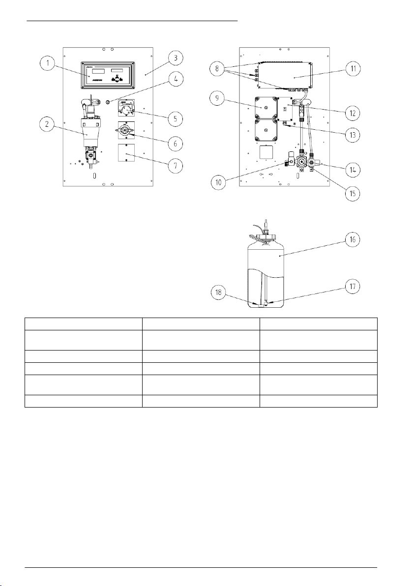
Abbildung 1 Vorder- und Rückansicht (Paneelmontage)
1 Bedien- und Anzeigefeld 7 Platz für eine zusätzliche Pumpe 13 Netzanschluss
2 Messungskammern (siehe
Abbildung 2 auf Seite 31)
3 19-Zoll-Paneel 9 Abdeckung Reagenzpumpe 15 Probenventil
4 Hauptschalter 10 Druckluftventil 16 Reagenzlösungskanister
5 Schlauchpumpe 11 Elektronische Einheit
6 Mikrokolbenpumpe 12 Netzanschlussdose 18 Schlauchgewicht
8 Anschlüsse für
Eingang/Ausgang
(Rückseite)
14 Spülventil
17 Füllstanddetektor
Messungskammer
In Abbildung 2 sind die Komponenten der Messungskammer dargestellt.
30
Deutsch
Page 31
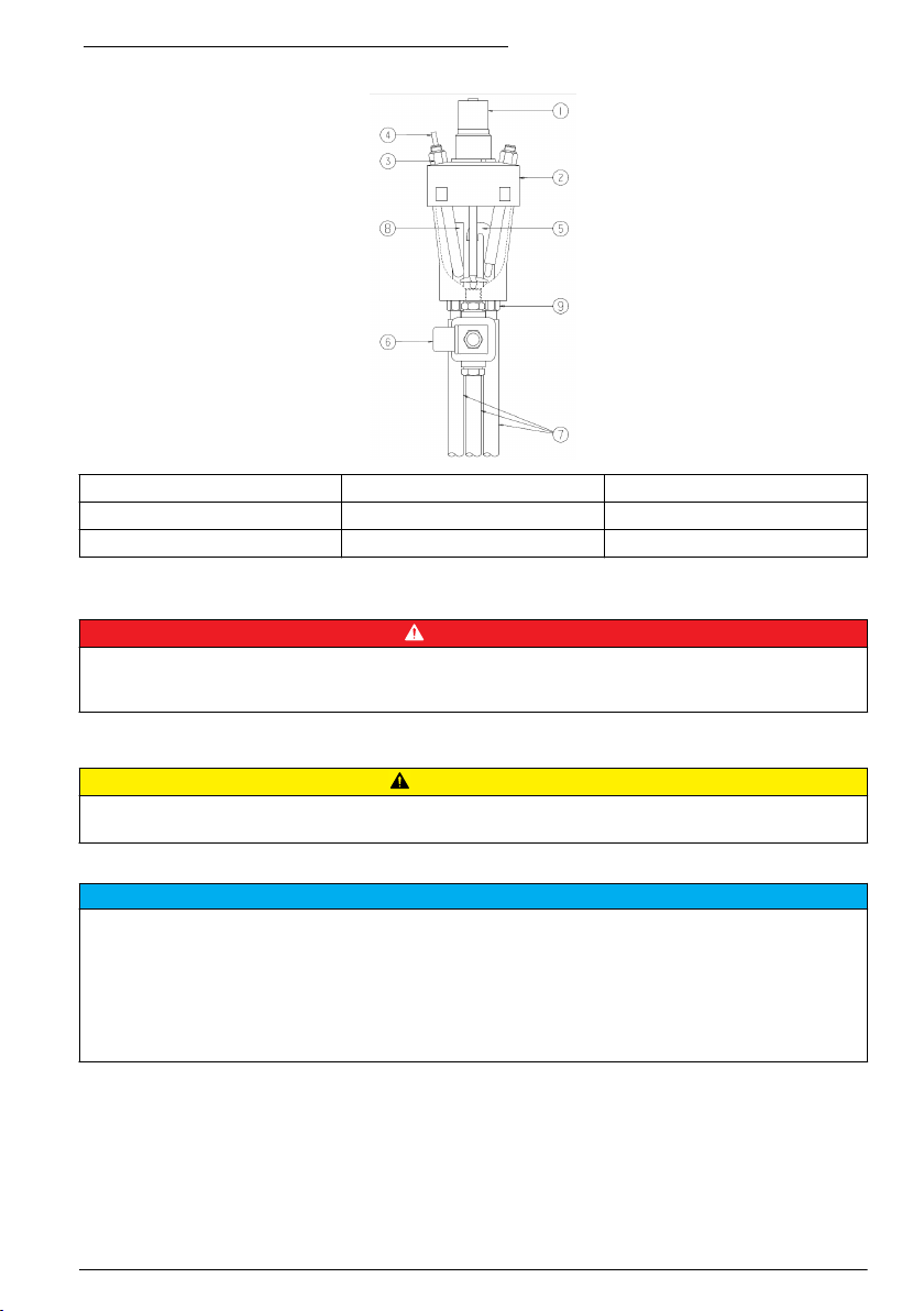
Abbildung 2 Komponenten der Messungskammer
1 Rührwerkmotor 4 Elektrodenkabel 7 Ablaufleitung
2 Abdeckung d. Messungskammer 5 Siphon 8 Überlaufleitung
3 Elektrode 6 Ablaufventil 9 Gewindemuffen
Installation
G E F AH R
Mehrere Gefahren. Nur qualifiziertes Personal sollte die in diesem Kapitel des Dokuments beschriebenen
Aufgaben durchführen. Die Stromversorgung darf erst angeschlossen werden, nachdem die die Installation
abgeschlossen und überprüft worden ist.
Mechanische Installation
V O R SI C H T
Mehrere Gefahren. Nur qualifiziertes Personal sollte die in diesem Kapitel des Dokuments beschriebenen
Aufgaben durchführen.
Installation des Analysators
Der Analysator muss so nah wie möglich an dem Probeneinlass installiert werden. Außerdem muss der
Aufstellungsbereich des Geräts leicht zugänglich sein, damit die periodischen Kontrollen der Probenflussrate und
die routinemäßige Wartung problemlos durchgeführt werden können. Bei Installation im Freien in einem Gehäuse
mit Schutz vor Niederschlägen und direkter Sonneneinstrahlung, mit guter Belüftung und Temperaturregelung.
Der Analysator muss aber auf jeden Fall immer vollkommen senkrecht und mit der elektronischen Einheit Nr. 1
auf Abbildung 1 auf Seite 30 oben installiert werden. Wir empfehlen, eine Wasserwaage zu verwenden, um
sicherzustellen, dass der Analysator ordnungsgemäß montiert wird und nicht zu einer Seite geneigt ist. Dies ist
von wesentlicher Bedeutung für die Gewährleistung der Präzision des Analysators.
Paneelmontage
Dieses Modell wurde als 19-Zoll-Rack-System (48,26 cm) entwickelt. Zum Lieferumfang gehören
sechs M6 Schrauben für die Befestigung des Paneels auf dem Rack. Alle internen Anschlüsse
wurden werkseitig erstellt. Kanister für Reagenzlösungen können auf einer zusätzlichen Ablage
(optional) befestigt werden.
H I N WE I S
Deutsch
31
Page 32
Wandmontage
Alle internen Anschlüsse wurden werkseitig erstellt. Die Kabel und Leitungen werden durch die
Führungen am Gehäuseboden rechts geführt. Kanister für Reagenzlösungen können auf einer
zusätzlichen Ablage (optional) befestigt werden.
Um das Gehäuse zu öffnen, schieben Sie den Griff der Abdeckung nach oben und drücken den
Verriegelungsknopf. Drehen Sie dann den Griff 45 Grad nach links, um die Tür zu öffnen. Für den
Zugriff auf das Geräteinnere entfernen Sie die Rändelschraube auf der rechten Seite des Paneels.
Drehen Sie dann das Paneel vorsichtig nach links. Achten Sie darauf, dass die Schlauchleitungen
nicht gequetscht werden.
Hydraulische Anschlüsse
G E F AH R
Chemische und biologische Risiken. Wird das Gerät dazu verwendet, ein Verfahren und/oder eine
chemische Zuleitung zu überwachen, für das vorgeschriebene Grenzwerte und
Überwachungsvorschriften im Bereich der öffentlichen Sicherheit, der Gesundheit oder im Bereich der
Lebensmittel- oder Getränkeherstellung bestimmt wurden, so unterliegt es der Verantwortung des
Benutzers des Geräts, alle solche Bestimmungen zu kennen und diese einzuhalten und für
ausreichende und entsprechende Vorsorgemaßnahmen zur Einhaltung der für den Fall einer
Fehlfunktion des Geräts bestehenden Bestimmung zu sorgen.
Probe
Die Probe fließt über einen 12-14 mm Schlauch (Nr. 15 in Abbildung 1 auf Seite 30) abgeleitet. Die
Flussrate sollte zwischen 40 und 300 l/h betragen und einen Druck zwischen 0,5 und 6 bar
aufweisen.
Spülwasser
Das Spülwasser fließt über einen 6-8 mm Schlauch (Nr. 14 in Abbildung 1 auf Seite 30) abgeleitet.
Der Wasserdruck muss zwischen zwischen 1 und 6 bar liegen.
Reagenzlösungen
Die Reagenzlösungsbehälter werden in Übereinstimmung mit den Anweisungen für die jeweilige
Anwendung an die Pumpen angeschlossen.
Abfluss
Die analysierte Probe wird mit Luftdruck über einen 12 mm Schlauch (Nr. 7 in Abbildung 2
auf Seite 31) abgelassen. Dieser Schlauch gehört zum Starterkit für die Erstinbetriebnahme des
Analysators. Hier und in den beiden anderen Abflussschläuchen (Überlauf Nr. 8 in Abbildung 2
auf Seite 31 und Siphon Nr. 5 in Abbildung 2 auf Seite 31) abgeleitet.
Hinweis: Bei dem Schrankmodell münden alle drei Schläuche in einen Auffangbehälter mit einem 50 mm Abfluss.
Druckluftanschluss
Die für den Analysator verwendete Druckluft muss sauber und trocken sein und einen Druck von
4 bis 7 bar aufweisen. Für die Zuführung das Ventil (Nr. 10 in Abbildung 1 auf Seite 30) und einen
passenden Plastikschlauch mit 4-6 mm Durchmesser verwenden.
Elektrische Installation
G E F AH R
Mehrere Gefahren. Nur qualifiziertes Personal sollte die in diesem Kapitel des Dokuments beschriebenen
Aufgaben durchführen.
Gefahr von Stromschlägen. Vor der Erstellung von elektrischen Anschlüssen muss der Analysator ausgeschaltet
und von der Netzversorgung getrennt werden.
Gefahr von Stromschlägen. Es ist eine Schutzerdung erforderlich.
32 Deutsch
G E F AH R
G E F AH R
Page 33
Verkabelung und Kabelvorbereitung
Bei Anschluss von Peripheriegeräten (z. B. Pumpen, Füllstanddetektoren, Alarme usw.) an die
elektronische Einheit (Nr. 11 in Abbildung 1 auf Seite 30) immer wie folgt verfahren. Einige Kabel
werden gebrauchsfertig geliefert. Andere Kabel, die der Gerätebetreiber selbst bereitstellt, müssen
vor dem Anschluss, wie in Vorbereitung der Kabel auf Seite 33 beschrieben, vorbereitet werden.
Vorbereitung der Kabel
W A R NU N G
Um die Konformität mit den Sicherheitsstandards zu gewährleisten und den EMV-Anforderungen des Analysators
zu entsprechen, müssen alle Kabel, die der Gerätetreiber selbst bereitstellt, für den Anschluss an die
elektronische Einheit wie folgt vorbereitet werden.
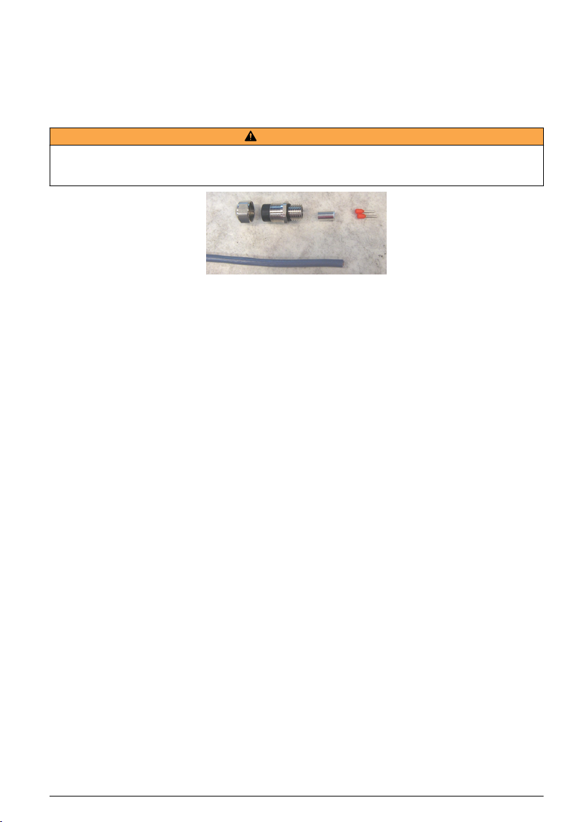
Erforderliches Material:
• Geschirmtes Kabel (Durchmesser min. 4.5 mm - max. 6 mm) je nach Funktion mit 2 oder
3 Drähten (RS232 = 3 Drähte, Alarm = 2 Drähte etc.)
• Kabeldurchführung aus Metall
• Erdungsring
• 2 oder 3 Schutzstecker für freiliegende Drähte
• Klemme für Erdungsring
• Krimpzange für Schutzstecker
Deutsch 33
Page 34
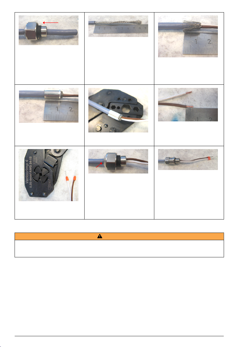
1. Ziehen Sie Mutter und
Metalldichtung der
Kabeldurchführung auf das
geschirmte Kabel.
2. Entfernen Sie 8 cm der äußeren
Kabelhülle, um das Schirmgeflecht
freizulegen.
3. Entfernen Sie bis aus 12 mm
das Schirmgeflecht, um die
inneren Kabel freizulegen. Ziehen
Sie das übrige Schirmgeflecht
über das Kabel nach hinten.
4. Schieben Sie den Erdungsring
über das Schirmgeflecht.
7. Schließen Sie die Schutzstecker
mit der Krimpzange an die Drähte
an.
5. Fixieren Sie den Ring mit der
Klemme.
8. Führen Sie die Metallisolierung
über den Erdungsring und
verbinden Sie beide fest
miteinander. Der Erdungsring darf
keinen Kontakt mit dem Kabelende
an der Schirmung haben. Ziehen
Sie die Mutter hoch, um die
Schirmung abzudecken.
6. Entfernen Sie 5 mm der
äußeren Kabelisolierung.
9. Führen Sie den gewindeten Teil
der Kabeldurchführung über die
Drähte und schrauben Sie ihn in
die Mutter auf dem Kabel. Das
Kabel kann jetzt, wie in
Peripheriegeräte anschließen
auf Seite 34 beschrieben,
angeschlossen werden.
Peripheriegeräte anschließen
W A R NU N G
Um die Konformität mit den Sicherheitsstandards zu gewährleisten und den EMV-Anforderungen des Analysators
zu entsprechen, verfahren Sie beim Anschluss von Peripheriegeräten an die elektronische Einheit des
Analysators wie folgt:
34 Deutsch
Page 35
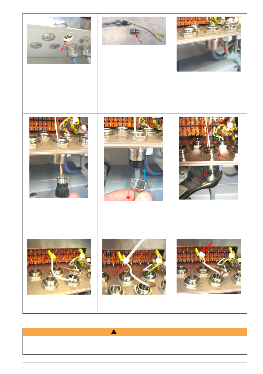
1. Wählen Sie eine noch nicht
verwendete Öffnung in
Übereinstimmung mit dem
Kabelanschluss auf der
Schalttafel. Entfernen Sie
Schraube und Mutter. Bewahren
Sie die Schraube sorgsam auf. Sie
muss später wiederverwendet
werden.
2. Nehmen Sie das Kabel, lösen
Sie das Gewindeteil und entfernen
Sie es.
3. Schrauben Sie das Gewindeteil
auf die Öffnung an der
elektronischen Einheit, die Sie in
Schritt 1 ausgewählt haben.
Verwenden Sie dazu die in Schritt
1 entfernte Mutter.
4. Führen Sie das Kabelende
durch die Verschraubung.
Schließen Sie die Kabel an die
korrekten Klemmen an.
5. Ziehen Sie leicht mit einer Hand
so lange an dem Kabel, bis der
Innenschutz die Verschraubung
berührt. Ziehen Sie jetzt die Mutter
auf der Verschraubung mit der
anderen Hand an.
Sichern Sie die Kabel mit einem
Kabelbinder.
6. Ziehen Sie Mutter fest mit einem
Schraubenschlüssel an.
Möglicherweise müssen Sie die
obere Mutter mit einem zweiten
Schraubenschlüssel blockieren.
Schneiden Sie die Kabelbinder so
nah wie möglich an den Kabeln
ab.
Elektroden anschließen
W A R NU N G
Um die Konformität mit den Sicherheitsstandards zu gewährleisten und den EMV-Anforderungen des Analysators
zu entsprechen, verfahren Sie beim Anschluss von selektiven Elektroden, Referenzelektroden, kombinierten
Elektroden und Temperaturelektroden an die elektronische Einheit des Analysators wie folgt:
Deutsch 35
Page 36
Vor dem Anschluss an die Klemmenleiste des Messboards müssen die Elektrodenkabel durch
Ferritklemmen geführt werden, um das Risiko von Interferenzen von außen, die zu fehlerhaften
Messdaten führen können, auf ein Minimum zu reduzieren.
Bei selektiven oder kombinierten Elektroden die Kabelverschraubung montieren und das Kabel wie
alle anderen Kabel in die elektronische Einheit (siehe Peripheriegeräte anschließen auf Seite 34)
führen. Wenn beide Kabel (Messung und Schirm) in Position sind, werden beide durch die
Ferritklemme geführt. Führen Sie die Kabel vor dem Anschluss an die jeweiligen Eingänge ein
zweites Mal durch die Ferritklemme, siehe Abbildung 3.
Abbildung 3 Anschluss für selektive oder kombinierte Elektrode
Für den Anschluss der Referenzelektrode (nicht anwendbar auf kombinierte Elektroden) und des
Temperatursensors die Kabelverschraubung montieren und das Kabel auf die gleiche Weise wie
allen anderen Kabel in die elektronische Einheit führen (siehe Peripheriegeräte anschließen
auf Seite 34). Wenn das Kabel für die Referenzelektrode und die beiden Kabel für den
Temperatursensor in Position sind, werden sie alle durch die Ferritklemme geführt. Führen Sie die
Kabel vor dem Anschluss an die jeweiligen Eingänge ein zweites Mal durch die Ferritklemme, siehe
Abbildung 4 (der Temperatursensor ist nicht gepolt).
Abbildung 4 Anschluss der Referenzelektrode und desTemperatursensors
Stromversorgung
G E F AH R
Lebensgefahr durch Stromschlag. Trennen Sie das Gerät immer von der Spannungsversorgung, bevor
Sie elektrische Anschlüsse herstellen.
36 Deutsch
Page 37
G E F AH R
Lebensgefahr durch Stromschlag. Es ist eine Schutzerdung erforderlich.
G E F AH R
Elektrische Gefahren und Brandgefahr Stellen Sie sicher, dass Sie für die Leitungsinstallation die
örtliche Netzabschaltung eindeutig identifizieren.
W A R NU N G
Potenzielle Stromschlaggefahr! Wenn dieses Gerät im Freien oder an potenziell feuchten Standorten
eingesetzt wird, muss ein FI-Schutzschalter für den Anschluss an die Netzversorgung verwendet
werden.
Mehrere Gefahren. Nur qualifiziertes Personal sollte die in diesem Kapitel des Dokuments
beschriebenen Aufgaben durchführen.
Installieren Sie das Gerät an einem Standort und in einer Position, wo es zur Bedienung und zum
Abschalten/Abklemmen gut zugänglich ist.
Der Analysator wurde werkseitig für 110/120 oder 220/240 VAC konfiguriert. Achten Sie darauf, dass der
Analysator an eine geeignete Netzversorgung angeschlossen wird.
V O R SI C H T
H I N WE I S
H I N WE I S
Beachten Sie beim Anschließen des Gerätes alle anwendbaren elektrotechnischen Vorschriften.
Befolgen Sie alle Codes und Vorschriften für die Verkabelung. Installieren Sie die Kabel im
Gerätegehäuse mithilfe der mitgelieferten Kabeldurchführungen.
Verwenden Sie für den Stromanschluss das abgeschirmte und das geerdete abgeschirmte Kabel.
Die Spezifikationen der Netzleiter lauten: Durchmesser zwischen 7 und 9,5 mm, 3-adrig, MindestNennstrom von 10 Ampere, Mindest-Querschnittsfläche (Cross Sectional Area, CSA) von 1 mm
2
(AWG18) und 2,5 mm2 (AWG14). Verwenden Sie für alle anderen Signalverbindungen das
abgeschirmte Gerätekabel. Verwenden Sie für Signalverbindungen auch das geerdete abgeschirmte
Kabel.
Hinweis: Bei Geräten, die permanent an das Stromnetz angeschlossen sein sollen, muss das Verkabelungssystem
über eine Verbindungsmöglichkeit gemäß ANSI/NFPA 70, NEC und CSA CC22.1 verfügen.
Stellen Sie sicher, dass ein Leistungsschalter mit einer Mindest-Ausschaltkapazität von 20 A in der
Stromleitung installiert ist. Installieren Sie eine lokale Trennvorrichtung in einem Abstand von bis zu
3 m (10 Fuß) zum Gerät. Beschriften Sie die Trennvorrichtung so, dass sie als Trennschalter für das
Gerät erkennbar ist.
Führen Sie nach der vollständigen Verkabelung des Systems die folgenden Schritte durch, um das
System ans Stromnetz anzuschließen:
1. Öffnen Sie die Netzanschlussdose (Nr. 12 in Abbildung 1 auf Seite 30) abgeleitet.
2. Ziehen Sie das Kabel durch die Kabeldurchführung und schließen Sie den Schutz- und
Neutralleiter und den stromführenden Draht an die entsprechenden Klemmen 1, 2 und 3 wie in
Abbildung 5 dargestellt an.
Deutsch
37
Page 38
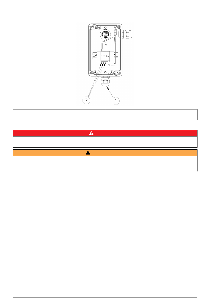
Abbildung 5 Netzanschlussdose
1 Kabeldurchführung für das Netzkabel 2 Anschlussklemmen (1 = Schutz, 2 = Neutral 3 =
stromführend)
Anschlüsse für Eingang/Ausgang
G E F AH R
Gefahr von Stromschlägen. Vor der Erstellung der hier beschriebenen Anschlüsse muss der Analysator
ausgeschaltet und von der Netzversorgung getrennt werden.
Um die Konformität mit den Sicherheitsstandards zu gewährleisten und den EMV-Anforderungen des Analysators
zu entsprechen, verfahren Sie beim Anschluss von Peripheriegeräten an die elektronische Einheit des
Analysators wie folgt:Verkabelung und Kabelvorbereitung auf Seite 33
Die elektronische Einheit (Nr. 11 in Abbildung 1 auf Seite 30) muss für die Erstellung dieser
Anschlüsse auf der Rückseite geöffnet werden. Lösen Sie die vier Befestigungsschrauben der
Geräterückwand und bewegen Sie diese dann vorsichtig von links nach rechts. Für die Position der
Klemmen beziehen Sie sich auf Abbildung 6 und die folgenden Tabellen, in denen die Funktionen
aufgeführt sind.
Hinweis: Eine Kopie des Klemmenschemas befindet sich auch auf der Rückwand der elektronischen Einheit.
W A R NU N G
38
Deutsch
Page 39
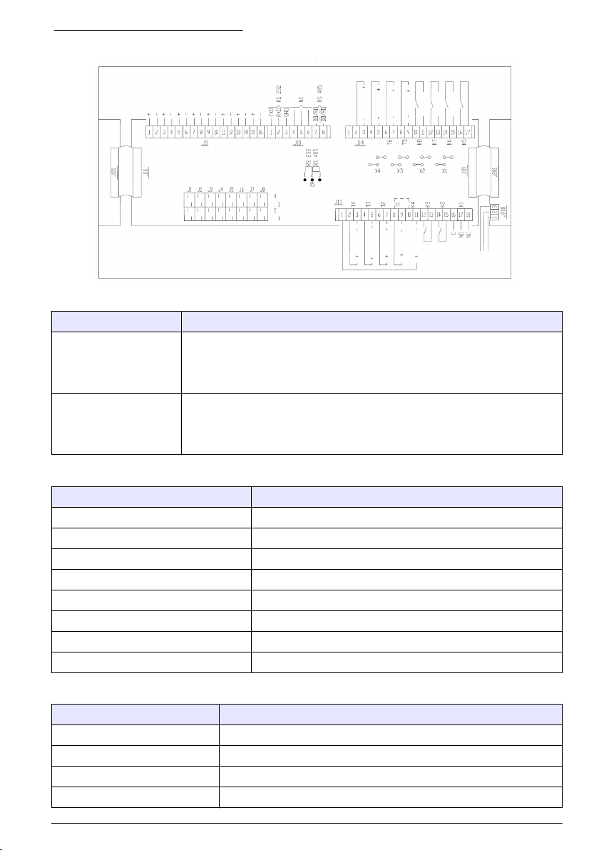
Abbildung 6 Klemmenanschlüsse
Tabelle 1 Mikroprozessorkarte
Klemme Beschreibung
Relaiskonfiguration K5 - K8
X1 - X4
X5
• 2-3: Potentialfreier Kontakt
• 1-2 und 3-4: 24 V DC
Serielle Schnittstelle
• 1-2: RS 232
• 2-3: RS 485
Tabelle 2 Füllstanddektor und externe Befehle (J1 - J8)
Klemme Verwendung
J1 Start/Standby
J2 Externe Probe
J3 Nicht verwendet
J4 Konditionierungslösung
J5 Titrationslösung
J6 Kalibrierungslösung
J7 Chemische Reinigung
J8 Probe
Tabelle 3 Analoge Ausgänge
Klemme Verwendung
1-2 Analoger Ausgang 1
3-4 Analoger Ausgang 2
5-6 Analoger Ausgang 3
7-8 Analoger Ausgang 4
Deutsch 39
Page 40
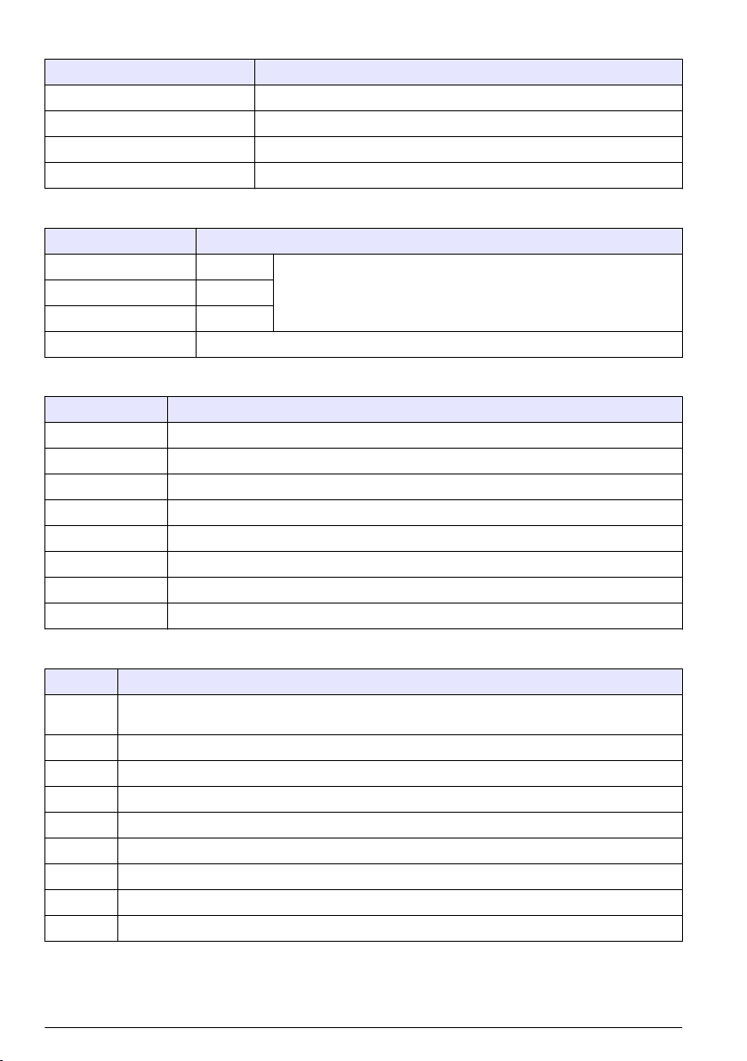
Tabelle 3 Analoge Ausgänge (fortgesetzt)
Klemme Verwendung
9-10 Analoger Ausgang 5
11-12 Analoger Ausgang 6
13-14 Analoger Ausgang 7
15-16 Analoger Ausgang 8
Tabelle 4 Serielle Schnittstelle (J10)
Klemme Verwendung
1 TXD
RS 232 benutzerkonfiguriert mit X5 2 RXD
3 GND
4, 5, 6, 7, 8 Nicht verwendet
Tabelle 5 Zubehör 1 (J13)
Klemme Verwendung
1-11 Heizsystem
2-3 Mixer
4-5 Spülventil
6-7 Druckspüler
8-9 Probenventil
12-13 Alarm 2
14-15 Alarm 1
16-17-18 Systemalarm (16-17 für NO oder 16-18 für NC)
Tabelle 6 Zubehör 2 (J14)
Klemme Verwendung
1-11 (8-10) Automatische Kalibrierung oder externe Probenpumpe (8 und 10 anschließen und Jumper X4 auf
2-3 Nicht verwendet
4-5 Chemische Reinigung
6-7 Verdünnungsventil
8-9 Nicht verwendet
10-11 Pumpe 4
12-13 Pumpe 3 (X3 auf 1-2 und 3-4 gesetzt)
14-15 Pumpe 2 (X2 auf 1-2 und 3-4 setzen)
16-17 Pumpe 1 (X1 auf 1-2 und 3-4 setzen) / Automatische Kalibrierung
2-3 setzen)
40 Deutsch
Page 41
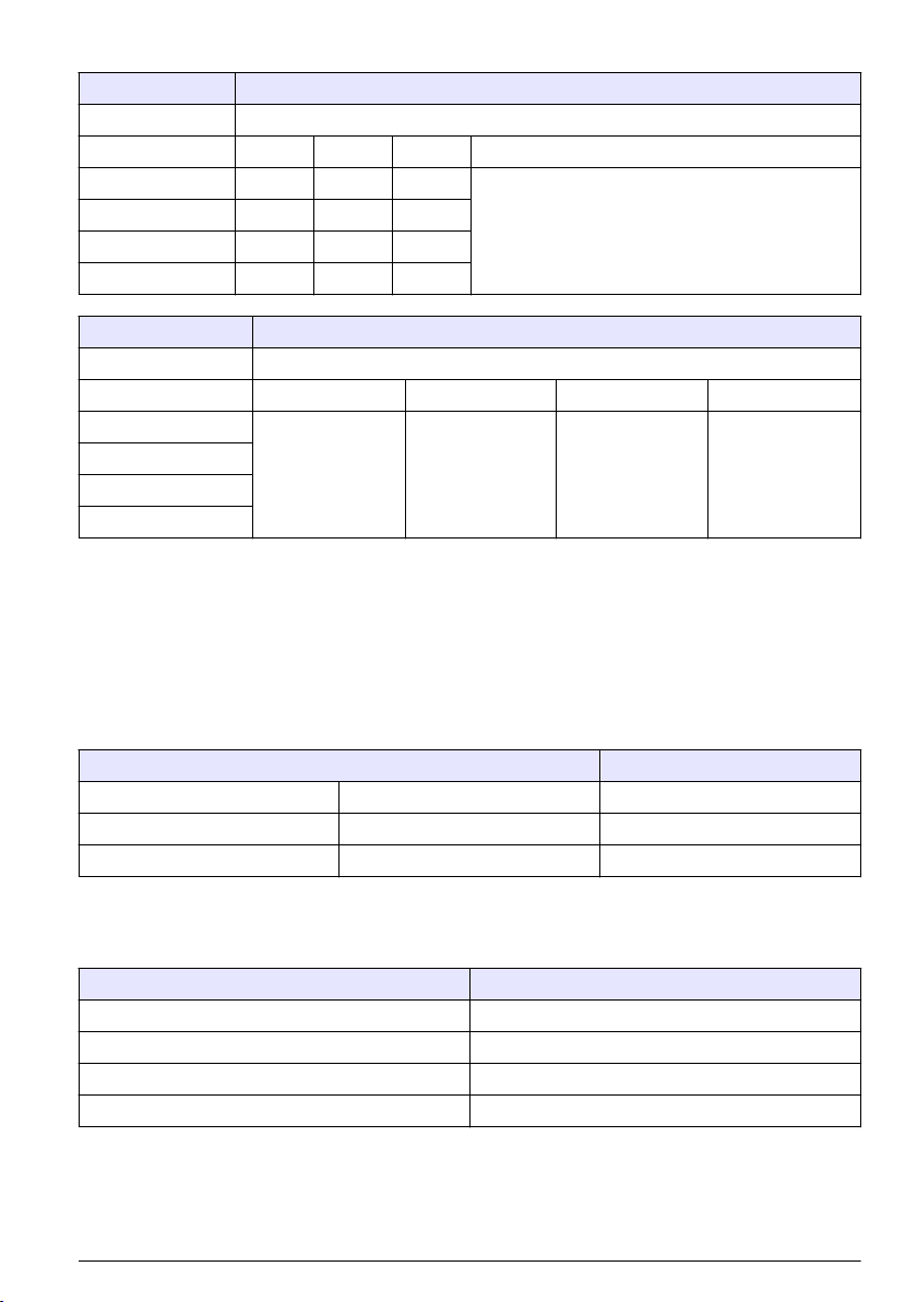
Tabelle 7 Pumpenfunktionen 1 - 4
CAL AUTO YES or MANUAL YES (automat. Kalib. JA oder manuell JA)
Jumper X4 X4 auf 2-3 setzen und zwischen 8 und 10 von J14 einen Streifen setzen
Pumpe 1 Pumpe 2 Pumpe 3 Pumpe 4
1 Titrand Titrand 1 Kond 1
1 Titrand / 2 Kond. Titrand 1 Kond 1 Kond 2
2 Titranden / 1 Kond. Titrand 1 Kond 1 Titrand 2
2 Titranden / 2 Kond. Titrand 1 Kond 1 Titrand 2
CAL AUTO NO and MANUAL NO (automat. Kalib. NEIN und manuell NEIN)
Jumper X4 X4 zwischen 1-2 und 3-4 und Streifen zwischen 8 und 10 von J14 setzen
Pumpe 1 Pumpe 2 Pumpe 3 Pumpe 4
1 Titrand
1 Titrand / 2 Kond.
2 Titranden / 1 Kond.
2 Titranden / 2 Kond.
Titrand 1 Kond 1 Kond 2 Titrand 2
CAL AUTO or OTHER SAMPLE (automat. Kalib. oder
ander Probe)
Alarme
Beziehen Sie sich auch auf Abbildung 6 auf Seite 39 und Tabelle 5 auf Seite 40. Die Relais für die
Alarmschwelle (K2 und K3) sind normalerweise offen (NO). Das Relais für den Systemalarm (K1)
kann als Öffner (Klemmen 16 und 17) oder Schließer (Klemmen 16 und 18) konfiguriert werden.
Analoge Ausgänge
Beziehen Sie sich auch auf Abbildung 6 auf Seite 39 und Tabelle 3 auf Seite 39. Die analogen
Ausgänge 0-20 mA bzw. 4-20 mA sind galvanisch getrennt. In der folgenden Tabelle sind die
Zuweisungen für die einzelnen Ausgänge aufgeführt:
Analysator
I out 1 Klemme 1-2 von J9 Messkanal
I out 2 Klemme 3-4 von J9 Messung Potential
I out 3 Klemme 5-6 von J9 Nicht verwendet
Füllstanddetektor
Beziehen Sie sich auch auf Abbildung 6 auf Seite 39 und Tabelle 2 auf Seite 39. Der Reaktor verfügt
über einen Füllstanddetektor für die Probe. Verkabeln Sie den Anschluss an J8 wie folgt:
Klemmennummer J8 Farbe
1 Braun
2 Grün
3 Gelb
4 Weiß
Füllstanddetektor Reagenzlösung
Beziehen Sie sich auch auf Abbildung 6 auf Seite 39 und Tabelle 2 auf Seite 39. Jeder Kanister für
die Reagenzlösung verfügt über einen Füllstanddetektor. Verkabeln Sie die Anschlüsse für jede
Reagenzlösung mit J4, J5, J6 und J7 wie im Folgenden beschrieben.
Deutsch
41
Page 42
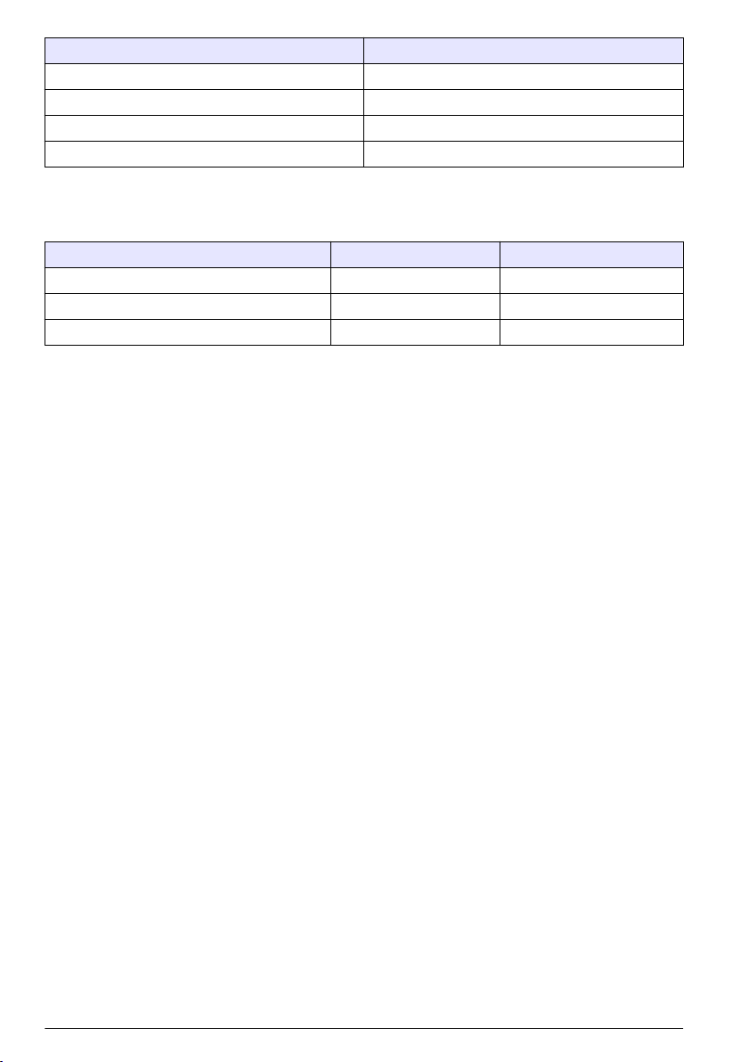
Nummer der Klemmen für J4, J5, J6 und J7 Farbe
1 Nicht verwendet
2 Nicht verwendet
3 Braun
4 Weiß
RS232-Anschluss
Beziehen Sie sich auch auf Abbildung 6 auf Seite 39 und Tabelle 4 auf Seite 40. Verkabeln Sie den
Anschluss an J10 wie folgt:
Klemmennummer J10 DB9-Stecker DB25-Stecker
1 (TXD) RXD: 2 RXD: 2
2 (RXD TXD: 3 TXD: 3
3 (GND) COM: 5 COM: 7
Der 8810 ist wie folgt konfiguriert:
• Geschwindigkeit: 9600 Baud
• Daten: 8 Bits
• Stop-Bit: 2
• Parität: keine
Während der Inbetriebnahme zeigt der Analysator Namen und Versionsnummer der Software an.
• ANALYZER 8810 : 00 : 00 : 00 :
• pH X.XX : 00 : 00 : 00 :
Im Messungsmodus zeigt der Analysator folgende Daten an:
• Titration HH : MM : SS
• M1 XXXXEXX XX.X°C XXX für den ersten Endpunkt
• M2 XXXXEXX XX.X°C XXX für den zweiten Endpunkt
• M3 XXXXEXX XX.X°C XXX Differenz zwischen beiden Endpunkten
Wobei:
• MX XXXXEXX =Wert Konzentrationsmessung
• XX.X°C = Temperatur
• XXX = Wert des Potentials
Während der Kurvenaufzeichnung zeigt der Analysator folgende Daten an:
• Kurvenaufzeichnung HH : MM : SS
• P : XX.X°C XXX
Wobei:
• XX.X°C = Temperatur
• XXX = pH-Wert
Bei folgenden Meldungen zeigt der Analysator außerdem noch Informationen zur Uhrzeit (HH : MM :
SS) an.
42
Deutsch
Page 43
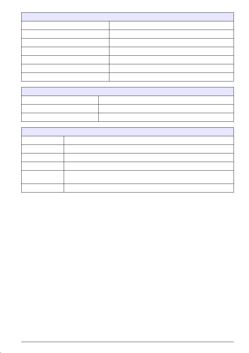
AKTIONEN
Reinigung Chemische Reinigung
Gestoppt Analysator gestoppt
Frist Zeit zwischen zwei Zyklen
Stand-by Analysator im Stand-by-Modus
AUTO SYS CAL Automatische Kalibrierung
PROCESS SYS CAL Prozesskalibrierung
MANUAL SYS CAL Manuelle Kalibrierung
SYSTEM ERRORS
LEVEL SAMPLE Keine Probe von der Messzelle
OVER TITR TIME Titration dauert zu lange
ERROR CALIB Fehler automatische Kalibrierung
WARNUNGEN
LEVEL REAGENT Keine Titration für die Reagenzlösung
LEVEL COND Keine Konditionierungsreagenzlösung
LEVEL CALIB Keine Kalibrierungslösung
LEVEL CLEANING Keine Reinigungslösung
RETURN PROCESS Nach der Messung einer externen Probe zeigt diese Meldung die Wiederaufnahme der
SLOPE CALIB 1/2 Fehler automatische Kalibrierung
Prozessmessung an.
Zubehörteile
Alle Zubehörteile, die gekauft aber werkseitig noch nicht installiert wurden, können jetzt installiert
werden. Anweisungen für die Installation und die Verkabelung finden Sie in der Komplettausgabe
des Benutzerhandbuchs. Nachdem alle Zusatzkomponenten installiert wurden, prüfen Sie bitte
Folgendes für die Messungskammer:
• Nichts hat Kontakt mit dem Rührwerk.
• Der obere Teil der Überlaufleitung befindet sich 2 cm über dem Siphon.
• Der Füllstanddetektor befindet sich 1 cm unter dem Boden der Siphonleitung.
• Wenn die Elektroden noch nicht angeschlossen wurden, schließen Sie die Messelektrode an das
dickere und die Referenzelektrode an das dünnere Kabel an.
Benutzeroberfläche
Beschreibung des vorderen Bedienfelds
Die Bedienerschnittstelle besteht aus einer 4-Tasten-Tastatur, einer numerischen Anzeige und einer
alphanumerischen Anzeige mit 2 x 16 Zeichen.
Deutsch
43
Page 44
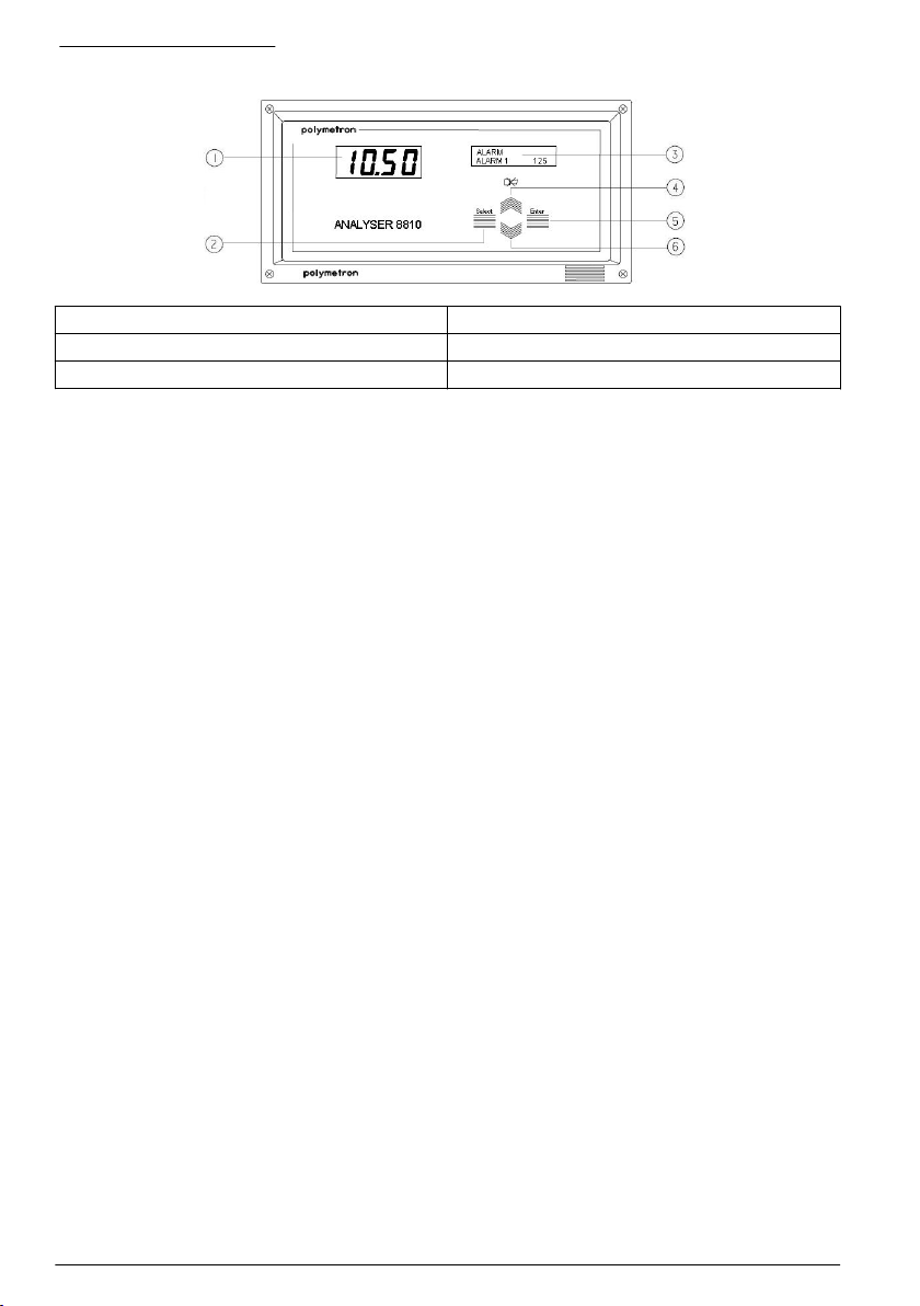
Abbildung 7 Frontpaneel
1 Numerische Anzeige 4 Scroll-up-Taste
2 Auswahltaste 5 Eingabetaste
3 Alphanumerische Anzeige 6 Scroll-down-Taste
Funktionstasten
• Enter: Funktionen aufrufen oder Parameter bestätigen.
• Select: Menüoptionen auswählen, Parameter anpassen, Untermenüs verlassen und vom
Betriebsmodus auf den Befehlsmodus und umgekehrt umschalten.
• Scroll down: Variablen anpassen, im Betriebsmodus das Display und im Befehlsmodus die
Untermenüs abwärtsscrollen.
• Scroll up: Im Betriebs- und Befehlsmenü wie oben aufwärtsscrollen und Systemalarme löschen.
Analysator-Modi
Die Analysator-Funktionen im Betriebs- bzw. Befehlsmodus. Im Betriebsmodus führt der
Analysator Standardfunktionen wie Messungen, Kalibrierungen usw. aus. Außerdem können eine
begrenzte Zahl von Parametern mithilfe der Scroll-Tasten angezeigt werden. Im Befehlsmodus
kann der Analysator programmiert werden. Außerdem können Paramter angezeigt und
Analysatorfunktionen getestet werden. Bei der ersten Inbetriebnahme befindet sich der Analysator
standardmäßig im Befehlsmodus.
Für die Auswahl des Betriebsmodus im Befehlsmodus wählen Sie START im MAIN MENU
(Hauptmenü).
Für die Auswahl des Befehlsmodus im Betriebsmodus drücken Sie die Taste Select (Auswählen),
um den Befehl STOP aufzurufen.
• Für die Anzeige der zuletzt definierten Parameter aus dem STOP-Befehl wählen Sie mit den
Scroll-Tasten READING (Lesen) und drücken anschließend ca. 3 Sekunden die TasteEnter.
• Für die Programmierung des Analysators oder das Testen von Analysatorfunktionen aus dem
STOP-Befehl drücken Sie die die Taste Enter und anschließend erneut Enter, um die Eingabe zu
bestätigen. Verwenden Sie dann die Scroll-Tasten für die Auswahl der Option PROGRAMMING
(Programmieren) und drücken Sie anschließend ca. 3 Sekunden die Taste Enter.
Displays
Numerische Anzeige: Auf diesem Display werden die Konzentration (Standard) sowie die Potential-
und Temperaturmessungen angezeigt.
Alphanumerische Anzeige: Auf diesem Display werden Statusmeldungen und Informationen zur
Programmierung anzeigt. Die Meldungen sind je nach ausgewähltem Modus unterschiedlich:
• Betriebsmodus: Auf der oberen Zeile werden die Einheiten, die Messart und eventuell ausgelöste
Alarme angezeigt. Auf der unteren Zeile wird der Status des Analysators z. B. Kalibrierung,
Titration usw. angezeigt.
• Befehlsmodus: In der oberen Zeile wird das Hauptmenü angezeigt. In der unteren Zeile werden
die Untermenüs und die Dateneinstellungen angezeigt.
44
Deutsch
Page 45

Menüübersicht
MAIN MENU
Im Hauptmenü können Sie auf folgende Funktionen zugreifen.
• STOP - Drücken Sie die Taste Enter, um die Messvorgänge mit sofortiger Wirkung zu stoppen.
• START - Drücken Sie die Taste Enter, um die Messvorgänge mit sofortiger Wirkung zu starten.
• STAND-BY - Drücken Sie Enter, um den Analysator in den Stand-by-Modus zu schalten.
• PROGRAMMING - Analysator programmieren (nur im Befehlsmodus)
• READING - Parameter anzeigen (nur im Betriebs modus)
In den Modi PROGRAMMING und READING können mit den Scroll-Tasten folgenden Optionen
ausgewählt werden:
• MEASUREMENT - Titrationsparameter
• CALIBRATION - Analysator kalibrieren
• ANALOG-OUT - Parameter für die analogen Ausgänge
• ALARM - Parameter für die Alarmgrenzwerte
• SEQUENCE - Messungsmodalität
• SERVICE - Analysator und Zubehör warten
• CLEANING - Parameter für die chemische Reinigung
• SAMPLE COND. - Parameter für die Probenkonditionierung
• CAL PARAMETER - Detailinformationen der Primärkalibrierung und der letzten Kalibrierung
anzeigen
• TIMING - Parameter für den Titrationszyklus
• PM XXXX - Systemkonfiguration (nur im Modus PROGRAMMING und nach Eingabe eines
Passworts verfügbar)
Hinweis: Einige der hier beschriebenen Optionen sind nur dann verfügbar, wenn das entsprechende Zubehör
installiert wurde.
Systemkonfiguration (Option PM XXXX)
Beziehen Sie sich auch für anwendungsspezifische Informationen auf die beiliegende
Dokumentation für das Installationsverfahren.
1. Wählen Sie mit den Scroll-Tasten PM XXXX und drücken Sie anschließend die Taste Enter.
Wechseln Sie mit der Taste Select von einem Eingabefeld zum nächsten, um das erforderliche
Passwort einzugeben. Bestätigen Sie anschließend mit Enter.
Option Beschreibung
APPLICATION Wählen Sie Ihre Anwendung aus der Liste.
UNIT Wählen Sie eine Einheit für die Konzentration aus der Liste. Wenn Sie die Option USER
ADC einstellen Auf diese Funktion dürfen nur Kundendiensttechniker von HACH LANGE zugreifen.
wählen, können Sie Ihre eigene Einheit definieren. Geben Sie dann eine Bezeichnung
(5 Zeichen) ein.
Deutsch 45
Page 46

Option Beschreibung
Iout einstellen Wählen Sie den Ausgangstyp (0-20 mA oder 4-20 mA). Schalten Sie einen Multimeter mit
OPTION Wählen Sie in der Liste YES für die zusätzlichen Optionen, die Sie installiert/angefordert
dem analogen Ausgang in Reihe und korrigieren Sie bei Bedarf das Signal.
haben, und NO für diejenigen, die Sie nicht installiert/angefordert haben.
Hinweis: Für einige Optionen muss zusätzliche Hardware installiert werden z. B. AUTO
SYS CAL, CLEANING, HEATING, etc.). Für den korrekten Betrieb des Analysators muss
die Installation der zusätzlichen Hardware abgeschlossen sein, bevor Sie die Option YES
wählen.
Titrationsparameter (Option MEASUREMENT)
Für SÄURE-BASEN-Anwendungen ist nur ein Parametersatz erforderlich. Für andere Anwendungen
sind zwei Parametersätze erforderlich.
1. Wählen Sie mit den Scroll-Tasten MEASUREMENT und drücken Sie anschließend die Taste
Enter.
Option Beschreibung
PRE-ENDPT1/2 Geben Sie einen Wert für den Punkt vor dem Endpunkt ein.
ENDPT1/2 Geben Sie einen Wert für den Endpunkt ein.
Kalibrierung (Option CALIBRATION)
Kalibrierung im Modus READING (Lesen)
Mit der Option CALIBRATION können die Parameter für die Kalibrierung angezeigt werden. Scrollen
Sie die angezeigte Parameterliste.
Kalibrierung im Modus PROGRAMMING (Programmieren)
Drei Optionen sind verfügbar:
• PRIMARY CALIBRATION
• SYSTEM CALIBRATION
• ELECTRODE CALIBRATION
PRIMARY oder SYSTEM calibration
Eine Primärkalibrierung wurde schon werkseitig ausgeführt. Sie ist die Referenzkalibrierung für alle
weiteren Kalibrierungen. Im Allgemeinen muss diese nur dann erneut werden, wenn wichtige
Systemänderungen vorgenommen wurden, wie z. B. der Austausch der Elektrode.
Der Prozess für die Kalibrierungen PRIMARY oder SYSTEM ist identisch.
1. Wählen Sie im Menü CALIBRATION mit den Scroll-Tasten PRIMARY CAL oder SYSTEM CAL
und drücken Sie anschließend die Taste Enter.
Option Beschreibung
MANUAL SYS CAL Für diese Kalibrierung sind eine odere mehrere im Labor hergestellte
Kalibrierungslösungen mit bekannter Konzentration erforderlich.
46 Deutsch
Page 47

Option Beschreibung
PROCESS SYS CAL Diese Kalibrierung verwendet die Prozesslösung, mit einer bekannten Konzentration,
AUTO SYS CAL Diese Option steht nur dann zur Verfügung, wenn sie installiert wurde.
wie die Kalibrierungslösung.
Manuelle Kalibrierung
1. Wählen Sie MANUAL SYS CAL und drücken Sie anschließend die Taste Enter.
2. Auf dem Display wirdFILL CAL SOL.angezeigt. Gießen Sie die Kalibrierungslösung in die
Messungskammer und drücken Sie Enter.
3. Auf dem Display wird die MeldungCONC SOL: XXXXX angezeigt. Geben Sie die Konzentration
als fünfstellige Zahl ohne Dezimalkomma oder als vierstellige Zahl mit Dezimalkomma ein.
Drücken Sie für die Bestätigung die Taste Enter.
4. Wenn die Option 2 INDEP PTS oder TWO REAGENTS ausgewählt wurde, ist die Konzentration
des 2. Punkts erforderlich. Geben Sie die Konzentration der zweiten Lösung ein und drücken Sie
dann die Taste Enter.
Prozesskalibrierung
1. Wählen Sie PROCESS SYS CAL und drücken Sie anschließend die Taste Enter.
2. Auf dem Display wird die MeldungCONC SOL: XXXXX angezeigt. Geben Sie die Konzentration
als fünfstellige Zahl ohne Dezimalkomma oder als vierstellige Zahl mit Dezimalkomma ein.
Drücken Sie für die Bestätigung die Taste Enter.
3. Wenn die Optionen 2 INDEP PTS oder TWO REAGENTS ausgewählt wurden, ist die
Konzentration des 2. Punkts erforderlich. Geben Sie Konzentration der zweiten Lösung ein und
drücken Sie dann die Taste Enter.
Automatische Kalibrierung
Diese Option steht nur dann zur Verfügung, wenn sie für den Analysator installiert wurde. Sie
ermöglicht die automatische Kalibrierung in voreingestellten Intervallen. Dabei wird eine
Kalibrierungslösung mit einer bekannten Konzentration verwendet.
Hinweis: Wird die Option zum ersten Mal ausgewählt, wählen Sie NO für IMMEDIATE in Punkt 3, damit Sie
erforderlichen zusätzlichen Parameter eingeben können.
1. Prüfen Sie den Inhalt des Kanisters mit der Kalibrierungslösung. Für eine Kalibrierung werden
zwischen 250 und 300 ml Kalibrierungslösung benötigt, so dass mit einer Kanisterfüllung 30 bis
40 Kalibrierungen ausgeführt werden können.
2. Wählen Sie AUTO SYS CAL und drücken Sie anschließend die Taste Enter. Die Meldung
IMMEDIATE wird angezeigt. Wählen Sie YES oder NO und bestätigen Sie anschließend mit
Enter. Wenn Sie YES gewählt haben, wird die Kalibrierung automatisch gestartet. Dann ist keine
weitere Eingabe erforderlich.
3. Wenn Sie NO gewählt haben, geben Sie anschließend einen Wert für FREQUENCY (Frequenz
der Kalibrierung) ein. Dieser Wert entspricht der Anzahl der Titrationen zwischen den
automatischen Kalibrierungen.
4. Auf dem Display wird die MeldungCONC SOL: XXXXX angezeigt. Geben Sie die Konzentration
als eine fünfstellige Zahl ohne Dezimalkomma oder als vierstellige Zahl mit Dezimalkomma ein.
Drücken Sie für die Bestätigung die Taste Enter.
5. Wenn die Optionen 2 INDEP PTS oder TWO REAGENTS ausgewählt wurden, ist die
Konzentration des 2. Punkts erforderlich. Geben Sie die Konzentration der zweiten Lösung ein
und drücken Sie dann die Taste Enter.
6. INJ. Auf dem Display wird die Meldung TIMEangezeigt. Geben Sie die Einspritzungszeit für die
Kalibrierungslösung in Sekunden an und bestätigen dann Sie mit Enter.
Deutsch
47
Page 48

ELEKTRODE kalibrieren
Für die Elektrodenkalibrierung sind zwei Pufferlösungen mit bekannter Konzentration für die
Durchführung einer 2-Punkt-Kalibrierung erforderlich. Die Pufferlösungen sollten unterschiedliche
pH-Konzentrationen zwischen 1 und 9 oder Konzentrationen, die ähnlich wie die der Anwendung
sind, haben. Die Pufferlösung 1 sollte den niedrigeren und die Pufferlösung 2 den höheren pH-Wert
haben.
1. Wählen Sie im Menü CALIBRATION mit den Scroll-Tasten ELECTRODE CAL und drücken Sie
dann die Taste Enter.
Option Beschreibung
2 POINT Drücken Sie die Taste Enter, um die 2-Punkt-Kalibrierung zu bestätigen.
FILL BUFFER 1 Füllen Sie die Messungskammer mit der ersten Pufferlösung und drücken Sie dann die
BUFFER 1: XXXXX Geben Sie den pH-Wert der ersten Pufferlösung ein und drücken Sie dann die Taste
FILL BUFFER 2 Füllen Sie die Messungskammer mit der zweiten Pufferlösung und drücken Sie dann
BUFFER 2: XXXXX Geben Sie den pH-Wert der zweiten Pufferlösung ein und drücken Sie dann die Taste
Taste Enter.
Enter.
die Taste Enter.
Enter.
Resultate der Kalibrierung
Bei Auswahl der Option PRIMARY CAL(Primärkalibrierung) wird die Kalibrierung immer als korrekt
eingestuft und als Referenz für die nachfolgenden Kalibrierungen verwendet. Die Steilheit wird als
100% eingestuft.
Für die nachfolgenden Kalibrierungen werden die neuen Werte für die Steilheit mit den Werten der
Primärkalibrierung verglichen. Liegen die neuen Werte für die Steilheit zwischen 70-130% der
aktuellen Werte, sind sie gültig und werden für die Berechnung der nachfolgenden Kalibrierungen
verwendet.
Liegen die neuen Werte zwischen 50-70% oder 130-150% der aktuellen Werte, müssen sie mit der
Taste CONFIRM als die neuen Werte bestätigt werden. Wählen Sie YES oder NO und bestätigen
Sie anschließend mit Enter. Bei Auswahl der Option YES werden die neuen Parameter für alle
zukünftigen Messungen übernommen. Bei Auswahl der Option NO (oder wenn die neuen Werte für
die Steilheit <50% oder >150% im Verhältnis zu den aktuellen Werten sind) wird die Meldung
ERROR CALIB (Kalibrierungsfehler) angezeigt. Drücken Sie die Taste Enter, um fortzufahren.
Die Meldung CAL ERROR zeigt an, dass bei der Kalibrierung ein Fehler aufgetreten ist. Drücken Sie
die Taste RETRY, um die Kalibrierung zu wiederholen oder wählen Sie ABORT, um die Kalibrierung
abzubrechen.
Bei der automatischen Kalibrierung ist keine Bestätigung erforderlich. Ist die Abweichung für die
Steilheit <50% oder >150% im Verhältnis zu den aktuellen Werten, wird auf jeden Fall die Warnung
SLOPE CALIB ! auf dem Bildschirm angezeigt.
Analoge Ausgänge (Option ANALOG-OUT)
Der Analysator verfügt über zwei analoge Ausgänge, die in Abhängigkeit von der Anwendung
zugewiesen werden.
Anwendung Analoger Ausgang 1 Analoger Ausgang 2
ACID Konzentration der Säure pH beim Start der Titration
BASE Konzentration der Basen pH beim Start der Titration
FREE/TOTAL ACID (freie
Säure/Gesamtsäure)
FREE/TOTAL BASE (freie
Basen/Gesamtbasen)
48 Deutsch
FREE TOTAL
FREE TOTAL
Page 49
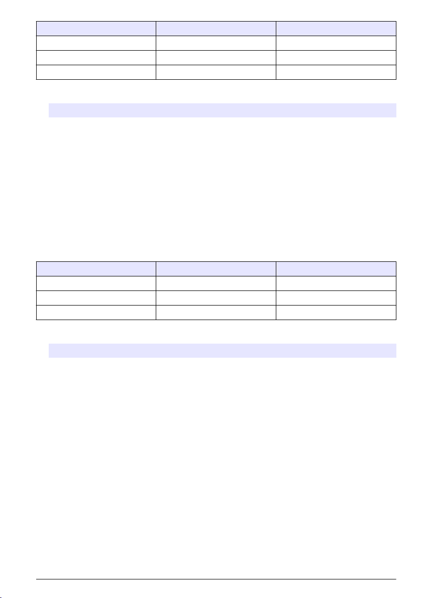
Anwendung Analoger Ausgang 1 Analoger Ausgang 2
2p-m p 2p-m
x(p-m) m x(p-m)
x(m-p) p x(m-p)
1. Wählen Sie mit den Scroll-Tasten ANALOG-OUT und drücken Sie anschließend die Taste Enter.
Option Beschreibung
START I1/2 Geben Sie den Wert ein, der dem Ausgang mit 0-4 mA Stromstärke entspricht.
END I1/2 Geben Sie den Wert ein, der dem Ausgang mit 20 mA Stromstärke entspricht.
Conc Prüfen Sie den Ausgang. Übermitteln Sie dazu eine Stromstärke, die dem zuletzt gemessenen
Full Prüfen Sie den Ausgang. Übermitteln Sie dazu den höchsten Wert für die Stromstärke (20 mA).
Null Prüfen Sie den Ausgang. Übermitteln Sie dazu den niedrigsten Wert für die Stromstärke (0 oder
Hinweis: Sie können dieses Menü nur dann verlassen, wenn Conc angezeigt wird.
Wert entspricht.
4 mA), der für den Analysator eingestellt wurde.
Stellen Sie die Alarme und Alarmschwellen (Option ALARM) ein.
Der Analysator hat drei Alarme, die wie in der Definition für WARNING/R1 zugewiesen wurden:
WARNING/R1 steht auf NO WARNING/R1 steht auf YES
Systemalarm System- und Warnalarm Nur Systemalarm
Alarm 1 Alarm 1 Warnalarm
Alarm 2 Alarm 2 Alarm 1 und 2
1. Wählen Sie mit der Scroll-Taste ALARM und drücken Sie anschließend Enter.
Option Beschreibung
SYS.ALARM ON/OFF Aktiviert oder deaktiviert den Systemalarm.
WARNING/R1 YES/NO Alarmzuweisung (siehe Tabelle oben) definieren.
ALARM 1/2 ON/OFF Alarme 1 und 2 aktivieren oder deaktivieren.
ALARM 1/2 XXX/XXX Bei aktiviertem Alarm die Messung definieren, die den Alarm auslösen soll
(anwendungsspezifisch).
Deutsch 49
Page 50

Option Beschreibung
ALARM 1/2 HIGH/LOW Bei aktiviertem Alarm definieren, ob der Auslöser ein hoher oder ein niedriger
ALARM 1/2 XXX Schwellenwert eingeben. Wurde für den Alarm die Einstellung HIGH (hoher
Messwert sein soll.
Messerwert) gewählt, wird durch jeden Messwert, der über dem eingestellten Wert
liegt, ein Alarm ausgelöst. Umgekehrt wird bei der Einstellung LOW (niedriger
Messwert) bei jedem Wert, der unter dem eingestellten Wert liegt, ein Alarm
ausgelöst.
Messungsmodus (Option SEQUENCE)
Wählen Sie den Messungsmodus aus.
1. Wählen Sie mit den Scroll-Tasten SEQUENCE und drücken Sie anschließend die Taste Enter.
Wählen Sie den gewünschten Modus mit den Scroll-Tasten aus.
Option Beschreibung
FIX TIME Fester Zeitintervall zwischen den Messungen. Der Intervall wird in Parameter für die Messzyklen
LOOP Kontinuierliche Messung. Dann ist keine weitere Eingabe erforderlich.
PLOT pH Wählen Sie diese Funktion, wenn eine Titrationskurve erstellt werden soll. Geben Sie die Werte
(Option TIMING) auf Seite 51 definiert.
für START pH und END pH (zwischen 0 und 14) ein. Sie bestimmen die Ausgänge für 0-4 mA
und 20 mA. Wurde die Option TWO REAGENTS ausgewählt, müssen Sie eingeben, welche
Reagenzlösung verwendet wird, um die Steilheit zu definieren.
Analysator und Zubehör testen (Option SERVICE)
Prüfen Sie, ob die einzelnen Zubehörgeräte (z. B. Pumpe) korrekt arbeiten. In dieser Liste haben Sie
auch Zugriff auf die Funktion für die Anzeige der Versionsnummer der Software.
1. Wählen Sie mit den Scroll-Tasten SERVICE und drücken Sie anschließend die Taste Enter.
2. Stellen Sie für die Funktion, die getestet werden soll, die Option ON ein, um diese zu starten.
Nachdem das Zubehörgerät getestet wurde, stellen Sie Funktion wieder auf OFF, um diese
auszuschalten.
Chemische Reinigung (Option CLEANING)
Diese Option wird nur dann angezeigt, wenn die Option CLEANING (Reinigen) aktiviert wurde.
Definieren Sie die erforderlichen Parameter für die chemische Reinigung des Systems.
1. Wählen Sie mit den Scroll-Tasten die Option CLEANING (Reinigen). Drücken Sie anschließend
die Taste Enter.
Option Beschreibung
FREQUENCY Geben Sie an, wie viele Messungen zwischen den chemischen Reinigungen durchgeführt
SPRINKLER Legen Sie fest, wie lange (in Sekunden) die Messungskammer gespült werden soll.
REAG. INJ Legen Sie fest, wie lange (in Sekunden) die Reinigungslösung in die Messungskammer
RESIDENC. Legen Sie fest, wie lange (in Sekunden) die Reinigungslösung in der Messungskammer
werden können.
gespritzt werden soll.
bleiben soll.
Probenkonditionierung (Option SAMPLE COND)
Diese Option wird angezeigt, wenn die Option SAMPLE COND aktiviert wurde.
50
Deutsch
Page 51

Geben Sie die erforderlichen Parameter für die Konditionierung der Probe vor der Messung ein. Sie
können 1 oder 2 Reagenzlösungen für die Konditionierung eingeben.
1. Wählen Sie mit den Scroll-Tasten SAMPLE COND und drücken Sie anschließend die Taste
Enter.
Option Beschreibung
REAGENT 1/2 OFF/ON Wählen Sie ON, wenn die Konditionierung mit dieser Reagenzlösung durchgeführt
INJ. REAG. 1/2 Geben Sie an , wie lange (in Sekunden) die Reagenzlösung in die
TIME REAG. 1/2 Geben Sie an, wie lange (in Sekunden) die Reagenzlösung vor der Messung in der
wird.
Messungskammer eingespritzt werden soll.
Probe bleiben soll.
Kalibrierungsdetails anzeigen (Option CAL PARAMETER)
Mit dieser Funktion können Sie die Details der Primärkalibrierung und der letzten Kalibrierung, die
von dem Analysator durchgeführt wurde, aufrufen.
1. Wählen Sie mit den Scroll-Tasten die Option CAL PARAMETER (Kalibrierungsparameter) und
drücken Sie anschließend die Taste Enter.
2. Wählen Sie mit den Scroll-Tasten LAST CAL (letzte Kalibrierung) bzw. PRIMARY CAL
(Primärkalibrierung), drücken Sie anschließend Enter, um die Details zu scrollen.
Parameter für die Messzyklen (Option TIMING)
Geben Sie die Parameter für jeden Messzyklus ein.
1. Wählen Sie mit den Scroll-Tasten TIMING und drücken Sie anschließend die Taste Enter.
Option Beschreibung
SAMPLE TIME Geben Sie an, wie lange (in Sekunden) die Probe in die Messkammer eingespritzt werden
SPRINKLER N Geben Sie an, wie viele Spülungen erforderlich sind.
SPRINKLER t Geben Sie an, wie lange (in Sekunden) jede Spülung dauern soll.
INJECT TIME Geben an, wie lange (in Sekunden) die Reagenzlösung in die Messkammer eingespritzt
DELAY TIME Geben Sie an, wie viel Zeit (in Sekunden) zwischen einer Einspritzung und der nächsten
ZYKLUSZEIT Geben Sie an, wie lange (in Minuten) der Messungszyklus dauern soll.
LIM. TIT. t Geben Sie an, wie lange (in Minuten) die Titration maximal dauern soll. Bei Überschreiten
soll.
werden soll.
liegen soll.
dieser Zeit wird ein Alarm ausgelöst.
Wartung
G E F AH R
Gefahr von Stromschlägen. Vor allen Wartungsarbeiten muss der Analysator ausgeschaltet und von der
Netzversorgung getrennt werden.
Allgemeines
Für die periodische Routinewartungen kann bequem auf alle Elemente auf dem Frontpaneel
zugegriffen werden.
Deutsch
51
Page 52

Für die Installation von Zubehör und spezielle Wartungsarbeiten kann mit einfachen Handgriffen von
allen Seiten auf den Analysator zugegriffen werden. Für den Zugriff und die eventuelle Entnahme der
elektronischen Steuereinheit und der Analyseeinheiten muss das Frontpaneel mit einem speziellen
Schraubenschlüssel (Lieferumfang) abgenommen werden.
Wartungsintervalle
Der Wartungsplan hängt von der Anwendungsart ab. Generell sollten folgende Wartungsschritte
monatlich durchgeführt werden:
• Prüfen Sie alle Reagenzlösungs- und Chemikalienbehälter. Füllen Sie die Behälter bei Bedarf auf.
• Lösen Sie die Schlauchleitungen und montieren Sie diese umgekehrt.
• Tauschen Sie die Schlauchleitungen alle 2 Monate aus.
• Prüfen Sie, ob sich in der Messungskammer und auf den Elektroden Ablagerungen gebildet
haben. Entfernen Sie eventuell sichtbare Verschmutzungen.
• Prüfen Sie die Dichtheit alle Anschlüsse.
• Prüfen Sie, ob die Anlage ruhig läuft. Führen Sie bei Bedarf eine Kalibrierung durch.
Reinigung und Dekontamination
Normalerweise muss der Analysator nicht gereinigt oder dekontaminiert werden.
Bei Bedarf das Instrument außen mit einem feuchten Tuch und einer sanften Seifenlösung reinigen.
Niemals Reinigungsmittel wie Terpentinöl, Azeton oder ähnliche Produkte für die Reinigung des
Instruments, des Displays oder anderer Zubehörteile verwenden.
Außerbetriebnahme
Messzyklus ausschalten
Wählen Sie im Hauptmenü STOP und drücken Sie anschließend die Taste Enter. Auf dem Display
erscheint die Meldung stopped.
Kurzfristige Außerbetriebnahme (z. B. Wochenende)
Wählen Sie im Hauptmenü STAND BY und drücken Sie anschließend die Taste Enter, um das
System in den Stand-by-Modus zu schalten. Die Messungskammer wird entleert, gespült und mit
Spülwasser gefüllt.
Langfristige Außerbetriebnahme
Wenn das System für einen längeren Zeitraum außer Betrieb genommen wird, müssen die
Elektroden gereinigt und die Messungskammern gespült werden. Außerdem empfiehlt es sich, die
Elektroden zu entfernen und bis zur erneuten Inbetriebnahme des Geräts in einer Pufferlösung zu
lagern. Die Elektroden dürfen auf keinen Fall in der leeren Messungskammer gelagert werden. Sie
trocknen dann aus und werden dadurch beschädigt. Schließlich schalten Sie das Gerät aus.
52
Deutsch
Page 53
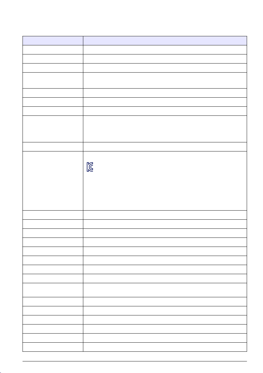
Specifiche
Le specifiche sono soggette a modifica senza preavviso.
Specifiche Dettagli
Temperatura ambiente 5 - 40°C (41 - 104°F)
Umidità relativa Da 10 a 80%
Altitudine di esercizio Da 0 a 2.000 m. (6.550 piedi) sopra il livello del mare
Alimentazione elettrica 110/220/240 VAC, 50/60 Hz, ± 10%
Fusibili: 110-120 V, T630mAL250V; 220V-240 V, T1.25AL250V
Consumo max. 110 VA
Categoria di sovratensione 2 (in base alla normativa EN 61010-1)
Grado di inquinamento 2
Compatibilità CE EN61326-1: Direttiva EMC
Nota: Questo è un prodotto di Classe A. In un ambiente domestico questo prodotto può
causare interferenze radio per cui l’utente è tenuto a adottare adeguate misure preventive.
EN61010-1: Direttiva sulla bassa tensione
Certificazione ETL ETL, conforme a UL 61010-1 e CSA 22.2 Nr. 61010-1
Certificazione coreana
Aria compressa 4 - 7 bar, filtrata e asciutta
Pressione acqua di lavaggio 0,5 - 6 bar
Reagenti Contenitore da 10 litri (in dotazione)
Uscite analogiche Numero: 2; 0 - 20 o 4 - 20 lineari programmabili
Allarmi 2 relè (concentrazione); 1 avvertimento o allarme sistema
Sensori scambiabili Elettrodo pH + riferimento
Compensazione temperatura Pt100
Controllo livello Campione; Reagenti; Soluzione di calibrazione; Pulizia chimica
Pompe Peristaltica, micro pistone, a impulsi o volumetrica per i reagenti di
Tubo Tygon®; Polietilene
Consumo di reagente Specifico dell'applicazione
Durata titolazione Specifica dell'applicazione
Durata ciclo Programmabile fino a 999 minuti
Accuratezza < da ± 2 a 4% (specifica dell'applicazione)
Riproducibilità < da ± 2 a 4% (specifica dell'applicazione)
User Guidance for EMC Class A Equipment
업무용을 위한 EMC 등급 A 장치에 대한
사용자 지침
사용자안내문
A 급 기기 ( 업무용 방송통신기자재 )
이 기기는 업무용 (A 급 ) 전자파적합기기로서 판매자 또는 사용자는 이 점을 주의
하시기 바라며 , 가정외의 지역에서 사용하는 것을 목적으로 합니다.
condizionamento e calibrazione
Italiano 53
Page 54
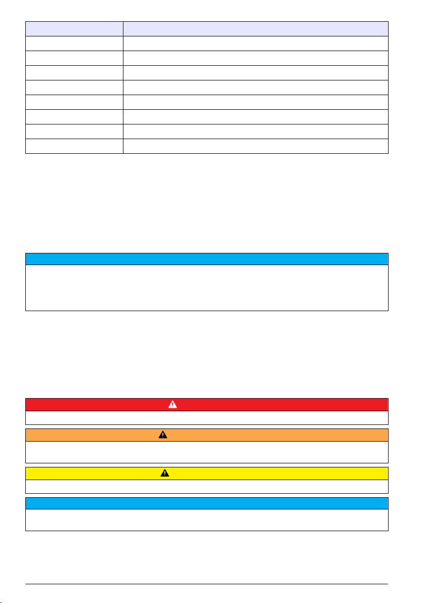
Specifiche Dettagli
Linee campione 1
Temperatura campione 0 - 50°C (32 - 122°F)
Pressione del campione 0,5 - 6 bar
Portata campione 40 - 300 litri/ora
Volume/ciclo campione 200 - 1000 mL (regolabile)
Montaggio su pannello 743 x 482 x 122 mm (A x L x P); < 20 kg
Armadio (IP 54) 1900 x 600 x 400 mm (A x L x P); < 100 kg
Livello massimo di rumore ≤ 80 dBA
Informazioni generali
In nessun caso, il produttore potrà essere ritenuto responsabile per danni diretti, indiretti o accidentali
per qualsiasi difetto o omissione relativa al presente manuale. Il produttore si riserva il diritto di
apportare eventuali modifiche al presente manuale e ai prodotti ivi descritti in qualsiasi momento
senza alcuna notifica o obbligo preventivi. Le edizioni riviste sono presenti nel sito Web del
produttore.
Informazioni sulla sicurezza
A V V IS O
Il produttore non sarà da ritenersi responsabile in caso di danni causati dall'applicazione errata o dall'uso errato di
questo prodotto inclusi, a puro titolo esemplificativo e non limitativo, i danni incidentali e consequenziali; inoltre
declina qualsiasi responsabilità per tali danni entro i limiti previsti dalle leggi vigenti. La responsabilità relativa
all'identificazione dei rischi critici dell'applicazione e all'installazione di meccanismi appropriati per proteggere le
attività in caso di eventuale malfunzionamento dell'apparecchiatura compete unicamente all'utilizzatore.
Prima di disimballare, installare o utilizzare l’apparecchio, si prega di leggere l’intero manuale. Si
raccomanda di leggere con attenzione e rispettare le istruzioni riguardanti note di pericolosità. La non
osservanza di tali indicazioni potrebbe comportare lesioni gravi all'operatore o danni all'apparecchio.
Assicurarsi che i dispositivi di sicurezza insiti nell'apparecchio siano efficaci all'atto della messa in
servizio e durante l'utilizzo dello stesso. Non utilizzare o installare questa apparecchiatura in modo
diverso da quanto specificato nel presente manuale.
Indicazioni e significato dei segnali di pericolo
P E R IC O L O
Indica una situazione di pericolo potenziale o imminente che, se non evitata, causa lesioni gravi anche mortali.
A V V ER T E N Z A
Indica una situazione di pericolo potenziale o imminente che, se non evitata, potrebbe comportare lesioni gravi,
anche mortali.
A T T EN ZI O N E
Indica una situazione di pericolo potenziale che potrebbe comportare lesioni lievi o moderate.
Indica una situazione che, se non evitata, può danneggiare lo strumento. Informazioni che richiedono particolare
attenzione da parte dell'utente.
54 Italiano
A V V IS O
Page 55
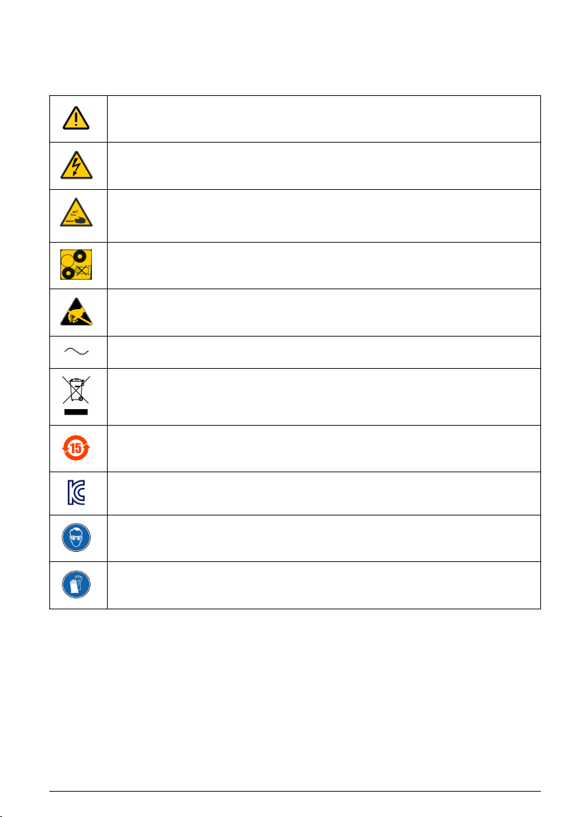
Etichette precauzionali
Leggere tutte le etichette e le targhette applicate sul prodotto. La mancata osservanza delle
precauzioni segnalate potrebbe causare lesioni personali o danni al prodotto. A ogni simbolo
riportato sullo strumento corrisponde un'indicazione di pericolo o di avvertenza nel manuale.
Questo simbolo, se presente sul prodotto, indica un potenziale pericolo che potrebbe causare gravi
lesioni personali e/o morte. Per le istruzioni sul funzionamento dello strumento e/o le informazioni
inerenti alla sicurezza, l'utente deve attenersi a quanto riportato nel presente manuale.
Questo simbolo, se presente sulla custodia o la barriera protettiva del prodotto, indica l'esistenza di
un rischio di elettrocuzione e solo il personale qualificato ad operare con tensioni pericolose è
autorizzato ad aprire la custodia o rimuovere la barriera.
Questo simbolo identifica la presenza di una forte sostanza corrosiva o altra sostanza pericolosa e
un rischio di danno chimico. Solo individui qualificati e addestrati a lavorare con sostanze chimiche
devono maneggiare sostanze chimiche o eseguire la manutenzione di sistemi di erogazione di
sostanze chimiche associati all'apparecchiatura.
Questo simbolo, applicato sui prodotti, segnala un pericolo di schiacciamento delle dita.
Questo simbolo, se presente sul prodotto, indica la presenza di dispositivi sensibili alle scariche
elettrostatiche e segnala la necessità di agire con attenzione per evitare di danneggiarli.
Questo simbolo, quando applicato su un prodotto, indica che lo strumento è collegato a corrente
alternata.
Le apparecchiature elettriche contrassegnate con questo simbolo non possono essere smaltite
presso i centri di smaltimento pubblici o domestici europei. Le apparecchiature obsolete o giunte al
termine della loro vita utile devono essere restituite al produttore per lo smaltimento, senza alcun
addebito all'utente.
I prodotti contrassegnati dal presente simbolo contengono sostanze o elementi tossici o pericolosi.
Il numero all'interno del simbolo indica il periodo di utilizzo senza rischio per l'ambiente, espresso in
anni.
I prodotti contrassegnati con questo simbolo sono conformi alla direttiva EMC per la Corea del Sud.
Questo simbolo, se presente sul prodotto, indica la necessità di indossare occhiali protettivi.
Questo simbolo indica la necessità di indossare guanti protettivi
Panoramica dell'analizzatore
L'analizzatore di elettrodi iono-selettivi (ISE) POLYMETRON modello 8810 è un sistema modulare
utilizzato per le misurazioni ISE in un'ampia gamma di applicazioni industriali in linea. L'analizzatore
acquisisce automaticamente i campioni in linea, aggiunge gli agenti chimici necessari, come
reagenti, tamponi e agenti mascheranti, e completa l'analisi. L'analizzatore è adatto per l'uso in
ambienti in linea industriali in condizioni gravose.
La versione standard prevede il montaggio a pannello, ma sono anche disponibili un armadietto in
poliestere da montare a parete e un armadietto da pavimento, con vano inferiore per i reagenti
necessari per l'analizzatore. I bidoni dei reagenti vengono installati sotto l'unità di controllo elettronico
per offrire protezione e semplicità di accesso e permettere lo svolgimento di attività di manutenzione.
Italiano
55
Page 56
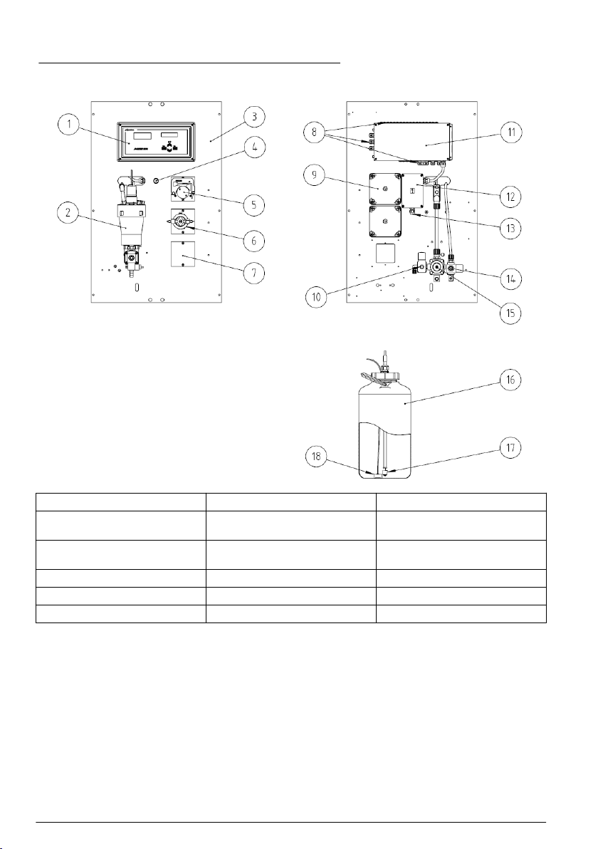
Il pannello incernierato si inclina in avanti per consentire l'accesso alla parte posteriore. Vedere la
Figura 1 per una panoramica del prodotto.
Figura 1 Vista frontale e posteriore (versione pannello)
1 Unità elettronica 7 Spazio per pompa aggiuntiva 13 Collegamento alimentazione
2 Cella di misura (vedere Figura 2
a pagina 57)
3 Pannello da 19 pollici 9 Coperchio della pompa del
4 Interruttore principale 10 Valvola dell'aria compressa 16 Contenitore del reagente
5 Pompa peristaltica 11 Unità elettronica (retro) 17 Rilevatore del livello
6 Micro pompa a pistone 12 Scatola di alimentazione 18 Peso del tubo
8 Collegamento degli ingressi e
delle uscite
reagente
14 Valvola di lavaggio
15 Valvola di campione
Cella di misura
Vedere la Figura 2 per i componenti della cella di misura.
56
Italiano
Page 57
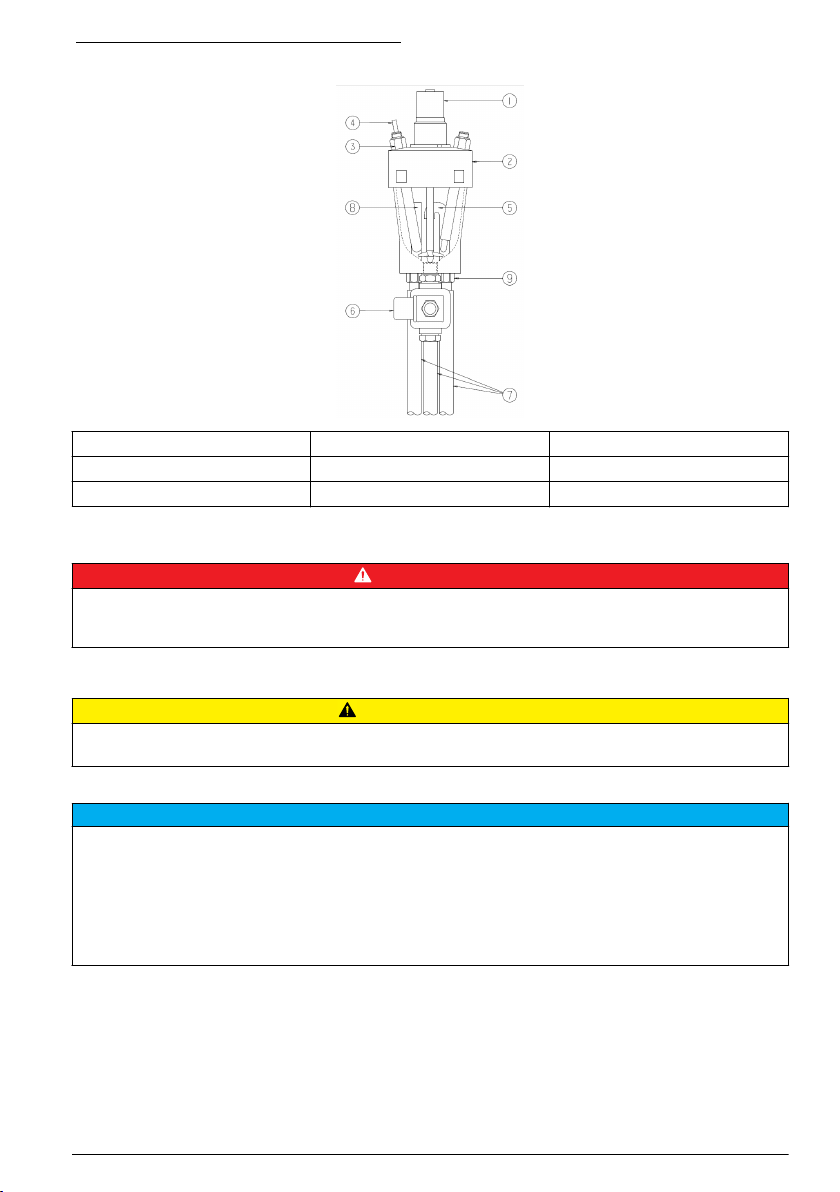
Figura 2 Componenti della cella di misura
1 Motore agitatore 4 Cavo dell'elettrodo 7 Tubo di scarico
2 Copertura cella di misura 5 Sifone 8 Tubo di tracimazione
3 Elettrodo 6 Valvola di scarico 9 Raccordi filettati
Installazione
P E R IC O L O
Rischi multipli. Gli interventi descritti in questa sezione del documento devono essere eseguiti solo da personale
qualificato. Il collegamento alla rete elettrica deve avvenire solo al termine dell'installazione, dopo avere eseguito
gli opportuni controlli.
Installazione dei componenti meccanici
A T T EN ZI O N E
Rischi multipli. Gli interventi descritti in questa sezione del documento devono essere eseguiti solo da personale
qualificato.
Installazione dell'analizzatore
L'analizzatore deve essere montato il più vicino possibile all'ingresso del campione ed essere collocato in un'area
facilmente accessibile per agevolare il controllo periodico della velocità di flusso del campione e i normali
interventi di manutenzione. In una posizione che fornisca protezione dalla luce solare diretta e dalle precipitazioni,
buona ventilazione e controllo della temperatura se installato all'esterno. Indipendentemente dal luogo
d'installazione, l'analizzatore deve essere posizionato verticalmente, tenendo l'unità elettronica ( N. 1 nella
Figura 1 a pagina 56) in alto. Si raccomanda l'impiego di una livella a bolla d'aria per assicurarsi che l'analizzatore
sia correttamente posizionato e non penda lateralmente o in avanti. Solo in questo modo si potrà garantire
l'accuratezza dell'analizzatore.
Montaggio su pannello
Questo modello è nato per l'installazione su scaffale da 48,26 cm. La confezione include sei viti
M6 per l'installazione del pannello su uno scaffale. Tutti i collegamenti interni sono predisposti in
fabbrica. I contenitori dei reagenti possono essere collocati su un vassoio opzionale.
A V V IS O
Italiano
57
Page 58
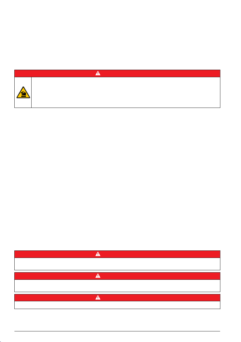
Montaggio a parete
Tutti i collegamenti interni sono predisposti in fabbrica. I cavi e i tubi vengono fatti scorrere attraverso
i pressacavi collocati sul lato inferiore destro dell'armadio. I contenitori dei reagenti possono essere
collocati su un vassoio opzionale.
Per aprire l'armadio, spingere la maniglia verso l'alto, premere il pulsante di blocco quindi aprire lo
sportello ruotando la maniglia di 45 gradi a sinistra. Per accedere all'interno dell'armadio, rimuovere
le vite zigrinata sul lato destro del pannello e spostare delicatamente il pannello verso sinistra
facendo attenzione a non schiacciare i tubi.
Collegamenti idraulici
P E R IC O L O
Rischi chimici o biologici. Se questo strumento viene utilizzato per monitorare un processo di
trattamento e/o un sistema di alimentazione di sostanze chimiche per cui esistono limiti normativi e
requisiti di controllo legati a sanità pubblica, sicurezza pubblica, attività di produzione o trasformazione
di alimenti e bevande, l'utente dello strumento ha la responsabilità di conoscere e rispettare tutte le
eventuali normative applicabili e di predisporre meccanismi adeguati e sufficienti ai fini del rispetto delle
normative vigenti in caso di malfunzionamento dello strumento stesso.
Campione
Il campione entra nell'analizzatore attraverso un tubo flessibile da 12/14 mm (N. 15 nella Figura 1
a pagina 56). La velocità del flusso deve essere compresa tra 40 e 300 litri/ora a una pressione di
0,5 - 6 bar.
Acqua di lavaggio
L'acqua per il lavaggio entra nell'analizzatore attraverso un tubo flessibile da 6/8 mm (N. 14 nella
Figura 1 a pagina 56). La pressione dell'acqua deve essere compresa tra 1 e 6 bar.
Reagenti
I contenitori del reagente vengono collegati alle pompe attenendosi alle istruzioni fornite per
l'applicazione in uso.
Scarico
Il campione analizzato viene scaricato a pressione atmosferica attraverso un tubo flessibile da
12 mm (N. 7 nella Figura 2 a pagina 57) fornito insieme all'analizzatore per l'avvio iniziale.
Controllare che non si verifichi alcun reflusso in questo tubo o negli altri due tubi di scarico
(tracimazione N. 8 nella Figura 2 a pagina 57 e sifone N. 5 nella Figura 2 a pagina 57).
Nota: Per il modello ad armadio, questi tre tubi scaricano in un contenitore con uno sbocco di 50 mm.
Connessione aria compressa
L'analizzatore richiede l'uso di aria compressa, secca e filtrata, con una pressione compresa tra 4 e
7 bar. L'aria deve essere fornita alla valvola (N. 10 nella Figura 1 a pagina 56) utilizzando un
apposito tubo in plastica di diametro 4/6 mm.
Installazione elettrica
P E R IC O L O
Rischi multipli. Gli interventi descritti in questa sezione del documento devono essere eseguiti solo da personale
qualificato.
Pericolo di folgorazione. Verificare sempre che l'analizzatore sia spento e che il cavo di alimentazione sia
scollegato prima di effettuare delle connessioni elettriche.
Pericolo di folgorazione. È necessario predisporre la messa a terra.
58 Italiano
P E R IC O L O
P E R IC O L O
Page 59
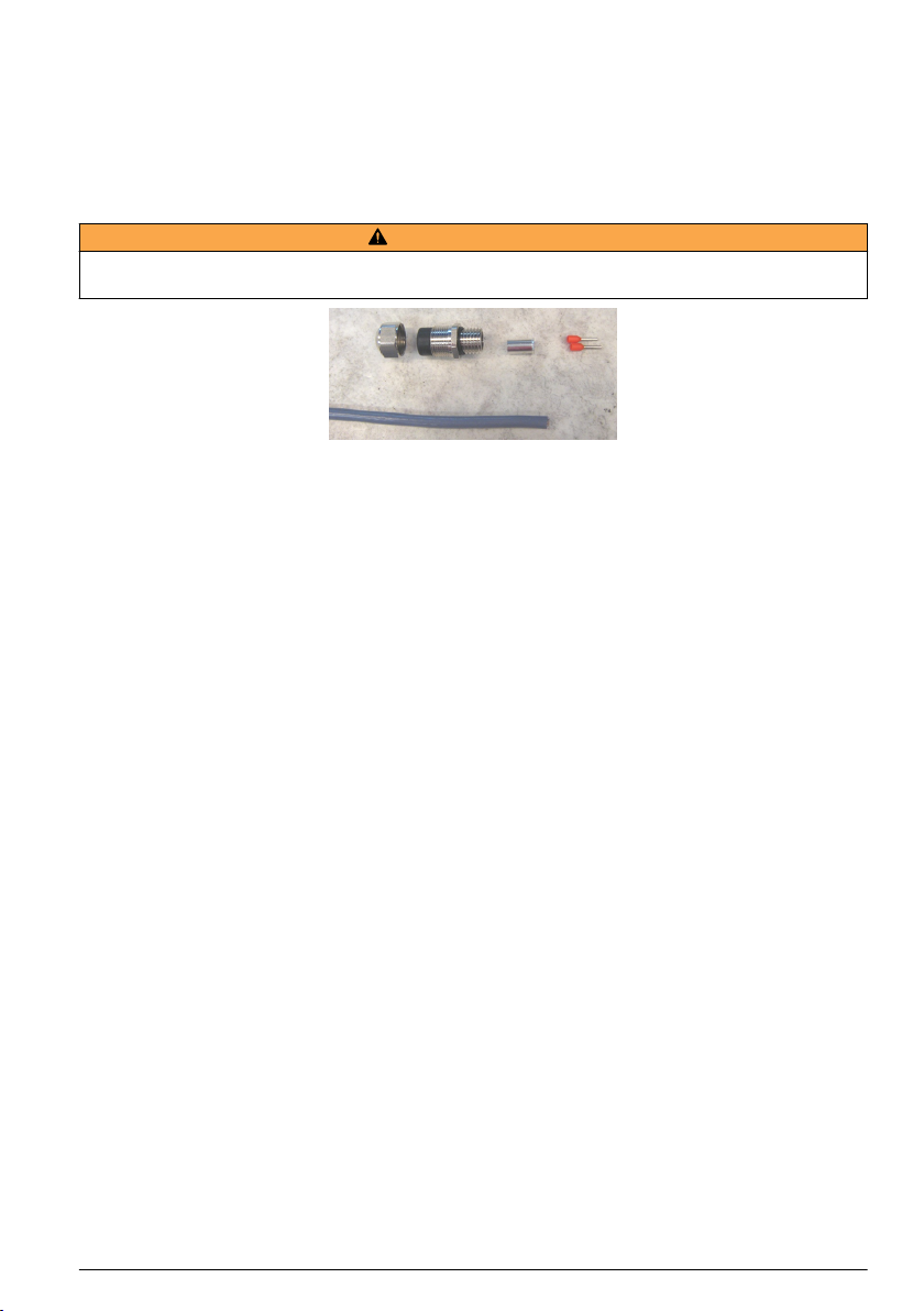
Procedure di cablaggio e preparazione del cavo
Attenersi alla seguente procedura per tutti i cavi che collegano le periferiche (ossia pompe, rilevatori
di livello, allarmi, ecc.) all'unità elettronica (N. 11 nella Figura 1 a pagina 56). Alcuni cavi sono forniti
pronti all'uso. Altri cavi forniti localmente dall'utente devono essere preparati attenendosi alla
procedura descritta in Preparazione del cavo a pagina 59 prima del loro collegamento all'unità
elettronica.
Preparazione del cavo
A V V ER T E N Z A
Per garantire il rispetto delle norme di sicurezza e della conformità EMC dell'analizzatore, attenersi alla seguente
procedura per i cavi utilizzati dall'utente per il collegamento all'unità elettronica dell'apparecchio.
Materiali richiesti:
• Cavo schermato (diametro minimo 4,5 mm - massimo 6 mm) con 2 o 3 fili in base alla funzione
(RS232 = 3 fili, Allarme = 2 fili, ecc.)
• Pressacavo metallico
• Ghiera di messa a terra
• 2 o 3 tappi protettivi per i fili esposti
• Morsetto per la ghiera di messa a terra
• Pinze per crimpatura per i tappi protettivi
Italiano 59
Page 60
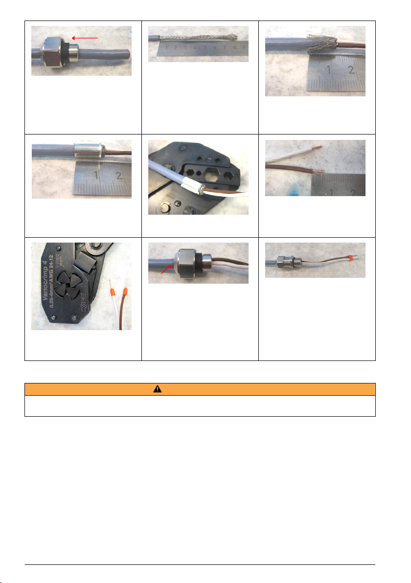
1. Collocare il dado e la
guarnizione metallica del
pressacavo sul cavo schermato.
2. Rimuovere 8 cm di rivestimento
esterno del cavo per esporre la
schermatura intrecciata.
3. Rimuovere la schermatura per
scoprire i fili interni, lasciandone
solo 12 mm che dovranno essere
ripiegati sul cavo.
4. Inserire la ghiera di messa a
terra sulla schermatura.
7. Utilizzare le pinze per
crimpatura per applicare le spine
protettive sui fili.
5. Utilizzare il morsetto per
bloccare la ghiera sul cavo.
8. Spostare la schermatura
metallica sopra la ghiera e
bloccare le due parti insieme
verificando che la ghiera non
rimanga esposta all'estremità del
cavo di schermatura. Spostare il
dado in modo da coprire la
schermatura.
6. Rimuovere 5 mm di rivestimento
isolante dei fili.
9. Passare la parte filettata del
pressacavo sui fili e avvitarla al
dado sul cavo. Il cavo è ora pronto
ad essere collegato, attendendosi
alla procedura descritta in
Collegamento delle periferiche
a pagina 60
Collegamento delle periferiche
A V V ER T E N Z A
Per garantire il rispetto delle norme di sicurezza e della conformità EMC dell'analizzatore, attenersi alla seguente
procedura per il collegamento di tutte le periferiche all'unità elettronica dell'apparecchio.
60 Italiano
Page 61
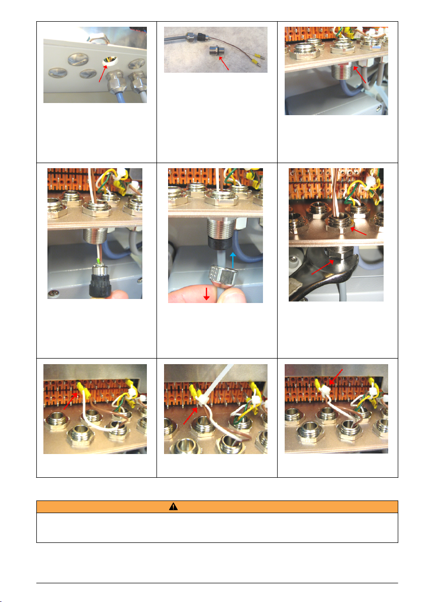
1. Scegliere un'apertura non
utilizzata in prossimità della
connessione del cavo sulla scheda
elettronica. Rimuovere la vite e il
dado, quindi riporre la vite per uso
futuro.
2. Prendere il cavo, svitare la parte
filettata e rimuoverla.
3. Avvitare la parte filettata
nell'apertura selezionata al punto
1 e bloccarla in posizione
utilizzando il dado
precedentemente rimosso.
4. Fare scorre il resto del cavo
attraverso il pressacavo.
7. Collegare i fili ai relativi
terminali.
5. Tirare leggermente il cavo con
una mano fino a quando la
schermatura interna viene a
contatto con il pressacavo.
Stringere il dado sul pressacavo
con l'altra mano.
8. Bloccare i fili con una fascetta.
6. Stringere il dado con una chiave
per bloccarlo in posizione.
Potrebbe essere necessario
utilizzare una seconda chiave per
tenere fermo il dado superiore.
9. Tagliare la fascetta il più vicino
possibile ai fili.
Connessioni dell'elettrodo
A V V ER T E N Z A
Per garantire il rispetto delle norme di sicurezza e della conformità EMC dell'analizzatore, attenersi alla seguente
procedura per il collegamento degli elettrodi selettivi, di riferimento, combinati e di temperatura all'unità elettronica
dell'apparecchio.
Italiano 61
Page 62
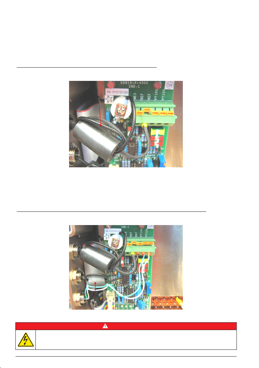
Prima di essere collegati al blocco terminale della scheda di misura, i cavi dell'elettrodo devono
passare attraverso i blocchi in ferrite per ridurre al minimo il rischio di interferenze esterne che
potrebbero compromettere la correttezza dei dati rilevati.
Per l'elettrodo selettivo o combinato, installare il pressacavo e passare il cavo nell'unità elettronica
come per gli altri cavi (come descritto in Collegamento delle periferiche a pagina 60). Quando
entrambi i fili (misura e schermato) sono in posizione, farli scorrere attraverso il blocco in ferrite. Fare
passare i fili una seconda volta attorno al blocco in ferrite prima di collegarli ai relativi ingressi, come
illustrato nella Figura 3.
Figura 3 Collegamento dell'elettrodo selettivo o combinato
Per l'elettrodo selettivo (non applicabile in caso di elettrodo combinato) e il sensore di temperatura,
installare i pressacavi e passare i cavi nell'unità elettronica come nel caso di tutti gli altri cavi (come
descritto in Collegamento delle periferiche a pagina 60). Quando il filo dell'elettrodo di riferimento e i
due fili del sensore di temperatura sono in posizione, farli scorrere attraverso il secondo blocco in
ferrite. Fare passare i fili una seconda volta attorno al blocco in ferrite prima di collegarli ai relativi
ingressi, come illustrato nella Figura 4 (il sensore della temperatura è privo di polarità).
Figura 4 Collegamento del sensore di temperatura e dell'elettrodo di riferimento
Alimentazione elettrica
P E R IC O L O
Pericolo di folgorazione. Quando si eseguono collegamenti elettrici, scollegare sempre l'alimentazione
dello strumento.
62 Italiano
Page 63
P E R IC O L O
Pericolo di folgorazione. È necessario predisporre la messa a terra.
P E R IC O L O
Pericolo di incendio e folgorazione. Individuare con precisione l'interruttore di disconnessione
dell'alimentazione per l'installazione del condotto.
A V V ER T E N Z A
Rischio potenziale di scossa elettrica. Se questo apparecchio viene usato all'esterno o in luoghi
potenzialmente umidi, è necessario utilizzare un interruttore automatico differenziale per collegare
l'apparecchio alla sorgente di alimentazione principale.
A T T EN ZI O N E
Pericoli multipli. Gli interventi descritti in questa sezione del documento devono essere eseguiti solo da
personale qualificato.
Installare il dispositivo in un luogo e in una posizione che forniscano un agile accesso per la disconnessione e il
funzionamento del dispositivo.
L'analizzatore è configurato in fabbrica a 110/120 VAC o 220/240 VAC. Collegare l'analizzatore alla fonte di
alimentazione corretta.
A V V IS O
A V V IS O
Collegare l'apparecchiatura in conformità alle normative elettriche locali, regionali o nazionali
applicabili. Rispettare tutti i codici e/o le normative per il cablaggio. Inserire i cavi nell'armadietto dello
strumento tramite i pressacavi forniti in dotazione.
Utilizzare un cavo di messa a terra schermato per il collegamento alla rete elettrica. Le specifiche per
il cavo di rete sono: diametro compreso tra 7 e 9,5 mm, 3 fili (2 + terra), corrente nominale minima di
10 A, sezione compresa tra 1 mm2 (AWG18) e 2,5 mm2 (AWG14). Per tutti gli altri collegamenti di
segnale, utilizzare un cavo schermato. Utilizzare anche un cavo di messa a terra schermato per i
collegamenti dei segnali.
Nota: L'apparecchiatura destinata al collegamento permanente alla RETE ELETTRICA deve essere predisposta
per il collegamento di un sistema elettrico conforme alle norme ANSI/NFPA 70, NEC e CSA C22.1.
Assicurarsi che nella linea di alimentazione venga installato un interruttore di circuito a 2 poli con una
capacità di interruzione minima di 20 A. Installare un dispositivo di disconnessione locale per lo
strumento entro 3 m (10 piedi) dallo strumento. Applicarvi sopra un'etichetta che identifichi
chiaramente il dispositivo di disconnessione principale dello strumento.
Al termine del cablaggio del sistema, compiere le operazioni seguenti per accenderlo:
1. Aprire la scatola di alimentazione (n. 12 nella Figura 1 a pagina 56).
2. Passare il cavo di alimentazione attraverso il pressacavo e collegare i fili di terra, neutro e sotto
tensione ai terminali 1, 2 e 3, rispettivamente, come indicato nella Figura 5.
Italiano
63
Page 64
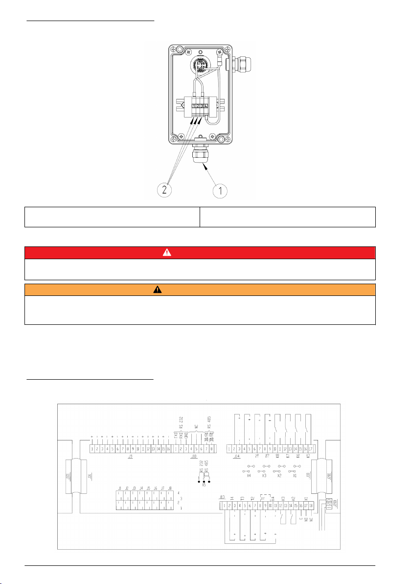
Figura 5 Scatola di alimentazione
1 Pressacavo di alimentazione 2 Terminali di connessione (1 = Terra, 2 = Neutro, 3 =
Sotto tensione)
Collegamento degli ingressi e delle uscite
P E R IC O L O
Pericolo di folgorazione. Verificare sempre che l'analizzatore sia spento e il cavo elettrico sia scollegato prima di
effettuare qualsiasi collegamento descritto in questa sezione.
A V V ER T E N Z A
Per garantire il rispetto delle norme di sicurezza e della conformità EMC dell'analizzatore, attenersi alla procedura
descritta in Procedure di cablaggio e preparazione del cavo a pagina 59 per tutti i collegamenti all'unità elettronica
dell'apparecchio.
Aprire il pannello posteriore dell'unità elettronica (N. 11 nella Figura 1 a pagina 56) per effettuare
queste connessioni. Svitare le quattro viti che trattengono il pannello posteriore dell'unità e aprirlo
delicatamente da sinistra verso destra. Fare riferimento alla Figura 6 per la posizione del terminale e
alle seguenti tabelle per le funzioni.
Nota: Uno schema dei connettori del terminale è riprodotto anche sul retro dell'unità elettronica.
Figura 6 Connettori del terminale
64 Italiano
Page 65
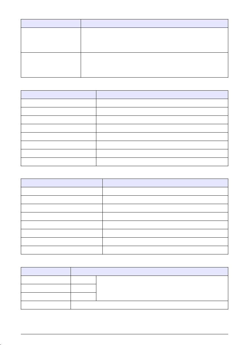
Tabella 1 Scheda microprocessore
Terminale Descrizione
Configurazione relè K5 - K8
X1 - X4
X5
• 2-3: Relè a contatto secco
• 1-2 e 3-4: 24 VDC
Interfaccia seriale
• 1-2: RS 232
• 2-3: RS 485
Tabella 2 Rilevatore del livello e comandi esterni (J1 - J8)
Terminale Utilizzo
J1 Avvio/Standby
J2 Campione esterno
J3 Non utilizzato
J4 Soluzione di condizionamento
J5 Soluzione di titolazione
J6 Soluzione di calibrazione
J7 Pulizia chimica
J8 Campione
Tabella 3 Uscite analogiche (J9)
Terminale Utilizzo
1-2 Uscita analogica 1
3-4 Uscita analogica 2
5-6 Uscita analogica 3
7-8 Uscita analogica 4
9-10 Uscita analogica 5
11-12 Uscita analogica 6
13-14 Uscita analogica 7
15-16 Uscita analogica 8
Tabella 4 Interfaccia seriale (J10)
Terminale Utilizzo
1 TXD
Utente RS 232 configurato con X5 2 RXD
3 GND
4, 5, 6, 7, 8 Non utilizzato
Italiano 65
Page 66
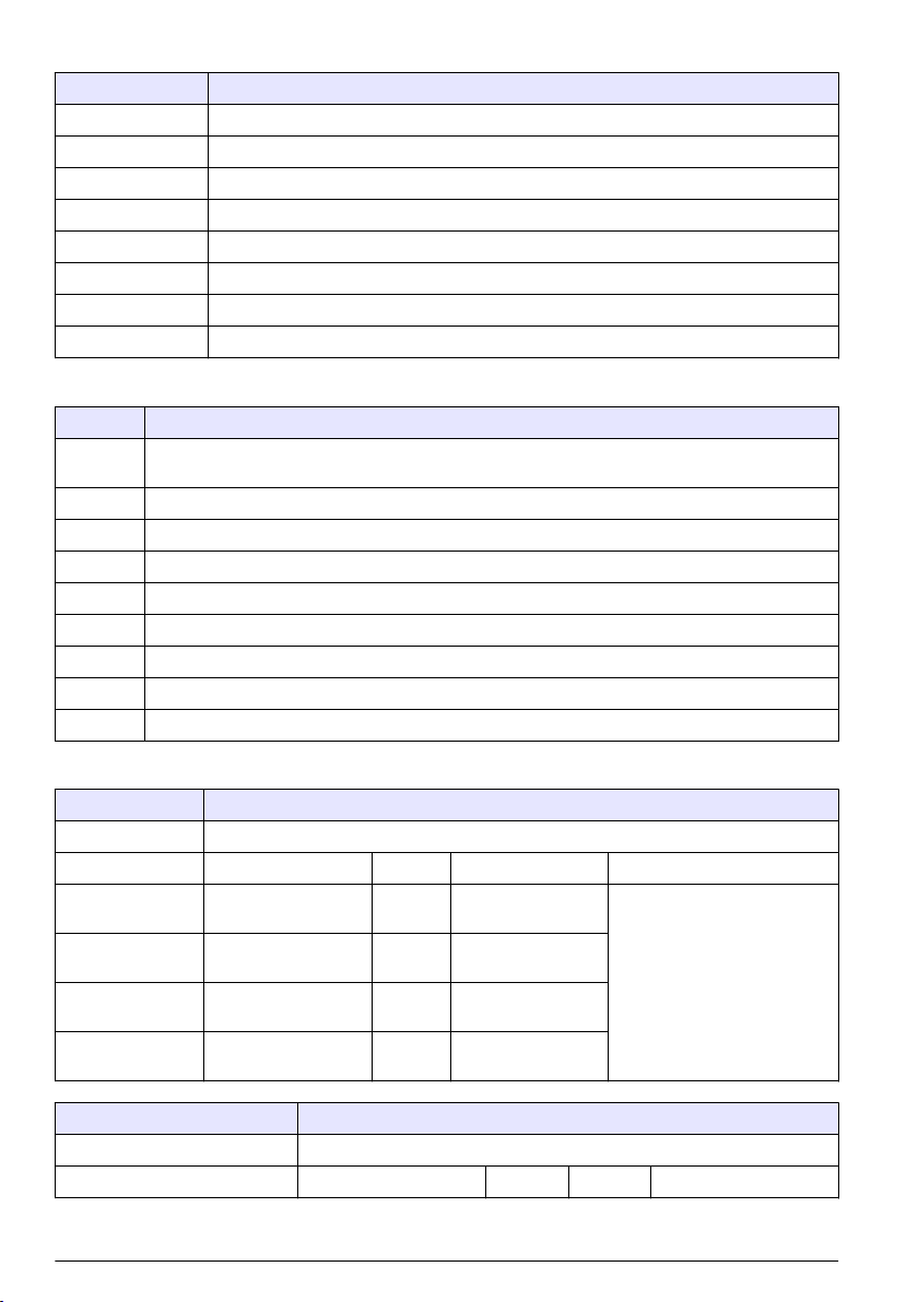
Tabella 5 Accessori 1 (J13)
Terminale Utilizzo
1-11 Sistema di riscaldamento
2-3 Mixer
4-5 Valvola di lavaggio
6-7 Valvola di scarico
8-9 Valvola del campione
12-13 Allarme 2
14-15 Allarme 1
16-17-18 Allarme di sistema (16-17 per NO o 16-18 per NC)
Tabella 6 Accessori 2 (J14)
Terminale Utilizzo
1-11 (8-10) Calibrazione automatica o pompa campione esterno (collegare 8 e 10 e impostare il jumper X4 a
2-3 Non utilizzato
4-5 Valvola di pulizia chimica
6-7 Valvola di diluizione
8-9 Non utilizzato
10-11 Pompa 4
12-13 Pompa 3 (X3 impostato a 1-2 e 3-4)
14-15 Pompa 2 (X2 impostato a 1-2 e 3-4)
16-17 Pompa 1 (X1 impostato a 1-2 e 3-4) / Calibrazione automatica
2-3)
Tabella 7 Funzioni delle pompe 1 - 4
CAL AUTO YES o MANUAL YES
Jumper X4 X4 impostato a 2-3 e una piattina tra 8 e 10 di J14
Pompa 1 Pompa 2 Pompa 3 Pompa 4
1 reattivo di
titolazione / 1 cond.
1 reattivo di
titolazione / 2 cond.
2 reattivi di
titolazione / 1 cond.
2 reattivi di
titolazione / 2 cond.
Jumper X4 X4 impostato tra 1-2 e 3-4 e nessuna piattina tra 8 e 10 di J14
Reattivo di titolazione1 Cond 1
Reattivo di titolazione1 Cond 1 Cond 2
Reattivo di titolazione1 Cond 1 Reattivo di
titolazione 2
Reattivo di titolazione1 Cond 1 Reattivo di
titolazione 2
CAL AUTO NO e MANUAL NO
Pompa 1 Pompa 2 Pompa 3 Pompa 4
CAL AUTO o OTHER SAMPLE
(CAL. AUTO o ALTRO
CAMPIONE)
66 Italiano
Page 67
CAL AUTO NO e MANUAL NO
1 reattivo di titolazione / 1 cond.
1 reattivo di titolazione / 2 cond.
2 reattivi di titolazione / 1 cond.
2 reattivi di titolazione / 2 cond.
Reattivo di titolazione 1 Cond 1 Cond 2 Reattivo di titolazione 2
Allarmi
Fare riferimento anche alla Figura 6 a pagina 64 e alla Tabella 5 a pagina 66. I relè della soglia di
allarme (K2 e K3) sono impostati a normalmente aperto (NO). Il relè di allarme sistema (K1) può
essere impostato a normalmente aperto (terminali 16 e 17) o normalmente chiuso (terminali 16 e 18).
Uscite analogiche
Fare riferimento anche alla Figura 6 a pagina 64 e alla Tabella 3 a pagina 65. Le uscite analogiche
0-20 mA o 4-20 mA sono isolate per galvanizzazione. La seguente tabella mostra l'allocazione delle
diverse uscite:
Analizzatore
I out 1 Terminale 1-2 di J9 Canale di misurazione
I out 2 Terminale 3-4 di J9 Potenziale di misurazione
I out 3 Terminale 5-6 di J9 Non utilizzato
Rilevatore livello campione
Fare riferimento anche alla Figura 6 a pagina 64 e alla Tabella 2 a pagina 65. Il reattore è dotato di
un rilevatore del livello del campione. Collegare il cavo a J8 come indicato di seguito:
Numero terminale J8 Colore
1 Marrone
2 Verde
3 Giallo
4 Bianco
Rilevatore del livello di reagente
Fare riferimento anche alla Figura 6 a pagina 64 e alla Tabella 2 a pagina 65. Ogni contenitore di
reagente è dotato di un rilevatore di livello. Per ogni reagente, collegare i cavi a J4, J5, J6 e J7 come
indicato di seguito:
Numero terminale J4, J5, J6 e J7 Colore
1 Non utilizzato
2 Non utilizzato
3 Marrone
4 Bianco
Connessione RS232
Fare riferimento anche alla Figura 6 a pagina 64 e alla Tabella 4 a pagina 65. Collegare il cavo a
J10 come indicato di seguito:
Italiano
67
Page 68
Numero terminale J10 Spina DB9 Spina DB25
1 (TXD) RXD: 2 RXD: 2
2 (RXD) TXD: 3 TXD: 3
3 (GND) COM: 5 COM: 7
La configurazione del modello 8810 è:
• Velocità: 9600 baud
• Dati: 8 bit
• Bit di stop: 2
• Parità: nessuna
All'avvio l'analizzatore invia il nome e la versione del software:
• ANALYZER 8810 : 00 : 00 : 00 :
• pH X.XX : 00 : 00 : 00 :
Nel modo misurazione, l'analizzatore invia i seguenti dati:
• Titration HH : MM : SS (Titolazione HH:MM:SS)
• M1 XXXXEXX XX.X°C XXX per il primo punto finale
• M2 XXXXEXX XX.X°C XXX per il secondo punto finale
• M3 XXXXEXX XX.X°C XXX per la differenza tra i due punti finali
Dove:
• MX XXXXEXX = valore di misurazione della concentrazione
• XX.X°C = temperatura
• XXX = valore del potenziale
Nel modo rappresentazione grafica, l'analizzatore invia i seguenti dati:
• Plotting HH : MM : SS (Rappresentazione HH:MM:SS)
• P : XX.X°C XXX
Dove:
• XX.X°C = temperatura
• XXX = valore del pH
Dove appropriato, l'analizzatore invia anche i seguenti messaggi completi di timbro orario (HH : MM :
SS)
AZIONI
Cleaning (Pulizia) Pulizia chimica
Stopped (Arresto) Arresto dell'analizzatore
Fix-time (Tempo fisso) Tempo tra due cicli
Standby Analizzatore in standby
AUTO SYS CAL (CALIBRAZIONE SISTEMA AUTOMATICA) Calibrazione automatica
PROCESS SYS CAL (CALIBRAZIONE SISTEMA PROCESSO) Calibrazione di processo
MANUAL SYS CAL (CALIBRAZIONE SISTEMA MANUALE) Calibrazione manuale
68 Italiano
Page 69
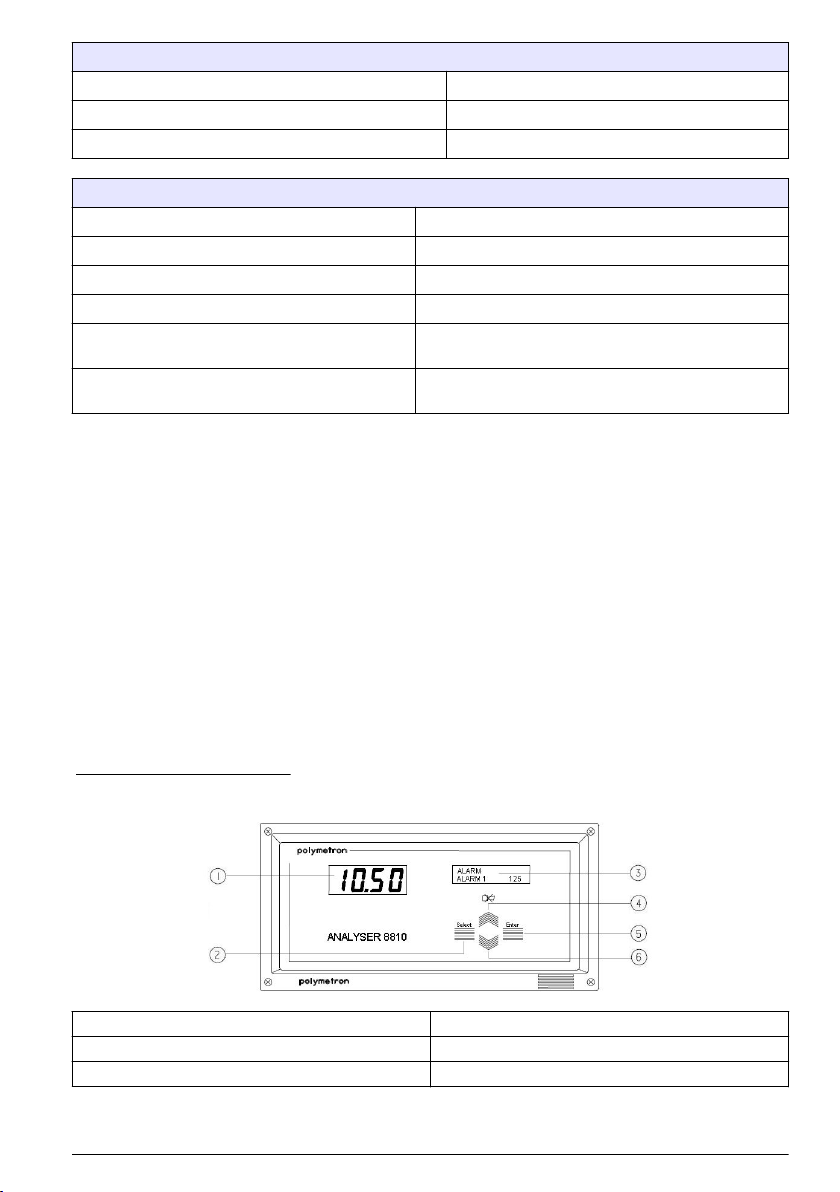
SYSTEM ERRORS (ERRORI DI SISTEMA)
LEVEL SAMPLE (LIVELLO CAMPIONE) Campione assente nella cella di misura
OVER TITR TIME (TITOLAZIONE FUORI TEMPO) Il tempo richiesto per la titolazione è eccessivo
ERROR CALIB (ERRORE CALIBRAZIONE) Errore di calibrazione automatica
AVVERTIMENTI
LEVEL REAGENT (LIVELLO REAGENTE) Reagente di titolazione assente
LEVEL COND (LIVELLO CONDIZIONAMENTO) Reagente di condizionamento assente
LEVEL CALIB (LIVELLO CALIBRAZIONE) Soluzione di calibrazione assente
LEVEL CLEANING (LIVELLO PULIZIA) Soluzione di pulizia assente
RETURN PROCESS (RITORNO PROCESSO) Dopo la misurazione di un campione esterno, questo
SLOPE CALIB 1/2 (CALIBRAZIONE PENDENZA
1/2)
messaggio indica un ritorno alla misurazione di processo
Errore di calibrazione automatica
Accessori aggiuntivi
Tutti gli accessori acquistati, che non sono stati installati in fabbrica, possono essere installati ora. Le
istruzioni per l'installazione e il cablaggio sono riportate nella versione integrale del manuale utente.
Dopo avere installato tutti gli accessori, effettuare i seguenti controlli sulla cella di misura:
• Nessuna parte deve essere a contatto con l'agitatore
• La parte superiore del tubo di tracimazione deve trovarsi circa 2 cm sopra il sifone
• Il rilevatore di livello deve trovarsi circa 1 cm sotto l'ingresso del sifone
• Se non collegato, collegare l'elettrodo di misurazione al cavo più spesso e l'elettrodo di riferimento
a quello più sottile
Interfaccia utente
Descrizione del pannello frontale
L'interfaccia è rappresentata da una tastiera a 4 tasti, un display numerico a 4 cifre e un display
alfanumerico di 2 righe da 16 caratteri.
Figura 7 Pannello anteriore
1 Display numerico 4 Tasto di scorrimento verso l'alto
2 Tasto Select (Selezione) 5 Tasto Enter (Invio)
3 Display alfanumerico 6 Tasto di scorrimento verso il basso
Italiano 69
Page 70

Tasti funzione
• Enter (Invio): consente di richiamare le funzioni o di confermare i parametri.
• Select (Selezione): consente di selezionare le opzioni del menu, di modificare i parametri, di
chiudere i sottomenu e di commutare tra modo comando e operativo.
• Scorrimento verso il basso: Consente di regolare le variabili, di scorrere i display nel modo
operativo e i sottomenu nel modo comando.
• Scorrimento verso l'alto: Simile allo scorrimento verso il basso ma in ordine opposto, consente
anche di annullare l'allarme di sistema.
Modi dell'analizzatore
L'analizzatore funziona in modalità Operating (Operativo) o in modalità Command (Comando). In
modalità Operating l'analizzatore esegue le normali attività di misurazione, calibrazione, ecc.
Usando i tasti di scorrimento è inoltre possibile visualizzare un numero limitato di parametri. Il modo
Command consente invece di programmare l'analizzatore, visualizzare i parametri e testare le
funzioni dell'apparecchio. Come impostazione predefinita, in occasione della prima accensione
l'analizzatore si predispone nel modo Command.
Per accedere al modo Operating dal modo Command, selezionare START (AVVIO) da MAIN
MENU (MENU PRINCIPALE).
Per accedere al modo Command dal modo Operating, premere Select (Selezione) per visualizzare
il comando STOP, quindi
• se si desidera semplicemente visualizzare i parametri al momento impostati, dal comando STOP
usare i tasti di scorrimento per selezionare READING (LETTURA) e premere Enter per circa
3 secondi.
• Se si desidera programmare l'analizzatore o testare le sue funzioni, dal comando STOP premere
Enter quindi di nuovo Enter per confermare. Quindi utilizzare i tasti di scorrimento per selezionare
PROGRAMMING (PROGRAMMAZIONE) e premere Enter per circa 3 secondi.
Display
Display numerico: questo display mostra le misure della concentrazione (predefinito), del potenziale
o della temperatura.
Display alfanumerico: questo display visualizza i messaggi sullo stato e la programmazione
dell'apparecchio. I messaggi variano in base al modo:
• Modo Operating (Operativo): La riga superiore indica le unità, il tipo di misurazione e gli allarmi
attivati. La riga inferiore indica lo stato dell'analizzatore, ad esempio calibrazione. titolazione, ecc.
• Modo Command (Comando) : la riga superiore indica il menu principale. La riga inferiore indica i
sottomenu e le impostazioni dei dati.
Descrizione del menu
MENU PRINCIPALE
Il menu principale consente di accedere alle seguenti funzioni:
• STOP - Premendo Enter il processo di misurazione si interrompe immediatamente.
• START (AVVIO) - Premendo Enter il processo di misurazione si avvia
• STAND-BY - Premendo Enter l'analizzatore si predispone in standby
• PROGRAMMING (PROGRAMMAZIONE) - Consente di programmare l'analizzatore (solo modo
Command - Comando)
• READING (LETTURA) - Consente di visualizzare i parametri (solo modo Operating - Operativo)
Nel modo PROGRAMMING o READING è possibile selezionare le seguenti opzioni utilizzando i tasti
di scorrimento:
• MEASUREMENT (MISURAZIONE) - Parametri di titolazione
70
Italiano
Page 71

• CALIBRATION (CALIBRAZIONE) - Consente di calibrare l'analizzatore
• ANALOG-OUT (USCITA ANALOGICA) - Parametri dell'uscita analogica
• ALARM (ALLARME) - Parametri limite per l'allarme
• SEQUENCE (SEQUENZA) - Modo misurazione
• SERVICE (SERVIZIO) - Consente di controllare il funzionamento dell'analizzatore e degli
accessori
• CLEANING (PULIZIA) - Parametri della pulizia chimica
• SAMPLE COND. (CONDIZIONAMENTO CAMPIONE) - Parametri di condizionamento del
campione
• CAL PARAMETER (PARAMETRO CALIBRAZIONE) - Consente di visualizzare i dettagli della
calibrazione primaria e dell'ultima calibrazione.
• TIMING (SINCRONISMO) - Parametri del ciclo di titolazione
• PM XXXX - Configurazione del sistema (disponibile solo nel modo PROGRAMMING
(PROGRAMMAZIONE); richiede una password valida)
Nota: Alcune delle opzioni sopra elencate sono disponibili solo se il relativo accessorio è stato installato.
Configurazione del sistema (opzione PM XXXX)
Consultare anche i documenti inerenti alla Procedura d'installazione, forniti insieme
all'analizzatore, per informazioni specifiche sull'applicazione.
1. Selezionare PM XXXX con i tasti di scorrimento e premere Enter. Usando il tasto Select per
spostarsi da un numero al successivo, immettere il codice e premere Enter.
Opzione Descrizione
APPLICATION
(APPLICAZIONE)
UNIT (UNITÀ) Selezionare l'unità di concentrazione dall'elenco disponibile. Selezionando
Adjust ADC (Regola ADC) Questa opzione è riservata al personale tecnico Hach Lange.
Selezionare l'applicazione dall'elenco.
USER (UTENTE) è possibile definire un'unità personalizzata, attribuendole una
descrizione di 5 caratteri.
Italiano 71
Page 72

Opzione Descrizione
Adjust Iout (Regola Iout) Selezionare il tipo di uscita (0-20mA o 4-20mA). Collegare un multimetro in
OPTION (OPZIONE) Nell'elenco disponibile, selezionare YES per le opzioni installate/richieste e NO
serie con l'uscita analogica e apportare piccole modifiche al segnale, in base
alle esigenze.
per quelle non installate/non richieste.
Nota: Alcune opzioni richiedono l'installazione di hardware aggiuntivo (es..
AUTO SYS CAL (CALIBRAZIONE SISTEMA AUTOMATICA), CLEANING
(PULIZIA), HEATING (RISCALDAMENTO), ecc.). Per il corretto funzionamento
dell'analizzatore, i componenti hardware devono essere installati prima della
messa in funzione dell'apparecchiatura.
Parametri di titolazione (opzione MEASUREMENT - MISURAZIONE)
Le applicazioni ACID (ACIDO) e BASE (BASE) richiedono un solo set di parametri. Per le altre
applicazioni sono invece richiesti due set di parametri.
1. Selezionare MEASUREMENT (MISURAZIONE) con i tasti di scorrimento e premere Enter.
Opzione Descrizione
PRE-ENDPT1/2 (PUNTO PRE-FINALE 1/2) Impostare il valore del punto pre-finale.
ENDPT1/2 (PUNTO FINALE 1/2) Impostare il valore del punto finale.
Calibrazione (modo CALIBRATION)
Calibrazione nel modo READING (LETTURA)
L'opzione CALIBRATION (CALIBRAZIONE) consente di visualizzare i parametri di calibrazione.
Scorrere l'elenco dei parametri visualizzati.
Calibrazione nel modo PROGRAMMING (PROGRAMMAZIONE)
Sono disponibili tre opzioni:
• PRIMARY CALIBRATION (CALIBRAZ. PRIMARIA)
• SYSTEM CALIBRATION (CALIBRAZ. SISTEMA)
• ELECTRODE CALIBRATION (CAL. ELETTRODO)
Calibrazione primaria o di sistema
Una calibrazione primaria viene eseguita in fabbrica ed è utilizzata come riferimento per le
calibrazioni successive. Di solito, questa calibrazione non deve essere ripetuta a meno che non
vengano apportate importanti modifiche al sistema (ad esempio, la sostituzione di un elettrodo).
Il processo per la calibrazione PRIMARIA o SISTEMA è identico.
1. Nel menu CALIBRATION (CALIBRAZIONE), selezionare PRIMARY CAL (CALIBRAZIONE
PRIMARIA) con i tasti di scorrimento e premere Enter.
Opzione Descrizione
MANUAL SYS CAL (CALIBRAZIONE
SISTEMA MANUALE)
Questa calibrazione richiede l'uso di una soluzione di calibrazione
preparata in laboratorio, la cui concentrazione sia nota.
72 Italiano
Page 73

Opzione Descrizione
PROCESS SYS CAL (CALIBRAZIONE
SISTEMA PROCESSO)
AUTO SYS CAL (CALIBRAZIONE
SISTEMA AUTOMATICA)
Questa calibrazione utilizza la soluzione di processo, con
concentrazione nota, come soluzione di calibrazione.
Questa calibrazione è disponibile solo se la relativa opzione è
stata installata.
Calibrazione manuale
1. Selezionare MANUAL SYS CAL (CALIBRAZIONE SISTEMA MANUALE) e premere Enter.
2. Appare FILL CAL SOL. (RIEMPIRE SOLUZIONE CALIBRAZIONE). Versare la soluzione di
calibrazione nella cella di misura e premere Enter.
3. Appare CONC SOL: XXXXX (CONCENTRAZIONE SOLUZIONE: XXXXX) Digitare la
concentrazione sotto forma di un numero a cinque cifre senza punto decimale o di un numero a
quattro cifre con punto decimale. Premere Enter per confermare.
4. Se si seleziona l'opzione2 INDEP PTS (2 PUNTI INDIPENDENTI) o TWO REAGENTS (DUE
REAGENTI), occorre impostare la concentrazione del secondo punto. Immettere la
concentrazione della seconda soluzione e premere Enter.
Calibrazione di processo
1. Selezionare PROCESS SYS CAL (CALIBRAZIONE SISTEMA PROCESSO) e premere Enter.
2. Appare CONC SOL: XXXXX (CONCENTRAZIONE SOLUZIONE: XXXXX) Digitare la
concentrazione sotto forma di un numero a cinque cifre senza punto decimale o di un numero a
quattro cifre con punto decimale. Premere Enter per confermare.
3. Se si seleziona l'opzione2 INDEP PTS (2 PUNTI INDIPENDENTI) o TWO REAGENTS (DUE
REAGENTI), occorre impostare la concentrazione del secondo punto. Immettere la
concentrazione della seconda soluzione e premere Enter.
Calibrazione automatica
La calibrazione automatica è disponibile solo quando la relativa opzione è installata sull'analizzatore.
Questa opzione consente di eseguire la calibrazione automatica a intervalli pre-programmati,
utilizzando una soluzione di calibrazione la cui concentrazione sia nota.
Nota: Quando si utilizza questa opzione per la prima volta, selezionare NO per IMMEDIATE al punto 3 in modo da
inserire i parametri aggiuntivi richiesti.
1. Controllare il contenuto del contenitore della soluzione di calibrazione. Una calibrazione utilizza
da 250 a 300 mL di soluzione di calibrazione, per cui il contenuto di un contenitore standard
consente di eseguire da 30 a 40 calibrazioni.
2. Selezionare AUTO SYS CAL (CALIBRAZIONE SISTEMA AUTOMATICA) e premere Enter.
Appare IMMEDIATE (IMMEDIATA). Selezionare YES o NO seguito da Enter. Selezionando
YES, la calibrazione automatica si avvia immediatamente. Non occorre impostare altri parametri.
3. Se si seleziona NO, immettere la frequenza (FREQUENCY) di calibrazione. Si tratta del numero
di titolazioni eseguite tra una calibrazione automatica e la successiva.
4. Appare CONC SOL: XXXXX (CONCENTRAZIONE SOLUZIONE: XXXXX) Digitare la
concentrazione sotto forma di un numero a cinque cifre senza punto decimale o di un numero a
quattro cifre con punto decimale. Premere Enter per confermare.
5. Se si seleziona l'opzione2 INDEP PTS (2 PUNTI INDIPENDENTI) o TWO REAGENTS (DUE
REAGENTI), occorre impostare la concentrazione del secondo punto. Immettere la
concentrazione della seconda soluzione e premere Enter.
6. Appare INJ TIME (TEMPO INIEZIONE) Immettere il tempo di iniezione della soluzione di
calibrazione espresso in secondi e confermare con Enter.
Calibrazione dell'ELETTRODO
La calibrazione dell'elettrodo richiede due soluzioni tampone la cui concentrazione sia nota per
eseguire una calibrazione su 2 punti. Le soluzioni tampone devono avere una concentrazione pH
Italiano
73
Page 74
diversa compresa tra 1 e 9, o prossima a quella dell'applicazione. La soluzione tampone 1 deve
avere il valore pH più basso e la soluzione tampone 2 quello più alto.
1. Nel menu CALIBRATION (CALIBRAZIONE), selezionare ELECTRODE CAL (CALIBRAZIONE
ELETTRODO) con i tasti di scorrimento e premere Enter.
Opzione Descrizione
2 POINT (2 PUNTI) Premere Enter per confermare la calibrazione su due punti.
FILL BUFFER 1 (RIEMPIRE
TAMPONE 1)
BUFFER 1: XXXXX (TAMPONE 1:
XXXXX)
FILL BUFFER 2 (RIEMPIRE
TAMPONE 2)
BUFFER 2: XXXXX (TAMPONE 2:
XXXXX)
Riempire la cella di misura con la prima soluzione tampone e
premere Enter.
Digitare il valore pH della prima soluzione tampone e premere
Enter.
Riempire la cella di misura con la seconda soluzione tampone e
premere Enter.
Digitare il valore pH della seconda soluzione tampone e premere
Enter.
Risultati della calibrazione
In PRIMARY CAL (CALIBRAZIONE PRIMARIA) la calibrazione viene sempre considerata corretta e
viene usata come riferimento per le calibrazioni successive. La pendenza è pari al 100%.
Le pendenze delle successive calibrazioni sono confrontare con i valori della calibrazione primaria.
Se i nuovi valori della pendenza sono compresi tra 70 e 130% dei valori correnti, saranno considerati
validi e utilizzati per le successive misurazioni.
Se i nuovi valori della pendenza sono compresi tra 50 e 70% o tra 130 e 150% dei valori attuali, sarà
necessario confermarli ( CONFIRM). Selezionare YES o NO e premere Enter. Selezionando YES i
nuovi valori vengono utilizzati per le successive misurazioni. Selezionando NO (o se i nuovi valori di
pendenza sono <50% o >150% dei valori correnti) appare il messaggio ERROR CALIB (ERRORE
CALIBRAZIONE). Premere Enter per continuare.
CAL ERROR (ERRORE CALIBRAZIONE) indica che la calibrazione è errata. Selezionare RETRY
(RIPROVA) per ripetere la calibrazione o ABORT (ANNULLA) per annullarla.
Nella calibrazione automatica lo strumento non richiede alcuna conferma da parte dell'operatore.
Tuttavia, se la deviazione della pendenza è <50% o >150% dei valori correnti, sul display appare un
messaggio di avvertimento SLOPE CALIB ! (CALIBRAZIONE PENDENZA !)
Uscite analogiche (opzione ANALOG-OUT)
L'analizzatore dispone di due uscite analogiche che vengono assegnate in base all'applicazione:
Applicazione Uscita analogica 1 Uscita analogica 2
ACID (ACIDO) pH della concentrazione acida all'avvio della titolazione
BASE (BASE) pH della concentrazione base all'avvio della titolazione
FREE/TOTAL ACID (ACIDO
LIBERO/TOTALE)
FREE/TOTAL BASE (BASE
LIBERA/TOTALE)
2p-m p 2p-m
74 Italiano
FREE (LIBERO) TOTAL (TOTALE)
FREE (LIBERA) TOTAL (TOTALE)
Page 75
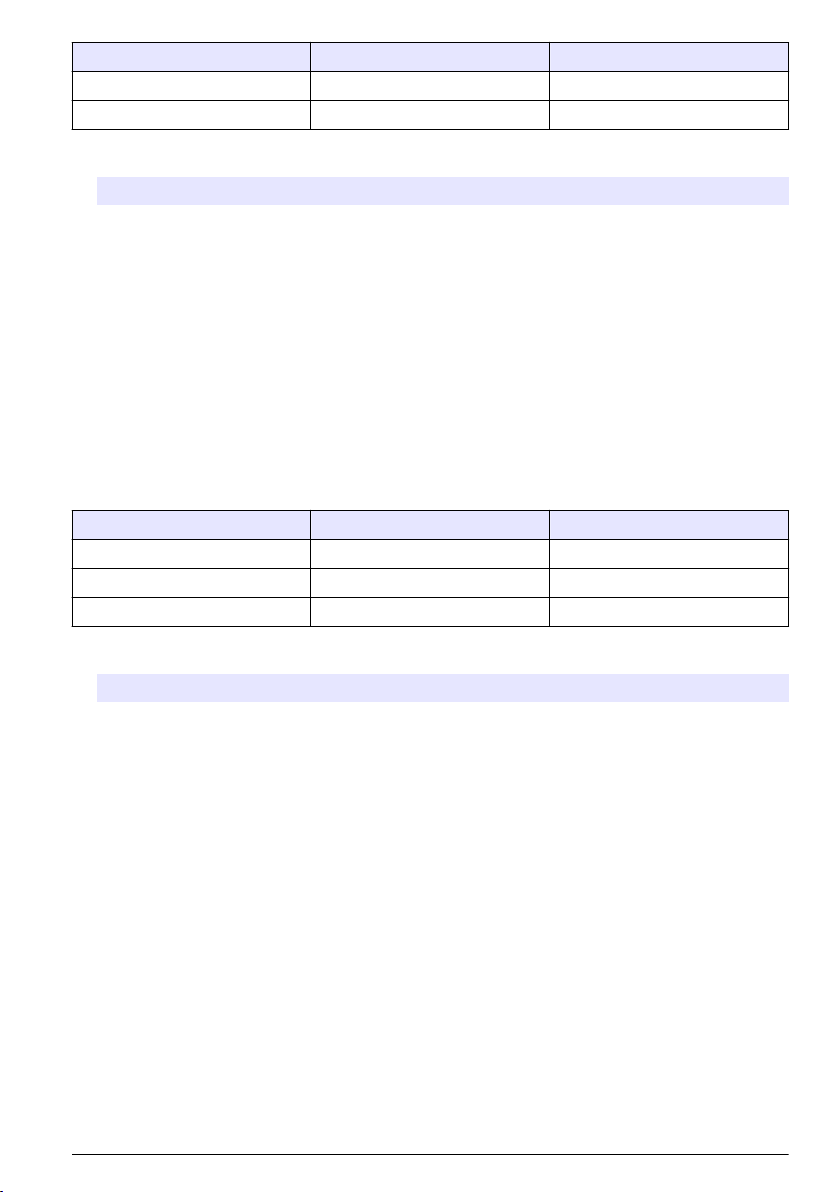
Applicazione Uscita analogica 1 Uscita analogica 2
x(p-m) m x(p-m)
x(m-p) p x(m-p)
1. Selezionare ANALOG-OUT (USCITA ANALOGICA) con i tasti di scorrimento e premere Enter.
Opzione Descrizione
START I1/2 (AVVIO I1/2) Immettere il valore corrispondente all'uscita di corrente 0/4 mA.
END I1/2 (FINE I1/2) Immettere il valore corrispondente all'uscita di corrente 20 mA.
Conc (Concentrazione) Consente di eseguire un test sull'uscita inviando la corrente corrispondente
Full (Massima) Consente di eseguire un test sull'uscita inviando la corrente massima di 20 mA.
Zero Consente di eseguire un test sull'uscita inviando la corrente minima di 0 o 4 mA,
Nota: È possibile uscire da questo menu solo quando è visualizzata l'opzione Conc.
all'ultimo valore misurato.
in base alla configurazione dell'analizzatore.
Impostazione degli allarmi e delle soglie (opzione ALARM - ALLARME)
L'analizzatore dispone di tre allarmi che vengono assegnati in base all'impostazione di
WARNING/R1(AVVERTIMENTO/R1):
WARNING/R1 impostato a NO WARNING/R1 impostato a SI
Allarme di sistema Allarme di sistema e di avvertimento Solo allarme di sistema
Allarme 1 Allarme 1 Allarme di avvertimento
Allarme 2 Allarme 2 Allarme 1 e 2
1. Selezionare ALARM (ALLARME) con i tasti di scorrimento e premere Enter.
Opzione Descrizione
SYS.ALARM ON/OFF (ALLARME
SISTEMA ON/OFF)
WARNING/R1 YES/NO
(AVVERTIMENTO/R1 SI/NO)
ALARM 1/2 ON/OFF (ALLARME
1/2 ON/OFF)
ALARM 1/2 XXX/XXX (ALLARME
1/2 XXX/XXX)
Attiva o disattiva l'allarme di sistema.
Definisce l'assegnazione dell'allarme (vedere la precedente
tabella).
Attiva o disattiva gli allarmi 1 e 2.
Quando attivato, definisce quale misura fa scattare l'allarme
(specifico dell'applicazione).
Italiano 75
Page 76

Opzione Descrizione
ALARM 1/2 HIGH/LOW (ALLARME
1/2 ALTO/BASSO)
ALARM 1/2 XXX (ALLARME 1/2 XXX) Digitare il valore di soglia. Se l'allarme è impostato a HIGH
Quando attivato, definisce se l'allarme scatta con un valore di
misura alto o basso.
(ALTO), qualsiasi valore misurato che superi questa soglia farà
scattare l'allarme, oppure se l'allarme è impostato a LOW
(BASSO) qualsiasi valore misurato che sia al di sotto di questa
soglia farà scattare l'allarme.
Modo misurazione (opzione SEQUENCE - SEQUENZA)
Consente di impostare il modo di misurazione.
1. Selezionare SEQUENCE (SEQUENZA) con i tasti di scorrimento e premere Enter. Utilizzare i
tasti di scorrimento per selezionare il modo richiesto.
Opzione Descrizione
FIX TIME (TEMPO
FISSO)
LOOP (CICLO
CONTINUO)
PLOT pH (GRAFICO
pH)
Un intervallo prefissato tra le misurazioni. L'intervallo è impostato in Parametri del
ciclo di misurazione (opzione TIMING - SINCRONISMO) a pagina 77.
Misurazione continua. Non occorre impostare altri parametri.
Selezionare questa opzione se si desidera tracciare una curva di titolazione.
Immettere i valori START pH (pH INIZIALE) e END pH (pH FINALE) (tra 0 e 14)
che definiscono le uscite 0/4mA e 20mA. Se è stata selezionata l'opzione TWO
REAGENTS (DUE REAGENTI), definire quale reagente sarà utilizzato per la
pendenza.
Test dell'analizzatore e degli accessori (opzione SERVICE - SERVIZIO)
Consente di verificare che le varie opzioni (es. pompe) funzionino correttamente. L'elenco include
anche l'opzione che consente di visualizzare il numero di versione dell'ultimo software installato.
1. Selezionare SERVICE (SERVIZIO) con i tasti di scorrimento e premere Enter.
2. Selezionare l'opzione da sottoporre a test e impostarla a ON per avviarla, controllare che funzioni
correttamente, quindi impostarla a OFF per fermarla.
Pulizia chimica (opzione CLEANING - PULIZIA)
Questa opzione viene visualizzata solo se l'opzione CLEANING è attivata.
Consente di definire i parametri per la pulizia chimica del sistema.
1. Selezionare CLEANING con i tasti di scorrimento e premere Enter.
Opzione Descrizione
FREQUENCY (FREQUENZA) Impostare il numero di misurazioni tra ogni pulizia chimica.
SPRINKLER (SPRUZZATORE) Definisce la durata (in secondi) dell'operazione di lavaggio cui viene
REAG. INJ (INIEZIONE
REAGENTE)
RESIDENC. (PERMANENZA) Definisce per quanto tempo (in secondi) la soluzione di pulizia rimane
sottoposta la cella di misura.
Definisce la durata (in secondi) dell'operazione di iniezione della soluzione
di pulizia nella cella di misura.
nella cella di misura.
Condizionamento del campione (opzione SAMPLE COND)
Questa opzione viene visualizzata solo se l'opzione SAMPLE COND (CONDIZIONAMENTO
CAMPIONE) è attivata.
76
Italiano
Page 77

Consente di definire i parametri richiesti per il condizionamento del campione prima della
misurazione. È possibile selezionare 1 o 2 reagenti di condizionamento.
1. Selezionare SAMPLE COND con i tasti di scorrimento e premere Enter.
Opzione Descrizione
REAGENT 1/2 OFF/ON (REAGENTE
1/2 OFF/ON)
INJ. REAG. 1/2 (INIEZIONE
REAGENTE 1/2)
TIME REAG. 1/2 (TEMPO
REAGENTE 1/2)
Impostare ON se il condizionamento viene eseguito usando questo
reagente.
Definisce la durata (in secondi) dell'operazione di iniezione del
reagente nella cella di misura.
Definisce per quanto tempo (secondi) il reagente rimane nel
campione prima della misurazione.
Visualizzazione dei dettagli di calibrazione (opzione CAL PARAMETER PARAMETRO CALIBRAZIONE)
Questa opzione consente di visualizzare i dettagli della prima e dell'ultima calibrazione eseguite
dall'analizzatore.
1. Selezionare CAL PARAMETER (PARAMETRO CALIBRAZIONE) con i tasti di scorrimento e
premere Enter.
2. Utilizzare i tasti di scorrimento per selezionare LAST CAL (ULTIMA CAL.) o PRIMARY CAL
(CAL. PRIMARIA), quindi scorrere i dettagli premendo Enter.
Parametri del ciclo di misurazione (opzione TIMING - SINCRONISMO)
Consente di definire i parametri per ogni misurazione.
1. Selezionare TIMING (SINCRONISMO) con i tasti di scorrimento e premere Enter.
Opzione Descrizione
SAMPLE TIME (TEMPO
CAMPIONE)
SPRINKLER N (SPRUZZATORE N) Consente di definire il numero di risciacqui richiesti.
SPRINKLER t (t SPRUZZATORE) Consente di definire la durata (in secondi) di ogni risciacquo.
INJECT TIME (TEMPO INIEZIONE) Consente di definire il tempo (in secondi) in cui il reagente viene
DELAY TIME (INTERVALLO) Consente di definire l'intervallo (in secondi) tra ogni iniezione.
CYCLE TIME (TEMPO CICLO) Consente di definire la durata (in minuti) del ciclo di misurazione.
LIM. TIT. t (LIMITE t TITOLAZIONE) Consente di definire la durata massima (in minuti) di una titolazione.
Consente di definire il tempo (in secondi) in cui il campione viene
iniettato nella cella di misura.
iniettato nel campione.
In caso di superamento del tempo impostato, scatta un allarme di
sistema.
Manutenzione
P E R IC O L O
Pericolo di folgorazione. Verificare che l'analizzatore sia spento e che il cavo di alimentazione sia scollegato
prima di eseguire qualsiasi intervento di manutenzione sull'analizzatore.
Generale
Per la manutenzione periodica, è possibile accedere facilmente a tutti gli elementi dal pannello
frontale.
Italiano
77
Page 78

Per l'installazione degli accessori e il lavoro di assistenza specializzato, è possibile accedere
all'interno dell'analizzatore da tutti i suoi lati, con alcune semplici mosse. È possibile raggiungere e
rimuovere le unità analitiche e di controllo elettronico dopo avere aperto il fronte dell'analizzatore con
l'apposita chiave in dotazione.
Programma di assistenza
Il programma varia in funzione del tipo di applicazione. In termini generali, le seguenti attività
richiedono un intervento mensile:
• Controllo dei contenitori del reagente e delle sostanze chimiche. Riempimento dei contenitori, se
necessario.
• Scollegamento ed eventuale sostituzione dei tubi
• Ogni 2 mesi sostituzione di tutti i tubi
• Controllo della cella di misura e degli elettrodi per eventuali depositi di sostanza. Pulizia se
visibilmente sporchi.
• Controllo di tutti i collegamenti dei tubi per eventuali perdite.
• Verifica del corretto funzionamento del sistema. Calibrazione, se necessaria.
Pulizia e decontaminazione
L'analizzatore non richiede, di norma, alcuna pulizia o decontaminazione.
Se necessario, pulire le superfici esterne dello strumento con un panno umido e una soluzione
detergente neutra. Non utilizzare agenti di pulizia come trementina, acetone o altri prodotti simili per
pulire lo strumento, incluso il display e gli eventuali accessori.
Spegnimento
Arresto del ciclo di misurazione
Selezionare STOP nel menu principale e premere Enter. Appare il messaggio e stopped
(ARRESTATO).
Spegnimento breve (es. weekend)
Selezionare STAND BY nel menu principale e premere Enter per predisporre il sistema in una
condizione di standby definita. La cella di misura viene svuotata, risciacquata e riempita con acqua di
lavaggio.
Spegnimento prolungato
Se il sistema viene spento per un lungo periodo, è necessario pulire gli elettrodi e lavare la cella di
misura. È quindi preferibile rimuovere gli elettrodi e riporli in una soluzione tampone fino al riavvio del
sistema. In nessun caso gli elettrodi devono essere lasciati in una cella di misura vuota, poiché
potrebbero essiccarsi e danneggiarsi. Infine, spegnere l'apparecchio.
78
Italiano
Page 79
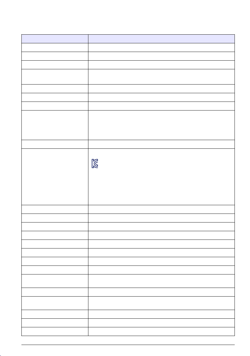
Spécifications
Les spécifications peuvent faire l’objet de modifications sans préavis.
Spécification Détails
Température ambiante 5 à 40 °C (41 à 104 °F)
Humidité relative 10 à 80 %
Altitude de fonctionnement De 0 à 2 000 m. (6 550 pieds) au-dessus du niveau de la mer
Alimentation électrique 110 / 220 / 240 VCA c.a., 50 - 60 Hz, ± 10 %
Fusibles : 110 à 120 V, T630mAL250V ; 220 V à 240 V, T1.25AL250V
Consommation maximale 110 VA
Catégorie de surtension 2 (suivant norme EN 61010-1)
Degré de pollution 2
Conformité CE EN61326-1 : Directive CEM
Remarque : Ce produit appartient à la classe A. Dans un environnement domestique, ce
produit peut provoquer des interférences radio auquel cas, l'utilisateur peut être amené à
prendre des mesures adéquates.
EN61010-1 : Directive basse tension
Agrément ETL ETL, conforme à UL 61010-1 et CSA 22.2 nNº 61010-1
Certification Coréenne
Air comprimé 4 - 7 bar, filtré et séché
Pression d'eau de rinçage 0,5 à 6 bar
Réactifs Bouteille de stockage de 10 L litres (fournie)
Sorties analogiques Nombre : 2 ; 0 - 20 ou 4 - 20 linéaire programmable
Alarmes 2 x relais (concentration) ; 1 x avertissement ou alarme système
Capteurs échangeables pH + électrode de référence
Compensation de température Pt100
Contrôle de niveau Echantillon ; réactifs ; solution d'étalonnage ; nettoyage chimique
Pompes Pompes péristaltique, piston micro, à impulsion ou volumétrique pour
Tuyaux Tygon® ; polyéthylène
Consommation d'agent de
réaction
Temps de titrage Spécifique à l'application
Temps de cycle Programmable jusqu'à 999 minutes
Précision < ± 2 à 4 % (spécifique à l'application)
User Guidance for EMC Class A Equipment
업무용을 위한 EMC 등급 A 장치에 대한
사용자 지침
사용자안내문
A 급 기기 ( 업무용 방송통신기자재 )
이 기기는 업무용 (A 급 ) 전자파적합기기로서 판매자 또는 사용자는 이 점을
주의하시기 바라며 , 가정외의 지역에서 사용하는 것을 목적으로 합니다.
l'étalonnage et les réactifs de conditionnement
Spécifique à l'application
Français 79
Page 80
Spécification Détails
Reproductibilité < ± 2 à 4 % (spécifique à l'application)
Lignes d'échantillon 1
Température d'échantillon 0 à 50 °C (32 à 122 °F)
Pression d'échantillon 0,5 à 6 bar
Débit d’échantillon 40 à 300 litres L/heure
Volume échantillon/cycle 200 à 1 000 ml (ajustable)
Montage panneau 743 x 482 x 122 mm (H x L x P) ; < 20 kg
Armoire (IP 54) 1 900 x 600 x 400 mm (H x L x P) ; < 100 kg
Niveau de puissance sonore
maximal
≤ 80 dBA
Généralités
En aucun cas le constructeur ne saurait être responsable des dommages directs, indirects, spéciaux,
accessoires ou consécutifs résultant d'un défaut ou d'une omission dans ce manuel. Le constructeur
se réserve le droit d'apporter des modifications à ce manuel et aux produits décrits à tout moment,
sans avertissement ni obligation. Les éditions révisées se trouvent sur le site Internet du fabricant.
Consignes de sécurité
A V I S
Le fabricant décline toute responsabilité quant aux dégâts liés à une application ou un usage inappropriés de ce
produit, y compris, sans toutefois s'y limiter, des dommages directs ou indirects, ainsi que des dommages
consécutifs, et rejette toute responsabilité quant à ces dommages dans la mesure où la loi applicable le permet.
L'utilisateur est seul responsable de la vérification des risques d'application critiques et de la mise en place de
mécanismes de protection des processus en cas de défaillance de l'équipement.
Veuillez lire l'ensemble du manuel avant le déballage, la configuration ou la mise en fonctionnement
de cet appareil. Respectez toutes les déclarations de prudence et d'attention. Le non-respect de
cette procédure peut conduire à des blessures graves de l'opérateur ou à des dégâts sur le matériel.
Assurez-vous que la protection fournie avec cet appareil n'est pas défaillante. N'utilisez ni n'installez
cet appareil d'une façon différente de celle décrite dans ce manuel.
Interprétation des indications de risques
D A N GE R
Indique une situation de danger potentiel ou imminent qui, si elle n'est pas évitée, entraîne des blessures graves,
voire mortelles.
A V E R T I S S E M E N T
Indique une situation de danger potentiel ou imminent qui, si elle n'est pas évitée, peut entraîner des blessures
graves, voire mortelles.
Indique une situation de danger potentiel qui peut entraîner des blessures mineures ou légères.
Indique une situation qui, si elle n'est pas évitée, peut occasionner l'endommagement du matériel. Informations
nécessitant une attention particulière.
80 Français
A T T EN T I O N
A V I S
Page 81
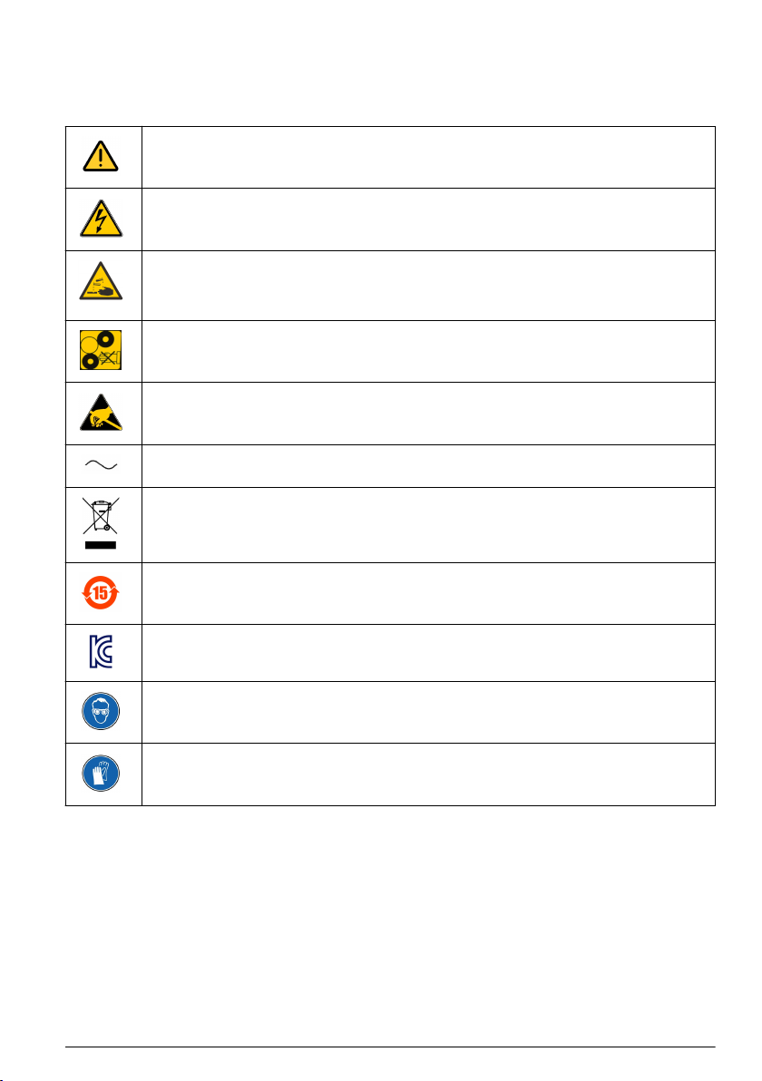
Étiquettes de mise en garde
Lisez toutes les étiquettes fixées au produit. Dans le cas contraire, des blessures ou des dégâts au
produit peuvent se produire. Un symbole sur l'appareil est désigné dans le manuel avec une
instruction de mise en garde.
Lorsqu'il est apposé sur un produit, ce symbole indique un risque potentiel qui pourrait provoquer
des dommages corporels graves et/ou la mort. L'utilisateur doit se référer à ce manuel d'instructions
pour l'utilisation et/ou les informations de sécurité.
Ce symbole, apposé sur un boîtier ou sur une barrière, indique qu'un risque de choc électrique
et/ou d'électrocution existe et indique que seules les personnes qualifiées pour travailler avec des
tensions dangereuses sont habilitées à ouvrir le boîtier ou à enlever une barrière.
Ce symbole identifie la présence d’une substance fortement corrosive ou autre substance
dangereuse et donc, un risque de blessure chimique. Seuls les individus qualifiés et formés pour
travailler avec des produits chimiques doivent manipuler des produits chimiques ou procéder à des
travaux de maintenance sur les systèmes de distribution chimique associés à l’équipement.
Les produits marqués par ce symbole indiquent un risque de pincement des doigts.
Ce symbole, apposé sur le produit, indique la présence de dispositifs sensibles aux décharges
électrostatiques et indique que des précautions doivent être prises pour éviter de les endommager.
Ce symbole, apposé sur un produit, indique que l'instrument est raccordé au courant alternatif.
Le matériel électrique portant ce symbole ne doit pas être mis au rebut dans les réseaux
domestiques ou publics européens. Retournez le matériel usé ou en fin de vie au fabricant pour une
mise au rebut sans frais pour l'utilisateur.
Ce symbole, apposé sur les produits, indique que le produit contient des substances ou éléments
toxiques ou dangereux. Le numéro à l'intérieur du symbole indique la période d'utilisation en
années pour la protection de l'environnement.
Ce symbole, apposé sur les produits, indique que le produit est conforme aux normes CEM
appropriées de la Corée du Sud.
Ce symbole, s'il est apposé sur le produit, indique la nécessité de porter une protection pour les
yeux.
Ce symbole indique la nécessité de porter des protections pour les mains
Aperçu de l'analyseur
L'analyseur ISE POLYMETRON Model 8810 est un système modulaire utilisé pour les mesures ISE
pour une large gamme d'applications industrielles en ligne. L'analyseur collecte automatiquement
des échantillons en ligne, ajoute les produits chimiques appropriés (réactifs, tampons, agents
masquants) et effectue l'analyse. L'analyseur s'applique aux environnements industriels lourds et en
ligne.
Il existe une version montée sur panneau standard. Sont également disponibles des coffrets en
polyester autonomes ou pour fixation murale afin d'abriter l'analyseur avec les réactifs nécessaires.
Les modules hydrauliques sont installés sous l'unité de régulation électronique pour plus la
protection, la facilité d'accès et les tâches de maintenances. Le panneau articulé bascule vers l'avant
pour pouvoir accéder à l'arrière. Reportez-vous à la section Figure 1 pour obtenir l'aperçu du produit.
Français
81
Page 82
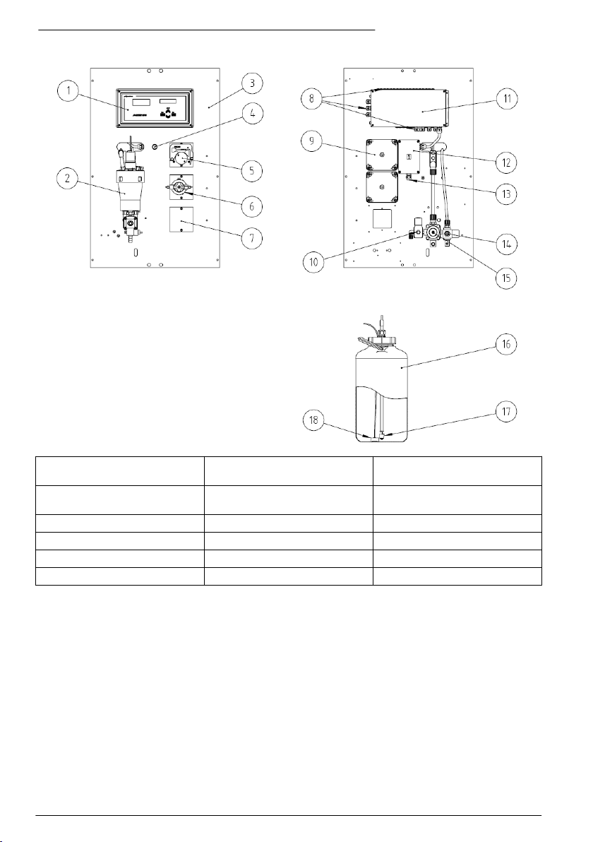
Figure 1 Vue de face et de dos (montage sur panneau illustré)
1 Unité de commande 7 Espace pour pompe
2 Chambre de mesure (voir
Figure 2 à la page 83)
3 Panneau 19 pouces 9 Couvercle de pompe de réactif 15 Robinet d'échantillon
4 Interrupteur principal 10 Robinet d'air comprimé 16 Bouteille de réactif
5 Pompe péristaltique 11 Unité électronique (arrière) 17 Détecteur de niveau
6 Pompe à micro piston 12 Boîtier d'alimentation électrique 18 Lest de tube
supplémentaire
8 Branchements des
entrées/sorties
13 Branchement de l'alimentation
électrique
14 Robinet de rinçage
Chambre de mesure
Reportez-vous à la section Figure 2 pour les composants de la chambre de mesure.
82
Français
Page 83
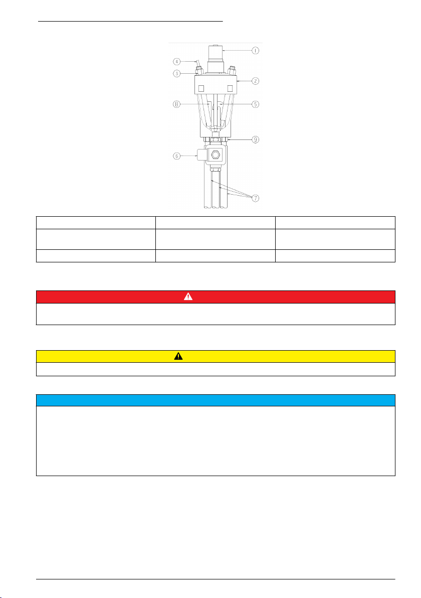
Figure 2 Composants de la chambre de mesure
1 Moteur d’agitateur 4 Câble d'électrode 7 Tube de vidange
2 Couvercle de la chambre de
mesure
3 Electrode 6 Robinet de vidange 9 Raccords filetés
5 Siphon 8 Tube de trop-plein
Montage
D A N GE R
Dangers multiples. Seul le personnel qualifié doit effectuer les tâches détaillées dans cette section du document.
L'alimentation ne doit être branchée qu'après la fin de l'installation et de la vérification.
Installation mécanique
A T T EN T I O N
Dangers multiples. Seul le personnel qualifié doit effectuer les tâches détaillées dans cette section du document.
Montage de l'analyseur
L'analyseur doit être monté le plus proche possible de l'entrée de l'échantillon et doit être placé dans un lieu
facilement accessible pour faciliter le contrôle périodique du débit d'échantillon, ainsi que pour l'entretien régulier.
Dans un boîtier d'environnement assurant la protection contre les précipitations et la lumière solaire directe, avec
une bonne ventilation et un bon contrôle de température en cas d'installation à l'extérieur. Lorsque l’analyseur est
destiné à être monté, il est important de noter qu’il doit être placé en position verticale avec l'unité électronique
(nº 1 sur la Figure 1 à la page 82) sur le dessus. Il est recommandé d’utiliser un niveau à bulle pour s'assurer que
l'analyseur est positionné correctement et ne penche pas d'un côté. Ceci est essentiel pour garantir la précision
de l'analyseur.
Montage sur panneau
Ce modèle est conçu comme système pour baie 19 pouces (48,26 cm). Si vis M6 sont fournies pour
le montage du panneau sur une baie. Tous les branchements internes sont préparés en usine. Les
bouteilles des réactifs peuvent être montées dans un bac de stockage en option.
Montage mural
Tous les branchements internes sont préparés en usine. Les câbles et les tuyaux sont vissés grâce
aux presse-étoupes situés sur le fond à droite de l'armoire. Les bouteilles des réactifs peuvent être
montées dans un bac de stockage en option.
A V I S
Français
83
Page 84
Pour ouvrir l'armoire, pousser le couvercle à poignée vers le haut, appuyer sur le bouton de
verrouillage, puis ouvrir la porte en tournant la poignée de 45° à gauche. Pour accéder à l'intérieur de
l'armoire, retirer la vis moletée sur le côté droit du panneau et tourner soigneusement le panneau
latéralement à gauche en prenant soin de ne coincer aucun tuyau.
Raccordements hydrauliques
D A N GE R
Dangers chimiques ou biologiques. Si cet instrument est utilisé pour la surveillance d'un procédé de
traitement et/ou d'un système de dosage de réactifs chimiques auxquels s'appliquent des limites
réglementaires et des normes de surveillance motivées par des préoccupations de santé et de sécurité
publiques ou de fabrication et de transformation d'aliments ou de boissons, il est de la responsabilité de
l'utilisateur de cet instrument qu'il connaisse et applique les normes en vigueur et qu'il ait à sa
disposition suffisamment de mécanismes pour s'assurer du bon respect de ces normes dans
l'éventualité d'un dysfonctionnement de l'appareil.
Échantillon
L'échantillon entre dans l'analyseur par un tuyau de 12/14 mm (nº 15 sur la Figure 1 à la page 82).
Le débit doit être compris entre 40 et 300 litres/heures à une pression comprise entre 0,5 et 6 bar.
Eau de rinçage
L'eau de rinçage entre dans l'analyseur par un tuyau de 6/8 mm (nº 14 sur la Figure 1 à la page 82).
La pression de l'eau doit être comprise entre 1 et 6 bar.
Réactifs
Les bouteilles de réactifs sont raccordées à la pompe conformément aux instructions correspondant
à l'application.
Vidange
L'échantillon analysé est vidangé à la pression atmosphérique par un tuyau de 12 mm (nº 7 sur la
Figure 2 à la page 83) fourni avec l'analyseur pour la mise en marche initiale. S'assurer qu'aucun
retour de flux ne se produit dans ce tube ni dans les deux autres tubes de vidange (trop-plein nº 8
sur la Figure 2 à la page 83 et siphon nº 5 sur la Figure 2 à la page 83).
Remarque : Avec le modèle armoire, les trois tubes effectuent la vidange dans un réceptacle avec une sortie de
50 mm.
Branchement de l'air comprimé
L'analyseur a besoin d'air comprimé sec et filtré à une pression de 4 à 7 bar. Cet air doit être fourni
au robinet (nº 10 sur la Figure 1 à la page 82) à l'aide d'un tube en plastique approprié de 4/6 mm de
diamètre.
Installation électrique
D A N GE R
Dangers multiples. Seul le personnel qualifié doit effectuer les tâches détaillées dans cette section du document.
Risque d'électrocution. Toujours s'assurer que l'analyseur est hors tension et que l'alimentation est débranchée
avant d'effectuer des branchements électriques.
Risque d'électrocution. Un raccordement à la terre est nécessaire.
Procédures de câblage et préparation du câble
La procédure suivante doit être respectée pour tous les câbles de branchement des périphériques
(par ex. pompes, détecteurs de niveau, alarmes, etc.) sur l'unité électronique (nº 11 sur la Figure 1
à la page 82). Certains câbles sont fournis prêt à l'emploi. Les autres câbles qui seront fournis par
l'utilisateur devront être préparés conformément à la procédure expliquée dans Préparation du câble
à la page 85 avant le branchement à l'unité électronique.
84
Français
D A N GE R
D A N GE R
Page 85
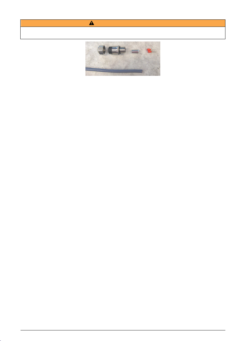
Préparation du câble
A V E R T I S S E M E N T
Pour se conformer aux normes de sécurité et respecter la conformité CEM de l'analyseur, cette procédure doit
être suivie pour tous les câbles fournis par l'utilisateur avant de les brancher à l'unité électronique de l'analyseur.
Matériel requis :
• Câble blindé (diamètre minimum 4,5 mm - maximum 6 mm) avec 2 ou 3 fils selon la fonction
(RS232 = 3 fils, alarme = 2 fils, etc.)
• Presse-étoupe métallique
• Ferrule de mise à la masse
• 2 ou 3 cosses de protection pour les fils exposés
• Pince pour la ferrule de mise à la masse
• Pince à sertir pour les cosses de protection
Français 85
Page 86
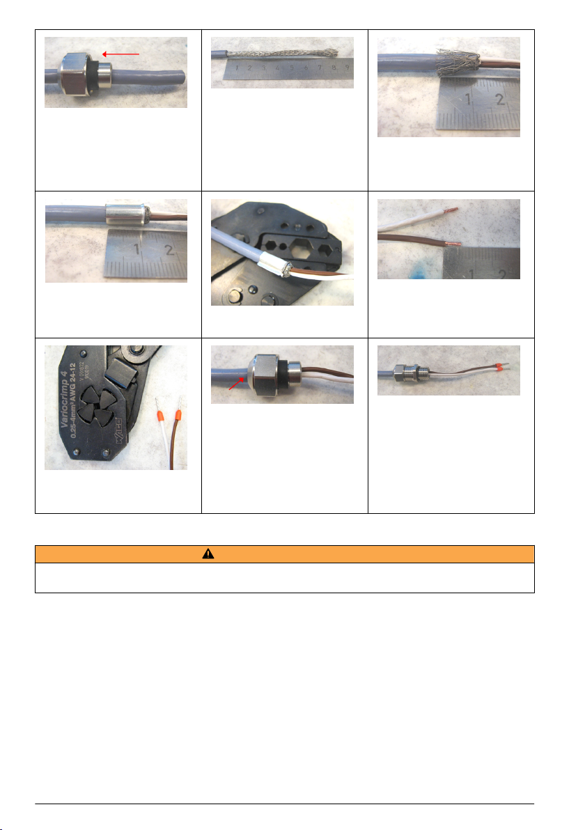
1. Placer l'écrou et le joint
métallique du presse-étoupe sur le
câble blindé.
2. Dénuder 8 cm de la gaine pour
libérer le blindage tressé.
3. Retirer le blindage en laissant
12 mm et libérer les fils internes,
puis enrouler le restant du
blindage par-dessus le câble.
4. Introduire la ferrule de mise à la
masse par-dessus le blindage.
7. Utiliser la pince à sertir pour
fixer les cosses de protection aux
fils.
5. Utiliser la pince pour fixer
solidement la ferrule au câble.
8. Porter le blindage métallique sur
la ferrule et bloquer le tout en
s'assurant que la ferrule n'est pas
exposée à l'extrémité du blindage
côté câble. Porter l'écrou jusqu'à
couvrir le blindage.
6. Retirer 5 mm de l'isolation
externe des fils.
9. Passer la portion filetée du
presse-étoupe sur les fils et la
visser dans l'écrou sur le câble. Le
câble est maintenant prêt à être
branché en suivant la procédure
décrite dans Branchement de
périphériques à la page 86.
Branchement de périphériques
A V E R T I S S E M E N T
Pour se conformer aux normes de sécurité et respecter la conformité CEM de l'analyseur, cette procédure doit
être suivie pour le branchement de tous les périphériques à l'unité électronique de l'analyseur.
86 Français
Page 87
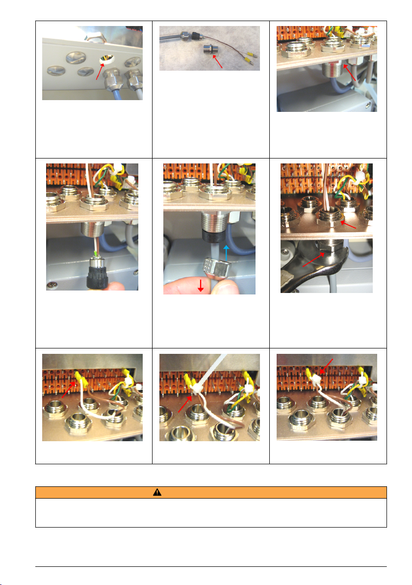
1. Choisir une ouverture libre la
plus proche de la connexion du
câble sur la carte électronique.
Retirer la combinaison vis et écrou
et mettre la vis de côté pour la
réutiliser plus tard.
2. Prendre le câble, dévisser la
partie filetée et le retirer.
3. Visser la partie filetée sur
l'ouverture de l'unité électronique
choisie à l'étape 1 en utilisant
l'écrou retiré à l'étape 1 pour la
fixer en position.
4. Passer le reste du câble à
travers le presse-étoupe.
7. Brancher les fils aux bornes
correctes.
5. Tirer légèrement le câble avec
une main jusqu'à ce que le
blindage interne entre en contact
avec le presse-étoupe. Serrer
l'écrou sur le presse-étoupe avec
l'autre main.
8. Fixer les fils avec un collier pour
câble.
6. Serrer l'écran avec une clé pour
le fixer en position. Il peut être
nécessaire d'utiliser une deuxième
clé pour maintenir l'écrou
supérieur en place.
9. Couper le collier le plus proche
possible des fils.
Branchements de l'électrode
A V E R T I S S E M E N T
Pour se conformer aux normes de sécurité et respecter la conformité CEM de l'analyseur, cette procédure doit
être suivie pour le branchement des électrodes sélective, de référence, combinée et de température à l'unité
électronique de l'analyseur.
Français 87
Page 88
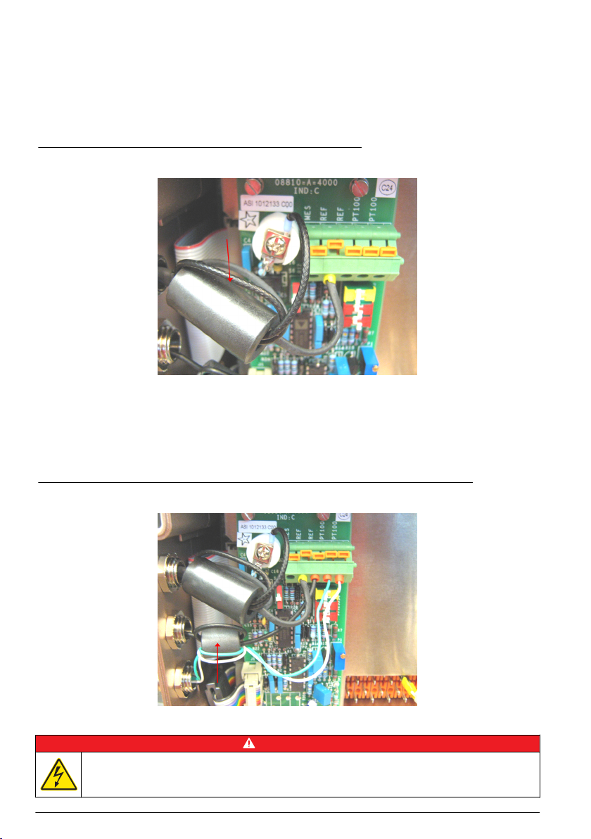
Avant d'être branchés au bornier de la carte de mesure, les câbles de l'électrode doivent passer à
travers les blocs de ferrite pour minimiser le risque d'interférences externes qui pourraient causer
des données de mesure erronées.
Pour l'électrode sélective ou combinée, installer le presse-étoupe et passer le câble dans l'unité
électronique de la même manière que pour tous les autres câbles (comme décrit dans Branchement
de périphériques à la page 86). Lorsque les deux fils (mesure et blindage) sont en place, les passer
à travers le bloc de ferrite. Effectuer une boucle en les passant une deuxième fois à travers la ferrite
avant de les brancher à leurs entrées respectives comme illustré sur la Figure 3.
Figure 3 Branchement de l'électrode sélective ou combinée
Pour l'électrode de référence (sans objet en cas d'électrode combinée) et le capteur de température,
installer les presse-étoupes et passer les câbles dans l'unité électronique de la même manière que
pour tous les autres câbles (comme décrit dans Branchement de périphériques à la page 86).
Lorsque le fil de l'électrode de référence et les deux fils du capteur de température sont en place, les
passer à travers le deuxième bloc de ferrite. Effectuer une boucle en les passant une deuxième fois
à travers la ferrite avant de les brancher à leurs entrées respectives comme illustré sur la Figure 4 (le
capteur de température n'a pas de polarité).
Figure 4 Branchements de l'électrode de référence et du capteur de température
Alimentation électrique
D A N GE R
Risque d'électrocution Débranchez systématiquement l'alimentation de l'appareil avant tout
branchement électrique.
88 Français
Page 89
D A N GE R
Risque d'électrocution Un raccordement à la terre est nécessaire.
D A N GE R
Risque d'incendie et de choc électrique. Assurez-vous d'identifier clairement l'emplacement du
dispositif de déconnexion local pour l'installation du conduit.
A V E R T I S S E M E N T
Risque potentiel d'électrocution. Si cet équipement est utilisé à l'extérieur ou dans des lieux
potentiellement humides, un dispositif de disjoncteur de fuite à la terre doit être utilisé pour le
branchement de l'équipement à sa source d'alimentation secteur.
Dangers multiples. Seul le personnel qualifié doit effectuer les tâches détaillées dans cette section du
document.
Installez l'appareil à un emplacement et dans une position qui ne gênent pas son fonctionnement et permettent
d'accéder facilement à l'interrupteur externe.
L'analyseur est configuré en usine en 110/120 V c.a ou 220 / 240 V c.a. S'assurerAssurez-vous de brancher
l'alimentation correcte à l'analyseur.
A T T EN T I O N
A V I S
A V I S
Raccordez l'équipement conformément aux codes électriques locaux ou nationaux. Respectez
l'ensemble des codes et réglementations relatifs aux câblages. Installez les câbles dans le boîtier de
l'instrument via les passe-câbles fournis.
Utilisez des câbles blindés et raccordés à la terre pour le raccordement à l'alimentation. Les
spécifications du câble d'alimentation sont les suivantes : diamètre compris entre 7 et 9,5 mm, trois
brins, courant nominal de 10 A minimum, surface de section transversale (CSA) minimum comprise
entre 1 mm2 (AWG18) et 2,5 mm2 (AWG14). Pour tous les autres raccordements de signaux, utilisez
les câbles blindés de l'instrument. Utilisez également des câbles blindés et raccordés à la terre pour
le raccordement de signaux.
Remarque : L'équipement prévu pour le raccordement permanent à l'alimentation doit prévoir le raccordement à un
système de câblage conformément à ANSI/NFPA 70, NEC, avec CSA C22.1.
Assurez-vous qu'un disjoncteur 2 pôles d'une capacité minimum de court-circuit de 20 A est installé
sur le câble électrique. Installez un dispositif de coupure local pour l'instrument à moins de 3 m (10
pi) de cet instrument. Placez une étiquette sur le dispositif de coupure signalant qu'il s'agit du
dispositif de coupure principal pour l'instrument.
Lorsque le câblage du système est complété, effectuez les étapes suivantes pour alimenter le
système :
1. Ouvrir le boîtier d'alimentation (nº 12 sur la Figure 1 à la page 82).
2. Passer le câble d'alimentation à travers le presse-étoupe et brancher respectivement les fils de
terre, neutre et phase aux bornes 1, 2 et 3 comme indiqué sur la Figure 5.
Français
89
Page 90
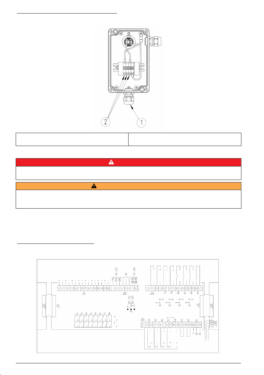
Figure 5 Boîtier d'alimentation électrique
1 Presse-étoupe d'alimentation secteur 2 Bornes de branchement (1 = terre, 2 = neutre, 3 =
phase)
Branchements des entrées/sorties
D A N GE R
Risque d'électrocution. Toujours s'assurer que l'analyseur est hors tension et que l'alimentation est débranchée
avant d'effectuer tous les branchements dans cette section.
A V E R T I S S E M E N T
Pour se conformer aux normes de sécurité et respecter la conformité CEM de l'analyseur, suivre les procédures
définies dans Procédures de câblage et préparation du câble à la page 84 pour tous les branchements à l'unité
électronique de l'analyseur.
L'unité électronique (nº 11 sur la Figure 1 à la page 82) doit être ouverte par l'arrière pour effectuer
ces branchements. Dévisser les quatre vis retenant le panneau arrière de l'unité et le basculer
doucement de gauche à droite pour l'ouvrir. Consulter Figure 6 pour les emplacements des bornes et
les tableaux suivants pour les fonctions.
Remarque : Le schéma des connecteurs de borne est également situé à l'arrière de l'unité électronique.
Figure 6 Connecteurs de borne
90 Français
Page 91
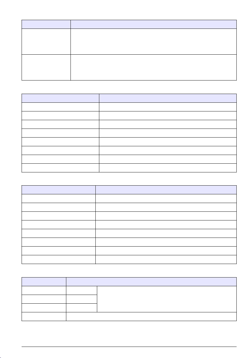
Tableau 1 Carte microprocesseur
Borne Désignation
Configurations de relais K5 - K8
X1 - X4
X5
• 2-3 : Relais à contact sec
• 1-2 et 3-4 : 24 VCC
Interface série
• 1-2 : RS 232
• 2-3 : RS 485
Tableau 2 Détecteur de niveau et commandes externes (J1 - J8)
Borne Utilisation
J1 Départ/veille
J2 Échantillon externe
J3 Non utilisées
J 4 Solution de conditionnement
J5 Solution de titrage
J6 Solution d’étalonnage
J7 Nettoyage chimique
J8 Echantillon
Tableau 3 Sorties analogiques (J9)
Borne Utilisation
1-2 Sortie analogique 1
3-4 Sortie analogique 2
5-6 Sortie analogique 3
7-8 Sortie analogique 4
9-10 Sortie analogique 5
11-12 Sortie analogique 6
13-14 Sortie analogique 7
15-16 Sortie analogique 8
Tableau 4 Interface série (J10)
Borne Utilisation
1 TXD
RS 232 configuré par l'utilisateur avec X5 2 RXD
3 TERRE
4, 5, 6, 7, 8 Non utilisées
Français 91
Page 92
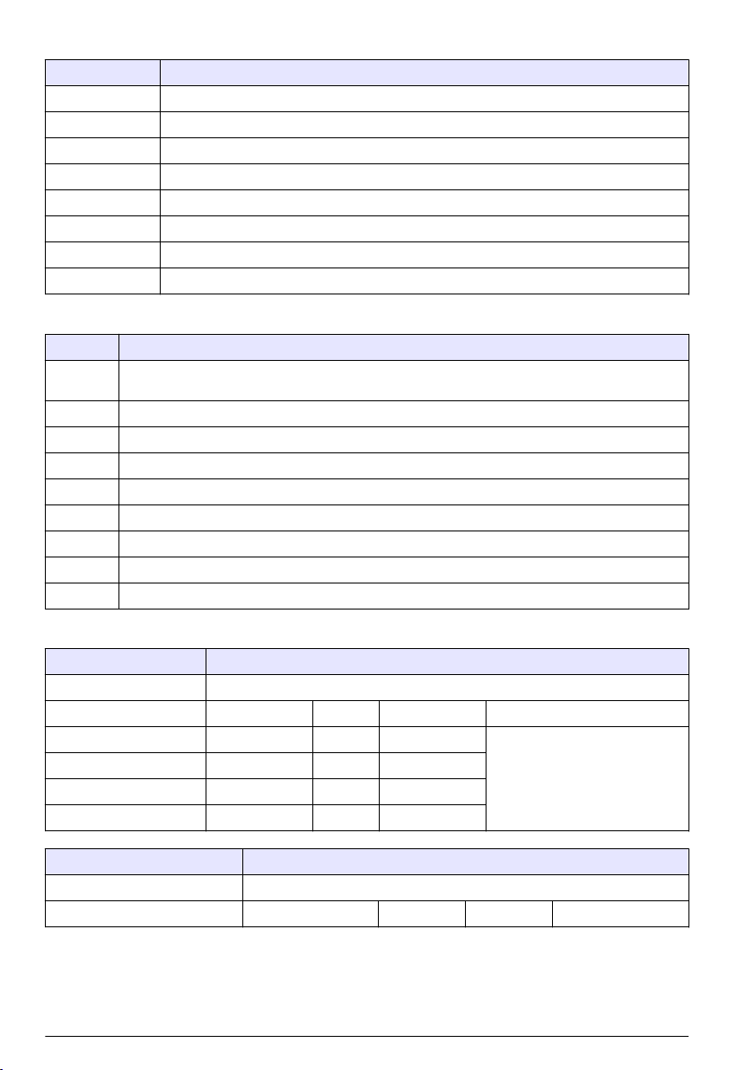
Tableau 5 Accessoires 1 (J13)
Borne Utilisation
1-11 Système de chauffage
2-3 Mélangeur
4-5 Robinet de rinçage
6-7 Robinet de rinçage
8-9 Robinet d'échantillon
12-13 Alarme 2
14-15 Alarme 1
16-17-18 Alarme système (16-17 pour NO ou 16-18 pour NC)
Tableau 6 Accessoires 2 (J14)
Borne Utilisation
1-11 (8-10) Étalonnage automatique ou pompe d'échantillon externe (brancher 8 et 10 et placer le cavalier
2-3 Non utilisées
4-5 Robinet de nettoyage chimique
6-7 Robinet de dilution
8-9 Non utilisées
10-11 Pompe 4
12-13 Pompe 3 (X3 placé sur 1-2 et 3-4)
14-15 Pompe 2 (X2 placé sur 1-2 et 3-4)
16-17 Pompe 1 (X1 placé sur 1-2 et 3-4)/étalonnage automatique
X4 sur 2-3)
Tableau 7 Fonctions pompe 1 - 4
CAL AUTO YES ou MANUAL YES
Cavalier X4 X4 placé sur 2-3 et un pont entre 8 et 10 de J14
Pompe 1 Pompe 2 Pompe 3 Pompe 4
1 solution titrée/1 cond. Solution titrée 1 Cond 1
1 solution titrée/2 cond. Solution titrée 1 Cond 1 Cond 2
2 solutions titrées/1 cond. Solution titrée 1 Cond 1 Solution titrée 2
2 solutions titrées/2 cond. Solution titrée 1 Cond 1 Solution titrée 2
CAL AUTO NO et MANUAL NO
Cavalier X4 X4 placé entre 1-2 et 3-4 et aucun pont entre 8 et 10 de J14
Pompe 1 Pompe 2 Pompe 3 Pompe 4
CAL AUTO ou OTHER SAMPLE
92 Français
Page 93
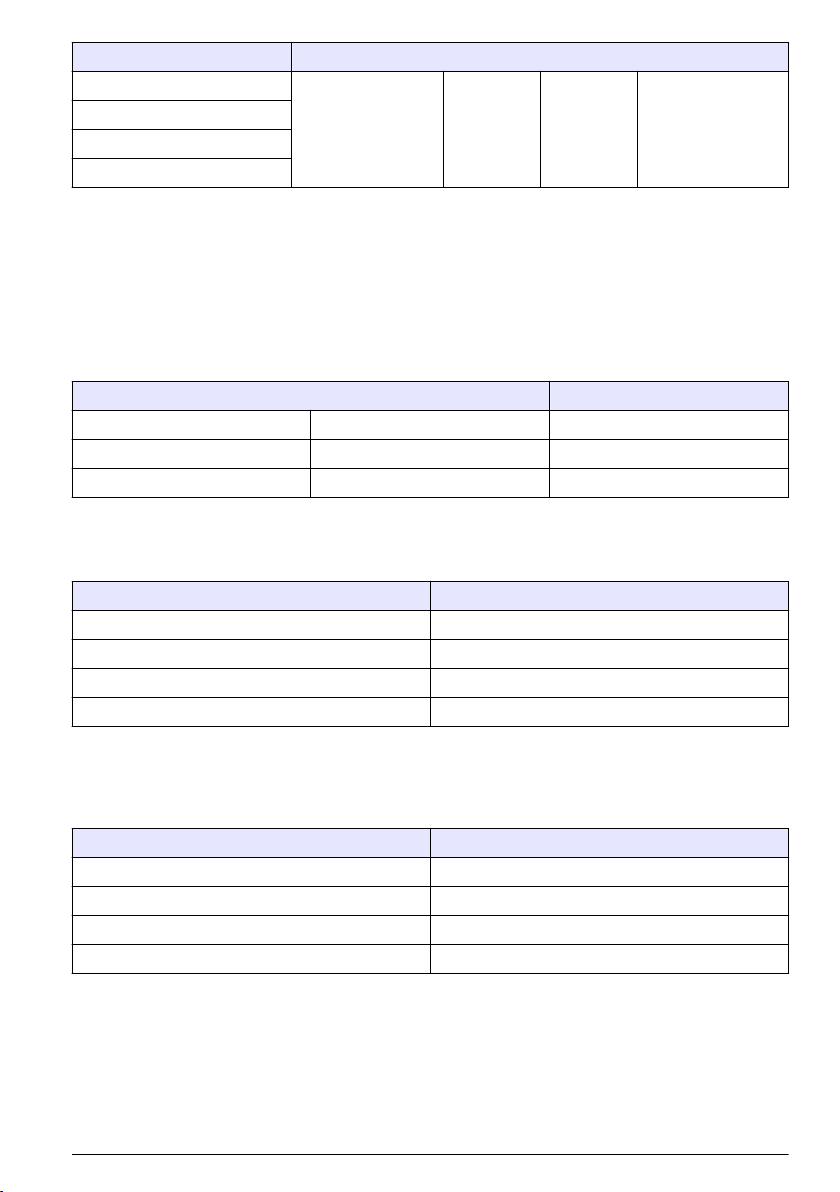
CAL AUTO NO et MANUAL NO
1 solution titrée/1 cond.
1 solution titrée/2 cond.
2 solutions titrées/1 cond.
2 solutions titrées/2 cond.
Solution titrée 1 Cond 1 Cond 2 Solution titrée 2
Alarmes
Consulter également Figure 6 à la page 90 et Tableau 5 à la page 92. Les relais de seuil d'alarme
(K2 et K3) sont configurés sur normalement ouvert (NO). Le relais d'alarme système (K1) peut être
configuré sur normalement ouvert (bornes 16 et 17) ou normalement fermé (bornes 16 et 18).
Sorties analogiques
Consulter également Figure 6 à la page 90 et Tableau 3 à la page 91. Les sorties analogiques
0-20 mA ou 4-20 mA sont isolées galvaniquement. Le tableau suivant montre l'assignation des
différentes sorties :
Analyseur
I out 1 Borne 1-2 de J9 Canal de mesure
I out 2 Borne 3-4 de J9 Potentiel de mesure
I out 3 Borne 5-6 de J9 Non utilisées
Détecteur de niveau d’échantillon
Consulter également Figure 6 à la page 90 et Tableau 2 à la page 91. Le réacteur est équipé d'un
détecteur de niveau d'échantillon. Brancher la connexion à J8 comme suit :
Numéro de borne J8 Couleur
1 Marron
2 Vert
3 Jaune
4 Blanc
Détecteur de niveau de réactif
Consulter également Figure 6 à la page 90 et Tableau 2 à la page 91. Chaque bouteille de réactif est
équipée d'un détecteur de niveau. Pour chaque réactif, brancher les connexions à J4, J5, J6 et
J7 comme suit :
Numéro de borne J4, J5, J6 et J7 Couleur
1 Non utilisées
2 Non utilisées
3 Marron
4 Blanc
Connexion RS232
Consulter également Figure 6 à la page 90 et Tableau 4 à la page 91. Brancher la connexion à
J10 comme suit :
Français
93
Page 94
Numéro de borne J10 Fiche DB9 Fiche DB25
1 (TXD) RXD : 2 RXD : 2
2 (RXD TXD : 3 TXD : 3
3 (GND) COM : 5 COM : 7
La configuration du 8810 est :
• Débit : 9600 bauds
• Données : 8 bits
• Bit d'arrêt : 2
• Parité : aucune
Lors du démarrage, l'analyseur envoie le nom et la version du logiciel :
• ANALYZER 8810 : 00 : 00 : 00 :
• pH X.XX : 00 : 00 : 00 :
En mode mesure, l'analyseur envoie les données suivantes :
• Titration HH : MM : SS
• M1 XXXXEXX XX.X°C XXX pour le premier point final
• M2 XXXXEXX XX.X°C XXX pour le deuxième point final
• M3 XXXXEXX XX.X°C XXX pour le différentiel entre les deux points finaux
Où :
• MX XXXXEXX = valeur de mesure de concentration
• XX.X°C = température
• XXX = valeur du potentiel
En mode tracé de graphique, l'analyseur envoie les données suivantes :
• Plotting HH : MM : SS
• P : XX.X°C XXX
Où :
• XX.X°C = température
• XXX = valeur de pH
Si nécessaire, l'analyseur envoie également les messages suivants avec un horodatage (HH: MM :
SS) :
ACTIONS
Cleaning Nettoyage chimique
Stopped Analyseur arrêté
Fix-time Temps entre deux cycles
Standby Analyseur en veille
AUTO SYS CAL Étalonnage automatique
PROCESS SYS CAL Étalonnage de processus
MANUAL SYS CAL Étalonnage manuel
94 Français
Page 95
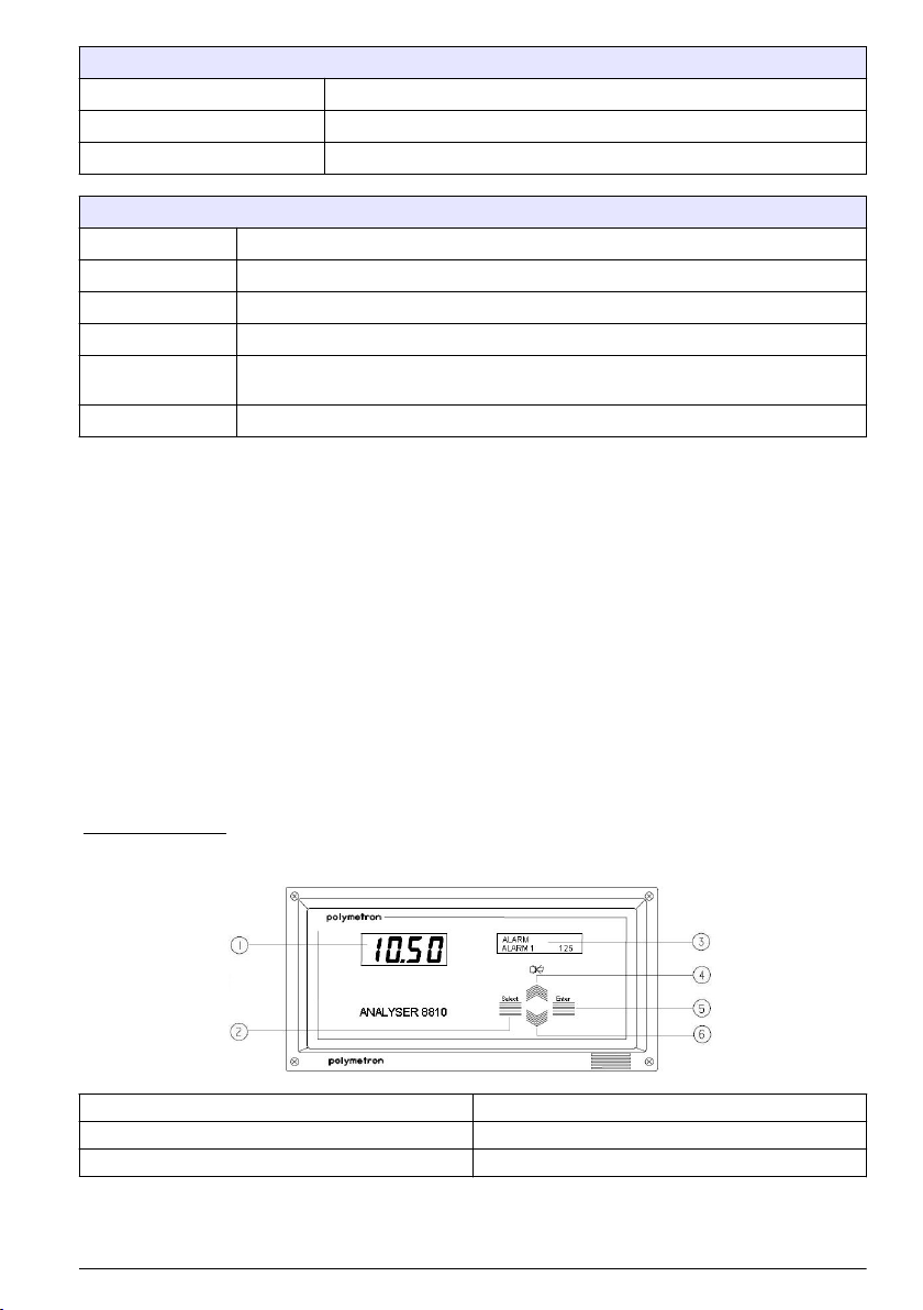
ERREURS SYSTÈME
LEVEL SAMPLE Échantillon absent de la cellule de mesure
OVER TITR TIME Temps de titrage trop long
ERROR CALIB Erreur d'étalonnage automatique
AVERTISSEMENTS
LEVEL REAGENT Réactif de titrage absent
LEVEL COND Réactif de conditionnement absent
LEVEL CALIB Solution d'étalonnage absente
LEVEL CLEANING Solution de nettoyage absente
RETURN PROCESS Après une mesure d'échantillon externe, ce message indique un retour à la mesure de
SLOPE CALIB 1/2 Erreur d'étalonnage automatique
processus
Accessoires supplémentaires
Tout accessoire ayant été acheté, mais qui n'a pas été installé en usine, peut maintenant être
installé. Les instructions pour l'installation et le câblage sont fournies dans le manuel de l'utilisateur
complet.Lorsque tout a été installé, effectuer les contrôles suivants dans la chambre de mesure:
• Rien ne doit toucher l'agitateur
• La partie supérieure du tube de trop-plein se trouve à environ 2 cm au-dessus du siphon
• Le détecteur de niveau se trouve à environ 1 cm au-dessous du bas de l'orifice du siphon
• Si elle n'est pas branchée, brancher l'électrode de mesure au câble plus épais et l'électrode de
référence au câble plus fin.
Interface utilisateur
Description de la façade
L'interface est composée d'un clavier à 4 touches, d'un écran numérique à 4 chiffres et d'un écran
alphanumérique de 2 lignes de 16 caractères.
Figure 7 Façade
1 Écran numérique 4 Touche de défilement vers le haut
2 Touche de sélection 5 Touche Entrée
3 Écran alphanumérique 6 Touche de défilement vers le bas
Français 95
Page 96

Touches de fonction
• Enter : appelle les fonctions ou confirme les paramètres.
• Select : sélectionne les options du menu, ajuste les paramètres, quitte les sous-menus et bascule
entre le mode commande et utilisation.
• Défilement vers le bas : ajuste les variables, fait défiler les écrans en mode utilisation et les sous-
menus en mode commande.
• Défilement vers le haut : identique au défilement vers le bas, mais dans l'ordre inverse ; annule
également l'alarme système.
Modes de l'analyseur
L'analyseur fonctionne en mode Operating (Utilisation) ou en mode Command (Commande). En
mode Operating, l'analyseur effectue des actions standard comme la mesure, l'étalonnage, etc. Un
nom limité de paramètres peut également être affiché à l'aide des touches de défilement. En mode
Command, l'analyseur peut être programmé, les paramètres peuvent être affichés et les fonctions
de l'analyseur peuvent être testées. Par défaut, l'analyseur est en mode Command lors de la
première mise sous tension.
Pour passer en mode Operating à partir du mode Command, sélectionner START (DÉMARRAGE)
dans le MAIN MENU (MENU PRINCIPAL).
Pour passer en mode Command à partir du mode Operating, appuyer sur Select pour afficher la
commande STOP, puis
• pour afficher uniquement les paramètres actuellement définis, à partir de la commande STOP
utiliser les touches de défilement pour sélectionner READING (LECTURE) et appuyer sur Enter
pendant 3 secondes environ.
• pour programmer l'analyseur ou tester les fonctions de l'analyseur, à partir de la commande STOP
appuyer sur Enter, puis à nouveau sur Enter pour confirmer. Utiliser ensuite les touches de
défilement pour sélectionner PROGRAMMING (PROGRAMMATION) et appuyer sur Enter
pendant 3 secondes environ.
Indicateurs
Écran numérique : cet écran affiche les mesures de concentration (par défaut), potentiel ou
température.
Écran alphanumérique : cet écran affiche les messages d'état et de programmation. Les messages
diffèrent selon le mode :
• Mode Utilisation : la ligne supérieure indique les unités, le type de mesure et toute alarme active.
La ligne inférieure indique l'état de l'analyseur (par ex. étalonnage, titrage, etc.).
• Mode Commande : la ligne supérieure indique le menu principal. La ligne inférieure indique les
sous-menus et les paramètres de données.
Aperçu du menu
MENU PRINCIPAL
Le menu principal permet l'accès aux fonctions suivantes :
• STOP - L'appui sur Enter entraîne l'arrêt immédiat du processus de mesure
• START - L'appui sur Enter lance le processus de mesure
• STAND-BY - L'appui sur Enter place l'analyseur en veille
• PROGRAMMING - Programmer l'analyseur (mode Command uniquement)
• READING - Afficher les paramètres (mode Operating uniquement)
En mode PROGRAMMING ou READING, les options suivantes peuvent être sélectionnées à l'aide
des touches de défilement :
• MEASUREMENT - Paramètres de titrage
96
Français
Page 97

• CALIBRATION - Étalonner l'analyseur
• ANALOG-OUT - Paramètres de sortie analogique
• ALARM - Paramètres de limite d'alarme
• SEQUENCE - Mode de mesure
• SERVICE - Contrôler du fonctionnement de l'analyseur et des accessoires
• CLEANING - Paramètres de nettoyage chimique
• SAMPLE COND. - Paramètres de conditionnement d'échantillon
• CAL PARAMETER - Afficher les détails de l'étalonnage primaire et du dernier étalonnage
• TIMING - Paramètres de cycle de titrage
• PM XXXX - Configuration du système (disponible uniquement en mode PROGRAMMING et exige
un mot de passe valide)
Remarque : Certaines des options ci-dessus ne sont disponibles que si l'accessoire correspondant a été installé.
Configuration du système (option PM XXXX)
Consulter également les documents de Procédure d'installation fournis avec l'analyseur pour
obtenir des informations spécifiques à l'application.
1. Sélectionner PM XXXX avec les touches de défilement et appuyer sur Enter (Entrée). À l'aide de
la touche Select (Sélection) pour passer d'un caractère à l'autre, entrer le mot de passe et
appuyer sur Enter (Entrée).
Option Désignation
APPLICATION Sélectionner l'application dans la liste.
UNIT Sélectionner l'unité de concentration dans la liste. La sélection de USER (UTILISATEUR)
Adjust ADC Cette option est réservée aux techniciens de service HACH LANGE.
Adjust Iout Sélectionner le type de sortie analogique (0-20 mA ou 4-20 mA). Placer un multimètre en
OPTION Dans la liste, sélectionner YES (OUI) pour les options installées/requises et NO (NON) pour
permet de définir sa propre valeur et nécessite une description de 5 caractères.
série avec la sortie analogique et effectuer de petits ajustements du signal si nécessaire.
les options qui ne sont pas installées/requises.
Remarque : Certaines options exigent l'installation de matériel supplémentaire (par ex.
AUTO SYS CAL, CLEANING, HEATING, etc.). Pour un fonctionnement correct de
l'analyseur, toutes les installations de matériel doivent être effectuées avant la mise en
service.
Paramètres de titrage (option MEASUREMENT)
Pour les applications ACID et BASE, un seul jeu de paramètres est requis. Pour les autres
applications, deux jeux de paramètres sont requis.
1. Sélectionner MEASURE (MESURE) avec les touches de défilement et appuyer sur Enter
(Entrée).
Option Désignation
PRE-ENDPT1/2 Saisir la valeur précédant le point final.
ENDPT1/2 Saisir la valeur du point final.
Étalonnage (option CALIBRATION)
Étalonnage en mode LECTURE
L'option CALIBRATION (ÉTALONNAGE) est disponible pour afficher les paramètres d'étalonnage.
Faire défiler la liste des paramètres lorsqu'ils s'affichent.
Français
97
Page 98

Étalonnage en mode PROGRAMMATION
Trois options sont disponibles :
• PRIMARY CALIBRATION
• SYSTEM CALIBRATION
• ELECTRODE CALIBRATION
Étalonnage PRIMAIRE ou SYSTÈME
Un étalonnage primaire est effectué en usine et utilisé comme référence pour tous les autres
étalonnages. En général, il ne doit pas être renouvelé à moins que des modifications importantes
aient été effectuées au système (par ex. remplacement d'électrode).
La procédure pour l'étalonnage PRIMAIRE ou SYSTÈME est la même.
1. Dans le menu CALIBRATION (ÉTALONNAGE), sélectionner PRIMARY CAL (ÉTALONNAGE
PRIMAIRE) ou SYSTEM CAL (ÉTALONNAGE SYSTÈME) avec les touches de défilement et
appuyer sur Enter (Entrée).
Option Désignation
MANUAL SYS CAL Cet étalonnage exige une ou plusieurs solutions d'étalonnage préparées en
PROCESS SYS CAL Cet étalonnage utilise la solution du processus, avec une concentration connue,
AUTO SYS CAL Disponible uniquement si cette option a été installée.
Étalonnage manuel
1. Sélectionner MANUAL SYS CAL (ÉTALONNAGE SYSTÈME MANUEL) et appuyer sur Enter
(Entrée).
2. FILL CAL SOL. (ERREUR ÉTALONNAGE) s'affiche. Verser la solution d'étalonnage dans la
chambre de mesure et appuyer sur Enter (Entrée).
3. CONC SOL: XXXXX s'affiche. Entrer la concentration sous forme d'un numéro de cinq chiffres
sans point décimal ou sous forme de numéro de quatre chiffres avec point décimal. Appuyez sur
Enter (Entrée) pour confirmer.
4. Si l'option 2 INDEP PTS ou TWO REAGENTS a été sélectionnée, la concentration du deuxième
point est nécessaire. Saisir la concentration de la deuxième solution et appuyer sur Enter
(Entrée).
laboratoire avec une concentration connue.
comme solution d'étalonnage.
Étalonnage de processus
1. Sélectionner PROCESS SYS CAL (ÉTALONNAGE SYSTÈME PROCESSUS) et appuyer sur
Enter (Entrée).
2. CONC SOL: XXXXX s'affiche. Entrer la concentration sous forme d'un numéro de cinq chiffres
sans point décimal ou sous forme de numéro de quatre chiffres avec point décimal. Appuyez sur
Enter (Entrée) pour confirmer.
3. Si l'option 2 INDEP PTS ou TWO REAGENTS a été sélectionnée, la concentration du deuxième
point est nécessaire. Saisir la concentration de la deuxième solution et appuyer sur Enter
(Entrée).
Étalonnage automatique
Disponible uniquement si cette option est installée sur l’analyseur. Elle permet l'étalonnage
automatique à intervalles prédéfinis à l'aide d'une solution d'étalonnage de concentration connue.
Remarque : Lors de la première sélection de cette option, sélectionner NO pour IMMEDIATE à l'étape 3 afin de
saisir les paramètres supplémentaires requis.
98
Français
Page 99

1. Contrôler le contenu de la bouteille de solution d'étalonnage. Un étalonnage utilise 250 à 300 ml
de solution d'étalonnage, ainsi la capacité d'une bouteille standard permettra 30 à
40 étalonnages.
2. Sélectionner AUTO SYS CAL (ÉTALONNAGE SYSTÈME AUTOMATIQUE) et appuyer sur
Enter (Entrée). IMMEDIATE s'affiche. Sélectionner YES (OUI) ou NO (NON), suivi de Enter
(Entrée). Si YES (OUI) est sélectionné, un étalonnage automatique démarrera immédiatement.
Aucune autre saisie n'est requise.
3. Si NO est sélectionné, saisir la FRÉQUENCE des étalonnages. Il s'agit du nombre de titrages
entre chaque étalonnage automatique.
4. CONC SOL: XXXXX s'affiche. Entrer la concentration sous forme d'un numéro de cinq chiffres
sans point décimal ou sous forme de numéro de quatre chiffres avec point décimal. Appuyez sur
Enter (Entrée) pour confirmer.
5. Si l'option 2 INDEP PTS ou TWO REAGENTS a été sélectionnée, la concentration du deuxième
point est nécessaire. Saisir la concentration de la deuxième solution et appuyer sur Enter
(Entrée).
6. INJ. TIME s'affiche. Entrer le temps d'injection de la solution d'étalonnage en secondes et
confirmer avec Enter (Entrée).
Étalonnage de l'ÉLECTRODE
L'étalonnage de l'électrode nécessite deux solutions tampon de concentration connue pour effectuer
un étalonnage en 2 points. Les solutions tampon doivent avoir des concentrations de pH différentes
comprises entre 1 et 9 ou proches des valeurs de l'application. La solution tampon 1 doit avoir la
valeur de pH la plus basse et la solution tampon 2 la valeur la plus élevée.
1. Dans le menu CALIBRATION (ÉTALONNAGE), sélectionner ELECTRODE CAL
(ÉTALONNAGE ÉLECTRODE) avec les touches de défilement et appuyer sur Enter (Entrée).
Option Désignation
2 POINTS Appuyer sur Enter (Entrée) pour confirmer un étalonnage à 2 points.
FILL BUFFER 1 (REMPLIR
TAMPON 1)
BUFFER 1: XXXXX Saisir la valeur de pH de la première solution tampon et appuyer sur Enter
FILL BUFFER 2 (REMPLIR
TAMPON 2)
BUFFER 2: XXXXX Saisir la valeur de pH de la deuxième solution tampon et appuyer sur Enter
Remplir la chambre de mesure avec la première solution tampon et
appuyer sur Enter (Entrée).
(Entrée).
Remplir la chambre de mesure avec la deuxième solution tampon et
appuyer sur Enter (Entrée).
(Entrée).
Résultats d’étalonnage
Dans PRIMARY CAL (ÉTALONNAGE PRIMAIRE), l'étalonnage est toujours considéré correct et
sera utilisé comme référence pour les autres étalonnages. La pente est considérée à 100 %.
Pour les autres étalonnages, les nouvelles pentes sont comparées aux valeurs de l'étalonnage
primaire. Si les nouvelles valeurs de pente sont comprises entre 70 et 130 % des valeurs actuelles,
elles seront considérées valides et utilisées pour tous les futurs calculs de mesure.
Si les nouvelles valeurs de pente sont comprises entre 50 et 70 % ou entre 130 et 150 % des valeurs
actuelles, il est nécessaire de CONFIRMER les nouvelles valeurs. Sélectionner YES (OUI) ou NO
(NON), puis appuyer sur Enter (Entrée). Si YES (OUI) est sélectionné, les nouvelles valeurs sont
utilisées pour tous les futurs calculs de mesure. Si NO (NON) est sélectionné (ou si les nouvelles
valeurs de pente sont <50 % ou >150 % des valeurs actuelles), le message ERROR CALIB
(ERREUR ÉTALONNAGE) s'affiche. Appuyez sur Enter (Entrée) pour continuer.
CAL ERROR (ERREUR ÉTALONNAGE) indique une erreur d'étalonnage. Sélectionner RETRY
(RÉESSAYER) pour répéter l'étalonnage ou ABORT (ANNULER) pour annuler l'étalonnage.
Français
99
Page 100
En étalonnage automatique, l'instrument ne demande aucune confirmation. Toutefois, si la déviation
de la pente est >50 % ou >150 % des valeurs actuelles, un message d'avertissement SLOPE
CALIB ! (ÉTALONNAGE PENTE) s'affiche sur l'écran.
Sorties analogiques (option ANALOG-OUT)
L'analyseur possède deux sorties analogiques qui sont assignée en fonction de l'application :
Application Sortie analogique 1 Sortie analogique 2
ACID Concentration d'acide pH lors du démarrage d'un titrage
BASE Concentration de base pH lors du démarrage d'un titrage
FREE/TOTAL ACID FREE TOTAL
FREE/TOTAL BASE FREE TOTAL
2p-m p 2p-m
x(p-m) m x(p-m)
x(m-p) p x(m-p)
1. Sélectionner ANALOG-OUT (SORTIE ANALOGIQUE) avec les touches de défilement et appuyer
sur Enter (Entrée).
Option Désignation
START I1/2 Saisir la valeur qui correspond à la sortie de courant 0/4 mA.
END I1/2 Saisir la valeur qui correspond à la sortie de courant 20 mA.
Conc Tester la sortie en envoyant le courant correspondant à la dernière valeur mesurée.
Full Tester la sortie en envoyant le courant maximum de 20 mA.
Zero Tester la sortie en envoyant le courant minimum de 0 ou 4 mA selon la configuration de
l'analyseur.
Remarque : Il n'est possible de quitter ce menu que lorsque l'option Conc est affichée.
Définir les alarmes et les seuils (option ALARM)
L'analyseur possède trois alarmes qui sont assignées en fonction de la définition de WARNING/R1
(AVERTISSEMENT/R1) :
WARNING/R1 réglé sur NO (NON) WARNING/R1 réglé sur YES (OUI)
Alarme système Alarmes système et avertissement Alarme système uniquement
Alarme 1 Alarme 1 Alarme d'avertissement
Alarme 2 Alarme 2 Alarme 1 et 2
1. Sélectionner ALARM (ALARME) avec les touches de défilement et appuyer sur Enter (Entrée).
Option Désignation
SYS.ALARM ON/OFF Active ou désactive l’alarme système.
WARNING/R1 YES/NO Définit l'assignation de l'alarme (voir tableau ci-dessus).
ALARM 1/2 ON/OFF Active ou désactive les alarmes 1 et 2.
ALARM 1/2 XXX/XXX Si activée, définit que mesure déclenche l'alarme (spécifique à l'application).
100 Français
 Loading...