

Page 1

DOC026.97.80331
HIAC PODS
08/2013, Edition 1
Manuel d'utilisation de base
Manual básico del usuario
Manual Básico do Usuário
Basic User Manual
Page 2

English...................................................................................................................................................................................................3
Français..............................................................................................................................................................................................21
Español...............................................................................................................................................................................................42
Português..........................................................................................................................................................................................63
2
Page 3

Table of contents
Additional information on page 3
Specifications on page 3
General information on page 4
Installation on page 7
Startup on page 8
User interface and navigation on page 9
Operation on page 12
Maintenance on page 16
Troubleshooting on page 19
Additional information
Additional information is available on the manufacturer's website.
Specifications
Specifications are subject to change without notice.
Specification Details
Dimensions (D x W x H) 18.5 x 33.0 x 40.0 cm (7.3 x 12.5 x 15.7 in.)
Weight 9.3 kg (20.5 lb)
Number of channels 8
Size channels ISO-MTD 4, 4.6, 6, 9.8, 14, 21.2, 38, 68 μm
ACFTD ~1, 2, 5, 10, 25, 50, 100 μm
Flow rate 15 to 50 ml/min (automatic/manual)
Light source Class 3B laser, 810-852 nm, 50 mW maximum
Calibration ISO MTD (based on ISO 11171)
Full ISO 11171 Optional
Counting efficiency JIS B9925:1997
Concentration limit 20,000 particles per ml @ 5% coincidence loss
Sample volume 3 runs (averaged) of 5, 10 or 20 ml/run
(per ISO 11171)
30,000 particles/ml @ 10% coincidence
(programmable)
Specification Details
Fluid temperature range 0 to 90 °C at 25 °C ambient (32 to 194 °F at
Measured fluid temperature 0 to 100 °C, ±0.5 °C (32 to 212 °F, ±0.9 °F)
Viscosity range 10 to 424 cSt (59 to 2000 SUS)
Wetted materials Aluminum, stainless steel, sapphire, PTFE and
Cleanliness classification ISO 4406-1991, ISO 4406-1999, NAS 1638, MIL-
Data storage 500 sample records
Input/output serial
communication
Altitude 2000 m (6561.7 feet)
Certifications CE
Bottle operation
Purge volume 15 to 30 ml (automatic/manual)
Cartridge CO2, replaceable, rechargeable
Operating time 60 samples (120 ml sample bottle)
Shop air 620 to 758 kPa (90 to 100 psi; 6.2 to 7.6 bar)
Fluid pressure 40 to 5000 psi (2.75 to 345 bar)
Power
DC input 24 VDC, 2 A maximum
AC adapter Universal 100–240 VAC, 50–60 Hz, 60 W
Rechargeable battery Nickel-metal hydride
77 °F)
For viscosity measurement, viscosity range is
10 to 424 cSt ±20% at value.
®
Aflas
STD-1246C, SAE AS 4059, NAVAIR 01-1A-1
RS232
Programmable
Programmable, hold time and sample number
clean, dry
English 3
Page 4

Specification Details
Operating time 100 samples or 4 hours continuous
Recharge time 2.5 hours
Environment
Operating environment 0 to 55 °C (32 to 131 °F), 5 to 95% relative
Storage -40 to 70 °C (-40 to 158 °F), up to 98% relative
humidity, non-condensing
humidity, non-condensing
General information
In no event will the manufacturer be liable for direct, indirect, special,
incidental or consequential damages resulting from any defect or
omission in this manual. The manufacturer reserves the right to make
changes in this manual and the products it describes at any time, without
notice or obligation. Revised editions are found on the manufacturer’s
website.
Safety information
N O T I C E
The manufacturer is not responsible for any damages due to misapplication or
misuse of this product including, without limitation, direct, incidental and
consequential damages, and disclaims such damages to the full extent permitted
under applicable law. The user is solely responsible to identify critical application
risks and install appropriate mechanisms to protect processes during a possible
equipment malfunction.
Please read this entire manual before unpacking, setting up or operating
this equipment. Pay attention to all danger and caution statements.
Failure to do so could result in serious injury to the operator or damage
to the equipment.
Make sure that the protection provided by this equipment is not impaired.
Do not use or install this equipment in any manner other than that
specified in this manual.
Use of hazard information
D A N G E R
Indicates a potentially or imminently hazardous situation which, if not avoided, will
result in death or serious injury.
Indicates a potentially or imminently hazardous situation which, if not avoided,
could result in death or serious injury.
Indicates a potentially hazardous situation that may result in minor or moderate
injury.
Indicates a situation which, if not avoided, may cause damage to the instrument.
Information that requires special emphasis.
W A R N I N G
C A U T I O N
N O T I C E
Precautionary labels
Read all labels and tags attached to the instrument. Personal injury or
damage to the instrument could occur if not observed. A symbol, if noted
on the instrument, will be included with a danger or caution statement in
the manual.
4 English
Page 5

This symbol, if noted on the instrument, references the instruction
manual for operation and/or safety information.
Electrical equipment marked with this symbol may not be disposed of
in European public disposal systems after 12 August of 2005. In
conformity with European local and national regulations (EU Directive
2002/96/EC), European electrical equipment users must now return
old or end-of-life equipment to the Producer for disposal at no charge
to the user.
Note: For return for recycling, please contact the equipment producer or supplier
for instructions on how to return end-of-life equipment, producer-supplied
electrical accessories, and all auxiliary items for proper disposal.
This symbol indicates the need for protective eye wear.
Class 1 laser product
This instrument is classified as a Class 1 laser product. This product
complies with IEC/EN 60825-1:2007 and 21 CFR 1040.10 except for
deviations pursuant to Laser Notice No. 50, dated June 24, 2007.
US FDA Accession number 9912262-006. This product contains a
810-852 nm, 50 mW, class 3B laser that is not user-serviceable.
Certification
Canadian Radio Interference-Causing Equipment Regulation,
IECS-003, Class A:
Supporting test records reside with the manufacturer.
This Class A digital apparatus meets all requirements of the Canadian
Interference-Causing Equipment Regulations.
Cet appareil numérique de classe A répond à toutes les exigences de la
réglementation canadienne sur les équipements provoquant des
interférences.
FCC Part 15, Class "A" Limits
Supporting test records reside with the manufacturer. The device
complies with Part 15 of the FCC Rules. Operation is subject to the
following conditions:
1. The equipment may not cause harmful interference.
2. The equipment must accept any interference received, including
interference that may cause undesired operation.
Changes or modifications to this equipment not expressly approved by
the party responsible for compliance could void the user's authority to
operate the equipment. This equipment has been tested and found to
comply with the limits for a Class A digital device, pursuant to Part 15 of
the FCC rules. These limits are designed to provide reasonable
protection against harmful interference when the equipment is operated
in a commercial environment. This equipment generates, uses and can
radiate radio frequency energy and, if not installed and used in
accordance with the instruction manual, may cause harmful interference
to radio communications. Operation of this equipment in a residential
area is likely to cause harmful interference, in which case the user will be
required to correct the interference at their expense. The following
techniques can be used to reduce interference problems:
1. Disconnect the equipment from its power source to verify that it is or
is not the source of the interference.
2. If the equipment is connected to the same outlet as the device
experiencing interference, connect the equipment to a different
outlet.
3. Move the equipment away from the device receiving the interference.
4. Reposition the receiving antenna for the device receiving the
interference.
5. Try combinations of the above.
Product overview
The Portable Oil Diagnostic System (PODS) is used to measure, keep
and report oil contamination that is important for reliable hydraulic
system operation. The instrument takes an analysis of pressurized fluids
and lubricants in online or bottle sampling modes without disruption of
machine operations.
English
5
Page 6

The instrument is compatible with petroleum and phospate ester-based
hydraulic fluids (includes MIL-H-5606 and Skydrol®). The instrument
comes with refillable CO2 bottles for use in the field and a shop-air port
fitting for in-house operation. For different views of the instrument, refer
to Figure 1 and Figure 2.
Note: Due to U.S. shipping restrictions, the instrument is shipped with empty CO
bottles.
Figure 1 Product overview
Figure 2 Side view
2
1 Waste bottle 5 Pressure gauge
2 Handle 6 Power input port
3 Shoulder strap D-ring 7 RS232 port
4 Clean-out port 8 Shop air port
1 Printer door 4 CO2 bottle
2 Display 5 Sample bottle adapter
3 Keypad
6
English
Product components
Make sure that all components have been received. Refer to Figure 3. If
any items are missing or damaged, contact the manufacturer or a sales
representative immediately.
Page 7

Figure 3 Instrument components
1 Instrument 4 Power cord 7 Printer paper (2x)
2 AC power adapter 5 Sample bottle (10x) 8 Cleaning brush (2x)
3 CO2 bottle, empty
(2x)
6 Allen wrench 9 Software disc
Installation
W A R N I N G
Multiple hazards. Only qualified personnel must conduct the tasks
described in this section of the document.
Connect external pressure
Connect the supplied CO2 bottle or shop air to the instrument to supply
external pressure.
Connect the CO2 bottle
D A N G E R
Multiple hazards. Only qualified personnel must conduct the tasks
described in this section of the document.
D A N G E R
Explosion hazard. For the safe use of the instrument, obey the
precautions and the instructions as specifically described.
W A R N I N G
Personal injury hazard. Enclosed systems contain high pressure.
Qualified personnel must remove pressure from the system before the
instrument can be installed or removed.
Fire hazard. Do not use flammable agents to clean the instrument.
The CO2 bottle is a compressed gas bottle under high pressure. Do not
alter this bottle in any way. Use only CO2 bottles that are supplied by the
manufacturer. Use the bottle only as directed in this manual. For storage
and disposal of the bottle, refer to the text on the bottle.
Do not expose the pressurized bottle to temperatures in excess of
177 °C (350 °F). Bottles exposed to a fire or heated to temperatures in
excess of 177 °C (350 °F) should be discarded. Let the temperature of
the bottle cool before it is discarded.
Keep the protective cap on the CO2 bottles that are not in use.
Valves must be installed or removed only by trained personnel.
Use only a mild detergent and water to clean the cylinder. Use of caustic
cleaners may corrode pressure fittings or tank walls and cause an
uncontrolled pressure release or rupture.
C A U T I O N
English
7
Page 8

Make sure that the bottle adapter is installed properly when
pressurization begins. If the bottle adapter is not installed properly, it
comes off the instrument and personal injury and/or damage to the
instrument occurs.
Due to multiple shipping rules and regulations, the CO2 bottles supplied
in the shipping container are empty. Make sure that the bottles are filled
by a certified CO2 supplier.
N O T I C E
Do not remove or cover the label on the bottle.
This bottle must only be filled and transported by properly trained personnel in
accordance with compressed gas bottle filling regulations of the local jurisdiction.
The bottle adapter is a pressure vessel used for sample delivery through the
instrument. It is critical that it is installed in the locked position before sampling.
The bottle adapter must be aligned on the instrument and in the locked position.
Item to collect:
• Clean lubricant (for ease of use and to prevent damage to the O-ring)
1. Examine the threads and the O-ring on the bottle for damage.
2. Turn the bottle clockwise into the CO2 port. As the bottle turns into
the CO2 port, the bottle valve opens and pressure is applied to the
instrument. When this occurs, the bottle becomes difficult to turn.
3. Turn the bottle another ¼ turn until the bottle stops. If CO2 is
released around the bottle threads when this pressurization occurs,
remove the CO2 bottle and examine the O-ring for damage.
N O T I C E
N O T I C E
Connect the shop air source
W A R N I N G
Personal injury hazard. Enclosed systems contain high pressure.
Qualified personnel must remove pressure from the system before the
instrument can be installed or removed.
The compressed air source must be clean, dry and between 620 to
758 kPa (90 to 100 psi; 6.2 to 7.6 bar).
1. If the shop air nipple is the wrong type, install a new nipple. A 1/8-inch
male NPT connection is required.
2. Make sure that the port threads are clean.
3. Connect the shop air to the instrument and tighten.
Connect the communications cables
The instrument has an RS232 communications port installed. Use this
port to communicate with a computer for data acquisition, analysis and
remote operation.
• Baud rate: 9600
• Data bits: 8
• Parity: None
• Stop bits: 2
If the computer or terminal has a 9-pin serial port with a male connector,
use a standard serial cable that has a male end and a female end. The
instrument is already configured as Data Communication Equipment
(DCE). A null-modem cable is not necessary.
Connect the external power supply
If an external power supply is used, obey the instructions in Charge the
battery on page 17.
Startup
Power up and self-test verification
Push POWER and the startup screen shows, then the initialization
screen shows the serial number and firmware revision level of the
instrument. At this point, the instrument examines its internal systems for
any problems. If a problem is found, the instrument shows an error
message. Refer to Troubleshooting on page 19.
8
English
Page 9

User interface and navigation
Keypad description
Figure 4 shows the features included on the keypad.
Figure 4 Keyboard features
1 Function keys 6 POWER
2 LINE FEED 7 BATTERY CHARGING STATUS
light
3 CANCEL 8 Alphanumeric keys
4 START 9 Navigation keys
5 Display
Feature Description
CANCEL Cancels a sample test or cancel a programming
START Starts a sample test.
Display Shows the information on the counting process, error
POWER Sets the power on and off.
BATTERY
CHARGING STATUS
light
Alphanumeric keys Adds letters and numbers into the program. For more
Navigation keys Selects operating variables and moves the cursor left
function and maintain the previous selection.
codes, sample test results and the status of the
operating variables.
Shows the current mode of operation for the charging
system. For more information, refer to Charge the
battery on page 17.
information, refer to Set the operation variables
on page 10.
and right.
Feature Description
Function keys Push the function key to activate an attribute on the
screen.
LINE FEED Moves the printer paper.
English 9
Page 10

See the system status menu parameters
Push F3 (SYS) in the main menu to get the system status menu. Table 1
shows various system parameters that the instrument measures. These
system parameters show convenient information and diagnostic
troubleshooting.
Table 1 System parameters
Parameter Description
Power supply Shows whether the instrument is connected to the external
Internal
temperature
Printer status Shows the different status conditions or errors of the internal
power supply or it is operated from the internal battery. When
an external power supply is used, the battery icon shows that
the internal battery is controlled by the external power supply.
When the internal battery is used, the battery icon shows the
remaining relative battery supply voltage capacity. The useful
battery voltage range for the instrument is 11.5 to 13.8 volts.
The amount of battery life that stays below this range is
minimal, so charge the battery before operation is continued.
Shows only the temperature inside the instrument enclosure.
This measurement tells if the temperature is too hot or cold to
do a sample test.
printer. If the printer is good, a condition of NORMAL shows.
An error message shows if a problem exists.
For an explanation of these error codes, refer to Troubleshooting
on page 19.
Set the operation variables
The operation variables are located under the Setup menu. Refer to
Table 2 – Table 6. To set an operation variable:
To add letters:
a. Push the numeric key that contains the letter to use in
succession.
b. Push once for the number, twice for the first letter, three times for
the second letter, etc. The time between the key pushes tells if
the current character is selected or if the next character is
selected.
To add symbols:
a. Push the function key that shows the symbol to be used.
b. Push F1 for a space, F2 for a forward slash and F3 for a period.
4. Push F4 to accept the new setting or push CANCEL to return to the
Setup menu and keep the previous selection.
5. To see the test results in a different Standard, Viscosity or
Temperature, set the variables and see or print the test results from
the buffer. Refer to Test results on page 15.
1. Push F1 (SETUP) to get the Setup menu.
2. Push the numeric number on the keypad that corresponds to the
number on the left side of the variable to program.
3. Push F1 (PRG) and use the navigation keys to select the proper
setting or use the keypad to input numbers, letters or symbols.
10 English
Page 11

Table 2 Setup menu
Variable Description
SAMPLE
LABEL
MODE Sampling method (BOTTLE or ONLINE or FILTER)
STD Controls the standard format to show the sample results
Shows a second menu, Sample Text menu. Under this menu,
set the following items:
• SAMPLE LABEL “SAMPLE NAME”—The user-input name for
samples. The sample labels limit is 10 characters. For each
sample label, there is an auto-counter extension that increments
up to 500. This extension is reset to one every time a new
sample label is programmed, re-entered or exceeds a count of
500.
• REMARKS—User-input remarks for any additional sample
labeling, as necessary. These optional remarks become part of
the record of any completed samples. Records retrieved from
the sample buffer can have their remarks reviewed and reedited as necessary. The sample remarks limit is 10 characters
on any of 3 lines. Any existing remarks show on printed sample
reports.
If BOTTLE mode is selected or re-entered, a second screen is
shown and it allows the following variable to be set.
• PURGE VOL—Volume of fluid that flows through the
instrument to purge any contamination before samples are
taken (15–30 ml).
If ONLINE mode is selected or re-entered, a second screen is
shown and it allows the following variable to be set.
• NUM SAMPLES—Numbers of samples that run during the
sampling period (1–500).
• HOLD TIME—Time delay from the end of a sample to the start
of the next sample. If set for 00:00, a minimum 5-second hold
time is set (hh:mm).
• PURGE VOL—The volume of fluid that flows through the
hydraulic hose and unit to purge any contamination before
samples are taken. The longer the hydraulic hose, the greater
the purge volume must be (15–999 ml).
(ISO(C), ISO, NAS(C), NAS, NAV(C), NAV, SAE(C), SAE, MIL,
P/10 ml or P/1 ml).
Table 2 Setup menu (continued)
Variable Description
VOL Volume of fluid that runs 3 times during a sample
(Volume/RUN). The BOTTLE mode sampling is limited (5, 10 or
20 ml per RUN).
FLOW Sets the flow rate selections between 15 and 50 ml/min or
AUTO. The AUTO mode automatically uses the optimum flow
rate for the current sample conditions.
PRINT Enables or disables the printer so that it does not automatically
print at the end of a sample. The SETUP option prints the
current instrument setup (ENBL, DSBL or SETUP).
CONTRAST Use the navigation keys to control the display contrast.
Table 3 Screen: PG 2
Variable Description
LANG Shows the language used in the operation and control of the
instrument (English, French, German, Span and Ital).
VISC Controls the units that show the viscosity (cSt, mm2/s or SUS).
TEMP Shows the temperature units (°C or °F).
PRESS Shows the pressure units (BAR or PSI).
DISPL Controls the brightness of the background: light background (Normal)
or dark background (Reversed) (NORM or REV).
BKLT Controls the back light on the LCD display. If AUTO is selected, the
back light turns off after 5 minutes of inactivity (ON, OFF or AUTO).
BEEP Controls audio feedback of the beeper when a key is pushed (KEY or
DSBL).
BSAVE Battery save feature. If enabled, the instrument automatically turns off
after 15 minutes of no activity (Idle state) ((ENBL (Enabled) or DSBL
(Disabled)).
English 11
Page 12

Table 4 Screen: SIZ
Programmable size menu. When MODE is set to P/1 ml or P/10 ml, the
PG2 menu becomes available for any of the eight size channels to be
programmed. The minimum and maximum size program limit is 4.0 to 68.0 μm.
The size must be programmed in an ascending order from the smallest size on
channel 1 to the largest size on channel 8.
Note: If needed, use F2 (DEFAULT) to reset all sizes to factory default settings.
Table 5 Screen: I/O
Variable Description
UNIT_ID Sets a unique device address that is used in the serial communication
CNTRL Set to LOCAL when the instrument is manually operated. Set to
of the instrument MODBUS protocol (01–99).
REMOTE when a computer program operates and controls the
instrument sampling. Set to DOWNLOAD when a computer program
retrieves the records from the sample buffer only. The setting of this
variable can also be changed automatically through the serial
MODBUS protocol (LOCAL, REMOTE or DOWNLOAD).
Table 6 Screen: CLK
Variable Description
TIME Current time in 24-hour format (Hours/Minutes/Seconds)
DATE Current date (Month/Day/Year)
Operation
W A R N I N G
Chemical exposure hazard. Obey laboratory safety procedures and
wear all of the personal protective equipment appropriate to the
chemicals that are handled. Refer to the current safety data sheets
(MSDS/SDS) for safety protocols.
C A U T I O N
Chemical exposure hazard. Dispose of chemicals and wastes in
accordance with local, regional and national regulations.
Procedure to take a sample
Use proper techniques to take a sample. It is important to get a
representative sample of the contamination level of the system under
test. Take the sample from a source with moving fluid.
Note: If the sample is taken from a slow-moving stream, a non-representative
sample can result. Let the system run for at least 30 minutes before a sample is
taken.
Note: The Filter mode is no longer active. Use one of the other modes to take a
sample.
When a series of tests is complete, there is still some sample inside the
instrument. This instrument must be flushed with a fluid that does not
contaminate the next sample. To flush the instrument:
1. Use the same fluid type as intended for the next sample. Do not mix
fluid types. If other fluid types are used, fluid incompatibility causes
sampling errors.
2. If an online operation is used, the instrument is flushed with the fluid
to be tested. For proper flush of the instrument, the flush volume
must be approximately twice that of the internal volume of the
hydraulic hose that connects the instrument to the system to be
tested.
3. Do a maximum flush before a sample is taken to make sure that an
accurate sample measurement. To flush the instrument, refer to
Flush the instrument in bottle mode on page 13 or Flush the
instrument in the online mode on page 13.
Note: An excessive amount of flushes causes prematurely clogged filters.
Prepare to take a sample with a bottle
Common sources of contamination inadvertently added to fluid samples
come from the bottles, pick-up tube, and airborne particles. Use only
clean sample bottles and keep them covered at all times.
12
English
Page 13

Sample inaccuracies result from excessive air bubbles and water
contamination. Both are counted as particles. To remove the air bubbles,
apply a vacuum to the sample in a vacuum chamber or put the sample in
an ultrasonic bath for several seconds.
Particles settle to the bottom of a sample bottle within minutes, so a
sample should be shaken to re-suspend the particles and degassed to
remove bubbles.
Highly contaminated samples soak the sensor and make the particlecount data invalid. The instrument limit is 20,000 particles per ml at 5%
coincidence loss (per ISO11171) and 30,000 particles per ml at 10%
coincidence loss of fluid for a specific size. If contamination is seen
suspended in a fluid sample, the sample contains concentrations beyond
the saturation limits of the instrument. The average person only sees
particles greater than 40 μm in size.
Use the fluid sampling vacuum pump to take sample fluid from
reservoirs.
1. Cut a length of clean tube that extends from the fluid in the reservoir
to a point accessible from outside the reservoir.
2. Connect a clean sample bottle to the fluid sampling vacuum pump
(VP633001). Install one end of the tube to the pump so that it
extends into the sample bottle and tighten the knob.
3. Install the other end of the tube into the reservoir. Do not
contaminate the end of the tube.
4. Use the pump to fill the sample bottle to the applicable level.
5. Disconnect the sample bottle from the pump.
6. Install the cap until the sample is ready to test.
Prepare to take an online measurement
Suitable places for an online measurement include:
• Upstream of the high pressure filter (condition after pump)
• Upstream of the return filter (condition after system)
• Upstream of the bypass filter (tank condition)
1. Disconnect the hydraulic hose that connects the instrument to the
system to be tested.
2. Remove the previously tested fluid.
3. Set the purge volume to two times the internal volume of the
hydraulic hose.
4. Speak to an application specialist before the port installation.
Note: Do not install any additional fluid control devices on the hydraulic sample
hose or the system test port. These devices make bubbles and create particle
traps that cause sample inaccuracies.
Flush the instrument in bottle mode
Note: If the flushed volume exceeds the amount of fluid in the bottle adapter,
pneumatic pressure is flushed through the instrument and out of the drain port.
This creates air pockets in the hydraulic system and leads to sampling errors.
1. Make sure that a CO2 bottle or shop air is connected to the
instrument and that the pressure gauge shows 90 to 110 psi (6.2 to
7.6 bar).
2. Turn the bottle adapter counterclockwise to disconnect the adapter
from the instrument.
3. Fill a sample bottle with the fluid to be flushed.
4. Put the sample bottle into the bottle adapter and connect it to the
instrument.
5. From the main menu, push F4 to go to the flush menu.
6. Push START.
7. Push F1 (SOL ON). The bottle adapter pressurizes and fluid begins
to exit the drain port. The amount of fluid that is flushed is shown on
the display.
8. When the fluid has been flushed, push CANCEL to stop the fluid and
return to the main menu.
Flush the instrument in the online mode
1. Connect the online adapter to the instrument. Move the pick-up tube
into the hole in the center of the adapter and turn the adapter
clockwise until the pick-up tube is locked.
2. Connect a hydraulic hose with a Minimess® test hose thread to the
online adapter.
English
13
Page 14

3. Connect the other end of the hydraulic hose to the system to be
tested.
4. From the main menu, push F4 to go to the flush menu.
5. Push START. The fluid goes out of the drain port and the amount of
fluid is shown on the display.
6. When the fluid is flushed, push CANCEL to stop the flush process
and return to the main menu.
Note: If the power is set to off while the system is flushed, it causes the
internal flow controller to stay open and allows fluid to continue to flow. Always
cancel the flushing process and allow five seconds to pass before the
instrument power is set to off.
Note: The system stays pressurized after the pressure source is removed. To
remove the system pressure, remove the pressure source and push START,
or select "SOL ON” and then “SOL OFF” until the pressure gauge reads 0 psi.
Fluid compatibility
The instrument is compatible with most petroleum and phosphate ester
based fluids within the specified viscosity and temperature ranges. If the
compatibility of a fluid is in question, compare the compatibility to the
wetted material list included in the Specifications on page 3. If the
compatibility cannot be found, submit a request to a local manufacturer
representative for a recommendation on the fluid use within the
instrument.
N O T I C E
The internal components of this instrument are not compatible with water. Water
causes instrument malfunction and damage. The instrument is only compatible
with fluids that contain lubricating properties.
Take a sample in the bottle mode
1. Put a sample fluid in the bottle adapter.
2. Connect the adapter to the instrument.
3. From the main menu, push F1 (SETUP) to go to the setup menu.
4. Set the sampling mode to BOTTLE and make sure that the other
operation variables are programmed as needed. For more
information, refer to Specifications on page 3.
5. Make sure that a CO2 bottle or shop air is connected to the
instrument.
6. Make sure that there is 90 to 110 psi (6.2 to 7.6 bar) shown on the
pressure gauge. Due to regulation variances, the pressure shown on
the pressure gauge moves up to 120 psi (8.3 bar) during no-flow
conditions. The pressure drops when a sample is started.
7. Turn the bottle adapter counterclockwise to disconnect it from the
instrument.
8. Fill a sample bottle with the fluid to be tested.
9. Put the sample bottle into the bottle adapter.
10. Connect the sample adapter to the instrument.
11. Make sure that the waste bottle holds the fluid.
12. Push START. The sampling process begins.
When this process is complete, the test results are put in the buffer,
shown on the display and/or printed.
Take a sample in the online mode
In the online mode, a sample moves directly from a hydraulic system.
The CO2 or shop air external pressure sources are not used in this
mode, but they remain connected during the sampling process.
1. From the main menu, push F1 (SETUP) to go to the setup menu.
2. Set the sampling mode to ONLINE and set the program to the
number of runs, hold time and purge volume. The purge volume
should be approximately twice the internal volume of the hydraulic
tube that connects the instrument to the system.
3. Make sure that the other operation variables are programmed as
needed. For more information, refer to Set the operation variables
on page 10.
4. To connect the online adapter to the instrument, move the pick-up
tube into the hole in the center of the adapter and turn the tube
clockwise until the adapter is locked.
5. Connect a hydraulic hose with a Minimess®1 test hose thread to the
online adapter.
6. Connect the other end of the hydraulic hose to the system to be
tested.
14
English
Page 15

7. Push START. The sampling process begins.
When this process is complete, the test results are put in the buffer,
shown on the display and/or printed.
Note: If the power is set to off while the instrument is flushed, it causes the
internal flow controller to remain open and allows fluid to move. Always cancel
the flushing process and allow five seconds to pass before the instrument
power is set to off.
Test results
The count data shows the number of counts per individual run and the
average of the three runs. A test report shows:
• Sample type
• Serial number of the unit that took the sample
• Date and time the sample was taken
• Volume per sample run
• Flow rate
• Measured viscosity
• Measured fluid temperature
• Concentration units
• Measured cleanliness format
• Count data per micron size
For ISO Standard reporting, the run volume gives the lowest level of the
contamination code.
• For a run volume of 5 ml, the lowest reported ISO code level is
03/03/03.
• For a run volume of 10 ml, the lowest reported ISO code level is
02/02/02.
• For a run volume of 20 ml, the lowest reported ISO code level is
01/01/01.
For additional information on this subject, refer to ISO 4406 “Hydraulic
fluid power – Fluids – Code,” to calculate the level of contamination by
solid particles.
The temperature shown is the temperature at the end of the hydraulic
circuit (inside the flow controller). It is not a measurement of the
incoming fluid temperature. The hydraulic circuit has thermal masses
that influence the temperature of the fluid.
• If the instrument is colder than the fluid, there is a temperature drop of
the fluid while the fluid is sampled.
• If the instrument is hotter, there is a temperature increase while the
fluid is sampled.
Interpretation of results—Compare the reported results to the
corresponding target ranges for the system that is tested. Fluid treatment
or replacement can then be given.
Buffer operation
See the contents
1. Use the buffer menu to see the contents of the buffer:
• LAST SAMPLE—shows the results of the last sample.
• LIST BUFFER—shows the eight most recent sample names for
further review.
• SEARCH BUFFER—searches for a particular sample name. Enter
the entire or partial name of the sample.
2. Once a sample selection has been made, push the corresponding
function keys to see the next sample or the previous sample. The
buffer contents are shown in the currently programmed configuration.
3. To show the results in a different configuration, change the operation
variables to another configuration and look at the buffer contents
again.
English 15
Page 16

Delete or print data
Use the buffer menu to delete or print the buffer contents.
1. Push F2 (DEL BUF) to delete the entire buffer contents. The
instrument shows a confirmation message and asks for the operation
to be accepted or cancelled.
2. Push F3 (PRT BUF) to print the entire buffer contents. The
instrument shows a confirmation message and asks for the operation
to be accepted or cancelled.
3. Push F1 (DEL SMP) or F2 (PRT SMP) while in the average count
(AVG CNT) menu to delete or print an individual sample test result.
When a sample selection is shown, the average count menu is
available.
See the sample data
When a sample selection is made, the instrument shows the sample
statistics for that particular sample. Push the average count (AVG CNT)
function key to see the remainder of the sample data.
Maintenance
D A N G E R
Multiple hazards. Only qualified personnel must conduct the tasks
described in this section of the document.
W A R N I N G
Personal injury hazard. Never remove covers from the instrument. This
is a laser-based instrument and the user risks injury if exposed to the
laser.
N O T I C E
Make sure not to bend the pick-up tube or scratch the lower end where the seal
connection is made. Damage causes leakage or misalignment with the online
adapter.
1. Clean the instrument with a cleaning brush and a clean glycol base
solution.
2. Flush the instrument.
Change the filter
To remove the filter, refer to Figure 5.
Clean the instrument
Fire hazard. Do not use flammable agents to clean the instrument.
16 English
C A U T I O N
Page 17

Figure 5 Filter removal
Charge the battery
Power the instrument with:
• an internal rechargeable battery
• an external power supply
The instrument operates on a fully charged internal battery for a
minimum of 100 samples before the battery needs to be charged. The
external power supply is also used to charge the internal battery. The
instrument can be used while the internal battery charges.
Items to collect:
• External power supply
• Power cord
1. Connect the power cord to the external power supply.
2. Connect the other end of the power cord to an electrical outlet.
3. Connect the external power supply jack to the instrument at the
power port location (located below the pressure gauge).
4. Listen for a click sound. Make sure that the Battery Charging Status
light (located on the keypad) is turned on. This light shows one of
three charging status modes:
Indicator Status
Steady green Charging
Flashing green Maintenance mode
Steady red Battery charging failure
Add printer paper
1. Open the printer door.
2. Put the printer paper in the instrument so that the paper comes from
the bottom of the roll.
3. While the instrument power is set to on, insert the paper into the
printer and push LINE FEED. The paper feeds through the printer.
English
17
Page 18

4. Fold up the slack in the paper roll and push it into the paper holder.
5. Lift the free end of the paper and close the printer door.
6. Remove the excess paper.
Note: In the case of paper misalignment, lift the lever on the left side of the
printer to raise the printer carriage. Pull the paper straight and align it. Lower
the carriage before the printer is operated.
Remove the flow sensor blockages
C A U T I O N
Chemical exposure hazard. Obey laboratory safety procedures and
wear all of the personal protective equipment appropriate to the
chemicals that are handled. Refer to the current safety data sheets
(MSDS/SDS) for safety protocols.
N O T I C E
Excessive force can result in brush and possible cell damage. If the brush does
not go into the cell, pull the brush out and examine the cleaning tip for damage.
Use all precautionary steps to prevent damage to the instrument and
personal injury.
Items to collect:
• Absorbent cloth
• Allen wrench
• Cleaning brush
1. Put an absorbent cloth under the instrument to catch any liquid that
drains from the clean-out port. Refer to Figure 6.
2. Put the brush into the clean-out port until there is resistance.
3. Gently push the brush into the sensor flow cell with a twisting motion.
4. Operate the instrument with clean sample fluid. To purge any
trapped air in the clean-out line:
a. Put an absorbent cloth over the wrench and slightly loosen the
clean-out cap while the sample run is in progress. Fluid and air
come out quickly when the cap is loosened.
b. Continue the process until no more air comes from the port.
5. Tighten the clean-out port cap snugly. To avoid damage to the
threads, do not over tighten the cap.
Figure 6 Sensor blockage removal
Calibration
Return the instrument annually for calibration. The calibration date is
shown on the calibration sticker that is located on the serial plate inside
the left side door (behind the waste container). Each instrument is
calibrated at the factory.
18
English
Page 19

Troubleshooting
For help with potential problems, refer to Table 7 and Table 8.
If the program malfunctions and the instrument needs to be reset to the
default settings, push and hold F4 while the power is cycled.
Note: This erases all buffer contents and all of the operation variables to their
factory settings. A default message and the firmware part number are shown as the
instrument initializes its systems again.
Table 7 Critical errors
Error Possible cause Solution
Flow controller
failure
The unit is unable to find
the HOME switch on the
flow controller during
system initialization or at
the end of a sample test.
There is a flow controller
malfunction.
There is trapped air in the
internal hydraulic tubing.
(PODS only)
The instrument was not
purged before a change in
the viscosity of the sample
fluid occurred. (PODS
only)
Start the instrument again.
Contact technical support.
Remove the air from the internal
hydraulic tubing including the
clean-out port with a clean fluid.
Clean the system with a new
fluid.
Table 7 Critical errors (continued)
Error Possible cause Solution
Flow regulation
failure
Low flow rate,
possible high
viscosity
The external pressure was
decreased during the
sample test.
The instrument was not
purged before a change in
The viscosity of the
sample fluid occurred.
The amount of sample
fluid is not sufficient.
There was an attempt to
flush the system.
(GlyCount only)
External pressure was
decreased during sample
test.
The instrument was not
purged before a change in
the viscosity of the sample
fluid.
The sample fluid viscosity
is too high. (PODS only)
The pick-up tube cap was
not removed.
Make sure that the external air
source is stable and set near
100 psi. Make sure that there
are no leaks on the sample cup
O-ring.
Purge the instrument.
Add more sample fluid.
Flush the instrument. Make sure
that sample fluid stays in the
flow path.
Make sure that the external air
source is stable and set near
100 psi. Make sure that there
are no leaks on the sample cup
O-ring.
Purge the instrument.
Decrease the flow rate or dilute
the sample with a suitable clean,
filtered and miscible fluid that will
decrease the sampling viscosity
to within the range of the counter
(10–424 cSt).
Remove the cap.
English 19
Page 20

Table 7 Critical errors (continued)
Error Possible cause Solution
Hydraulic
pressure for
online sampling
is not sufficient
High pressure
found
Low pressure The external pressure
Pressure
dropped to a
level that is not
sufficient
The hydraulic pressure
source is not sufficient.
An internal hydraulic
regulator failure occurred
or the adjustment setting is
out of tolerance.
source is not sufficient.
The pick-up tube cap is
installed.
The external pressure was
decreased during the
sample test.
The sample fluid viscosity
is too high. (PODS only)
There is an internal
hydraulic regulator failure
or adjustment setting that
is out of tolerance.
Make sure that the fluid pressure
is more than 40 psi for all of the
sample period. Make sure that
there are no leaks on the online
adapter O-ring.
Contact technical support.
Make sure that the external air
source is stable and set near
100 psi. Decrease the flow rate,
especially with high viscosity
fluids. Make sure that there are
no leaks on the sample cup Oring.
Remove the pick-up tube cap.
Make sure that the external air
source is stable and set near
100 psi. Decrease the flow rate,
especially with high viscosity
fluids. Make sure that there are
no leaks on the sample cup Oring.
Decrease the flow rate or dilute
the sample with a suitable clean,
filtered and miscible fluid that will
decrease the sampling viscosity
to within the range of the counter
(10–424 cSt).
Contact technical support.
Table 8 Non-critical errors
Error Possible cause Solution
SNSR FLOW
CELL ERROR
There is a blockage in the
sensor cell within the view area
and the detector does not see
the laser light.
The amount of sample fluid is
not sufficient.
The sensor is out of calibration.
This results in a low signal.
The sample is contaminated
with water or high particle
contamination.
The laser or sensor electronics
failed. (GlyCount only)
Do the cell cleaning
procedure as described in
Remove the flow sensor
blockages on page 18.
Add more sample fluid.
Return the unit to the factory
for calibration or repair.
Remove the water or try
another sample. If the
sample is highly
contaminated, dilute the
sample.
Return the unit to the factory
for calibration or repair.
20 English
Page 21

Table des matières
Informations supplémentaires
à la page 21
Caractéristiques à la page 21
Généralités à la page 22
Installation à la page 25
Mise en marche à la page 27
Interface utilisateur et navigation
à la page 27
Fonctionnement à la page 32
Maintenance à la page 36
Dépannage à la page 39
Informations supplémentaires
Des informations supplémentaires sont disponibles sur le site Web du
fabricant.
Caractéristiques
Les caractéristiques techniques peuvent être modifiées sans préavis.
Caractéristique Détails
Dimensions (L x l x h) 18,5 x 33,0 x 40,0 cm (7,3 x 12,5 x 15,7 pouces)
Poids 9,3 kg (20,5 lb)
Nombre de canaux 8
Taille des canaux ISO-MTD 4, 4.6, 6, 9,8, 14, 21,2, 38, 68 μm
ACFTD ~1, 2, 5, 10, 25, 50, 100 μm
Débit 15 à 50 ml/min (automatique/manuel)
Source de lumière Laser de classe 3B, 810 à 852 nm, 50 mW
Etalonnage ISO MTD (basé sur ISO 11171)
Efficacité de comptage JIS B9925:1997
maximum
ISO 11171 complet (en option)
Caractéristique Détails
Concentration maximale 20 000 particules par ml à une perte de
Volume d’échantillon 3 échantillons (en moyenne) de 5, 10 ou
Plage de température du
fluide
Température du fluide
mesuré
Plage de viscosité 10 à 424 cSt (59 à 2 000 SUS)
Matériaux immergés Aluminium, acier inoxydable, saphir, PTFE et
Propreté ISO 4406-1991, ISO 4406-1999, NAS 1638, MIL-
Stockage des données 500 échantillons
Entrée/sortie de
communication série
Altitude 2 000 m (6 561,7 pieds)
Certifications CE
Manipulation des flacons
Volume de purge 15 à 30 ml (automatique/manuel)
Cartouche CO2, remplaçable, rechargeable
Temps de fonctionnement 60 échantillons (flacons de 120 ml)
coïncidence de 5 % (conformément à ISO 11171)
30 000 particules par ml à une perte de
coïncidence de 10 %
20 ml/échantillon (programmable)
0 à 90 °C à une température ambiante de 25 °C
(32 à 194 °F à 77 °F)
0 à 100 °C, ±0,5 °C (32 à 212 °F, ±0,9 °F)
Pour les mesures de viscosité, la plage de
viscosité est comprise entre 10 et 424 cSt ±20 %
de la valeur.
®
Aflas
STD-1246C, SAE AS 4059, NAVAIR 01-1A-1
RS232
Programmable
Programmable, temps de veille et nombre
d'échantillons
Français 21
Page 22

Caractéristique Détails
Air d'atelier 620 à 758 kPa (90 à 100 psi ; 6,2 à 7,6 bar)
propre, sec
Pression du fluide 40 à 5 000 psi (2,75 à 345 bar)
Alimentation
Entrée DC 24 VCC, 2 A maximum
Adaptateur CA Universel 100-240 V CA, 50/60 Hz, 60 W
Batterie rechargeable Hydrure métallique de nickel
Temps de fonctionnement 100 échantillons ou 4 heures sans interruption
Temps de recharge 2,5 heures
Environnement
Environnement d’exploitation 0 à 55 °C (32 à 131 °F) ; 5 à 95 % d'humidité
relative sans condensation
Stockage -40 à 70 °C (–40 à 158 °F ; jusqu'à 98 %
d'humidité relative sans condensation
Généralités
En aucun cas le constructeur ne saurait être responsable des
dommages directs, indirects, spéciaux, accessoires ou consécutifs
résultant d'un défaut ou d'une omission dans ce manuel. Le constructeur
se réserve le droit d'apporter des modifications à ce manuel et aux
produits décrits à tout moment, sans avertissement ni obligation. Les
éditions révisées se trouvent sur le site Internet du fabricant.
Consignes de sécurité
A V I S
Le fabricant décline toute responsabilité quant aux dégâts liés à une application
ou un usage inappropriés de ce produit, y compris, sans toutefois s'y limiter, des
dommages directs ou indirects, ainsi que des dommages consécutifs, et rejette
toute responsabilité quant à ces dommages dans la mesure où la loi applicable le
permet. L'utilisateur est seul responsable de la vérification des risques
d'application critiques et de la mise en place de mécanismes de protection des
processus en cas de défaillance de l'équipement.
Veuillez lire l'ensemble du manuel avant le déballage, la configuration ou
la mise en fonctionnement de cet appareil. Respectez toutes les
déclarations de prudence et d'attention. Le non-respect de cette
procédure peut conduire à des blessures graves de l'opérateur ou à des
dégâts sur le matériel.
Assurez-vous que la protection fournie avec cet appareil n'est pas
défaillante. N'utilisez ni n'installez cet appareil d'une façon différente de
celle décrite dans ce manuel.
Interprétation des indications de risques
D A N G E R
Indique une situation de danger potentiel ou imminent qui, si elle n'est pas évitée,
entraîne des blessures graves, voire mortelles.
A V E R T I S S E M E N T
Indique une situation de danger potentiel ou imminent qui, si elle n'est pas évitée,
peut entraîner des blessures graves, voire mortelles.
Indique une situation de danger potentiel qui peut entraîner des blessures
mineures ou légères.
Indique une situation qui, si elle n'est pas évitée, peut occasionner
l'endommagement du matériel. Informations nécessitant une attention
particulière.
A T T E N T I O N
A V I S
22 Français
Page 23

Etiquettes de mise en garde
Lisez toutes les étiquettes et tous les repères apposés sur l'instrument.
Des personnes peuvent se blesser et le matériel peut être endommagé
si ces instructions ne sont pas respectées. Les symboles apposés sur
l'appareil sont complétés par un paragraphe Danger ou Attention dans le
manuel.
Si l'appareil comporte ce symbole, reportez-vous au manuel
d'utilisation pour consulter les informations de fonctionnement et de
sécurité.
En Europe, depuis le 12 août 2005, les appareils électriques
comportant ce symbole ne doivent pas être jetés avec les autres
déchets. Conformément à la réglementation nationale et européenne
(Directive 2002/96/CE), les appareils électriques doivent désormais
être, à la fin de leur service, renvoyés par les utilisateurs au fabricant,
qui se chargera de les éliminer à ses frais.
Remarque : Pour le retour à des fins de recyclage, veuillez contacter le fabricant
ou le fournisseur d'équipement pour obtenir les instructions sur la façon de
renvoyer l'équipement usagé, les accessoires électriques fournis par le fabricant,
et tous les articles auxiliaires pour une mise au rebut appropriée.
Ce symbole indique la nécessité de porter des lunettes de protection.
Produit laser de classe 1
Cet instrument est classé produit laser de classe 1. Il est conforme aux
normes IEC/EN 60825-1:2007 et 21 CFR 1040.10, à l'exception des
différences faisant suite à la notice Laser n° 50 datée du 24 juin 2007.
Numéro d'entrée US FDA 9912262-006. Ce produit contient un laser de
classe 3B, de longueur d'onde de 810 à 852 nm et d'une puissance de
50 mW qui ne peut pas être réparé par l'utilisateur.
Certification
Règlement canadien sur les équipements causant des
interférences radio, IECS-003, Classe A:
Les données d'essai correspondantes sont conservées chez le
constructeur.
Cet appareil numérique de classe A respecte toutes les exigences du
Règlement sur le matériel brouilleur du Canada.
Cet appareil numérique de classe A répond à toutes les exigences de la
réglementation canadienne sur les équipements provoquant des
interférences.
FCC part 15, limites de classe A :
Les données d'essai correspondantes sont conservées chez le
constructeur. L'appareil est conforme à la partie 15 de la règlementation
FCC. Le fonctionnement est soumis aux conditions suivantes :
1. Cet équipement ne peut pas causer d'interférence nuisible.
2. Cet équipement doit accepter toutes les interférences reçues, y
compris celles qui pourraient entraîner un fonctionnement inattendu.
Les modifications de cet équipement qui n’ont pas été expressément
approuvées par le responsable de la conformité aux limites pourraient
annuler l’autorité dont l’utilisateur dispose pour utiliser cet équipement.
Cet équipement a été testé et déclaré conforme aux limites définies pour
les appareils numériques de classe A, conformément à la section 15 de
la réglementation FCC. Ces limites ont pour but de fournir une protection
raisonnable contre les interférences néfastes lorsque l’équipement
fonctionne dans un environnement commercial. Cet équipement génère,
utilise et peut irradier l'énergie des fréquences radio et, s'il n'est pas
installé ou utilisé conformément au mode d'emploi, il peut entraîner des
interférences dangereuses pour les communications radio. Le
fonctionnement de cet équipement dans une zone résidentielle risque de
causer des interférences nuisibles, dans ce cas l'utilisateur doit corriger
les interférences à ses frais Les techniques ci-dessous peuvent
permettre de réduire les problèmes d'interférences :
1. Débrancher l'équipement de la prise de courant pour vérifier s'il est
ou non la source des perturbations
2. Si l'équipement est branché sur le même circuit de prises que
l'appareil qui subit des interférences, branchez l'équipement sur un
circuit différent.
3. Éloigner l'équipement du dispositif qui reçoit l'interférence.
Français
23
Page 24

4. Repositionner l’antenne de réception du périphérique qui reçoit les
interférences.
5. Essayer plusieurs des techniques ci-dessus à la fois.
Présentation du produit
Le système portatif de diagnostic des huiles (PODS) est utilisé pour
mesurer et enregistrer les paramètres d'état de l'huile essentiels à un
fonctionnement fiable des systèmes hydrauliques, et permet d'établir
des rapports. L'instrument analyse les fluides et les lubrifiants
pressurisés en ligne ou via l'échantillonnage des flacons sans
interrompre le fonctionnement de la machine.
Le PODS est compatible avec des fluides hydrauliques, huiles et esters
phosphoriques standard (y compris le MIL-H-5606 et le Skydrol®. Il est
fourni avec des flacons de CO2 rechargeables pour une utilisation sur le
terrain et un raccord pour air d'atelier adapté à un fonctionnement en
intérieur. Pour voir l'instrument en détails, reportez-vous à la Figure 1 et
la Figure 2.
Remarque : En raison de la règlementation américaine en matière de transport,
les flacons de CO2 expédiés avec l'instrument sont vides.
Figure 1 Présentation du produit
24 Français
1 Porte de l'unité d'impression 4 Flacon de CO
2 Ecran 5 Adaptateur pour échantillons
3 Clavier
2
Page 25

Figure 2 Vue latérale
Figure 3 Composants de l'instrument
1 Flacon pour déchets 5 Manomètre
2 Poignée 6 Port d'alimentation
3 Boucles pour bandoulière 7 Port RS232
4 Port d'évacuation 8 Port pour arrivée d'air d'atelier
Composants du produit
Assurez-vous d'avoir bien reçu tous les composants. Voir Figure 3. Si
des éléments manquent ou sont endommagés, contactez
immédiatement le fabricant ou un représentant commercial.
1 Instrument 4 Cordon d'alimentation 7 Papier d'impression
2 Adaptateur électriqueCA5 Flacon d'échantillon
3 Bouteille de CO2, vide
(2x)
(10x)
6 Clé Allen 9 Disque du logiciel
(2x)
8 Brosse de nettoyage
(2x)
Installation
A V E R T I S S E M E N T
Dangers multiples. Seul le personnel qualifié doit effectuer les tâches
détaillées dans cette section du document.
Raccordement de la pression externe
Raccordez la bouteille de CO2 fournie ou l'air de l'atelier à l'instrument
pour assurer l'alimentation en pression externe.
Français
25
Page 26

Raccordement de la bouteille de CO
D A N G E R
Dangers multiples. Seul le personnel qualifié doit effectuer les tâches
détaillées dans cette section du document.
D A N G E R
Risque d’explosion Pour une utilisation en toute sécurité de
l'instrument, respectez attentivement les consignes de sécurité et les
instructions.
A V E R T I S S E M E N T
Risque de blessures corporelles. Les circuits clos sont sous pression.
La pression dans le système doit être réduite au minimum par du
personnel qualifié avant que l'appareil ne soit installé ou retiré.
A T T E N T I O N
Risque d’incendie. Ne pas utiliser d'agents inflammables pour nettoyer
l'appareil.
2
La bouteille CO2 est une bouteille de gaz comprimé à haute pression.
Elle ne doit en aucun cas être modifiée. Utilisez uniquement les
bouteilles de CO2 fournies par le fabricant. Cette bouteille doit être
utilisée dans le strict respect de ce manuel. Pour le stockage et la mise
au rebut de cette bouteille, reportez-vous aux instructions indiquées sur
la bouteille.
N'exposez pas la bouteille sous pression à des températures
supérieures à 177 °C (350 °F). Les bouteilles exposées à un incendie ou
chauffées à des températures supérieures à 177 °C (350 °F) doivent
être mises au rebut. Laissez la température de la bouteille refroidir avant
de la mettre au rebut.
Le bouchon protecteur doit rester sur les bouteilles de CO2 lorsqu'elles
ne sont pas utilisées.
Les vannes doivent être installées ou déposées uniquement par un
personnel qualifié.
Utilisez uniquement un détergent doux et de l'eau pour nettoyer la
bouteille. L'utilisation de détergents caustiques risque de corroder les
raccords de pression ou les parois du réservoir, ce qui peut provoquer
une perte de pression incontrôlée ou un éclatement de la bouteille.
Veillez à ce que l'adaptateur de bouteille soit correctement installé
lorsque la pressurisation démarre. Si l'adaptateur de bouteille n'est pas
correctement installé, il n'est pas maintenu sur l'instrument et risque
d'entraîner des blessures et/ou un endommagement de l'instrument.
Conformément aux différentes lois et réglementations sur l'expédition,
les bouteilles de CO2 livrées dans le contenant d'expédition sont vides.
Assurez-vous que les bouteilles soient remplies par un fournisseur de
CO2 agréé.
A V I S
Ne retirez pas et ne recouvrez pas l'étiquette présente sur la bouteille.
Cette bouteille doit être remplie et transportée uniquement par un personnel
qualifié conformément aux réglementations locales en vigueur en matière de
remplissage des bouteilles de gaz comprimé.
L'adaptateur du flacon est un récipient sous pression utilisé pour l'acheminement
de l'échantillon dans l'appareil. Il est essentiel qu'il soit en position verrouillée
avant l'échantillonnage. L'adaptateur du flacon doit être en position verrouillée et
aligné sur l'appareil.
A V I S
A V I S
Eléments à rassembler :
• Lubrifiant de nettoyage (pour une plus grande facilité d'utilisation et
pour éviter d'endommager le joint torique)
1. Vérifiez l'absence de dommages sur le filetage et le joint torique de
la bouteille.
2. Tournez la bouteille en sens horaire dans l'orifice de CO2. Lorsque la
bouteille tourne dans l'orifice de CO2, la soupape de la bouteille
s'ouvre et la pression est appliquée à l'instrument. Il devient alors
plus difficile de tourner la bouteille.
3. Tournez la bouteille de ¼ de tour supplémentaire jusqu'à ce qu'elle
soit bloquée. En cas d'échappement de CO2 au niveau du filetage de
26
Français
Page 27

la bouteille pendant la pressurisation, retirez la bouteille de CO2 et
vérifiez que le joint torique n'est pas endommagé.
Raccordement de la source d'air d'atelier
A V E R T I S S E M E N T
Risque de blessures corporelles. Les circuits clos sont sous pression.
La pression dans le système doit être réduite au minimum par du
personnel qualifié avant que l'appareil ne soit installé ou retiré.
La source d'air comprimé doit être propre, sèche et comprise entre
620 et 758 kPa (90 à 100 psi ; 6,2 à 7,6 bar).
1. Si le type de raccord d'air d'atelier est incorrect, installez un nouveau
raccord. Il convient d'utiliser un raccord NPT mâle 1/8pouce.
2. Assurez-vous de la propreté du filetage de l'orifice.
3. Raccordez l'air d'atelier à l'instrument et serrez le raccord.
Branchement des câbles de communication
L'instrument est doté d'un port de communication RS232. Ce port
permet la communication avec un ordinateur, pour l'acquisition et
l'analyse des données ainsi que pour le fonctionnement à distance.
• Débit en bauds : 9600
• Bits de données : 8
• Parité : aucune
• Bits d'arrêt : 2
Si l'ordinateur ou la borne comporte un port série 9 broches avec
connecteur mâle, utilisez un câble série standard doté d'une extrémité
mâle et d'une extrémité femelle. Cet instrument est déjà configuré en
tant qu'Equipement de Communication de Données (ECD). Aucun câble
null-modem n'est nécessaire.
Mise en marche
Mise sous tension et vérification de test automatique
Lorsque vous appuyez sur POWER (ALIMENTATION), l'écran de
démarrage apparaît, puis l'écran d'initialisation affiche le numéro de
série et la version du micrologiciel de l'instrument. L'instrument vérifie
alors la présence de problèmes éventuels dans ses systèmes internes.
Si un problème est détecté, l'instrument affiche un message d'erreur.
Voir Dépannage à la page 39.
Interface utilisateur et navigation
Description du clavier
La Figure 4 indique les fonctionnalités du clavier.
Branchement de l'alimentation externe
Si une alimentation externe est utilisée, suivez les instructions indiquées
à la section Mise en charge de la batterie à la page 37.
Français 27
Page 28

Figure 4 Fonctionnalités du clavier
1 Touches de fonction 6 MARCHE
2 LINE FEED (ALIMENTATION
LIGNE)
3 ANNULER 8 Touches alphanumériques
4 ENREG 9 Touches de navigation
5 ECRAN
Fonctionnalité Description
Touches de fonction Appuyez sur la touche de fonction pour activer une
LINE FEED
(ALIMENTATION
LIGNE)
ANNULER Permet d'annuler un test d'échantillonnage ou une
fonction de l'écran.
Permet de faire avancer le papier d'impression.
fonction de programmation et de conserver la
sélection précédente.
7 Voyant BATTERY CHARGING
STATUS (ETAT DE
CHARGEMENT DE LA BATTERIE)
Fonctionnalité Description
ENREG Permet de démarrer un test d'échantillonnage.
ECRAN Affiche les informations relatives au processus de
MARCHE Permet de mettre l'instrument sous et hors tension.
Voyant BATTERY
CHARGING STATUS
(ETAT DE
CHARGEMENT DE LA
BATTERIE)
Touches
alphanumériques
Touches de navigation Permet de sélectionner des variables de
comptage, les codes d'erreur, les résultats de test
d'échantillonnage et l'état des variables de
fonctionnement.
Affiche le mode de fonctionnement en cours pour le
système de chargement. Pour plus de
renseignements, référez-vous à la section Mise en
charge de la batterie à la page 37.
Permet d'insérer des lettres et des nombres dans le
programme. Pour plus de renseignements, référezvous à la section Configuration des variables de
fonctionnement à la page 29.
fonctionnement et de déplacer le curseur à gauche et
à droite.
28 Français
Page 29

Affichage des paramètres de menu d'état du système
Appuyez sur F3 (SYS) à partir du menu principal pour accéder au menu
d'état du système. Le Tableau 1 indique différents paramètres du
système que l'instrument mesure. Ces paramètres du système
fournissent des informations pratiques ainsi que des informations sur le
diagnostic et le dépannage.
Tableau 1 Paramètres du système
Paramètre Description
Alimentation Indique si l'instrument est connecté à l'alimentation externe
Température
interne
Etat de
l'imprimante
ou à une batterie interne. Lorsqu'il est branché à une source
d'alimentation externe, l'icône de la batterie indique que la
batterie interne est commandée par une alimentation
externe. Lorsqu'il est branché à une batterie interne, l'icône
de la batterie affiche la capacité de tension d'alimentation
restante. La plage de tension utile de la batterie de
l'instrument est de 11,5 à 13,8 volts. En deçà, l'autonomie
restante de la batterie est minimale et il convient de charger
la batterie pour poursuivre l'utilisation.
Affiche la température à l'intérieur du boîtier de l'instrument.
Cette mesure permet de déterminer si la température est
trop élevée ou trop basse pour effectuer un test d'échantillon.
Affiche les différents états et les différentes erreurs de
l'imprimante interne. Si l'imprimante ne présente aucun
problème, l'état NORMAL apparaît. Un message d'erreur
signale les éventuels problèmes.
Pour connaître la signification de ces codes d'erreur, reportez-vous à la
section Dépannage à la page 39.
Configuration des variables de fonctionnement
Les variables de fonctionnement sont proposées sous le menu
Configuration. Voir Tableau 2 – Tableau 6. Pour définir une variable de
fonctionnement :
2. Appuyez sur la touche numérique du clavier qui correspond au
nombre situé à gauche de la variable pour la programmer.
3. Appuyez sur F1 (PRG) et sélectionnez la configuration appropriée à
l'aide des touches de navigation ou utilisez le clavier pour insérer des
nombres, lettres ou symboles.
Pour ajouter des lettres :
a. Appuyez sur la touche numérique contenant la lettre à utiliser le
nombre de fois nécessaire.
b. Appuyez une fois pour le nombre, deux fois pour la première
lettre, trois fois pour la deuxième lettre, etc. Le laps de temps
écoulé entre chaque pression de touche détermine si le caractère
actuel ou si le caractère suivant est sélectionné.
Pour ajouter des symboles :
a. Appuyez sur la touche de fonction qui indique le symbole à
utiliser.
b. Appuyez sur F1 pour insérer un espace, F2 une barre oblique et
F3 un point.
4. Appuyez sur F4 pour accepter la nouvelle configuration ou appuyez
sur CANCEL (ANNULER) pour revenir au menu de configuration et
conserver la sélection précédente.
5. Pour consulter les résultats de test avec une Norme, Viscosité ou
Température différente, définissez les variables et consultez ou
imprimez les résultats de test à partir du tampon. Voir Résultats des
tests à la page 35.
1. Appuyez sur la touche F1 (SETUP) (CONFIGURATION) pour
accéder au menu de configuration.
Français 29
Page 30

Tableau 2 Menu de configuration
Variable Description
SAMPLE LABEL
(ETIQUETTE
D'ECHANTILLON)
Affiche un second menu, le menu Texte de l'échantillon.
Dans ce menu, définissez les éléments suivants :
• SAMPLE LABEL «SAMPLE NAME » (ETIQUETTE
D'ECHANTILLON « NOM DE L'ECHANTILLON ») : le
nom donné aux échantillons par l'utilisateur. Les
étiquettes d'échantillon sont limitées à 10 caractères.
Chaque étiquette d'échantillon est associée à une
extension du compteur automatique, qui s'incrémente
jusqu'à 500. Cette extension est redéfinie sur 1 chaque
fois qu'une nouvelle étiquette d'échantillon est
programmée ou à nouveau entrée, ou dépasse 500.
• REMARKS (REMARQUES) : remarques de l'utilisateur
concernant l'étiquetage de tout échantillon
supplémentaire, le cas échéant. Ces remarques
facultatives sont alors associées aux enregistrements de
tous les échantillons terminés. Il est possible de corriger
et de modifier les enregistrements récupérés à partir du
tampon d'échantillons. Les remarques d'échantillon sont
limitées à 10 caractères par ligne pour chacune des
3 lignes. Toute éventuelle remarque apparaît sur les
rapports d'échantillonnage imprimés.
Tableau 2 Menu de configuration (suite)
Variable Description
MODE Méthode d'échantillonnage (BOTTLE (FLACON) ou
STD (STANDARD) Permet de contrôler le format standard utilisé pour
VOL (VOLUME) Volume de liquide qui circule 3 fois lors d'un
DÉBIT Permet de définir le débit sur 15 à 50 ml/min ou AUTO
ONLINE (EN LIGNE) ou FILTER (FILTRE))
Si le mode FLACON est sélectionné ou entré à nouveau,
un second écran s'affiche et permet de définir la variable
suivante.
• PURGE VOL (VOLUME DE PURGE) : volume de liquide
qui s'écoule dans l'instrument pour purger toute
contamination avant le prélèvement d'échantillon
(15–30 ml).
Si le mode EN LIGNE est sélectionné ou entré à
nouveau, un second écran s'affiche et permet de définir la
variable suivante.
• NUM SAMPLES (NOMBRE D'ECHANTILLONS) :
nombres d'échantillons en cours pendant la durée de
l'échantillonnage (1–500).
• HOLD TIME (TEMPS DE MAINTIEN) : durée entre la fin
d'un échantillon et le début de l'échantillon suivant. S'il est
réglé sur 00:00, un temps de maintien d'au moins
5 secondes est défini (hh:mm).
• PURGE VOL (VOLUME DE PURGE) : volume de liquide
qui circule dans le tuyau hydraulique et dans l'unité pour
purger toute contamination avant le prélèvement d'un
échantillon. Plus le tuyau hydraulique est long, plus le
volume de purge doit être important (15–999 ml).
l'affichage des résultats d'échantillon (ISO(C), ISO,
NAS(C), NAS, NAV(C), NAV, SAE(C), SAE, MIL, P/10 ml
ou P/1 ml).
échantillonnage (Volume/RUN) (Volume/CYCLE).
L'échantillonnage en mode BOTTLE (FLACON) est limité
(5, 10 ou 20 ml par CYCLE).
(AUTOMATIQUE). Le mode AUTO (AUTOMATIQUE)
applique automatiquement le débit optimal pour les
conditions d'échantillonnage en cours.
30 Français
Page 31
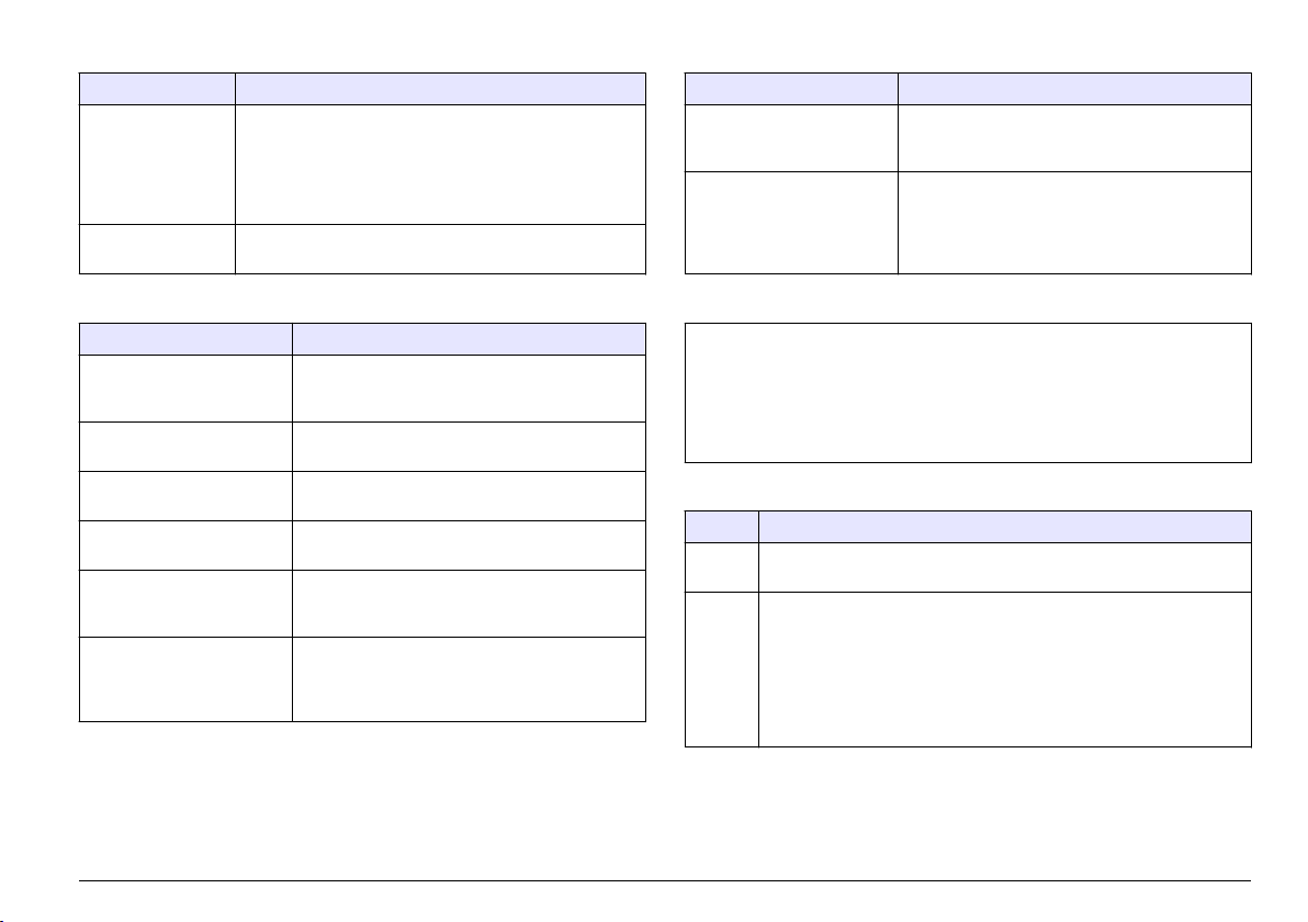
Tableau 2 Menu de configuration (suite)
Variable Description
‘PRINT’ Permet d'activer ou de désactiver l'impression
CONTRAST
(CONTRASTE)
automatique de l'imprimante en fin d'échantillonnage.
L'option SETUP (CONFIGURATION) imprime la
configuration actuelle de l'instrument (ENBL, DSBL ou
SETUP (ACTIVER, DESACTIVER ou
CONFIGURATION).
Réglez le contraste de l'écran à l'aide des touches de
navigation.
Tableau 3 Ecran : PG 2 (suite)
Variable Description
BEEP (SIGNAL SONORE) Permet de régler le signal sonore de l'avertisseur
BSAVE (ECONOMIE DE
BATTERIE)
lors de la pression d'une touche (KEY ou DSBL)
(TOUCHE ou DESACTIVE).
Fonctionnalité d'économie de batterie. Si cette
fonctionnalité est activée, l'instrument s'éteint
automatiquement après 15 minutes d'inactivité
(état de veille) ((ENBL (ACTIVE) ou DSBL
(DESACTIVE)).
Tableau 3 Ecran : PG 2
Variable Description
LANG (LANGUE) Affiche la langue utilisée pour le fonctionnement
VISC (VISCOSITE) Permet de régler les unités de mesure de la
TEMP (TEMPERATURE) Permet d'afficher les unités de température (°C
PRESS (PRESSION) Permet d'afficher les unités de pression (BAR ou
DISPL (ECRAN) Permet de régler la luminosité de l'arrière plan :
BKLT (RETROECLAIRAGE) Permet de régler le rétroéclairage de l'écran LCD.
et la commande de l'instrument (anglais, français,
allemand, espagnol et italien).
viscosité (cSt, mm2/s ou SUS).
ou °F).
PSI).
arrière-plan lumineux (NORM) (NORMAL) ou
sombre (REV) (INVERSE).
Si AUTO est sélectionné, le rétroéclairage se
désactive après 5 minutes d'inactivité (ON, OFF
ou AUTO) (ACTIVE, DESACTIVE ou AUTO).
Tableau 4 Ecran : SIZ (TAILLE)
Menu de tailles programmables. Lorsque le MODE est défini sur P/1 ml ou
P/10 ml, le menu PG2 est disponible pour n'importe lequel des huit canaux de
taille à programmer. La programmation de taille doit aller de 4,0 μm minimum à
68,0 μm maximum. La taille doit être programmée par ordre croissant, de la plus
petite taille sur le canal 1 à la plus grande sur le canal 8.
Remarque : Au besoin, utilisez F2 (DEFAULT (DEFAUT)) pour rétablir tous les paramètres de
taille par défaut.
Tableau 5 Ecran : E/S
Variable Description
UNIT_ID Définit une adresse de dispositif unique, utilisée dans la
CNTRL Réglé sur LOCAL (LOCAL) lorsque l'instrument est utilisé en mode
communication série du protocole MODBUS de l'instrument (01–99).
manuel. Réglé sur REMOTE (A DISTANCE) lorsqu'un programme
informatique pilote et commande l'échantillonnage de l'instrument.
Réglé sur DOWNLOAD (TELECHARGEMENT) lorsqu'un programme
informatique récupère les enregistrements du tampon
d'échantillonnage uniquement. Le réglage de cette variable peut
également être modifié automatiquement via le protocole série
MODBUS (LOCAL, A DISTANCE ou TELECHARGEMENT).
Français 31
Page 32

Tableau 6 Ecran : CLK
Variable Description
HEURE Heure actuelle au format 24 heures (Heures/Minutes/Secondes)
DATE Date actuelle (Mois/Jour/Année)
Fonctionnement
A V E R T I S S E M E N T
Risque d'exposition chimique. Respectez les procédures de sécurité
du laboratoire et portez tous les équipements de protection
personnelle adaptés aux produits chimiques que vous manipulez.
Consultez les fiches de données de sécurité (MSDS/SDS) à jour pour
connaître les protocoles de sécurité applicables.
Risque d'exposition chimique. Mettez au rebut les substances
chimiques et les déchets conformément aux réglementations locales,
régionales et nationales.
Procédure de prélèvement d'échantillon
Le prélèvement d'échantillon doit être effectué selon des techniques
appropriées. Il est important d'obtenir un échantillon représentatif du
niveau de contamination du système testé. Prélevez l'échantillon à partir
d'une source de liquide en mouvement.
Remarque : Tout prélèvement effectué à partir d'un flux lent risque de donner lieu
à un échantillon non représentatif. Faites fonctionner le système pendant au moins
30 minutes avant de prélever un échantillon.
Remarque : Le mode Filtre n'est plus actif. Utilisez l'un des autres modes pour
prélever un échantillon.
Lorsqu'une série de tests est terminée, il reste des échantillons dans
l'instrument. Cet instrument doit être rincé à l'aide d'un liquide qui ne
risque pas de contaminer l'échantillon suivant. Pour rincer l'instrument :
1. Utilisez le même type de liquide que le liquide prévu pour
l'échantillon suivant. Ne mélangez pas des liquides de type différent.
A T T E N T I O N
L'utilisation d'autres types de liquides entraîne des erreurs
d'échantillonnage en raison d'une incompatibilité des liquides.
2. En cas de fonctionnement en ligne, l'instrument est rincé avec le
liquide à tester. Pour un rinçage correct de l'instrument, le volume de
rinçage doit correspondre à peu près au double du volume interne du
tuyau hydraulique qui relie l'instrument et le système à tester.
3. Procédez à un rinçage optimal avant tout prélèvement d'échantillon
pour assurer une mesure d'échantillon correcte. Pour rincer
l'instrument, reportez-vous à la section Rinçage de l'instrument en
mode Flacon à la page 33 ou Rinçage de l'instrument en mode En
ligne à la page 33.
Remarque : Un nombre de rinçages excessif entraîne un engorgement
prématuré des filtres.
Avant de prélever un échantillon avec un flacon
Les sources de contamination involontairement introduites dans les
échantillons de liquide proviennent le plus souvent des flacons, tubes
plongeurs et particules en suspension dans l'air. Utilisez uniquement des
flacons d'échantillon propres et maintenez-les bouchés en permanence.
Les inexactitudes d'échantillonnage sont dues à un excès de bulles d'air
et à une contamination de l'eau. Ces deux phénomènes sont comptés
comme des particules. Pour supprimer les bulles d'air, appliquez du vide
à l'échantillon dans une chambre à vide ou placez celui-ci dans un bain
d'ultrasons pendant quelques secondes.
Les particules se déposent au fond d'un flacon d'échantillon en quelques
minutes. C'est pourquoi, il convient de secouer l'échantillon pour
remettre les particules en suspension et de le dégazer pour en retirer les
bulles.
Des échantillons fortement contaminés imprègnent le capteur et rendent
les données de comptage de particules invalides. La limite de
l'instrument est de 20 000 particules par ml avec une perte de
coïncidence de 5 % (conformément à la norme ISO 11171) et
30 000 particules par ml avec une perte de coïncidence de 10 % de
liquide pour une taille spécifique. Si la contamination est visible en
suspension dans un échantillon de liquide, les concentrations contenues
dans l'échantillon dépassent la limite de saturation de l'instrument.
Seules les particules dont la taille est supérieure à 40 μm in sont visibles
à l'œil nu.
32
Français
Page 33

Utilisez la pompe à vide d'échantillonnage de liquide pour prélever un
échantillon de liquide des réservoirs.
1. Coupez une section de tuyau propre d'une longueur suffisante pour
relier le liquide du réservoir à un point accessible à l'extérieur du
réservoir.
2. Raccordez un flacon d'échantillon à la pompe à vide
d'échantillonnage de liquide (VP633001). Installez une extrémité du
tuyau sur la pompe de manière qu'il parvienne jusqu'à l'intérieur du
flacon d'échantillon et serrez la molette.
3. Installez l'autre extrémité du tuyau dans le réservoir. Assurez-vous
de ne pas contaminer l'extrémité du tuyau.
4. A l'aide de la pompe, remplissez le flacon d'échantillon jusqu'au
niveau voulu.
5. Détachez le flacon d'échantillon de la pompe.
6. Installez le bouchon jusqu'à ce que le flacon soit prêt pour le test.
Avant de prélever une mesure en ligne
Une mesure en ligne doit être effectuée au niveau de l'un des points
suivants :
• En amont du filtre haute pression (condition après la pompe)
• En amont du filtre de retour (condition après le système)
• En amont du filtre à dérivation (condition du réservoir)
1. Détachez le tuyau hydraulique qui relie l'instrument au système à
tester.
2. Retirez le liquide préalablement testé.
3. Réglez le volume de purge sur le double du volume interne du tuyau
hydraulique.
4. Demandez conseil à un spécialiste de l'application avant toute
installation du port.
Remarque : N'installez pas d'appareil de contrôle de liquide supplémentaire
sur le tuyau d'échantillonnage hydraulique ou le port de test du système. Ces
appareils créent des bulles et pièges à particules qui entraînent des
échantillonnages inexacts.
Rinçage de l'instrument en mode Flacon
Remarque : Si le volume de rinçage dépasse la quantité de liquide présente dans
l'adaptateur de flacon, la pression pneumatique est appliquée à travers l'instrument
et évacuée via l'orifice d'écoulement. Des poches d'air se forment alors dans le
système hydraulique et entraînent des erreurs d'échantillonnage.
1. Veillez à ce qu'une bouteille de CO2 ou l'air d'atelier soit raccordé(e)
à l'instrument et que le manomètre indique une pression de 90 à
110 psi (6,2 à 7,6 bar).
2. Tournez l'adaptateur de flacon dans le sens anti-horaire pour
détacher l'adaptateur de l'instrument.
3. Remplissez le flacon d'échantillon avec le liquide de rinçage.
4. Insérez le flacon d'échantillon dans l'adaptateur de flacon et
raccordez-le à l'instrument.
5. A partir du menu principal, appuyez sur F4 pour accéder au menu de
rinçage.
6. Appuyez sur DÉBUTER.
7. Appuyez sur F1 (SOL ON) (SOL. ACTIVE). L'adaptateur de flacon se
met sous pression et le liquide commence à sortir par l'orifice
d'écoulement. La quantité de liquide de rinçage s'affiche à l'écran.
8. Lorsque l'instrument est rincé, appuyez sur CANCEL (ANNULER)
pour arrêter le liquide et revenir au menu principal.
Rinçage de l'instrument en mode En ligne
1. Raccordez l'adaptateur en ligne à l'instrument. Insérez le tube
plongeur dans l'orifice au centre de l'adaptateur et tournez
l'adaptateur dans le sens horaire jusqu'à verrouiller le tube plongeur.
2. Raccordez le tuyau hydraulique à l'adaptateur en ligne à l'aide d'un
filetage de raccord de tuyau de test Minimess®.
3. Reliez l'autre extrémité du tuyau hydraulique au système à tester.
4. A partir du menu principal, appuyez sur F4 pour accéder au menu de
rinçage.
5. Appuyez sur DÉPART. Le liquide s'échappe par l'orifice
d'écoulement et la quantité de liquide s'affiche à l'écran.
Français
33
Page 34

6. Lorsque l'instrument est rincé, appuyez sur CANCEL (ANNULER)
pour arrêter le processus de rinçage, puis revenez au menu
principal.
Remarque : Si l'instrument est hors tension pendant le rinçage du système, le
contrôleur de flux interne reste ouvert et le liquide continue à s'écouler. Il
convient de toujours arrêter le processus de rinçage et d'attendre cinq
secondes avant de mettre l'instrument hors tension.
Remarque : Le système reste pressurisé après le retrait de la source de
pression. Pour supprimer la pression du système, retirez la source de pression
et appuyez sur START (DEMARRER), ou sélectionnez « SOL ON » (SOL.
ACTIVE), puis « SOL OFF » (SOL. DESACTIVE) jusqu'à ce que le manomètre
indique 0 psi.
Compatibilité avec les liquides
L'instrument est compatible avec la plupart des liquides à base de
pétrole et ester phosphoriques compris dans les plages de viscosité et
de température spécifiées. En cas de doute sur la compatibilité d'un
liquide, vérifiez sa compatibilité en consultant la liste des matériaux
mouillés figurant dans les Caractéristiques à la page 21. Si la
compatibilité de ce liquide n'est pas précisée, adressez-vous à un
représentant du fabricant local pour obtenir des recommandations sur
l'utilisation de ce liquide dans l'instrument.
A V I S
Les composants internes de cet instrument ne sont pas compatibles avec l'eau.
L'eau entraîne des dysfonctionnements et un endommagement de l'instrument.
L'instrument n'est compatible qu'avec des liquides qui présentent des propriétés
lubrifiantes.
Prélèvement d'échantillon en mode Flacon
1. Introduisez un échantillon de liquide dans l'adaptateur de flacon.
2. Raccordez l'adaptateur à l'instrument.
3. A partir du menu principal, appuyez sur F1 (SETUP)
(CONFIGURATION) pour accéder au menu de configuration.
4. Réglez le mode d'échantillonnage sur BOTTLE (FLACON) et
assurez-vous que les autres variables de fonctionnement soient
correctement programmées. Pour plus de renseignements, référezvous à la section Caractéristiques à la page 21.
5. Vérifiez qu'une bouteille de CO2 ou que l'air d'atelier est bien relié(e)
à l'instrument.
6. Veillez à ce que le manomètre indique une pression de 90 à 110 psi
(6,2 à 7,6 bar). En raison des divergences de régulation, la pression
indiquée sur le manomètre monte à 120 psi (8,3 bar) en l'absence de
flux. La pression redescend lorsque l'échantillonnage démarre.
7. Tournez l'adaptateur de flacon dans le sens anti-horaire pour le
détacher de l'instrument.
8. Remplissez le flacon d'échantillon du liquide à tester.
9. Placez le flacon d'échantillon dans l'adaptateur de flacon.
10. Raccordez l'adaptateur d'échantillon à l'instrument.
11. Assurez-vous que le flacon à déchets conserve le liquide.
12. Appuyez sur DÉPART. Le processus d'échantillonnage démarre.
Lorsque le processus est terminé, les résultats du test sont transmis
au tampon, affichés à l'écran et/ou imprimés.
Prélèvement d'échantillon en mode En ligne
En mode En ligne, les échantillons proviennent directement d'un
système hydraulique. Les sources de pression externe de CO2 ou d'air
d'atelier ne sont pas utilisées, mais elles restent raccordées pendant ce
processus d'échantillonnage.
1. A partir du menu principal, appuyez sur F1 (SETUP)
(CONFIGURATION) pour accéder au menu de configuration.
2. Réglez le mode d'échantillonnage sur ONLINE (EN LIGNE) et réglez
le nombre de cycles, le temps de maintien et le volume de purge du
programme. Le volume de purge doit correspondre
approximativement au double du volume interne du tuyau
hydraulique qui relie l'instrument au système.
3. Veillez à ce que les autres variables de fonctionnement soient
correctement programmées. Pour plus de renseignements, référezvous à la section Configuration des variables de fonctionnement
à la page 29.
4. Pour relier l'adaptateur en ligne à l'instrument, introduisez le tube
plongeur dans l'orifice au centre de l'adaptateur, puis tournez le
tuyau dans le sens horaire jusqu'à ce que l'adaptateur soit bloqué.
34
Français
Page 35

5. Raccordez un tuyau hydraulique avec un filetage de tuyau
Minimess®1 à l'adaptateur en ligne.
6. Reliez l'autre extrémité du tuyau hydraulique au système à tester.
7. Appuyez sur DÉPART. Le processus d'échantillonnage démarre.
Lorsque le processus est terminé, les résultats du test sont transmis
au tampon, affichés à l'écran et/ou imprimés.
Remarque : Si l'instrument est hors tension pendant le rinçage de l'instrument,
le contrôleur de flux interne reste ouvert et permet au liquide de circuler. Il
convient de toujours arrêter le processus de rinçage et d'attendre cinq
secondes avant de mettre l'instrument hors tension.
Résultats des tests
Les données de comptage indiquent le nombre de comptages par cycle
et la moyenne des trois cycles. Un rapport de test indique :
• Type d'échantillon
• Numéro de série de l'unité de prélèvement de l'échantillon
• Date et heure du prélèvement d'échantillon
• Volume par cycle d'échantillonnage
• Débit
• Viscosité mesurée
• Température de liquide mesurée
• Unités de concentration
• Format de nettoyage mesuré
• Données de comptage par taille en microns
Pour le rapport de norme ISO, le volume de cycle indique le niveau le
plus bas du code de contamination.
• Pour un volume de cycle de 5 ml, le niveau de code ISO le plus bas
signalé est 03/03/03.
• Pour un volume de cycle de 10 ml, le niveau de code ISO le plus bas
signalé est 02/02/02.
• Pour un volume de cycle de 20 ml, le niveau de code ISO le plus bas
signalé est 01/01/01.
Pour plus d'informations à ce sujet, reportez-vous à la section
« Contamination des fluides hydrauliques – Code » de la norme
ISO 4406 pour calculer le niveau de contamination par particules
solides.
La température affichée correspond à la température en bout de circuit
hydraulique (à l'intérieur du contrôleur de flux). Il ne s'agit pas d'une
mesure de la température du liquide en entrée. Le circuit hydraulique a
des masses thermiques qui influencent la température du liquide.
• Si l'instrument est plus froid que le liquide, la température du liquide
chute pendant l'échantillonnage du liquide.
• Si l'instrument est plus chaud, la température augmente pendant
l'échantillonnage du liquide.
Interprétation des résultats : comparez les résultats relevés aux plages
correspondantes ciblées pour le système testé. Le traitement ou le
remplacement du liquide peut alors avoir lieu.
Fonctionnement du tampon
Affichage du contenu
1. Affichez le contenu du tampon à partir du menu du tampon :
• LAST SAMPLE (DERNIER ECHANTILLON) : affiche les résultats
du dernier échantillon.
• LIST BUFFER (LISTE TAMPON) : affiche les huit derniers noms
d'échantillon pour un examen plus approfondi.
• SEARCH BUFFER (RECHERCHE D'ECHANTILLON) : recherche
le nom d'un échantillon particulier. Saisissez le nom complet ou
une partie du nom de l'échantillon.
2. Une fois l'échantillon sélectionné, appuyez sur les touches de
fonction correspondantes pour afficher l'échantillon suivant ou
précédent. Le contenu du tampon s'affiche dans la configuration
actuellement programmée.
3. Pour afficher les résultats dans une configuration différente, modifiez
les variables de fonctionnement selon une autre configuration, puis
consultez à nouveau le contenu du tampon.
Français
35
Page 36

Suppression ou impression de données
Utilisez le menu du tampon pour supprimer ou imprimer le contenu du
tampon.
1. Appuyez sur F2 (DEL BUF) (SUPPRESSION TAMPON) pour
supprimer l'intégralité du contenu du tampon. L'instrument affiche un
message de confirmation vous demandant d'accepter ou d'annuler
l'opération.
2. Appuyez sur F3 (PRT BUF) (IMPRESSION TAMPON) pour imprimer
l'intégralité du contenu du tampon. L'instrument affiche un message
de confirmation vous demandant d'accepter ou d'annuler l'opération.
3. Appuyez sur F1 (DEL SMP) (SUPPRESSION ECHANTILLON) ou F2
(PRT SMP) (IMPRESSION ECHANTILLON) dans le menu de
comptage moyen (AVG CNT) (COMPTAGE MOYEN) pour supprimer
ou imprimer le résultat d'un test d'échantillon en particulier.
Lorsqu'une sélection d'échantillon est affichée, le menu de comptage
moyen est disponible.
Affichage des données d'échantillon
Lorsqu'un échantillon est sélectionné, l'instrument affiche les statistiques
relatives à cet échantillon. Appuyez sur la touche de fonction de
comptage moyen (AVG CNT) pour afficher le reste des données
d'échantillon
Maintenance
D A N G E R
Dangers multiples. Seul le personnel qualifié doit effectuer les tâches
détaillées dans cette section du document.
Nettoyage de l'instrument
A T T E N T I O N
Risque d’incendie. Ne pas utiliser d'agents inflammables pour nettoyer
l'appareil.
A V I S
Assurez-vous de ne pas courber le tube plongeur ni rayer l'extrémité inférieure
au niveau du raccord étanche. Tout endommagement risque d'entraîner une fuite
ou un désalignement de l'adaptateur en ligne.
1. Nettoyez l'instrument à l'aide d'une brosse de nettoyage et d'une
solution glycolée.
2. Rincez l'instrument.
Remplacement du filtre
Pour retirer le filtre, reportez-vous à la Figure 5.
Risque de blessures corporelles. Ne retirez jamais les caches de
l'appareil. L'appareil contient un laser susceptible de provoquer des
blessures en cas d'exposition.
36 Français
A V E R T I S S E M E N T
Page 37

Figure 5 Retrait du filtre
Mise en charge de la batterie
Alimentez l'instrument par :
• une batterie rechargeable interne
• une alimentation électrique externe
Avec une batterie interne entièrement chargée, l'instrument peut traiter
au minimum 100 échantillons avant qu'il soit nécessaire de charger la
batterie. L'alimentation électrique externe permet également de charger
la batterie interne. L'instrument peut être utilisé pendant le chargement
de la batterie interne.
Eléments à préparer :
• Alimentation externe
• Cordon d'alimentation
1. Branchez le cordon d'alimentation sur l'alimentation externe.
2. Branchez l'autre extrémité du cordon d'alimentation sur une prise de
courant.
3. Branchez la fiche d'alimentation externe à l'instrument au niveau du
port d'alimentation (situé sous le manomètre).
4. Vous devez entendre un déclic. Veillez à ce que le voyant d'état de
chargement (situé sur le clavier) soit allumé. Ce voyant indique l'un
des trois modes d'état de chargement :
Indicateur Statut
Vert fixe Chargement
Vert clignotant Mode de maintenance
Rouge fixe Défaut de chargement de la batterie
Chargement de papier dans l'imprimante
1. Ouvrez le capot de l'imprimante.
2. Placez le papier d'impression dans l'instrument, de manière que le
papier se présente par le bas du rouleau.
Français
37
Page 38

3. Pendant que l'instrument est sous tension, insérez le papier dans
l'imprimante et appuyez sur LINE FEED (ALIMENTATION LIGNE).
Le papier passe à travers l'imprimante.
4. Pliez le jeu du rouleau de papier et poussez-le dans le support de
papier.
5. Soulevez l'extrémité libre du papier et fermez le capot de
l'imprimante.
6. Retirez l'excès de papier.
Remarque : Si le papier n'est pas correctement aligné, soulevez le levier du
côté gauche de l'imprimante pour rehausser le chariot d'impression. Tirez sur
le papier en le redressant et alignez-le. Rabaissez le chariot avant d'utiliser
l'imprimante.
Désencrassement du capteur d'écoulement
A T T E N T I O N
Risque d'exposition chimique. Respectez les procédures de sécurité
du laboratoire et portez tous les équipements de protection
personnelle adaptés aux produits chimiques que vous manipulez.
Consultez les fiches de données de sécurité (MSDS/SDS) à jour pour
connaître les protocoles de sécurité applicables.
A V I S
L'application d'une force excessive peut entraîner l'endommagement de la
brosse, voire de la cellule. Si la brosse ne peut pas être introduite dans la cellule,
tirez sur la brosse pour l'extraire et vérifiez l'absence de dommages au niveau de
l'extrémité nettoyante.
Prenez toutes les mesures de précaution pour éviter l'endommagement
de l'instrument et les blessures.
Eléments à préparer :
• Tissu absorbant
• Clé Allen
• Brosse de nettoyage
2. Insérez la brosse dans l'orifice de nettoyage jusqu'à ce qu'une
résistance se fasse sentir.
3. Poussez délicatement la brosse dans la cellule d'écoulement du
capteur en effectuant un mouvement circulaire.
4. Faites fonctionner l'instrument avec un liquide d'échantillon propre.
Pour purger l'air emprisonné dans la conduite d'écoulement :
a. Posez un tissu absorbant sur la clé et desserrez légèrement le
bouchon d'écoulement pendant le cycle d'échantillonnage. Le
liquide et l'air s'échappent rapidement dès que le bouchon est
desserré.
b. Poursuivez le processus jusqu'à ce qu'il n'y ait plus d'air qui
s'échappe de l'orifice.
5. Serrez bien le bouchon de l'orifice d'écoulement. Pour éviter
d'endommager le filetage, veillez à ne pas serrer excessivement le
bouchon.
Figure 6 Désencrassement du capteur
1. Posez un tissu absorbant sous l'instrument, de manière à récupérer
le liquide qui s'échapperait de l'orifice d'écoulement. Voir Figure 6.
38 Français
Page 39

Etalonnage
Retournez l'instrument une fois par an pour procéder à son étalonnage.
La date d'étalonnage est indiquée sur l'étiquette d'étalonnage située sur
la plaque signalétique à l'intérieur de la porte gauche (derrière le
conteneur à déchets). Chaque instrument est étalonné en usine.
Dépannage
Pour obtenir de l'aide sur les problèmes potentiels, reportez-vous aux
Tableau 7 et Tableau 8.
En cas de dysfonctionnement du programme et si les paramètres par
défaut de l'instrument doivent être rétablis, appuyez sur la touche F4 et
maintenez-la enfoncée pendant la remise sous tension de l'instrument.
Remarque : Cette opération efface l'intégralité du contenu du tampon et rétablit les
paramètres par défaut de toutes les variables de fonctionnement. Un message par
défaut et le numéro du micrologiciel s'affichent lorsque l'instrument réinitialise son
système.
Tableau 7 Erreurs critiques
Erreur Cause possible Solution
Défaillance du
contrôleur de flux
L'unité ne parvient pas à
trouver l'interrupteur
HOME (ORIGINE) sur le
contrôleur de flux lors de
l'initialisation du système
ou à la fin d'un test
d'échantillonnage.
Il y a un
dysfonctionnement du
contrôleur de flux
De l'air est emprisonné
dans la tuyauterie
hydraulique interne.
(PODS uniquement)
L'instrument n'a pas été
purgé avant une
modification de la viscosité
du liquide d'échantillon.
(PODS uniquement)
Démarrez à nouveau
l'instrument.
Contactez l’assistance
technique.
Retirez l'air de la tuyauterie
hydraulique interne, y
compris de l'orifice
d'écoulement, à l'aide d'un
liquide propre.
Nettoyez le système à l'aide
d'un nouveau liquide.
Français 39
Page 40

Tableau 7 Erreurs critiques (suite)
Erreur Cause possible Solution
Défaillance de la
régulation du débit
La pression externe a
diminué lors du test
d'échantillonnage.
L'instrument n'a pas été
purgé avant une
modification de la viscosité
du liquide d'échantillon.
Le volume de liquide
d'échantillon est
insuffisant.
Une tentative de rinçage
du système a été
effectuée. (GlyCount
uniquement)
Veillez à ce que la source
d'air externe soit stable et
réglée sur une valeur proche
de 100 psi. Vérifiez
l'absence de fuites au
niveau du joint torique du
gobelet d'échantillon.
Purge de l'instrument.
Augmentez le volume de
liquide de l'échantillon.
Rincez l'instrument. Veillez à
ce que le liquide
d'échantillon reste dans le
circuit d'écoulement.
Tableau 7 Erreurs critiques (suite)
Erreur Cause possible Solution
Débit bas, viscosité
élevée possible
La pression
hydraulique de
l'échantillonnage en
ligne est
insuffisante.
Haute pression
détectée
La pression externe a
diminué pendant le test
d'échantillonnage.
L'instrument n'a pas été
purgé avant une
modification de la viscosité
du liquide d'échantillon.
La viscosité du liquide
d'échantillon est trop
élevée. (PODS
uniquement)
Le bouchon du tube
plongeur n'a pas été retiré.
La source de pression
hydraulique est
insuffisante.
Une défaillance du
régulateur hydraulique
interne s'est produite ou le
paramètre de réglage est
en dehors des tolérances.
Veillez à ce que la source
d'air externe soit stable et
réglée sur une valeur proche
de 100 psi. Vérifiez
l'absence de fuites au
niveau du joint torique du
gobelet d'échantillon.
Purge de l'instrument.
Diminuez le débit ou diluez
l'échantillon à l'aide d'un
liquide propre, filtré et
miscible adapté, qui réduira
la viscosité de l'échantillon
de manière qu'elle soit
comprise dans la plage du
compteur (10–424 cSt).
Retirez le bouchon.
Vérifiez que la pression du
liquide est supérieure à
40 psi pendant toute la
durée d'échantillonnage.
Vérifiez l'absence de fuites
au niveau du joint torique de
l'adaptateur en ligne.
Contactez l’assistance
technique.
40 Français
Page 41

Tableau 7 Erreurs critiques (suite)
Erreur Cause possible Solution
Pression faible La source de pression
La pression a chuté
jusqu'à un niveau
insuffisant
externe est insuffisante.
Le bouchon du tube
plongeur est installé.
La pression externe a
diminué lors du test
d'échantillonnage.
La viscosité du liquide
d'échantillon est trop
élevée. (PODS
uniquement)
Il y a une défaillance du
régulateur hydraulique
interne ou un paramètre
de réglage en dehors des
tolérances.
Veillez à ce que la source
d'air externe soit stable et
réglée sur une valeur proche
de 100 psi. Diminuez le
débit, surtout pour les
liquides à haute viscosité.
Vérifiez l'absence de fuites
au niveau du joint torique du
gobelet d'échantillon.
Retirez le bouchon du tube
plongeur.
Veillez à ce que la source
d'air externe soit stable et
réglée sur une valeur proche
de 100 psi. Diminuez le
débit, surtout pour les
liquides à haute viscosité.
Vérifiez l'absence de fuites
au niveau du joint torique du
gobelet d'échantillon.
Diminuez le débit ou diluez
l'échantillon à l'aide d'un
liquide propre, filtré et
miscible adapté, qui réduira
la viscosité de l'échantillon
de manière qu'elle soit
comprise dans la plage du
compteur (10–424 cSt).
Contactez l’assistance
technique.
Tableau 8 Erreurs non critiques
Erreur Cause possible Solution
ERREUR DE LA
CELLULE DU
CAPTEUR
D'ECOULEMENT
La zone de
visualisation de la
cellule du capteur est
obstruée, ce qui
empêche le détecteur
de voir la lumière du
laser.
Le volume de liquide
d'échantillon est
insuffisant.
Le capteur n'est pas
correctement étalonné.
Cela entraîne un signal
faible.
L'échantillon est
contaminé par de l'eau
ou par un niveau de
particules élevé.
Défaillance
électronique du
capteur ou du laser.
(GlyCount uniquement)
Suivez la procédure de
nettoyage de la cellule,
décrite à la section
Désencrassement du
capteur d'écoulement
à la page 38.
Augmentez le volume de
liquide de l'échantillon.
Retournez l'unité chez le
fabricant pour qu'il procède à
un étalonnage ou à une
réparation
Eliminez l'eau ou essayez un
autre échantillon. Si
l'échantillon est fortement
contaminé, diluez-le.
Retournez l'unité chez le
fabricant pour qu'il procède à
un étalonnage ou à une
réparation
Français 41
Page 42
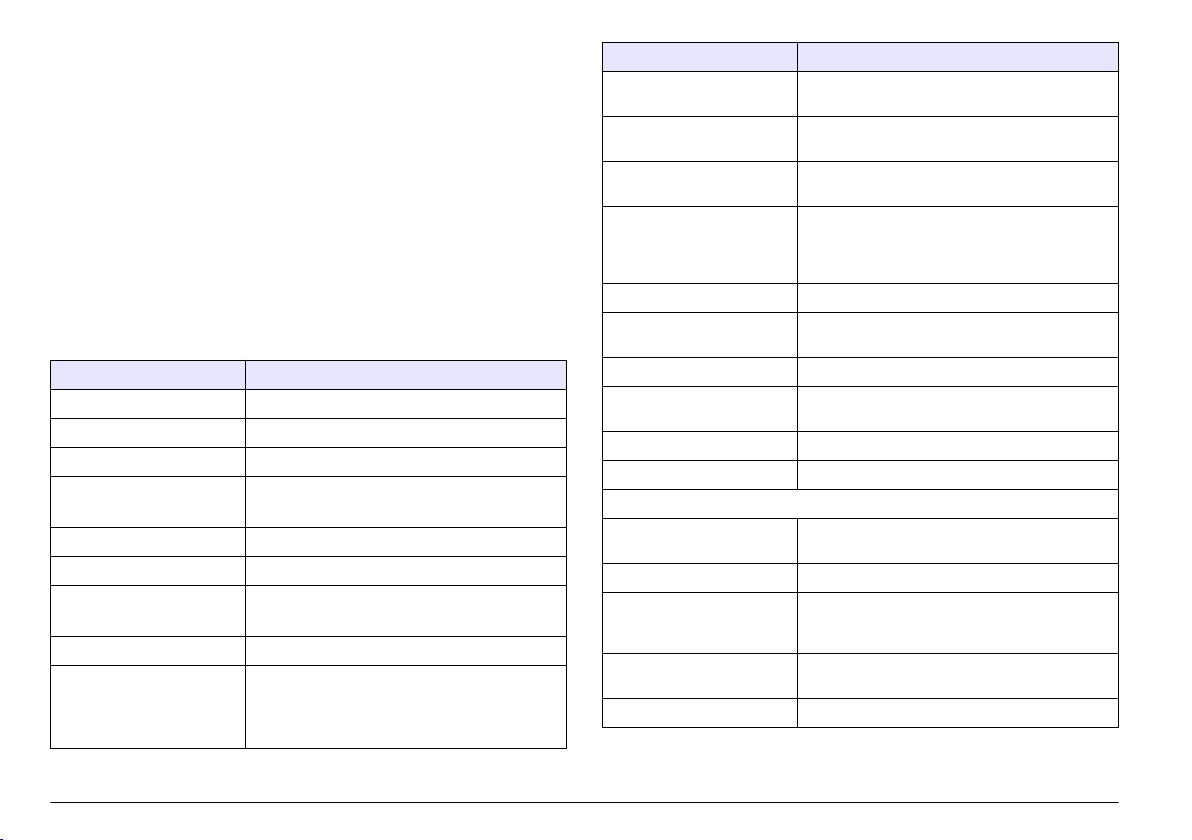
Índice de contenidos
Información adicional en la página 42
Especificaciones en la página 42
Información general en la página 43
Instalación en la página 46
Puesta en marcha en la página 48
Interfaz del usuario y navegación
en la página 48
Funcionamiento en la página 53
Mantenimiento en la página 57
Solución de problemas
en la página 60
Información adicional
En el sitio web del fabricante encontrará información adicional.
Especificaciones
Las especificaciones están sujetas a cambios sin previo aviso.
Especificación Detalles
Dimensiones (P. x An. x Al.) 18,5 x 33,0 x 40,0 cm (7,3 x 12,5 x 15,7 pulg.)
Peso 9,3 kg (20,5 libras)
Número de canales 8
Tamaño de canales ISO-MTD 4, 4,6, 6, 9,8, 14, 21,2, 38, 68 μm
ACFTD ~1, 2, 5, 10, 25, 50, 100 μm
Caudal De 15 a 50 ml/min (automático/manual)
Fuente de luz Láser de clase 3B, 810-852 nm, 50 mW máximo
Calibración ISO MTD (basada en la normativa ISO 11171)
ISO 11171 completa, opcional
Eficiencia del recuento JIS B9925:1997
Límite de concentración 20.000 partículas por ml con un 5% de pérdida
de coincidencia (de conformidad con la
normativa ISO 11171)
30.000 partículas/ml con un 10% de coincidencia
Especificación Detalles
Volumen de muestra 3 ejecuciones (promedio) de 5, 10 o
Rango de temperatura del
líquido
Temperatura del líquido
medido
Rango de viscosidad De 10 a 424 cSt (de 59 a 2000 SUS)
Materiales impregnados Aluminio, acero inoxidable, zafiro, PTFE y Aflas
Clasificación de limpieza ISO 4406-1991, ISO 4406-1999, NAS 1638, MIL-
Almacenamiento de datos 500 registros de muestras
Comunicación en serie de
entrada/salida
Altitud 2000 m (6561,7 pies)
Certificaciones CE
Funcionamiento de la botella
Volumen de purga De 15 a 30 ml (automático/manual)
Cartucho CO2, reemplazable, recargable
Tiempo de funcionamiento 60 muestras (botella de muestreo de 120 ml)
Aire comprimido De 620 a 758 kPa (de 90 a 100 psi; de 6,2 a
Presión del líquido De 40 a 5000 psi (de 2,75 a 345 bares)
20 ml/ejecución (programable)
De 0 a 90 °C a 25 °C de temperatura ambiente
(de 32 a 194 °F a 77 °F)
De 0 a 100 °C, ±0,5 °C (de 32 a 212 °F, ±0,9 °F)
Para la medición de la viscosidad, el rango de
viscosidad oscila entre 10 y 424 cSt ±20% al
valor.
STD-1246C, SAE AS 4059, NAVAIR 01-1A-1
RS232
Programable
Programable, tiempo de espera y número de
muestra
7,6 bares) limpio, seco
®
42 Español
Page 43

Especificación Detalles
Alimentación eléctrica
Entrada de CD 24 V CD, 2 A máximo
Adaptador de CA Universal 100–240 V CA, 50–60 Hz, 60 W
Batería recargable Níquel-hidruro metálico
Tiempo de funcionamiento 100 muestras o 4 horas de funcionamiento
Tiempo de recarga 2,5 horas
Entorno
Entorno de funcionamiento De 0 a 55 °C (de 32 a 131 °F), del 5 al 95% de
Almacenamiento De -40 a 70 °C (de -40 a 158 °F), hasta el 98%
ininterrumpido
humedad relativa, sin condensación
de humedad relativa, sin condensación
Información general
En ningún caso el fabricante será responsable de ningún daño directo,
indirecto, especial, accidental o resultante de un defecto u omisión en
este manual. El fabricante se reserva el derecho a modificar este
manual y los productos que describen en cualquier momento, sin aviso
ni obligación. Las ediciones revisadas se encuentran en la página web
del fabricante.
Información de seguridad
A V I S O
El fabricante no es responsable de ningún daño debo a un mal uso de este
producto incluyendo, sin limitación, daños directos, fortuitos o circunstanciales y
reclamos sobre los daños que no estén recogidos en la legislación vigente. El
usuario es el responsable de la identificación de los riesgos críticos y de tener los
mecanismos adecuados de protección de los procesos en caso de un posible
mal funcionamiento del equipo.
Lea todo el manual antes de desembalar, instalar o trabajar con este
equipo. Ponga atención a todas las advertencias y avisos de peligro. El
no hacerlo puede provocar heridas graves al usuario o daños al equipo.
Asegúrese de que la protección proporcionada por el equipo no está
dañada. No utilice ni instale este equipo de manera distinta a lo
especificado en este manual.
Uso de la información sobre riesgos
P E L I G R O
Indica una situación potencial o de riesgo inminente que, de no evitarse,
provocará la muerte o lesiones graves.
A D V E R T E N C I A
Indica una situación potencial o inminentemente peligrosa que, de no evitarse,
podría provocar la muerte o lesiones graves.
P R E C A U C I Ó N
Indica una situación potencialmente peligrosa que podría provocar una lesión
menor o moderada.
Indica una situación que, si no se evita, puede provocar daños en el instrumento.
Información que requiere especial énfasis.
A V I S O
Etiquetas de precaución
Lea todas las etiquetas y rótulos adheridos al instrumento. En caso
contrario, podrían producirse heridas personales o daños en el
instrumento. Se incluye un símbolo, en caso de estar rotulado en el
equipo, con una indicación de peligro o de advertencia en el manual.
Español
43
Page 44

Este símbolo (en caso de estar colocado en el equipo) hace
referencia a las instrucciones de uso o a la información de seguridad
del manual.
El equipo eléctrico marcado con este símbolo no se podrá desechar
por medio de los sistemas europeos públicos de eliminación después
del 12 de agosto de 2005. De acuerdo con las regulaciones locales y
nacionales europeas (Directiva UE 2002/96/EC), ahora los usuarios
de equipos eléctricos en Europa deben devolver los equipos viejos o
que hayan alcanzado el término de su vida útil al fabricante para su
eliminación sin cargo para el usuario.
Nota: Para devolver equipos para su reciclaje, póngase en contacto con el
fabricante o distribuidor para así obtener instrucciones acerca de cómo
devolverlos y desecharlos correctamente. Esto es aplicable a equipos que hayan
alcanzado el término de su vida útil, accesorios eléctricos suministrados por el
fabricante o distribuidor y todo elemento auxiliar.
Este símbolo indica la necesidad de usar protectores para ojos.
Producto láser de clase 1
Este instrumento está clasificado como producto láser de clase 1. Este
producto cumple la normativa IEC/EN 60825-1:2007 y 21 CFR 1040.10,
excepto para las desviaciones conforme al aviso sobre láser nº 50, con
fecha del 24 de junio de 2007.
Número de acceso de la FDA estadounidense 9912262-006. Este
producto contiene un láser clase 3B de 810-852 nm y 50 mW que no
puede reparar el usuario.
Certificación
Reglamentación canadiense sobre equipos que provocan
interferencia, IECS-003, Clase A
Registros de pruebas de control del fabricante.
Este aparato digital de clase A cumple con todos los requerimientos de
las reglamentaciones canadienses para equipos que producen
interferencias.
Cet appareil numérique de classe A répond à toutes les exigences de la
réglementation canadienne sur les équipements provoquant des
interférences.
FCC Parte 15, Límites Clase "A"
Registros de pruebas de control del fabricante. Este dispositivo cumple
con la Parte 15 de las normas de la FCC estadounidense. Su operación
está sujeta a las siguientes dos condiciones:
1. El equipo no puede causar interferencias perjudiciales.
2. Este equipo debe aceptar cualquier interferencia recibida, incluyendo
las interferencias que pueden causar un funcionamiento no deseado.
Los cambios o modificaciones a este equipo que no hayan sido
aprobados por la parte responsable podrían anular el permiso del
usuario para operar el equipo. Este equipo ha sido probado y
encontrado que cumple con los límites para un dispositivo digital Clase
A, de acuerdo con la Parte 15 de las Reglas FCC. Estos límites están
diseñados para proporcionar una protección razonable contra las
interferencias perjudiciales cuando el equipo está operando en un
entorno comercial. Este equipo genera, utiliza y puede irradiar energía
de radio frecuencia, y si no es instalado y utilizado de acuerdo con el
manual de instrucciones, puede causar una interferencia dañina a las
radio comunicaciones. La operación de este equipo en un área
residencial es probable que produzca interferencia dañina, en cuyo caso
el usuario será requerido para corregir la interferencia bajo su propio
cargo. Pueden utilizarse las siguientes técnicas para reducir los
problemas de interferencia:
1. Desconecte el equipo de su fuente de alimentación para verificar si
éste es o no la fuente de la interferencia.
2. Si el equipo está conectado a la misma toma eléctrica que el
dispositivo que experimenta la interferencia, conecte el equipo a otra
toma eléctrica.
3. Aleje el equipo del dispositivo que está recibiendo la interferencia.
4. Cambie la posición de la antena del dispositivo que recibe la
interferencia.
5. Trate combinaciones de las opciones descritas.
44
Español
Page 45
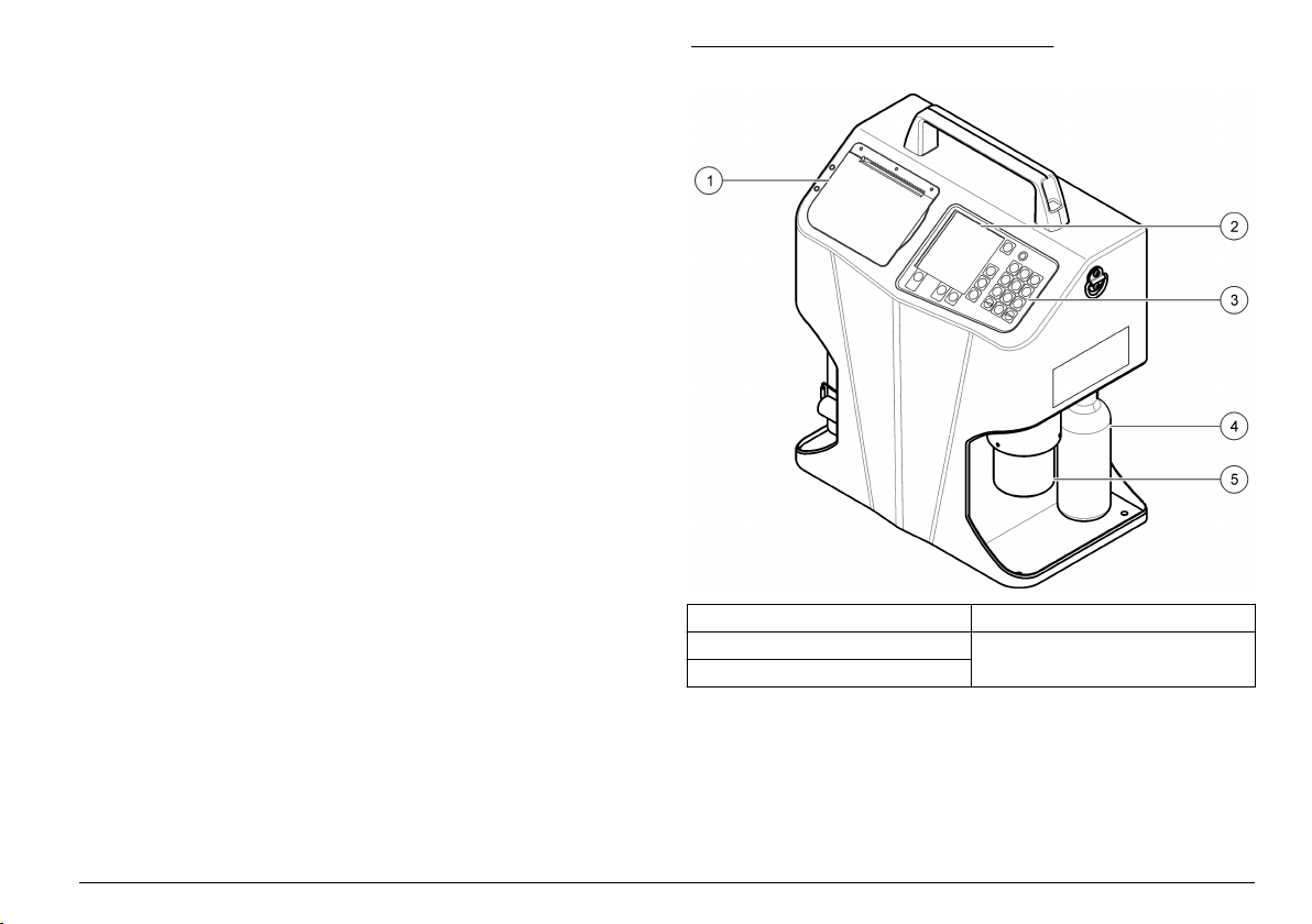
Descripción general del producto
El sistema de diagnóstico de aceites portátil(PODS) se utiliza para
medir, mantener e informar sobre la contaminación de los aceites que
son importantes para el funcionamiento fiable de los sistemas
hidráulicos. El instrumento analiza los lubricantes y líquidos
presurizados en modos de muestreo en botella o en línea sin interrumpir
el funcionamiento de la máquina.
El instrumento es compatible con líquidos hidráulicos a base de ésteres
de fosfato y petróleo (incluidos los líquidos MIL-H-5606 y Skydrol®). El
instrumento se suministra con botellas rellenables de CO2 para su uso
sobre el terreno y con una conexión para el puerto de aire comprimido
para su uso en fábrica. Para conocer las diferentes vistas del
instrumento, consulte la Figura 1 y la Figura 2.
Nota: Debido a las restricciones de envío de los Estados Unidos, el instrumento se
envía con botellas de CO2 vacías.
Figura 1 Descripción general del producto
1 Puerta de la impresora 4 Botella de CO
2 Pantalla 5 Adaptador para botella de muestreo
3 Teclado
2
Español 45
Page 46

Figura 2 Vista lateral
Figura 3 Componentes del instrumento
1 Botella para residuos 5 Indicador de presión
2 Asa 6 Puerto para entrada de
3 Argolla en D para correas de
transporte a hombros
4 Puerto de limpieza 8 Puerto para aire comprimido
alimentación eléctrica
7 Puerto RS232
Componentes del producto
Asegúrese de haber recibido todos los componentes. Consulte la
Figura 3. Si faltan artículos o están dañados, póngase en contacto con
el fabricante o el representante de ventas inmediatamente.
46
Español
1 Instrumento 4 Cable de
2 Adaptador de
alimentación de CA
3 Botella de CO2, vacía
(2x)
alimentación
5 Botella de muestreo
(x10)
6 Llave Allen 9 Disco de software
7 Papel para impresora
(x2)
8 Cepillo de limpieza
(2x)
Instalación
A D V E R T E N C I A
Peligros diversos. Sólo el personal cualificado debe realizar las tareas
descritas en esta sección del documento.
Conexión de la presión externa
Conecte la botella de CO2 suministrada o el aire comprimido al
instrumento para proporcionar presión externa.
Page 47
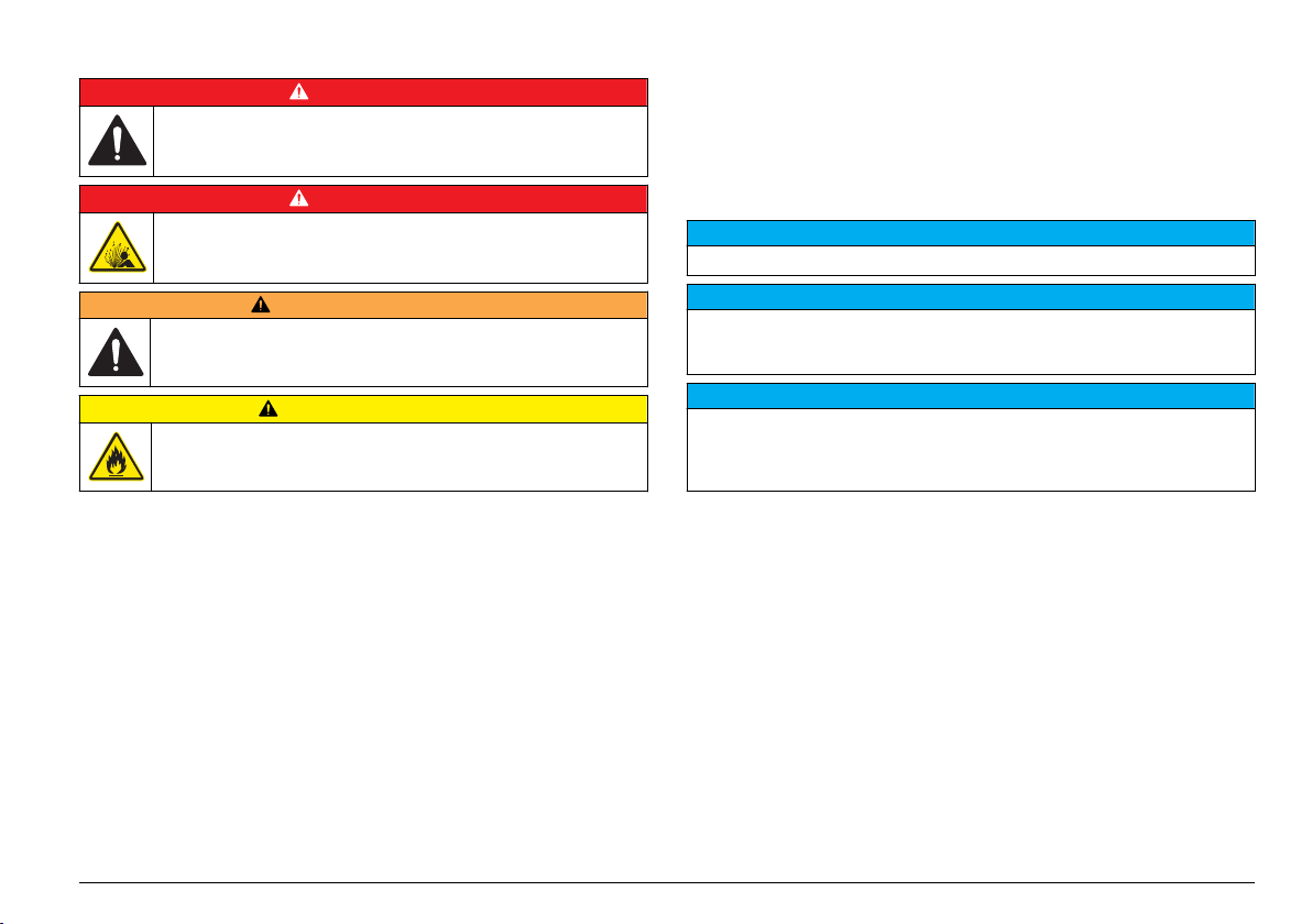
Conexión de la botella de CO
Peligros diversos. Sólo el personal cualificado debe realizar las tareas
descritas en esta sección del documento.
Peligro de explosión. Para garantizar el uso seguro del instrumento,
siga específicamente las precauciones e instrucciones.
A D V E R T E N C I A
Peligro de lesión personal. Los sistemas incluidos contienen altas
presiones. Un técnico cualificado debe eliminar la presión del sistema
antes de instalar o retirar el instrumento.
Peligro de incendio. No utilice agentes inflamables para limpiar el
instrumento.
2
P E L I G R O
P E L I G R O
P R E C A U C I Ó N
La botella de CO2 es una botella de gas comprimido con alta presión.
No altere esta botella de ningún modo. Utilice solo botellas de CO
suministradas por el fabricante. Utilice la botella únicamente del modo
2
en que se indica en este manual. Consulte el texto de la botella para
obtener información sobre cómo debe almacenarse y eliminarse.
No exponga la botella presurizada a temperaturas superiores a 177 °C
(350 °F). Las botellas expuestas al fuego o calentadas a temperaturas
superiores a 177 °C (350 °F) deben desecharse. Deje que la botella se
enfríe antes de desecharla.
Mantenga el tapón protector en las botellas de CO2 que no se estén
utilizando.
Solo el personal formado puede instalar o retirar las válvulas.
Utilice solo un detergente suave y agua para limpiar el cilindro. El
empleo de limpiadores cáusticos puede corroer las juntas de presión o
las paredes del tanque y provocar una liberación incontrolada de presión
o una rotura.
Asegúrese de que el adaptador para botellas está instalado
correctamente cuando se inicie la presurización. Si el adaptador para
botellas no está instalado correctamente, puede desprenderse del
instrumento y provocar daños materiales o lesiones personales.
Debido a la gran variedad de disposiciones legales y de normas de
envío, las botellas de CO2 suministradas en el contenedor de envío
están vacías. Asegúrese de que un proveedor de CO2 certificado rellena
las botellas.
A V I S O
No retire ni cubra la etiqueta de la botella.
Únicamente el personal con la formación adecuada debe rellenar y transportar
esta botella de conformidad con la legislación relativa al relleno de botellas con
gas comprimido de la jurisdicción local.
El adaptador para botellas es un recipiente de presión utilizado para
proporcionar muestras a través del instrumento. Es vital que se instale en la
posición de bloqueo antes del muestreo. El adaptador para botellas debe
alinearse en el instrumento y en la posición de bloqueo.
A V I S O
A V I S O
Recopilación de elementos:
• Lubricante limpio (para facilitar el uso y prevenir daños en la junta
tórica)
1. Compruebe si las roscas o la junta tórica de la botella presentan
daños.
2. Gire la botella en el sentido de las agujas del reloj dentro del puerto
de CO2. Conforme la botella se introduce en el puerto de CO2, la
válvula de la botella se abre y se aplica presión al instrumento.
Cuando esto ocurre, es difícil girar la botella.
3. Gire la botella otro cuarto de vuelta hasta que se detenga. Si se
libera CO2 por las roscas de la botella cuando se produce esta
presurización, retire la botella de CO2 y compruebe si la junta tórica
presenta daños.
Español
47
Page 48

Conexión de la fuente de aire comprimido
A D V E R T E N C I A
Peligro de lesión personal. Los sistemas incluidos contienen altas
presiones. Un técnico cualificado debe eliminar la presión del sistema
antes de instalar o retirar el instrumento.
La fuente de aire comprimido debe estar limpia, seca y debe
encontrarse entre 620 y 758 kPa (de 90 a 100 psi; de 6,2 a 7,6 bares).
1. Si la boquilla de aire comprimido no es del tipo correcto, instale una
nueva. Se necesita una conexión NPT macho de 1/8 pulg.
2. Asegúrese de que las roscas del puerto están limpias.
3. Conecte el aire comprimido al instrumento y apriete.
Conexión de los cables de comunicaciones
El instrumento tiene instalado un puerto de comunicaciones RS232.
Utilice este puerto para comunicarse con un ordenador para tareas de
adquisición de datos, análisis y operaciones remotas.
• Velocidad en baudios: 9600
• Bits de datos: 8
• Paridad: ninguna
• Bits de parada: 2
Si el ordenador o el terminal tiene un puerto serie de 9 pines con un
conector macho, utilice un cable serie estándar con un extremo macho y
otro extremo hembra. El instrumento ya está configurado como un
equipo de comunicación de datos (DCE, del inglés Data Communication
Equipment). No se necesita un cable de módem nulo.
Puesta en marcha
Encendido y comprobación de la prueba automática
Pulse POWER (Alimentación) y se mostrará la pantalla de inicio, a
continuación, en la pantalla de inicialización se mostrará el número de
serie y el nivel de revisión del firmware del instrumento. Llegados a este
punto, el instrumento examina sus sistemas internos en busca de
problemas. Si encuentra un problema, se muestra un mensaje de error
en el instrumento. Consulte la sección Solución de problemas
en la página 60.
Interfaz del usuario y navegación
Descripción del teclado
En la Figura 4 se muestran las funciones incluidas en el teclado.
Conexión de la fuente de alimentación externa
Si se utiliza una fuente de alimentación externa, siga las instrucciones
de la sección Carga de la batería en la página 58.
48 Español
Page 49

Figura 4 Funciones del teclado
1 Teclas de función 6 POWER (Alimentación)
2 LINE FEED (Avance de línea) 7 Luz indicadora de estado de carga
3 CANCELAR (Cancelar) 8 Teclas alfanuméricas
4 START (Iniciar) 9 Teclas de navegación
5 Pantalla
Función Descripción
Teclas de función Pulse la tecla de función para activar un atributo en la
LINE FEED (Avance de
línea)
CANCEL (Cancelar) Cancela la prueba de una muestra o de una función
START (Iniciar) Comienza la prueba de una muestra.
pantalla.
Mueve el papel de la impresora.
de programación y mantiene la selección anterior.
de la batería (BATTERY
CHARGING STATUS)
Función Descripción
Pantalla Muestra la información del proceso de recuento, los
POWER (Alimentación) Activa y desactiva la alimentación.
Luz indicadora de
estado de carga de la
batería (BATTERY
CHARGING STATUS)
Teclas alfanuméricas Añaden letras y números al programa. Para disponer
Teclas de navegación Seleccionan variables de funcionamiento y mueven el
códigos de error, los resultados de las pruebas de las
muestras y el estado de las variables en
funcionamiento.
Muestra el modo de funcionamiento actual del
sistema de carga. Para disponer de más información,
consulte la sección Carga de la batería
en la página 58.
de más información, consulte la sección Ajuste de las
variables de funcionamiento en la página 50.
cursor hacia la derecha y hacia la izquierda.
Español 49
Page 50

Consulta de los parámetros del menú correspondientes al estado del sistema
Pulse F3 (SYS [SIS]) en el menú principal para acceder al menú de
estado del sistema. En la Tabla 1 se muestran varios parámetros del
sistema que mide el instrumento. Estos parámetros del sistema
muestran información pertinente y permiten la detección de problemas.
Tabla 1 Parámetros del sistema
Parámetro Descripción
Power supply
(Fuente de
alimentación)
Internal
temperature
(Temperatura
interna)
Printer status
(Estado de la
impresora)
En la sección Solución de problemas en la página 60, se recoge una
explicación de estos códigos de error.
Muestra si el instrumento está conectado a la fuente de
alimentación externa o si funciona con la batería interna.
Cuando se utiliza una fuente de alimentación externa, el
icono de la batería muestra que la batería interna está
controlada por la fuente de alimentación externa. Cuando
se utiliza la batería interna, el icono de la batería muestra
la capacidad relativa restante de la tensión de suministro
de la batería. El rango de tensión útil de la batería del
instrumento es de 11,5 a 13,8 voltios. El tiempo de vida de
la batería con una tensión inferior a la indicada es mínimo,
por lo que es necesario cargar la batería antes de
continuar utilizando el sistema.
Solo muestra la temperatura del interior de la carcasa del
instrumento. Esta medición indica si la temperatura es
demasiado alta o demasiado baja para analizar una
muestra.
Muestra los diferentes estados o errores de la impresora
interna. Si la impresora no tiene errores, se mostrará un
estado NORMAL. Se mostrará un mensaje de error si
existe un problema.
1. Pulse F1 (SETUP [Configuración]) para acceder al menú Setup
(Configuración).
2. En el teclado, pulse la tecla numérica correspondiente al número
situado en el lado izquierdo de la variable que desea programar.
3. Pulse F1 (PRG) y utilice las teclas de navegación para seleccionar el
ajuste adecuado o utilice el teclado para introducir números, letras o
símbolos.
Para añadir letras:
a. Pulse la tecla numérica tantas veces como sea necesario hasta
que se muestre la letra que desea usar.
b. Pulse una vez para que se muestre el número, dos para la
primera letra, tres para la segunda letra, etc. El tiempo
transcurrido entre una pulsación y otra determinará si se
selecciona el carácter actual o el siguiente.
Para añadir símbolos:
a. Pulse la tecla de función que muestra el símbolo que va a utilizar.
b. Pulse F1 para introducir un espacio, F2 para introducir una barra
diagonal y F3 para introducir un punto.
4. Pulse F4 para aceptar la nueva configuración o CANCEL (Cancelar)
para volver al menú Setup (Configuración) y mantener la selección
previa.
5. Para ver los resultados de los análisis con un ajuste de patrón,
viscosidad o temperatura diferente, ajuste las variables y vea o
imprima los resultados de los análisis en el buffer. Consulte la
sección Resultados de los análisis en la página 56.
Ajuste de las variables de funcionamiento
Las variables de funcionamiento se sitúan en el menú Setup
(Configuración). Consulte Tabla 2 – Tabla 6. Para ajustar una variable
de funcionamiento:
50 Español
Page 51

Tabla 2 Menú de configuración
Variable Descripción
SAMPLE
LABEL
(Etiqueta de la
muestra)
Muestra un segundo menú, el menú Sample Text (Texto de la
muestra). En este menú puede configurar los siguientes
elementos:
• SAMPLE LABEL “SAMPLE NAME” (“Nombre de la muestra”
en la etiqueta de la muestra): nombre que da el usuario a las
muestras. Las etiquetas de las muestras tienen un límite de
10 caracteres. Cada etiqueta de muestra dispone de un
contador automático con una extensión de hasta 500. Esta
extensión se restablece en uno cada vez que se programa una
nueva etiqueta de muestra, vuelve a introducirse o excede el
recuento de 500.
• REMARKS (Anotaciones): anotaciones que introduce el
usuario para cualquier etiquetado adicional de la muestra, si es
necesario. Estas anotaciones opcionales forman parte del
registro de todas las muestras finalizadas. En caso de que sea
necesario, se pueden volver a revisar y editar los registros
recuperados del buffer de muestras. Las anotaciones tienen un
límite de 10 caracteres en cualquiera de las 3 líneas. Las
anotaciones ya existentes se muestran en los informes de
muestras impresos.
Tabla 2 Menú de configuración (continúa)
Variable Descripción
MODE (Modo) Método de muestreo (BOTTLE [Botella], ONLINE [En línea] o
STD
(Estándar)
VOL (Volumen) Volumen de fluido que fluye 3 veces durante el análisis de una
FLOW
(FLUJO)
FILTER [Filtro])
Si se selecciona o se vuelve a acceder al modo BOTTLE
(Botella), se muestra una segunda pantalla que permite
configurar la siguiente variable.
• PURGE VOL (Volumen de purga): volumen de fluido que
fluye a través del instrumento para purgar cualquier
contaminación antes de que se obtengan las muestras
(15–30 ml).
Si se selecciona o se vuelve a acceder al modo ONLINE (En
línea), se muestra una segunda pantalla que permite
configurar la siguiente variable.
• NUM SAMPLES (Números de muestras): números de
muestras que se analizan durante el período de muestreo
(1–500).
• HOLD TIME (Tiempo de espera): tiempo que transcurre
desde el final del análisis de una muestra hasta el inicio del
análisis de la siguiente muestra. Si se establece en 00:00, se
fijará un tiempo de espera de 5 segundos (hh:mm).
• PURGE VOL (Volumen de la purga): el volumen de fluido que
fluye a través de la manguera hidráulica y de la unidad para
purgar cualquier contaminación antes de que se obtengan las
muestras. Cuanto más larga sea la manguera hidráulica,
mayor deberá ser el volumen de purga (15–999 ml).
Controla el formato estándar para mostrar los resultados de las
muestras (ISO(C), ISO, NAS(C), NAS, NAV(C), NAV, SAE(C),
SAE, MIL, P/10 ml o P/1 ml).
muestra (volumen/ciclo). El muestreo en el modo BOTTLE
(Botella) es limitado (5, 10 o 20 ml por ciclo).
Establece las selecciones de caudal entre 15 y 50 ml/min o
AUTO (Automático). El modo AUTO (Automático) utiliza
automáticamente el caudal óptimo para las características
actuales de la muestra.
Español 51
Page 52

Tabla 2 Menú de configuración (continúa)
Variable Descripción
PRINT
(IMPRIMIR)
CONTRAST
(Contraste)
Activa o desactiva la impresora para que no imprima
automáticamente al final de una muestra. La opción SETUP
(Configuración) imprime la configuración actual del instrumento
(ENBL [Activado], DSBL [Desactivado] o SETUP
[Configuración]).
Utilice las teclas de navegación para ajustar el contraste de la
pantalla.
Tabla 3 Pantalla: PG 2 (PÁG. 2)
Variable Descripción
LANG (Idioma) Muestra el idioma utilizado para el funcionamiento y
VISC (Viscosidad) Controla las unidades que muestran la viscosidad
TEMP (Temperatura) Muestra las unidades de temperatura (°C o °F).
PRESS (Presión) Muestra las unidades de presión (BAR o PSI).
DISPL (Pantalla) Controla el brillo del fondo: fondo claro (normal) o
BKLT (Retroiluminación) Controla la retroiluminación de la pantalla LCD. Si se
BEEP (Sonido) Controla el sonido del bíper cuando se pulsa una
BSAVE (Ahorrar batería) Función de ahorro de la batería. Si se activa, el
el control del instrumento (inglés, francés, alemán,
español e italiano).
(cSt, mm2/s o SUS).
fondo oscuro (invertido) (NORM o REV).
selecciona AUTO (Automático), la retroiluminación se
apaga tras 5 minutos de inactividad (ON [Encendido],
OFF [Apagado] o AUTO [Automático]).
tecla (KEY [Tecla] o DSBL [Desactivado])
instrumento se apaga automáticamente transcurridos
15 minutos de inactividad (Estado de inactividad)
((ENBL [Activado] o DSBL [Desactivado]).
Tabla 4 Pantalla: SIZ (Tamaño)
Menú para programar el tamaño. Cuando el MODO se establece en P/1 ml o
P/10 ml, el menú PG2 (PÁG. 2) está disponible para cualquiera de los ocho
tamaños de canales que pueden programarse. Los límites mínimo y máximo de
tamaño programable son 4,0 y 68,0 μm. El tamaño debe programarse en orden
ascendente, de forma que el canal 1 tenga el tamaño más pequeño y el canal
8 el tamaño más grande.
Nota: Si es necesario, utilice la tecla F2 (DEFAULT [Predeterminado]) para restablecer todos
tamaños a los ajustes predeterminados de fábrica.
Tabla 5 Pantalla: I/O (Entrada/Salida)
Variable Descripción
UNIT_ID (ID de
la unidad)
CNTRL
(Control)
Asigna una dirección única al dispositivo que se utiliza en la
comunicación en serie del protocolo MODBUS del
instrumento (01-99).
Seleccione LOCAL cuando el instrumento se maneje
manualmente. Seleccione REMOTE (Remoto) cuando un
programa de ordenador maneje y controle el proceso de
muestreo del instrumento. Seleccione DOWNLOAD
(Descargar) cuando un programa de ordenador recupera los
registros únicamente del buffer de muestras. El ajuste de esta
variable también puede cambiarse automáticamente a través
del protocolo MODBUS en serie (LOCAL, REMOTE [Remoto]
o DOWNLOAD [Descargar]).
Tabla 6 Pantalla: CLK (Reloj)
Variable Descripción
TIME (Hora) Hora actual en formato de 24 horas (horas/minutos/segundos)
DATE (Fecha) Fecha actual (mes/día/año)
52 Español
Page 53

Funcionamiento
Peligro por exposición a productos químicos. Respete los
procedimientos de seguridad del laboratorio y utilice el equipo de
protección personal adecuado para las sustancias químicas que vaya
a manipular. Consulte los protocolos de seguridad en las hojas de
datos de seguridad actuales (MSDS/SDS).
A D V E R T E N C I A
3. Realice una purga completa antes de tomar una muestra para
asegurarse de que la medición de la muestra es precisa. Para
purgar el instrumento con la descarga de un fluido, consulte la
sección Purga del instrumento con la descarga de un fluido en el
modo de botella en la página 54 o la sección Purga del
instrumento con la descarga de un fluido en el modo en línea
en la página 54.
Nota: Si realiza demasiadas purgas con la descarga de un fluido, puede
provocar que los filtros se obstruyan de forma prematura.
P R E C A U C I Ó N
Peligro por exposición a productos químicos. Deshágase de los
productos químicos y los residuos de acuerdo con las normativas
locales, regionales y nacionales.
Procedimiento para tomar una muestra
Utilice las técnicas adecuadas para tomar una muestra. Es importante
obtener una muestra representativa del nivel de contaminación del
sistema que se está analizando. Tome la muestra de una fuente con
fluido en movimiento.
Nota: Si se toma la muestra de un flujo lento, es posible que la muestra no sea
representativa. Deje que el sistema funcione durante al menos 30 minutos antes
de tomar una muestra.
Nota: El modo de filtro ya no está activo. Utilice uno de los otros modos para
tomar una muestra.
Cuando se completa una serie de pruebas, quedan restos de muestra
dentro del instrumento. Este instrumento debe purgarse con un fluido
que no contamine la siguiente muestra. Para purgar el instrumento con
la descarga de un fluido:
1. Utilice el mismo tipo de fluido que utilizará para la siguiente muestra.
No mezcle los tipos de fluido. Si se utilizan otros fluidos, la
incompatibilidad de fluidos genera errores de muestreo.
2. Si el instrumento funciona en línea, se purga con el fluido que se va
a analizar. Para purgar correctamente el instrumento, el volumen de
descarga del fluido debe ser aproximadamente el doble del volumen
interno de la manguera hidráulica que conecta el instrumento con el
sistema que se va a analizar.
Preparación para tomar una muestra con una botella
Entre las fuentes habituales de contaminación inadvertida de las
muestras de fluidos se encuentran las botellas, el tubo de recogida y las
partículas del aire. Utilice únicamente botellas de muestreo limpias y
manténgalas cubiertas en todo momento.
Las imprecisiones en las muestras se deben a una presencia excesiva
de burbujas de aire y a la contaminación del agua. Ambos se consideran
partículas. Para eliminar las burbujas de aire, aplique un vacío a la
muestra en una cámara de vacío o coloque la muestra en un baño
ultrasónico durante varios segundos.
Las partículas se asientan en el fondo de la botella de muestreo en
minutos, por lo que las muestras deben agitarse para volver a
suspender las partículas y desgasificarse para eliminar las burbujas.
Las muestras altamente contaminadas empapan el sensor e invalidan
los datos de recuento de partículas. El límite del instrumento es de
20 000 partículas por ml con un 5% de pérdida de coincidencia (según
la ISO11171) y 30 000 partículas por ml con un 10% de pérdida de
coincidencia de fluido para un tamaño específico. Si se observa
contaminación suspendida en una muestra de fluido, la muestra
contiene concentraciones por encima de los límites de saturación del
instrumento Sin aumento, una persona solo ve partículas con un tamaño
superior a 40 μm.
Utilice una bomba de vacío de muestreo de fluidos para extraer el fluido
de muestra de los depósitos.
Español
53
Page 54

1. Corte un segmento de un tubo limpio que vaya desde el fluido del
depósito hasta un punto accesible desde el exterior del depósito.
2. Conecte una botella de muestreo limpia a la bomba de vacío de
muestreo de fluidos (VP633001). Coloque un extremo del tubo en la
bomba para se extienda en la botella de muestreo y apriete el botón.
3. Coloque el otro extremo del tubo en el depósito. No contamine el
extremo del tubo.
4. Utilice la bomba para rellenar la botella de muestreo hasta alcanzar
el nivel adecuado.
5. Desconecte la botella de muestreo de la bomba.
6. Coloque el tapón hasta que la muestra esté lista para ser analizada.
Preparación para realizar una medición en línea
Entre los lugares adecuados para realizar una medición en línea se
incluyen:
• A contracorriente del filtro de alta presión (estado después de la
bomba)
• A contracorriente del filtro de retorno (estado después del sistema)
• A contracorriente del filtro con derivación (estado del tanque)
1. Desconecte la manguera hidráulica que conecta el instrumento al
sistema que se va a analizar.
2. Retire el fluido analizado anteriormente.
3. El volumen de purga debe ser dos veces el volumen interno de la
manguera hidráulica.
4. Consulte con un especialista de aplicaciones antes de instalar el
puerto.
Nota: No instale ningún dispositivo de control de fluido adicional en la
manguera de muestreo hidráulica o en el puerto de análisis del sistema. Estos
dispositivos crean burbujas y trampas de partículas que generan imprecisiones
en las muestras.
Purga del instrumento con la descarga de un fluido en el modo de botella
Nota: Si el volumen de purga excede la cantidad del fluido del adaptador para
botellas, la presión neumática se purga en el instrumento y se expulsa por el
puerto de drenaje. Esto crea bolsas de aire en el sistema hidráulico y produce
errores en el muestreo.
1. Asegúrese de que una botella de CO2 o el aire comprimido está
conectado al instrumento y que el manómetro muestra de 90 a
110 psi (de 6,2 a 7,6 bares).
2. Gire el adaptador para botellas en el sentido contrario al de las
agujas del reloj para desconectarlo del instrumento.
3. Rellene una botella de muestreo con el fluido que va a descargarse
para realizar la purga.
4. Coloque la botella de muestreo en el adaptador para botellas y
conéctelo al instrumento.
5. En el menú principal, pulse F4 para acceder al menú de purga con
descarga de fluidos.
6. Pulse START (Iniciar).
7. Pulse F1 (SOL ON. [Solenoide activada]). El adaptador para botellas
se presuriza y el fluido comienza a salir a través del puerto de
drenaje. La cantidad de fluido que se descarga se muestra en la
pantalla.
8. Cuando se haya descargado el fluido, pulse CANCEL (Cancelar)
para detener el fluido y volver al menú principal.
Purga del instrumento con la descarga de un fluido en el modo en línea
1. Conecte el adaptador en línea al instrumento. Mueva el tubo de
recogida hasta el orificio situado en el centro del adaptador y gire el
adaptador en el sentido de las agujas del reloj hasta que el tubo de
recogida esté bloqueado.
2. Conecte una manguera hidráulica con una rosca para mangueras de
análisis Minimess® al adaptador en línea.
3. Conecte el otro extremo de la manguera hidráulica al sistema que va
a analizar.
4. En el menú principal, pulse F4 para acceder al menú de purga con
descarga de fluidos.
5. Presione START (Iniciar). El fluido sale a través del puerto de
drenaje y la cantidad de fluido se muestra en la pantalla.
54
Español
Page 55

6. Cuando se haya descargado el fluido, pulse CANCEL (Cancelar)
para detener el proceso de descarga y volver al menú principal.
Nota: Si la alimentación se interrumpe mientras se purga el sistema, el
controlador de flujo interno permanecerá abierto y permitirá que el líquido siga
fluyendo. Cancele siempre el proceso de purga con descarga y deje que
transcurran cinco segundos antes de desconectar la alimentación del
instrumento.
Nota: El sistema permanece presurizado después de que la fuente de presión
se haya retirado. Para retirar la presión del sistema, retire la fuente de presión
y pulse START (Iniciar) o seleccione "SOL ON” (Solenoide activada) y “SOL
OFF” (Solenoide desactivada) hasta que el manómetro muestre 0 psi.
Compatibilidad de fluidos
El instrumento es compatible con la mayor parte de fluidos a base de
petróleo y de ésteres de fosfato que se encuentren dentro de los rangos
de viscosidad y de temperatura especificados. Si no es segura la
compatibilidad de un fluido, compare la compatibilidad con la lista de
materiales impregnados que se incluye en la sección de
Especificaciones en la página 42. Si no puede encontrarse la
compatibilidad, envíe una solicitud al representante local del fabricante
para que le confirme si el fluido puede usarse en el instrumento.
A V I S O
Los componentes internos de este instrumento no son compatibles con el agua.
El agua produce daños y hace que el instrumento no funcione correctamente. El
instrumento solo es compatible con fluidos que contienen propiedades
lubricantes.
Toma de una muestra en el modo de botella
1. Ponga el fluido de muestra en el adaptador para botellas.
2. Conecte el adaptador al instrumento.
3. En el menú principal, pulse F1 (SETUP [Configuración]) para
acceder al menú de configuración.
4. Establezca el modo de muestreo en BOTTLE (Botella) y asegúrese
de que las otras variables de funcionamiento están programadas
correctamente. Para disponer de más información, consulte la
sección Especificaciones en la página 42.
5. Asegúrese de que una botella de CO2 o el aire comprimido está
conectado al instrumento.
6. Asegúrese de que el manómetro indica de 90 a 110 psi (de 6,2 a
7,6 bares). Debido a las variaciones en la regulación, la presión que
se muestra en el manómetro se mueve hasta 120 psi (8,3 bares)
cuando no existe flujo. La presión baja cuando se inicia el análisis de
una muestra.
7. Gire el adaptador para botellas en el sentido contrario al de las
agujas del reloj para desconectarlo del instrumento.
8. Rellene una botella de muestreo con el fluido que se va a analizar.
9. Coloque la botella de muestreo en el adaptador para botellas.
10. Conecte el adaptador para muestras al instrumento.
11. Asegúrese de que la botella para residuos mantiene el fluido.
12. Presione START (Iniciar). El proceso de muestreo comienza.
Cuando finaliza este proceso, los resultados del análisis se guardan
en el buffer, se muestran en la pantalla o se imprimen.
Toma de una muestra en el modo en línea
En el modo en línea, las muestras se mueven directamente desde un
sistema hidráulico. Las fuentes de presión externas de CO2 o de aire
comprimido no se utilizan en este modo, aunque permanecen
conectadas durante el proceso de muestreo.
1. En el menú principal, pulse F1 (SETUP [Configuración]) para
acceder al menú de configuración.
2. Establezca el modo de muestreo en ONLINE (En línea) y elija el
número de ciclos, el tiempo de espera y el volumen de purga. El
volumen de purga debe ser aproximadamente el doble que el
volumen interno del tubo hidráulico que conecta el instrumento al
sistema.
3. Asegúrese de que las otras variables de funcionamiento están
programadas correctamente. Para disponer de más información,
consulte la sección Ajuste de las variables de funcionamiento
en la página 50.
4. Para conectar el adaptador en línea al instrumento, mueva el tubo
de recogida hasta el orificio situado en el centro del adaptador y gire
el tubo en el sentido de las agujas del reloj hasta que el adaptador
se bloquee.
Español
55
Page 56

5. Conecte una manguera hidráulica con una rosca para mangueras de
análisis Minimess® al adaptador en línea.
6. Conecte el otro extremo de la manguera hidráulica al sistema que va
a analizar.
7. Presione START (Iniciar). El proceso de muestreo comienza.
Cuando finaliza este proceso, los resultados del análisis se guardan
en el buffer, se muestran en la pantalla o se imprimen.
Nota: Si la alimentación se interrumpe mientras se purga el instrumento, el
controlador del flujo interno permanecerá abierto y permitirá que el líquido siga
fluyendo. Cancele siempre el proceso de purga con descarga y deje que
transcurran cinco segundos antes de desconectar la alimentación del
instrumento.
Resultados de los análisis
Los datos del recuento muestran el número de recuentos por ciclo
individual y la media de los tres ciclos. En los informes de análisis se
muestra:
• Tipo de muestra
• Número de serie de la unidad que obtuvo la muestra
• Fecha y hora en la que se obtuvo la muestra
• Volumen por ciclo de muestreo
• Caudal
• Viscosidad medida
• Temperatura del fluido medido
• Unidades de concentración
• Formato de limpieza medido
• Recuento de datos por tamaño de micra
Para la elaboración de informes sobre las normas ISO, el volumen del
ciclo proporciona el nivel más bajo del código de contaminación.
• Para un ciclo con un volumen de 5 ml, el nivel de código ISO más
bajo proporcionado es 03/03/03.
• Para un ciclo con un volumen de 10 ml, el nivel de código ISO más
bajo proporcionado es 02/02/02.
• Para un ciclo con un volumen de 20 ml, el nivel de código ISO más
bajo proporcionado es 01/01/01.
Si desea obtener información adicional sobre este tema, consulte la
norma ISO 4406 “Hydraulic fluid power – Fluids – Code”, (“Alimentación
de fluido hidráulica - Fluidos - Código”) para calcular el nivel de
contaminación que producen las partículas sólidas.
La temperatura que se muestra es la temperatura del final del circuito
hidráulico (dentro del controlador de flujo). No es una medición de la
temperatura del fluido entrante. El circuito hidráulico tiene masas
térmicas que influyen en la temperatura del fluido.
• Si el instrumento tiene una temperatura inferior a la del fluido, la
temperatura de este último desciende mientras se extrae la muestra.
• Si el instrumento tiene una temperatura más alta, aumenta la
temperatura mientras se extrae la muestra del fluido.
Interpretación de los resultados: compare los resultados que arrojan los
informes con los rangos objetivo correspondientes del sistema que se
está analizando. Es posible sustituir o tratar el fluido.
Funcionamiento del buffer
Consulte el contenido
1. Utilice el menú del buffer para ver su contenido:
• LAST SAMPLE (Último muestra): muestra los resultados de la
última muestra.
• LIST BUFFER (Lista del buffer): muestra los ocho nombres de
muestras más recientes para su posterior revisión.
• SEARCH BUFFER (Buscar en buffer): busca el nombre de una
muestra específica. Introduzca el nombre completo o parcial de la
muestra.
2. Cuando se haya seleccionado la muestra, pulse las teclas de función
correspondientes para ver la siguiente muestra o la muestra anterior.
Los contenidos del buffer se muestran en la configuración actual.
3. Para mostrar los resultados con una configuración diferente, cambie
las variables de funcionamiento a otra configuración y consulte de
nuevo el contenido del buffer.
56
Español
Page 57

Eliminación o impresión de datos
Utilice el menú del buffer para eliminar o imprimir el contenido del buffer.
1. Pulse F2 (DEL BUF [Eliminar buffer]) para eliminar todo el contenido
del buffer. En el instrumento se muestra un mensaje de confirmación
y se solicita que se acepte o se cancele la operación.
2. Pulse F3 (PRT BUF [Imprimir buffer]) para imprimir todo el contenido
del buffer. En el instrumento se muestra un mensaje de confirmación
y se solicita que se acepte o se cancele la operación.
3. Pulse F1 (DEL SMP [Eliminar muestra]) o F2 (PRT SMP [Imprimir
muestra]) mientras se encuentra en el menú de recuento medio
(AVG CNT) para eliminar o imprimir el resultado de la prueba de una
muestra. Cuando se muestra la selección de una muestra, el menú
de recuento medio está disponible.
Consulta de los datos de las muestras
Cuando se selecciona una muestra, el instrumento muestra las
estadísticas de esa muestra específica. Pulse la tecla de función de
recuento medio (AVG CNT) para visualizar el resto de los datos de la
muestra.
Mantenimiento
P E L I G R O
Peligros diversos. Sólo el personal cualificado debe realizar las tareas
descritas en esta sección del documento.
Limpieza del instrumento
P R E C A U C I Ó N
Peligro de incendio. No utilice agentes inflamables para limpiar el
instrumento.
Asegúrese de no doblar el tubo de recogida o de arañar el extremo inferior
donde se realiza la conexión estanca. Si existe algún daño, podrán producirse
fugas o alineaciones incorrectas con el adaptador en línea.
1. Limpie el instrumento con un cepillo de limpieza y una solución
limpia a base de glicol.
2. Purgue el instrumento con la descarga de un fluido.
A V I S O
Cambio del filtro
Para retirar el filtro, consulte la Figura 5.
A D V E R T E N C I A
Peligro de lesión personal. Nunca retire las cubiertas del instrumento.
Este instrumento utiliza un láser, por lo que el usuario corre el riesgo
de lesionarse si queda expuesto al mismo.
Español 57
Page 58

Figura 5 Retirada del filtro
Carga de la batería
Alimente el instrumento con:
• una batería recargable interna
• una fuente de alimentación externa
Con una batería completamente cargada, el instrumento puede
utilizarse con un mínimo de 100 muestras antes de que se deba volver a
cargar la batería. La fuente de alimentación externa también se utiliza
para cargar la batería interna. El instrumento puede utilizarse mientras
se carga la batería interna.
Recopilación de elementos:
• Fuente de alimentación externa
• Cable de alimentación
1. Conecte la cable de alimentación a la fuente de alimentación
externa.
2. Conecte el otro extremo del cable de alimentación a una toma de
corriente eléctrica.
3. Conecte el conector de alimentación externa al instrumento en la
ubicación del puerto de alimentación (situado debajo del manómetro)
4. Espere hasta que oiga un clic. Asegúrese de que la luz indicadora
del estado de carga de la batería (situada en el teclado) está
encendida. Esta luz muestra uno de los siguientes tres estados de
carga:
Indicador Estado
Verde fijo Carga
Verde parpadeante Modo de mantenimiento
Rojo fijo Error de carga de la batería
58 Español
Page 59

Reposición de papel de la impresora
1. Abra la puerta de la impresora.
2. Coloque el papel de la impresora en el instrumento de forma que el
papel salga por la parte inferior del rollo.
3. Cuando el instrumento esté encendido, introduzca el papel en la
impresora y pulse LINE FEED (Avance de línea). La impresora
suministrará el papel.
4. Pliegue el exceso de papel en el rollo e introdúzcalo en el soporte
para papel.
5. Levante el extremo libre del papel y cierre la puerta de la impresora.
6. Retire el exceso de papel.
Nota: En caso de que el papel no esté alineado correctamente, levante la
palanca ubicada en el lado izquierdo de la impresora para elevar el carro de la
impresora. Estire el papel y alinéelo. Baje el carro antes de utilizar la
impresora.
Retirada de las obstrucciones del sensor de flujo
P R E C A U C I Ó N
Peligro por exposición a productos químicos. Respete los
procedimientos de seguridad del laboratorio y utilice el equipo de
protección personal adecuado para las sustancias químicas que vaya
a manipular. Consulte los protocolos de seguridad en las hojas de
datos de seguridad actuales (MSDS/SDS).
Una fuerza excesiva puede producir daños en el cepillo y en las celdas. Si el
cepillo no entra en la celda, saque el cepillo y compruebe si la punta de limpieza
presenta daños.
Realice todos los pasos de precaución para evitar que el instrumento
sufra daños o que se produzcan lesiones personales.
Recopilación de elementos:
A V I S O
• Paño absorbente
• Llave Allen
• Cepillo de limpieza
1. Coloque un paño absorbente debajo del instrumento para recoger el
fluido que caiga del puerto de limpieza. Consulte la Figura 6.
2. Coloque el cepillo en el puerto de limpieza hasta que encuentre
resistencia.
3. Con suavidad, introduzca el cepillo en la celda de flujo del sensor
con un movimiento giratorio.
4. Ponga en funcionamiento el instrumento con un fluido de muestra
limpio. Para purgar el aire atrapado en el tubo de limpieza:
a. Coloque un paño absorbente sobre la llave y afloje suavemente
el tapón de limpieza al tiempo que se realiza un ciclo de análisis
la muestra. El fluido y el aire saldrán rápidamente cuando se
afloje el tapón.
b. Continúe el proceso hasta no salga más aire del puerto.
5. Apriete el tapón del puerto de limpieza hasta que esté bien ajustado.
Para evitar que las roscas se dañen, no apriete en exceso el tapón.
Español 59
Page 60
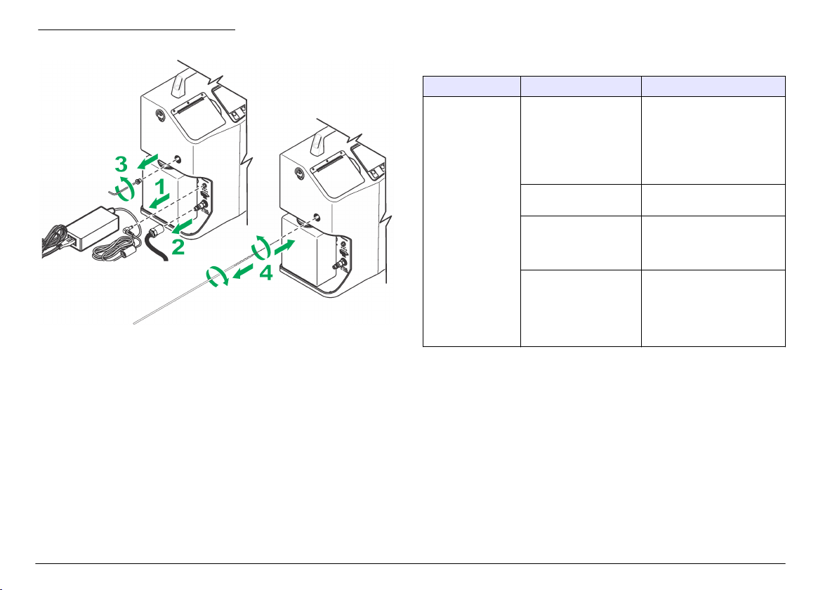
Figura 6 Desobstrucción del sensor
Calibración
Devuelva el instrumento anualmente para calibrarlo. La fecha de
calibración se muestra en la pegatina de calibración localizada en la
placa de serie dentro de la puerta del lado izquierdo (detrás del
contenedor de residuos). Cada instrumento se calibra en fábrica.
Solución de problemas
Si necesita ayuda con problemas potenciales, consulte la Tabla 7 y la
Tabla 8.
Si el programa no funciona correctamente y debe restablecer la
configuración predeterminada del instrumento, mantenga pulsada la
tecla F4 mientras se reinicia la alimentación.
Nota: De este modo, borrará todo el contenido del buffer y todas las variables de
funcionamiento se restablecerán con la configuración de fábrica. Se mostrarán un
mensaje predeterminado y el número referencia del firmware conforme el
instrumento vuelve a inicializar sus sistemas.
Tabla 7 Errores críticos
Error Posible causa Solución
Flow controller
failure (Error del
controlador de flujo)
La unidad no puede
encontrar el interruptor
HOME (Inicio) en el
controlador de flujo
durante la inicialización
del sistema o al final del
análisis de una muestra.
El controlador de flujo no
funciona correctamente.
Hay aire atrapado en el
tubo hidráulico interno.
(solo PODS)
No se purgó el
instrumento antes de que
se produjera un cambio
en la viscosidad del
fluido de muestra. (solo
PODS)
Vuelva a iniciar el instrumento.
Póngase en contacto con el
servicio de asistencia técnica.
Retire el aire del tubo
hidráulico interno, incluido el
puerto de limpieza, con un
fluido limpio.
Limpie el sistema con un fluido
nuevo.
60 Español
Page 61

Tabla 7 Errores críticos (continúa)
Error Posible causa Solución
Flow regulation
failure (Error de
regulación del flujo)
La presión externa
disminuyó durante el
análisis de la muestra.
No se purgó el
instrumento antes de que
se produjera un cambio
en la viscosidad del
fluido de muestra.
La cantidad de fluido de
muestra no es suficiente.
Se ha producido un
intento de purgar el
sistema con la descarga
de un fluido. (Solo
GlyCount)
Asegúrese de que la fuente de
aire externa está estable y
fijada en aproximadamente
100 psi. Asegúrese de que no
existen fugas en la junta tórica
de la cubeta de muestreo.
Purgue el instrumento.
Añada más fluido de muestra.
Purgue el instrumento con la
descarga de un fluido.
Asegúrese de que el fluido de
muestra permanece en la ruta
de flujo.
Tabla 7 Errores críticos (continúa)
Error Posible causa Solución
Low flow rate,
possible high
viscosity (Caudal
bajo, posible
viscosidad alta)
Hydraulic pressure
for online sampling
is not sufficient (La
presión hidráulica
del muestreo en
línea no es
suficiente).
Presión alta Se ha producido un error
La presión externa
disminuyó durante el
análisis de la muestra.
No se purgó el
instrumento antes de que
se produjera un cambio
en la viscosidad del
fluido de muestra.
La viscosidad del fluido
de muestra es
demasiado alta. (solo
PODS)
No se quitó el tapón del
tubo de recogida.
La fuente de presión
hidráulica no es
suficiente.
en el regulador hidráulico
interno o el valor del
ajuste se encuentra fuera
de los límites de
tolerancia.
Asegúrese de que la fuente de
aire externa está estable y
fijada en aproximadamente
100 psi. Asegúrese de que no
existen fugas en la junta tórica
de la cubeta de muestreo.
Purgue el instrumento.
Disminuya el caudal o diluya la
muestra con un fluido
adecuado, limpio, filtrado y
miscible que reducirá la
viscosidad de la muestra al
rango del contador
(10–424 cSt).
Quite el tapón.
Asegúrese de que la presión
del fluido es superior a 40 psi
durante todo el período de
análisis de la muestra.
Asegúrese de que no existen
fugas en la junta tórica del
adaptador en línea.
Póngase en contacto con el
servicio de asistencia técnica.
Español 61
Page 62

Tabla 7 Errores críticos (continúa)
Error Posible causa Solución
Presión baja La fuente de presión
Pressure dropped
to a level that is not
sufficient (La
presión ha caído a
un nivel
insuficiente).
externa no es suficiente.
El tapón del tubo de
recogida está instalado.
La presión externa
disminuyó durante el
análisis de la muestra.
La viscosidad del fluido
de muestra es
demasiado alta. (solo
PODS)
Se ha producido un error
en el regulador hidráulico
interno o el valor del
ajuste se encuentra fuera
de los límites de
tolerancia.
Asegúrese de que la fuente de
aire externa está estable y
fijada en aproximadamente
100 psi. Disminuya el caudal,
especialmente con fluidos de
alta viscosidad. Asegúrese de
que no existen fugas en la
junta tórica de la cubeta de
muestreo.
Quite el tapón del tubo de
recogida.
Asegúrese de que la fuente de
aire externa está estable y
fijada en aproximadamente
100 psi. Disminuya el caudal,
especialmente con fluidos de
alta viscosidad. Asegúrese de
que no existen fugas en la
junta tórica de la cubeta de
muestreo.
Disminuya el caudal o diluya la
muestra con un fluido
adecuado, limpio, filtrado y
miscible que reducirá la
viscosidad de la muestra al
rango del contador
(10–424 cSt).
Póngase en contacto con el
servicio de asistencia técnica.
Tabla 8 Errores no críticos
Error Posible causa Solución
SNSR FLOW CELL
ERROR (Error en
la celda de flujo del
sensor)
El área de visualización de
la celda del sensor está
obstruida y el detector no ve
la luz del láser.
La cantidad de fluido de
muestra no es suficiente.
El sensor no está calibrado
correctamente. Este hecho
da lugar a una señal baja.
La muestra está
contaminada con agua o
presenta un nivel alto de
contaminación por
partículas.
Se ha producido un error en
el sistema electrónico del
sensor o el láser. (Solo
GlyCount)
Limpie la celda siguiendo el
procedimiento descrito en
la sección Retirada de las
obstrucciones del sensor
de flujo en la página 59.
Añada más fluido de
muestra.
Devuelva la unidad a la
fábrica para calibrarla o
repararla.
Retire el agua o pruebe con
otra muestra. Si la muestra
está muy contaminada,
diluya la muestra.
Devuelva la unidad a la
fábrica para calibrarla o
repararla.
62 Español
Page 63

Índice
Informações adicionais
na página 63
Especificações na página 63
Informações gerais na página 64
Instalação na página 67
Inicialização na página 69
Interface do usuário e navegação
na página 69
Operação na página 73
Manutenção na página 77
Solução de problemas na página 80
Informações adicionais
Você poderá encontrar informações adicionais no website do fabricante.
Especificações
As especificações estão sujeitas a alterações sem aviso prévio.
Especificação Detalhes
Dimensões (C x L x A) 18.5 x 33.0 x 40.0 cm (7.3 x 12.5 x 15.7 pol.)
Peso 9.3 kg (20.5 lb)
Número de canais 8
Tamanho dos canais ISO-MTD 4, 4.6, 6, 9.8, 14, 21.2, 38, 68 μm
ACFTD ~1, 2, 5, 10, 25, 50, 100 μm
Vazão 15 a 50 ml/min (automático/manual)
Fonte de luz Laser de classe 3B, 810-852 nm, máximo de
Calibração ISO MTD (com base no ISO 11171)
Eficiência da contagem JIS B9925:1997
Limite de concentração 20.000 partículas por ml @ 5% de coincidência
50 mW
ISO 11171 completo - opcional
de perda (por ISO 11171)
30.000 partículas/ml @ 10% de coincidência
Especificação Detalhes
Volume de amostra 3 execuções (média) de 5, 10 ou 20 ml/execução
Faixa de temperatura do
fluido
Temperatura medida do
fluido
Faixa de viscosidade 10 a 424 cSt (59 a 2000 SUS)
Materiais molhados Alumínio, aço inoxidável, safira, PTFE e Aflas
Classificação de limpeza ISO 4406-1991, ISO 4406-1999, NAS 1638, MIL-
Armazenamento de dados registros de 500 amostras
comunicação serial de
entrada/saída
Altitude 2000 m (6561,7 pés)
Certificações CE
Funcionamento da garrafa
Volume de purga 15 a 30 ml (automático/manual)
Cartucho CO2, susbtituível, recarregável
Tempo de funcionamento 60 amostras (garrafa de amostra de 120 ml)
Ar comprimido 620 a 758 kPa (90 a 100 psi; 6,2 a 7,6 bar) de
Pressão do fluido 40 a 5000 psi (2,75 a 345 bar)
Energia
Entrada DC 24 VDC, máximo de 2 A
(programável)
0 a 90 °C em temperatura ambiente de 25 °C
(32 a 194 °F em 77 °F)
0 a 100 °C, ±0,5 °C (32 a 212 °F, ±0,9 °F)
Para mensurar a viscosidade, a faixa de
viscosidade é de 10 a 424 cSt ±20% do valor.
®
-STD-1246C, SAE AS 4059, NAVAIR 01-1A-1
RS232
Programável
Programável, tempo de espera e número de
amostra
limpeza, seco
Português 63
Page 64

Especificação Detalhes
Adaptador AC Universal 100–240 VAC, 50–60 Hz, 60 W
Bateria recarregável Níquel-metal-hidreto
Tempo de funcionamento 100 amostras ou 4 horas contínuas
Tempo de recarga 2.5 horas
Ambiente
Ambiente operacional 0 °C a 55 °C (32 °F a 131 °F); 5 a 95% de
Armazenamento -40 °C a 70 °C (-40 °F a 158 °F); acima de 98%
umidade relativa, sem condensação
de umidade relativa, sem condensação
Informações gerais
Em hipótese alguma o fabricante será responsável por danos diretos,
indiretos, especiais, incidentais ou consequenciais resultantes de
qualquer defeito ou omissão neste manual. O fabricante reserva-se o
direito de fazer alterações neste manual e nos produtos aqui descritos a
qualquer momento, sem aviso ou obrigação. As edições revisadas
podem ser encontradas no site do fabricante.
Informações de segurança
A V I S O
O fabricante não é responsável por quaisquer danos devido ao uso ou aplicação
incorreta deste produto, incluindo, sem limitação, danos diretos, acidentais ou
consequenciais, e se isenta desses danos à extensão total permitida pela lei
aplicável. O usuário é unicamente responsável por identificar riscos críticos de
aplicação e por instalar os mecanismos apropriados para proteger os processos
durante um possível mau funcionamento do equipamento.
Leia todo o manual antes de tirar da embalagem, montar ou operar esse
equipamento. Preste atenção a todas as declarações de perigo e
cuidado. Caso contrário, o operador poderá sofrer ferimentos graves ou
o equipamento poderá ser danificado.
Certifique-se de que a proteção oferecida por este equipamento não
seja afetada. Não use nem instale este equipamento de nenhuma outra
forma além da especificada neste manual.
Uso de informações de risco
P E R I G O
Indica uma situação potencial ou iminentemente perigosa que, se não for
evitada, resultará em morte ou lesão grave.
A D V E R T Ê N C I A
Indica uma situação potencialmente perigosa que, se não for evitada, pode
resultar em morte ou ferimento grave.
Indica uma situação potencialmente perigosa que pode resultar em ferimento
leve a moderado.
Indica uma situação que, se não evitada, pode causar danos ao instrumento.
Informações que necessitam de uma ênfase especial.
C U I D A D O
A V I S O
Avisos de precaução
Leia todas as etiquetas e rótulos fixados no instrumento. Caso não
sejam observadas, podem ocorrer lesões pessoais ou danos ao
instrumento. Se for observado algum símbolo no instrumento, haverá
uma declaração de cuidado ou perigo no manual.
64 Português
Page 65

Este símbolo, se observado no instrumento, diz respeito ao manual
de instruções para operação e/ou informações de segurança.
Os equipamentos elétricos marcados com este símbolo não podem
ser descartados em sistemas de descarte (lixo) públicos europeus
após 12 de agosto de 2005. Em conformidade com as
regulamentações nacionais e locais européias (Diretiva UE
2002/96/EC), os usuários de equipamentos elétricos devem devolver
seus equipamentos usados para o fabricante para descarte, sem
ônus para o usuário.
Observação: Para o envio de equipamento para reciclagem, entre em contato
com o fabricante ou fornecedor do equipamento para obter instruções sobre o
envio de sucata de equipamento, acessórios elétricos fornecidos pelo fabricante
e todos os itens auxiliares para um descarte adequado.
Este símbolo indica a necessidade de uso de óculos de proteção.
Produto a laser Classe 1
Este instrumento é classificado como um produto a laser Classe 1. Este
produto está em conformidade com as normas IEC/EN 60825-1:2007 e
21 CFR 1040.10, exceto para desvios de acordo com o Laser Notice No.
50, de 24 de junho de 2007.
Número de Acesso a FDA EUA 9912262-006. Este produto contém
laser classe 3B de 50 mW e 810-852 nm que não é mantido pelo
usuário.
Certificação
Canadian Radio Interference-Causing Equipment Regulation
(Regulamentação para equipamentos de rádio causadores de
interferência do Canadá), IECS-003, Classe A:
Os registros de testes de comprovação encontram-se com o fabricante.
Este aparelho digital Classe A atende a todos os requisitos de
regulamentações canadenses sobre equipamentos que causam
interferências.
Cet appareil numèrique de classe A répond à toutes les exigences de la
réglementation canadienne sur les équipements provoquant des
interférences.
FCC parte 15, limites Classe "A"
Os registros de testes de comprovação encontram-se com o fabricante.
O dispositivo está em conformidade com a Parte 15 das Regras da
FCC. A operação está sujeita às seguintes condições:
1. O equipamento não deve causar interferência prejudicial.
2. O equipamento deve aceitar todas as interferências recebidas,
inclusive interferências que podem causar funcionamento
indesejado.
Alterações ou modificações a este equipamento não aprovadas
expressamente pela parte responsável pela conformidade podem anular
a autoridade do usuário de operar o equipamento. Este equipamento foi
testado e está em conformidade com os limites de dispositivo digital
Classe A, de acordo com a Parte 15 das Regras da FCC. Esses limites
foram estabelecidos para proporcionar uma razoável proteção contra
interferências nocivas quando o equipamento for operado em ambientes
comerciais. Este equipamento gera, utiliza e pode irradiar energia de
rádiofrequência e, se não instalado e usado de acordo com o manual de
instruções, pode causar interferências prejudiciais às comunicações de
rádio. É provável que o funcionamento deste equipamento em área
residencial possa causar interferência indesejada, caso em que o
usuário será solicitado a corrigir a interferência por conta própria. As
seguintes técnicas podem ser usadas para reduzir problemas de
interferência:
1. Desconecte o equipamento de sua fonte de alimentação para
verificar se ele é ou não a origem da interferência.
2. Se o equipamento está conectado à mesma tomada do dispositivo
que está sofrendo interferência, conecte o equipamento a uma
tomada diferente.
3. Afaste o equipamento do dispositivo que estiver recebendo a
interferência.
4. Reposicione a antena de recebimento do dispositivo que está
sofrendo interferência.
5. Tente algumas combinações das opções acima.
Português
65
Page 66

Visão geral do produto
O Portable Oil Diagnostic System - PODS (Sistema de Diagnóstico
Portátil de Óleo - PODS) é utilizado para medir, manter e relatar a
contaminação do óleo. Isso é importante para que o funcionamento do
sistema hidráulico continue confiável. Este instrumento faz a análise de
fluidos pressurizados e lubrificantes nos modos de amostra de garrafas
ou online sem interromper o funcionamento das máquinas.
O instrumento é compatível com fluidos hidráulicos com base em
petróleo e em ester-fosfato (inclui MIL-H-5606 e Skydrol®). O
instrumento contém garrafas recarregáveis de CO 2 para uso em campo
e para a instalação da porta de ar comprimido para funcionamento
interno. Para visualizar o instrumento em formas diferentes, consulte a
Figura 1 e Figura 2.
Observação: Por motivos de restrição de envio nos EUA, os instrumentos são
enviados com garrafas de CO2 vazios.
Figura 1 Visão geral do produto
1 Porta da impressora 4 2 garrafas de CO
2 Tela 5 Adaptador de garrafa com amostra
3 Teclado
66 Português
Page 67

Figura 2 Vista lateral
Figura 3 Componentes do instrumento
1 Garrafa para resíduos 5 Manômetro
2 Alça 6 Porta de entrada de energia
3 Correia de ombro de ilhós em D 7 Porta RS232
4 Porta de limpeza 8 Porta de ar comprimido
Componentes do produto
Certifique-se de que todos os componentes foram recebidos. Consulte
Figura 3. Se houver itens ausentes ou danificados, entre em contato
imediatamente com o fabricante ou com um representante de vendas.
1 Instrumento 4 Cabo de alimentação 7 Papel de impressora
2 Adaptador de
alimentação CA
3 Frasco vazio de CO
(2)
5 Frasco de amostra
(10)
6 Chave Allen 9 Disco de software
2
(2)
8 Escova de limpeza
(2)
Instalação
A D V E R T Ê N C I A
Vários perigos. Somente pessoal qualificado deve realizar as tarefas
descritas nesta seção do manual.
Conectar pressão externa
Conecte o frasco de CO2 ou o ar comprimido à impressora para gerar
pressão externa.
Português
67
Page 68

Conecte o frasco de CO
Vários perigos. Somente pessoal qualificado deve realizar as tarefas
descritas nesta seção do manual.
Risco de explosão. Para o uso seguro do instrumento, obedeça às
precauções e instruções especificamente descritas.
Risco de lesão corporal. Os sistemas anexos podem conter alta
pressão. Pessoas qualificadas devem remover a pressão do sistema
antes de instalar ou remover o instrumento.
Perigo de incêndio. Não use agentes inflamáveis para limpar o
instrumento.
2
P E R I G O
P E R I G O
A D V E R T Ê N C I A
C U I D A D O
O frasco de CO2 contém gás comprimido sob alta pressão. Não
modifique este frasco de modo algum. Use apenas frascos de CO
fornecidos pelo fabricante. Somente use o frasco de acordo com as
2
instruções deste manual. Para armazenar e descartar o frasco, consulte
o texto no próprio produto.
Não exponha o frasco pressurizado a temperaturas extremas de 177 °C
(350 °F). Frascos expostos ao fogo ou aquecidos em temperaturas
extremas de 177 °C (350 °F) devem ser descartados. Deixe o frasco
esfriar antes de descartá-lo.
Mantenha a tampa de proteção nos frascos de CO2 que não estão mais
sendo usados.
Apenas pessoas treinadas devem instalar ou remover as válvulas.
Use apenas água e detergente neutro para limpar o cilindro. O uso de
soluções cáusticas de limpeza pode corroer as conexões de pressão ou
as paredes do tanque, causando liberação ou alívio de pressão.
Verifique se o adaptador do frasco está instalado corretamente antes de
iniciar a pressurização. Se não estiver instalado corretamente, o
adaptador do frasco se desprenderá da impressora e provocará
ferimentos pessoais e/ou danos a ela.
Devido a diversos regulamentos e normas de envio, os frascos de CO
fornecidos nos contêineres de remessa vêm vazios. Os frascos devem
2
ser abastecidos por um fornecedor de CO2 certificado.
A V I S O
Não remova nem cubra o rótulo do frasco.
Apenas pessoas com o treinamento adequado devem encher e transportar esse
frasco de acordo com os regulamentos de abastecimento de frascos com gás
comprimido da jurisdição local.
O adaptador do frasco é um recipiente de pressão usado na entrega de
amostras pela impressora. É importante que ele seja instalado na posição de
travamento antes da amostragem. O adaptador do frasco deve estar alinhado à
impressora e permanecer na posição de travamento.
A V I S O
A V I S O
Item a recolher:
• Lubrificante limpo (para facilitar o uso e evitar danos ao anel O)
1. Verifique se há danos nas roscas e no anel O.
2. Gire o frasco no sentido horário até a porta CO2. Com a rotação do
frasco até a porta CO2, a válvula do frasco é aberta e a pressão é
aplicada à impressora. Quando isso ocorre, fica difícil girar o frasco.
3. Gire o frasco em ¼ até que ele pare. Caso o CO2 seja liberado pelas
roscas do frasco durante a pressurização, remova o frasco de CO2 e
verifique se há danos no anel O.
Conectar a fonte de ar comprimido
A D V E R T Ê N C I A
Risco de lesão corporal. Os sistemas anexos podem conter alta
pressão. Pessoas qualificadas devem remover a pressão do sistema
antes de instalar ou remover o instrumento.
68 Português
Page 69

A fonte de ar comprimido deve estar limpa, seca e entre 620 e 758 kPa
(90 a 100 psi; 6,2 a 7,6 bar).
1. Caso o tipo do bico de ar comprimido seja inadequado, instale um
novo. É necessária uma conexão com NPT macho de 1/8 pol.
2. Verifique se as roscas da porta estão limpas.
3. Conecte o ar comprimido na impressora e aperte.
Conectar os cabos de comunicações
A impressora tem instalada uma porta de comunicações RS232. Use
essa porta e se comunique com um computador para fins de operação
remota, análise e aquisição de dados.
• Taxa de transmissão: 9.600
• Bits de dados: 8
• Paridade: nenhuma
• Bits de parada: 2
Caso o computador ou o terminal tenha uma porta serial de nove pinos
com um conector macho, use um cabo serial padrão que tenha uma
extremidade macho e uma fêmea. A impressora já está configurada
como DCE (Data Communication Equipment, Equipamento de
comunicação de dados). Não é necessário um cabo null-modem.
Conectar a fonte de alimentação externa
Ao usar uma fonte de alimentação externa, siga as instruções em Trocar
a bateria na página 78.
Inicialização
Verificação de teste automático e inicialização
Pressione POWER (Alimentação) para exibir a tela de inicialização: ela
exibirá o número de série e o nível de revisão do firmware da
impressora. Nessa etapa, a impressora verifica se há problemas em
seus sistemas internos. Se houver algum problema, a impressora
exibirá uma mensagem de erro. Consulte Solução de problemas
na página 80.
Interface do usuário e navegação
Descrição do teclado numérico
Figura 4 exibe os recursos inclusos no teclado.
Figura 4 Recursos do teclado
1 Teclas de função 6 POWER (Força)
2 ALIMENTAÇÃO DE LINHA 7 Luz do STATUS DE
CARREGAMENTO DA BATERIA
3 CANCELAR 8 Teclas alfanuméricas
4 START (INICIAR) 9 Teclas de navegação
5 Tela
Recurso Descrição
Função teclas Pressione a tecla de função para ativar um
atributo na tela.
ALIMENTAÇÃO DE LINHA Move o papel da impressora.
Português 69
Page 70

Recurso Descrição
CANCELAR Cancela um teste de amostra/uma função de
START (INICIAR) Inicia um teste de amostra.
Tela Exibe as informações sobre o processo de
POWER (Força) Inicia e interrompe a alimentação
Luz do STATUS DE
CARREGAMENTO DA
BATERIA
Teclas alfanuméricas Adiciona letras e números ao programa. Para
Teclas de navegação Seleciona variáveis operacionais e move o cursor
programação e mantém a seleção anterior.
contagem, códigos de erro, resultados do teste de
amostra e o status das variáveis operacionais.
Exibe o modo de operação atual do sistema de
carregamento. Para obter mais informações,
consulte Trocar a bateria na página 78.
obter mais informações, consulte Definir as
variáveis operacionais na página 70.
para a direita/esquerda.
Visualizar os parâmetros do menu de status
Pressione F3 (SYS) no menu principal para acessar o menu de status
do sistema. Tabela 1 exibe diversos parâmetros do sistema que são
medidos pela impressora. Esses parâmetros do sistema exibem
informações práticas, diagnóstico e solução de problemas.
Tabela 1 Parâmetros do sistema
Parâmetro Descrição
Fonte de
alimentação
Temperatura
interna
Status da
impressora
Mostra se a impressora está conectada a uma fonte de
alimentação externa ou se está sendo operada com uma
bateria interna. Quando uma fonte de alimentação externa é
usada, o ícone de bateria mostra que a bateria interna está
sendo controlada pela fonte de alimentação externa.
Quando a bateria interna é usada, o ícone de bateria exibe a
capacidade relativa de tensão restante da bateria. A taxa útil
de tensão da bateria da impressora é de 11,5 a 13,8 volts.
Capacidades inferiores a essa taxa são considerados
mínimos, portanto carregue a bateria antes de continuar a
operação.
Exibe apenas a temperatura dentro do compartimento da
impressora. Essa medição informa se a temperatura está
muito quente ou fria para realizar um teste de amostra.
Exibe diferentes erros ou condições de status da impressora
interna. Se a impressora estiver funcionando, a condição
NORMAL será exibida. Uma mensagem de erro é exibida
quando há algum problema.
Para obter uma explicação sobre esses códigos de erro, consulte
Solução de problemas na página 80.
Definir as variáveis operacionais
As variáveis operacionais ficam localizadas no menu Setup
(Configuração). Consulte Tabela 2 – Tabela 6. Para definir uma variável
operacional:
70
Português
1. Pressione F1 (SETUP) para acessar o menu Setup (Configuração).
2. Pressione o número no teclado numérico que corresponde ao
número à esquerda da variável que será programada.
Page 71

3. Pressione F1 (PRG) e use as teclas de navegação para selecionar a
configuração adequada ou use o teclado para inserir números, letras
ou símbolos.
Para adicionar letras:
a. Pressione a tecla numérica que contém a letra a ser usada em
sequência.
b. Pressione uma vez para digitar o número, duas vezes para a
primeira letra, três vezes para a segunda letra etc. O intervalo
entre o pressionamento das teclas informa se o caractere atual
ou o próximo caractere foram selecionados.
Para adicionar símbolos:
a. Pressione a tecla de função que representa o símbolo a ser
usado.
b. Pressione F1 para dar espaço, F2 para inserir uma barra, e F3
para digitar um ponto.
4. Pressione F4 para aceitar a nova configuração ou CANCEL
(Cancelar) para retornar ao menu Setup (Configuração) e manter a
seleção anterior.
5. Para visualizar os resultados do teste em outro Padrão, Viscosidade
ou Temperatura, defina as variáveis e veja/imprima os resultados do
teste do buffer. Consulte Resultados do teste na página 76.
Tabela 2 Menu Setup
Variável Descrição
SAMPLE
LABEL (Rótulo
de amostra)
MODE (Modo) Método de amostragem (BOTTLE, ONLINE ou FILTER)
Exibe um segundo menu: Sample Text (Texto da amostra)
Nesse menu, defina os itens a seguir:
• SAMPLE LABEL “SAMPLE NAME”: o nome das amostras
inserido pelo usuário. O limite dos rótulos de amostra é de
10 caracteres. Para cada rótulo de amostra, há uma extensão
de contagem automática que permite até 500. Essa extensão é
redefinida como 1 sempre que um novo rótulo de amostra é
programado, reinserido ou excede a contagem de 500.
• REMARKS: observações feitas pelo usuário em qualquer
rótulo de amostra adicional (se necessário). Essas
observações opcionais se tornam parte do registro de qualquer
amostra concluída. As observações dos registros obtidos no
buffer de amostra podem ser revisadas ou reeditadas
conforme necessário. O limite de observações da amostra é de
10 caracteres em qualquer uma das três linhas. Todas as
observações existentes são exibidas nos relatórios de
amostras impressos.
[Frasco, Em linha ou Filtro]
Se BOTTLE (Frasco) for selecionado ou acessado novamente,
uma segunda tela será exibida e permitirá a definição da
seguinte variável.
• PURGE VOL: volume do fluido que passa pela impressora
para eliminar qualquer contaminação antes da coleta de
amostras (15 a 30 ml).
Se ONLINE (Em linha) for selecionado ou acessado
novamente, uma segunda tela será exibida e permitirá a
definição da seguinte variável.
• NUM SAMPLES: número de amostras que são coletadas
durante o período de amostragem (1 a 500).
• HOLD TIME: atraso desde a conclusão de uma amostra até o
início da próxima. Se for definido como 00:00, será
estabelecido um atraso de ao menos 5 segundos (hh:mm).
• PURGE VOL: o volume do fluido que passa pela mangueira
hidráulica e a unidade para eliminar qualquer contaminação
antes da coleta de amostras. Quanto maior for a mangueira
hidráulica, maior deverá ser o volume do líquido de limpeza
(15 a 999 ml).
Português 71
Page 72

Tabela 2 Menu Setup (continuação)
Variável Descrição
STD (Padrão) Controla o formato padrão para exibir os resultados da amostra
VOL (Volume) Volume do fluido que circula três vezes durante uma amostra
FLOW (Fluxo) Define as seleções da taxa de fluxo entre 15 e 50 ml/min ou o
PRINT
(Imprimir)
CONTRAST
(Contraste)
(ISO(C), ISO, NAS(C), NAS, NAV(C), NAV, SAE(C), SAE, MIL,
P/10 ml ou P/1 ml).
(Volume/CICLO). A amostragem do modo BOTTLE (Frasco) é
limitada (5, 10 ou 20 ml por CICLO).
modo AUTO (Automático). O modo AUTO (Automático) utiliza
automaticamente a melhor taxa de fluxo para as condições da
amostra atual.
Ativa/desativa a impressora para que ela não imprima
automaticamente ao concluir uma amostra. A opção SETUP
(Configuração) imprime a configuração atual da impressora
(ENBL, DSBL ou SETUP).
Use as teclas de navegação para controlar o contraste da tela.
Tabela 3 Tela: PG 2
Variável Descrição
LANG (Idioma) Exibe o idioma usado na operação e no controle da
VISC (Viscosidade) Controla as unidades que exibem a viscosidade (cSt,
TEMP Exibe as unidades de temperatura (°C ou ºF).
PRESS (Pressão) Exibe as unidades de pressão (BAR ou PSI).
DISPL (Tela) Controla o brilho do fundo da tela: iluminação clara
impressora (Inglês, francês, alemão, espanhol e
italiano).
mm2/s ou SUS).
(Normal) ou iluminação escura (Inversa) (NORM ou
REV).
Tabela 3 Tela: PG 2 (continuação)
Variável Descrição
BKLT (Iluminação de
fundo)
BEEP (Bipe) Controla o som do bipe quando uma tecla é
BSAVE (Economia de
bateria)
Controla a iluminação de fundo da tela LCD. Se o modo
AUTO (Automático) for selecionado, a luz de fundo
apagará após 5 minutos de inatividade (ON, OFF ou
AUTO).
pressionada (KEY ou DSBL).
Recurso de economia da bateria. Se essa função
estiver ativada, a impressora desligará
automaticamente após 15 minutos de inatividade
(Estado ocioso) ((ENBL (Ativado) ou DSBL
(Desativado)).
Tabela 4 Tela: SIZ
Menu com tamanho programável. Quando o MODE (Modo) é definido como
P/1 ml ou P/10 ml, o menu PG2 fica disponível para qualquer um dos oito canais
de tamanho a ser programados. O limite do programa de tamanho mínimo e
máximo é de 4,0 a 68,0 μm. O tamanho deve ser programado em ordem
crescente, do menor tamanho no canal 1 até o maior tamanho no canal 8.
Observação: Se necessário, use F2 (DEFAULT) para restaurar a configuração padrão de
fábrica de todos os tamanhos.
Tabela 5 Tela: I/O
Variável Descrição
UNIT_ID Define um endereço de dispositivo exclusivo que é usado na
CNTRL Defina como LOCAL quando a impressora for operado manualmente.
comunicação serial do protocolo MODBUS da impressora (01 a 99).
Defina como REMOTE (Remoto) quando um programa do
computador operar e controlar a amostragem da impressora. Defina
como DOWNLOAD apenas quando um programa do computador
obtiver os registros do buffer de amostra. A configuração dessa
variável também pode ser alterada automaticamente através do
protocolo serial MODBUS (LOCAL, REMOTE ou DOWNLOAD).
72 Português
Page 73

Tabela 6 Tela: CLK
Variável Descrição
TIME (TEMPO DE
RESPOSTA)
DATE (DATA) Data atual (Mês/dia/ano)
Horário atual no formato de 24 horas
(Horas/minutos/segundos)
Operação
A D V E R T Ê N C I A
Risco de exposição a produtos químicos. Obedeça aos procedimentos
de segurança laboratoriais e use todos os equipamentos de proteção
individual adequados aos produtos químicos que estão sendo
manipulados. Consulte as planilhas de dados de segurança de
(MSDS/SDS) atuais para verificar os protocolos de segurança.
Risco de exposição a produtos químicos. Descarte produtos químicos
e dejetos de acordo com as regulamentações locais, regionais e
nacionais.
Procedimento para coletar uma amostra
Use técnicas adequadas para coletar uma amostra. É importante coletar
uma amostra característica do nível de contaminação do sistema que
está sendo testado. Colete uma amostra usando uma fonte com fluido
variável.
Observação: Se a amostra for coletada de um fluxo com variação lenta, poderá
se tornar uma amostra não característica. Deixe o sistema funcionando por ao
menos 30 minutos antes de coletar a amostra.
Observação: O modo de Filtro não está mais ativo. Use um dos outros modos
para coletar uma amostra.
Ao completar uma série de testes, ainda haverá um pouco de amostra
dentro da impressora. É preciso realizar a limpeza interna da impressora
com um fluido que não contamine a próxima amostra. Para realizar a
limpeza interna da impressora:
C U I D A D O
1. Use o mesmo tipo de fluido conforme planejado para a próxima
amostra. Não misture os tipos de fluido. Se outros tipos de fluido
forem utilizados, a incompatibilidade de fluidos causará erros de
amostragem.
2. Se uma operação em linha for realizada, a limpeza interna da
impressora será feita com o fluido a ser testado. Para realizar a
limpeza interna adequada da impressora, o volume do líquido deve
ser equivalente a quase o dobro do volume interno da mangueira
hidráulica que conecta a impressora ao sistema que será testado.
3. Realize a limpeza interna total antes de coletar uma amostra para
garantir precisão na medição da amostra. Para realizar a limpeza
interna da impressora, consulte Realize a limpeza da impressora no
modo de frasco na página 74 ou Realizar a limpeza interna da
impressora no modo em linha na página 74.
Observação: A limpeza interna em excesso pode causar a pré-obstrução dos
filtros.
Preparar coleta de amostra com um frasco
Fontes comuns de contaminação adicionadas acidentalmente a
amostras de fluido são provenientes de partículas aéreas, de frascos e
tubos de recolhimento. Use apenas frascos de amostra limpos e
mantenha-os sempre cobertos.
Erros de amostra ocorrem devido ao excesso de bolhas de ar e
contaminação de água. Ambas são consideradas partículas. Para
remover as bolhas de ar, aplique vácuo à amostra em uma câmera de
vácuo ou deixe-a em banho ultrassônico por alguns segundos.
Como as partículas acumulam no fundo do frasco de amostra após
alguns minutos, é preciso agitar a amostra para suspendê-las
novamente e retirar os gases para remover as bolhas.
As amostras altamente contaminadas afundam o sensor e tornam
inválidos os dados da contagem de partículas. O limite da impressora é
de 20.000 partículas por ml a 5% de perda por coincidência (de acordo
com o ISO11171) e 30.000 partículas por ml a 10% de perda por
coincidência de fluido para um tamanho específico. Se a contaminação
for suspendida em uma amostra de fluido, a amostra conterá
concentrações além dos limites de saturação da impressora. Uma
pessoa comum só consegue ver partículas maiores do que 40 μm.
Português
73
Page 74

Use a bomba de vácuo de amostragem de fluido para retirar o fluido de
amostra dos reservatórios.
1. Corte um pedaço de tubo limpo com extensão desde o fluido do
reservatório até um ponto acessível da parte externa do reservatório.
2. Conecte um frasco de amostra limpo à bomba de vácuo de
amostragem de fluido (VP633001). Instale uma extremidade do tubo
na bomba para que ele se estenda até o frasco de amostra e aperte
a saliência.
3. Instale a outra extremidade do tubo no reservatório. Não contamine
a extremidade do tubo.
4. Use a bomba para encher o frasco de amostra até o nível adequado.
5. Desconecte o frasco de amostra da bomba.
6. Coloque a tampa até que a amostra esteja pronta para teste.
Preparar medição em linha
Alguns locais adequados para a medição em linha são:
• Fluxo ascendente do filtro de alta pressão (condição pós-bomba)
• Fluxo ascendente do filtro de retorno (condição pós-sistema)
• Fluxo ascendente do filtro de desvio (condição do tanque)
1. Desconecte a mangueira hidráulica que conecta a impressora ao
sistema que será testado.
2. Remove o fluido que já foi testado.
3. Defina o volume do líquido de limpeza com o dobro do volume
interno da mangueira hidráulica.
4. Consulte um especialista em aplicação antes da instalação da porta.
Observação: Não instale nenhum outro dispositivo de controle de fluido na
mangueira hidráulica de amostra ou na porta de teste do sistema. Esses
dispositivos fazem bolhas e criam capturadores de partículas que causam
erros de amostra.
Realize a limpeza da impressora no modo de frasco
Observação: Se o volume limpo exceder a quantidade de fluido do adaptador do
frasco, a pressão pneumática será distribuída pela impressora e sairá pelo orifício
de drenagem. Isso cria bolsas de ar no sistema hidráulico e causa erros de
amostragem.
1. Verifique se o frasco de CO2 e o ar comprimido estão conectados à
impressora e se o medidor de pressão exibe 90 a 110 psi (6,2 a
7,6 bar).
2. Gire o adaptador do frasco no sentido anti-horário para desconectá-
-lo da impressora.
3. Encha um frasco de amostra com o fluido que será usado na
limpeza interna.
4. Coloque o frasco de amostra no adaptador e conecte-o à
impressora.
5. No menu principal, pressione F4 para acessar o menu de limpeza
interna.
6. Pressione INICIAR.
7. Pressione F1 (SOL ON). O adaptador do frasco é pressurizado e o
fluido começa a sair pelo orifício de drenagem. A quantidade de
fluido usada para a limpeza interna é exibida na tela.
8. Após o escorrimento do fluido, pressione CANCEL (Cancelar) para
interromper o fluido e retornar ao menu principal.
Realizar a limpeza interna da impressora no modo em linha
1. Conecte o adaptador em linha à impressora. Mova o tubo de
recolhimento até o orifício no centro do adaptador e gire o adaptador
no sentido horário, até travar o tubo de recolhimento.
2. Conecte uma mangueira hidráulica com uma rosca da mangueira de
teste Minimess® ao adaptador em linha.
3. Conecte a outra extremidade da mangueira hidráulica ao sistema
que será testado.
4. No menu principal, pressione F4 para acessar o menu de limpeza
interna.
5. Pressione INICIAR. O fluido sai pelo orifício de drenagem, e a
quantidade de fluido é exibida na tela.
74
Português
Page 75

6. Após o escorrimento do fluido, pressione CANCEL (Cancelar) para
interromper o processo de limpeza interna e retornar ao menu
principal.
Observação: Se a alimentação for interrompida durante a limpeza interna do
sistema, o controlador de fluxo interno permanecerá aberto e permitirá que o
fluido flua. Sempre cancele o processo de limpeza interna e aguarde alguns
segundos antes de desligar a impressora.
Observação: O sistema permanece pressurizado após a remoção da fonte de
pressão. Para eliminar a pressão do sistema, remova a fonte de pressão e
pressione START (Iniciar), ou selecione "SOL ON” e “SOL OFF” até que o
medidor de pressão leia 0 psi.
Compatibilidade de fluido
A impressora é compatível com a maioria dos fluidos baseados em
petróleo e éster de fosfato dentro das variações de temperatura e
viscosidade especificadas. Em caso de dúvida quanto à compatibilidade
de um fluido, compare-a com a lista de materiais umedecidos inclusa no
Especificações na página 63 Caso não haja compatibilidade, envie uma
solicitação a um representante do fabricante local para obter uma
recomendação sobre o uso do fluido na impressora.
A V I S O
Os componentes internos dessa impressora não são compatíveis com água. A
água provoca danos e mau funcionamento na impressora. A impressora só é
compatível com fluidos que contêm propriedades lubrificantes.
Coletar uma amostra no modo de frasco
1. Coloque um fluido de amostra no adaptador do frasco.
2. Conecte o adaptador à impressora.
3. No menu principal, pressione F1 (SETUP) (Configuração) para
acessar o menu de configuração.
4. Defina o modo de amostragem como BOTTLE (Frasco) e verifique
se as outras variáveis operacionais estão programadas conforme
necessário. Para obter mais informações, consulte Especificações
na página 63.
5. Verifique se o frasco de CO2 ou o ar comprimido está conectado à
impressora.
6. Verifique se há entre 90 e 110 psi (6,2 a 7,6 bar) no medidor de
pressão. Devido às variações dos regulamentos, a pressão exibida
no medidor de pressão chega até 120 psi (8,3 bar) durante
condições sem fluxo. A pressão cai quando uma amostra é iniciada.
7. Gire o adaptador do frasco no sentido anti-horário para desconectá-
-lo da impressora.
8. Encha um frasco de amostra com o fluido que será testado.
9. Coloque o frasco no adaptador.
10. Conecte o adaptador de amostra à impressora.
11. Verifique se o compartimento de líquido sujo retém o fluido.
12. Pressione INICIAR. O processo de amostragem é iniciado.
Quando esse processo é concluído, os resultados do teste são
colocados no buffer, exibidos na tela e/ou impressos.
Coletar uma amostra no modo em linha
No modo em linha, uma amostra sai diretamente de um sistema
hidráulico. O CO2 ou as fontes de pressão externas de ar comprimido
não são usados nesse modo, porém permanecem conectados durante o
processo de amostragem.
1. No menu principal, pressione F1 (SETUP) (Configuração) para
acessar o menu de configuração.
2. Defina o modo de amostragem como ONLINE (Em linha) e defina o
programa com o número de ciclos, o tempo de retenção e o volume
do líquido de limpeza. O volume do ciclo de limpeza deve ser quase
o dobro do volume interno do tubo hidráulico que conecta a
impressora ao sistema.
3. Verifique se as outras variáveis operacionais estão programadas
conforme necessário. Para obter mais informações, consulte Definir
as variáveis operacionais na página 70.
4. Para conectar o adaptador em linha à impressora, insira o tubo de
recolhimento no orifício localizado no centro do adaptador e gire o
tubo no sentido horário, até travar o adaptador.
5. Conecte uma mangueira hidráulica com uma rosca da mangueira de
teste Minimess® ao adaptador em linha.
Português
75
Page 76

6. Conecte a outra extremidade da mangueira hidráulica ao sistema
que será testado.
7. Pressione INICIAR. O processo de amostragem é iniciado.
Quando esse processo é concluído, os resultados do teste são
colocados no buffer, exibidos na tela e/ou impressos.
Observação: Se a alimentação for interrompida durante a limpeza interna da
impressora, o controlador de fluxo interno permanecerá aberto e permitirá que
o fluido flua. Sempre cancele o processo de limpeza interna e aguarde alguns
segundos antes de desligar a impressora.
Resultados do teste
Os dados de contagem exibem o número de contagens por ciclo
individual e a média dos três ciclos. Um relatório de teste exibe:
• Tipo da amostra
• Número de série da unidade que coletou a amostra
• Data e horário em que a amostra foi coletada
• Volume por ciclo de amostra
• Vazão
• Viscosidade medida
• Temperatura medida do fluido
• Unidades de concentração
• Formato de limpeza mensurado
• Contagem de dados por tamanho de mícron
Para as informações do Padrão ISO, o volume do ciclo oferece o menor
nível do código de contaminação.
• Para um volume de ciclo de 5 ml, o menor nível do código ISO
informado é 03/03/03.
• Para um volume de ciclo de 10 ml, o menor nível do código ISO
informado é 02/02/02.
• Para um volume de ciclo de 20 ml, o menor nível do código ISO
informado é 01/01/01.
Para obter mais informações sobre esse assunto, consulte o ISO 4406,
"Força do fluido hidráulico - Fluidos - Código", para calcular o nível de
contaminação por partículas sólidas.
A temperatura exibida é a temperatura no final do circuito hidráulico
(dentro do controlador de fluxo). Ela não é uma medida da temperatura
do fluxo recebido. O circuito hidráulico tem massas térmicas que
influenciam a temperatura do fluido.
• Se a impressora estiver mais fria que o fluido, haverá uma queda de
temperatura do fluido durante a amostragem.
• Se a impressora estiver mais quente, haverá um aumento de
temperatura durante a amostragem do fluido.
Interpretação dos resultados: compare os resultados informados com as
faixas-alvo correspondentes do sistema que está sendo testado. Em
seguida, será possível tratar ou substituir o fluido.
Operação de buffer
Visualizar os conteúdos
1. Use o menu de buffer para visualizar os conteúdos de buffer:
• ÚLTIMA AMOSTRA: exibe os resultados da última amostra.
• BUFFER DE LISTA: exibe os oito nomes de amostras mais
recentes para a próxima revisão.
• BUFFER DE PESQUISA: pesquisa um nome de amostra
específico. Insira o nome completo ou parcial da amostra.
2. Após selecionar uma amostra, pressione as teclas de função
correspondentes para visualizar a amostra anterior ou seguinte. Os
conteúdos de buffer são exibidos na configuração programada atual.
3. Para exibir os resultados em outra configuração, altere as variáveis
operacionais para outra configuração e verifique novamente os
conteúdos de buffer.
76
Português
Page 77

Excluir ou imprimir dados
Use o menu de buffer para excluir ou imprimir conteúdos de buffer.
1. Pressione F2 (DEL BUF) para excluir todos os conteúdos de buffer.
A impressora exibe uma mensagem de confirmação e solicita a
confirmação ou o cancelamento da operação.
2. Pressione F3 (PRT BUF) para imprimir todos os conteúdos de buffer.
A impressora exibe uma mensagem de confirmação e solicita a
confirmação ou o cancelamento da operação.
3. Pressione F1 (DEL SMP) ou F2 (PRT SMP) no menu de contagem
média (AVG CNT) para excluir um imprimir um resultado de teste
individual. Quando uma seleção de amostra for exibida, o menu de
contagem média estará disponível.
Visualizar os dados de amostra
Quando uma seleção é feita, a impressora exibe as estatísticas dessa
amostra específica. Pressione a tecla de função de contagem média
(AVG CNT) para visualizar o lembrete dos dados de amostra.
Manutenção
P E R I G O
Vários perigos. Somente pessoal qualificado deve realizar as tarefas
descritas nesta seção do manual.
A V I S O
Cuidado para não entortar o tubo de recolhimento ou arranhar a extremidade
inferior em que a conexão de selo é feita. O dano pode causar vazamento ou
mau alinhamento com o adaptador em linha.
1. Limpe a impressora com uma escova de limpeza e uma solução de
limpeza com glicol.
2. Realize a limpeza interna da impressora.
Trocar o filtro
Para remover o filtro, consulte Figura 5.
A D V E R T Ê N C I A
Risco de lesão corporal. Jamais remova as tampas do instrumento.
Este é um instrumento com base em laser e o usuário correrá riscos
de se ferir se exposto ao laser.
Como limpar o instrumento
C U I D A D O
Perigo de incêndio. Não use agentes inflamáveis para limpar o
instrumento.
Português 77
Page 78

Figura 5 Remoção do filtro
Trocar a bateria
Alimente a impressora com:
• uma bateria interna recarregável
• uma fonte de alimentação externa
Com a bateria interna totalmente carregada, a impressora funciona em
ao menos 100 amostras antes de precisar carregá-la novamente. A
fonte de alimentação externa também é usada para carregar a bateria
interna. É possível usar a impressora durante o carregamento da bateria
interna.
Itens para coletar:
• Fonte de alimentação externa
• Cabo de alimentação
1. Conecte o cabo de alimentação à fonte de alimentação externa.
2. Conecte a outra extremidade do cabo de alimentação a uma tomada
elétrica.
3. Conecte a tomada da fonte de alimentação externa na impressora,
no local da porta de alimentação (localizada abaixo do medidor de
pressão).
4. Você ouvirá um "clique". Verifique se a luz do Status de
carregamento da bateria (localizada no teclado) está acesa. Essa luz
representa um dos três modos do status de carregamento:
Indicador Status
Verde contínua Carregando
Verde piscante Modo de manutenção
Vermelha contínua Falha ao carregar a bateria
78
Português
Adicionar papel de impressora
1. Abra a porta da impressora.
2. Coloque o papel na impressora para que ele saia pela parte inferior
do rolo.
Page 79

3. Com a impressora ligada, insira o papel na impressora e pressione
LINE FEED (Alimentação de linha). O papel é alimentado pela
impressora.
4. Dobre a parte solta do papel no rolo e insira-a no porta-papel.
5. Levante a parte solta do papel e feche a porta da impressora.
6. Remova o papel em excesso.
Observação: Caso o papel não esteja alinhado corretamente, levante a
alavanca ao lado esquerdo da impressora para elevar o carro da impressora.
Puxe o papel em linha reta e o alinhe. Abaixe o carro antes de operar a
impressora.
Remover as obstruções do sensor de fluxo
C U I D A D O
Risco de exposição a produtos químicos. Obedeça aos procedimentos
de segurança laboratoriais e use todos os equipamentos de proteção
individual adequados aos produtos químicos que estão sendo
manipulados. Consulte as planilhas de dados de segurança de
(MSDS/SDS) atuais para verificar os protocolos de segurança.
A V I S O
Se você exercer muita força, poderá danificar a escova ou possivelmente as
cubetas. Se a escova não penetrar a cubeta, remova-a e verifique se há danos
na ponta de limpeza.
Siga todas as etapas preventivas para evitar danos na impressora e
ferimentos pessoais.
Itens para coletar:
• Pano absorvente
• Chave Allen
• Escova de limpeza
3. Com um movimento giratório, empurre cuidadosamente a escova
para dentro da cubeta de fluxo.
4. Opere a impressora com o fluido limpo de amostra. Para eliminar o
ar preso no tubo de saída do líquido de limpeza:
a. Coloque um pano absorvente sobre a chave e solte levemente a
tampa da saída do líquido de limpeza durante o processo de
amostragem. O fluido e o ar saem rapidamente quando a tampa
está solta.
b. Continue o processo até que o ar pare de sair pelo orifício.
5. Aperte levemente a tampa do orifício de saída do líquido de limpeza.
Para evitar danos nas roscas, não aperte demais a tampa.
Figura 6 Remoção de obstruções do sensor
1. Coloque um pano absorvente sob a impressora para absorver o
líquido que sair pelo orifício. Consulte Figura 6.
2. Mantenha a escova dentro do orifício de saída do líquido de limpeza
até que haja resistência.
Calibração
Leve a impressora anualmente para calibrá-la. A data de calibração é
exibida no adesivo de calibração que fica localizado na placa de série
Português
79
Page 80

dentro da porta esquerda (atrás do container de lixo). Cada impressora
é calibrada na fábrica.
Solução de problemas
Para obter ajuda com possíveis problemas, consulte Tabela 7 e
Tabela 8.
Caso o programa não funcione ou seja preciso restaurar as
configurações padrão da impressora, mantenha pressionada a tecla F4
durante a inicialização.
Observação: Isso apaga todos os conteúdos de buffer e restaura todas as
configurações padrão de fábrica das variáveis operacionais. Uma mensagem
padrão e o número da peça do firmware são exibidos enquanto a impressora
inicializa seus sistemas novamente.
Tabela 7 Erros críticos
Error (Erro) Causa possível Solução
Falha no
controlador de fluxo
A unidade não conseguiu
encontrar o botão HOME
(Início) no controlador de
fluxo durante a
inicialização do sistema
ou a conclusão do teste
de amostra.
O controlador de fluxo
está com defeito.
Existe ar preso na
tubulação hidráulica
interna. (Somente
PODS)
A impressora não foi
limpa antes de ocorrer
uma alteração na
viscosidade do fluido de
amostra. (Somente
PODS)
Inicie a impressora novamente.
Entre em contato com o
suporte técnico.
Use fluido limpo para remover
o ar da tubulação hidráulica
interna e do orifício de saída
do líquido de limpeza.
Limpe o sistema com um novo
fluido.
Tabela 7 Erros críticos (continuação)
Error (Erro) Causa possível Solução
Falha no
regulamento do
fluxo
Baixa taxa de fluxo,
possibilidade de
alta viscosidade
A pressão externa foi
reduzida durante o teste
de amostra.
A impressora não foi
limpa antes de ocorrer
uma alteração na
viscosidade do fluido de
amostra.
A quantidade do fluido
de amostra não é
suficiente.
Houve uma tentativa de
realizar a limpeza interna
do sistema. (apenas
GlyCount)
A pressão externa foi
reduzida durante o teste
de amostra.
A impressora não foi
limpa antes de ocorrer
uma alteração na
viscosidade do fluido de
amostra.
A viscosidade do fluido
de amostra está muito
alta. (Somente PODS)
A tampa do tubo de
recolhimento não foi
removida.
Verifique se a fonte externa de
ar está estável e definida com
cerca de 100 psi. Verifique se
não há vazamentos no anel O
do copo de amostra.
Use o líquido de limpeza na
impressora.
Adicione mais fluido de
amostra.
Realize a limpeza interna da
impressora. O fluido de
amostra deve permanecer na
trajetória do fluxo.
Verifique se a fonte externa de
ar está estável e definida com
cerca de 100 psi. Verifique se
não há vazamentos no anel O
do copo de amostra.
Use o líquido de limpeza na
impressora.
Diminua a taxa de fluxo ou
dilua a amostra com um fluido
limpo, filtrado e miscível que
reduza a viscosidade da
amostragem até a faixa do
contador (10 a 424 cSt).
Remova a tampa.
80 Português
Page 81

Tabela 7 Erros críticos (continuação)
Error (Erro) Causa possível Solução
A pressão
hidráulica da
amostragem em
linha não é
suficiente.
Alta pressão
detectada
Baixa pressão A fonte de pressão
A fonte de pressão
hidráulica não é
suficiente.
Ocorreu uma falha no
regulador hidráulico
interno, ou não há
tolerância na
configuração do ajuste.
externa não é suficiente.
A tampa do tubo de
recolhimento está
instalada.
A pressão do fluido deve ser
superior a 40 psi em todos os
períodos da amostra. Verifique
se não há vazamentos no anel
O do adaptador em linha.
Entre em contato com o
suporte técnico.
Verifique se a fonte externa de
ar está estável e definida com
cerca de 100 psi. Diminua a
taxa de fluxo, especialmente
em fluidos de alta viscosidade.
Verifique se não há
vazamentos no anel O do copo
de amostra.
Remova a tampa do tubo de
recolhimento.
Tabela 7 Erros críticos (continuação)
Error (Erro) Causa possível Solução
A pressão foi
reduzida a um nível
insuficiente.
A pressão externa foi
reduzida durante o teste
de amostra.
A viscosidade do fluido
de amostra está muito
alta. (Somente PODS)
Existe uma falha no
regulador hidráulico
interno ou não há
tolerância na
configuração do ajuste.
Verifique se a fonte externa de
ar está estável e definida com
cerca de 100 psi. Diminua a
taxa de fluxo, especialmente
em fluidos de alta viscosidade.
Verifique se não há
vazamentos no anel O do copo
de amostra.
Diminua a taxa de fluxo ou
dilua a amostra com um fluido
limpo, filtrado e miscível que
reduza a viscosidade da
amostragem até a faixa do
contador (10 a 424 cSt).
Entre em contato com o
suporte técnico.
Português 81
Page 82

Tabela 8 Erros não críticos
Error (Erro) Causa possível Solução
SNSR FLOW
CELL ERROR
Há uma obstrução na cubeta
do sensor dentro da área de
exibição, e o detector não
encontra a luz laser.
A quantidade do fluido de
amostra não é suficiente.
O sensor está sem calibração.
Isso resulta em baixo sinal.
A amostra está contaminada
com água ou apresenta alta
contaminação por partículas.
Falha eletrônica no sensor ou
no laser. (apenas GlyCount)
Realize o procedimento de
limpeza da cubeta conforme
descrito em Remover as
obstruções do sensor de fluxo
na página 79.
Adicione mais fluido de
amostra.
Devolva a unidade à fábrica
para que possa ser calibrada
ou reparada.
Remova a água ou tente
outra amostra. Dilua a
amostra caso esteja
altamente contaminada.
Devolva a unidade à fábrica
para que possa ser calibrada
ou reparada.
82 Português
Page 83

Page 84

HACH COMPANY World Headquarters
P.O. Box 389, Loveland, CO 80539-0389 U.S.A.
Tel. (970) 669-3050
(800) 227-4224 (U.S.A. only)
Fax (970) 669-2932
orders@hach.com
www.hach.com
©
Hach Company/Hach Lange GmbH, 2013. All rights reserved. Printed in U.S.A.
HACH LANGE GMBH
Willstätterstraße 11
D-40549 Düsseldorf, Germany
Tel. +49 (0) 2 11 52 88-320
Fax +49 (0) 2 11 52 88-210
info@hach-lange.de
www.hach-lange.de
HACH LANGE Sàrl
6, route de Compois
1222 Vésenaz
SWITZERLAND
Tel. +41 22 594 6400
Fax +41 22 594 6499
 Loading...