

Page 1

Operator Manual
HIAC 9705
LIquId PArtICLe CountIng SyStem
Page 2

9705
Operator Manual
KSS - March 2006 - Edition 1
Page 3

9705 - Table of Contents 3 of 82
Table of Contents
1 Introduction
1.1 Product Overview...................................................................................11
1.2 Operation Conventions .......................................................................... 12
1.3 Accessories............................................................................................12
2 Initialization
2.1 Inspection and Unpacking......................................................................13
2.2 9705 Components..................................................................................14
2.3 Fluid Connections .................................................................................. 14
2.3.1 Connecting the Drain Line ........................................................ 14
2.4 Electrical Connections ........................................................................... 15
2.4.1 USB Communications ..............................................................15
2.4.2 Power Cable ............................................................................. 15
2.5 Syringe Installation.................................................................................15
2.6 Loading Printer Paper............................................................................19
2.7 Initial Power On......................................................................................21
3 System Setup
3.1 Settings Overview ..................................................................................23
3.2 Changing the Language.........................................................................24
3.3 Display Settings ..................................................................................... 25
3.4 Changing the Date and Time.................................................................26
3.5 Setting Particle Sizes.............................................................................27
3.5.1 Adding a Size ...........................................................................27
3.5.2 Editing a Size............................................................................ 28
3.5.3 Deleting a Size .........................................................................28
3.6 Setting Flow Rate...................................................................................28
3.7 Setting Backlight Timeout ...................................................................... 29
3.8 Configuring Sounds ............................................................................... 31
3.9 Changing the Needles ........................................................................... 32
3.10 Connecting the Large Volume Adapter.................................................. 35
3.10.1 Connecting the Large Volume Adapter to Sample Needle.......35
3.10.2 Connecting the Large Volume Adapter to the Sampling Probe 41
3.10.3 Shortening the Adapter Tube Length .......................................44
3.10.4 Alternate Use of Lab Stand as Sample Bag Hanger ................ 47
3.10.5 Calculating Tare Volume .......................................................... 48
3.11 Changing the Syringe Size .................................................................... 49
3.12 Changing Sample Parameters............................................................... 49
KSS - March 2006 - Edition 1
3.13 Automatically Printing Results ............................................................... 51
HIAC Operator Manual
Page 4

4 of 82 Table of Contents - 9705
3.14 Password Protection..............................................................................52
3.14.1 Enabling Password Protection.................................................. 52
3.14.2 Changing the Password ...........................................................53
3.14.3 Disabling Passwords ................................................................ 54
4 Operating the 9705
4.1 Touch Screen Familiarization ................................................................ 55
4.2 Preparing Samples ................................................................................ 56
4.3 Loading Samples into the Accu-Swirl .................................................... 56
4.4 Loading Samples with the Large Volume Adapter................................. 57
4.5 Running a Sample ................................................................................. 57
4.5.1 Adding Notes ............................................................................ 58
4.5.2 Editing Notes ............................................................................ 58
4.6 Printing Results...................................................................................... 58
4.6.1 Automatically Printing Results .................................................. 58
4.6.2 Manually Printing Results ......................................................... 59
4.7 Operating with PharmSpec....................................................................59
5 Maintenance Procedures
5.1 Overview................................................................................................61
5.2 Cleaning the 9705.................................................................................. 61
5.3 Flushing the 9705 .................................................................................. 62
5.4 Syringe Maintenance ............................................................................. 62
5.5 Sensor Port Cleaning.............................................................................62
6 Diagnostics and Troubleshooting
6.1 Error Messages......................................................................................65
6.2 Troubleshooting Steps........................................................................... 65
6.3 Diagnostics Screen................................................................................ 65
6.3.1 Status Tab ................................................................................ 66
6.3.2 Calibration Tab ......................................................................... 68
6.3.3 Factory Tab ..............................................................................68
6.3.4 Sensor Log Tab ........................................................................ 70
Appendix A:Service Procedures
A.1 Return Procedures................................................................................. 71
A.2 Technical Support Information............................................................... 71
Appendix B:Specifications and Accessories
B.1 Performance Specifications ................................................................... 73
B.2 Accessories............................................................................................73
Operator Manual HIAC
KSS - March 2006 - Edition 1
Page 5

9705 - Table of Contents 5 of 82
Appendix C:Certifications
C.1 Overview................................................................................................75
KSS - March 2006 - Edition 1
HIAC Operator Manual
Page 6

6 of 82 Table of Contents - 9705
Operator Manual HIAC
KSS - March 2006 - Edition 1
Page 7

9705 - Manual Overview 7 of 82
Not
Manual Overview
About This Manual
The information in this manual has been carefully checked and is believed to be accurate.
However, Hach Ultra assumes no responsibility for any inaccuracies that may be contained in
this manual. In no event will Hach Ultra be liable for direct, indirect, special, incidental, or
consequential damages resulting from any defect or omission in this manual, even if advised of
the possibility of such damages. In the interest of continued product development, Hach Ultra
reserves the right to make improvements in this manual and the products it describes at any
time, without notice or obligation.
Published in the United States of America
Hach Ultra P/N: 701242 Edition 1, March 2006
Copyright © 2006 by Hach Ultra Analytics, Inc.
All rights reserved. No part of the contents of this manual may be reproduced or transmitted in
any form or by any means without the written permission of Hach Ultra.
Safety Conventions
WARNING
A warning is used to indicate a condition which, if not met, could cause serious personal injury
and/or death. Do not move beyond a warning until all conditions have been met.
CAUTION:
A caution is used to indicate a condition which, if not met, could cause damage to the
equipment. Do not move beyond a caution until all conditions have been met.
e:
A note is used to indicate important information or instructions that should be considered
before operating the equipment.
General Safety Considerations
• All service procedures should be conducted by properly trained service personnel.
• Make sure the Model 9705 Liquid Particle Counting System is properly installed and all
hydraulic connections are correctly installed before operation. All safety guidelines
should be observed.
• Follow all procedures in “Return Procedures” on page 71 before shipping a unit to a
service center for repair or re-calibration.
WARNING
Use of controls or adjustments, or performance of procedures other than those specified
herein may result in hazardous radiation exposure.
KSS - March 2006 - Edition 1
HIAC Operator Manual
Page 8

8 of 82 Manual Overview - 9705
WARNING
Only factory certified personnel should perform service of the 9705. Attempts by untrained
personnel to disassemble, alter, modify or adjust the electronics and/or hydraulics may result
in personal injury and damage to the 9705.
This instrument has been tested and found to comply with:
• EN 61326 Electro Magnetic Compatibility (EMC) EN 61010-1 Safety Requirement for
Electrical Equipment for Measurement, Control and Laboratory Use.
• Low Voltage Directive EN 60825-1 Safety of Laser Products
• FDA Laser Safety 21 CFR, Chapter 1, Sub-Chapter J
WARNING
The following DANGER label is clearly visible on the body of the laser sensor inside the unit.
Do not disassemble or attempt to service due to the possibility of eye damage.
Although the 9705 is designed for rugged use, it is still an instrument that should be cared for
and maintained as described in this manual. Following proper safety and handling instructions
will promote accident free operation and prolong product life.
Warranty
Hach Ultra warrants that this instrument will be free of defects in materials and workmanship
for a period of one (1) year from the shipping date. If any instrument covered under this
warranty proves defective during this period, Hach Ultra will, at its option, either repair the
defective product without charge for parts and labor, or provide an equivalent replacement in
exchange for the defective product.
To obtain service under this warranty, the customer must notify the nearest Hach Ultra service
support center on or before the expiration of the warranty period and follow their instructions for
return of the defective instrument. The customer is responsible for all costs associated with
packaging and transporting the defective unit to the service support center, and must prepay
all shipping charges. Hach Ultra will pay for return shipping if the shipment is to a location within
the same country as the service support center.
This warranty shall not apply to any defect failure or damage caused by improper use or
maintenance or by inadequate maintenance or care. This warranty shall not apply to damage
resulting from attempts by personnel other than Hach Ultra representatives, or factoryauthorized and trained personnel, to install, repair or service the instrument; to damage
resulting from improper use or connection to incompatible equipment; or to instruments that
have been modified or integrated with other products when the effect of such modification or
integration materially increases the time or difficulty of servicing the instrument.
Operator Manual HIAC
KSS - March 2006 - Edition 1
Page 9

9705 - Manual Overview 9 of 82
THIS WARRANTY IS GIVEN BY HACH ULTRA ANALYTICS WITH RESPECT TO THIS
INSTRUMENT IN LIEU OF ANY OTHER WARRANTIES, EXPRESSED OR IMPLIED. HACH
ULTRA ANALYTICS AND ITS VENDORS DISCLAIM ANY IMPLIED WARRANTIES OF
MERCHANTABILITY OR FITNESS FOR A PARTICULAR NON-CONTRACTUAL PURPOSE.
HACH ULTRA ANALYTICS’ RESPONSIBILITY TO REPAIR OR REPLACE DEFECTIVE
PRODUCTS IS THE SOLE AND EXCLUSIVE REMEDY PROVIDED TO THE CUSTOMER
FOR BREACH OF THIS WARRANTY. HACH ULTRA ANALYTICS AND ITS VENDORS WILL
NOT BE LIABLE FOR ANY INDIRECT, SPECIAL, INCIDENTAL, OR CONSEQUENTIAL
DAMAGES EVEN IF HACH ULTRA ANALYTICS OR ITS VENDORS HAS BEEN GIVEN
ADVANCED NOTICE OF THE POSSIBILITY OF SUCH DAMAGES.
Acknowledgements
• Accu-Swirl is a trademark or registered trademark of Hach Ultra Analytics, Inc.
• Cavro is a trademark or registered trademark of Tecan Systems, Inc.
• Plexiglas is a registered trademark of Rohm and Haas Company Corporation.
• Teflon is a registered trademark of E.I. du Pont de Nemours and Company.
KSS - March 2006 - Edition 1
HIAC Operator Manual
Page 10

10 of 82 Manual Overview - 9705
Operator Manual HIAC
KSS - March 2006 - Edition 1
Page 11

9705 - Introduction 11 o f 8 2
1 Introduction
This guide helps the operator begin using the HIAC Model 9705 Liquid Particle Counting
System productively with minimal up-front instruction. The guide contains the information most
essential to running the 9705.
WARNING
The operator should always wear proper safety equipment and clothing when operating any
fluid system. The operator should also ensure that all connections are tight.
1.1 Product Overview
The Model 9705 Liquid Particle Counting System combines proven technology and application
knowledge in a compact syringe sampler. This instrument precisely measures particles from
small and large volume parenterals as well as fluid used for cleaning medical devices or
precision parts and water for injection (WFI) systems.
Fig 1-1 : Model 9705 Liquid Particle Counting System
The 9705 offers the Accu-Swirl™ built-in stirring mechanism to agitate the entire sample bottle
to distribute particles uniformly, thus increasing the sample’s accuracy. No separate stirring
mechanism is necessary. When used with PharmSpec 2.1, the 9705 supports FDA 21 CFR
Part 11 compliance.
KSS - March 2006 - Edition 1
HIAC Operator Manual
Page 12

12 of 82 Introduction - 9705
The 9705 can also be used with a Large Volume Adapter to sample from vessels greater than
125 mL. The adjustable height stand and stainless steel tube intake accommodate IV bags and
Large Volume Injectables (LVIs) and adds 0.054 mL tare volume per inch of tubing.
1.2 Operation Conventions
While the 9705 is most commonly used with PharmSpec to conduct compendial tests, some
9705 setup and display information is accessed by use of a TFT color touch screen located on
the front panel of the unit, shown in Figure 1-1. All commands may be executed through the
touch screen.
Items on the screen that need to be touched or pressed to invoke actions appear in bold text.
Buttons or tab names that should be pressed in sequence appear like this:
1) Press Settings icon > System icon to invoke the System screen.
Screen items commonly referred to in this manual include:
• A screen is a window of the Graphical User Interface (GUI) which takes all up all visible
space on the touch screen and can only be exited by pressing a button.
• A tab is a subdivision the GUI easily accessed by touching the tab at the top of the
screen.
• A button is an area of the touch screen that should be touched to invoke another screen
or execute an action (such as performing a sample run or clearing the buffer).
• A field indicates an area of the screen where strings of text and/or numbers may be
entered. To enter information in a field, touch the field. Depending on the nature of the
field (alphanumeric versus numeric), a keypad will appear on the touch screen to allow
text or numeric entries. Touch OK to complete the entry.
• A checkbox allows functions to be toggled on or off. Touch the box to make a checkmark
appear and enable the function. Touch the box a second time to make a checkmark
disappear and disable the function.
• A dropdown menu allows operators to choose from a set list of values. Dropdown menus
can be identified by the arrow on the right side of the field. To use a dropdown menu,
touch the arrow to show the list, drag a finger down the list to show all items, then
highlight the desired item to select it.
• A pop-up box is a warning or note to make sure actions are taken as intended. Click OK
or Yes to continue or Cancel to stop.
1.3 Accessories
Several accessories are available which can be ordered from a local Hach Ultra representative
or from the factory by calling either a local representative or the factory at 800.866.7889 or
+1 541.472.6500 during the week from 6:00 a.m. to 4:30 p.m. PT.
Operator Manual HIAC
KSS - March 2006 - Edition 1
Page 13

9705 - Initialization 13 of 82
2 Initialization
This section contains information on unpacking and setting up the Model 9705 Liquid Particle
Counting System so it is ready for use.
CAUTION:
Do not attempt to operate or set up the 9705 without reading and following the procedures
described in this section.
2.1 Inspection and Unpacking
The 9705, shown in Figure 2-1, is shipped in a single carton. Visually inspect the outside of the
carton for signs of damage (dents, tears, etc.) that may have occurred during shipping and
bring the damage to the attention of the shipper. Save this carton for reshipping the 9705.
Inspect the interior of the carton for damage to the contents. Compare the contents of the
carton to the shipping papers to assure all items are present. If any items are missing, contact
the factory at 800.866.7889 or +1-541.472.6500 or a local Hach Ultra representative.
WARNING
Never reach inside the bottle dock. There is a sharp needle inside the bottle dock; personal
injury may occur.
touch screen
syringe access
printer
bottle dock
Fig 2-1 : 9705 Particle Counting System
KSS - March 2006 - Edition 1
HIAC Operator Manual
Page 14

14 of 82 Initialization - 9705
Not
2.2 9705 Components
Figure 2-2 shows the locations of connectors on the back panel of the 9705.
Place the particle counter on a dry, level surface. Do not power up any instruments until all
electrical and communications connections are complete.
drain USB service power
Fig 2-2 : Rear View of 9705
2.3 Fluid Connections
2.3.1 Connecting the Drain Line
1) Attach the drain line to the back of the unit.
2) Be sure the connection is secure before powering on the unit.
3) Place the other end of the drain line in a suitable waste-fluid receptacle.
e:
The sensor cleaning port is located on the left side of the unit below the printer. For more
information, refer to “Sensor Port Cleaning” on page 62.
KSS - March 2006 - Edition 1
Operator Manual HIAC
Page 15

9705 - Initialization 15 of 82
2.4 Electrical Connections
2.4.1 USB Communications
On the back of the 9705, shown in Figure 2-2, connect a computer or data device using the
following connectors:
• USB Client
• USB Host (for services updates only, not data transfer)
2.4.2 Power Cable
Connect the end of the power cord to the male socket on the rear panel of the 9705. Plug the
power cord into an appropriately rated AC line.
Attach the AC power cable supplied with the unit to the AC power socket. Do not turn the power
on until installation is complete.
CAUTION:
The round connection slot left of the AC power is for use by service personnel only. Do not
operate the unit with this cover removed.
2.5 Syringe Installation
The syringe is located on the right side of the 9705 as shown in Figure 2-3.
Syringe access
Fig 2-3 : 9705 Right Side View
KSS - March 2006 - Edition 1
HIAC Operator Manual
Page 16

16 of 82 Initialization - 9705
CAUTION:
The 9705 ships with the syringe drive positioned for loading a syringe. Load the syringe prior
to initially powering the 9705.
A syringe may be loaded or unloaded with the syringe drive plunger bolt set at its top travel
point.
Each syringe has the same plunger travel distance, so this procedure allows changing to
different volume syringes. The 9705 uses syringes in these volumes:
•1 mL
•10 mL
•25 mL
To load a syringe into the syringe drive:
1) Make sure the 9705 has been flushed of all fluids and the unit power is off. Make sure
the syringe drive plunger bolt is positioned at its top travel point.
2) Gently push the Plexiglas
access to the syringe cavity.
3) Be certain that the syringe is of an appropriate size. Remove the drive bolt from the
syringe drive mechanism.
4) Fasten the syringe to the drive by bolting the drive bolt through the syringe plunger.
5) Pull up on the syringe until the lower fitting mates with the Teflon
of the syringe drive.
®
door on the right of the 9705 upward to open it and gain
®
fitting at the bottom
CAUTION:
Do not overtighten the connection! Overtightening may cause Teflon extrusion and connector
degradation.
6) Twist the syringe until the connection is secure. Try to tighten so that the numbers on
the syringe face outward.
CAUTION:
When loading or removing a syringe, twist the syringe into and out of the fitting. Repeated
lateral movement of the syringe may cause damage to the Teflon syringe fitting.
7) Close the door. An error message will appear and an alarm will sound if a run is
initiated without closing the door.
Operator Manual HIAC
KSS - March 2006 - Edition 1
Page 17

9705 - Initialization 17 of 82
Not
Fig 2-4 : Door Open Error Message
WARNING
The 9705 will not operate with the syringe door open. Attempts to operate the 9705 with the
door open may result in personal injury and/or damage to the 9705. Do not tamper with the
door interlock. Do not attempt to operate the 9705 with the door open.
e:
When changing syringe sizes, adjust the 9705’s settings to make sure the syringe installed
matches the syringe size setting. This procedure is described briefly here but is explored in
more detail in “Changing the Syringe Size” on page 49.
8) Turn the unit on. The Main Screen should appear, similar to the one shown in Figure 2-
5.
KSS - March 2006 - Edition 1
HIAC Operator Manual
Page 18

18 of 82 Initialization - 9705
Run Flush Swirl Setup Diagnostics Print Security
Fig 2-5 : Main Screen
9) From the Main Screen, select the Setup icon to invoke the Setup screen, shown in
Figure 2-6.
Fig 2-6 : Setup Screen
10) From the Setup screen, select the Syringe icon to invoke the Syringe Settings
screen, shown in Figure 2-7.
11) Check that the syringe size listed matches the one installed.
Operator Manual HIAC
KSS - March 2006 - Edition 1
Page 19

9705 - Initialization 19 of 82
Not
Fig 2-7 : Syringe Settings Screen
e:
If the syringe sizes do not match, refer to “Changing the Syringe Size” on page 49 to adjust the
system settings.
12) Touch the Return icon to exit the Syringe Settings screen and return to the Setup
screen, then press Return again to return to the Main Screen.
2.6 Loading Printer Paper
The 9705 features an internal printer located on the left side of the unit for easy printing of
records, shown in Figure 2-8. Print procedures are described in detail in “Setting Print Results”
on page 38.
KSS - March 2006 - Edition 1
HIAC Operator Manual
Page 20

20 of 82 Initialization - 9705
Printer
Fig 2-8 : 9705 Left Side View
CAUTION:
The printer should not be operated without paper as damage may occur to the print head. If
the particle counter must be operated without paper in the printer, be sure to set the Print
Mode to None as described in “Automatically Printing Results” on page 58.
CAUTION:
Paper used in this printer is temperature-sensitive on one side and must go into the printer as
explained in the instructions. Do not substitute other types of paper.
To load printer paper:
1) Locate the printer on the left of the unit, shown in Figure 2-8.
2) Pull up the green handle in the center of the paper cover until a click is heard.
3) Fold the door down and remove the cardboard tube from the previous roll, if present.
4) Load the new paper roll so the paper feeds over the top of the roll. Position the end of
the paper on the black roller at the end of the printer feed door.
5) Push the printer door back until it clicks into place.
6) The printer is now ready to print. Print options include:
• Automatically printing runs, described in “Automatically Printing
Results” on page 58
• Manually printing the displayed record, described in “Manually
Printing Results” on page 59
Operator Manual HIAC
KSS - March 2006 - Edition 1
Page 21

9705 - Initialization 21 of 82
Not
e:
If the paper does not feed out or no image appears on the paper after a print command has
been sent, double-check paper direction.
2.7 Initial Power On
Once the unit is powered on, the screen appears like the one shown in Figure 2-9.
Fig 2-9 : Main Screen
• Refer to “Operating the 9705” on page 55 for more information on operating the unit.
• Refer to “System Setup” on page 23 for information on system configuration.
KSS - March 2006 - Edition 1
HIAC Operator Manual
Page 22

22 of 82 Initialization - 9705
Operator Manual HIAC
KSS - March 2006 - Edition 1
Page 23

9705 - System Setup 23 of 82
3 System Setup
3.1 Settings Overview
The 9705’s functions are accessed via an icon bar, shown in Figure 3-1.
Run Flush Swirl Setup Diagnostics Print Security
Fig 3-1 : 9705 Icon Bar
Many of the 9705’s settings are accessed via the Setup icon shown in Figure 3-1. Touching the
Setup icon invokes the Setup screen, shown in Figure 3-2.
Fig 3-2 : Setup Screen
KSS - March 2006 - Edition 1
HIAC Operator Manual
Page 24

24 of 82 System Setup - 9705
These functions are listed in Table 3-1.
Table 3-1 : Settings Button Functions
Icon Name Functions Relevant Sections
Sample Set sample parameters, including:
• Number of runs
• Sample Volume
•Tare
• Multi-Stroke Tare
• Dilution Factor
• Stir speed
System • Change date and time
• Setting the backlight timeout
• Changing the display language
Syringe • Changing syringe size
• Changing flow rate
Display Setting these parameters:
• Count display
• Scaling
• Number of runs to display
Printer • Configuring automated print com-
mands
• Manually feeding paper out of the
printer
“Changing Sample Parameters” on page 49
• “Changing the Date and Time” on page 26
• “Setting Backlight Timeout” on page 29
• “Changing the Syringe Size” on page 49
• “Setting Flow Rate” on page 28
“Display Settings” on page 25
• “Automatically Printing Results” on page 58
• “Loading Printer Paper” on page 19
Sizes • Adding size channel to monitor
• Editing existing size channel
• Deleting size channel
Security • Enabling or disabling password
protection
• Changing the password
Sound • Setting sound effects for actions
and errors
• Setting system volume
Load Defaults Loads the default settings for the
9705
Save Defaults Saves the current settings as the
default settings
3.2 Changing the Language
1) From the Main Screen, select the Setup icon > System icon to invoke the System
Settings screen, shown in Figure 3-3.
• “Adding a Size” on page 27
• “Editing a Size” on page 28
• “Deleting a Size” on page 28
“Password Protection” on page 52
“Configuring Sounds” on page 31
N/A
N/A
KSS - March 2006 - Edition 1
Operator Manual HIAC
Page 25

9705 - System Setup 25 of 82
Fig 3-3 : System Settings Screen
2) To change the language, touch the Language field to invoke a keypad entry screen.
3) Select the language from the dropdown menu.
4) A warning message will appear to ask for confirmation that the language will change. If
the language selected is correct, press OK.
5) Press Return to save changes and exit.
3.3 Display Settings
1) From the Main Screen, select the Setup icon > Display icon to invoke the Display
screen, shown in Figure 3-4.
Fig 3-4 : Display Settings Tab
KSS - March 2006 - Edition 1
HIAC Operator Manual
Page 26

26 of 82 System Setup - 9705
The Display Settings screen allows modification to the type of count displayed, scaling, and
number of runs displayed. These fields are described in Table 3-2.
Table 3-2 : Display Settings Fields
Field Name Description Valid Entries
Count display Select whether data will be displayed in
cumulative or differential mode
Count scaling Select whether or not data will be scaled on
the display
Runs To Display The number of runs displayed in a data
record
2) Make changes by touching a field to invoke a dropdown menu, touching the desired
choice to highlight it.
3) Press Return to exit the Display Settings screen.
3.4 Changing the Date and Time
1) From the Main Screen, select the Setup icon > System icon to invoke the System
Settings screen, shown in Figure 3-5.
• Cumulative
• Differential
•Raw
• Counts/mL
1 through 5
• Counts/100mL
• Counts/L
Fig 3-5 : System Settings Screen
2) To change the date, touch the Date field to invoke a keypad entry screen.
3) Enter the current date by pressing the number keys in YYYY/MM/DD format. Be sure to
add any leading zeroes; for example, December 1, 2006, should be entered 2006/12/
01.
Operator Manual HIAC
KSS - March 2006 - Edition 1
Page 27

9705 - System Setup 27 of 82
Not
Not
e:
Use the << and >> keys to move the cursor through the field; the DELETE and BKSPC keys
will not work. Do not enter separators (/); they will automatically appear.
4) When the date is correct, press Enter. The keypad entry screen closes and the System
Settings screen displays.
5) Press Return to save changes and exit.
3.5 Setting Particle Sizes
From the Main Screen, select the Setup icon > Sizes icon to invoke the Size Settings screen,
shown in Figure 3-6.
Fig 3-6 : Sizes Tab
These functions are accessed through the icons on this tab:
• Adding sizes
• Editing sizes
• Deleting sizes
The minimum size that may be entered is 1.3; the maximum size is 200.0.
3.5.1 Adding a Size
e:
The 9705 will not extrapolate beyond the calibration curves. Setting sizes outside the
calibration curves will result in an error.
1) From the Main Screen, select the Setup icon > Sizes icon to invoke the Size Settings
screen, shown in Figure 3-6.
2) Touch the Add Size icon from the Sizes tab to invoke the Particle Size Entry screen.
KSS - March 2006 - Edition 1
3) Use the touch screen to enter a new size.
HIAC Operator Manual
Page 28

28 of 82 System Setup - 9705
Not
Not
Not
e:
Sizes entered must be up to two decimal places between 1.3 and 200.0 or an error message
will be invoked.
4) Use the backspace key to delete any unwanted text in the field. Enter the particle size
(in microns) to be measured, up to two decimal places (such as 1.55).
5) Press Enter to save changes and close the Particle Size Entry screen.
6) Press the Return icon to return to the main screen.
3.5.2 Editing a Size
1) From the Main Screen, select the Setup icon > Sizes icon to invoke the Size Settings
screen, shown in Figure 3-6.
2) Touch the Edit Size icon from the Sizes tab to invoke the Particle Size Entry screen.
3) Use the touch screen to edit a size.
e:
Sizes entered must be up to two decimal places between 1.3 and 200.0 or an error message
will be invoked.
4) Use the backspace key to delete any unwanted text in the field. Enter the particle size
(in microns) to be measured, up to two decimal places (such as 1.55).
5) Press Enter to save changes and close the Particle Size Entry screen.
6) Press the Return icon to return to the main screen.
3.5.3 Deleting a Size
1) From the Main Screen, select the Setup icon > Sizes icon to invoke the Size Settings
screen, shown in Figure 3-6.
2) Highlight a size from the list on the left by touching it.
3) Press Delete Size to delete the size. The size disappears from the list at left.
4) Press the Return icon to return to the main screen.
3.6 Setting Flow Rate
e:
The 9705 is not flow rate independent. It has been calibrated to a specific flow rate. To operate
the 9705 at a different flow rate, calibrate the 9705 to that specific flow rate. PharmSpec will
store multiple calibration curves for this purpose.
CAUTION:
If the flow rate is set to a value other than the rate corresponding to the calibration curve, the
system response may be inaccurate.
1) From the Main Screen, select the Setup icon > Syringe icon to invoke the Syringe
Settings screen, shown in Figure 3-7.
2) Touch the Nominal Flow Rate field to invoke a Flow Rate Entry keypad screen.
KSS - March 2006 - Edition 1
Operator Manual HIAC
Page 29

9705 - System Setup 29 of 82
Not
Fig 3-7 : Syringe Settings Screen
3) Use the backspace key to delete any unwanted text in the field. Enter the flow rate.
e:
If an invalid entry is made, a pop-up window appears to prompt an entry between 10 and
60 mL. Touch OK to close this window and return to the Flow Rate Entry screen.
4) Press Enter to save changes and return to the Syringe Settings screen.
5) Press the Return icon to return to the main screen.
3.7 Setting Backlight Timeout
1) From the Main Screen, select the Setup icon > System icon to invoke the System
Settings screen, shown in Figure 3-8.
KSS - March 2006 - Edition 1
Fig 3-8 : System Settings Screen
HIAC Operator Manual
Page 30

30 of 82 System Setup - 9705
Not
2) Touch the Backlight Timeout field to invoke the Backlight Timeout Entry screen.
This sets the amount of time in minutes the 9705 is inactive before the unit display goes
dark to conserve screen life.
e:
A setting of zero (0) will prevent the backlight from timing out.
3) Press OK when finished to return to the System Settings screen.
4) Press the Return icon to return to the main screen.
KSS - March 2006 - Edition 1
Operator Manual HIAC
Page 31

9705 - System Setup 31 of 82
Not
3.8 Configuring Sounds
To change the sound effects when actions occur:
1) From the Main Screen, select the Setup icon > Sounds icon to invoke the Sound
Settings screen, shown in Figure 3-9.
Fig 3-9 : Sound Settings Screen
2) Make changes by touching a field to invoke a dropdown menu, touching the desired
choice to highlight it. Descriptions of fields and available choices are listed in Tabl e 3- 3.
Table 3-3 :
Field Description Entries
User Feedback Sound effect for any action taken by the user • None
Error Sound effect to indicate a critical system error that
Warning Sound effect to indicate a non-critical system error
Volume Sets volume of all sounds
KSS - March 2006 - Edition 1
Sound Tab Field Descriptions
has stopped the sampling process
which does not impede sampling but should be
checked, such as low printer paper
e:
Mute turns all sounds off completely.
• Click
•Beep
•None
• Alarm1
• Alarm2
•Beep
•None
• Alarm1
• Alarm2
•Beep
•Mute
•Low
• Medium
• High
HIAC Operator Manual
Page 32

32 of 82 System Setup - 9705
Not
3) Press the Return icon to save changes and return to the main screen.
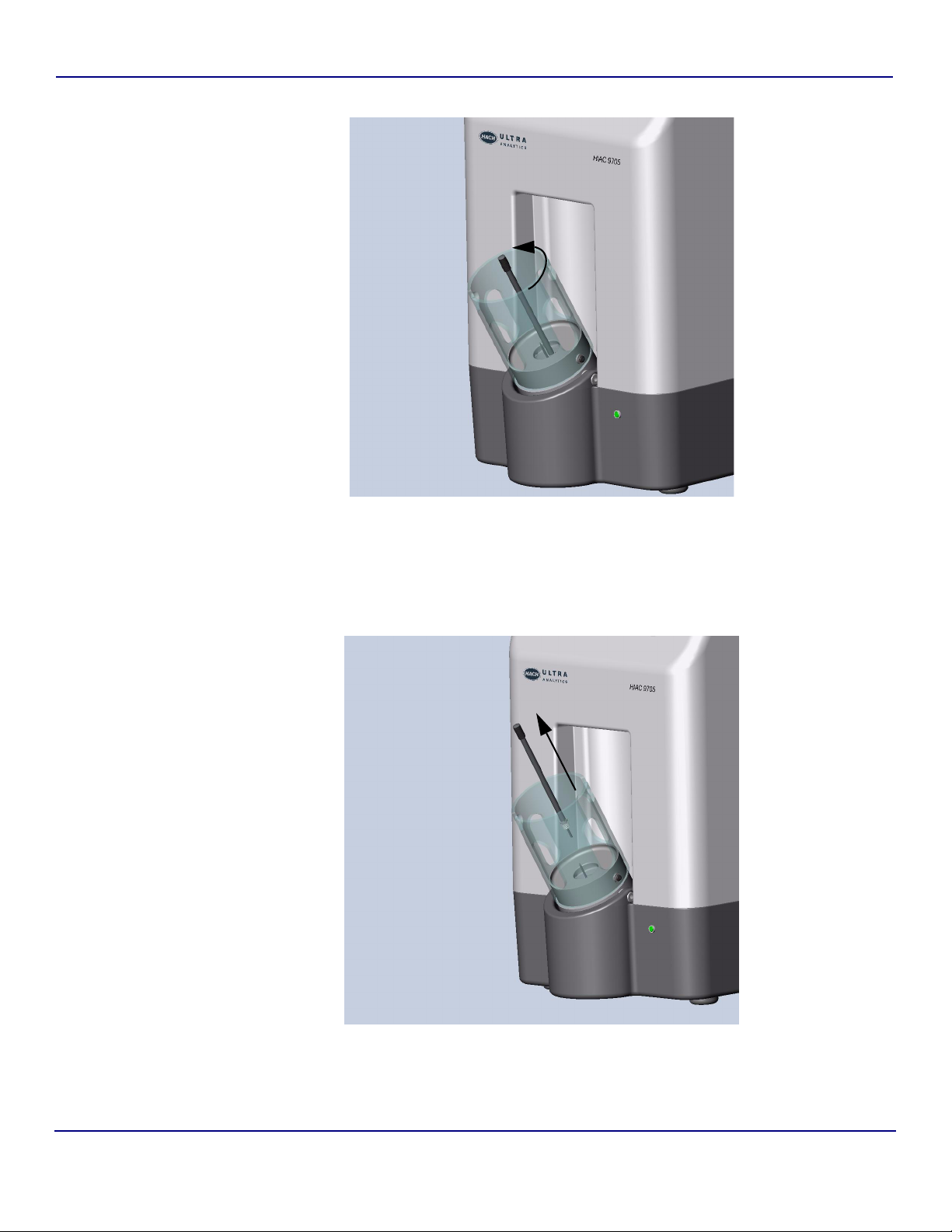
3.9 Changing the Needles
The 9705 comes with two vent needles to allow sampling from a variety of bottle sizes.
• The shorter vent needle is used to sample 5-30 mL bottles.
• The longer vent needle is used to sample 50-125 mL bottles.
The vent needle must be removed to use the Large Volume Adapter (LVA); this process is
described in “Connecting the Large Volume Adapter” on page 35.
e:
The short sampling needle does not need to be removed at any time. Do not attempt to
remove the shortest needle.
To change needles:
1) Tilt the bottle dock forward.
Fig 3-10 : Tilt Bottle Dock
2) Remove the bottle guide.
KSS - March 2006 - Edition 1
Operator Manual HIAC
Page 33

9705 - System Setup 33 of 82
Fig 3-11 : Remove Bottle Guide
3) Carefully slide the removal tool over the longer needle.
Fig 3-12 : Insert Needle Removal Tool
4) Seat the tabs of the removal tool into the slot of the needle screw and turn
KSS - March 2006 - Edition 1
counterclockwise to remove the needle.
HIAC Operator Manual
Page 34
34 of 82 System Setup - 9705
Fig 3-13 : Seat the Tabs
5) Remove the needle from the bottle dock, carefully slide it out of the tool, and place it in
the protective sleeve that it was originally supplied with.
Fig 3-14 : Remove the Needle
Operator Manual HIAC
KSS - March 2006 - Edition 1
Page 35

9705 - System Setup 35 of 82
Not
6) Remove the replacement needle from its protective sleeve and carefully slide it into the
needle removal tool.
7) Insert the needle into the bottle dock by seating the tabs of the removal tool into the slot
of the needle screw and turning clockwise to secure the needle.
8) Remove the tool from the needle.
9) Tilt the bottle dock back. The 9705 is now ready for use with a different sample size.
3.10 Connecting the Large Volume Adapter
The 9705 can also be used with a Large Volume Adapter to sample from vessels greater than
125 mL. Using the Large Volume Adapter (LVA) requires these steps:
1) Remove the vent needle.
2) Connect the Large Volume Adapter to the sample needle.
3) Connect the Large Volume Adapter to the sampling probe.
4) Shorten the adapter tube length, if needed.
5) Calculate and enter the tare volume.
e:
When using the LVA, the stir speed must be set to 0 (off). This procedure is described in
“Changing Sample Parameters” on page 49.
3.10.1 Connecting the Large Volume Adapter to Sample Needle
1) Tilt the bottle dock forward.
Fig 3-15 : Tilt Bottle Dock
KSS - March 2006 - Edition 1
2) Remove the bottle guide.
HIAC Operator Manual
Page 36

36 of 82 System Setup - 9705
Fig 3-16 : Remove Bottle Guide
3) Carefully slide the removal tool over the long needle.
Fig 3-17 : Insert Needle Removal Tool
4) Seat the tabs of the removal tool into the slot of the needle screw and turn
counterclockwise to remove the needle.
Operator Manual HIAC
KSS - March 2006 - Edition 1
Page 37

9705 - System Setup 37 of 82
Fig 3-18 : Seat the Tabs
5) Remove the needle from the bottle dock, carefully slide it out of the tool, and place it in
the protective sleeve that it was originally supplied with.
Fig 3-19 : Remove the Needle
KSS - March 2006 - Edition 1
HIAC Operator Manual
Page 38

38 of 82 System Setup - 9705
6) Prepare the large volume adapter by turning the handle fully counterclockwise. This
opens the internal O-ring.
hold this piece still
Fig 3-20 : Turn the Handle Counterclockwise
7) With the O-ring opened, align the adapter as shown in Figure 3-21, such that the peg
on the bottom aligns with the threaded hole in the bottle dock. Position the hole in the
bottom of the adapter directly over the short needle.
Fig 3-21 : Align the Adapter
Operator Manual HIAC
KSS - March 2006 - Edition 1
Page 39

9705 - System Setup 39 of 82
CAUTION:
Do not damage the tip of the needle. Feed the needle CAREFULLY into the hole adjacent to
the adapter peg.
8) Fully seat the adapter over the short needle such that the bottom sits firmly on the base
of the bottle dock. Turn the adapter handle fully clockwise. This closes the internal
O-ring.
Fig 3-22 : Seat the Adapter
9) Pass the adapter tubing through the center hole of the bottle guide and install the bottle
guide as shown to secure the adapter in place. Use the 20 mL guide for this purpose.
KSS - March 2006 - Edition 1
HIAC Operator Manual
Page 40

40 of 82 System Setup - 9705
Fig 3-23 : Install the Bottle Guide
10) The large volume adapter is now ready to be connected to an external sampling probe,
sample bag, or other vial.
Fig 3-24 : Ready for LVA Connection
Operator Manual HIAC
KSS - March 2006 - Edition 1
Page 41

9705 - System Setup 41 of 82
3.10.2 Connecting the Large Volume Adapter to the Sampling Probe
1) The sampling probe will be attached to a lab stand. Assemble the lab stand
components as shown in step 3-25.
Fig 3-25 : Lab Stand Assembly
KSS - March 2006 - Edition 1
HIAC Operator Manual
Page 42

42 of 82 System Setup - 9705
2) Screw the sampling probe on to the ¼-20 threaded stud on the end of the horizontal
support rod.
Fig 3-26 : Connect the LVA Fitting to the Sampling Probe
3) Connect the large volume adapter fitting to the sampling probe.
Finger-tighten the connection clockwise until it bottoms, and then another 1/8 of a turn.
Operator Manual HIAC
KSS - March 2006 - Edition 1
Page 43

9705 - System Setup 43 of 82
Fig 3-27 : Connect the LVA Fitting to the Probe
Fig 3-28 : Large Volume Adapter Assembly
KSS - March 2006 - Edition 1
HIAC Operator Manual
Page 44

44 of 82 System Setup - 9705
3.10.3 Shortening the Adapter Tube Length
The Large Volume Adapter is supplied with a 24-inch long tube. It has a two piece ferrule preinstalled for connection into the sampling probe. The ferrule can not be re-used. If a shorter
sample tube is desired, then proceed through the following steps.
Fig 3-29 : Ferrule Installation
1) Leave the tube connected to the Large Volume Adapter. Cut the sampling probe end to
the desired length. Make this cut clean and square. Leave the fitting nut on the tube as
shown. Save the tubing that was cut off and observe how the ferrule is installed on it.
Fig 3-30 : Clean Cut of Tube
2) Carefully observe the loose stainless steel ferrule sleeve that has been supplied. Note
that it has a flat end and the opposite end is sharp. It is a tapered sleeve.
Operator Manual HIAC
KSS - March 2006 - Edition 1
Page 45

9705 - System Setup 45 of 82
Fig 3-31 : Flat End Fig 3-32 : Sharp End
3) Orient the two ferrule pieces as shown and slide them onto the tubing in the order
shown.
Sharp end
Flat end
Fig 3-33 : Slide Ferrule Pieces onto Tubing
KSS - March 2006 - Edition 1
HIAC Operator Manual
Page 46

46 of 82 System Setup - 9705
4) Connect the tube to the sampling probe. Tighten it completely by hand.
CAUTION:
The tube is to be inserted and held flush with the bottom of the port while the ferrules are
pushed in and the nut is tightened.
Fig 3-34 : Connect the Tube to the Probe
5) Remove the tube from the sampling probe and inspect the ferrule crimp. It should look
the same as the ferrule cut off in step 1. The tube end should be flush with the ferrule
end and free of nicks and burrs.
Fig 3-35 : Tube End Flush with Ferrule End
Operator Manual HIAC
KSS - March 2006 - Edition 1
Page 47

9705 - System Setup 47 of 82
6) After inspection, re-insert the tube end into the sampling probe and tighten it completely
by hand.
Fig 3-36 : Tighten by Hand
3.10.4 Alternate Use of Lab Stand as Sample Bag Hanger
The optional ram’s horn hook can be fastened to the Lab Stand for hanging flexible bags, such
as IV bags. The user will need to supply a suitable fitting to connect the flexible bag to the 1/8”
outer diameter tubing of the Large Volume Sample Adapter.
KSS - March 2006 - Edition 1
HIAC Operator Manual
Page 48

48 of 82 System Setup - 9705
Fig 3-37 : Ram’s Hook Attachment
3.10.5 Calculating Tare Volume
The tare volume when using the adapter can be calculated by adding the fixed component
volume of 0.83 mL to the volume of the adjustable length tube. To calculate the volume of the
adapter tube, multiply the length of the tube by 0.054.
Operator Manual HIAC
KSS - March 2006 - Edition 1
Page 49

9705 - System Setup 49 of 82
Total Tare Volume = Fixed Component Volume + Tube Volume
Fixed Component Volume
9705 internal tare volume 0.54 mL
Adapter fitting volume 0.11 mL
Sampling probe assembly volume 0.18 mL
0.83 mL Fixed Component Volume
Example tube volume for a 24 inch tube:
Adapter tube 24 inch @ 0.054ml/inch 1.30 mL
1.30 mL Adjustable length tubing volume
Fixed Component Volume 0.83 mL
Tube Volume 1.30 mL
Tot al Tar e Vo l um e 2. 13 m L
7) Once the tare volume has been calculated, modify the tare volume factor in the 9705 by
following the procedure described in “Changing Sample Parameters” on page 49.
3.11 Changing the Syringe Size
1) Load a new syringe into the 9705 by using the procedure outlined in “Syringe
Installation” on page 15.
2) Turn the unit on.
3) From the sliding menu on the Main screen, select the Setup icon > Syringe icon to
invoke the Syringe Settings screen, shown in Figure 3-7 on page 29.
4) To change the syringe size, touch the field to invoke the dropdown menu, then touch
the entry desired to make a selection. Valid entries include:
•1 mL
•10 mL
•25 mL
5) Press the Return icon to save changes and return to the main screen.
3.12 Changing Sample Parameters
1) To change the sample parameters, touch the upper right section of the screen where
the sampling information is listed or from the icon bar on the Main screen, select the
Setup icon > Sample icon, shown in Figure 3-2 on page 23.
2) The Sample Settings screen displays as shown in Figure 3-38.
KSS - March 2006 - Edition 1
HIAC Operator Manual
Page 50

50 of 82 System Setup - 9705
Not
Fig 3-38 : Sample Settings Screen
3) To change a setting, touch the field to change the setting.
• Numeric entry fields invoke a keypad entry screen similar to the one shown in
Figure 3-39.
• Dropdown menu selections are made by touching the field to invoke the menu,
then touching the desired setting to highlight it.
4) Press Save and OK to save the settings and exit the Sample Settings screen.
e:
Press Load to reload the default settings.
Settings for the Sample Settings screen are described in Tab le 3 -4 .
Table 3-4 : Sample Settings Fields
Field Name Description Valid Entries
Number of runs The number of samples taken
from one bottle at one time
Sample Volume The volume of sample taken
from the bottle for each run
Tare A tare volume is a volume of fluid
that is drawn before the counter
begins counting particles. A tare
volume ensures that the sample
fluid is moving at the desired flow
rate and that no liquid meniscus
passes through the sensor
during counting operations.
Refer to “Calculating Tare
Volume” on page 48 when using
the Large Volume Adapter.
1 through 32
0.1 through 10000.0 mL
0.0 through 25.0
KSS - March 2006 - Edition 1
Operator Manual HIAC
Page 51

9705 - System Setup 51 of 82
Table 3-4 :
Field Name Description Valid Entries
Multi-Stroke Tare The multi-stroke tare can be
Dilution Factor Ratio of fluid to be added to the
Stir Speed Speed the stirring mechanism
Sample Settings Fields
used when sampling volumes
larger than the syringe size.
These sample volumes require
the liquid to be brought to speed
before the sample is taken.
sample for dilution.
will agitate the sample bottle.
0.0 through 25.0
1.00 and 99.99
0 through 10
• 0 is off (use with Large Volume Adapter)
• 1 is slowest
• 10 is fastest
Fig 3-39 : Numeric Keypad Entry Screen, Number of Runs
3.13 Automatically Printing Results
The 9705 can automatically print results every time a sample run is completed.
1) From the main screen, select the Settings button > Print to invoke the Print tab,
shown in Figure 3-40.
KSS - March 2006 - Edition 1
HIAC Operator Manual
Page 52

52 of 82 System Setup - 9705
Fig 3-40 : Print Tab
2) Select Automatically Print Runs by touching the checkbox to mark it.
3) Set the average or standard deviation to print by clicking the boxes.
4) Press Return to return to the main screen.
3.14 Password Protection
Password protection enables the functions listed in Table 3-5 to only be accessible once a
password has been entered. When security is enabled, users must enter a password to access
most functions.
Table 3-5 : Functions Affected by Password Security
Affected by Password Security Not Affected by Password Security
• Settings
• Diagnostics
•Flush
•Run
3.14.1 Enabling Password Protection
1) From the Main screen, select the System icon > Security icon to invoke the Security
Settings screen shown in Figure 3-41.
Ability to toggle graph/chart display
Operator Manual HIAC
KSS - March 2006 - Edition 1
Page 53

9705 - System Setup 53 of 82
Not
Not
Fig 3-41 : Security Settings Screen
2) Touch the Enabled Security checkbox to enforce password protection.
CAUTION:
For system security, immediately change the password from the default.
e:
Once a password has been set, it cannot be deleted. If a password is lost or forgotten, call
Hach Ultra at 800.866.7889 or +1-541.472.6500 for assistance.
3) Press the Return icon to save changes and return to the main screen.
3.14.2 Changing the Password
1) From the Main screen, select the System icon > Security icon to invoke the Security
Settings screen shown in Figure 3-41.
2) Press the Change Password icon to invoke the Change Password screen.
3) Touch the Enter New Password field. A keyboard entry screen appears.
4) Enter the new password from the keyboard entry screen.
• Passwords are case-sensitive and must be at least 1 character and no longer
than 12 characters.
• Asterisks appear in the field to preserve the password’s security.
5) Press Enter.
6) Touch the Confirm new password field to invoke a keyboard screen. Re-enter the
new password and press Enter to close the keyboard entry screen.
7) Press the Return icon to save changes and return to the main screen.
e:
Once a password has been set, it cannot be deleted. If a password is lost or forgotten, call
KSS - March 2006 - Edition 1
Hach Ultra at 800.866.7889 or +1-541.472.6500 for assistance.
HIAC Operator Manual
Page 54

54 of 82 System Setup - 9705
3.14.3 Disabling Passwords
1) From the Main screen, select the System icon > Security icon to invoke the Security
Settings screen shown in Figure 3-41.
2) From the Security Settings screen, touch the Enabled Security checkbox to remove
the check and turn off password protection.
3) Press the Return icon to save changes and return to the Setup screen.
Operator Manual HIAC
KSS - March 2006 - Edition 1
Page 55

9705 - Operating the 9705 55 of 82
4 Operating the 9705
The Model 9705 Liquid Particle Counting System operates as both particle counter and
sampler in one self-contained unit.
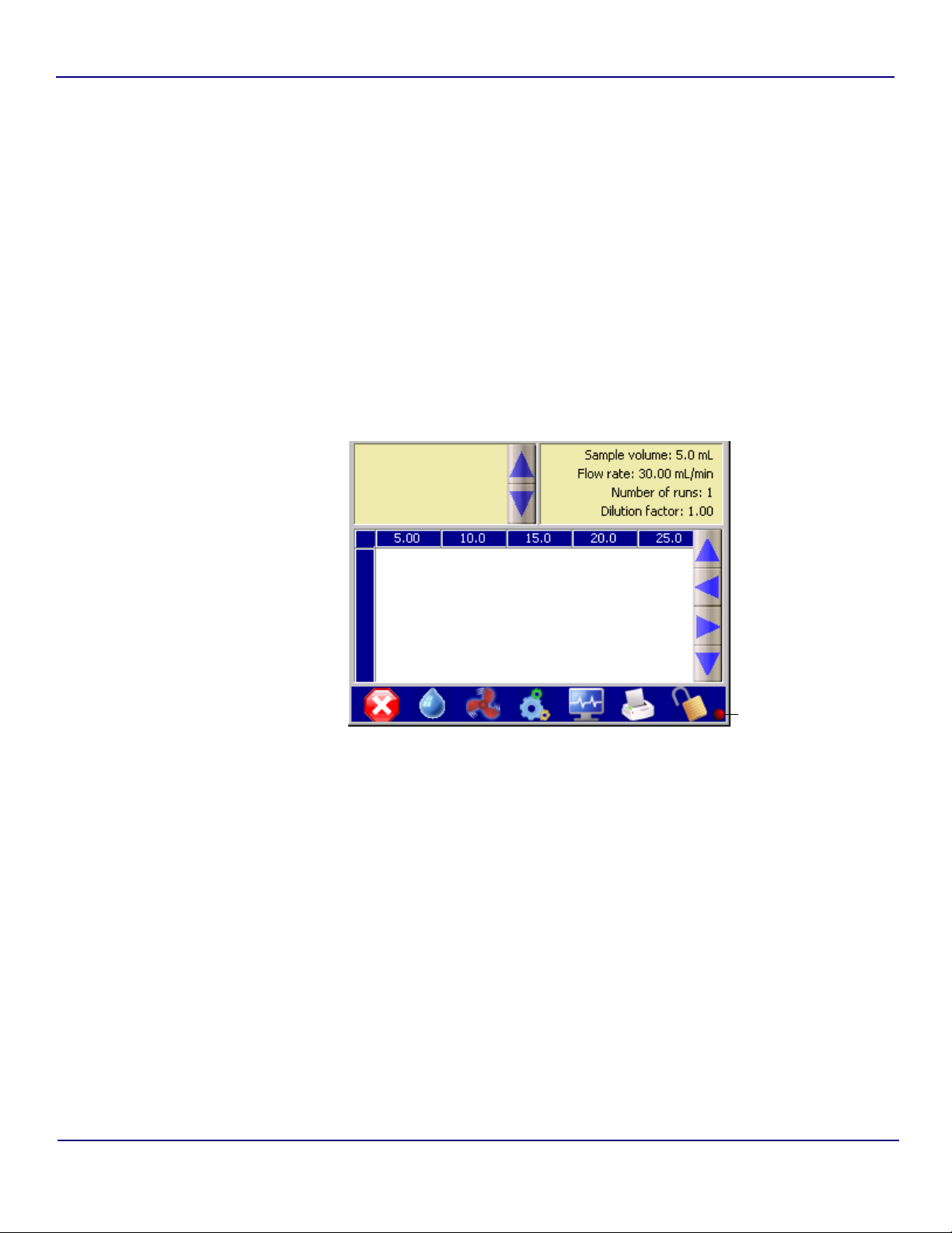
4.1 Touch Screen Familiarization
The touch screen of the 9705 is divided into three sections as shown in Figure 4-1.
• The upper left corner of the screen contains any notes given on a sample. The arrow
keys to the right of the notes field allow scrolling through the notes.
• The upper right corner of the screen shows the current settings for:
• Sample volume
•Flow rate
• Number of runs
• Dilution factor
• The lower half of the screen shows the particle sizes being monitored and either the
current count or the last count taken. The arrows to the right allow scrolling to see all
sizes and counts, if necessary.
• The status of the 9705 is shown at the bottom of the screen, running a sample or sample
stopped.
Fig 4-1 : Main Screen
The icon bar allows access to these functions:
• Run/stop sampling • Flush system
• Swirling • Configure settings
• Check system diagnostics • Print sample results
KSS - March 2006 - Edition 1
• Lock or unlock system security
HIAC Operator Manual
Page 56

56 of 82 Operating the 9705 - 9705
4.2 Preparing Samples
WARNING
Only trained personnel should create septa-sealed sample bottles. Be sure to wear protective
clothing while creating septa-sealed sample bottles, including eye protection.
To prepare samples:
1) Follow good sampling practices to obtain a representative sample as determined by the
applicable standard operating procedure.
2) Make sure bottles are clean by rinsing in deionized water ten times or following the
facility’s Standard Operating Procedures (SOPs) before proceeding.
3) Transfer the sample to the appropriate size sample bottle by pouring, using a pipette, or
following the method specified in the facility’s SOPs.
4) Making sure the top of the bottle is dry, place a septa seal in the opening of the bottle.
5) Place the aluminum seal on top of the septa and use the hand crimper to seal the
bottles.
WARNING
Be careful when crimping the seals to avoid pinching fingers.
4.3 Loading Samples into the Accu-Swirl
WARNING
Needles are sharp. Avoid contact with needles while loading and unloading sample bottles into
the 9705.
To load a sample:
1) Prepare sample as described in “Preparing Samples” on page 56.
CAUTION:
Make sure there is sufficient sample volume in the bottle. Running the 9705 with an insufficient
sample volume loaded may result in erroneous counts.
2) If present, remove the perforated center of the metal seal from the top of the bottle and
discard.
3) Tilt the bottle dock outward, away from the body of the 9705 unit.
4) Position the bottle in the bottle dock with the top (down) facing the needles.
WARNING
Needles are sharp. Be careful not to contact the needles.
5) Press the bottle down gently but firmly. Make sure both needles penetrate the rubber
stopper of the bottle and that the bottle is seated securely.
6) Tilt the bottle dock towards the body of the 9705 unit until it snaps into place.
Operator Manual HIAC
KSS - March 2006 - Edition 1
Page 57
9705 - Operating the 9705 57 of 82
r
4.4 Loading Samples with the Large Volume Adapter
Attach the sample vessel to the 9705 as described in “Connecting the Large Volume Adapter”
on page 35. Make sure the stir speed is set to 0 (off).
4.5 Running a Sample
1) Once the bottle is loaded or the large volume adapter is attached, double-check that
the settings in the upper right hand corner of the display are correct. If necessary,
change settings as described in “Changing Sample Parameters” on page 49.
2) From the Main Screen, press the Swirl icon to begin particle dispersion.
3) Press the Run icon to start the sample run. A red light appears to the right of the Lock
icon in the icon bar, as shown in Figure 4-2. This light appears when a sample is being
drawn, during both tare volume and sample volume.
Test Running Indicato
Fig 4-2 : Main Screen with Red Status Light
4) While the sample run is in progress, parameters cannot be changed. Click on the lower
portion of the main screen to toggle between viewing the data in a chart form and in a
graph form. In the chart form, use the blue arrows at the right of the screen to scroll
through the data. Runs appear on Y-axis; particle sizes appear on the X-axis.
5) If laser current or calibration is detected to be out of range, a yellow caution triangle
appears on the screen. Click on the triangle to invoke the Diagnostic screen. Refer to
“Diagnostics and Troubleshooting” on page 65 for more information.
6) When the run is finished and all samples have been taken from the bottle, the red light
will disappear. Tilt the bottle dock away from the unit to begin unloading the sample.
7) Place fingers through the holes on the side of the bottle dock. Gently but firmly pull up
on the bottle, being careful not to come in contact with the needles.
8) Dispose of any sample bottles according to standard operating procedures (SOPs). Do
not re-use samples since they are no longer sterile.
KSS - March 2006 - Edition 1
HIAC Operator Manual
Page 58

58 of 82 Operating the 9705 - 9705
9) Load a bottle of deionized water and flush the system by pressing the Flush icon to
ensure no sample remains in the inner tubing before running the next sample.
4.5.1 Adding Notes
From the Main Screen, the Notes tab is also available. To add notes about the sample, such
as information about the location, type, or any identifying information about the sample:
1) Touch the upper-left hand corner of the main screen to invoke the Notes screen, shown
in Figure 4-3.
2) To add notes, touch the Add Notes icon to invoke a keyboard entry screen. Notes are
limited to 24 characters per line.
3) Press Enter to return to the Notes screen.
4) Press the Return icon to return to the main screen and start the run. The note will
appear the next time a run is initiated.
4.5.2 Editing Notes
1) To edit a note, access the Notes screen by tapping the upper left corner of the main
screen.
2) Highlight the note and tap Edit. A keyboard entry screen appears. Notes are limited to
24 characters.
3) Press Enter to finish the entry and return to the Notes tab.
4.6 Printing Results
Results may be printed automatically or manually.
4.6.1 Automatically Printing Results
Fig 4-3 : Notes Tab
The 9705 can automatically print results every time a sample run is completed.
Operator Manual HIAC
KSS - March 2006 - Edition 1
Page 59

9705 - Operating the 9705 59 of 82
1) From the main screen, select the Settings icon > Printer icon to invoke the Printer
Settings screen, shown in Figure 4-4.
Fig 4-4 : Print Tab
2) Select Automatically Print Runs by touching the checkbox to mark it.
3) Set the average or standard deviation to print by clicking the boxes.
4) Press Return to return to the Setup screen.
4.6.2 Manually Printing Results
1) From the main screen, select the Print icon.
2) The currently displayed data record prints.
4.7 Operating with PharmSpec
The Model 9705 Liquid Particle Counting System can be used with PharmSpec 2.1 software.
Refer to the PharmSpec Software User Guide (part number 720-100-0063) for additional
information on operating with PharmSpec software.
KSS - March 2006 - Edition 1
HIAC Operator Manual
Page 60

60 of 82 Operating the 9705 - 9705
Operator Manual HIAC
KSS - March 2006 - Edition 1
Page 61

9705 - Maintenance Procedures 61 of 82
Not
5 Maintenance Procedures
5.1 Overview
This section describes maintenance procedures. The recommended intervals for each
procedure are shown in Table 5-1.
Table 5-1 : Preventative Maintenance Timetable
Procedure Daily As Needed
“Cleaning the 9705” on page 61 X
“Flushing the 9705” on page 62 X
“Syringe Maintenance” on page 62 X
“Sensor Port Cleaning” on page 62 X
5.2 Cleaning the 9705
With use, the exterior of the instrument may become dirty or soiled. If liquid spills on the
exterior, or if the instrument becomes dirty, follow these steps to clean the instrument.
WARNING
If a hazardous chemical comes in contact with the touchscreen, clean the touchscreen
immediately to prevent human contact with the chemical.
To clean the touchscreen, first wipe it with a soft cloth. If debris remains, wipe with a soft cloth
moistened with a mild cleaning solution or alcohol.
CAUTION:
Do not spray the touchscreen with solution as the solution may penetrate the electronics and
damage the 9705.
e:
Verify all panels are in place and the interior components are not exposed before starting this
procedure.
1) Wipe the exterior surfaces with a moist cloth.
2) If the instrument is still not clean, wipe any exterior surfaces except for the touchscreen
with soap and warm water. Rinse with a damp cloth.
3) If the instrument is still not clean, moisten a lint-free tissue with isopropyl alcohol. Wipe
the exterior surfaces with the moistened tissue.
KSS - March 2006 - Edition 1
HIAC Operator Manual
Page 62

62 of 82 Maintenance Procedures - 9705
5.3 Flushing the 9705
1) Insert a bottle of deionized (DI) water into the Accu-Swirl or connect the Large Volume
Adapter (LVA) to a container of DI water.
2) From the Main Screen, press Flush. Flush as many as times as required by applicable
3
SOPs. Flushing with at least 10 cm
of clean fluid is recommended.
3) Remove water when finished.
5.4 Syringe Maintenance
The Cavro™ syringes provided for the syringe drive perform optimally when these guidelines
are followed:
• Do not run syringes for more than a few cycles without liquid in them.
• Thoroughly flush the syringe with distilled or deionized water after each use.
• If the plunger is removed from the syringe, wipe the plunger with alcohol before
replacement.
• Clean the syringes periodically with a mild detergent. Allow the detergent to sit in the
syringe for 30 minutes or more, then flush the syringe with distilled or deionized water for
at least 10 cycles.
• If the plunger does not move easily in the barrel, remove the plunger and wet the
plunger seal with deionized water.
5.5 Sensor Port Cleaning
The sensor port should be cleaned whenever large particles clog the cell.
1) Remove the clean-out port cap.
2) Retrieve a clean cell cleaning brush from the shipping container.
3) Slide the brush into the cleaning port, shown in Figure 5-1 until resistance is
encountered.
CAUTION:
Excessive pressure will result in brush and possible cell damage. If the brush will not go into
the cell, pull the brush out and inspect the cleaning tip for damage.
Operator Manual HIAC
KSS - March 2006 - Edition 1
Page 63

9705 - Maintenance Procedures 63 of 82
Fig 5-1 : Insert Brush Into Cleaning Port
4) Gently push the brush into the sensor with a twisting motion.
5) Once the cell has been cleaned with the brush, remove the brush and reinstall the
clean-out port cap. Tighten cap snugly. Do not over-tighten.
6) Flush the sensor with at least 30 cm
3
of clean fluid.
KSS - March 2006 - Edition 1
HIAC Operator Manual
Page 64

64 of 82 Maintenance Procedures - 9705
Operator Manual HIAC
KSS - March 2006 - Edition 1
Page 65

9705 - Diagnostics and Troubleshooting 65 of 82
6 Diagnostics and Troubleshooting
6.1 Error Messages
When error messages occur, a pop-up window appears with the error message highlighted.
Any sound effects related to errors will be heard.
•Press Silence Alarm to stop the sound but keep the error message on the screen.
•Press OK to close the error message pop-up window and view the Diagnostics tab.
Error messages are described in Table 6-1.
Table 6-1 : Error Messages
Error Message Cause Solutions
Syringe door open Occurs when the syringe door is ajar Close syringe door
Communication error Occurs when communications are lost • Double-check all communications connec-
tions.
• Reboot the 9705.
Flow system error Occurs when there is a problem with the flow
of sample through the 9705
• Double-check all communications connections.
• Reboot the 9705.
6.2 Troubleshooting Steps
Ta bl e 6 -2 shows a list of symptoms, possible causes and solutions for various 9705 problems.
Table 6-2 : 9705 Symptoms and Solutions
Symptom Possible Cause Solution
Unit will not power up. Unit may be disconnected from AC
power.
Check fuses in AC power cord. Replace faulty fuses.
Screen is dark. Backlight timeout is in effect. Tap touchscreen.
Check AC power connection.
If tone sounds and screen still does not
light, contact technical support.
6.3 Diagnostics Screen
KSS - March 2006 - Edition 1
Fig 6-1 : Diagnostics Icon
HIAC Operator Manual
Page 66

66 of 82 Diagnostics and Troubleshooting - 9705
When a warning condition exists, such as a value out of range, a yellow Caution! triangle
appears on the screen. Press the yellow triangle or the Diagnostics icon, shown in Figure 6-
1, to invoke the Diagnostics screen, shown in Figure 6-2.
While the 9705 has a limited number of user-serviceable parts, the Diagnostics tab lists
information that may be useful either to the end user or Technical Support.
The Diagnostics screen is divided into four tabs:
•Status
• Factory
• Calibration
• Sensor Log
All Diagnostics tabs allow two functions:
• Printing the information displayed
• Closing the Diagnostics tab via the Return icon
All information is read-only and cannot be edited.
6.3.1 Status Tab
The Status tab, shown in Figure 6-3, lists the information in Table 6-3.
Fig 6-2 : Diagnostics Screen
Operator Manual HIAC
KSS - March 2006 - Edition 1
Page 67

9705 - Diagnostics and Troubleshooting 67 of 82
Fig 6-3 : Status Tab
Table 6-3 :
Field Description
Laser Current Displays the laser current value
Laser Current Status • Normal
Laser Cal Displays the laser calibration voltage
Laser Cal Status • Normal
Printer
USB link Displays current status of the USB link:
Status Tab Fields
• Low (exceeds minimum)
• High (exceeds maximum)
• Low (exceeds minimum)
• High (exceeds maximum)
• Connected
• Offline
KSS - March 2006 - Edition 1
HIAC Operator Manual
Page 68

68 of 82 Diagnostics and Troubleshooting - 9705
6.3.2 Calibration Tab
The Calibration tab lists calibration data thresholds for each particle size channel in the 9705,
as shown in Figure 6-4. This tab is for factory use only.
6.3.3 Factory Tab
The Factory tab lists factory-set information, such as the model number, serial number, and
unit calibration data, as shown in Figure 6-5. This tab is for factory use only.
Fig 6-4 : Calibration Tab
Fig 6-5 : Factory Tab
Operator Manual HIAC
KSS - March 2006 - Edition 1
Page 69

9705 - Diagnostics and Troubleshooting 69 of 82
Table 6-4 : Factory Tab Fields
Field Description Field Values
Model Number Model number of the 9705 Read-only
Serial Number Serial number of the 9705 Read-only
View Volume View volume of the sensor 1 through 100
Calibration Date Date the 9705 was calibrated Read-only
Calibration Due Date Date the 9705’s calibration
Read-only
expires
Sensor Model Number Model number of the sensor Maximum 10 characters
Sensor Serial Number Serial number of the sensor Maximum 10 characters
Concentration Limit Concentration limit of the
0 through 100,000
installed sensor
KSS - March 2006 - Edition 1
HIAC Operator Manual
Page 70

70 of 82 Diagnostics and Troubleshooting - 9705
6.3.4 Sensor Log Tab
The Sensor Log tab lists laser current and calibration information for the 9705, as shown in
Figure 6-6.
Fig 6-6 : Sensor Log Tab
Operator Manual HIAC
KSS - March 2006 - Edition 1
Page 71

9705 - Service Procedures 71 of 82
Appendix A: Service Procedures
A.1 Return Procedures
To return the Model 9705 Liquid Particle Counting System for service, first obtain a returned
material authorization number (RA#). The RA# is necessary for any instrument that requires
repair or calibration by an authorized service center. Include the RA# on the shipping label
when the instrument is returned.
While the RA# process is described in this section, for the most up-to-date RA# process
information, including copies of all required forms, call Hach Ultra at 800.866.7889 or
+1 541.472.6500.
To return an instrument for credit, please contact the local sales representative.
WARNING
The following actions must be performed when returning any unit for any reason to prevent
personal injury and/or damage to the unit.
• Before shipping or storing the unit, run a test without attaching a sample vial to purge the
unit of all liquid.
• All analyzers returned for repair or replacement must be thoroughly cleaned and all
process material is removed.
• Sludge contains bacteria that could be hazardous to Hach Ultra personnel. If a
contaminated unit is received, Hach Ultra reserves the right to have the unit removed
and destroyed by a hazardous material disposal team at the shipper’s expense.
A.2 Technical Support Information
Technical Support Engineers are available to provide high quality advice and
recommendations for applications, product operation, measurement specifications, hardware
and software, factory and customer site training.
Please provide name, company, phone, fax, model number, serial number and comment or
question.
Call +1 (541) 472-6500
Toll Free (800) 866-8854 (US/CA)
Fax +1 (541) 474-7414
6:00 AM to 5:00 PM Pacific Time
Monday through Friday
Email: TechSupportGP@hachultra.com
KSS - March 2006 - Edition 1
HIAC Operator Manual
Page 72

72 of 82 Service Procedures - 9705
Operator Manual HIAC
KSS - March 2006 - Edition 1
Page 73

9705 - Specifications and Accessories 73 of 82
Not
Appendix B: Specifications and Accessories
B.1 Performance Specifications
Temperature Range 10 to 40°C
Relative Humidity 20 to 80%, non-condensing
Temperature Range of Sample 5 to 40°C
Viscosity Limit < 15 cp
Voltage 100 to 240 VAC, 50-60 Hz
Power 90 VA maximum
Current 0.5A at 115VAC
Fusing 1.25A, 250VAC, Type T, SB, 5 x 20mm
Dimensions (H x W x D) 40.5 x 30.1 x 34.3 cm (16.0 x 11.9 x 13.5 in)
Weight 10.7 kg (23.5 lbs)
Sample Bottle Clearance 11.8 cm (4.6 in)
Tare Volume 0.54 mL
Volume Accuracy ± 2%
Flow Rate Accuracy ± 3%
Sample Flow Rate 10 - 60 mL/min; default is 20 mL/min
Concentration Limit 10% coincidence loss @ 10,000 cts/mL (10µm PSL)
Sizing Range 1.3 µm to 150 µm
Sample Vial Sizes 5 mL, 10 mL, 20 mL, 30 mL, 50 mL, 60 mL, 100 mL, 125 mL
Software Compatibility PharmSpec 2.1 or higher
e:
Actual flow rate is determined by the particular sensor calibration flow rate.
B.2 Accessories
Table B-1 :
Part Number Description
VP069201 Sensor Cleaning Brush
2087866-03 100 mL Adapter Ring
2087864-02 Standard Needle for 50-125 mL Bottles
Included Accessories
2087809-01 Large Volume Adapter
210-400-517 Stylus
KSS - March 2006 - Edition 1
2087831 Needle Removal Tool
HIAC Operator Manual
Page 74

74 of 82 Specifications and Accessories - 9705
Table B-1 :
Included Accessories
Part Number Description
460-400-571 USB Cable, 2 m
460519 Printer paper
510667 Power cord
460-400-4799 USB Cable, 2 meter, A to B TYPE
Table B-2 :
Optional Accessories
Part Number Description
2087804-01 Accessory Kit: Adapter rings (5, 10, 20, 30, 60, 100, 125 mL), short needle for
5 - 30 mL bottles, standard needle, printer paper
2088030-XX Sample Prep Kit: Capper tool, decapper tool, 20 bottles, 100 caps and seals,
adapter ring. Specify bottle and adapter ring size.
2087809-02 Large Volume Adapter w/ Integrated Stirrer
690-500-0018 Capper Tool
690-500-0019 Decapper Tool
2087865-01 5 mL Adapter Ring
2087865-02 10 mL Adapter Ring
2087865-03 20 mL Adapter Ring
2087865-04 30 mL Adapter Ring
2087866-02 60 mL Adapter Ring
2087866-04 125 mL Adapter Ring
2087864-01 Short Needle for 5-30 mL Bottles
690-300-0005 Syringe, 1 mL
690-300-0003 Syringe, 25 mL
690-500-0021 Septa Seals
690-500-0023 Aluminum Caps
690-500-2XXX Septa Seal Bottles, specify size
To order these materials, contact a local Hach Ultra representative or contact the factory at
800.866.7889 or +1-541.472.6500.
Operator Manual HIAC
KSS - March 2006 - Edition 1
Page 75

9705 - Certifications 75 of 82
Appendix C: Certifications
C.1 Overview
This section contains the WEEE statement and any Certificates of Conformity. For more
information, contact a local Hach Ultra representative or contact the factory at 800.866.7889 or
+1-541.472.6500.
KSS - March 2006 - Edition 1
HIAC Operator Manual
Page 76

Cat. No. 60235-00
Electrical equipment marked with this symbol may not be disposed of in European
public disposal systems after 12 August of 2005. In conformity with European local
and national regulations (EU Directive 2002/96/EC), European electrical equipment
users must now return old or end-of life equipment to the Producer for disposal at
no charge to the user.
Note: For return for recycling, please contact the equipment producer or supplier
for instructions on how to return end-of-life equipment for proper disposal.
Important document. Retain with product records.
GERMAN
Elektrogeräte, die mit diesem Symbol gekennzeichnet sind, dürfen in Europa nach dem
12. August 2005 nicht mehr über die öffentliche Abfallentsorgung entsorgt werden. In
Übereinstimmung mit lokalen und nationalen europäischen Bestimmungen (EU-Richtlinie
2002/96/EC), müssen Benutzer von Elektrogeräten in Europa ab diesem Zeitpunkt alte bzw.
zu verschrottende Geräte zur Entsorgung kostenfrei an den Hersteller zurückgeben.
Hinweis: Bitte wenden Sie sich an den Hersteller bzw. an den Händler, von dem Sie das
Gerät bezogen haben, um Informationen zur Rückgabe des Altgeräts zur ordnungsgemäßen
Entsorgung zu erhalten.
Wichtige Informationen. Bitte zusammen mit den Produktinformationen aufbewahren.
FRENCH
A partir du 12 août 2005, il est interdit de mettre au rebut le matériel électrique marqué de ce
symbole par les voies habituelles de déchetterie publique. Conformément à la réglementation
européenne (directive UE 2002/96/EC), les utilisateurs de matériel électrique en Europe
doivent désormais retourner le matériel usé ou périmé au fabricant pour élimination, sans
frais pour l’utilisateur.
Remarque : Veuillez vous adresser au fabricant ou au fournisseur du matériel pour les
instructions de retour du matériel usé ou périmé aux fins d’élimination conforme.
Ce document est important. Conservez-le dans le dossier du produit.
ITALIAN
Le apparecchiature elettriche con apposto questo simbolo non possono essere smaltite
nelle discariche pubbliche europee successivamente al 12 agosto 2005. In conformità alle
normative europee locali e nazionali (Direttiva UE 2002/96/EC), gli utilizzatori europei di
apparecchiature elettriche devono restituire al produttore le apparecchiature vecchie o a fine
vita per lo smaltimento senza alcun costo a carico dell’utilizzatore.
Nota: Per conoscere le modalità di restituzione delle apparecchiature a fine vita da riciclare,
contattare il produttore o il fornitore dell’apparecchiatura per un corretto smaltimento.
Documento importante. Conservare con la documentazione del prodotto.
DANI SH
Elektriske apparater, der er mærket med dette symbol, må ikke bortskaffes i europæiske
offentlige affaldssystemer efter den 12. august 2005. I henhold til europæiske lokale og
nationale regler (EU-direktiv 2002/96/EF) skal europæiske brugere af elektriske apparater
nu returnere gamle eller udtjente apparater til producenten med henblik på bortskaffelse
uden omkostninger for brugeren.
Bemærk: I forbindelse med returnering til genbrug skal du kontakte producenten eller
leverandøren af apparatet for at få instruktioner om, hvordan udtjente apparater bortskaffes
korrekt.
Vigtigt dokument. Opbevares sammen med produktdokumenterne.
Page 77

SWEDISH
Elektronikutrustning som är märkt med denna symbol kanske inte kan lämnas in på europeiska
offentliga sopstationer efter 2005-08-12. Enligt europeiska lokala och nationella föreskrifter
(EU-direktiv 2002/96/EC) måste användare av elektronikutrustning i Europa nu återlämna
gammal eller utrangerad utrustning till tillverkaren för kassering utan kostnad för användaren.
Obs! Om du ska återlämna utrustning för återvinning ska du kontakta tillverkaren av
utrustningen eller återförsäljaren för att få anvisningar om hur du återlämnar kasserad
utrustning för att den ska bortskaffas på rätt sätt.
Viktigt dokument. Spara tillsammans med dina produktbeskrivningar.
SPANISH
A partir del 12 de agosto de 2005, los equipos eléctricos que lleven este símbolo no deberán
ser desechados en los puntos limpios europeos. De conformidad con las normativas europeas
locales y nacionales (Directiva de la UE 2002/96/EC), a partir de esa fecha, los usuarios
europeos de equipos eléctricos deberán devolver los equipos usados u obsoletos al fabricante
de los mismos para su reciclado, sin coste alguno para el usuario.
Nota: Sírvase ponerse en contacto con el fabricante o proveedor de los equipos para solicitar
instrucciones sobre cómo devolver los equipos obsoletos para su correcto reciclado.
Documento importante. Guardar junto con los registros de los equipos.
DUTCH
Elektrische apparatuur die is voorzien van dit symbool mag na 12 augustus 2005 niet meer
worden afgevoerd naar Europese openbare afvalsystemen. Conform Europese lokale en
nationale wetgegeving (EU-richtlijn 2002/96/EC) dienen gebruikers van elektrische apparaten
voortaan hun oude of afgedankte apparatuur kosteloos voor recycling of vernietiging naar de
producent terug te brengen.
Nota: Als u apparatuur voor recycling terugbrengt, moet u contact opnemen met de producent
of leverancier voor instructies voor het terugbrengen van de afgedankte apparatuur voor een
juiste verwerking.
Belangrijk document. Bewaar het bij de productpapieren.
POLISH
Sprzęt elektryczny oznaczony takim symbolem nie może być likwidowany w europejskich
systemach utylizacji po dniu 12 sierpnia 2005. Zgodnie z europejskimi, lokalnymi i państwowymi
przepisami prawa (Dyrektywa Unii Europejskiej 2002/96/EC), użytkownicy sprzętu elektrycznego
w Europie muszą obecnie przekazywać Producentowi stary sprzęt lub sprzęt po okresie
użytkowania do bezpłatnej utylizacji.
Uwaga: Aby przekazać sprzęt do recyklingu, należy zwrócić się do producenta lub dostawcy
sprzętu w celu uzyskania instrukcji dotyczących procedur przekazywania do utylizacji sprzętu
po okresie użytkowania.
Ważny dokument. Zachować z dokumentacją produktu.
PORTUGESE
Qualquer equipamento eléctrico que ostente este símbolo não poderá ser eliminado através
dos sistemas públicos europeus de tratamento de resíduos sólidos a partir de 12 de Agosto
de 2005. De acordo com as normas locais e europeias (Directiva Europeia 2002/96/EC), os
utilizadores europeus de equipamentos eléctricos deverão agora devolver os seus
equipamentos velhos ou em fim de vida ao produtor para o respectivo tratamento sem
quaisquer custos para o utilizador.
Nota: No que toca à devolução para reciclagem, por favor, contacte o produtor ou fornecedor
do equipamento para instruções de devolução de equipamento em fim de vida para a sua
correcta eliminação.
Documento importante. Mantenha junto dos registos do produto.
Page 78

Page 79

9705 - Annex 79 of 82
Annex
Tables and illustrations
Fig 1-1 : Model 9705 Liquid Particle Counting System.................................... 11
Fig 2-1 : 9705 Particle Counting System ......................................................... 13
Fig 2-2 : Rear View of 9705.............................................................................14
Fig 2-3 : 9705 Right Side View ........................................................................15
Fig 2-4 : Door Open Error Message ................................................................ 17
Fig 2-5 : Main Screen ......................................................................................18
Fig 2-6 : Setup Screen..................................................................................... 18
Fig 2-7 : Syringe Settings Screen.................................................................... 19
Fig 2-8 : 9705 Left Side View .......................................................................... 20
Fig 2-9 : Main Screen ......................................................................................21
Fig 3-1 : 9705 Icon Bar .................................................................................... 23
Fig 3-2 : Setup Screen..................................................................................... 23
Table 3-1 : Settings Button Functions ................................................................. 24
Fig 3-3 : System Settings Screen .................................................................... 25
Fig 3-4 : Display Settings Tab ......................................................................... 25
Table 3-2 : Display Settings Fields...................................................................... 26
Fig 3-5 : System Settings Screen .................................................................... 26
Fig 3-6 : Sizes Tab .......................................................................................... 27
Fig 3-7 : Syringe Settings Screen.................................................................... 29
Fig 3-8 : System Settings Screen .................................................................... 29
Fig 3-9 : Sound Settings Screen...................................................................... 31
Table 3-3 : Sound Tab Field Descriptions ........................................................... 31
Fig 3-10 : Tilt Bottle Dock ..................................................................................32
Fig 3-11 : Remove Bottle Guide ........................................................................ 33
Fig 3-12 : Insert Needle Removal Tool.............................................................. 33
Fig 3-13 : Seat the Tabs .................................................................................... 34
Fig 3-14 : Remove the Needle........................................................................... 34
Fig 3-15 : Tilt Bottle Dock ..................................................................................35
Fig 3-16 : Remove Bottle Guide ........................................................................ 36
Fig 3-17 : Insert Needle Removal Tool.............................................................. 36
Fig 3-18 : Seat the Tabs .................................................................................... 37
Fig 3-19 : Remove the Needle........................................................................... 37
Fig 3-20 : Turn the Handle Counterclockwise ................................................... 38
Fig 3-21 : Align the Adapter...............................................................................38
Fig 3-22 : Seat the Adapter ............................................................................... 39
Fig 3-23 : Install the Bottle Guide ...................................................................... 40
Fig 3-24 : Ready for LVA Connection................................................................ 40
Fig 3-25 : Lab Stand Assembly .........................................................................41
Fig 3-26 : Connect the LVA Fitting to the Sampling Probe................................ 42
Fig 3-27 : Connect the LVA Fitting to the Probe................................................ 43
Fig 3-28 : Large Volume Adapter Assembly...................................................... 43
KSS - March 2006 - Edition 1
Fig 3-29 : Ferrule Installation............................................................................. 44
HIAC Operator Manual
Page 80

80 of 82 Annex - 9705
Fig 3-30 : Clean Cut of Tube ............................................................................. 44
Fig 3-31 : Flat End ............................................................................................. 45
Fig 3-32 : Sharp End ......................................................................................... 45
Fig 3-33 : Slide Ferrule Pieces onto Tubing ...................................................... 45
Fig 3-34 : Connect the Tube to the Probe ......................................................... 46
Fig 3-35 : Tube End Flush with Ferrule End...................................................... 46
Fig 3-36 : Tighten by Hand ................................................................................ 47
Fig 3-37 : Ram’s Hook Attachment.................................................................... 48
Fig 3-38 : Sample Settings Screen.................................................................... 50
Table 3-4 : Sample Settings Fields......................................................................50
Fig 3-39 : Numeric Keypad Entry Screen, Number of Runs.............................. 51
Fig 3-40 : Print Tab............................................................................................52
Table 3-5 : Functions Affected by Password Security......................................... 52
Fig 3-41 : Security Settings Screen................................................................... 53
Fig 4-1 : Main Screen ...................................................................................... 55
Fig 4-2 : Main Screen with Red Status Light ................................................... 57
Fig 4-3 : Notes Tab.......................................................................................... 58
Fig 4-4 : Print Tab............................................................................................59
Table 5-1 : Preventative Maintenance Timetable................................................ 61
Fig 5-1 : Insert Brush Into Cleaning Port ......................................................... 63
Table 6-1 : Error Messages................................................................................. 65
Table 6-2 : 9705 Symptoms and Solutions..........................................................65
Fig 6-1 : Diagnostics Icon ................................................................................ 65
Fig 6-2 : Diagnostics Screen ........................................................................... 66
Fig 6-3 : Status Tab .........................................................................................67
Table 6-3 : Status Tab Fields .............................................................................. 67
Fig 6-4 : Calibration Tab .................................................................................. 68
Fig 6-5 : Factory Tab ....................................................................................... 68
Table 6-4 : Factory Tab Fields.............................................................................69
Fig 6-6 : Sensor Log Tab................................................................................. 70
Table B-1 : Included Accessories ........................................................................ 73
Table B-2 : Optional Accessories.........................................................................74
Operator Manual HIAC
KSS - March 2006 - Edition 1
Page 81

9705 - User Notes 81 of 82
User Notes
KSS - March 2006 - Edition 1
HIAC Operator Manual
Page 82

Electrical equipment marked with this symbol may not be disposed of in European
public disposal systems after 12 August of 2005. In conformity with European local
and national regulations (EU Directive 2002/96/EC), European electrical equipment
users must now return old or end-of life equipment to the Producer for disposal at no
charge to the user. Note: For return for recycling, please contact the equipment
producer or supplier for instructions on how to return end-of-life equipment for proper
disposal. Important document. Retain with product records.
GERMAN Elektrogeräte, die mit diesem Symbol gekennzeichnet sind, dürfen in Europa nach
dem 12. August 2005 nicht mehr über die öffentliche Abfallentsorgung entsorgt werden. In
Übereinstimmung mit lokalen und nationalen europäischen Bestimmungen (EU-Richtlinie
2002/96/EC), müssen Benutzer von Elektrogeräten in Europa ab diesem Zeitpunkt alte bzw. zu
verschrottende Geräte zur Entsorgung kostenfrei an den Hersteller zurückgeben. Hinweis:
Bitte wenden Sie sich an den Hersteller bzw. an den Händler, von dem Sie das Gerät bezogen
haben, um Informationen zur Rückgabe des Altgeräts zur ordnungsgemäßen Entsorgung zu
erhalten. Wichtige Informationen. Bitte zusammen mit den Produktinformationen aufbewahren.
FRENCH A partir du 12 août 2005, il est interdit de mettre au rebut le matériel électrique
marqué de ce symbole par les voies habituelles de déchetterie publique. Conformément à la
réglementation européenne (directive UE 2002/96/EC), les utilisateurs de matériel électrique
en Europe doivent désormais retourner le matériel usé ou périmé au fabricant pour élimination,
sans frais pour l’utilisateur. Remarque : Veuillez vous adresser au fabricant ou au fournisseur
du matériel pour les instructions de retour du matériel usé ou périmé aux fins d’élimination
conforme. Ce document est important. Conservez-le dans le dossier du produit.
ITALIAN Le apparecchiature elettriche con apposto questo simbolo non possono essere
smaltite nelle discariche pubbliche europee successivamente al 12 agosto 2005. In conformità
alle normative europee locali e nazionali (Direttiva UE 2002/96/EC), gli utilizzatori europei di
apparecchiature elettriche devono restituire al produttore le apparecchiature vecchie o a fine
vita per lo smaltimento senza alcun costo a carico dell’utilizzatore. Nota: Per conoscere le
modalità di restituzione delle apparecchiature a fine vita da riciclare, contattare il produttore o il
fornitore dell’apparecchiatura per un corretto smaltimento. Documento importante. Conservare
con la documentazione del prodotto.
DANISH Elektriske apparater, der er mærket med dette symbol, må ikke bortskaffes i
europæiske offentlige affaldssystemer efter den 12. august 2005. I henhold til europæiske
lokale og nationale regler (EU-direktiv 2002/96/EF) skal europæiske brugere af elektriske
apparater nu returnere gamle eller udtjente apparater til producenten med henblik på
bortskaffelse uden omkostninger for brugeren. Bemærk: I forbindelse med returnering til
genbrug skal du kontakte producenten eller leverandøren af apparatet for at få instruktioner
om, hvordan udtjente apparater bortskaffes korrekt. Vigtigt dokument. Opbevares sammen
med produktdokumenterne.
Form No 011229
Page 83

SWEDISH Elektronikutrustning som är märkt med denna symbol kanske inte kan lämnas in på
europeiska offentliga sopstationer efter 2005-08-12. Enligt europeiska lokala och nationella
föreskrifter (EU-direktiv 2002/96/EC) måste användare av elektronikutrustning i Europa nu
återlämna gammal eller utrangerad utrustning till tillverkaren för kassering utan kostnad för
användaren. Obs! Om du ska återlämna utrustning för återvinning ska du kontakta tillverkaren
av utrustningen eller återförsäljaren för att få anvisningar om hur du återlämnar kasserad
utrustning för att den ska bortskaffas på rätt sätt. Viktigt dokument. Spara tillsammans med
dina produktbeskrivningar.
SPANISH A partir del 12 de agosto de 2005, los equipos eléctricos que lleven este símbolo no
deberán ser desechados en los puntos limpios europeos. De conformidad con las normativas
europeas locales y nacionales (Directiva de la UE 2002/96/EC), a partir de esa fecha, los
usuarios europeos de equipos eléctricos deberán devolver los equipos usados u obsoletos al
fabricante de los mismos para su reciclado, sin coste alguno para el usuario. Nota: Sírvase
ponerse en contacto con el fabricante o proveedor de los equipos para solicitar instrucciones
sobre cómo devolver los equipos obsoletos para su correcto reciclado. Documento importante.
Guardar junto con los registros de los equipos.
DUTCH Elektrische apparatuur die is voorzien van dit symbool mag na 12 augustus 2005 niet
meer worden afgevoerd naar Europese openbare afvalsystemen. Conform Europese lokale en
nationale wetgegeving (EU-richtlijn 2002/96/EC) dienen gebruikers van elektrische apparaten
voortaan hun oude of afgedankte apparatuur kosteloos voor recycling of vernietiging naar de
producent terug te brengen. Nota: Als u apparatuur voor recycling terugbrengt, moet u contact
opnemen met de producent of leverancier voor instructies voor het terugbrengen van de
afgedankte apparatuur voor een juiste verwerking. Belangrijk document. Bewaar het bij de
productpapieren.
POLISH Sprzęt elektryczny oznaczony takim symbolem nie może byćlikwidowany w
europejskich systemach utylizacji po dniu 12 sierpnia 2005. Zgodnie z europejskimi, lokalnymi i
państwowymi przepisami prawa (Dyrektywa Unii Europejskiej 2002/96/EC), użytkownicy
sprzętu elektrycznego w Europie muszą obecnie przekazywać Producentowi stary sprzęt lub
sprzęt po okresie użytkowania do bezpłatnej utylizacji. Uwaga: Aby przekazać sprzęt do
recyklingu, należy zwrócić siędo producenta lub dostawcy sprzętu w celu uzyskania instrukcji
dotyczących procedur przekazywania do utylizacji sprzętu po okresie użytkowania. Ważny
dokument. Zachować z dokumentacją produktu.
PORTUGESE Qualquer equipamento eléctrico que ostente este símbolo não poderá ser
eliminado através dos sistemas públicos europeus de tratamento de resíduos sólidos a partir
de 12 de Agosto de 2005. De acordo com as normas locais e europeias (Directiva Europeia
2002/96/EC), os utilizadores europeus de equipamentos eléctricos deverão agora devolver os
seus equipamentos velhos ou em fim de vida ao produtor para o respectivo tratamento sem
quaisquer custos para o utilizador. Nota: No que toca à devolução para reciclagem, por favor,
contacte o produtor ou fornecedor do equipamento para instruções de devolução de
equipamento em fim de vida para a sua correcta eliminação. Documento importante.
Mantenha junto dos registos do produto.
Form No 011229
Page 84

Dieses Informationsblatt enthält Angaben, die ausschließlich für den Export dieses Gerätes in die Volksrepublik China
erforderlich sind.
This document contains information which is only required for the export of this instrument into the People’s Republic of China.
Ce document contient les informations nécessaires pour l'exportation d'instruments vers la République Populaire de Chine.
本手册只包含出口到中华人民共和国的・ 器的必要信息。
金属(底盘\面板\部件\・罩)
印刷电路板 (PCBA)
电・ &电・ &接・ (Wire/Conn)
・ /电机/励磁器 (Pump or Fan)
光学元件 (Optical Comps)
玻璃 (Glass Fuses)
显示器件 (Display)
○:表示・ 有毒有害物・ 在・ 部件所有均・ 材料中的含量均在 SJ/T11363-2006 ・ 准・ 定的限量要求以下
X:表示・ 有毒有害物・ 至少在・ 部件的某一均・ 材料中的含量超出 SJ/T11363-2006 ・ 准・ 定的限量要求
部件名称
至出售之日,本表格已显示上述电子信息产品中哪些零部件可能存在有害物・ 。
名称:
・
Pb
Optical Particle Counter with Display
有毒有害物・ 或元素
汞
Hg
・
Cd
六价・
Cr6+
多溴联・
PBB
多溴二・ ・
PBDE
X O X X O O
X O X O X X
X O X O X X
X O X X X X
X O O O O O
X O O O O O
X X O O O O
除非另外特别的・ 注,此・ 志为・ 对所涉及产品的・ 保使用期・ 志. 某些可更・ 的零部件会有一个不同的・ 保使用期(例
如,电池单元模・ )・ 在其产品上.
此・ 保使用期限只适用于产品是在产品手册中所・ 定的条件下工作.
15
Form 011360
EUROPE: HACH LANGE
HACH LANGE GMBH – Willstätterstraße 11 – 40549 Düsseldorf – Germany – Phone +49(0)211-5288-143 – info@hach-lange.de
USA AND REST OF WORLD:
Hach Company – P.O. Box 389 – Loveland – Colorado – 80539-0389 – USA – Phone 800-227-4224 – Fax: 970-669-2932 – techhelp@hach.com
 Loading...