

Page 1

DOC022.53.80057
H-Series Meters
10/2013, Edition 2
User Manual
Page 2

Page 3

Table of Contents
Specifications..............................................................................................................3
General information..................................................................................................5
Safety information........................................................................................................5
Use of hazard information....................................................................................5
Precautionary labels.............................................................................................5
Certification........................................................................................................... 6
Product overview.........................................................................................................6
Product components....................................................................................................8
Installation.....................................................................................................................9
Electrical installation....................................................................................................9
Connect to AC power...........................................................................................9
Install the batteries.............................................................................................10
Probe and connection types...............................................................................11
User interface and navigation............................................................................11
Keypad description....................................................................................................11
Display description..................................................................................................... 13
Startup........................................................................................................................... 14
Set the power to on.................................................................................................... 14
Configure the meter...................................................................................................14
Operation.....................................................................................................................15
Configure the Bluetooth™ wireless connection..........................................................
15
Send data to a PC.....................................................................................................16
Keep measurement data...........................................................................................16
Examples of measurement data.........................................................................16
Set the data log..................................................................................................17
Recall the data.................................................................................................... 17
Erase a single data measurement......................................................................17
Erase all measurement data............................................................................... 17
Keep calibration data.................................................................................................17
Recall a calibration.............................................................................................18
Set a passcode..........................................................................................................18
Change a passcode............................................................................................ 19
Override an error.......................................................................................................19
Advanced operation................................................................................................19
Set the pH operations................................................................................................19
Set the manual temperature compensation........................................................ 20
Calibrate for pH measurement...........................................................................20
Set the ISE operations...............................................................................................21
Calibrate for ISE measurement..........................................................................21
Set the conductivity options.......................................................................................22
Set the TDS options................................................................................................... 22
Calibrate for conductivity and TDS measurement..............................................23
Set the DO operations...............................................................................................23
Set the Barometric pressure compensation units...............................................24
Calibrate for DO measurement........................................................................... 24
1
Page 4

Calibrate with a known concentration method............................................. 24
Calibrate with an air-saturated method.......................................................25
Maintenance...............................................................................................................25
Replace the batteries.................................................................................................25
Clean the instrument.................................................................................................. 25
ISFET pH probe maintenance...................................................................................26
Prepare the probe for storage............................................................................26
Calibrate the ISFET probe..................................................................................27
Clean the ISFET probe.......................................................................................27
Repair the ISFET probes....................................................................................27
BNC electrode maintenance......................................................................................28
Clean the electrode............................................................................................28
Troubleshooting.......................................................................................................28
Error codes................................................................................................................29
Replacement parts and accessories...............................................................30
Table of Contents
2
Page 5

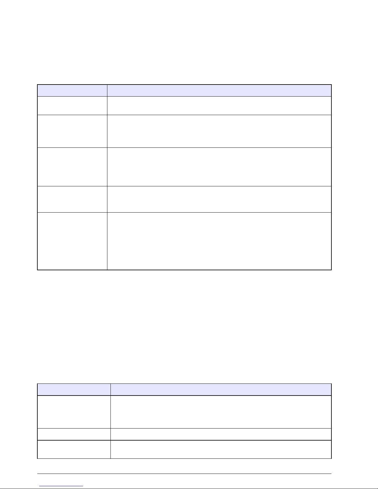
Specifications
Specifications are subject to change without notice.
Specification Details
Dimensions (W x D x H) Handheld meters: 9 x 20 x 5 cm (3.5 x 8 x 2 in.)
Benchtop meters: 20 x 13 x 8 cm (5 x 8 x 3 in.)
Weight Handheld meters: 1300 g (3.0 lb.)
Benchtop meters: 900 g (2.0 lb.)
Battery enclosure Water resistant
Battery requirements 4-ANSI 15 A or IEC-LR6 (AA Alkaline)
Power consumption Backlight on and Bluetooth™ active: 1 W
Backlight on and Bluetooth™ inactive: 50 mW
Power source Internal power source: 4 AA alkaline or rechargeable nickel metal hydride (NiMH)
batteries; battery life: > 200 hours
External power source: 100 to 240 VAC, 50/60 Hz input; 4.5 to 7.0 VDC; 100 mA
(benchtop meters only)
Storage temperature –20 to +40 °C (4 to 140 °F)
Operating temperature 5 to 40 °C (41 to 104 °F)
Operating humidity Relative humidity: 50% maximum at 25 ºC (77 ºF), non-condensing
Input connectors Handheld meters: 8-pin ISFET, BNC with phono jack temperature, 12-pin conductivity
(H170G only)
Benchtop meters: 8-pin ISFET BNC with phono jack temperature, 12-pin conductivity
(H270G only), 2 mm reference, USB and external AC
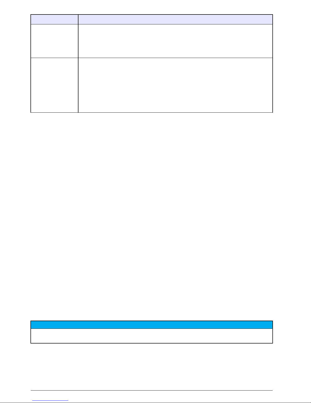
USB adapter Peripheral
Data memory (internal) Up to 999 measurement results at user selectable intervals from 1 to 1999 seconds
Data storage Automatic in store mode; user enables data logging mode; data is user stored, recalled
and deleted
Data export USB connection to PC; transfer the data log or as data is read
Languages English
Temperature correction Off, automatic and manual (parameter dependent)
Measurement Continuous measurement
Protection rating Handheld meters: IP67
Benchtop meters: IP42
Certifications CE
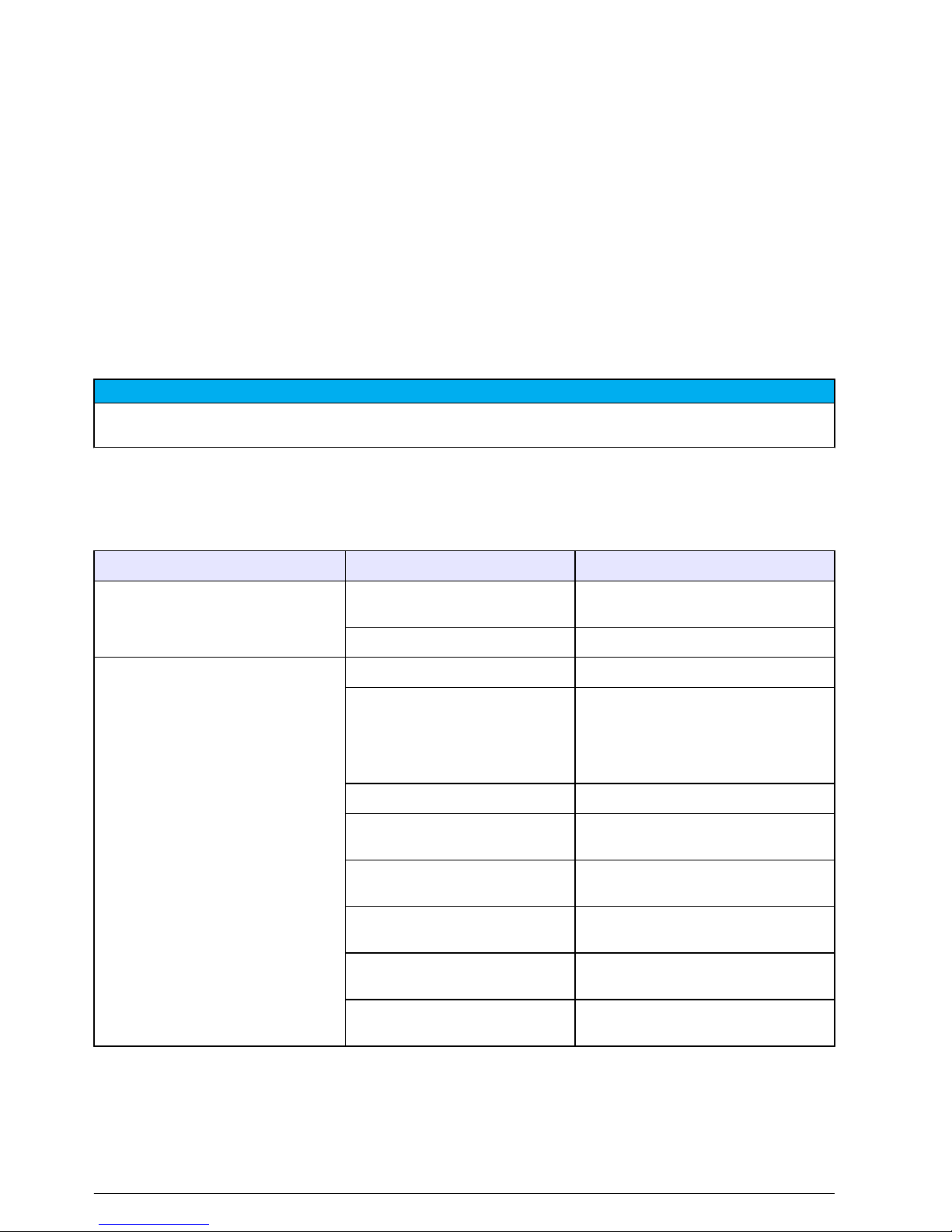
pH
Calibration Up to five points: 1.68, 4.01, 6.86, 7.00, 9.18, 10.01, 12.45
Accuracy ±0.01 pH
Resolution 0.01 pH
Range -2.00 to 19.99
mV
Calibration None
Accuracy ±1 mV
English 3
Page 6

Specification Details
Resolution Autoranging, 0.1 and 1
Range Autoranging, ±199.9 mV to ±1999 mV
Temperature
Calibration None
Accuracy ±0.5 °C
Resolution 0.1 °C (0.1 °F)
Range -5 to 105 °C (23 to 221 °F)
ISE
Calibration Up to five points
Accuracy Probe dependent
Resolution 0.1 ppm–0.1 ppt
Range Autoranging, -0.0 ppm to 1999 ppt
Conductivity
Calibration Up to five points
Accuracy ±1% full scale or ±1 digit
Resolution 0.01 µS, 0.1 µS, 1 µS, 0.01 mS, 0.1 mS
Range Autoranging: 0.00 to 19.99 µS, 20.0 to 199.9 µS, 200 to 1999 µS, 2.00 to 19.99 mS,
20.0 to 199.9 mS
TDS
Calibration Up to five points
Accuracy ±1% full scale or ±1 digit
Resolution 0.01 ppm, 0.1 ppm, 1 ppm, 0.01 ppt, 0.1 ppt, 1 ptt, 0.1 mg/L, 1 mg/L, 0.01 gal/L,
0.1 gal/L
Range Autoranging, ppm: 0.00 to 9.99 ppm,10.0 to 99.9 pm,100 to 999 ppm,1.00 to 9.99 ppt,
10.0 to 99.9 ppt,100 to 200 ppt
mg/L: 0.00 to 199.9 mg/L, 200 to 1999 mg/L, 2.00 to 19.99 gal/L, 20 to 50 gal/L
Salinity
Calibration None (derived from conductivity)
Accuracy ±0.1 ppt (–2 to +35 °C or 28.4 to 95 °F)
Resolution 0.1 ppt, 1%
Range 0 to 42, ppt 0 to 4.2%
Dissolved oxygen
Calibration One or two points, user-selectable to any value
Accuracy ±1.5% full scale
Resolution 0.1%, 0.01 ppm or mg/L
Range 0.0% to 199.9% saturation, 0 to 19.99 ppm or mg/L
Salinity correction: automatic with conductivity probe
Barometric pressure compensation: automatic
4 English
Page 7

Specification Details
Barometric pressure
Calibration Factory calibration
Accuracy ±1.5 hPa (10 to 40 °C or 50 to 104 °F)
Resolution 1 mm Hg or 1 hPa 0.01 in Hg±
Range 225 to 900 mm Hg or 300 to 1200 hPa (8.86 to 35.43 in. Hg)
General information
In no event will the manufacturer be liable for direct, indirect, special, incidental or consequential
damages resulting from any defect or omission in this manual. The manufacturer reserves the right to
make changes in this manual and the products it describes at any time, without notice or obligation.
Revised editions are found on the manufacturer’s website.
Safety information
N O T I C E
The manufacturer is not responsible for any damages due to misapplication or misuse of this product including,
without limitation, direct, incidental and consequential damages, and disclaims such damages to the full extent
permitted under applicable law. The user is solely responsible to identify critical application risks and install
appropriate mechanisms to protect processes during a possible equipment malfunction.
Please read this entire manual before unpacking, setting up or operating this equipment. Pay
attention to all danger and caution statements. Failure to do so could result in serious injury to the
operator or damage to the equipment.
Make sure that the protection provided by this equipment is not impaired. Do not use or install this
equipment in any manner other than that specified in this manual.
Use of hazard information
D A N G E R
Indicates a potentially or imminently hazardous situation which, if not avoided, will result in death or serious injury.
W A R N I N G
Indicates a potentially or imminently hazardous situation which, if not avoided, could result in death or serious
injury.
C A U T I O N
Indicates a potentially hazardous situation that may result in minor or moderate injury.
N O T I C E
Indicates a situation which, if not avoided, may cause damage to the instrument. Information that requires special
emphasis.
Precautionary labels
Read all labels and tags attached to the instrument. Personal injury or damage to the instrument
could occur if not observed. A symbol on the instrument is referenced in the manual with a
precautionary statement.
English 5
Page 8
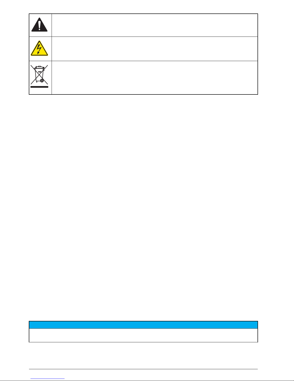
This is the safety alert symbol. Obey all safety messages that follow this symbol to avoid potential
injury. If on the instrument, refer to the instruction manual for operation or safety information.
This symbol indicates that a risk of electrical shock and/or electrocution exists.
Electrical equipment marked with this symbol may not be disposed of in European public disposal
systems after 12 August of 2005. In conformity with European local and national regulations (EU
Directive 2002/96/EC), European electrical equipment users must now return old or end-of-life
equipment to the Producer for disposal at no charge to the user.
Note: For return for recycling, please contact the equipment producer or supplier for instructions on how to return endof-life equipment, producer-supplied electrical accessories, and all auxiliary items for proper disposal.
Certification
Canadian Radio Interference-Causing Equipment Regulation, IECS-003, Class A:
Supporting test records reside with the manufacturer.
This Class A digital apparatus meets all requirements of the Canadian Interference-Causing
Equipment Regulations.
Cet appareil numérique de classe A répond à toutes les exigences de la réglementation canadienne
sur les équipements provoquant des interférences.
FCC Part 15, Class "A" Limits
Supporting test records reside with the manufacturer. The device complies with Part 15 of the FCC
Rules. Operation is subject to the following conditions:
1. The equipment may not cause harmful interference.
2. The equipment must accept any interference received, including interference that may cause
undesired operation.
Changes or modifications to this equipment not expressly approved by the party responsible for
compliance could void the user's authority to operate the equipment. This equipment has been tested
and found to comply with the limits for a Class A digital device, pursuant to Part 15 of the FCC rules.
These limits are designed to provide reasonable protection against harmful interference when the
equipment is operated in a commercial environment. This equipment generates, uses and can
radiate radio frequency energy and, if not installed and used in accordance with the instruction
manual, may cause harmful interference to radio communications. Operation of this equipment in a
residential area is likely to cause harmful interference, in which case the user will be required to
correct the interference at their expense. The following techniques can be used to reduce
interference problems:
1. Disconnect the equipment from its power source to verify that it is or is not the source of the
interference.
2. If the equipment is connected to the same outlet as the device experiencing interference, connect
the equipment to a different outlet.
3. Move the equipment away from the device receiving the interference.
4. Reposition the receiving antenna for the device receiving the interference.
5. Try combinations of the above.
Product overview
N O T I C E
Always disconnect power to the meter when electrodes are changed. Only use the meter as instructed in this
manual or the meter performance can decrease.
The H-series handheld and benchtop meters operate with glass sensor electrodes with BNC
connectors or non-glass probes with ISFET (ion sensitive field effect transistor) silicon chip sensors.
6 English
Page 9

The meters use one pH electrode (a BNC pH electrode or an ISFET pH probe) at a time. When the
meter power is set to on, the meter automatically identifies the type of electrode that is attached.
The H-Series meters are available in eight models:
• Waterproof handheld meters with Bluetooth™ technology. Refer to Figure 1:
• H160G—pH and ORP
• H170G—pH, ORP, conductivity, TDS and salinity
•
Benchtop meters with a USB output. Refer to Figure 2:
• H260G—pH and ORP
• H270G—pH, ORP, conductivity, TDS and salinity
• H280G—pH, ORP, conductivity, TDS, salinity and dissolved oxygen (DO)
• Benchtop meters with Bluetooth™ technology and a USB output. Refer to Figure 2:
• H260GB—pH and ORP
• H270GB—pH, ORP, conductivity, TDS and salinity
• H280GB—pH, ORP, conductivity, TDS, salinity and DO
Note: The difference between the benchtop meters is that the GB benchtop meters have Bluetooth™ technology
and a USB output, and the G benchtop meters only have a USB output. Unless noted, when the benchtop series is
documented in this manual, the benchtop meter includes all of the H-series benchtop meters (both the G and the
GB benchtop meters).
Figure 1 Handheld meter
1 Rubber dust caps 5 ISFET pH probe connector (8-pin)
2 Conductivity probe connection (12-pin, H170G only) 6 LCD display
3 BNC probe connector 7 Power button
4 3.5 mm phono jack for glass pH electrode, ISE,
ORP or DO temperature sensors
8 Battery cover
English 7
Page 10

Figure 2 Benchtop meter
1 Power button 6 ISFET pH probe connector
2 Conductivity probe connector (12-pin, H270G and
H280G only)
7 AC power connector
3 USB connector 8 External reference connector
4 3.5 phono jack for glass pH electrode, ORP, ISE or
DO temperature sensors
9 LCD display
5 BNC connector for glass pH electrode, ISE, ORP or
DO (H280G only) probes
10 Battery cover
Product components
Make sure that all components have been received. Refer to Figure 3. If any items are missing or
damaged, contact the manufacturer or a sales representative immediately.
8 English
Page 11

Figure 3 Handheld and benchtop meter components
1 Waterproof handheld meter 4 Benchtop meter
2 SmartLogger II software 5 USB cable
3 AA Alkaline batteries (4x) 6 AC-DC power supply kit (power supply and three
plugs: US, EU, UK)
Installation
C A U T I O N
Multiple hazards. Only qualified personnel must conduct the tasks described in this section of the
document.
Electrical installation
Connect to AC power
D A N G E R
Electrocution hazard. If this equipment is used outdoors or in potentially wet locations, a Ground Fault
Circuit Interrupt (GFCI/GFI) device must be used for connecting the equipment to its main power
source.
English 9
Page 12
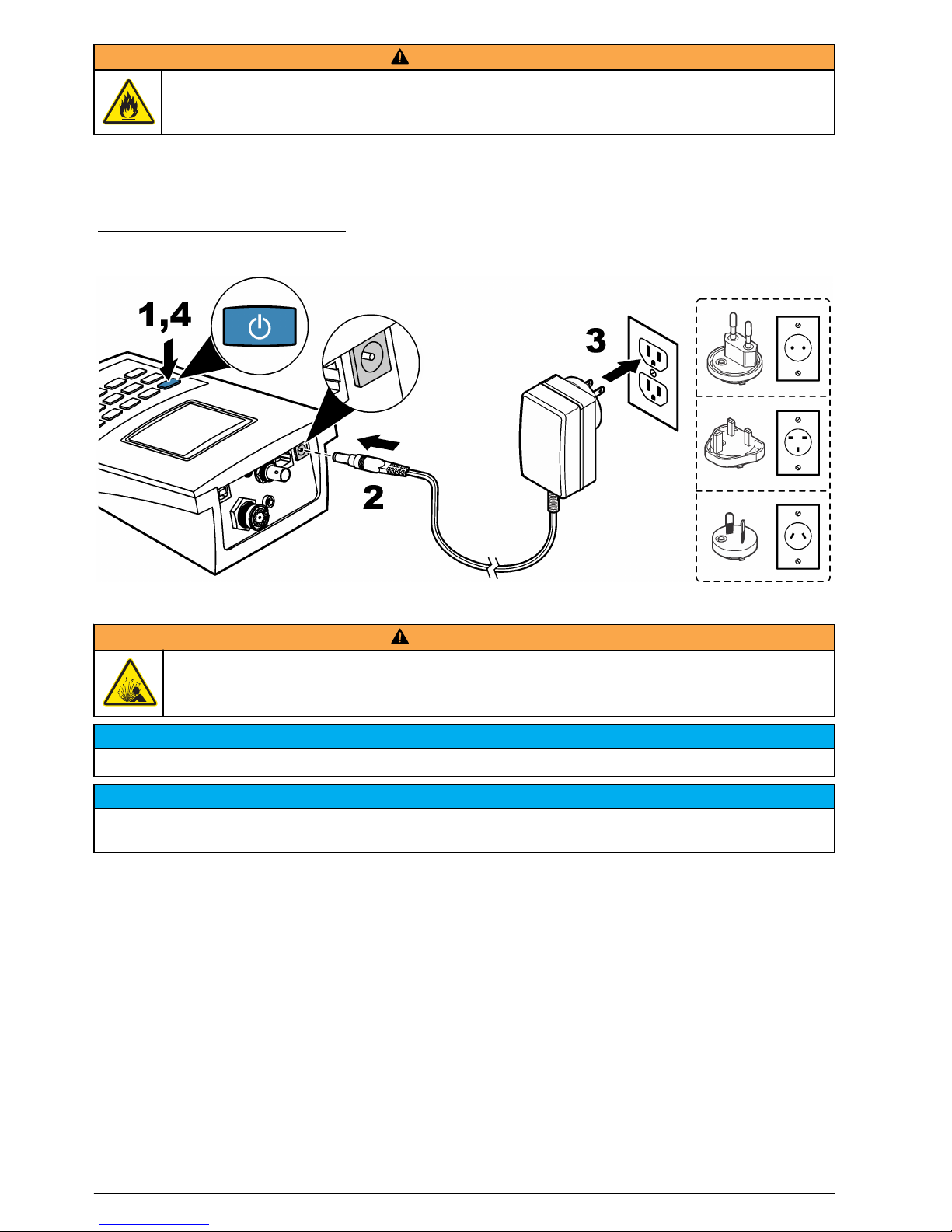
W A R N I N G
Fire hazard. Use only the power supply that is specified for this instrument.
The benchtop meters use AC power with an AC power adapter kit. Refer to Product components
on page
8. The kit includes an AC-DC power supply, USB/DC adapter and AC power cord. Refer to
Figure 4
for AC power connections.
Note:
Always set power to off before any power connections are made.
Figure 4 AC power connection
Install the batteries
W A R N I N G
Explosion hazard. Incorrect battery installation can cause the release of explosive gases. Be sure that
the batteries are of the same approved chemical type and are inserted in the correct orientation. Do not
mix new and used batteries.
N O T I C E
Do not tighten the screws too much or instrument damage can occur.
N O T I C E
Only do this procedure if the power to the meter is set to off or disconnected. Do not complete this operation with
probes attached to the meter. Remove all probes from the meter or instrument damage can occur.
The meter uses AA alkaline or rechargeable NiMH batteries. To conserve the battery life, refer to
Configure the meter on page 14 to configure automatic shutdown of the meter.
Refer to Figure 5 to install the batteries.
Items to collect:
•
Phillips screwdriver (for handheld meters)
• Flathead screwdriver (for benchtop meters)
• AA Alkaline batteries (4x)
10 English
Page 13
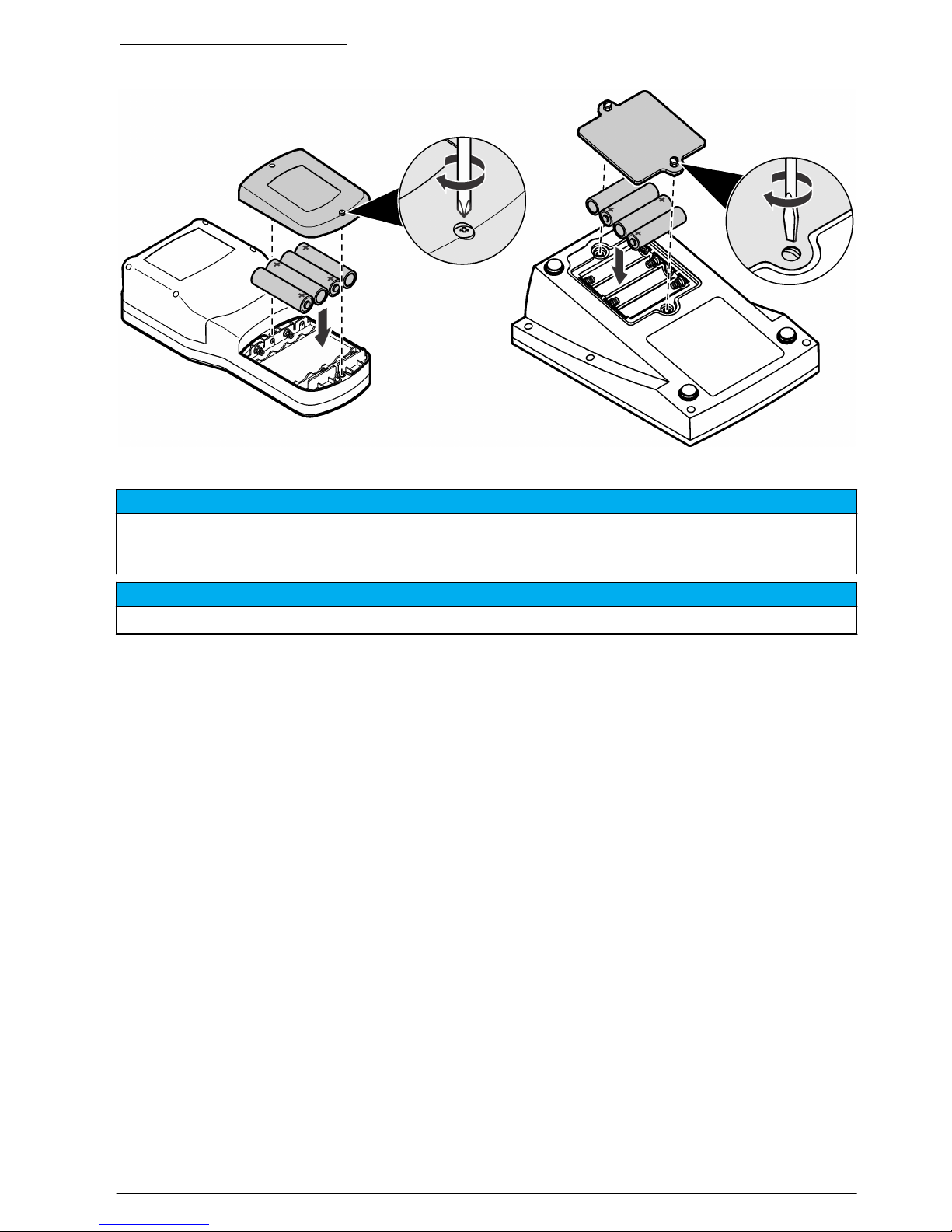
Figure 5 Battery installation
Probe and connection types
N O T I C E
Make sure that all the rubber plugs are fully installed before the handheld meter is put in water or the interior of
the 3.5 mm phono jack will fill with water. The interior of the handheld meter will stay sealed. If water gets into the
3.5 mm phono jack, immediately invert the meter to let water come out of the phono jack. Let the connector dry.
N O T I C E
Always set the power to off before a probe connection is changed or damage to the instrument can occur.
The meters can connect to two pH-sensing technologies: ISFET pH probes and glass electrodes.
When the meter is set to on, it automatically identifies the type of probe attached. The meter only
uses one type of pH probe at a time. Refer to Product overview on page 6.
Note: When a probe is not attached to the meter, the selected mode is inactive.
User interface and navigation
Keypad description
Figure 6 shows the handheld and benchtop meter keypads. Table 1 gives the function of the keys on
the keypad and the meters that use that function.
English 11
Page 14

Figure 6 Keypad description
Table 1 Keypad functions
Key Action H160G
H260G
H260GB
H170G
H270G
H270GB
H280G
H280GB
ON/OFF: Set the meter power to on or to off. x x x
pH mode x x x
mV mode x x x
ISE mode x x x
TDS mode x x
Conductivity mode x x
Salinity mode x x
Calibration mode x x x
DO mode x
Setup mode x x x
Barometric pressure mode x
12 English
Page 15

Table 1 Keypad functions (continued)
Key Action H160G
H260G
H260GB
H170G
H270G
H270GB
H280G
H280GB
Time and date display x x x
Store a reading x x x
Recall a stored reading. x x x
Delete a stored reading. x x x
Scroll through values, setup screens and options. x x x
Set the backlight to on. After 2 minutes without a keystroke, the
backlight is set to off.
x x x
Start/stop the data log x x x
Select an option, setting or value. x x x
Cancel an option, setting or value. x x x
Display description
Figure 7 shows the measurement modes and values, data connection and storage options, battery
status, temperature values, stabilization lock and connection statuses shown on the display.
English 13
Page 16

Figure 7 Display
1 Data log indicator 10 Data storage memory location
2 Temperature and data values 11 Automatic temperature compensation (ATC) value
(pH, conductivity, TDS or salinity)
3 Measured value 12 Calibration mode indicator
4 Stabilization lock 13 Temperature unit
5 Hold indicator 14 Low battery indicator
6 ISFET probe indicator 15 Bluetooth™ connection indicator
7 Measurement mode 16 PC data transfer icon
8 Measurement units 17 Setup mode
9 Storage options
Startup
Set the power to on
Push the power button to set the power to on or off. Make sure that the power supply (AC power or
battery power) is correctly installed.
Configure the meter
Do the operations in order:
1. Set the power to on.
2. Push SETUP to put the meter in setup mode.
3. Use the arrow keys to select an option, then push ENTER:
Option Function Description
CLr ALL
CAL
Clear calibration
points
Erases all the calibration points. Make sure to calibrate the meter.
1
int Data log interval Keeps up to 999 data points in intervals from 1 to 1999 seconds (default =
10) in the data log.
year Year Use the number keys to enter the correct year.
14 English
Page 17

Option Function Description
date Date format Sets the date to mm/dd/yy or dd/mm/yy format.
m/d date Month and day Use the number keys to set the correct month and day.
time Time Sets the correct time in a 24-hour format. Use the number keys to set the
correct time.
oFF Automatic
shutdown
Sets the shutdown parameters from 1 minute to 000 minutes (continuous
power). The meter beeps 1 minute before shutdown. Make sure to power
cycle for the automatic shutdown to occur. Automatic shutdown is disabled
during: data logging, Bluetooth™ transfers and when connected to the USB
port.
Snd Sound options Sets sound alerts to on or off. Three sounds tell the user about different
functions:
• One beep: Stabilization occurred with the stabilization lock on.
• Two beeps: An error occurred. The error code shows on the display.
Refer to Troubleshooting on page 28.
• Three beeps: Measurement stability in calibration mode, regardless of
the stabilization lock setting.
ºC ºF Temperature
display
Sets the temperature unit from ºC to ºF.
READY Stabilization lock Sets the stabilization lock to on or off:
• The "READY" icon shows when an endpoint occurs and the stabilization
lock is set to on.
• After stabilization, the display locks the value and the meter ignores slight
measurement changes in pH, conductivity or TDS.
• Sets the stabilization lock to off during titrations or slight change
detection. The display automatically unlocks after a significant
measurement change is found.
1
This does not erase calibration data for an ISFET probe.
4. Push ENTER to keep the changes and go back to setup mode.
Note: To exit and not keep the changes, push CANCEL.
Operation
Configure the Bluetooth™
wireless connection
Transfer data and control several instrument functions from a remote location to a PC with the
Bluetooth™ wireless connection.
Note: The arrow icon shows on the display when the meter is in communication with the SmartLogger II software
on a PC. The arrow icon flashes when data is transferred. Refer to the SmartLogger II documentation to setup the
wireless connection to a PC.
1. Set the power to on. The meter looks for the Bluetooth™ connection with a PC.
2. On the PC, select the option to find or add a Bluetooth™ device. Next, the PC prompts if the user
wants to pair with a found device.
3. When the PC prompts for a pass key or PIN, enter the PIN (default = 1234). The PC shows if the
pair is successful and the meter shows the Bluetooth™ icon.
4. If the pair is not successful, do steps
1 through 4 again.
Note: If there is more than one meter in range, each meter is identified with the model number and the serial
number (e.g., H170G LP SN1 2755).
English 15
Page 18

Send data to a PC
Transmit data in storage to a PC and see real-time measurement values from a remote location on a
PC. Refer to the SmartLogger II PC software guide for operation instructions for the PC to USB
connection.
1. Set the power to off.
2. Connect the USB cable to the USB port of the PC.
3. Use the USB drivers to make a USB connection to the PC.
4. Set the power to on. Refer to the SmartLogger II documentation for data transfer information.
Keep measurement data
Keep up to 999 measurement readings to review, download or print later.
1. Push STORE during a data measurement. The meter shows the next available sample number,
then the "?" icon flashes.
2. Push STORE again. The data is kept in that memory location and the meter goes back to the
measurement mode.
3. To keep data in a different sample number, use the number keys to select a different sample
number. Push ENTER to keep the measurement in this memory location.
Note: The meter beeps two times if a sample number already contains data or if all memory locations are full. The
meter will prompt: "DELETE SAMPLE?". Push ENTER to overwrite the data in that location with the current data.
Push CANCEL to exit to keep the current data.
Examples of measurement data
pH and ISE measurements
• Sample number
• pH or ISE value
• mV value (pH)
• Sample temperature
•
Temperature compensation (automatic or manual values)
• Date and time
• Meter serial number
• Probe serial number (ISFET)
• Software version
• Calibration date and time
Conductivity, TDS, salinity and DO measurements
• Sample number
• Conductivity, TDS, salinity or DO values
• Sample temperature
• mV value (pH)
• Temperature normalization (20 to 25 ºC or 68 to 77 ºF)
• Temperature compensation coefficient (conductivity/TDS)
• Salinity adjustment (DO)
• Barometric pressure (DO)
• Calibration date and time
• Meter serial number
• Software version
16 English
Page 19

Set the data log
Note: The data log procedure stops during calibration and setup. Calibration alarms are not active during the data
log procedure.
1. When the meter is in read mode, push LOG to record data. The "LOGGING" icon flashes and the
digits in the lower right corner shows the number of collected data points.
2. To stop a data log procedure, push LOG.
3. To continue a data log procedure, push LOG again.
Note: Monitor data log memory to prevent data loss. If the memory is full, the meter deletes every evennumbered data point and continues to record data.
Recall the data
To recall data in storage or logged data:
1. In the measurement mode, push RECALL.
2. Push STORE to recall data in storage or push LOG to recall logged data.
3. To see the last data storage location, push RECALL.
4. To select a different location, use the numeric keypad to enter the location number, then push
ENTER.
Note:
If the user tries to recall data from a location with no data in storage, the display shows "NO." If "NO"
shows, use the arrow keys to scroll to another data storage location.
5. To show the time a sample in storage was recorded, push TIME.
6. To show the date a sample in storage was recorded, push TIME again.
7. Push pH, ISE, COND, TDS, SAL or DO or CANCEL to go back to measurement mode.
Erase a single data measurement
Erase a data measurement or specific data measurements. Refer to Erase all measurement data
on page 17 to erase all data measurements.
1. Push RECALL in the measurement mode.
2. Push STORE CAL or LOG to recall calibration or logged data records. The number of the last
data measurement location shows.
3. Push RECALL to see the data.
4. To select a different memory location, use the numeric keypad to enter the location number, then
push ENTER.
5. When the data to delete shows on the display, push DELETE. The meter will show "DELETE ?".
6. Push ENTER to erase a data measurement.
Note: To exit and not keep the changes, push CANCEL.
7. Push pH, ISE, COND, TDS, SAL or DO to go back to the measurement mode.
Erase all measurement data
Refer to Erase a single data measurement on page 17 to erase specific data measurements. To
erase all data in storage or all logged data measurements:
1. With a sample shown, push DELETE. The meter shows "DELETE SAMPLE?".
2. Push STORE or LOG to recall data. The number of the last data measurement location shows.
3. Push RECALL to show the data.
4. Push 0, then ENTER and the meter shows "ALL."
5. Push ENTER to erase all data in storage or logged data.
Note: To exit and not keep the changes, push CANCEL.
Keep calibration data
The meter keeps the last 10 calibrations. Table 2 shows the date for each calibration.
English 17
Page 20
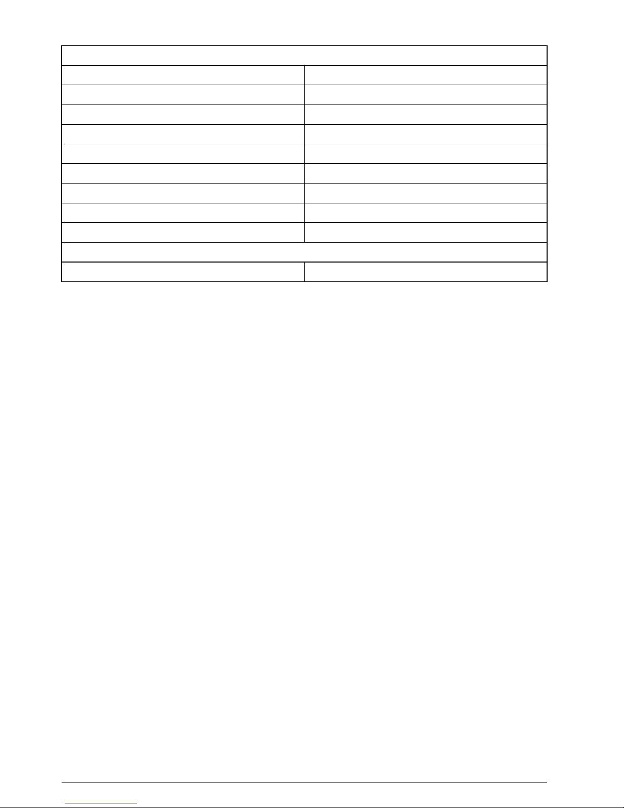
Table 2 Calibration and instrument data
Calibration data
Calibration number Cal 1 value
Cal 1 mV value Cal 1 temperature
Cal 2 value Cal 2 mV value
Cal 2 temperature Cal 3 value
Cal 4 value Cal 4 mV value
Cal 5 mV value Cal 5 temperature
Slope cal 1 to cal 2 Slope cal 2 to cal 3
Slope cal 3 to cal 4 Slope cal 4 to cal 5
Cal date Cal time
Instrument data
Meter serial number Probe serial number (ISFET only)
Recall a calibration
1. In the measurement mode, push RECALL.
2. Push CAL to read calibration data. The last calibration data location shows.
3. Push RECALL to read the data.
4. To select a different data location, use the numeric keypad to enter the location number, then
push ENTER.
5. The first calibration point for the calibration in storage shows. Use the arrow keys to read other
calibration points in storage.
6. Push ENTER to see the mV value of the calibration point in storage.
7. Push ENTER to see the slope of the calibration in storage.
8. Push RECALL or CANCEL
to go back to the pH calibration values in storage.
9. Push TIME to see the time of a calibration in storage.
10. Push TIME again to see the date of a calibration in storage.
11. Push pH, ISE, COND, TDS, SAL or DO or CANCEL to go back to measurement mode.
Set a passcode
Set a passcode for authorized personnel to access calibration methods or other functions.
Note: To use setup functions without a passcode, set the passcode to 0000.
1. Push SETUP to put the meter in setup mode.
2. Use the arrow keys until the PASSCODE and SETUP shows on the display.
3. Push ENTER. The display prompts to change the passcode. The default is "NO."
4. Use the arrow keys to select "YES." Push ENTER.
5. Use the number keys to enter a passcode. Push ENTER to keep the changes and go back to
setup mode.
Note: To exit and not keep the changes, push CANCEL.
Note: Wait 5 minutes for the meter to set the new passcode, or set the meter power to off, then back on. The
meter will prompt for the new passcode.
18 English
Page 21

Change a passcode
To change a set passcode, first make sure that the passcode is set. Refer to Set a passcode
on page 18.
1. Push SETUP to put the meter in setup mode.
2. Use the arrow keys to enter the four-digit passcode.
3. Push ENTER.
4. If the passcode is not correct, the display shows "Err."
5. Push CANCEL
to enter the correct passcode, or push pH, mV, ISE, TDS, COND, SAL or DO to
go back to measurement mode.
Note: Contact technical support if the user or the system administrator cannot enter the correct passcode.
Override an error
The user can override some errors (e.g., poor electrode condition) until a replacement electrode is
ordered and received.
Note: It is not possible to override all errors. The manufacturer does not recommend that the user override error
codes. Contact technical support to override error codes.
To cancel or override an error:
1. Find the cause of the error. Refer to Error codes on page 29. If possible, push CANCEL or pH,
COND, TDS or DO to cancel the calibration or other error.
2. To override the error, do not complete step 1. Instead, push ENTER.
3. Use the arrow keys until "YES" shows.
4. Push ENTER.
Advanced operation
Set the pH operations
Set the calibration alarm, the pH resolution, the calibration points and the calibration methods. Do the
operations in order.
1. Set the power to on.
2. Push SETUP, then pH.
3. Use the arrow keys to select an option, then push ENTER:
Operation Function
pH calibration alarm Sets the alarm from 1 to 999 hours. The recalibration alarm is set to "OFF" at
000 hours.
pH resolution Sets the pH resolution to 0.1 or 0.01 pH. The stabilization lock (the "READY" icon) is
faster at a 0.1 pH resolution.
Set the 2, 3, 4 or 5-point
pH calibration
Shows the current number of calibration points. Use the arrow keys to set the
calibration points.
pH calibration method
• Selects the pH buffer to use and in what order. The default is a 2-point calibration
(pH 7.00, then 4.00).
• Shows the pH buffer for the first calibration point.
• Changes other buffer values to set the pH calibration method until all buffers are
set.
Note: Previously-set buffers will not be shown.
4. Push ENTER to keep the changes and go back to setup mode.
Note: To exit and not keep the changes, push CANCEL.
English 19
Page 22

Set the manual temperature compensation
Glass pH electrodes are automatically temperature compensated if a temperature probe is sensed in
the 3.5 mm phono jack. If no probe is sensed, the meter defaults to the manual temperature
compensation at 25.0 ºC. Manual temperature compensation is always in ºC. Refer to Set the
manual temperature compensation for glass electrodes.
pH buffer values at various temperatures
25 ºC 0 ºC 5 ºC 10 ºC 20 ºC 30 ºC 40 ºC 50 ºC
1.68 1.67 1.67 1.67 1.67 1.68 1.69 1.71
4.01 4.00 4.00 4.00 4.00 4.01 4.03 4.06
6.86 6.98 6.95 6.92 6.87 6.85 6.84 6.83
7.00 7.12 7.09 7.06 7.01 6.99 6.97 6.97
9.18 9.46 9.40 9.33 9.23 9.14 9.07 9.02
10.01 10.32 10.25 10.18 10.06 9.97 9.98 9.83
12.45 13.42 13.21 13.00 12.63 12.29 12.04 11.70
1. Push SETUP, then pH to put into pH setup mode.
2. Use the arrow keys until the manual temperature shows "- - -.- ºC" on the display.
3. Push ENTER to see the manual temperature value.
4. Use the arrow keys to set the manual temperature compensation.
5. Push ENTER to keep the changes and go back to setup mode.
Note: To exit and not keep the changes, push SETUP.
Calibrate for pH measurement
The meter accepts 1, 2, 3, 4 and 5-point calibrations. The default is a 2-point calibration. If
necessary, a system administrator or a user can set the sequence of buffers and numbers of
calibration points.
1. Push pH to put the meter in pH mode.
*
2. Put the probe in the buffer solution.
Note: To erase all previous calibration points, slopes and offset, push CAL, then DELETE. To update a
previous calibration with a single-point calibration, ignore this step.
3. Push CAL, then the "CAL" icon flashes on the display.
Note: The user can stop a calibration when the pH value is in flash mode. Push pH or CANCEL to go back to
the measurement mode.
4. If the buffer is not correct, push ENTER, then the pH buffer flashes on the main display until the
calibration is complete.
5. If the pH buffer is incorrect, use the arrow keys to select another buffer.
6. Use the arrow keys to see the buffers: 1.68, 4.01, 6.86, 7.00, 9.18, 10.01 and 12.45. During "CAL
2" or "CAL 3", the meter ignores the values used in previous calibrations.
7. The meter beeps three times when a calibration is complete. CAL 3 and the next pH buffer value
(the default is 4.01) flashes on the display.
8. Rinse the probe in deionized water and put in the second buffer solution.
*
The slope is the change in potential when the pH reading changes by one decade, (e.g., from pH
7.00 to pH 8.00). The % slope is the ratio of the measured slope and the theoretical Nerst slope
of 59.16 mV per decade of pH change at 25 ºC. If the slope on a BNC electrode is not between
85 to 102%, the meter shows the error code: E04. If the calibration is more than two points, the
slope that shows is the average slope for all points. The meter will show E03, if the offset from
0.0 mV in pH 7.00 is larger than ±30 mV. Refer to Error codes on page 29.
20 English
Page 23

9. Push ENTER, if OK or use the arrow keys to change the value. Push the pH to accept a 1-point
calibration and to go back to the pH measurement mode.
If ENTER is selected, then the buffer value flashes until calibration is complete.
10. If the meter is set for a 2-point calibration, the meter beeps three times when the calibration is
complete. The display shows the slope, the mV offset at pH 7.00 and the number of calibration
points. Review the calibration data, then push pH or STORE
to start reading the pH value of any
solution.
11. If the meter is setup for three or more calibration points, then do steps 1 through 9 again until the
final calibration points are complete.
Set the ISE operations
Set the calibration alarm, the 2, 3, 4 or 5-point calibration and the calibration method. Do the
operations in order.
1. Set the power to on.
2. Push SETUP, then ISE to put the meter in ISE setup mode.
3. Use the arrow keys to select an option, then push ENTER:
Operation Function
ISE calibration alarm Sets the alarm from 1 to 999 hours. The recalibration alarm is set to "OFF" at 000 hours.
2, 3, 4 or 5-point ISE
calibration
Shows the current number of calibration points. Use the arrow keys to set the calibration
points.
ISE calibration
method
• Selects the ISE standard to use and specifies the order.
• Shows the numeric entry screen. Push TIME two times to toggle between ppm or ppt
resolution.
• Use the arrows or the numeric keypad to enter the first ISE calibration standard.
• Do these steps again for each calibration point.
Note: Exit the setup mode and go to ISE calibration mode to view calibration values in storage. Use
the arrow keys to view all calibration values in the current setup method.
4. Push ENTER to keep the changes and go back to setup mode.
Note: To not save the changes and exit, push CANCEL.
Calibrate for ISE measurement
The meter accepts up to five ISE calibration standards. The values of the concentration standards
are first entered in the setup mode.
1. Set the power to on.
2. Push ISE to put the meter in the ISE mode.
Note: Push CANCEL at any time to stop calibration.
3. Put the probe in the first calibration solution.
4. To erase all previous calibration points, slopes and offset values, push CAL, then DELETE.
5. To update a previous calibration with a single point calibration, do not erase all previous
calibration points, slopes and offset values.
6. Push CAL. The "CAL 1" icon flashes.
7. Use the arrow keys to select the concentration of the ISE standard.
8. Push ENTER to start the calibration.
9. The meter beeps three times when the first calibration is complete. "CAL 2" and the next ISE
concentration value flashes on the display.
10. Rinse the probe in deionized water. If necessary, put the probe in the next calibration solution.
Repeat steps 2 to 10 until calibrations are complete.
English 21
Page 24
Set the conductivity options
Set the calibration alarm, the conductivity temperature compensation, the 2, 3, 4 or 5-point
conductivity calibration, the conductivity temperature and the cell constant.
1. Set the power to on.
2. Push SETUP, then COND to put the meter in conductivity setup mode.
3. Use the arrow keys to select an option, then push ENTER:
Operation Function
ISE calibration alarm Sets the alarm from 1 to 999 hours. The recalibration alarm is set to "OFF" at
000 hours.
Conductivity temperature
compensation
• Use the arrow keys to set the compensation coefficient between 0 to 10 (the
default is set to 2% per ºC).
• Conductivity is automatically temperature compensated.
2, 3, 4 or 5-point
conductivity calibration
• Use the arrow keys to select each option, then push ENTER:
• Shows the first active calibration point. Use the arrow keys to see other in-use
values.
Note: "- - - -" shows on the display if there are no conductivity calibration points in storage.
Conductivity
temperature
1
• Shows the conductivity normalization value.
• Use the display settings between 20 to 25 °C (default = 25 °C).
Conductivity probe cell
constant
The cell constant is automatically found and shows on the display. Sets the cell
constants to:
• K = 0.5 for general procedures
• K = 1 for low conductivity procedures (e.g., drinking water)
• K = 10 for salinity or brackish water
• If no conductivity probe is attached, the display shows "000."
1
Conductivity varies a lot with temperature. The Automatic temperature compensation (ATC) adjusts
conductivity measurements to calculate the conductivity changes in the reading that are caused by
temperature. The readings are referenced to or "normalized" at a standard temperature. The ATC gives the
equivalent conductivity or TDS of a solution normalized at 20 or 25 °C.
4. Push ENTER to keep the changes and go back to setup mode.
Note: To exit and not keep the changes, push CANCEL.
Set the TDS options
Set the TDS conversion factor, the TDS units and the salinity units. Complete the operations in order.
1. Set the power to on.
2. Push SETUP, then ISE to put the meter in ISE setup mode.
3. Use the arrow keys to select an option, then push ENTER:
Operation Function
TDS conversion factor
• TDS values are related to conductivity. Calibrate with a TDS standard or with
conductivity standards, then program the meter with a conversion factor.
• Sets the conversion factor to 0.40 to 1.00 (default is set to 0.50).
TDS units Use the arrow keys to set the TDS units in mg/L (g/L) or ppm (ppt).
Salinity units in ppm (ppt)
or %
Use the arrow keys to set the salinity units in ppm (ppt) or as a percentage.
22 English
Page 25

4. Push ENTER to keep the changes and go back to setup mode.
Note: To exit and not keep the changes, push CANCEL.
Calibrate for conductivity and TDS measurement
Calibrate the meter with up to five calibration points with conductivity or TDS standards. If the
calibration point is 20% larger than a calibration point in storage, both conductivity points are kept. If
the calibration point is 20% smaller than a calibration point in storage, only the new calibration point
is kept. If there are five calibration points in storage, the new calibration data replaces values near
the same range.
By default, the meter uses the temperature coefficient of 2% per °C. The user can set the coefficient
in setup mode. Review calibration points in setup mode.
Note: Salinity measurements are identified from conductivity.
1. Set the power to on.
2. Push COND or TDS.
3. Put the probe in the first standard solution. The meter measures the standard.
4. Use the arrow keys to select the value of the conductivity or TDS standard.
5. Push ENTER. The main display shows, then the "WAit" icon flashes.
Note: Push TDS or COND to stop calibration. The meter stops the current calibration and keeps the previous
calibration data.
6. Push CAL. The main value flashes.
7. To erase all previous calibration points, slopes and offset values, push CAL, then DELETE.
Ignore this step to update a previous calibration with a single point calibration.
8. Push COND or TDS to read the conductivity or TDS value of any solution.
9. Do steps 2 through 9 again to complete multiple calibration points (maximum of 5).
10. When the calibration is complete, the meter shows the slope as compared to the nominal
sensitivity for a probe of that cell constant and the total number of conductivity and TDS
calibration points in the meter.
Note:
The number at the bottom right corner of the display is the calibration points that are in the meter. The
value above the slope is the slope relative to the nominal sensitivity.
Set the DO operations
Use the steps that follow to set: the calibration alarm, the measurement units, the calibration units,
1 or 2-point calibration points and the calibration methods. Make sure that the operations are
completed in order.
Note: If the DO calibration units are changed in setup, (e.g., from % to ppm), the meter automatically changes the
values entered when the calibration method is setup to the selected units. Since the conversions are approximate,
for maximum accuracy, enter the necessary values in this procedure in the correct calibration units.
1. Set the power to on.
2. Push SETUP, then DO to put the meter in DO mode.
3. Use the arrow keys to select an option, then push ENTER:
Operation Function
DO calibration alarm
• Sets the alarm from 1 to 999 hours. The recalibration alarm is set to OFF at 000 hours.
• Push ENTER to go back to setup mode.
• Push ENTER, then DO.
• Use the arrow keys until "Unit" shows.
Measurement units Use the arrow keys to set the DO measurement units (mg/L, %, salinity or ppm).
Calibration units Use the arrow keys to set the DO calibration units (mg/L, % or ppm).
English 23
Page 26
Operation Function
1 or 2-point
calibrations
• The default calibration point is set to one at 100% saturation.
1
• Use the arrow keys to set the calibration point to 1 or 2.
• After this data is kept or cancelled, the display shows the current number of calibration
points.
Calibration method
• Use the arrow keys to set the first calibration standard.
• If the meter is setup for two DO points, do these steps again for the second calibration
point.
Note: If the DO calibration units are changed in setup, (e.g., from % to ppm), the meter automatically
changes the values entered in this step to the selected units. Since the conversions are approximate,
enter the necessary values in this procedure (for maximum accuracy) in the correct calibration units.
Note: DO calibrations are not salinity compensated. The salinity value from an attached salinity probe or
the salinity value entered in setup will be ignored.
1
This assumes a nominal slope of 47 mV from 0% to 100% at 25 ºC at 1013 hPa barometric pressure with
0 ppm salinity.
4. Push ENTER to keep the changes and go back to setup mode.
Note: To exit and not keep the changes, push CANCEL.
Set the Barometric pressure compensation units
DO measurements are sensitive to barometric pressure. The meter has a built-in barometer to give
automatic compensation of barometric pressure.
The meter shows barometric pressure in Hg (inches of mercury), mmHg (millimeters of mercury), or
hPa (hectopascals or millibars). The default unit is set to hPa.
1. Set the power to on.
2. Push SETUP, then DO to put the meter in the DO setup mode.
3. Use the arrow keys until "bAr Unit" shows on the display.
4. Push ENTER, then use the arrow keys to set the barometric pressure units (hPa, mmHg and
inHg).
5. Push ENTER
to keep the changes and go back to setup mode.
Note: To exit and not keep the changes, push CANCEL.
6. Next, use the numeric keypad or the arrow keys to set the salinity compensation value.
7. Push ENTER to keep the changes and go back to setup mode.
Note: To exit and not keep the changes, push CANCEL.
Calibrate for DO measurement
Calibrate the H280G and H280GB benchtop meters to measure DO with two methods: the watersaturated air method or the water sample with a known DO concentration method.
Up to two calibration points can be done at any concentration. If a 1-point calibration is done, the
meter replaces the calibration point in storage that is most near the new calibration point (e.g., a new
100% DO single-point calibration replaces the calibration point in storage that is closest to a 100%
DO value). Both methods can do 1-or-2-point calibrations. During setup, calibration and
measurement units can be set to % or mg/L.
N O T I C E
DO is related to barometric pressure. The meter has a built-in barometer that will do automatic compensation for
barometric pressure.
Note: Do not set the power to off and remove the probes during conductivity or DO modes because the meter will
show an error the next time the meter is set to power on. Exit conductivity or DO modes before shutdown.
Calibrate with a known concentration method
To measure DO, make sure that the concentration is already known.
24 English
Page 27

Note: Put the probe into an oxygen-scavenging solution (e.g., a 2% sodium sulfite for 5 minutes) to get a near-zero
DO solution.
1. Set the meter power to on.
2. Use the arrow keys to select the DO standard concentration.
3. Push ENTER to start the calibration.
Push CANCEL at any time during calibration to exit. The meter stops the current calibration and
keeps the old calibration data.
4. The DO value and "WAit" flashes until the calibration is complete.
5. The meter beeps three times when the first point of the calibration is complete.
6. If setup for a 1-point calibration, the meter shows the slope. Push DO or STORE to go to the
measurement mode.
7. If setup for a 2-point calibration, the next DO concentration value (specified in setup) and "CAL 2"
flashes.
8. Push ENTER to start the calibration. The DO value and "WAit" flashes until calibration is
complete. When the calibration is complete, the slope shows on the display.
9. To do only a 1-point calibration, push DO or STORE. The meter will accept just a 1-point
calibration and show the slope. If not, continue to the next step.
10. Push BAR to see barometric pressure. Push SAL to see the measured salinity adjustment, if a
conductivity (salinity) probe is attached. If no conductivity probe is attached, the manual salinity
compensation factor shows on the display.
Calibrate with an air-saturated method
Refer to Configure the meter on page 14 to set the calibration and measurement units to % or mg/L.
Do the operations in order:
1. Prepare the first standard. Put 1 cc of water in a narrow-necked bottle and shake vigorously.
2. Clean the probe tip dry, then put the probe in the bottle.
3. For a quick method: Wet the probe membrane with water, then hold the probe in the air with the
sensor pointed to the ground.
Note: Slope is the ratio of the actual mV output of the sensor as compared to the nominal sensitivity of 0.0 mV
at 0% saturation and 45.0 mV at 100% (i.e., 100% = 8.2 mg/L saturation at 25 °C at 1013.25 hPa barometric
pressure at 0 ppm salinity). 1 mg/L = 1 ppm. The nominal slope is 8.2 ppm/45mV or 0.1822 ppm per mV.
4. Set the meter power to on.
5. Push DO to put the meter in DO mode. The meter reads the DO value.
Push CANCEL during calibration to exit. The meter stops the current calibration and keeps the
old calibration data.
6. Put the probe in the first calibration solution or the saturated air bottle.
To erase all previous calibration points, slopes and offsets, push CAL, then DELETE.
To update a previous calibration with a 1-point calibration, ignore this step.
7. Push CAL, then the "CAL" icon flashes.
Maintenance
Replace the batteries
The display shows "bAt" when the batteries are too low to give a reliable measurement. The low
battery icon (refer to Display description on page 13) shows when there is approximately 25 hours of
battery power. Measurement errors are possible when the batteries are low. Refer to Install the
batteries on page 10 to replace the batteries.
Note: The date and time must be set again when the batteries are removed or are fully discharged.
Clean the instrument
Clean the exterior of the instrument with a moist cloth and a mild soap solution and then wipe the
instrument dry.
English 25
Page 28

ISFET pH probe maintenance
C A U T I O N
Multiple hazards. Only qualified personnel must conduct the tasks described in this section of the
document.
C A U T I O N
Chemical exposure hazard. Obey laboratory safety procedures and wear all of the personal protective
equipment appropriate to the chemicals that are handled. Refer to the current safety data sheets
(MSDS/SDS) for safety protocols.
The expected life of an ISFET probe is approximately 18 months. The reference electrode has a KCI
gel that is diluted over time. The reference is sealed and is non-refillable. Replace the probe when it
becomes difficult to calibrate.
•
Keep the probe dry with the protective shroud on when not in use.
•
Clean oil, fat, food particles, starch, protein or other materials from the probe tip after use.
•
Never use sharp metal objects (e.g., a needle, a pin, etc.) to clean the sensor surface.
•
Remove the probe from environments with static electricity. Electrostatic discharge (ESD) can
permanently damage the probe.
•
Remove the probe from environments that will damage the sensor, such as hydrofluoric acid or
abrasive samples.
• Remove the probe from environments that will damage the epoxy materials used in the probe tip
(e.g., keep the probe away from acetone, toluene, methylene chloride, xylene and other strong
organic solvents).
• Do not use the probe in temperatures more than 60 ºC (140 ºF). Thermal cycling can decrease the
life of the probe.
• For semi-solids use, carefully twist the probe to make sufficient contact with the sample to the
sensor.
• When semi-solids are tested, make sure that solid objects (i.e., bone or gristle) do not scratch the
sensor.
• Cool samples to room temperature to maximize probe life.
• Always use new buffers and new rinse solutions.
Prepare the probe for storage
N O T I C E
Do not use the probe for long-term pH measurement applications.
Note: No electrode storage solution is necessary.
A new probe usually has visible reference gel at the tip of the probe, as well as in the interior of the
rubber dust cap. To remove the gel, carefully clean with a soft-bristled toothbrush and mild soapy
water (a few drops of dish soap in a warm cup of water). The gel can continue to show for two to five
days. Do not put the rubber dust cap on the probe until all of the reference gel is removed. Do not
complete the steps that follow until all reference gel is removed from the probe and the interior and
exterior of the rubber dust cap.
Prepare the probe for storage
1. Put the new probe (or the probe that was in extended storage) in pH 7 buffer for at least
5 minutes.
2. Stir the probe in pH 7 buffer solution to dislodge air bubbles.
3. Use fresh deionized water to rinse the probe.
4. Dry the probe with a lint-free cloth.
26 English
Page 29

5. Put the rubber dust cap back on.
6. Keep the probe in dry storage when not in use.
Calibrate the ISFET probe
Refer to Prepare the probe for storage on page 26 before calibration.
N O T I C E
Do not use the probe for applications that cycle between hot and room temperature samples.
Note: Remove other active or non-active measurement devices during pH or conductivity measurement. Other
devices, even AC power, can cause interference.
Note: Only do calibrations away from the sun. Direct sunlight can cause unstable readings or difficulty in
calibration.
1. Connect the probe to the meter.
2. Set the meter power to on.
3. Clean the probe with new deionized water and dry with a lint-free cloth.
4. Put the probe in the pH 7 buffer.
5. Clean the probe with deionized water and dry with a lint-free cloth.
6. Put the probe in the second buffer (pH 4 or pH 10).
7. Read the results.
8. If the result is not correct, the probe is not correctly hydrated.
Soak the probe for another 5 minutes in pH 7 buffer, then do the calibration again.
Clean the ISFET probe
N O T I C E
Do not use sharp metal objects (a needle, a pin, etc.) to clean the sensor. This can scratch the sensor and cause
permanent damage to the probe.
For use in dairy, cheese or meat applications, soak the probe in Pepsin Cleaning Solution for
15 minutes before the probe is cleaned.
Regularly clean a non-glass probe:
1. Remove the rubber dust cap from the probe, then rinse with new deionized water.
2. Use a soft-bristle toothbrush and a mild detergent (a few drops of dish soap in a warm cup of
water) to carefully clean the probe.
3. Rinse with new deionized water to remove all debris from the sensor surface.
4. Dry the probe with a lint-free cloth.
5. Calibrate the probe again. Refer to Calibrate the ISFET probe on page 27, then Prepare the
probe for storage on page 26.
Repair the ISFET probes
N O T I C E
Do not use the probe to find out if the buffer is above 60 °C (140 °F). If the probe is suddenly put into very hot
liquid, the probe can be permanently damaged.
Monitor how long the probes are in dry storage. If the probes are in storage for an extended period of
time, the KCI gel at the reference junction can crystallize.
1. Heat pH 7 buffer to approximately 45 to 60 °C (115 to 140 °F).
2. Soak the probe for 2 minutes.
3. Put the probe in room temperature pH 7.00 buffer and let cool.
English 27
Page 30
BNC electrode maintenance
Prevent unstable readings:
• Keep the probe in an electrode storage solution.
• Start measurements with at least a 2-point calibration. Update often with 1, 2 or 3-point
calibrations.
• Use new buffers and new deionized rinse solution.
• Use buffer solutions with pH values no larger than 3 pH units apart. Ideally, the buffers bracket the
anticipated pH values of the unmeasured samples.
•
Use deionized water to rinse residual buffer and sample solutions from the probe after calibration
and measurement.
• Calibrate at the same temperature as the sample solution. Although the meter has an ATC, get the
best results when the calibration buffers and the sample are the same temperature.
• Keep the connectors clean and dry. Dirty or damp connectors can cause unstable readings.
Clean the electrode
N O T I C E
Never use sharp metal objects (e.g., a needle, a pin, etc.) to clean the sensor surface. The sensor can be
permanently damaged with abrasion of the sensor surface.
Clean the electrode with a soft-bristled toothbrush and mild soapy water (a few drops of soap in
warm water).
Troubleshooting
Problem Possible cause Solution
No display Automatic shutdown set the
power to off.
Set the power to on again.
There is no power. Replace the batteries.
Unstable reading The probe is dirty. Clean the probe.
The probe or the meter
connectors are dirty.
Clean the probe contacts on the cable
connector. Clean the meter with
methanol on a cotton swab. Let dry
completely. Connect the probe to the
meter again.
No flow in the reference junction Clean the warm buffer.
ISFET probe is not correctly
hydrated.
Soak the probe for at least 5 minutes
in a pH 7.00 buffer.
Interference from other devices Remove other devices from the
solution.
Interference from direct sunlight Use protection for the probe from
direct sunlight.
The probe is in a very low ionic
strength solution.
A stable reading is not possible.
The pH or temperature of the
solution changes.
A stable reading is not possible until
pH and temperature are constant.
28 English
Page 31

Problem Possible cause Solution
The meter continually
shows –2.00 or 19.99 with an
electrode attached. The "ISFET" icon
does not show when ISFET probe is
attached.
The ISFET probe is not sensed
by the meter or the probe.
Set the meter power to off. If the
"ISFET" icon does not show, replace
the ISFET probe.
Out of calibration Calibrate the ISFET probe
on page 27.
The probe is not in the solution. Put the probe in liquid. Carefully
shake the probe to make sure that air
bubbles are not caught on the sensor
surface.
No probe is connected to the
meter.
Set the meter power to off. Connect
the pH probe. Set the meter power to
on.
The probe is dirty. Clean the probe.
The probe is damaged. Replace the probe. Contact technical
support.
Screen flashes during calibration. The probe sensor surfaces are
dirty or it is necessary for the
probe to be conditioned again.
Clean and condition the probe again.
No flow in the reference junction Clean the warm buffer.
The buffers are contaminated or
expired.
Calibrate with new buffers again.
Interference from other devices in
the solution
Remove all devices from the solution.
The battery is low. Replace the batteries if the battery
icon shows low battery power.
Interference from direct sunlight Use protection for the probe from
direct sunlight.
The probe is too old. Replace the probe.
Error codes
Table 3 shows the codes that can occur for various reasons. Error codes show instrument
malfunction or user error.
Table 3 Error code descriptions
Error
Code
Description Solution
E02 The ISFET pH probe is damaged. Replace the probe. Contact technical support for probe
replacement information.
E03 Clean the probe. Clean the probe. If the error continues, replace the probe.
E04 Glass pH probe slope error. The
slope is smaller than 85% or larger
than 102% of 59.16 mV per pH unit.
Clean the probe. If the error continues, replace the probe.
E06 ISFET pH probe slope error. Clean the probe. Soak in 40 ºC (113 ºF) pH 7.00 buffer for
2 minutes. Calibrate again. If the error continues, replace the
probe.
E07 Clean the probe. Clean the probe. Make sure that no air bubbles on the sensor
surface or foreign objects or materials on the sensor.
English 29
Page 32
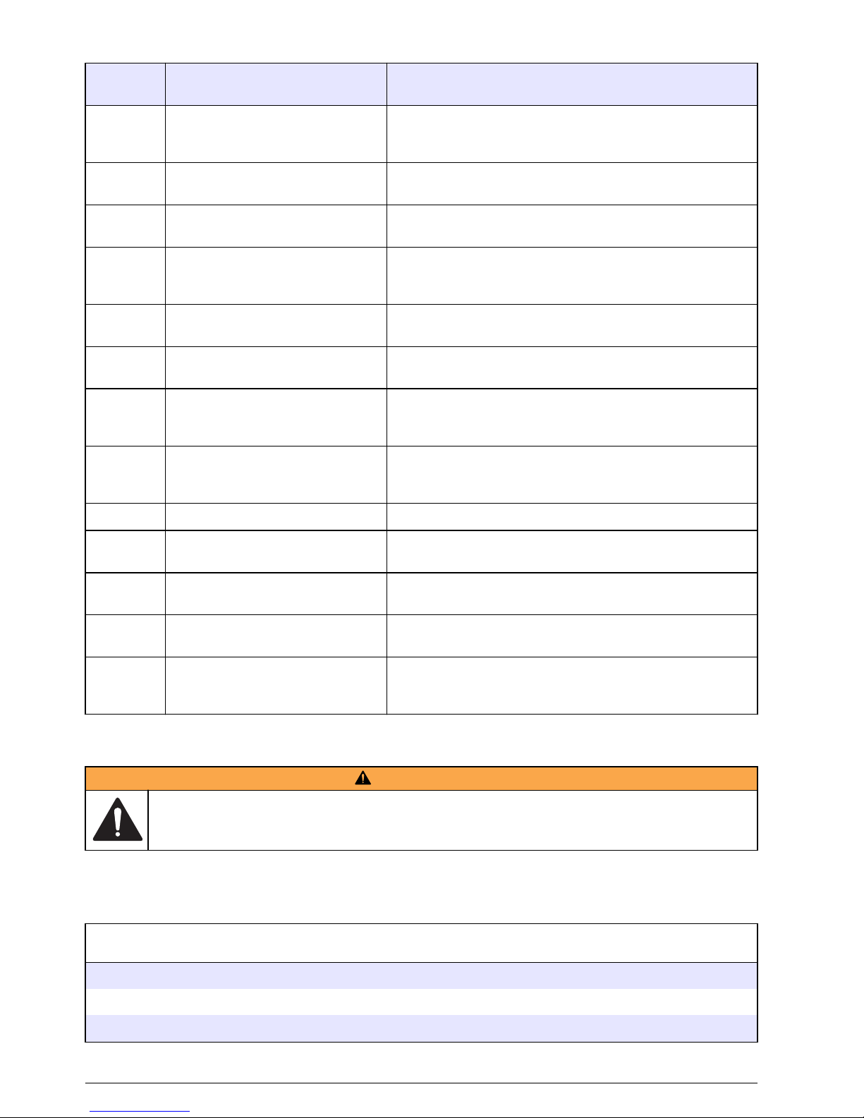
Table 3 Error code descriptions (continued)
Error
Code
Description Solution
E08 Too long to calibrate. Signal is not
stable during calibration.
Clean the probe. Disconnect stirrers and other AC power
sources. Make sure that the calibration solution temperature
is constant. Replace the probe if the error continues.
E13 The ISFET pH probe temperature
sensor is damaged.
Replace the probe. Contact technical support for probe
replacement information.
E14 The battery is extremely low. Replace the batteries immediately. Damage to the accuracy
and function of the meter could have occurred.
E15 Replace the battery immediately.
The accuracy and function of the
meter could be compromised.
Contact technical support for service information.
E20 The conductivity temperature
sensor is damaged.
Replace the probe. Contact technical support for probe
replacement information.
E25 The slope is smaller than 60% or
larger than 140% of the nominal.
Replace DO probe membrane and fill solution. Replace the
probe if the error continues. Nominal = 0.1822 ppm/mV.
E26 The mV reading is more than
±10 mV from nominal.
Replace DO probe membrane and fill solution. Replace the
probe if the error continues. Nominal = 0.0 mV at 0%
saturation; 45mV at 100%.
E27 DO probe temperature error Attach the temperature sensor to the 3.5 mm phono jack. DO
readings are highly temperature dependent and a
temperature sensor must be attached.
E28 Barometric pressure sensor error Contact technical support for repair information.
E30 ISE electrode calibration error The slopes are not the same sign or are not within 25% of
each other. Calibrate again in the correct solutions.
E40 Unrecognized host command Command from a host PC is not found. Use only valid
commands.
E42 Invalid input The value entered during the setup is invalid. Enter a
different value.
E44 No probe is installed No probe is installed for the applicable parameter. Set the
meter power to off. Install the correct probe. Set the meter
power to on.
Replacement parts and accessories
W A R N I N G
Personal injury hazard. Use of non-approved parts may cause personal injury, damage to the
instrument or equipment malfunction. The replacement parts in this section are approved by the
manufacturer.
Note: Product and Article numbers may vary for some selling regions. Contact the appropriate distributor or refer to
the company website for contact information.
Replacement parts
Description Quantity Item no.
AA Alkaline batteries 4 1938004
USB cable assemblies, A-B, 28/26, black 1 10013Q
Power supply, 100–240 VAC 1 8522400
30 English
Page 33

Accessories
Description Quantity Item no.
ISFET pH probes for the handheld meters
1
General purpose round tip pH probe 1 PHW77-SS
Micro pH probe 1 PHW17-SS
Piercing tip micro pH probe 1 PHW37-SS
pH probe for NMR tubes 1 PHW47-SS
Heavy duty piercing tip micro pH probe 1 PHW57-SS
ISFET pH probes for the benchtop meters
General purpose round tip pH probe 1 PH77-SS
Micro pH probe 1 PH17-SS
Piercing tip micro pH probe 1 PH37-SS
pH probe for NMR Tubes 1 PH47-SS
Heavy duty piercing tip micro pH probe 1 PH57-SS
Conductivity and dissolved oxygen probes
General purpose conductivity probe, epoxy, K = 0.5 4 graphite contacts CDW97-KP5
LIS conductivity probe, glass, K = 1 4 platinum contacts CDW97-K1
Conductivity probe for salinity and brackish water, epoxy, K =
10
4 contacts CDW97-K10
Glass pH probes
Gel-filled combination pH, BNC and 3.5 mm phone 1 5193511
Pt Series combination pH, BNC and 3.5 mm phone 1 5191011
Refillable combination pH, BNC and 3.5 mm phone 1 5194011
1
These ISFET pH probes are for both handheld and benchtop meters and are stainless steel.
Consumables
Description Quantity Item no.
Probe cleaning solution for removal of protein deposits on pH probes 500 mL 2964349
Rinse solution, non-ionic surfactant 500 mL 2964449
Buffer solution, red, pH 4.01 500 mL 2283449
Buffer solution, yellow, pH 7.00 500 mL 2283549
Buffer solution, blue, pH 10.01 500 mL 2283649
Conductivity standard solution, 100 μS/cm 500 mL 2971849
Conductivity standard solution, 1000 μS/cm 500 mL 1440049
Conductivity standard solution, 10,000 μS/cm 500 mL 2972249
Conductivity standard solution of 35 ppt salinity, 53 mS/cm 500 mL 2714349
Conductivity standard solution, 100 μS/cm 100 mL 2971842
Conductivity standard solution, 1000 μS/cm 100 mL 1440042
English 31
Page 34

Consumables (continued)
Description Quantity Item no.
Conductivity standard solution, 10,000 μS/cm 100 mL 2972242
Easy-to-thread-on cap with a pre-installed membrane 1 DO50-CAP
DO50-KIT, includes: DO50-CAP, electrolyte and syringe 1 DO50-KIT
32 English
Page 35

Page 36

HACH COMPANY World Headquarters
P.O. Box 389, Loveland, CO 80539-0389 U.S.A.
Tel. (970) 669-3050
(800) 227-4224 (U.S.A. only)
Fax (970) 669-2932
orders@hach.com
www.hach.com
HACH LANGE GMBH
Willstätterstraße 11
D-40549 Düsseldorf, Germany
Tel. +49 (0) 2 11 52 88-320
Fax +49 (0) 2 11 52 88-210
info@hach-lange.de
www.hach-lange.de
HACH LANGE Sàrl
6, route de Compois
1222 Vésenaz
SWITZERLAND
Tel. +41 22 594 6400
Fax +41 22 594 6499
©
Hach Company/Hach Lange GmbH, 2013.
All rights reserved. Printed in U.S.A.
 Loading...