

Hach ORBISPHERE Series, GA2 00 Series, GA2800-SKS, GA2800-HVS, GA2400-S00 Basic User Manual
...Page 1
DOC024.98.93153
ORBISPHERE Model
GA2X00 O2 EC Sensor
11/2019, Edition 2
Allgemeines Benutzerhandbuch
Manuale di base per l'utente
Manuel d'utilisation de base
Manual básico del usuario
Basisgebruikershandleiding
Grundlæggende brugervejledning
Podstawowa instrukcja obsługi
Alapvető felhasználói kézikönyv
Basic User Manual
Allmän användarhandbok
Peruskäyttöohje
Page 2

Table of Contents
English..............................................................................................................................3
Deutsch.......................................................................................................................... 22
Italiano............................................................................................................................ 42
Français......................................................................................................................... 62
Español.......................................................................................................................... 83
Nederlands................................................................................................................. 103
Dansk............................................................................................................................123
Polski............................................................................................................................ 142
Svenska....................................................................................................................... 162
Suomi............................................................................................................................181
Magyar......................................................................................................................... 200
2
Page 3

Table of Contents
1 Table of contents on page 3
2 Specifications on page 3
3 Expanded manual version on page 6
4 General information on page 6
5 Installation on page 8
6 Maintenance on page 13
7 Troubleshooting on page 20
Section 1 Table of contents
Specifications on page 3 Maintenance on page 13
General information on page 6 Troubleshooting on page 20
Installation on page 8
Section 2 Specifications
Specifications are subject to change without notice.
2.1 Sensor specifications
Table 1 ORBISPHERE family of GA2X00 oxygen sensors
Specification Details—Non-ATEX sensors Details—ATEX sensors
Type Electrochemical oxygen sensor
Dimensions (Ø × L) 32 × 86.3 mm (1.26 × 3.40 in.)
Weight 300 g
Pressure resistence 40 bar maximum with default PPS collar (100 bar with stainless steel collar)
Materials Stainless steel Stainless steel or hastelloy
Sensor head: Kalrez® O-rings
Sensor bottom: Viton® O-rings
Other Smart capability Intrinsically safe
Certification CE CE, Ex II 1 G, Ex ia IIC T6
EPDM and Kalrez® O-rings
Sensor head: Kalrez® O-rings
1
Sensor bottom: Viton® O-rings or Kalrez® O-rings
Note: Unlike the GA2400 non-ATEX sensors, the intrinsically safe GA2800 ATEX sensors have no smart capability
to store calibration data. However, all GA2800 ATEX sensors have the ATEX conformity information engraved on
the sensor itself.
2.2 Sensor configurations
Table 2 Beverage
Application Sensor Membrane Cartridge Protection Cap
Beer with ORBISPHERE
3650 Portable
Beer in-line GA2400-S00 2952A-A 33051-SG
Wort in-line GA2400-S00 29552A-A 33051-S0
1
Viton and Kalrez are trademarks of DuPont Corporation.
GA2400-S00 2958A-A (optimized response
time)
2952A-A (optimized
maintenance interval)
33051-SP
English 3
Page 4

Table 2 Beverage (continued)
Application Sensor Membrane Cartridge Protection Cap
Wort with ORBISPHERE
3650 Portable and special flow
cell 32007W.xxx
ORBISPHERE 6110 Total
package analyzer (TPA)
De-aerated water GA2400-S00 2956A-A or 2952A-A 33051-S0
GA2400-S00 29552A-A 33051-S0
GA2400-S00T 2956A-A 33051-ST
33051-SG (if exposed to
CIP)
Table 3 Pure water applications (Power - Electronics)
Application Sensor Membrane Cartridge Protection Cap
On-line dissolved oxygen traces in pure water GA2400-S00 2956A-A 33051-S0
Dissolved oxygen traces with 3655 Portable GA2400-S00 2956A-A 33051-S0
Table 4 ATEX
Sensor Membrane Cartridge Protection Cap
GA2800-SVS 2956A-A or 29552A-A 33051-SG
GA2800--SKS 2956A-A or 29552A-A 33051-SG
GA2800--HVS 2956A-A or 29552A-A 33051-H0
GA2800--HKS 2956A-A or 29552A-A 33051-H0
2.3 Sensor membrane specifications
2.3.1 Oxygen sensors (Table 1)
Table 5 Membrane specifications - Oxygen sensors (1)
Specification 2956A-A 2958A-A 29552A-A 2952A-A
Recommended applications Corrosion control,
De-aerated water
Material PFA Tefzel®
Thickness [μm] 25 12.5 50 25
Calibration gas Air Air Air Air / Pure O
Dissolved measurement range 0 ppb to 20 ppm 0 ppb to 40 ppm 0 ppb to 80 ppm 0 ppb to 80 ppm
Gaseous measurement range 0 Pa to 50 kPa 0 Pa to 100 kPa 0 Pa to 200 kPa 0 Pa to 200 kPa
Accuracy The greater of
±1% of reading
or ± 0.1 ppb3,
or ± 1 ppb4,
or ± 0.25 Pa
Beverage,
Lab. applications
2
The greater of
±1% of reading
or ± 1 ppb,
or ± 2 Pa
In line wort,
Air/O2 injection,
Sewage treatment
PTFE Tefzel
The greater of
±1% of reading
or ± 2 ppb,
or ± 5 Pa
Corrosion control,
In line beverage,
De-aerated water
®
The greater of
±1% of reading
or ± 2 ppb,
or ± 5 Pa
2
2
Tefzel is a trademark of DuPont Corporation.
3
Accuracy is ± 0.1 ppb for 410, 510, 362x, 360x and 3655 instruments
4
Accuracy is ± 1 ppb for 366x and 3650 instruments
4 English
Page 5

Table 5 Membrane specifications - Oxygen sensors (1) (continued)
Specification 2956A-A 2958A-A 29552A-A 2952A-A
Integrated radiation dose limit
2 x 10
4
8
10
N/A 10
8
[rads]
Expected current in air @ 1 bar
26.4 9.4 6.3 5.4
25 °C [μA]
Expected current in pure O2 [μA] 132 47 31.4 27
O2 consumption in O2 saturated
40 14 9.4 8
water at 25 °C [μg/hour]
Temp. compensation range – 5 to 60 °C
Temp. measuring range – 5 to 100 °C
Response time
Recommended min. liquid flow
5
7.2 sec. 9.5 sec. 90 sec. 38 sec.
180 120 50 50
rate6 [mL/min]
Recommended min. linear flow
200 100 30 30
rate6 [cm/sec]
Recommended gaseous flow rate
0.1 to 3
[L/min]
2.3.2 Oxygen sensors (Table 2)
Table 6 Membrane specifications - Oxygen sensors (2)
Specification 2935A-A 29521A-A 2995A-A
Recommended applications Saturated to super
saturated levels
Material Halar®
7
Thickness [μm] 25 125 12.5
Calibration gas Air / Pure O
2
Dissolved measurement range 0 ppb to 400 ppm 0 ppb to 400 ppm 0 ppb to 2000 ppm
Gaseous measurement range 0 Pa to 1000 kPa 0 Pa to 1000 kPa 0 Pa to 5000 kPa
Accuracy The greater of
±1% of reading
or ± 10 ppb,
or ± 20 Pa
Integrated radiation dose limit [rads] N/A 10
Expected current in air @ 1 bar
0.9 0.7 0.2
25 °C [μA]
Expected current in pure O2 [μA] 4.7 3.8 0.9
O2 consumption in O2 saturated
1.4 1.3 0.3
water at 25 °C [μg/hour]
Temp. compensation range – 5 to 60 °C
Saturated to super
saturated levels
®
Tefzel
Air / Pure O
2
The greater of
±1% of reading
or ± 10 ppb,
or ± 20 Pa
8
In line hot wort
(up to 70 °C)
®
Tefzel
Pure O
2
The greater of
±1% of reading
or ± 50 ppb,
or ± 100 Pa
8
10
5
Response time at 25 °C for a 90% signal change
6
Liquid flow through an ORBISPHERE 32001 flow chamber, with protection cap and no grille
7
Halar is a trademark of Solvay Corporation.
English 5
Page 6
Table 6 Membrane specifications - Oxygen sensors (2) (continued)
Specification 2935A-A 29521A-A 2995A-A
Temp. measuring range – 5 to 100 °C
Response time
Recommended min. liquid flow rate
[mL/min]
Recommended min. linear flow rate
[cm/sec]
Recommended gaseous flow rate
[L/min]
8
9
9
2.5 min. 18 min. 80 sec.
25 25 5
20 60 5
0.1 to 3
Section 3 Expanded manual version
For additional information, refer to the expanded version of this manual, which is available on the
manufacturer's website.
Section 4 General information
In no event will the manufacturer be liable for direct, indirect, special, incidental or consequential
damages resulting from any defect or omission in this manual. The manufacturer reserves the right to
make changes in this manual and the products it describes at any time, without notice or obligation.
Revised editions are found on the manufacturer’s website.
4.1 Safety information
N O T IC E
The manufacturer is not responsible for any damages due to misapplication or misuse of this product including,
without limitation, direct, incidental and consequential damages, and disclaims such damages to the full extent
permitted under applicable law. The user is solely responsible to identify critical application risks and install
appropriate mechanisms to protect processes during a possible equipment malfunction.
Please read this entire manual before unpacking, setting up or operating this equipment. Pay
attention to all danger and caution statements. Failure to do so could result in serious injury to the
operator or damage to the equipment.
Make sure that the protection provided by this equipment is not impaired. Do not use or install this
equipment in any manner other than that specified in this manual.
4.1.1 Use of hazard information
Indicates a potentially or imminently hazardous situation which, if not avoided, will result in death or serious injury.
D A N GE R
W A R NI N G
Indicates a potentially or imminently hazardous situation which, if not avoided, could result in death or serious
injury.
Indicates a potentially hazardous situation that may result in minor or moderate injury.
Indicates a situation which, if not avoided, may cause damage to the instrument. Information that requires special
emphasis.
8
Response time at 25 °C for a 90% signal change
9
Liquid flow through an ORBISPHERE 32001 flow chamber, with protection cap and no grille
C A U T I O N
N O T IC E
6 English
Page 7
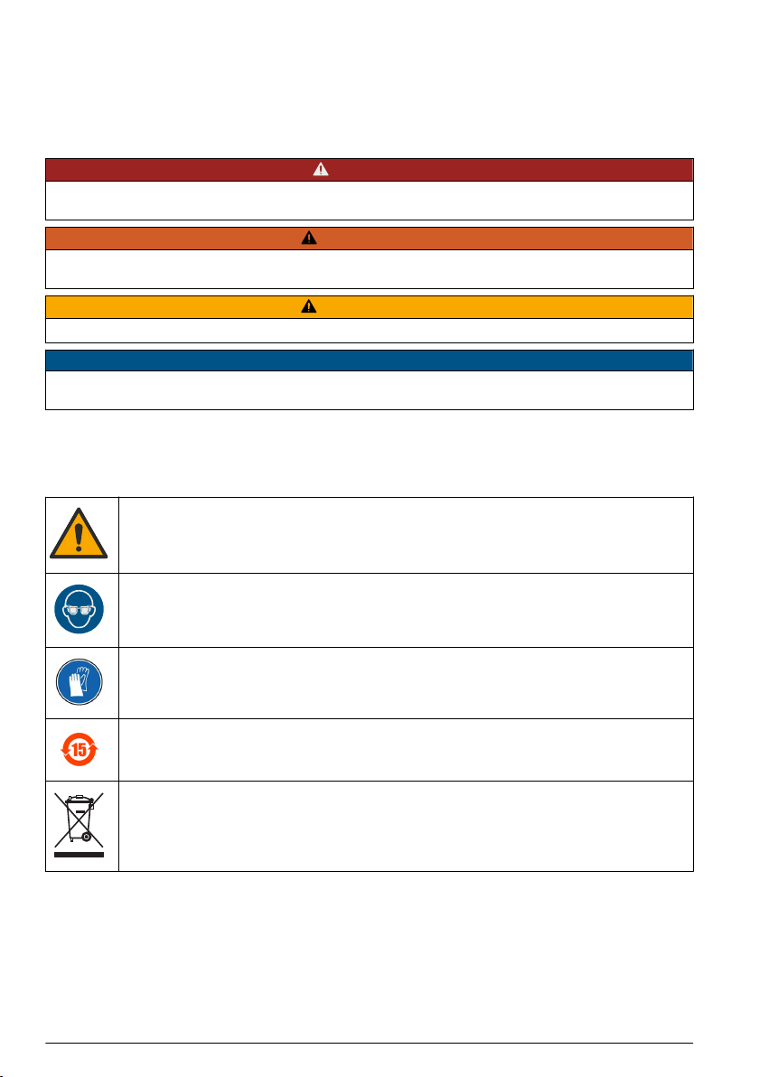
4.1.2 Precautionary labels
Read all labels and tags attached to the instrument. Personal injury or damage to the instrument
could occur if not observed. A symbol on the instrument is referenced in the manual with a
precautionary statement.
This is the safety alert symbol. Obey all safety messages that follow this symbol to avoid potential
injury. If on the instrument, refer to the instruction manual for operation or safety information.
This symbol indicates the need for protective eye wear.
This symbol indicates the need for protective hand wear.
Products marked with this symbol indicates that the product contains toxic or hazardous substances
or elements. The number inside the symbol indicates the environmental protection use period in
years.
Electrical equipment marked with this symbol may not be disposed of in European domestic or
public disposal systems. Return old or end-of-life equipment to the manufacturer for disposal at no
charge to the user.
4.2 Product components
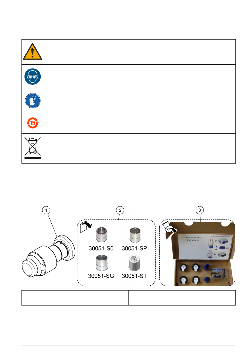
Make sure that all components have been received. Refer to Figure 1. If any items are missing or
damaged, contact the manufacturer or a sales representative immediately.
Figure 1 Product components
1 Sensor 3 Sensor recharge kit
2 Protection caps
4.2.1 Electrochemical sensor
The sensor may be delivered separately or as part of an ORBISPHERE system, depending on the
individual order.
The sensor will be delivered fitted with a plastic screw-on storage cap to protect the sensor head.
This is held in place with a plastic collar.
English
7
Page 8
A plastic screw-on base is also provided to protect the connection socket, and which also provides a
suitable stand for the sensor during maintenance procedures, and when not in use.
4.2.2 Protection caps
Non-ATEX sensors (GA2400)
Two protection caps will be delivered with each sensor, one without a grille (part number 33051-S0)
and one with a grille (part number 33051-SP).
A third protection cap (part number 33051-SG) is also available as an option and improves the
maintenance interval for beer or soft drinks process applications.
A fourth protection cap (part number 33051-ST) is delivered for the 6110 TPA application.
ATEX sensors (GA2800)
Only one protection cap will be delivered with each sensor (part number 33051-SG or 33051-H0).
4.2.3 Sensor recharge kit
A recharge kit should have been ordered with the sensor as this will be required to initially make the
sensor operational. It is also required for sensor cleaning and membrane replacement procedures.
Note: There are two different versions of the recharge kit. One version for GA2X00/A110X sensors and one version
for C1100 sensors. Refer to the documentation supplied with the kit for instructions on how to use the version of the
recharge kit with the applicable sensor.
The kit contains:
• four recharge cartridges with pre-mounted membrane and electrolyte. The type of membrane
mounted in the cartridge will be specific to the kit ordered
• two anode cleaning tools
• two sets of five cotton washers and five silicone discs (only for 2956A-XXX)
Note: The box for GA2X00 sensors has a blue label and the box for A110X sensors has a black label.
• one set of replacement O-rings and Dacron® mesh patches, applicable for GA2X00 and A110X
sensors
The blue anode cleaning tool is used to clean the anode of any deposits or residue that may have
formed. It is doubled-ended so it can be used for two membrane replacement processes, each end
being used once. Refer to the documentattion supplied with the recharge kit for instructions on how
to use the anode cleaning tool for a GA2X00 sensor or for a A110X sensor.
The cotton washers provide additional protection against the formation of deposits and residue on
the center electrode and anode, which prolongs the time period required between sensor
maintenance.
The silicone discs are required for measurements in ultra-pure water or water containing ammonia.
The Dacron® mesh patches provide protection to the membrane when using a protection cap with a
grille.
Section 5 Installation
Multiple hazards. Only qualified personnel must conduct the tasks described in this section of the
document.
5.1 Sensor preparation
Chemical exposure hazard. Obey laboratory safety procedures and wear all of the personal
protective equipment appropriate to the chemicals that are handled. Refer to the current safety data
sheets (MSDS/SDS) for safety protocols.
8 English
C A U T I O N
C A U T I O N
Page 9

Your sensor has been thoroughly cleaned and tested at the factory before shipment. It has been
shipped with a cartridge containing a membrane and electrolyte pre-installed to protect the sensor
head. This cartridge must be removed and replaced with a new one prior to first use to make it fully
operational. The new cartridge is included in the sensor recharge kit.
• Non-ATEX sensors (GA2400). The sensor has been delivered with two protection caps, one with
a grille and one without. Ensure you use the correct protection cap for your application. Refer to
Sensor configurations on page 3 for additional information.
• ATEX sensors (GA2800). The sensor has been delivered with a single protection cap.
The following instructions detail the steps required to make the sensor operational.
Note: It is advisable to perform this procedure with the plastic sensor base installed so as to avoid any damage to
the connection socket and also to provide a suitable stand for the sensor when required.
English 9
Page 10

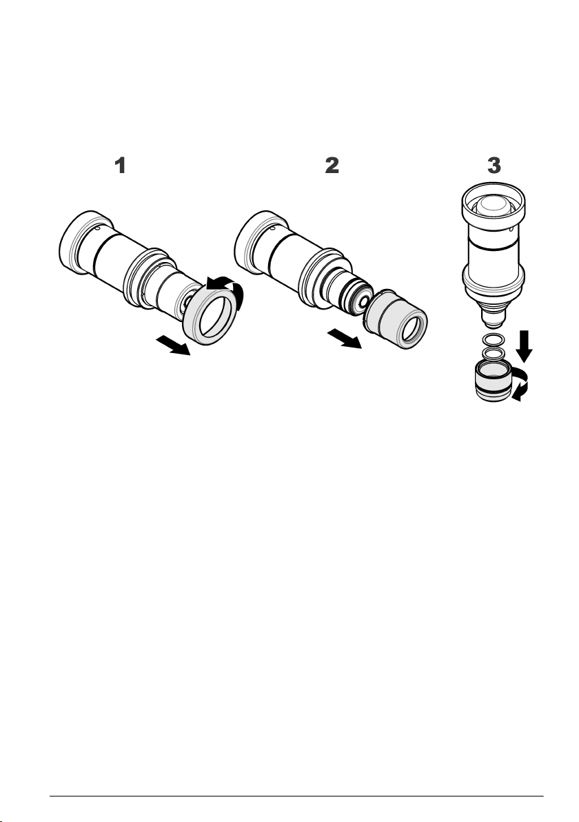
1. Hold the main body of the sensor and unscrew the protection cap locking washer by turning
counter-clockwise. Remove it from the sensor and put to one side.
2. Pull/twist off the protection cap and put to one side.
3. Hold the sensor with the membrane facing down to avoid spilling any electrolyte, then carefully
unscrew the shipment cartridge. Drain the old electrolyte into a sink and flush away. Discard the
shipment cartridge and membrane. Remove the cotton washer and silicone disc from the top of
the anode and discard.
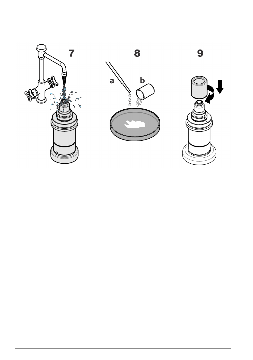
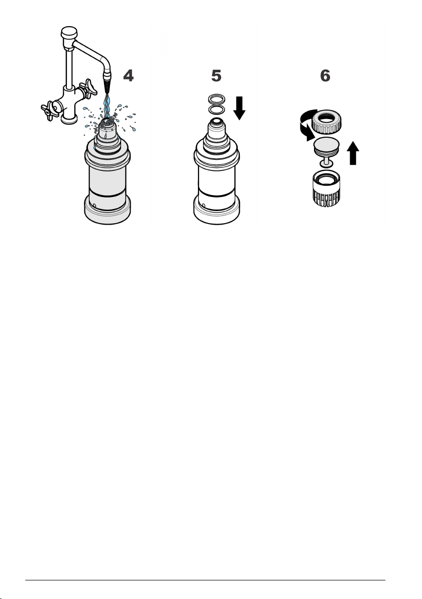
4. Rinse the sensor head under a tap for 15 seconds, aiming the jet of water directly onto the sensor
head. Do not dry the center electrode area, as the gap between cathode and guard should be left
filled with water.
5. Take a silicone disc from the recharge kit, hold it between thumb and forefinger and position it on
top of the anode. Take a new cotton washer from the recharge kit. Hold it between thumb and
forefinger and position it on top of the silicone disc.
Note: During this step, it is very important to ensure your finger does not come into contact with the cathode
(golden surface) as it could leave greasy deposits on the surface.
6. Place the recharge cartridge container on a flat work surface and, keeping the container upright
to avoid spilling any of the electrolyte inside, carefully unscrew the top. Remove the packing
component from the center of the cartridge, making sure that the O-ring on top of the cartridge
remains in place. If it comes away then replace it before continuing. If there are any visible
bubbles in the electrolyte, remove them using a stirring motion with the packing component.
Note: The recharge cartridge container will be colored black for all applications except for the 6110 TPA where
it will be colored white.
10
English
Page 11
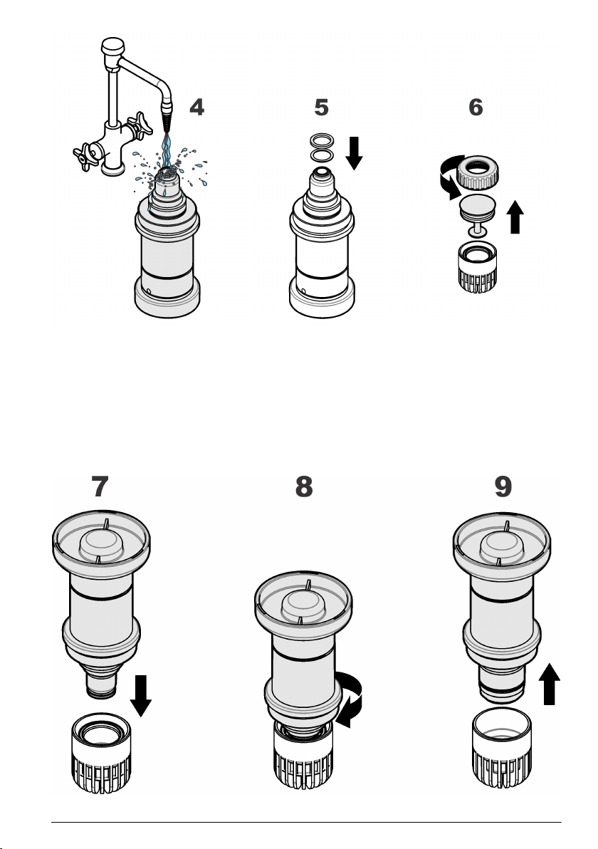
7. Hold the container steady between thumb and forefinger of one hand. Lower the sensor into the
container until the top of the anode is covered with electrolyte. Leave for a few seconds to ensure
the cotton washer has fully absorbed some of the electrolyte and that it is no longer dry.
8. Gently screw the sensor clockwise into the replacement cartridge, applying minimum pressure to
avoid any damage to the screw threads.
9. Continue turning until the cartridge is attached to the sensor, and the sensor is automatically
released from the container. The empty container, the screw top and packing component can be
discarded.
Note: It is normal that some of the electrolyte will overflow from the replacement cartridge and into the plastic
container.
English
11
Page 12
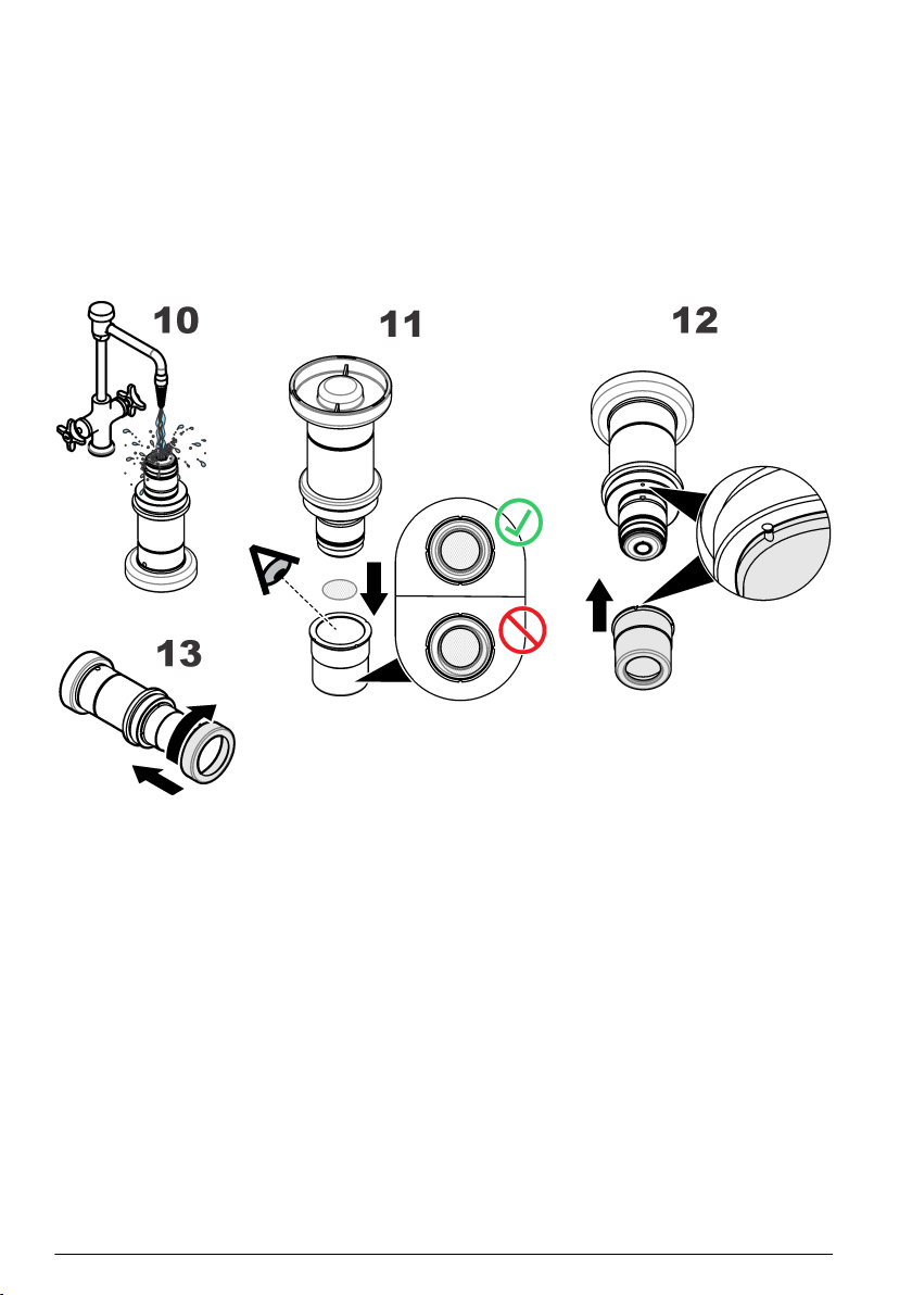
10. Rinse the sensor under a tap for about 5 seconds to remove any excess electrolyte, then gently
wipe with a soft tissue to ensure all parts are completely dry. Drain the overflow electrolyte from
the container into a sink and flush away. Discard the used container.
11. If not using a protection cap with grille proceed to step 12. Otherwise take a new Dacron® mesh
patch from the box of O-rings in the recharge kit. Place the mesh in the center of the protection
cap. It is very important that the mesh is in the center of the protection cap and covering the
entire grille. Lower the sensor onto the protection cap making sure not to disturb the mesh.
12. Push the protection cap firmly into place, making sure one of the four slots in the protection cap
fits over the small locking pin (highlighted right). If it is necessary to turn the protection cap to fit
over the locking pin, ensure you only turn it clockwise to avoid unscrewing the cartridge.
13. Finally, screw the protection cap locking washer back into place in a clockwise motion, and
tighten finger tight.
5.2 Sensor installation
5.2.1 Sensor positioning information
Unless the sensor is part of the ORBISPHERE equipment that includes it, the sensor must be
installed in an ORBISPHERE socket or flow chamber, that allows contact with the sample fluid to be
analyzed.
The sensor and measuring instrument are connected by a cable and two 10-pin connectors. The
standard sensor cable length is 3 meters though extension cables of up to 1000 meters are available.
However, smart sensor technology is only available with distances of up to a maximum of
750 meters.
Note: If the model 28117 pressure sensor is used, the maximum cable length is 50 meters.
Ensure that the sensor will be mounted:
• perpendicular to the pipe
• horizontal
• on a horizontal pipe section (or on flow-ascending vertical pipe)
• minimum of 15 meters away from the pump's discharge side
• in a place where the sample flow is stable and rapid, and as far as possible from:
12
English
Page 13
• valves
• pipe bends
• the suction side of any pumps
• a CO2 injection system or similar
Note: There may be situations where not all the above conditions can be met. If this is the case, or you have any
concerns, please consult your Hach representative to appraise the situation and define the best applicable solution.
5.2.2 Sensor insertion
Note: Check that the small O-ring at the bottom of the flow chamber is present during removal and installation of
the sensor, as it may stick to the sensor head and fall.
• Insert the sensor straight into the flow chamber or socket.
• Hand tighten the attaching collar.
• Connect the sensor cable.
• Check for leaks; replace O-rings if product leaks are visible.
Note: Do not twist the sensor when inserting it into a micro volume flow chamber. This rotation may twist the
membrane holding ring, thus changing the membrane position. This can modify the membrane measuring
conditions, and affect measurement precision.
5.2.3 Sensor removal
• Shut off the sample flow and drain the sampling circuit of liquid or gas.
• Remove the sensor cable connected at the sensor end.
• Hold the sensor body in one hand to avoid rotation and unscrew the collar with the other hand.
• Pull the sensor straight out of the socket or flow chamber.
• Check that both O-rings remain in place inside the flow chambers.
• Install the sensor storage cap and sensor base (to protect the connection).
Section 6 Maintenance
W A R NI N G
Multiple hazards. Only qualified personnel must conduct the tasks described in this section of the
document.
6.1 Maintenance schedule
The following table shows the recommended schedule for membrane replacement. The table should
only be used as a guideline, as maintenance intervals will vary depending on a number of different
parameters (e.g. water chemistry, CIP frequency, oxygen levels, sample temperature, etc.).
Application Membrane type Membrane replacement
Water applications (> 10 ppb) 2956A Every 3 to 6 months
Pure water applications (power and electronics < 10 ppb) 2956A Every 3 to 6 months
Beer in-line 2952A Every 3 to 6 months
Portable or lab applications 2952A or 2958A Every 3 to 6 months
Wort in-line 29552A or 2995A Every 1 or 2 months
6.2 Prerequisites for sensor maintenance
The following table lists the prerequisites for a sensor maintenance:
English
13
Page 14

Part No. Description
2959 Electrolyte for oxygen sensors, 50-mL bottle.
29781 Cathode polishing powder (part no.29331) and cloth (part no. 2934).
32301 Electrochemical cleaning and regeneration center (see below)
40089 Tweezers, for maintenance kits
DG33303 Cleaning tool for sensor polishing for A110X and C1100 sensors only
DG33629 Cleaning tool for sensor polishing for GA2X00 sensors only
DG33619 Regeneration Cell for GA2X00/A1100 or C1100 sensors
DG33620 Orbisphere EC sensor support for cleaning
Note: If the sensor is being used in a high level hydrogen sample, this cleaning and regeneration center is not
required. In all other cases it is a prerequisite.
The ORBISPHERE 32301 is a very efficient cleaning and regeneration tool for electrochemical
sensors. Refer to Figure 2. This tool reverses the electrochemical process that is taking place in the
sensor cell during normal operation. This removes oxidation and at the same time regenerates the
surface of the electrodes. In addition, the regeneration center offers a continuity tester for checking
the sensor electronics.
Figure 2 ORBISPHERE 32301 cleaning and regeneration tool
6.3 Membrane replacement and sensor head cleaning
C A U T I O N
Chemical exposure hazard. Obey laboratory safety procedures and wear all of the personal
protective equipment appropriate to the chemicals that are handled. Refer to the current safety data
sheets (MSDS/SDS) for safety protocols.
A sensor recharge kit is required as it contains all the components necessary for this membrane
replacement and sensor head cleaning process. Refer to Sensor recharge kit on page 8.
Note: It is advisable to perform this procedure with the plastic sensor base installed so as to avoid any damage to
the connection socket and also to provide a suitable stand for the sensor when required.
1. Hold the main body of the sensor and unscrew the protection cap locking washer by turning
counter-clockwise. Remove it from the sensor and put to one side.
2. Pull/twist off the protection cap and put to one side. If you are using a protection cap with a grille,
then remove the Dacron® mesh from inside the cap and discard it.
3. Hold the sensor with the membrane facing down to avoid spilling any electrolyte, then carefully
unscrew the old cartridge. Drain the old electrolyte into a sink and flush away. Discard the old
cartridge and membrane. Remove the cotton washer and silicone disc from the top of the anode
and discard.
14
English
Page 15
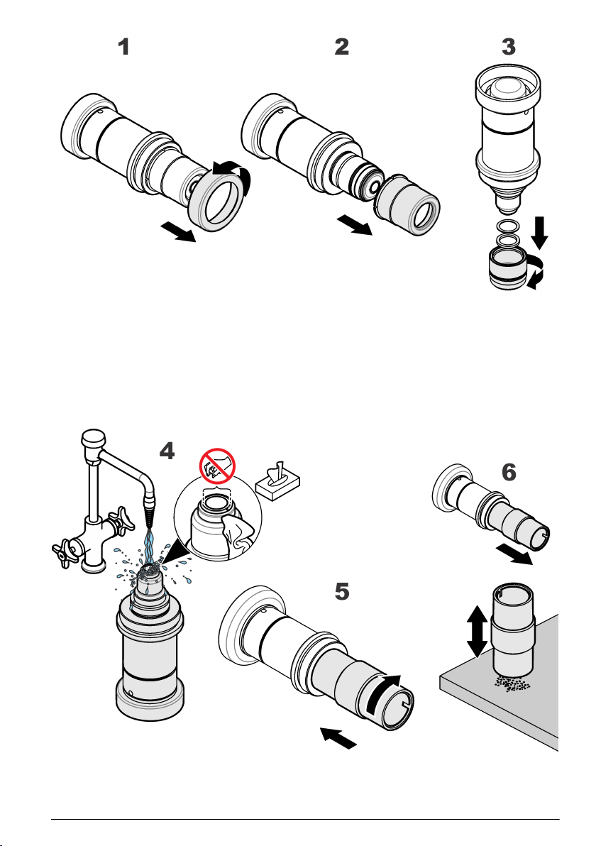
4. Rinse the sensor head under a tap for 15 seconds to remove any remaining electrolyte and shake
dry. With a soft tissue gently clean around the guard area (indicated right) and then wipe off any
excess moisture from the sensor to ensure all parts are completely dry. Repeat this rinse and dry
process with the protection cap.
5. Clean the anode using the cleaning tool supplied. Place the tool over the sensor head. Clean by
rotating the cleaning tool over the sensor head for a few seconds, in a clockwise direction only.
6. Remove the tool and tap it face down on a flat work surface to remove any powdery deposit.
Check the sensor to ensure that all deposits have been removed from the anode. If not, repeat
step 5. until the anode regains its bright silver appearance.
7. Rinse the sensor head under a tap for 15 seconds, aiming the jet of water directly onto the sensor
head. Do not dry the center electrode area, as the gap between cathode and guard should be left
filled with water.
English
15
Page 16
8. On the clean polishing cloth (2934) do the steps that follow:
a. Add a few drops of water.
b. Spread a little of the polishing powder (29331) to form a grey, milky liquid.
9. Screw the polishing tool (DG33629) onto the top of the sensor.
10. Polish the electrodes by moving the sensor face in a circular direction against the liquid in the
polishing cloth for about 30 seconds.
11. Remove the polishing tool from the sensor. Remove any polish deposits by rinsing the sensor
head under a tap for 30 seconds, aiming the jet of water directly onto the sensor head.
Note: If the sensor is used in high level hydrogen sample, do not perform the following steps but continue at
step 19.
12. Remove the plastic base from the bottom of the sensor and connect the sensor to the sensor
cleaning and regeneration center (32301).
16
English
Page 17
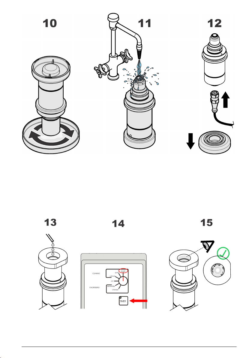
13. Push the cleaning tool over the sensor head. Pour enough electrolyte (2959) into the cleaning
tool until it completely covers all the electrodes.
Note: For DG33619 regeneration cell, screw the regeneration cell on the sensor head.
14. On the sensor cleaning and regeneration center, turn the knob to the Anode position and press
the TIMER switch. A red warning light will come on and remain on for 60 seconds while cleaning
takes place.
15. At the end of the 60 second cleaning process, check for an abundant stream of bubbles that
should rise from the anode. If this does not happen, press TIMER again.
Note: The development of bubbles is a sure sign of a clean electrode.
16. On the sensor cleaning and regeneration center, turn the knob to the Guard position and press
the TIMER switch. Again, watch for the formation of bubbles and repeat the cleaning process if
necessary.
English
17
Page 18
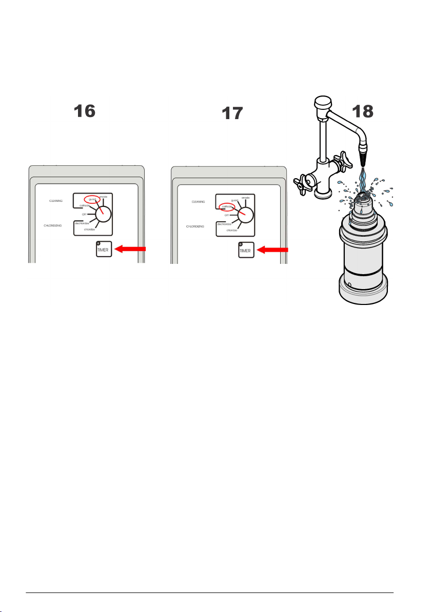
17. On the sensor cleaning and regeneration center, turn the knob to the Cathode position and press
the TIMER switch. Again, watch for the formation of bubbles and repeat the cleaning process if
necessary.
18. When cleaning is complete, unplug the sensor from the cleaning center and re-install the plastic
sensor base for the rest of the procedure. Remove any remaining electrolyte by rinsing the
sensor head under a tap for 60 seconds, aiming the jet of water directly onto the sensor head.
Note: For DG33619 regeneration cell, unscrew the regeneration cell from the sensor head.
19. With the help of a pair of tweezers, remove the old O-ring from the sensor body. Replace the O-
ring with a new one from the recharge kit.
20. Take a silicone disc from the recharge kit, hold it between thumb and forefinger and position it on
top of the anode. Take a new cotton washer from the recharge kit. Hold it between thumb and
forefinger and position it on top of the silicone disc.
Note: During this step, it is very important to ensure your finger does not come into contact with the cathode
(golden surface) as it could leave greasy deposits on the surface.
21. Place the recharge cartridge container on a flat work surface and, keeping the container upright
to avoid spilling any of the electrolyte inside, carefully unscrew the top. Remove the packing
component from the center of the cartridge, and make sure that the O-ring remains in place on
top of the cartridge. If it comes away then replace it before continuing. If there are any visible
bubbles in the electrolyte, remove them using a stirring motion with the packing component.
Note: The recharge cartridge container will be colored black for all applications except for the 6110 TPA where
it will be colored white.
18
English
Page 19
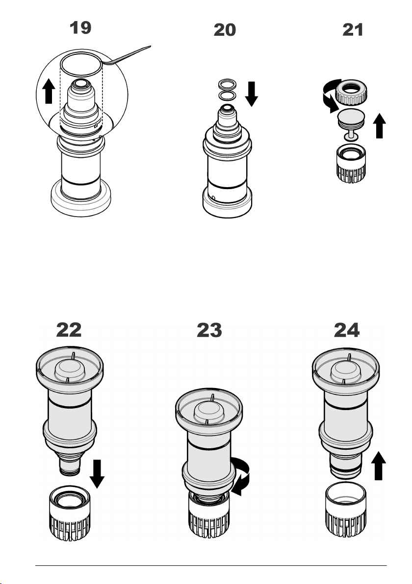
22. Hold the container steady between thumb and forefinger of one hand. Lower the sensor into the
container until the top of the anode is covered with electrolyte. Leave for a few seconds to ensure
the cotton washer has fully absorbed some of the electrolyte and that it is no longer dry.
23. Gently screw the sensor clockwise into the replacement cartridge, applying minimum pressure to
avoid any damage to the screw threads.
24. Continue turning until the cartridge is attached to the sensor, and the sensor is automatically
released from the container. The empty container, the screw top and packing component can be
discarded.
Note: It is normal that some of the electrolyte will overflow from the replacement cartridge and into the plastic
container.
English
19
Page 20
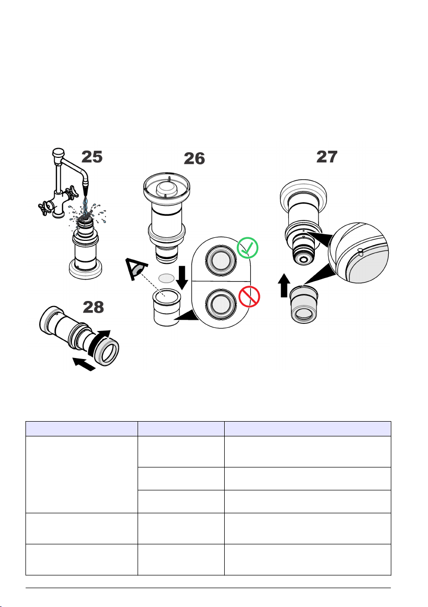
25. Rinse the sensor under a tap for about 5 seconds to remove any excess electrolyte, then gently
wipe with a soft tissue to ensure all parts are completely dry. Drain the overflow electrolyte from
the container into a sink and flush away. Discard the used container.
26. If not using a protection cap with grille proceed to step 27. Otherwise, take a new Dacron® mesh
patch from the box of O-rings in the recharge kit. Place the mesh in the center of the protection
cap. It is very important that the mesh is in the center of the protection cap and covering the
entire grille. Lower the sensor onto the protection cap making sure not to disturb the mesh.
27. Push the protection cap firmly into place, making sure one of the four slots in the protection cap
fits over the small locking pin (highlighted right). If it is necessary to turn the protection cap to fit
over the locking pin, ensure you only turn it clockwise to avoid unscrewing the cartridge.
28. Finally, screw the protection cap locking washer back into place in a clockwise motion, and
tighten finger tight.
Section 7 Troubleshooting
7.1 Oxygen sensor
Problem Probable cause Possible solution
Sensor won't calibrate, even after
cleaning and/or membrane
change.
"0000" O2 levels displayed. Wrong reading scale
Shorter than expected sensor
operation in relatively high
dissolved O2 concentration.
20 English
Instrument internal
barometric pressure
sensor needs calibration.
Wet membrane
interface.
"H2S insensitivity" option
enabled.
"XXXX" selected for
display unit.
High O2 concentrations
generate deposits more
quickly.
Calibrate using a certified barometer. Do not
correct for sea level !
Wipe dry with a tissue and re-calibrate.
Disable from the menu on the measuring
instrument.
Change reading scale by selecting "X.XXX, XX.XX
or XXX.X" on the instrument.
Install a less permeable membrane.
Turn off the analyzer when sensor is not in a low
O2 concentration.
Page 21

Problem Probable cause Possible solution
Unexpected or inaccurate
dissolved O2 readings.
Calibration is out of specification
or response time is too slow.
Air leak on product
sample line.
High residual current. Place sensor in de-aerated sample and wait for
Sensor incorrectly setup. Check the sensor parameters on the instrument.
Temperature
measurement incorrect.
Barometric pressure
incorrect.
Cartridge incorrectly
assembled on sensor.
Sensor electrodes are
dirty.
Sensor maintenance is
required.
Set flow rate to 100 mL/min. Wait until stable, then
slowly double the flow rate.
The stable value of dissolved O2 reading must be
the same as before. A variation related to flow rate
is a clear sign of an air leak in the line.
low reading.
Check concentration against low measurement
limit (refer to Sensor membrane specifications
on page 4).
If concentration is significantly higher than low
limit, try replacing the membrane.
Re-calibrate the sensor.
Control the temperature with an external
reference.
Re-calibrate the sensor.
Calibrate the barometric pressure sensor using
the instrument.
Re-calibrate the sensor.
Verify the cartridge assembly is firmly screwed
onto the sensor and that the membrane is tight.
Re-calibrate the sensor.
Clean the sensor using the ORBISPHERE
32301 cleaning and regeneration center as
explained in this section.
Re-calibrate the sensor.
Replace the membrane by installing a new sensor
cartridge as explained in this section.
Re-calibrate the sensor.
English 21
Page 22

Inhaltsverzeichnis
1 Inhaltsverzeichnis auf Seite 22
2 Spezifikationen auf Seite 22
3 Erweiterte Version des Handbuchs auf Seite 25
4 Allgemeine Informationen auf Seite 25
5 Installation auf Seite 28
6 Wartung auf Seite 33
7 Fehlerbehebung auf Seite 40
Kapitel 1 Inhaltsverzeichnis
Spezifikationen auf Seite 22 Wartung auf Seite 33
Allgemeine Informationen auf Seite 25 Fehlerbehebung auf Seite 40
Installation auf Seite 28
Kapitel 2 Spezifikationen
Die Spezifikationen können ohne Vorankündigung Änderungen unterliegen.
2.1 Sensorspezifikationen
Tabelle 1 ORBISPHERE GA2X00 Sauerstoffsensorfamilie
Spezifikation Informationen – Non-ATEX-
Typ Elektrochemischer Sauerstoffsensor
Abmessungen (Ø × L) 32 × 86,3 mm (1,26 × 3,40 Zoll)
Gewicht 300 g
Druckfestigkeit Max. 40 bar mit Defaultkragen aus PPS (100 bar mit Kragen aus Edelstahl)
Materialien Edelstahl Edelstahl oder Hastelloy
Sonstiges Smart-Kapazität Eigensicher
Zertifizierungen CE CE, Ex II 1 G, Ex ia IIC T6
Sensoren
Sensorkopf: Kalrez®-O-Ringe
Sensorboden: Viton® O-Ringe
1
Informationen – ATEX-Sensoren
EPDM- und Kalrez®-O-Ringe
Sensorkopf: Kalrez®-O-Ringe
Sensorboden: Viton® O-Ringe oder Kalrez®-ORinge
Hinweis: Im Unterschied zu den Non-ATEX-Sensoren GA2400 weisen die eigensicheren ATEX-Sensoren
GA2800 ATEX keine Smart-Kapazität zum Abspeichern von Kalibrierungsdaten auf. Bei allen ATEX-Sensoren
GA2800 sind die Informationen zur ATEX-Konformität in den Sensor selbst eingraviert
2.2 Sensorkonfigurationen
Tabelle 2 Getränk
Anwendung Sensor Membrankartusche Schutzkappe
Beer mit ORBISPHERE
3650 tragbar
Bier in der Leitung GA2400-S00 2952A-A 33051-SG
Bierwürze in der Leitung GA2400-S00 29552A-A 33051-S0
1
Viton und Kalrez sind Marken der DuPont Corporation.
22 Deutsch
GA2400-S00 2958A-A (optimierte
Reaktionszeit)
2952A-A (optimiertes
Wartungsintervall)
33051-SP
Page 23
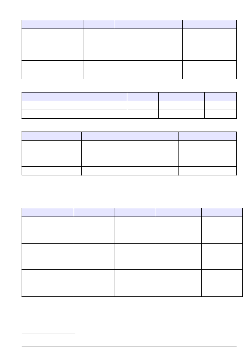
Tabelle 2 Getränk (fortgesetzt)
Anwendung Sensor Membrankartusche Schutzkappe
Bierwürze mit ORBISPHERE
3650 tragbar und spezieller
Flusszelle 32007W.xxx
ORBISPHERE 6110 PaketAnalysator (TPA)
Entlüftetes Wasser GA2400-S00 2956A-A oder 2952A-A 33051-S0
GA2400-S00 29552A-A 33051-S0
GA2400-S00T 2956A-A 33051-ST
33051-SG (falls der CIP
ausgesetzt ist)
Tabelle 3 Anwendungen mit reinem Wasser (Strom - Elektronik)
Anwendung Sensor Membrankartusche Schutzkappe
Online gelöste Sauerstoffspuren in reinem Wasser GA2400-S00 2956A-A 33051-S0
Gelöste Sauerstoffspuren mit 3655 tragbar GA2400-S00 2956A-A 33051-S0
Tabelle 4 ATEX
Sensor Membrankartusche Schutzkappe
GA2800-SVS 2956A-A oder 29552A-A 33051-SG
GA2800--SKS 2956A-A oder 29552A-A 33051-SG
GA2800--HVS 2956A-A oder 29552A-A 33051-H0
GA2800--HKS 2956A-A oder 29552A-A 33051-H0
2.3 Spezifikationen der Membran des Sensors
2.3.1 Sauerstoffsensoren (Tabelle 1)
Tabelle 5 Spezifikationen der Membran - Sauerstoffsensoren (1)
Spezifikation 2956A-A 2958A-A 29552A-A 2952A-A
Empfohlene
Anwendungen
Material PFA Tefzel®
Stärke [μm] 25 12,5 50 25
Kalibrierungsgas Luft Luft Luft Luft/reiner O
Messbereich gelöste
Gase
Messbereich gasförmige
Medien
Korrosionskontrolle,
Entlüftetes Wasser
0 ppb bis 20 ppm 0 ppb bis 40 ppm 0 ppb bis 80 ppm 0 ppb bis 80 ppm
0 Pa bis 50 kPa 0 Pa bis 100 kPa 0 Pa bis 200 kPa 0 Pa bis 200 kPa
Getränk,
Laboranwendungen
2
Bierwürze in der
Leitung,
Luft/O2-Einspritzung,
Abwasseraufbereitung
PTFE Tefzel
Korrosionskontrolle,
Getränk in der
Leitung,
Entlüftetes Wasser
®
2
2
Tefzel ist eine Marke der DuPont Corporation.
Deutsch 23
Page 24

Tabelle 5 Spezifikationen der Membran - Sauerstoffsensoren (1) (fortgesetzt)
Spezifikation 2956A-A 2958A-A 29552A-A 2952A-A
Genauigkeit Der größere Wert
von
± 1 % der Anzeige
oder ± 0.1 ppb3,
oder ±1 ppb4,
oder ± 0,25 Pa
Integrierter
2 x 10
4
Strahlungsdosisgrenzwert
[rads]
Erwarteter Strom in Luft
26,4 9,4 6,3 5,4
bei 1 bar 25 °C [µA]
Erwarteter Strom in
132 47 31,4 27
reinem O2 [µA]
O2-Verbrauch in O2-
40 14 9,4 8
gesättigtem Wasser bei
25 °C [µg/Stunde]
Temp.kompensationsbereich
Temp.- Messbereich – 5 bis 100 °C
Reaktionszeit
Empfohlene
5
7.2 Sek. 9.5 Sek. 90 Sek. 38 Sek.
180 120 50 50
Mindestdurchflussrate der
Flüssigkeit6 [mL/min]
Empfohlene lineare
Mindestdurchflussrate
6
200 100 30 30
[cm/Sek.]
Empfohlene
Durchflussrate des
gasförmigen Mediums
[L/min]
Der größere Wert
von
± 1 % der Anzeige
oder ±1 ppb,
oder ± 2 Pa
8
10
– 5 bis 60 °C
Der größere Wert von
± 1 % der Anzeige
oder ± 2 ppb,
oder ± 5 Pa
n. z. 10
0,1 bis 3
Der größere Wert
von
± 1 % der Anzeige
oder ± 2 ppb,
oder ± 5 Pa
8
2.3.2 Sauerstoffsensoren (Tabelle 2)
Tabelle 6 Spezifikationen der Membran - Sauerstoffsensoren (2)
Spezifikation 2935A-A 29521A-A 2995A-A
Empfohlene Anwendungen Gesättigte bis
übersättigte Pegel
Material Halar®
7
Stärke [μm] 25 125 12,5
Kalibrierungsgas Luft/reiner O
3
Die Genauigkeit beträgt ± 0,1 ppb für die Instrumente 410, 510, 362x, 360x und 3655.
4
Die Genauigkeit beträgt ± 1 ppb für die Instrumente 366x und 3650.
5
Reaktionszeit bei 25 °C für eine Signaländerung von 90 %
6
Durchfluss der Flüssigkeit durch eine Durchflusskammer ORBISPHERE 32001, mit
Schutzkappe und ohne Gitter
7
Halar ist eine Marke der Solvay Corporation.
2
24 Deutsch
Gesättigte bis
übersättigte Pegel
®
Tefzel
Luft/reiner O
2
Heiße Bierwürze in
der Leitung
(bis zu 70°C)
Tefzel
Reines O
®
2
Page 25
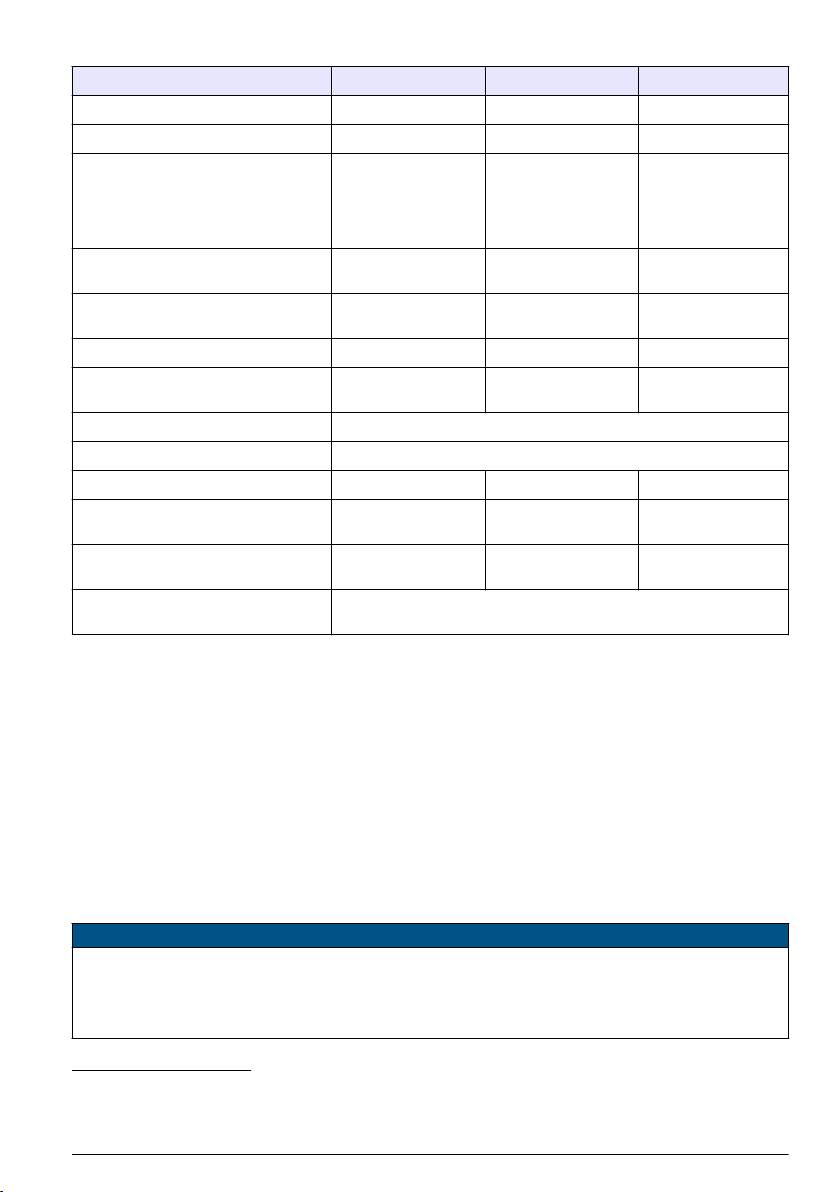
Tabelle 6 Spezifikationen der Membran - Sauerstoffsensoren (2) (fortgesetzt)
Spezifikation 2935A-A 29521A-A 2995A-A
Messbereich gelöste Gase 0 ppb bis 400 ppm 0 ppb bis 400 ppm 0 ppb bis 2.000 ppm
Messbereich gasförmige Medien 0 Pa bis 1000 kPa 0 Pa bis 1000 kPa 0 Pa bis 5.000 kPa
Genauigkeit Der größere Wert von
± 1 % der Anzeige
oder ± 10 ppb,
oder ± 20 Pa
Integrierter Strahlungsdosisgrenzwert
[rads]
Erwarteter Strom in Luft bei 1 bar 25 °C
[µA]
Erwarteter Strom in reinem O2 [µA] 4,7 3,8 0,9
O2-Verbrauch in O2-gesättigtem
Wasser bei 25 °C [µg/Stunde]
Temp.- kompensationsbereich – 5 bis 60 °C
Temp.- Messbereich – 5 bis 100 °C
Reaktionszeit
Empfohlene Mindestdurchflussrate der
Flüssigkeit9 [mL/min]
Empfohlene lineare
Mindestdurchflussrate9 [cm/Sek.]
Empfohlene Durchflussrate des
gasförmigen Mediums [L/min]
8
n. z. 10
0,9 0,7 0,2
1,4 1,3 0,3
2,5 min. 18 min. 80 Sek.
25 25 5
20 60 5
Der größere Wert von
± 1 % der Anzeige
oder ± 10 ppb,
oder ± 20 Pa
8
0,1 bis 3
Der größere Wert von
± 1 % der Anzeige
oder ± 50 ppb,
oder ± 100 Pa
8
10
Kapitel 3 Erweiterte Version des Handbuchs
Zusätzliche Informationen finden Sie in der ausführlichen Version dieser Bedienungsanleitung auf
der Website des Herstellers.
Kapitel 4 Allgemeine Informationen
Der Hersteller ist nicht verantwortlich für direkte, indirekte, versehentliche oder Folgeschäden, die
aus Fehlern oder Unterlassungen in diesem Handbuch entstanden. Der Hersteller behält sich
jederzeit und ohne vorherige Ankündigung oder Verpflichtung das Recht auf Verbesserungen an
diesem Handbuch und den hierin beschriebenen Produkten vor. Überarbeitete Ausgaben der
Bedienungsanleitung sind auf der Hersteller-Webseite erhältlich.
4.1 Sicherheitshinweise
H I N WE I S
Der Hersteller ist nicht für Schäden verantwortlich, die durch Fehlanwendung oder Missbrauch dieses Produkts
entstehen, einschließlich, aber ohne Beschränkung auf direkte, zufällige oder Folgeschäden, und lehnt jegliche
Haftung im gesetzlich zulässigen Umfang ab. Der Benutzer ist selbst dafür verantwortlich, schwerwiegende
Anwendungsrisiken zu erkennen und erforderliche Maßnahmen durchzuführen, um die Prozesse im Fall von
möglichen Gerätefehlern zu schützen.
8
Reaktionszeit bei 25 °C für eine Signaländerung von 90 %
9
Durchfluss der Flüssigkeit durch eine Durchflusskammer ORBISPHERE 32001, mit
Schutzkappe und ohne Gitter
Deutsch 25
Page 26
Bitte lesen Sie dieses Handbuch komplett durch, bevor Sie dieses Gerät auspacken, aufstellen oder
bedienen. Beachten Sie alle Gefahren- und Warnhinweise. Nichtbeachtung kann zu schweren
Verletzungen des Bedieners oder Schäden am Gerät führen.
Stellen Sie sicher, dass die durch dieses Messgerät bereitgestellte Sicherheit nicht beeinträchtigt
wird. Verwenden bzw. installieren Sie das Messsystem nur wie in diesem Handbuch beschrieben.
4.1.1 Bedeutung von Gefahrenhinweisen
G E F AH R
Kennzeichnet eine mögliche oder drohende Gefahrensituation, die, wenn sie nicht vermieden wird, zum Tod oder
zu schweren Verletzungen führt.
Kennzeichnet eine mögliche oder drohende Gefahrensituation, die, wenn sie nicht vermieden wird, zum Tod oder
zu schweren Verletzungen führen kann.
Kennzeichnet eine mögliche Gefahrensituation, die zu leichteren Verletzungen führen kann.
Kennzeichnet eine Situation, die, wenn sie nicht vermieden wird, das Gerät beschädigen kann. Informationen, die
besonders beachtet werden müssen.
W A R NU N G
V O R SI C H T
H I N WE I S
4.1.2 Warnaufkleber
Lesen Sie alle am Gerät angebrachten Aufkleber und Hinweise. Nichtbeachtung kann Verletzungen
oder Beschädigungen des Geräts zur Folge haben. Im Handbuch wird in Form von Warnhinweisen
auf die am Gerät angebrachten Symbole verwiesen.
Dies ist das Sicherheits-Warnsymbol. Befolgen Sie alle Sicherheitshinweise im Zusammenhang mit
diesem Symbol, um Verletzungen zu vermeiden. Wenn es am Gerät angebracht ist, beachten Sie
die Betriebs- oder Sicherheitsinformationen im Handbuch.
Dieses Symbol kennzeichnet den Bedarf für einen Augenschutz.
Dieses Symbol weist darauf hin, dass Schutzhandschuhe getragen werden müssen.
Produkte, die mit diesem Symbol gekennzeichnet sind, enthalten toxische oder gefährliche
Substanzen oder Elemente. Die Ziffer in diesem Symbol gibt den Umweltschutzzeitraum in Jahren
an.
Elektrogeräte, die mit diesem Symbol gekennzeichnet sind, dürfen nicht im normalen öffentlichen
Abfallsystem entsorgt werden. Senden Sie Altgeräte an den Hersteller zurück. Dieser entsorgt die
Geräte ohne Kosten für den Benutzer.
4.2 Produktkomponenten
Stellen Sie sicher, dass Sie alle Teile erhalten haben. Siehe Abbildung 1. Wenn Elemente fehlen
oder beschädigt sind, kontaktieren Sie sofort den Hersteller oder die zuständige Vertretung.
26
Deutsch
Page 27

Abbildung 1 Produktkomponenten
1 Sensor 3 Sensornachfüllkit
2 Schutzkappen
4.2.1 Elektrochemischer Sensor
In Abhängigkeit von der Bestellung kann der Sensor separat oder als Teil eines ORBISPHERESystems geliefert werden.
Der Sensor wird mit einer aufgeschraubten Lagerungskappe aus Kunststoff zum Schutz des
Sensorkopfes geliefert. Dieser wird mit einem Plastikring in Position gehalten.
Außerdem ist ein aufgeschraubter Sockel aus Kunststoff zum Schutz der Anschlussbuchse
vorhanden, der dem Sensor während der Wartung und Nichtbenutzung auch einen festen Stand gibt.
4.2.2 Schutzkappen
Non-ATEX-Sensoren (GA2400)
Mit jedem Sensoren werden zwei Schutzkappen geliefert, eine ohne Gitter (Bauteilnummer 33051S0) und eine mit Gitter (Bauteilnummer 33051-SP).
Ein dritte Schutzkappe (Bauteilnummer 33051-SG) ist als Option lieferbar und verlängert das
Wartungsintervall für Anwendungen in Bier- und Softdrink-Prozessen.
Ein vierte Schutzkappe (Bauteilnummer 33051-ST) wird für die 6110 TPA Verwendung versendet.
ATEX-Sensoren (GA2800)
Mit jedem Sensor wird nur eine Schutzkappe geliefert (Bauteilnummer 33051-SG oder 33051-H0).
4.2.3 Sensornachfüllkit
Ein Nachfüllkit sollte mit dem Sensor bestellt werden, da er erforderlich ist, um den Sensor
einsatzbereit zu machen. Er ist ebenfalls für die Reinigung des Sensors und den Austausch der
Membran erforderlich.
Hinweis: Es gibt zwei verschiedene Versionen des Ersatzteilkits. Eine Version für die Sensoren
GA2X00 undA110X und eine Version für den Sensor C1100. Informationen zur Verwendung des Ersatzteilkits mit
dem entsprechenden Sensor finden Sie in der mitgelieferten Dokumentation.
Das Kit enthält:
• vier Nachfüllkartuschen mit vormontierter Membran und Elektrolyt. Der in der Kartusche montierte
Membrantyp ist von der Angabe bei der Bestellung abhängig.
• zwei Anodenreinigungswerkzeuge
• zwei Sätze mit je fünf Wolldichtungen und fünf Silikonscheiben (nur für 2956A-XXX)
Hinweis: Die Schachtel für GA2X00 Sensoren hat ein blaues und die Schachtel für A110X Sensoren ein
schwarzes Etikett.
• ein Satz Ersatz-O-Ringe und Maschenstücke aus Dacron®, geeignet für GA2X00 und A110X
Sensoren
Deutsch
27
Page 28

Das blaue Anodenreinigungswerkzeug wird für die Reinigung der Anode von Ablagerungen und
Rückständen verwendet, die sich gebildet haben können. Es weist zwei Enden für den Austausch
der Membran auf, die beide einmal benutzt werden können. Informationen zur Verwendung des
Anodenreinigungswerkzeugs für GA2X00 bzw. A110X Sensoren finden Sie in der mit dem
Ersatzteilkit mitgelieferten Dokumentation.
Die Wolldichtungen bieten einen zusätzlichen Schutz gegen die Bildung von Ablagerungen und
Rückstände auf der zentralen Elektrode und der Anode, wodurch das Wartungsintervall verlängert
wird.
Die Silikonscheiben sind für Messungen in ultrareinem Wasser oder in Wasser erforderlich, das
Ammoniak enthält.
Das Dacron®-Netz bietet einen Schutz der Membran bei der Verwendung von Schutzkappen mit
Gitter.
Kapitel 5 Installation
V O R SI C H T
Mehrere Gefahren. Nur qualifiziertes Personal sollte die in diesem Kapitel des Dokuments
beschriebenen Aufgaben durchführen.
5.1 Vorbereitung des Sensors V O R SI C H T
Gefahr von Kontakt mit Chemikalien. Halten Sie sich an die Sicherheitsmaßnahmen im Labor, und
tragen Sie Schutzkleidung entsprechend den Chemikalien, mit denen Sie arbeiten. Beachten Sie die
Sicherheitsprotokolle in den aktuellen Materialsicherheitsdatenblättern (MSDS/SDB).
Ihr Sensor wurde vor der Lieferung im Werk einer gründlichen Reinigung und Überprüfung
unterzogen. Er wurde mit einer Kartusche ausgeliefert, die eine vorinstallierte Membran und
Elektrolytflüssigkeit zum Schutz des Sensorkopfes enthält. Die Kartusche muss vor der ersten
Benutzung entfernt und durch eine neue ersetzt werden, um den Sensor einsatzbereit zu machen.
Die Kartusche ist im Sensornachfüllkit enthalten.
• NON-ATEX-Sensoren (GA2400). Der Sensor wurde mit zwei Schutzkappen geliefert, eine mit
Gitter und eine ohne. Stellen Sie sicher, dass Sie die richtige Schutzkappe für Ihre Anwendung
benutzen. Weitere Informationen finden Sie unter Sensorkonfigurationen auf Seite 22.
• ATEX-Sensoren (GA2800). Der Sensor wurde mit einer einzigen Schutzkappe geliefert.
Die folgenden Anweisungen geben die Schritte detailliert an, die erforderlich sind, um den Sensor
einsatzbereit zu machen.
Hinweis: Es ist ratsam, diesen Vorgang mit installiertem Sensorsockel aus Kunststoff auszuführen, um
Beschädigungen der Verbindungsbuchse zu vermeiden und weil er dem Sensor, falls erforderlich, den notwendigen
Stand bietet.
28
Deutsch
Page 29
1. Halten Sie den Hauptkörper des Sensors und schrauben Sie den Sperrring der Schutzkappe in
Gegenuhrzeigersinn ab. Entfernen Sie ihn vom Sensor und legen Sie ihn zur Seite.
2. Ziehen/drehen Sie die Schutzkappe ab und legen Sie sie zur Seite.
3. Halten Sie den Sensor mit der Membran nach unten, um ein Überlaufen von Elektrolytflüssigkeit
zu vermeiden, und schrauben Sie dann vorsichtig die Versandkartusche ab. Kippen Sie die alte
Elektrolytflüssigkeit in einen Abfluss und spülen Sie sie weg. Werfen Sie die Versandkartusche
und die Membran weg. Entfernen Sie die Wolldichtung und die Silikonscheibe von der Spitze der
Anode und werfen Sie sie weg.
4. Spülen Sie den Sensorkopf 15 Sekunden unter fließendem Wasser aus und richten Sie dabei
den Wasserstrahl direkt auf den Sensorkopf. Trocknen Sie den zentralen Bereich der Elektrode
nicht ab, da der Zwischenraum zwischen der Kathode und dem Schutz mit Wasser gefüllt bleiben
soll.
5. Nehmen Sie eine Silikonscheibe aus dem Ersatzteilkit, halten Sie sie zwischen Daumen und
Zeigefinger und setzen Sie auf die Anodenspitze auf. Nehmen Sie eine neue Wolldichtung aus
dem Ersatzteilkit. Halten Sie sie zwischen Daumen und Zeigefinger und setzen Sie sie auf die
Silikonscheibe auf.
Hinweis: Bei diesem Schritt ist es sehr wichtig, sicherzustellen, dass ihre Finger nicht mit der Kathode in
Kontakt geraten (goldene Oberfläche), da sonst Fettspuren auf der Oberfläche zurückbleiben könnten.
6. Stellen Sie den Behälter der Nachfüllkartusche auf eine ebene Arbeitsfläche, halten Sie den
Behälter aufrecht, um das Auslaufen der enthaltenen Elektrolytflüssigkeit zu verhindern, und
schrauben Sie die Oberseite vorsichtig ab. Entfernen Sie die Verpackung von der
Kartuschenmitte und stellen Sie sicher, dass der O-Ring auf der Oberseite der Kartusche
eingesetzt bleibt. Ersetzen Sie ihn, bevor Sie fortfahren, falls er verlorengeht. Entfernen Sie
eventuell sichtbare Blasen in der Elektrolytflüssigkeit durch eine Schüttelbewegung mit der
Verpackungskomponente.
Hinweis: Der Behälter der Nachfüllkartusche wird für alle Anwendungen schwarz gefärbt. Ausnahme ist die
6110 TPA, in diesem Fall ist er weiß gefärbt.
Deutsch
29
Page 30
7. Halten Sie den Behälter fest zwischen Daumen und Zeigefinger einer Hand. Senken Sie den
Sensor in den Behälter ab, bis die Oberseite der Anode mit Elektrolytflüssigkeit abgedeckt ist.
Lassen Sie ihn für einige Sekunden darin, um sicherzustellen, dass die Wolldichtung vollständig
mit Elektrolytflüssigkeit durchtränkt und nicht mehr trocken ist.
8. Schrauben Sie den Sensor vorsichtig im Uhrzeigersinn in die Ersatzkartusche und wenden Sie
dabei möglichst wenig Druck an, um eine Beschädigung des Gewindes zu vermeiden.
9. Drehen Sie weiter, bis die Kartusche am Sensor angebracht ist und der Sensor automatisch aus
dem Behälter freigegeben wird. Der leere Behälter, die Schraubenoberseite und die
Verpackungskomponente können entsorgt werden.
Hinweis: Es ist normal, dass ein wenig Elektrolytflüssigkeit aus der Ersatzkartusche in den Kunststoffbehälter
überläuft.
30
Deutsch
Page 31

10. Spülen Sie den Sensor ca. 5 Sekunden unter fließendem Wasser ab, um Rückstände von
Elektrolytflüssigkeit zu entfernen, und wischen Sie dann alle Bauteile mit einem weichen Tuch
trocken. Lassen Sie überlaufende Elektrolytflüssigkeit in einen Abfluss ablaufen und spülen Sie
sie weg. Werfen Sie den benutzten Behälter weg.
11. Wenn Sie keine Schutzkappe mit Gitter verwenden, fahren Sie mit Schritt 12 fort. Andernfalls
nehmen Sie ein neues Maschenstück aus Dacron® aus der O-Ring Schachtel im Ersatzteilkit.
Setzen Sie die Masche mittig in der Schutzkappe ein. Es ist sehr wichtig, dass sich die Masche
im Zentrum der Schutzkappe befindet und das Gitter vollständig abdeckt. Senken Sie den Sensor
auf die Schutzkappe ab und stellen Sie sicher, dass die Masche nicht gestört wird.
12. Drücken Sie die Schutzkappe fest in den Sitz und stellen Sie sicher, dass die vier Schlitze der
Schutzkappe in die kleinen Sperrklinken (rechts gezeigt) eintreten. Falls die Schutzkappe gedreht
werden muss, damit sie in die Sperrklinken eintritt, müssen Sie darauf achten, dass nur im
Uhrzeigersinn gedreht wird, um das Abschrauben der Kartusche zu vermeiden.
13. Schrauben Sie zum Abschluss den Sperrring der Schutzkappe wieder im Uhrzeigersinn auf und
ziehen Sie ihn mit den Fingern fest.
Deutsch
31
Page 32

5.2 Sensorinstallation
5.2.1 Informationen zur Sensorpositionierung
Information zur Positionierung Falls er nicht Teil einer Orbisphere- Ausrüstung ist, die ihn umfasst,
muss der Sensor auf einem Orbisphere-Sockel oder einer Flusskammer installiert werden muss, die
den Kontakt mit dem zu analysierenden Probenfluss gestatten.
Der Sensor und das Messinstrument sind über ein Kabel und zwei Steckverbinder mit
10 Kontaktstiften miteinander verbunden. Die Standardlänge des Sensorkabels beträgt 3 m, es sind
jedoch Verlängerungskabel mit Längen von bis zu 1.000 m verfügbar. Die Smart-SensorTechnologie ist jedoch nur für Entfernungen von bis zu maximal 750 m geeignet.
Hinweis: Falls der Drucksensor Modell 28117 verwendet wird, beträgt die max. Kabellänge 50 m.
Stellen Sie sicher, dass der Sensor wie folgt montiert wird:
• senkrecht zum Rohr
• horizontal
• in einem horizontalen Abschnitt des Rohrs (oder an einem vertikalen Rohr mit aufsteigendem
Durchfluss)
• mindestens 15 Meter von der Auslassseite der Pumpe entfernt
• an einer Stelle, an der der Durchfluss stabil und schnell ist, und so weit wie möglich entfernt von:
• Ventilen
• Rohrbögen
• den Ansaugseiten von Pumpen
• einem CO2-Einspritzsystem oder ähnlichen Vorrichtungen
Hinweis: In einigen Situation könnte es nicht möglich sein, alle vorgenannten Bedingungen zu erfüllen. Bitte
wenden Sie sich in diesem Fall an Ihren Hach-Vertreter, um die Situation zu bewerten und die beste anwendbare
Lösung zu finden.
32
Deutsch
Page 33

5.2.2 Einsetzen des Sensors
Hinweis: Stellen Sie sicher, dass der kleine O-Ring am Boden der Flusskammer beim Entfernen und beim
Einsetzen des Sensors vorhanden ist, da er am Sensorkopf kleben und herabfallen könnte.
• Setzen Sie den Sensor gerade in die Flusskammer oder den Sockel ein.
• Ziehen Sie die Spannmanschette von Hand fest.
• Schließen Sie das Sensorkabel an.
• Nehmen Sie eine Kontrolle auf Undichtigkeiten vor; ersetzen Sie die O-Ringe, falls Undichtigkeiten
sichtbar sind.
Hinweis: Drehen Sie den Sensor während des Einsetzens in eine Mikrovolumen-Flusskammer nicht. Durch diese
Rotation könnten der Halterungsring der Membran verdreht und die Position der Membran verändert werden.
Dadurch können die Messbedingungen der Membran verändert und die Messgenauigkeit beeinträchtigt werden.
5.2.3 Entfernung des Sensors
• Unterbrechen Sie den Fluss und lassen Sie die Flüssigkeit oder das Gas aus der Probenleitung
ab.
• Entfernen Sie das am Sensorende angeschlossene Sensorkabel.
• Halten Sie den Körper des Sensors in einer Hand, um Rotationen zu vermeiden, und schrauben
Sie mit der anderen Hand die Manschette ab.
• Ziehen Sie den Sensor gerade aus der Flusskammer oder dem Sockel.
• Stellen Sie sicher, dass die beiden O-Ringe in der Flusskammer verbleiben.
• Bringen Sie (zum Schutz des Anschlusses) Kappe für die Lagerung des Sensors und die Basis
des Sensors an.
Kapitel 6 Wartung
W A R NU N G
Mehrere Gefahren. Nur qualifiziertes Personal sollte die in diesem Kapitel des Dokuments
beschriebenen Aufgaben durchführen.
6.1 Wartungsplan
Die folgende Tabelle gibt den empfohlenen Plan für die Ersetzung der Membran. Die Tabelle sollte
als Richtlinie verwendet werden, da die Wartungsintervalle stark von einer Reihe verschiedener
Parameter abhängen (z. B. Wasserchemie, CIP-Frequenz, Sauerstoffpegel, Probentemperatur
usw.).
Anwendung Membrantyp Membran austauschen
Wasseranwendungen (> 10 ppb) 2956A Alle 3 bis 6 Monate
Reinwasseranwendungen (Strom und Elektronik < 10 ppb) 2956A Alle 3 bis 6 Monate
Bier in der Leitung 2952A Alle 3 bis 6 Monate
Portable Anwendungen oder Laboranwendungen 2952A oder 2958A Alle 3 bis 6 Monate
Bierwürze in der Leitung 29552A oder 2995A Alle 1 oder 2 Monate
6.2 Grundvoraussetzungen zur Wartung des Sensors
Die nachfolgende Tabelle führt die Grundvoraussetzungen zur Wartung des Sensors auf:
Bauteil Nr. Beschreibung
2959 Elektrolyt für Sauerstoffsensor, Flasche mit 50 mL.
29781 Kathoden-Polierpuder (Teilenr. 29331) und Tuch (Teilenr. 2934).
Deutsch 33
Page 34

Bauteil Nr. Beschreibung
32301 Elektrochemische Reinigungs- und Regenerierungseinheit (siehe unten)
40089 Pinzette, für Wartungskit
DG33303 Reinigungswerkzeug zum Polieren des Sensors nur für die Sensoren A110X und C1100
DG33629 Reinigungswerkzeug zum Polieren des Sensors nur für GA2X00 Sensoren
DG33619 Regenerierungszelle für GA2X00/A1100 oder C1100 Sensoren
DG33620 Orbisphere EC Sensorstütze für die Reinigung
Hinweis: Wird der Sensor in "High Level" Wasserstoffproben verwendet, ist die Reinigungs- und
Regenerierungseinheit nicht erforderlich. In allen anderen Fällen ist sie eine Grundvoraussetzung.
Das ORBISPHERE 32301 ist ein sehr effizientes Reinigungs- und Regenerierungswerkzeug für
elektrochemische Sensoren. Siehe Abbildung 2. Diese Vorrichtung kehrt den elektrochemischen
Prozess um, der während des normalen Betriebs in der Sensorzelle stattfindet. Dadurch werden
Oxidationen entfernt und gleichzeitig die Oberfläche der Elektroden regeneriert. Zusätzlich ist die
Regenerierungseinheit ein Testgerät für die Kontinuität zur Überprüfung der Elektronik des Sensors.
Abbildung 2 ORBISPHERE 32301 Reinigungs- und Regenerierungswerkzeug
6.3 Austausch der Membran und Reinigung des Sensorkopfes V O R SI C H T
Gefahr von Kontakt mit Chemikalien. Halten Sie sich an die Sicherheitsmaßnahmen im Labor, und
tragen Sie Schutzkleidung entsprechend den Chemikalien, mit denen Sie arbeiten. Beachten Sie die
Sicherheitsprotokolle in den aktuellen Materialsicherheitsdatenblättern (MSDS/SDB).
Ein Sensornachfüllkit ist erforderlich, da es alle Komponenten enthält, die für den Austausch der
Membran und die Reinigung des Sensorkopfes erforderlich sind. Siehe Sensornachfüllkit
auf Seite 27.
Hinweis: Es ist ratsam, diesen Vorgang mit installiertem Sensorsockel aus Kunststoff auszuführen, um
Beschädigungen der Verbindungsbuchse zu vermeiden und weil er dem Sensor, falls erforderlich, den notwendigen
Stand bietet.
1. Halten Sie den Hauptkörper des Sensors und schrauben Sie den Sperrring der Schutzkappe in
Gegenuhrzeigersinn ab. Entfernen Sie ihn vom Sensor und legen Sie ihn zur Seite.
2. Ziehen/drehen Sie die Schutzkappe ab und legen Sie sie zur Seite. Entfernen Sie die Dacron®-
Masche aus der Innenseite der Kappe und werfen Sie sie weg, falls Sie eine Schutzkappe mit
Gitter verwenden.
3. Halten Sie den Sensor mit der Membran nach unten, um ein Überlaufen von Elektrolytflüssigkeit
zu vermeiden, und schrauben Sie dann vorsichtig die alte Kartusche ab. Kippen Sie die alte
Elektrolytflüssigkeit in einen Abfluss und spülen Sie sie weg. Werfen Sie die alte Kartusche und
die Membran weg. Entfernen Sie die Wolldichtung und die Silikonscheibe von der Spitze der
Anode und werfen Sie sie weg.
34
Deutsch
Page 35

4. Spülen Sie den Sensorkopf 15 Sekunden unter fließendem Wasser aus, um alle Rückstände von
Elektrolytflüssigkeit zu entfernen, und trocknen Sie ihn dann ab. Wischen Sie mit einem sauberen
Tuch vorsichtig um den Schutzbereich (rechts gezeigt) und wischen Sie dann alle Rückstände
von Feuchtigkeit vom Sensor, um sicherzustellen, dass er vollkommen trocken ist. Wiederholen
Sie den Spül- und Trocknungsvorgang mit der Schutzkappe.
5. Reinigen Sie die Anode mit dem mitgelieferten Reinigungswerkzeug. Setzen Sie das Werkzeug
auf den Sensorkopf. Nehmen Sie die Reinigung vor, indem Sie das Reinigungswerkzeug einige
Sekunden auf dem Sensorkopf drehen, nur im Uhrzeigersinn.
6. Entfernen Sie das Werkzeug und setzen Sie es umgedreht auf eine flache Arbeitsfläche, um alle
Staubablagerungen zu entfernen. Überprüfen Sie den Sensor, um sicherzustellen, dass alle
Ablagerungen von der Anode entfernt wurden. Wiederholen Sie anderenfalls Schritt 5, bis die
Anode wieder silbern glänzt.
Deutsch
35
Page 36

7. Spülen Sie den Sensorkopf 15 Sekunden unter fließendem Wasser aus und richten Sie dabei
den Wasserstrahl direkt auf den Sensorkopf. Trocknen Sie den zentralen Bereich der Elektrode
nicht ab, da der Zwischenraum zwischen der Kathode und dem Schutz mit Wasser gefüllt bleiben
soll.
8. Führen Sie mit dem Poliertuch (2934) die folgenden Schritte durch:
a. Geben Sie einige Tropfen Wasser hinzu.
b. Verteilen Sie ein wenig Polierpuder (29331), bis Sie eine milchig-graue Flüssigkeit erhalten.
9. Schrauben Sie das Polierwerkzeug (DG33629) auf der Spitze des Sensors auf.
10. Polieren Sie die Elektroden etwas 30 Sekunden lang durch kreisförmiges Bewegen des Sensors
gegen die Flüssigkeit im Poliertuch.
11. Entfernen Sie das Polierwerkzeug vom Sensor. Spülen Sie den Sensorkopf 30 Sekunden unter
fließendem Wasser aus, um alle Rückstände an Poliermittel zu entfernen, richten Sie dabei den
Wasserstrahl direkt auf den Sensorkopf.
Hinweis: Wird der Sensor in "High Level" Wasserstoffproben verwendet, führen Sie folgende Schritte nicht
aus, sondern fahren Sie mit Schritt 19 fort.
12. Entfernen Sie den Plastiksockel unten am Sensor und verbinden Sie den Sensor mit der
Sensorreingungs- und -regenerierungseinheit (32301).
36
Deutsch
Page 37

13. Setzen Sie das Reinigungswerkzeug über den Sensorkopf. Schütten Sie ausreichend Elektrolyt
(2959) in das Reinigungswerkzeug bis alle Elektroden vollständig bedeckt sind.
Hinweis: Schrauben Sie bei der Regenerierungszelle DG33619 die Regenerierungszelle auf den Sensorkopf.
14. Drehen Sie auf der Sensorreinigungs- und regenerierungseinheit den Knopf auf die
Anodenposition und drücken Sie den TIMER-Schalter. Während der Reinigung leuchtet für
60 Sekunden ein rotes Warnlicht auf.
15. Kontrollieren Sie nach der 60 Sekunden andauernden Reinigung, dass reichlich Blasen von der
Anode hinunterlaufen. Sollte dies nicht der Fall sein, drücken Sie erneut TIMER.
Hinweis: Die Blasenbildung ist ein sicheres Zeichen für eine saubere Elektrode.
16. Drehen Sie auf der Sensorreinigungs- und regenerierungseinheit den Knopf auf die
Schutzposition und drücken Sie den TIMER-Schalter. Achten Sie wieder auf die Blasenbildung
und wiederholen Sie den Reinigungsvorgang bei Bedarf.
Deutsch
37
Page 38

17. Drehen Sie auf der Sensorreinigungs- und regenerierungseinheit den Knopf auf die
Kathodenposition und drücken Sie den TIMER-Schalter. Achten Sie wieder auf die
Blasenbildung und wiederholen Sie den Reinigungsvorgang bei Bedarf.
18. Wenn die Reinigung abgeschlossen ist, ziehen Sie den Sensor aus der Reinigungseinheit raus
und setzen Sie für das weitere Vorgehen den Plastiksockel wieder auf. Spülen Sie den
Sensorkopf 60 Sekunden unter fließendem Wasser aus, um alle Rückstände an Elektrolyt zu
entfernen, richten Sie dabei den Wasserstrahl direkt auf den Sensorkopf.
Hinweis: Schrauben Sie bei der Regenerierungszelle DG33619 die Regenerierungszelle vom Sensorkopf.
19. Entfernen Sie den alten O-Ring mithilfe einer Pinzette vom Sensorkörper. Ersetzen Sie den ORing durch einen neuen aus dem Ersatzteilkit.
20. Nehmen Sie eine Silikonscheibe aus dem Ersatzteilkit, halten Sie sie zwischen Daumen und
Zeigefinger und setzen Sie auf die Anodenspitze auf. Nehmen Sie eine neue Wolldichtung aus
dem Ersatzteilkit. Halten Sie sie zwischen Daumen und Zeigefinger und setzen Sie sie auf die
Silikonscheibe auf.
Hinweis: Bei diesem Schritt ist es sehr wichtig, sicherzustellen, dass ihre Finger nicht mit der Kathode in
Kontakt geraten (goldene Oberfläche), da sonst Fettspuren auf der Oberfläche zurückbleiben könnten.
21. Stellen Sie den Behälter der Nachfüllkartusche auf eine ebene Arbeitsfläche, halten Sie den
Behälter aufrecht, um das Auslaufen der enthaltenen Elektrolytflüssigkeit zu verhindern, und
schrauben Sie die Oberseite vorsichtig ab. Entfernen Sie die Verpackung von der
Kartuschenmitte und stellen Sie sicher, dass der O-Ring auf der Spitze der Kartusche eingesetzt
bleibt. Ersetzen Sie ihn, bevor Sie fortfahren, falls er verlorengeht. Entfernen Sie eventuell
sichtbare Blasen in der Elektrolytflüssigkeit durch eine Schüttelbewegung mit der
Verpackungskomponente.
Hinweis: Der Behälter der Nachfüllkartusche wird für alle Anwendungen schwarz gefärbt. Ausnahme ist die
6110 TPA, in diesem Fall ist er weiß gefärbt.
38
Deutsch
Page 39

22. Halten Sie den Behälter fest zwischen Daumen und Zeigefinger einer Hand. Senken Sie den
Sensor in den Behälter ab, bis die Oberseite der Anode mit Elektrolytflüssigkeit abgedeckt ist.
Lassen Sie ihn für einige Sekunden darin, um sicherzustellen, dass die Wolldichtung vollständig
mit Elektrolytflüssigkeit durchtränkt und nicht mehr trocken ist.
23. Schrauben Sie den Sensor vorsichtig im Uhrzeigersinn in die Ersatzkartusche und wenden Sie
dabei möglichst wenig Druck an, um eine Beschädigung des Gewindes zu vermeiden.
24. Drehen Sie weiter, bis die Kartusche am Sensor angebracht ist und der Sensor automatisch aus
dem Behälter freigegeben wird. Der leere Behälter, die Schraubenoberseite und die
Verpackungskomponente können entsorgt werden.
Hinweis: Es ist normal, dass ein wenig Elektrolytflüssigkeit aus der Ersatzkartusche in den Kunststoffbehälter
überläuft.
Deutsch
39
Page 40

25. Spülen Sie den Sensor ca. 5 Sekunden unter fließendem Wasser ab, um Rückstände von
Elektrolytflüssigkeit zu entfernen, und wischen Sie dann alle Bauteile mit einem weichen Tuch
trocken. Lassen Sie überlaufende Elektrolytflüssigkeit in einen Abfluss ablaufen und spülen Sie
sie weg. Werfen Sie den benutzten Behälter weg.
26. Wenn Sie keine Schutzkappe mit Gitter verwenden, fahren Sie mit Schritt 27 fort. Andernfalls
nehmen Sie ein neues Maschenstück aus Dacron® aus der O-Ring Schachtel im Ersatzteilkit.
Setzen Sie die Masche mittig in der Schutzkappe ein. Es ist sehr wichtig, dass sich die Masche
im Zentrum der Schutzkappe befindet und das Gitter vollständig abdeckt. Senken Sie den Sensor
auf die Schutzkappe ab und stellen Sie sicher, dass die Masche nicht gestört wird.
27. Drücken Sie die Schutzkappe fest in den Sitz und stellen Sie sicher, dass die vier Schlitze der
Schutzkappe in die kleinen Sperrklinken (rechts gezeigt) eintreten. Falls die Schutzkappe gedreht
werden muss, damit sie in die Sperrklinken eintritt, müssen Sie darauf achten, dass nur im
Uhrzeigersinn gedreht wird, um das Abschrauben der Kartusche zu vermeiden.
28. Schrauben Sie zum Abschluss den Sperrring der Schutzkappe wieder im Uhrzeigersinn auf und
ziehen Sie ihn mit den Fingern fest.
Kapitel 7 Fehlerbehebung
7.1 Sauerstoffsensor
Problem Wahrscheinliche Ursache Mögliche Lösung
Der Sensor kann auch nach der
Reinigung und/oder dem
Auswechseln der Membran nicht
kalibriert werden.
40 Deutsch
Der interne barometrische
Drucksensor des Instruments
muss kalibriert werden
Feuchte
Membranenschnittstelle.
Option "H2SUnempfindlichkeit" geöffnet.
Nehmen Sie die Kalibrierung mit einem
zertifizierten Barometer vor. Verändern Sie
die Einstellung für die Höhe über dem
Meeresspiegel nicht!
Mit einem Tuch abtrocknen und neu
kalibrieren.
Deaktivieren Sie sie im Menü des
Messinstruments.
Page 41

Problem Wahrscheinliche Ursache Mögliche Lösung
"0000" O2-Pegel angezeigt. Falsche Ableseskala "XXXX"
für die ausgewählte
Anzeigeeinheit.
Sensorbetrieb kürzer als erwartet
bei relativ hoher Konzentration von
gelöstem O
2
Hohe O2-Konzentrationen
erzeugen schneller
Ablagerungen.
Ändern Sie die Anzeigeskala durch Wahl
von "X.XXX, XX.XX oder XXX.X" auf dem
Instrument.
Setzen Sie eine weniger durchlässige
Membran ein.
Schalten Sie den Analysator ab, wenn sich
der Sensor nicht in einer niedrigen O2Konzentration befindet.
Unerwartete oder ungenaue
Messung von gelöstem O2.
Luftundichtigkeit in der
Produltprobenleitung.
Stellen Sie die Flussrate auf 100 ml/Min.
ein. Warten Sie, bis sie sich stabilisiert,
und verdoppeln Sie dann langsam diese
Flussrate.
Die Messung des stabilen Werts des
gelösten O2 muss die gleiche wie zuvor
sein. Eine auf der Flussrate beruhende
Variation ist ein deutliches Anzeichen für
eine Luftundichtigkeit in der Leitung.
Hoher Reststrom. Setzen Sie den Sensor in die entlüftete
Probe ein und warten Sie auf eine niedrige
Messung.
Überprüfen Sie die Konzentration auf dem
unteren Messgrenzwert (siehe
Spezifikationen der Membran des Sensors
auf Seite 23).
Versuchen Sie, den Sensor zu warten,
falls die Konzentration deutlich über dem
unteren Grenzwert liegt.
Die Kalibrierung liegt außerhalb des
Spezifikationsbereiches oder die
Reaktionszeit ist zu langsam.
Falsche Einrichtung des
Sensors.
Überprüfen Sie die Sensorparameter auf
dem Instrument.
Kalibrieren Sie den Sensor neu.
Falsche Temperaturmessung. Kontrollieren Sie die Temperatur mit einer
externen Referenz.
Kalibrieren Sie den Sensor neu.
Falscher barometrischer
Druck.
Kalibrieren Sie den barometrischen
Drucksensor mit dem Instrument.
Kalibrieren Sie den Sensor neu.
Kartusche falsch im Sensor
montiert.
Stellen Sie sicher, dass die Baugruppe
Kartusche fest auf den Sensor
aufgeschraubt ist und, dass die Membran
dicht ist.
Kalibrieren Sie den Sensor neu.
Die Sensorelektroden sind
verschmutzt.
Reinigen Sie den Sensor mit
Salpetersäure und/oder mit der
Reinigungs- und Kalibrierungseinheit
ORBISPHERE 32301, wie im
vorliegenden Abschnitt erklärt.
Kalibrieren Sie den Sensor neu.
Der Sensor muss gewartet
werden.
Ersetzen Sie die Membran durch
Installation einer neuen Sensorpatrone,
wie im vorliegenden Abschnitt
beschrieben.
Kalibrieren Sie den Sensor neu.
Deutsch 41
Page 42

Sommario
1 Sommario a pagina 42
2 Specifiche a pagina 42
3 Versione manuale completo a pagina 45
4 Informazioni generali a pagina 45
5 Installazione a pagina 48
6 Manutenzione a pagina 52
7 Risoluzione dei problemi a pagina 60
Sezione 1 Sommario
Specifiche a pagina 42 Manutenzione a pagina 52
Informazioni generali a pagina 45 Risoluzione dei problemi a pagina 60
Installazione a pagina 48
Sezione 2 Specifiche
Le specifiche sono soggette a modifica senza preavviso.
2.1 Specifiche del sensore
Tabella 1 Famiglia ORBISPHERE di sensori di ossigeno GA2X00
Specifiche Dettagli – Sensori non ATEX Dettagli – Sensori ATEX
Tipo Sensore elettrochimico per ossigeno
Dimensioni (Ø × L) 32 × 86,3 mm (1,26 × 3,40 poll.)
Peso 300 g
Resistenza alla pressione 40 bar massimo con flangia in PPS di serie (100 bar con flangia in acciaio
Materiali Acciaio inossidabile Acciaio inossidabile o Hastelloy
Testina sensore: O-ring in Kalrez
Fondo sensore: Viton® O-ring
Altro Funzionalità Smart Sicurezza intrinseca
Certificazione CE CE, Ex II 1 G, Ex ia IIC T6
inossidabile)
®
O-ring in EPDM e Kalrez
Testina sensore: O-ring in Kalrez
1
Fondo sensore: Viton® O-ring oppure O-ring in
®
Kalrez
®
®
Nota: a differenza dei sensori non ATEX GA2400, i sensori ATEX GA2800 a sicurezza intrinseca non dispongono
della funzionalità Smart per la memorizzazione dei dati di calibrazione. Tuttavia, le informazioni riguardanti la
conformità ATEX sono incise direttamente sul sensore.
2.2 Configurazioni del sensore
Tabella 2 Bevande
Applicazione Sensore Cartuccia della membrana Cappuccio di
Birra con ORBISPHERE
3650 Portatile
Birra in linea GA2400-S00 2952A-A 33051-SG
1
Viton e Kalrez sono marchi di DuPont Corporation.
GA2400-S00 2958A-A (tempo di risposta
ottimizzato)
2952A-A (intervallo di
manutenzione ottimizzato)
42 Italiano
protezione
33051-SP
Page 43

Tabella 2 Bevande (continua)
Applicazione Sensore Cartuccia della membrana Cappuccio di
Mosto di malto in linea GA2400-S00 29552A-A 33051-S0
Mosto di malto con
ORBISPHERE 3650 Portatile e
cella di flusso speciale
32007W.xxx
Analizzatore modello
ORBISPHERE 6110 (TPA)
Acqua deareata GA2400-S00 2956A-A o 2952A-A 33051-S0
GA2400-S00 29552A-A 33051-S0
GA2400-S00T 2956A-A 33051-ST
protezione
33051-SG (se esposto al
CIP)
Tabella 3 Applicazioni in acqua pura (Energia - Elettronica)
Applicazione Sensore Cartuccia della
In linea per tracce di ossigeno disciolto
in acqua pura
Tracce di ossigeno disciolto con
3655 Portatile
GA2400-S00 2956A-A 33051-S0
GA2400-S00 2956A-A 33051-S0
membrana
Cappuccio di protezione
Tabella 4 ATEX
Sensore Cartuccia della membrana Cappuccio di protezione
GA2800-SVS 2956A-A o 29552A-A 33051-SG
GA2800--SKS 2956A-A o 29552A-A 33051-SG
GA2800--HVS 2956A-A o 29552A-A 33051-H0
GA2800--HKS 2956A-A o 29552A-A 33051-H0
2.3 Specifiche della membrana del sensore
2.3.1 Sensori per ossigeno (Tabella 1)
Tabella 5 Specifiche della membrana - Sensori per ossigeno (1)
Specifiche 2956A-A 2958A-A 29552A-A 2952A-A
Applicazioni consigliate Controllo
Materiale PFA Tefzel®
Spessore [μm] 25 12,5 50 25
Gas di calibrazione Aria Aria Aria Aria/O2 puro
Gamma misurazione
contenuto disciolto
2
Tefzel è un marchio di DuPont Corporation.
corrosione,
Acqua deareata
da 0 ppb a 20 ppm da 0 ppb a 40 ppm da 0 ppb a 80 ppm da 0 ppb a 80 ppm
Bevande,
Lab. applicazioni
2
Mosto di malto in
linea,
Insufflamento
aria/O2,
Trattamento acque
reflue
PTFE Tefzel
Controllo
corrosione,
Bevande in linea,
Acqua deareata
Italiano 43
®
Page 44

Tabella 5 Specifiche della membrana - Sensori per ossigeno (1) (continua)
Specifiche 2956A-A 2958A-A 29552A-A 2952A-A
Gamma misurazione
contenuto gassoso
Accuratezza Il maggiore tra
Dose massima di
radiazione assorbita [rad]
Corrente prevista in aria a
1 bar 25°C [μA]
Corrente prevista in O
puro [μA]
Consumo di O2 in acqua
satura di O2 a 25°C
[μg/ora]
Gamma compensazione
temperatura
Gamma misurazione
temperatura
Tempo di risposta
5
Flusso liquido minimo
consigliato6 [mL/min]
Flusso lineare minimo
consigliato6 [cm/sec]
Flusso gassoso
consigliato [L/min]
da 0 Pa a 50 kPa da 0 Pa a 100 kPa da 0 Pa a 200 kPa da 0 Pa a 200 kPa
± 1% del valore
rilevato
o ± 0.1 ppb3,
o ± 1 ppb4,
Il maggiore tra
± 1% del valore
rilevato
o ± 1 ppb,
o ± 2 Pa
Il maggiore tra
± 1% del valore
rilevato
o ± 2 ppb,
o ± 5 Pa
± 1% del valore
o ± 0.25 Pa
2 x 10
4
8
10
N/D 10
26,4 9,4 6,3 5,4
2
132 47 31,4 27
40 14 9,4 8
-5 – 60°C
-5 – 100°C
7.2 sec. 9.5 sec. 90 sec. 38 sec.
180 120 50 50
200 100 30 30
Da 0,1 a 3
Il maggiore tra
rilevato
o ± 2 ppb,
o ± 5 Pa
8
2.3.2 Sensori per ossigeno (Tabella 2)
Tabella 6 Specifiche della membrana - Sensori per ossigeno (2)
Specifiche 2935A-A 29521A-A 2995A-A
Applicazioni consigliate Livelli da saturi a super
saturi
Materiale Halar®
7
Spessore [μm] 25 125 12,5
Gas di calibrazione Aria/O2 puro Aria/O2 puro O2 puro
3
Precisione di ± 0,1 ppb per gli strumenti 410, 510, 362x, 360x e 3655
4
Precisione di ± 1 ppb per gli strumenti 366x e 3650
5
Tempo di risposta a 25°C con una modifica del segnale del 90%
6
Flusso di liquido attraverso la cella di flusso ORBISPHERE 32001, con cappuccio di protezione
e senza griglia
7
Halar è un marchio di Solvay Corporation.
44 Italiano
Livelli da saturi a super
saturi
®
Tefzel
Mosto di malto caldo in
linea
(fino a 70°C)
Tefzel
®
Page 45

Tabella 6 Specifiche della membrana - Sensori per ossigeno (2) (continua)
Specifiche 2935A-A 29521A-A 2995A-A
Gamma misurazione dissolvenza da 0 ppb a 400 ppm da 0 ppb a 400 ppm da 0 ppb a 2000 ppm
Gamma misurazione gassosa da 0 Pa a 1000 kPa da 0 Pa a 1000 kPa da 0 Pa a 5000 kPa
Accuratezza Il maggiore tra
± 1% di lettura
o ± 10 ppb,
o ± 20 Pa
Dose massima di radiazione
assorbita [rad]
Corrente prevista in aria @ 1 bar
25°C [μA]
Corrente prevista in O2 puro [μA] 4,7 3,8 0,9
Consumo di O2 in acqua satura di
O2 a 25°C [μg/ora]
Gamma compensazione
temperatura
Gamma misurazione temperatura – Da 5 a 100 °C
Tempo di risposta
Flusso liquido minimo consigliato
[mL/min]
Flusso lineare minimo
consigliato9 [cm/sec]
Flusso gassoso consigliato
[L/min]
8
9
N/D 10
0,9 0,7 0,2
1,4 1,3 0,3
2.5 min. 18 min. 80 sec.
25 25 5
20 60 5
Il maggiore tra
± 1% di lettura
o ± 10 ppb,
o ± 20 Pa
8
– Da 5 a 60 °C
da 0,1 a 3
Il maggiore tra
± 1% di lettura
o ± 50 ppb,
o ± 100 Pa
8
10
Sezione 3 Versione manuale completo
Per ulteriori informazioni, fare riferimento alla versione completa di questo manuale disponibile sul
sito Web del produttore.
Sezione 4 Informazioni generali
In nessun caso, il produttore potrà essere ritenuto responsabile per danni diretti, indiretti o accidentali
per qualsiasi difetto o omissione relativa al presente manuale. Il produttore si riserva il diritto di
apportare eventuali modifiche al presente manuale e ai prodotti ivi descritti in qualsiasi momento
senza alcuna notifica o obbligo preventivi. Le edizioni riviste sono presenti nel sito Web del
produttore.
4.1 Informazioni sulla sicurezza
A V V IS O
Il produttore non sarà da ritenersi responsabile in caso di danni causati dall'applicazione errata o dall'uso errato di
questo prodotto inclusi, a puro titolo esemplificativo e non limitativo, i danni incidentali e consequenziali; inoltre
declina qualsiasi responsabilità per tali danni entro i limiti previsti dalle leggi vigenti. La responsabilità relativa
all'identificazione dei rischi critici dell'applicazione e all'installazione di meccanismi appropriati per proteggere le
attività in caso di eventuale malfunzionamento dell'apparecchiatura compete unicamente all'utilizzatore.
8
Tempo di risposta a 25°C con una modifica del segnale del 90%
9
Flusso di liquido attraverso la cella di flusso ORBISPHERE 32001, con cappuccio di protezione
e senza griglia
Italiano 45
Page 46

Prima di disimballare, installare o utilizzare l’apparecchio, si prega di leggere l’intero manuale. Si
raccomanda di leggere con attenzione e rispettare le istruzioni riguardanti note di pericolosità. La non
osservanza di tali indicazioni potrebbe comportare lesioni gravi all'operatore o danni all'apparecchio.
Assicurarsi che i dispositivi di sicurezza insiti nell'apparecchio siano efficaci all'atto della messa in
servizio e durante l'utilizzo dello stesso. Non utilizzare o installare questa apparecchiatura in modo
diverso da quanto specificato nel presente manuale.
4.1.1 Indicazioni e significato dei segnali di pericolo
P E R IC O L O
Indica una situazione di pericolo potenziale o imminente che, se non evitata, causa lesioni gravi anche mortali.
A V V ER T E N Z A
Indica una situazione di pericolo potenziale o imminente che, se non evitata, potrebbe comportare lesioni gravi,
anche mortali.
A T T EN ZI O N E
Indica una situazione di pericolo potenziale che potrebbe comportare lesioni lievi o moderate.
Indica una situazione che, se non evitata, può danneggiare lo strumento. Informazioni che richiedono particolare
attenzione da parte dell'utente.
A V V IS O
4.1.2 Etichette precauzionali
Leggere sempre tutte le indicazioni e le targhette di segnalazione applicate all'apparecchio. La
mancata osservanza delle stesse può causare lesioni personali o danni allo strumento. Un simbolo
sullo strumento è indicato nel manuale unitamente a una frase di avvertenza.
Questo è il simbolo di allarme sicurezza. Seguire tutti i messaggi di sicurezza dopo questo simbolo
per evitare potenziali lesioni. Se sullo strumento, fare riferimento al manuale delle istruzioni per il
funzionamento e/o informazioni sulla sicurezza.
Questo simbolo indica la necessità di indossare occhiali protettivi.
Questo simbolo indica la necessità di indossare guanti protettivi.
I prodotti contrassegnati dal presente simbolo contengono sostanze o elementi tossici o pericolosi. Il
numero all'interno del simbolo indica il periodo di utilizzo senza rischio per l'ambiente, espresso in
anni.
Le apparecchiature elettriche contrassegnate con questo simbolo non possono essere smaltite
attraverso sistemi domestici o pubblici europei. Restituire le vecchie apparecchiature al produttore il
quale si occuperà gratuitamente del loro smaltimento.
4.2 Componenti del prodotto
Accertarsi che tutte le parti oggetto della fornitura siano state ricevute. Fare riferimento a Figura 1. In
caso di componenti mancanti o danneggiati, contattare immediatamente il produttore o il
rappresentante.
46
Italiano
Page 47

Figura 1 Componenti del prodotto
1 Sensore 3 Kit di ricarica per il sensore
2 Cappucci di protezione
4.2.1 Sensore elettrochimico
Il sensore viene fornito sia separatamente sia integrato in un sistema ORBISPHERE, in base al tipo
di ordine inviato.
Il sensore sarà consegnato completo di un cappuccio a vite, in plastica, che ne protegge la testina.
Questa è tenuta in posizione da una flangia in plastica.
Il sensore è completo di una base a vite, in plastica, che protegge il terminale di connessione e
fornisce un pratico supporto durante le procedure di manutenzione o quando il sensore non è in uso.
4.2.2 Cappucci di protezione
Sensori non ATEX (GA2400)
Due cappucci di protezione sono forniti in dotazione con ogni sensore, uno senza griglia (numero di
parte 33051-S0) e l'altro completo di griglia (numero di parte 33051-SP).
Un terzo cappuccio di protezione (numero di parte 33051-SG), disponibile come accessorio
opzionale, migliora l'intervallo di manutenzione per le applicazioni nei processi produttivi di bevande
e birra.
Un quarto cappuccio di protezione (numero di parte 33051-ST) è fornito per l’applicazione 6110 TPA.
Sensori ATEX (GA2800)
Un solo cappuccio di protezione è fornito in dotazione con ogni sensore (numero di parte 33051-SG
o 33051-H0).
4.2.3 Kit di ricarica per il sensore
Insieme al sensore è necessario ordinare un kit di ricarica indispensabile per iniziare ad utilizzare lo
strumento. Il kit contiene anche il materiale richiesto per la pulizia del sensore e la sostituzione della
membrana.
Nota: il kit di ricarica è disponibile in due differenti versioni. Una versione per sensori GA2X00/A110X e una
versione per sensori C1100. Fare riferimento alla documentazione fornita con il kit per istruzioni su come utilizzare
la versione del kit di ricarica sul sensore applicabile.
Il kit contiene:
• quattro cartucce contenenti la membrana e l'elettrolito. Il tipo di membrana installato sulla cartuccia
varia in funzione del kit ordinato
• due strumenti di pulizia dell'anodo
• due serie di cinque rondelle in cotone e cinque dischi in silicone (solo per 2956A-XXX)
Nota: la confezione per i sensori GA2X00 ha un'etichetta blu mentre la confezione per i sensori A110X ha
un'etichetta nera.
• una serie di O-ring e mascherine in Dacron® di ricambio, applicabili ai sensori GA2X00 e A110X
Italiano
47
Page 48

Lo strumento per la pulizia dell'anodo, di colore blu, è utilizzato per eliminare eventuali depositi o
residui dalla superficie dell'anodo. La sua struttura bifronte consente di utilizzarlo per la sostituzione
di due membrane, una per ogni estremità. Fare riferimento alla documentazione fornita con il kit di
ricarica per istruzioni su come utilizzare lo strumento per la pulizia dell'anodo per un sensore
GA2X00 o per un sensore A110X.
Le rondelle di cotone garantiscono un'ulteriore protezione contro la formazione di depositi e residui
sull'elettrodo centrale e sull'anodo, prolungando l'intervallo di tempo tra gli interventi di
manutenzione.
I dischi in silicone sono necessari per le misurazioni in acqua ultra-pura o in acqua contenente
ammoniaca.
Le mascherine in Dacron® proteggono la membrana quando si utilizza il cappuccio di protezione con
griglia.
Sezione 5 Installazione
A T T EN ZI O N E
Pericoli multipli. Gli interventi descritti in questa sezione del documento devono essere eseguiti solo
da personale qualificato.
5.1 Preparazione del sensore A T T EN ZI O N E
Pericolo di esposizione ad agenti chimici. Rispettare le procedure di sicurezza del laboratorio e
indossare tutte le apparecchiature protettive appropriate per le sostanze chimiche utilizzate. Fare
riferimento alle attuali schede di sicurezza (MSDS/SDS) per i protocolli di sicurezza.
Il vostro sensore è stato accuratamente pulito e controllato in fabbrica, prima della spedizione. Per
proteggere la testina del sensore durante il trasporto, è stata installata una cartuccia contenente la
membrana e l'elettrolita. Questa cartuccia deve però essere rimossa e sostituita con una nuova
prima di utilizzare il sensore, per garantirne il corretto funzionamento. La nuova cartuccia è inclusa
nel kit di ricarica.
• Sensori non ATEX (GA2400). Il sensore è fornito di serie con due cappucci di protezione, uno
dotato di griglia e l'altro senza griglia. Assicurarsi di utilizzare il cappuccio di protezione adatto al
tipo di applicazione desiderato. Vedere Configurazioni del sensore a pagina 42 per ulteriori
informazioni.
• Sensori ATEX (GA2800). Il sensore è fornito di serie con un solo cappuccio di protezione.
Per rendere il sensore operativo, attenersi alla seguente procedura.
Nota: si consiglia di eseguire questa procedura senza rimuovere la base in plastica del sensore, che non solo
protegge il delicato terminale di connessione ma fornisce anche un perfetto supporto di lavoro.
48
Italiano
Page 49

1. Reggere il corpo del sensore e svitare la rondella di bloccaggio del cappuccio di protezione
ruotandola in senso antiorario. Rimuovere la rondella e riporla.
2. Rimuovere il cappuccio di protezione e riporlo.
3. Tenere il sensore con la membrana rivolta verso il basso per evitare la fuoriuscita di elettrolita,
quindi svitare delicatamente la cartuccia. Svuotare l'elettrolita in un lavandino e sciacquare.
Gettare la cartuccia e la membrana. Rimuovere la rondella in cotone e il disco in silicone dalla
parte superiore dell'anodo e gettarli.
4. Sciacquare la testina del sensore sotto acqua corrente per 15 secondi, dirigendo il getto d'acqua
direttamente sulla testina. Non asciugare l'elettrodo centrale, poiché deve rimanere dell'acqua
nello spazio compreso tra il catodo e la protezione.
5. Prelevare un disco in silicone dal kit di ricarica, reggere il disco tra il pollice e l'indice e inserirlo
sull'anodo. Prelevare una rondella in cotone dal kit di ricarica. Reggere la rondella tra il pollice e
l'indice e inserirla sul disco in silicone.
Nota: durante questa fase, è importante assicurarsi che le dita non tocchino il catodo (superficie dorata), per
evitare depositi untuosi sulla sua superficie.
6. Collocare il contenitore della cartuccia di ricarica su una superficie di lavoro piana e, facendo
attenzione a non fare fuoriuscire l'elettrolita presente al suo interno, svitarne la parte superiore.
Rimuovere il materiale d'imballaggio dal centro della cartuccia, controllando che l'O-ring di tenuta
sulla parte superiore della cartuccia rimanga in posizione. Se si dovesse staccare, riposizionarlo
prima di procedere. Agitare delicatamente il contenitore per fare fuoriuscire eventuali bolle
presenti nell'elettrolita.
Nota: il contenitore della cartuccia di ricarica utilizzata per tutte le applicazioni è di colore nero, mentre quello
destinato all’applicazione 6110 TPA è di colore bianco.
Italiano
49
Page 50

7. Reggere il contenitore saldamente tra il pollice e l'indice. Abbassare il sensore nel contenitore
fino ad immergere completamente l'anodo nell'elettrolita. Attendere qualche secondo per
garantire che la rondella in cotone assorba l'elettrolita.
8. Avvitare delicatamente il sensore, in senso orario, sulla cartuccia di ricambio. Una pressione
eccessiva potrebbe danneggiare la filettatura della vite.
9. Continuare ad avvitare fino a bloccare la cartuccia sul sensore, il quale si stacca
automaticamente dal contenitore. Gettare il contenitore vuoto, la vite e il materiale di imballaggio.
Nota: parte dell'elettrolita potrebbe fuoriuscire dalla cartuccia di ricambio e depositarsi nel contenitore in
plastica.
50
Italiano
Page 51

10. Sciacquare il sensore sotto acqua corrente per circa 5 secondi per rimuovere l'elettrolita in
eccesso, quindi asciugarlo delicatamente con un panno morbido. Svuotare l'elettrolita fuoriuscito
nel contenitore nel lavandino e sciacquare. Gettare il contenitore usato.
11. Se non si utilizza un cappuccio di protezione con griglia passare al punto 12. Altrimenti, prelevare
una nuova mascherina in Dacron® dalla confezione degli O-ring di tenuta inclusa nel kit di
ricarica. Inserire la mascherina al centro del cappuccio di protezione. È importantissimo che la
mascherina sia collocata esattamente al centro del cappuccio di protezione e copra interamente
la griglia. Abbassare il sensore sul cappuccio di protezione facendo attenzione a non spostare la
mascherina.
12. Inserire il cappuccio di protezione a fondo, verificando che una delle quattro fessure presenti su
di esso si inserisca perfettamente sul piccolo perno di bloccaggio (evidenziato a destra). Ruotare
il cappuccio di protezione per agganciarlo al perno di bloccaggio. Ruotare esclusivamente in
senso orario per evitare di svitare la cartuccia.
13. Infine, riavvitare a fondo la rondella di bloccaggio del cappuccio di protezione, in senso orario.
5.2 Installazione del sensore
5.2.1 Informazioni sul posizionamento del sensore
Qualora il sensore non sia integrato nello strumento di misurazione ORBISPHERE in uso, inserirlo in
un alloggiamento o in una cella di flusso ORBISPHERE che consenta il contatto con il fluido
campione da analizzare.
Il sensore e lo strumento di misurazione sono collegati per mezzo di un cavo e di due connettori a
10 pin. Il cavo del sensore ha una lunghezza standard di 3 metri, ma sono disponibili anche
prolunghe fino a 1000 metri. Tuttavia, la tecnologia Smart Sensor è disponibile solo per distanze di
massimo 750 metri.
Nota: Se si utilizza il sensore di pressione modello 28117, la lunghezza massima del cavo è di 50 m.
Controllare che il sensore sia installato:
• perpendicolarmente al tubo
• orizzontalmente
• su una sezione orizzontale del tubo (o su un tubo verticale ascendente)
• ad almeno 15 metri dal lato di scarico della pompa
Italiano
51
Page 52

• in una posizione in cui il flusso campione è stabile e rapido, e il più lontano possibile da:
• valvole
• curve del tubo
• lato di aspirazione delle pompe
• sistemi di iniezione di CO2 o simili
Nota: vi sono situazioni in cui non tutte le suddette condizioni possono essere soddisfatte. In questo caso, o in
caso di dubbi, consultare il proprio rappresentante Hach per valutare la situazione e definire la soluzione ideale.
5.2.2 Inserimento del sensore
Nota: Durante la rimozione e l'installazione del sensore, controllare che il piccolo O-ring di tenuta non aderisca alla
testina del sensore ma rimanga in posizione sul fondo della cella di flusso.
• Inserire il sensore direttamente nella cella di flusso o nell'alloggiamento.
• Stringere a mano la flangia di attacco.
• Collegare il cavo del sensore.
• Verificare che non vi siano dispersioni; in caso di perdite visibili, sostituire gli O-ring.
Nota: Non torcere il sensore durante il suo inserimento nella microcella di flusso. La rotazione potrebbe torcere
l'anello di tenuta della membrana, modificandone la posizione. Le condizioni di misurazione della membrana
potrebbero modificarsi, compromettendo la precisione della rilevazione.
5.2.3 Rimozione del sensore
• Interrompere il flusso campione e svuotare il circuito di campionamento del liquido o del gas.
• Rimuovere il cavo collegato all'estremità del sensore.
• Tenere fermo il corpo del sensore con una mano e svitare la flangia con l'altra.
• Estrarre il sensore dall'alloggiamento o dalla cella di flusso.
• Controllare che entrambi gli o-ring di tenuta rimangano in posizione all'interno delle celle di flusso.
• Installare il cappuccio e la base del sensore (per proteggere i collegamenti).
Sezione 6 Manutenzione
A V V ER T E N Z A
Pericoli multipli. Gli interventi descritti in questa sezione del documento devono essere eseguiti solo
da personale qualificato.
6.1 Pianificazione degli interventi di manutenzione
La seguente tabella mostra il programma consigliato per la sostituzione della membrana e la pulizia
del sensore. La tabella funge esclusivamente da traccia per le attività di manutenzione, poiché i
tempi effettivi d'intervento variano in funzione di una serie di parametri (per esempio, composizione
chimica dell'acqua, frequenza CIP, livelli di ossigeno, temperatura del campione, ecc.).
Applicazione Tipo di membrana Sostituzione della membrana
Applicazioni in acqua (> 10 ppb) 2956A Ogni 3 - 6 mesi
Applicazioni in acqua pura (energia ed elettronica <
10 ppb)
Birra in linea 2952A Ogni 3 - 6 mesi
Applicazioni portatili o di laboratorio 2952A o 2958A Ogni 3 - 6 mesi
Mosto di malto in linea 29552A o 2995A Ogni 1 - 2 mesi
52 Italiano
2956A Ogni 3 - 6 mesi
Page 53

6.2 Componenti richiesti per la manutenzione del sensore
La seguente tabella elenca i componenti richiesti per la manutenzione del sensore.
N. parte Descrizione
2959 Elettrolita per sensori di ossigeno, flacone da 50 mL.
29781 Polvere lucidante per catodo (n. parte 29331) e panno (n. parte 2934).
32301 Centro di pulizia e rigenerazione elettrochimica (vedere di seguito)
40089 Pinze, per i kit di manutenzione
DG33303 Utensile per la lucidatura del sensore solo per sensori A110X e C1100
DG33629 Utensile per la lucidatura del sensore, solo per sensori GA2X00
DG33619 Cella di rigenerazione per sensori GA2X00/A1100 o C1100
DG33620 Supporto sensore EC Orbisphere per la pulizia
Nota: Se il sensore viene utilizzato in campioni ad elevato contenuto di idrogeno, il centro di pulizia e rigenerazione
non è richiesto. In tutti gli altri casi, il suo utilizzo è necessario.
ORBISPHERE 32301 è un efficiente strumento di pulizia e rigenerazione per i sensori elettrochimici.
Fare riferimento a Figura 2. Questo strumento inverte il processo elettrochimico che si svolge nella
cella del sensore durante il normale funzionamento. L'ossidazione viene così rimossa e la superficie
degli elettrodi rigenerata. Il centro di rigenerazione funge anche da tester di continuità, consentendo
di controllare il funzionamento dei componenti elettronici del sensore.
Figura 2 Strumento di pulizia e rigenerazione ORBISPHERE 32301
6.3 Sostituzione della membrana e pulizia della testina del sensore A T T EN ZI O N E
Pericolo di esposizione ad agenti chimici. Rispettare le procedure di sicurezza del laboratorio e
indossare tutte le apparecchiature protettive appropriate per le sostanze chimiche utilizzate. Fare
riferimento alle attuali schede di sicurezza (MSDS/SDS) per i protocolli di sicurezza.
L'intervento richiede un kit per la ricarica del sensore contenente tutti gli elementi necessari per la
sostituzione di questa membrana e la pulizia della testina del sensore. Fare riferimento a Kit di
ricarica per il sensore a pagina 47.
Nota: Si consiglia di eseguire questa procedura senza rimuovere la base in plastica del sensore, che non solo
protegge il delicato terminale di connessione ma fornisce anche un perfetto supporto di lavoro.
1. Reggere il corpo del sensore e svitare la rondella di bloccaggio del cappuccio di protezione
ruotandola in senso antiorario. Rimuovere la rondella e riporla.
2. Rimuovere il cappuccio di protezione e riporlo. Se si utilizza un cappuccio di protezione con
griglia, rimuovere la mascherina in Dacron® inserita al suo interno e gettarla.
Italiano
53
Page 54

3. Tenere il sensore con la membrana rivolta verso il basso per evitare la fuoriuscita di elettrolita,
quindi svitare delicatamente la cartuccia. Svuotare l'elettrolita in un lavandino e sciacquare.
Gettare la vecchia cartuccia e la membrana. Rimuovere la rondella in cotone e il disco in silicone
dalla parte superiore dell'anodo e gettarli.
4. Sciacquare la testina del sensore sotto acqua corrente per circa 15 secondi per rimuovere
l'elettrolita in eccesso, quindi asciugarla. Con un panno morbido pulire delicatamente l'area di
protezione (indicata a destra), quindi eliminare l'umidità in eccesso per assicurare che tutte le
parti del sensore siano perfettamente asciutte. Ripetere la procedura di lavaggio e asciugatura
per il cappuccio di protezione.
5. Pulire l'anodo utilizzando lo strumento fornito. Collocare lo strumento sopra la testina del sensore.
Ruotare lo strumento di pulizia sulla testina del sensore per alcuni secondi, solo in senso orario.
6. Rimuovere lo strumento, capovolgerlo e picchiettarlo su una superficie di lavoro piana per
eliminare eventuali residui polverosi. Controllare che l'anodo sia perfettamente pulito. Se non lo
fosse, ripetere il punto 5 fino a quando l'anodo non appare di nuovo lucido.
54
Italiano
Page 55

7. Sciacquare la testina del sensore sotto acqua corrente per 15 secondi, dirigendo il getto d'acqua
direttamente sulla testina. Non asciugare l'elettrodo centrale, poiché deve rimanere dell'acqua
nello spazio compreso tra il catodo e la protezione.
8. Sul panno lucidante pulito (2934) procedere nel modo seguente:
a. Aggiungere alcune gocce di acqua.
b. Spandere una piccola quantità di polvere lucidante (29331) per formare un liquido lattiginoso
grigio.
9. Avvitare l'utensile per la lucidatura (DG33629) sopra il sensore.
Italiano
55
Page 56

10. Lucidare gli elettrodi spostando la superficie del sensore, con movimenti circolari, sul liquido che
si trova sul panno lucidante, per circa 30 secondi.
11. Rimuovere l'utensile per la lucidatura dal sensore. Rimuovere eventuali residui di sostanza
lucidante sciacquando la testina del sensore sotto acqua corrente per 30 secondi; dirigere il getto
d'acqua direttamente sulla testina del sensore.
Nota: se il sensore viene utilizzato in campioni ad alto contenuto di idrogeno, passare direttamente al punto 19.
12. Rimuovere la base in plastica dal fondo del sensore e collegare il sensore al centro di pulizia e
rigenerazione (32301).
13. Spingere lo strumento di pulizia sopra la testina del sensore. Versare una quantità sufficiente di
elettrolita (2959) nello strumento di pulizia, fino a coprire tutti gli elettrodi.
Nota: per la cella di rigenerazione DG33619, avvitare la cella alla testina del sensore.
14. Sul centro di pulizia e rigenerazione del sensore, ruotare la manopola in corrispondenza della
voce Anode (Anodo) e premere il tasto TIMER. Si accenderà una spia rossa che rimarrà
illuminata per 60 secondi, durante l'operazione di pulizia.
15. Dopo 60 secondi, terminata la procedura di pulizia, controllare che sulla superficie dell'anodo si
formi una grande quantità di bolle. In caso contrario, premere di nuovo TIMER.
Nota: la formazione di bolle è un chiaro segnale dell'avvenuta pulizia dell'elettrodo.
56
Italiano
Page 57

16. Sul centro di rigenerazione e pulizia del sensore, ruotare la manopola in corrispondenza della
voce Guard (Protezione) e premere il tasto TIMER. Di nuovo, verificare la formazione di bolle e
ripetere la procedura di pulizia, se necessario.
17. Sul centro di pulizia e rigenerazione del sensore, ruotare la manopola in corrispondenza della
voce Cathode (Catodo) e premere il tasto TIMER. Di nuovo, verificare la formazione di bolle e
ripetere la procedura di pulizia, se necessario.
18. Al termine della pulizia, scollegare il sensore dal centro di pulizia e reinstallare la base in plastica
prima di proseguire con la procedura. Rimuovere eventuali residui di elettrolita sciacquando la
testina del sensore sotto acqua corrente per 60 secondi; dirigere il getto d'acqua direttamente
sulla testina del sensore.
Nota: per la cella di rigenerazione DG33619, svitare la cella dalla testina del sensore.
19. Avvalendosi di un paio di pinze, rimuovere l'O-ring dal sensore. Sostituire l'O-ring con un nuovo
anello di tenuta, prelevato dal kit di ricarica.
Italiano
57
Page 58

20. Prelevare un disco in silicone dal kit di ricarica, reggere il disco tra il pollice e l'indice e inserirlo
sull'anodo. Prelevare una rondella in cotone dal kit di ricarica. Reggere la rondella tra il pollice e
l'indice e inserirla sul disco in silicone.
Nota: durante questa fase, è importante assicurarsi che le dita non tocchino il catodo (superficie dorata), per
evitare depositi untuosi sulla sua superficie.
21. Collocare il contenitore della cartuccia di ricarica su una superficie di lavoro piana e, facendo
attenzione a non fare fuoriuscire l'elettrolita presente al suo interno, svitarne la parte superiore.
Rimuovere il materiale d'imballaggio dal centro della cartuccia, controllando che l'O-ring di tenuta
sulla parte superiore della cartuccia rimanga in posizione. Se si dovesse staccare, riposizionarlo
prima di procedere. Agitare delicatamente il contenitore per fare fuoriuscire eventuali bolle
presenti nell'elettrolita.
Nota: il contenitore della cartuccia di ricarica utilizzata per tutte le applicazioni è di colore nero, mentre quello
destinato all’applicazione 6110 TPA è di colore bianco.
22. Reggere il contenitore saldamente tra il pollice e l'indice. Abbassare il sensore nel contenitore
fino ad immergere completamente l'anodo nell'elettrolita. Attendere qualche secondo per
garantire che la rondella in cotone assorba l'elettrolita.
23. Avvitare delicatamente il sensore, in senso orario, sulla cartuccia di ricambio. Una pressione
eccessiva potrebbe danneggiare la filettatura della vite.
24. Continuare ad avvitare fino a bloccare la cartuccia sul sensore, il quale si stacca
automaticamente dal contenitore. Gettare il contenitore vuoto, la vite e il materiale di imballaggio.
Nota: parte dell'elettrolita potrebbe fuoriuscire dalla cartuccia di ricambio e depositarsi nel contenitore in
plastica.
58
Italiano
Page 59

25. Sciacquare il sensore sotto acqua corrente per circa 5 secondi per rimuovere l'elettrolita in
eccesso, quindi asciugarlo delicatamente con un panno morbido. Svuotare l'elettrolita fuoriuscito
nel contenitore nel lavandino e sciacquare. Gettare il contenitore usato.
26. Se non si utilizza un cappuccio di protezione con griglia passare al punto 27. Altrimenti, prelevare
una nuova mascherina in Dacron® dalla confezione degli O-ring di tenuta inclusa nel kit di
ricarica. Inserire la mascherina al centro del cappuccio di protezione. È importantissimo che la
mascherina sia collocata esattamente al centro del cappuccio di protezione e copra interamente
la griglia. Abbassare il sensore sul cappuccio di protezione facendo attenzione a non spostare la
mascherina.
27. Inserire il cappuccio di protezione a fondo, verificando che una delle quattro fessure presenti su
di esso si inserisca perfettamente sul piccolo perno di bloccaggio (evidenziato a destra). Ruotare
il cappuccio di protezione per agganciarlo al perno di bloccaggio. Ruotare esclusivamente in
senso orario per evitare di svitare la cartuccia.
28. Infine, riavvitare a fondo la rondella di bloccaggio del cappuccio di protezione, in senso orario.
Italiano
59
Page 60

Sezione 7 Risoluzione dei problemi
7.1 Sensore di ossigeno
Problema Probabile causa Possibile soluzione
Non è possibile calibrare il sensore,
nemmeno dopo la pulizia e/o la
sostituzione della membrana.
I livelli di O2 visualizzati sono
""0000".
La durata del sensore è inferiore alla
norma in presenza di una
concentrazione relativamente alta di
O2 disciolto.
Il sensore di pressione
barometrica interno allo
strumento deve essere
calibrato.
Interfaccia membrana
umida.
Opzione "Insensibilità
H2S" attivata.
È stata selezionare una
scala di lettura "XXXX"
errata per l'unità di
visualizzazione.
Elevate concentrazioni di
O2 generano più
velocemente dei depositi.
Calibrare usando un barometro certificato.
Non modificare il livello del mare!
Asciugare con un panno e ripetere la
calibrazione.
Disabilitare l'opzione nel menu visualizzato
sullo strumento di misurazione.
Modificare la scala di lettura selezionando
"X.XXX, XX.XX o XXX.X" sullo strumento.
Installare una membrana meno permeabile.
Spegnere l'analizzatore quando il sensore
non è immerso in una soluzione con una
bassa concentrazione di O2.
60 Italiano
Page 61

Problema Probabile causa Possibile soluzione
La lettura di O2 disciolto è precisa o
non corrisponde alle aspettative.
La calibrazione non rientra nelle
specifiche o il tempo di risposta è
troppo lento.
Perdita di aria sulla linea di
campionamento del
prodotto.
Elevata corrente residua. Inserire il sensore in un campione deareato
Configurazione errata del
sensore.
Misurazione errata della
temperatura.
Pressione barometrica
errata.
Montaggio errato della
cartuccia sul sensore.
Gli elettrodi del sensore
sono sporchi.
È richiesto un intervento di
manutenzione sul sensore.
Impostare il flusso a 100 ml/min. Attendere
che si stabilizzi, quindi raddoppiare
lentamente la velocità del flusso.
Il valore stabilizzato dell'O2 discolto deve
essere pari a quello precedente. Se il valore
varia in seguito alla variazione del flusso
significa che vi è una perdita di aria sulla
linea.
e attendere che venga visualizzato il valore
più basso.
Confrontare la concentrazione con il limite
inferiore di misurazione (vedere Specifiche
della membrana del sensore a pagina 43).
Se la concentrazione è superiore al limite
inferiore, provare a sostituire la membrana.
Controllare i parametri del sensore sullo
strumento.
Ricalibrare il sensore.
Confrontare la temperatura con un
riferimento esterno.
Ricalibrare il sensore.
Calibrare il sensore di pressione barometrica
usando lo strumento.
Ricalibrare il sensore.
Verificare che la cartuccia sia avvitata a
fondo sul sensore e che la membrana sia
tesa.
Ricalibrare il sensore.
Pulire il sensore con acido nitrico e/o il
centro di rigenerazione e pulizia
ORBISPHERE 32301, come spiegato in
questa sezione.
Ricalibrare il sensore.
Sostituire la membrana installando una
nuova cartuccia del sensore, come spiegato
in questa sezione.
Ricalibrare il sensore.
Italiano 61
Page 62

Table des matières
1 Table des matières à la page 62
2 Spécifications à la page 62
3 Version enrichie de ce manuel à la page 65
4 Généralités à la page 65
5 Installation à la page 68
6 Maintenance à la page 73
7 Recherche de panne à la page 81
Section 1 Table des matières
Spécifications à la page 62 Maintenance à la page 73
Généralités à la page 65 Recherche de panne à la page 81
Installation à la page 68
Section 2 Spécifications
Les spécifications peuvent faire l’objet de modifications sans préavis.
2.1 Spécifications des capteurs
Tableau 1 Gamme ORBISPHERE de capteurs d'oxygène GA2X00
Spécification Détails - Capteurs non-ATEX Détails - Capteurs ATEX
Type Capteur d'oxygène électrochimique
Dimensions (Ø × L) 32 x 86,3 mm (1,26 x 3,40 po)
Poids 300 g
Résistance à la pression 40 bar maximum avec collier en PPS par défaut (100 bar avec collier en acier
Matériaux Acier inoxydable Acier inoxydable ou hastelloy
Tête de capteur : joints toriques
®
Kalrez
Bas du capteur : Viton® Joints
1
toriques
Autre Capacité puce intelligente Sécurité intrinsèque
Certification CE CE, Ex II 1 G, Ex ia IIC T6
inoxydable)
Joints toriques EPDM et Kalrez
Tête de capteur : joints toriques Kalrez
Bas du capteur : Viton® Joints toriques ou
joints toriques Kalrez
®
®
®
Remarque : Contrairement aux capteurs GA2400 non-ATEX, les capteurs GA2800 ATEX à sécurité intrinsèque ne
possèdent aucune capacité de puce intelligente pour mémoriser les données d'étalonnage. Toutefois, tous les
capteurs GA2800 ATEX possèdent les informations de conformité ATEX gravées sur le capteur lui-même.
2.2 Configurations de capteur
Tableau 2 Boisson
Application Capteur Cartouche à membrane Capuchon de
Bière avec ORBISPHERE 3650 portable GA2400-S00 2958A-A (temps de
Bière en ligne GA2400-S00 2952A-A 33051-SG
1
Viton et Kalrez sont des marques déposées de DuPont Corporation.
réponse optimisé)
2952A-A (intervalle
d'entretien optimisé)
62 Français
protection
33051-SP
Page 63

Tableau 2 Boisson (suite)
Application Capteur Cartouche à membrane Capuchon de
Moût en ligne GA2400-S00 29552A-A 33051-S0
Moût avec ORBISPHERE 3650 portable
et cellule de circulation spéciale
32007W.xxx
Pack complet analyseur
ORBISPHERE 6110 (TPA)
Eau dégazée GA2400-S00 2956A-A ou 2952A-A 33051-S0
GA2400-S00 29552A-A 33051-S0
GA2400-S00T 2956A-A 33051-ST
protection
33051-SG (si capteur
exposé au CIP)
Tableau 3 Applications d'eau pure (Alimentation - Circuit électronique)
Application Capteur Cartouche à membrane Capuchon de protection
Traces d'oxygène dissout en ligne dans
l'eau pure
Traces d'oxygène dissout avec
3655 Portable
GA2400-S00 2956A-A 33051-S0
GA2400-S00 2956A-A 33051-S0
Tableau 4 ATEX
Capteur Cartouche à membrane Capuchon de protection
GA2800-SVS 2956A-A ou 29552A-A 33051-SG
GA2800--SKS 2956A-A ou 29552A-A 33051-SG
GA2800--HVS 2956A-A ou 29552A-A 33051-H0
GA2800--HKS 2956A-A ou 29552A-A 33051-H0
2.3 Spécifications de la membrane du capteur
2.3.1 Capteurs d'oxygènes (Tableau 1)
Tableau 5 Spécifications de la membrane - Capteurs d'oxygène (1)
Spécification 2956A-A 2958A-A 29552A-A 2952A-A
Applications
recommandées
Matériau PFA Tefzel®
Epaisseur [μm] 25 12,5 50 25
Gaz d'étalonnage Air Air Air Air/O2 pur
Plage de mesure
O2 dissous
Plage de mesure
O2 gazeux
2
Tefzel est une marque déposée de DuPont Corporation.
Contrôle de
corrosion,
Eau dégazée
0 ppb à 20 ppm 0 ppb à 40 ppm 0 ppb à 80 ppm 0 ppb à 80 ppm
0 Pa à 50 kPa 0 Pa à 100 kPa 0 Pa à 200 kPa 0 Pa à 200 kPa
Boisson,
applications de
labo.
2
Moût en ligne,
injection d'air/O2,
épuration des
eaux usées
PTFE Tefzel
Contrôle de
corrosion,
boisson en ligne,
Eau dégazée
Français 63
®
Page 64

Tableau 5 Spécifications de la membrane - Capteurs d'oxygène (1) (suite)
Spécification 2956A-A 2958A-A 29552A-A 2952A-A
Précision Valeur la plus
élevée entre
±1 % de la mesure
ou ± 0.1 ppb3,
ou ± 1 ppb4,
ou ± 0,25 Pa
Dose limite de radiations
2 x 10
4
intégrées [rads]
Courant attendu dans l'air
26,4 9,4 6,3 5,4
à 1 bar 25 °C [μA]
Courant attendu dans l'O
pur [µA]
Consommation d'O2 dans
2
132 47 31,4 27
40 14 9,4 8
l'eau saturée d'O2 à 25 °C
[µg/heure]
Plage de compensation de
température
Plage de mesure de
température
Temps de réponse
Débit liquide min.
5
7.2 s 9.5 s 90 s 38 s
180 120 50 50
recommandé6 [mL/min]
Débit linéaire min.
200 100 30 30
recommandé6 [cm/s]
Débit gazeux recommandé
[L/min]
Valeur la plus
élevée entre
±1 % de la mesure
ou ± 1 ppb,
ou ± 2 Pa
8
10
– 5 à 60 °C
– 5 à 100 °C
0,1 à 3
Valeur la plus
élevée entre
±1 % de la
mesure
ou ± 2 ppb,
ou ± 5 Pa
N/A 10
Valeur la plus
élevée entre
±1 % de la mesure
ou ± 2 ppb,
ou ± 5 Pa
8
2.3.2 Capteurs d'oxygènes (Tableau 2)
Tableau 6 Spécifications de la membrane - Capteurs d'oxygène (2)
Spécification 2935A-A 29521A-A 2 995A-A
Applications recommandées Niveaux saturés à
super saturés
Matériau Halar®
7
Épaisseur [μm] 25 125 12,5
Gaz d'étalonnage Air/O2 pur Air/O2 pur O2 pur
Plage de mesure dissout 0 ppb à 400 ppm 0 ppb à 400 ppm 0 ppb à 2000 ppm
Plage de mesure gazeux 0 Pa à 1000 kPa 0 Pa à 1000 kPa 0 Pa à 5000 kPa
3
La précision est de ± 0,1 ppb pour les instruments 410, 510, 362x, 360x et 3655
4
La précision est de ± 1 ppb pour les instruments 366x et 3650
5
Temps de réponse à 25 °C pour une modification de signal de 90 %
6
Débit de liquide à travers une chambre à circulation ORBISPHERE 32001 avec capuchon de
protection sans grille
7
Halar est une marque déposée de Solvay Corporation.
64 Français
Niveaux saturés à
super saturés
®
Tefzel
Moût chaud en ligne
(jusqu'à 70 °C)
®
Tefzel
Page 65

Tableau 6 Spécifications de la membrane - Capteurs d'oxygène (2) (suite)
Spécification 2935A-A 29521A-A 2 995A-A
Précision Valeur la plus élevée
Dose limite de radiations intégrée
[rads]
Courant attendu dans l'air à 1 bar
25°C [μA]
Courant attendu dans l'O2 pur [µA] 4,7 3,8 0,9
Consommation d'O2 dans l'eau
saturée d'O2 à 25 °C [µg/heure]
Plage de compensation de
température
Plage de mesure de température – 5 à 100 °C
Temps de réponse
Débit linéaire min. recommandé
[mL/min]
Débit linéaire min. recommandé
[cm/s]
Débit gazeux recommandé [L/min] 0,1 à 3
8
9
9
entre
±1% de la mesure
ou ± 10 ppb,
ou ± 20 Pa
N/A 10
0,9 0,7 0,2
1,4 1,3 0,3
2,2,5 min 18 min 80 s
25 25 5
20 60 5
Valeur la plus élevée
entre
±1% de la mesure
ou ± 10 ppb,
ou ± 20 Pa
8
– 5 à 60 °C
Valeur la plus élevée
entre
±1% de la mesure
ou ± 50 ppb,
ou ± 100 Pa
8
10
Section 3 Version enrichie de ce manuel
Pour de plus amples informations, consultez la version enrichie de ce manuel, accessible sur le site
Web du fabricant.
Section 4 Généralités
En aucun cas le constructeur ne saurait être responsable des dommages directs, indirects, spéciaux,
accessoires ou consécutifs résultant d'un défaut ou d'une omission dans ce manuel. Le constructeur
se réserve le droit d'apporter des modifications à ce manuel et aux produits décrits, à tout moment,
sans avertissement ni obligation. Les éditions révisées se trouvent sur le site Internet du fabricant.
4.1 Consignes de sécurité
A V I S
Le fabricant décline toute responsabilité quant aux dégâts liés à une application ou un usage inappropriés de ce
produit, y compris, sans toutefois s'y limiter, des dommages directs ou indirects, ainsi que des dommages
consécutifs, et rejette toute responsabilité quant à ces dommages dans la mesure où la loi applicable le permet.
L'utilisateur est seul responsable de la vérification des risques d'application critiques et de la mise en place de
mécanismes de protection des processus en cas de défaillance de l'équipement.
Veuillez lire l'ensemble du manuel avant le déballage, la configuration ou la mise en fonctionnement
de cet appareil. Respectez toutes les déclarations de prudence et d'attention. Le non-respect de
cette procédure peut conduire à des blessures graves de l'opérateur ou à des dégâts sur le matériel.
8
Temps de réponse à 25 °C pour une modification de signal de 90 %
9
Débit de liquide à travers une chambre à circulation ORBISPHERE 32001 avec capuchon de
protection sans grille
Français 65
Page 66

Assurez-vous que la protection fournie avec cet appareil n'est pas défaillante. N'utilisez ni n'installez
cet appareil d'une façon différente de celle décrite dans ce manuel.
4.1.1 Informations sur les risques d'utilisation
D A N GE R
Indique une situation de danger potentiel ou imminent qui entraînera la mort ou de graves blessures si elle n'est
pas évitée.
A V E R T I S S E M E N T
Indique une situation de danger potentiel ou imminent qui peut entraîner la mort ou de graves blessures si elle
n'est pas évitée.
Indique une situation de danger potentiel qui peut entraîner des blessures mineures ou modérées.
Indique une situation qui, si elle n'est pas évitée, peut occasionner l'endommagement du matériel. Informations
qui doivent être soulignées.
A T T EN T I O N
A V I S
4.1.2 Etiquettes de mise en garde
Lisez toutes les informations et toutes les étiquettes apposées sur l’appareil. Des personnes peuvent
se blesser et le matériel peut être endommagé si ces instructions ne sont pas respectées. Tout
symbole sur l'appareil renvoie à une instruction de mise en garde dans le manuel.
Ceci est le symbole d'alerte de sécurité. Respectez tous les messages de sécurité qui suivent ce
symbole afin d'éviter tout risque de blessure. S'ils sont apposés sur l'appareil, se référer au manuel
d'utilisation pour connaître le fonctionnement ou les informations de sécurité.
Ce symbole indique la nécessité de porter des lunettes de protection.
Ce symbole indique la nécessité de porter des protections pour les mains.
Ce symbole, apposé sur les produits, indique que le produit contient des substances ou éléments
toxiques ou dangereux. Le numéro à l'intérieur du symbole indique la période d'utilisation en années
pour la protection de l'environnement.
Le matériel électrique portant ce symbole ne doit pas être mis au rebut dans les réseaux
domestiques ou publics européens. Retournez le matériel usé ou en fin de vie au fabricant pour une
mise au rebut sans frais pour l'utilisateur.
4.2 Composants du produit
Assurez-vous d'avoir bien reçu tous les composants. Reportez-vous à la Figure 1. Si un élément est
absent ou endommagé, contactez immédiatement le fabricant ou un représentant commercial.
66
Français
Page 67

Figure 1 Composants du produit
1 Capteur 3 Kit de recharge du capteur
2 Capuchons de protection
4.2.1 Capteur électrochimique
Le capteur peut être fourni individuellement ou faisant partie d'un système ORBISPHERE, en
fonction de chaque commande.
Le capteur sera fourni avec un capuchon de stockage à vis en plastique pour protéger la tête du
capteur. Il est maintenu en place par un collier en plastique.
Une base à vis en plastique est également fournie pour protéger la douille de raccordement et
permet en outre d'offrir un support approprié pour le capteur pendant les procédures d'entretien ou
lorsqu'il est inutilisé.
4.2.2 Capuchons de protection
Capteurs non-ATEX (GA2400)
Deux capuchons de protection seront fournis avec chaque capteur, un sans grille (numéro de
pièce 33051-S0) et un avec grille (numéro de pièce 33051-SP).
Un troisième capuchon de protection (numéro de pièce 33051-SG) est également disponible en
option et améliore l'intervalle d'entretien pour les applications de bière ou de boissons non
alcoolisées.
Un quatrième capuchon de protection (numéro de pièce 33051-ST) est fourni pour
l'application 6110 TPA.
Capteurs ATEX (GA2800)
Un seul capuchon de protection sera fourni avec chaque capteur (numéro de pièce 33051-SG ou
33051-H0).
4.2.3 Kit de remplacement du capteur
Un kit de recharge doit avoir été commandé avec le capteur, car il sera d'abord nécessaire pour
rendre le capteur opérationnel. Il est également nécessaire pour les procédures de nettoyage du
capteur et de remplacement de la membrane.
Remarque : Il existe deux versions différentes du kit de recharge. Une version pour les capteurs GA2X00/A110X et
une version pour les capteurs C1100. Référez-vous à la documentation fournie avec le kit pour obtenir des
instructions sur l'utilisation de la version du kit de recharge avec le capteur correspondant.
Le kit comprend :
• quatre cartouches de remplacement avec membre prémontée et électrolyte. Le type de membrane
monté dans la cartouche sera spécifique au kit commandé.
• deux outils de nettoyage d'anode
• deux jeux de cinq rondelles en coton et cinq disques en silicone (uniquement pour 2956A-XXX)
Remarque : Le boîtier des capteurs GA2X00 comporte une étiquette bleue et le boîtier des capteurs A110X une
étiquette noire.
Français
67
Page 68

• un jeu de joints toriques de remplacement et de mailles en Dacron®, pour les capteurs GA2X00 et
A110X
L'outil de nettoyage d'anode bleu est utilisé pour nettoyer l'anode des dépôts ou résidus qui peuvent
se former. Il possède deux extrémités afin de pouvoir être utilisé pour les procédés de remplacement
de deux membranes (chaque côté est utilisé une seule fois). Référez-vous à la documentation
fournie avec le kit de recharge pour obtenir des instructions sur l'utilisation de l'outil de nettoyage de
l'anode pour un capteur GA2X00 ou pour un capteur A110X.
Les rondelles en coton fournissent une protection supplémentaire contre la formation de dépôts et de
résidus sur l'électrode centrale et l'anode, ce qui prolonge l'intervalle entre les entretiens du capteur.
Les disques de silicone sont requis pour les mesures dans l'eau ultra pure ou dans l'eau contenant
de l'ammoniaque.
Les mailles en Dacron® fournissent la protection à la membrane lorsqu'elles sont utilisées avec un
capuchon de protection doté d'une grille.
Section 5 Installation
A T T EN T I O N
Dangers multiples. Seul le personnel qualifié doit effectuer les tâches détaillées dans cette section du
document.
5.1 Préparation du capteur
A T T EN T I O N
Risque d'exposition chimique. Respectez les procédures de sécurité du laboratoire et portez tous les
équipements de protection personnelle adaptés aux produits chimiques que vous manipulez.
Consultez les fiches de données de sécurité (MSDS/SDS) à jour pour connaître les protocoles de
sécurité applicables.
Votre capteur a été entièrement nettoyé et testé en usine avant expédition. Il a été expédié avec une
cartouche préinstallée contenant une membrane et de l'électrolyte pour protéger la tête du capteur.
Cette cartouche doit être retirée et remplacée par une nouvelle cartouche avant la première
utilisation pour le rendre entièrement opérationnel. La nouvelle cartouche est incluse dans le kit de
recharge du capteur.
• Capteurs non-ATEX (GA2400). Le capteur a été fourni avec deux capuchons de protection, l'un
avec une grille, l'autre sans grille. Assurez-vous d'utiliser le bon capuchon de protection pour votre
application. Référez-vous à Configurations de capteur à la page 62 pour plus d'informations.
• Capteurs ATEX (GA2800). Le capteur a été fourni avec un seul capuchon de protection.
Les instructions suivantes détaillent les étapes nécessaires pour rendre le capteur opérationnel.
Remarque : Il est conseillé d'effectuer cette opération avec la base du capteur en plastique installée afin d'éviter
tout dégât à la douille de connexion et de fournir un support approprié au capteur lorsque cela est nécessaire.
68
Français
Page 69

1. Tenez le corps principal du capteur et dévissez la rondelle de verrouillage du capuchon de
protection en la tournant dans le sens inverse des aiguilles d'une montre. Retirez-la du capteur et
mettez-la de côté.
2. Tirez en tournant le capuchon de protection et mettez-le de côté.
3. Tenez le capteur avec la membrane vers le bas pour éviter de renverser l'électrolyte et dévissez
avec précaution la cartouche d'expédition. Vidangez l'électrolyte usagé dans un évier et rincez.
Jetez la cartouche d'expédition et la membrane. Retirez la rondelle en coton et le disque de
silicone du sommet de l'anode et jetez-les.
4. Rincez la tête du capteur à l'eau courante pendant 15 secondes en dirigeant le jet d'eau
directement sur la tête du capteur. Ne séchez pas la zone centrale de l'électrode, car l'intervalle
entre la cathode et la protection doit être laissé rempli d'eau.
5. Prenez un disque de silicone du kit de recharge, tenez-le entre le pouce et l'index et positionnez-
le au sommet de l'anode. Prenez une rondelle en coton neuve du kit de recharge. Tenez-la entre
le pouce et l'index et positionnez-la au sommet du disque de silicone.
Remarque : Durant cette étape, il est très important de vous assurer que vos doigts n'entrent pas en contact
avec la cathode (surface dorée) car ils pourraient laisser un dépôt gras sur la surface.
6. Placez le récipient de la cartouche de recharge sur une surface de travail plane et dévissez le
dessus avec précaution en conservant le récipient droit afin d'éviter de renverser l'électrolyte se
trouvant à l'intérieur. Retirez le composant d'emballage du centre de la cartouche et assurezvous que le joint torique au sommet de la cartouche reste en place. S'il sort, remettez-le en place
avant de poursuivre. S'il y a des bulles visibles dans l'électrolyte, éliminez-les en remuant
l'électrolyte avec le composant d'emballage.
Remarque : Le récipient de la cartouche de recharge sera de couleur noire pour toutes les applications à
l'exception de l'application 6110 TPA pour laquelle il sera de couleur blanche.
Français
69
Page 70

7. Tenez le récipient fermement entre le pouce et l'index. Abaissez le capteur dans le récipient
jusqu'à ce que le sommet de l'anode soit couvert par l'électrolyte. Laissez-le pendant quelques
secondes pour être sûr que la rondelle en coton a bien absorbé l'électrolyte et qu'elle n'est plus
sèche.
8. Vissez doucement le capteur dans le sens des aiguilles d'une montre à l'intérieur de la cartouche
de remplacement en appliquant le minimum de pression possible afin d'éviter d'endommager les
filetages des vis.
9. Continuez à tourner jusqu'à ce que la cartouche soit fixée au capteur et que le capteur soit
automatiquement libéré du récipient. Le récipient vide, la pièce supérieure à vis et le composant
d'emballage peuvent être jetés.
Remarque : Il est normal que l'électrolyte déborde de la cartouche de remplacement et dans le récipient en
plastique.
70
Français
Page 71

10. Rincez le capteur à l'eau courante pendant 5 secondes environ pour éliminer tout excès
d'électrolyte, puis essuyez doucement avec un chiffon doux pour vous assurer que toutes les
pièces sont complètement sèches. Vidangez le récipient de l'électrolyte qui a débordé dans un
évier et rincez. Jetez le récipient usagé.
11. Si vous n'utilisez pas de capuchon de protection avec grille, passez à l'étape 12. Dans le cas
contraire, prenez une nouvelle maille en Dacron® dans la boîte des joints toriques du kit de
recharge. Placez la maille au centre du capuchon de protection. Il est très important que la maille
se trouve au centre du capuchon de protection et qu'elle couvre toute la grille. Abaissez le
capteur sur le capuchon de protection en vous assurant de ne pas déplacer la maille.
12. Poussez le capuchon de protection fermement en position en vous assurant que l'une des quatre
fentes du capuchon de protection est bien sur la petite goupille de verrouillage (indiquée à droite).
S'il est nécessaire de tourner le capuchon de protection pour le mettre sur la goupille de
verrouillage, assurez-vous de le tourner uniquement dans le sens des aiguilles d'une montre
afin d'éviter de dévisser la cartouche.
13. Enfin, revissez la rondelle de verrouillage du capuchon de protection dans le sens des aiguilles
d'une montre et serrez à la force des doigts.
Français
71
Page 72

5.2 Installation du capteur
5.2.1 Informations de positionnement du capteur
À moins que le capteur soit intégré à un équipement ORBISPHERE, il doit être installé dans une
douille ORBISPHERE ou dans une chambre à circulation qui permette le contact avec le fluide
échantillon.
Le capteur et l'instrument de mesure sont reliés par un câble et deux connecteurs à 10 broches. La
longueur standard du câble du capteur est de 3 mètres, mais des rallonges de câble jusqu'à
1000 mètres sont disponibles. Toutefois, la technologie des capteurs intelligents n'est disponible
qu'avec des distances maximum de 750 mètres.
Remarque : Si le capteur de pression modèle 28117 est utilisé, la longueur maximum du câble est de 50 mètres.
Assurez-vous que le capteur est monté:
• perpendiculairement au tuyau
• horizontal
• sur une section de tuyau horizontale (ou sur un tuyau vertical avec un flux montant)
• à une distance minimum de 15 mètres du côté refoulement de la pompe
• dans un lieu où le débit de l'échantillon est stable et rapide, et le plus loin possible des éléments
suivants :
• vannes
• coudes du tuyau
• côté aspiration des pompes
• système d'injection de CO2 ou similaire
Remarque : Dans certaines situations, les conditions ci-dessus peuvent ne pas être toutes remplies. Si tel est le
cas, ou si vous avez le moindre doute, veuillez consulter votre représentant Hach pour évaluer la situation et définir
la meilleure solution applicable.
72
Français
Page 73

5.2.2 Introduction du capteur
Remarque : Vérifiez que le petit joint torique à la base de la chambre à circulation est en place pendant le
démontage et l'installation du capteur, car il peut se coller à la tête du capteur et tomber.
• Introduisez le capteur droit dans la chambre à circulation ou dans la douille.
• Serrez le collier de fixation à la main.
• Branchez le câble du capteur.
• Contrôlez l'absence de fuites et remplacez les joints toriques si des fuites de produit sont visibles.
Remarque : Ne pas faire tourner le capteur en l'insérant dans la chambre à circulation à micro volume. Cette
rotation peut tordre l'anneau porte membrane, modifiant ainsi la position de la membrane. Ceci peut modifier les
conditions de mesure de la membrane et affecter la précision de la mesure.
5.2.3 Retrait du capteur
• Coupez le flux échantillon et purgez la pression de liquide ou de gaz du circuit.
• Retirez le câble de capteur branché du côté capteur.
• Tenez le corps du capteur d'une main pour éviter la rotation et dévissez le collier avec l'autre
main.
• Tirez le capteur droit hors de la douille ou de la chambre à circulation.
• Vérifiez que les deux joints toriques restent en place à l'intérieur des chambres à circulation.
• Installez le capuchon de stockage et la base du capteur (pour protéger la connexion).
Section 6 Maintenance
A V E R T I S S E M E N T
Dangers multiples. Seul le personnel qualifié doit effectuer les tâches détaillées dans cette section du
document.
6.1 Planification de l'entretien
Le tableau suivant indique la planification recommandée pour le remplacement de la membrane. Le
tableau ne doit servir que de guide puisque les intervalles d'entretien changeront en fonction de
nombreux paramètres différents (par ex. chimie de l'eau, fréquence du CIP, niveaux d'oxygène,
température de l'échantillon, etc.).
Application Type de membrane Remplacement de la membrane
Applications d'eau (> 10 ppb) 2956A Tous les 3 à 6 mois
Application d'eau pure (énergie et électronique <
10 ppb)
Bière en ligne 2952A Tous les 3 à 6 mois
Applications portatives ou de laboratoire 2952A ou 2958A Tous les 3 à 6 mois
Moût en ligne 29552A ou 2995A Tous les 1 ou 2 mois
2956A Tous les 3 à 6 mois
6.2 Conditions requises pour la maintenance du capteur
Le tableau suivant énumère les conditions requises pour une maintenance du capteur :
Nº de pièce Description
2959 Electrolyte pour capteurs d'oxygène, flacon de 50 mL.
29781 Poudre à polir pour cathode (nº de pièce 29331) et chiffon (nº de pièce 2934).
32301 Centre de nettoyage et régénération électrochimique (voir ci-dessous)
Français 73
Page 74

Nº de pièce Description
40089 Pinces, pour kits de maintenance
DG33303 Outil de nettoyage pour polissage de capteur pour capteurs A110X et C1100 uniquement
DG33629 Outil de nettoyage pour polissage de capteur pour capteurs GA2X00 uniquement
DG33619 Cellule de régénération pour capteurs GA2X00/A1100 ou C1100
DG33620 Support du capteur de nettoyage EC Orbisphere
Remarque : Si le capteur est utilisé dans un échantillon à forte teneur en hydrogène, ce centre de nettoyage et
régénération n'est pas nécessaire. Dans tous les autres cas, il représente une condition requise.
L'ORBISPHERE 32301 est un outil de nettoyage et de régénération très efficace pour les capteurs
électrochimiques. Reportez-vous à la Figure 2. Cet outil inverse le processus électrochimique qui a
lieu dans la cellule du capteur pendant le fonctionnement normal. Cela élimine l'oxydation et
régénère en même temps la surface des électrodes. De plus, le centre de régénération offre un
testeur de continuité pour la vérification du circuit électronique du capteur.
Figure 2 Outil de nettoyage et de régénération ORBISPHERE 32301
6.3 Remplacement de la membrane et nettoyage de la tête du capteur A T T EN T I O N
Risque d'exposition chimique. Respectez les procédures de sécurité du laboratoire et portez tous les
équipements de protection personnelle adaptés aux produits chimiques que vous manipulez.
Consultez les fiches de données de sécurité (MSDS/SDS) à jour pour connaître les protocoles de
sécurité applicables.
Un kit de recharge du capteur est nécessaire puisqu'il contient tous les composants requis pour cette
opération de remplacement de membrane et de nettoyage de la tête du capteur. Reportez-vous à Kit
de remplacement du capteur à la page 67.
Remarque : Il est conseillé d'effectuer cette opération avec la base du capteur en plastique installée afin d'éviter
tout dégât à la douille de connexion et de fournir un support approprié au capteur lorsque cela est nécessaire.
1. Tenez le corps principal du capteur et dévissez la rondelle de verrouillage du capuchon de
protection en la tournant dans le sens inverse des aiguilles d'une montre. Retirez-la du capteur et
mettez-la de côté.
2. Tirez en tournant le capuchon de protection et mettez-le de côté. Si vous utilisez un capuchon de
protection avec une grille, retirez la maille en Dacron® de l'intérieur du capuchon et jetez-la.
3. Tenez le capteur avec la membrane vers le bas pour éviter de renverser l'électrolyte et dévissez
attentivement l'ancienne cartouche. Vidangez l'électrolyte usagé dans un évier et rincez. Jetez
l'ancienne cartouche et la membrane. Retirez la rondelle en coton et le disque de silicone du
sommet de l'anode et jetez-les.
74
Français
Page 75

4. Rincez la tête du capteur sous un robinet pendant 15 secondes pour éliminer l'électrolyte restant
et secouez pour sécher. Avec un tissu doux, nettoyez doucement autour de la zone de protection
(indiquée à droite), puis essuyez tout excès d'humidité sur le capteur pour vous assurer que
toutes les pièces sont complètement sèches. Répétez cette opération de rinçage et de séchage
avec le capuchon de protection.
5. Nettoyez l'anode à l'aide de l'outil de nettoyage fourni. Placez l'outil sur la tête du capteur.
Nettoyez en faisant tourner l'outil de nettoyage sur la tête du capteur pendant quelques
secondes, uniquement dans le sens des aiguilles d'une montre.
6. Retirez l'outil et tapotez-le avec la face vers le bas sur une surface de travail plane pour éliminer
tout dépôt poudreux. Vérifiez que tout le dépôt a été éliminé de l'anode sur le capteur. Si ce n'est
pas le cas, répétez l'étape 5. jusqu'à ce que l'anode reprenne son aspect argenté brillant.
Français
75
Page 76

7. Rincez la tête du capteur à l'eau courante pendant 15 secondes en dirigeant le jet d'eau
directement sur la tête du capteur. Ne séchez pas la zone centrale de l'électrode, car l'intervalle
entre la cathode et la protection doit être laissé rempli d'eau.
8. Sur le chiffon de polissage propre (2934), effectuez les étapes comme suit :
a. Ajoutez quelques gouttes d'eau.
b. Etalez un peu de poudre à polir (29331) pour former un liquide gris laiteux.
9. Vissez l'outil de polissage (DG33629) sur le dessus du capteur.
10. Polissez les électrodes en déplaçant la face du capteur selon un mouvement circulaire contre le
liquide dans le chiffon de polissage pendant environ 30 secondes.
11. Retirez l'outil de polissage du capteur. Eliminez tout résidu de polissage en rinçant la tête du
capteur à l'eau courante pendant 30 secondes avec le jet d'eau dirigé directement sur la tête du
capteur.
Remarque : Si le capteur est utilisé dans un échantillon à forte teneur en hydrogène, n'effectuez pas l'étape
suivante, mais passez à l'étape 19.
12. Retirez la base en plastique du fond du capteur et raccordez le capteur au centre de nettoyage et
de régénération de capteur (32301).
76
Français
Page 77

13. Placez l'outil de nettoyage sur la tête du capteur. Versez suffisamment d'électrolyte (2959) dans
l'outil de nettoyage pour qu'il recouvre complètement toutes les électrodes.
Remarque : Pour la cellule de régénération DG33619, vissez la cellule de régénération sur la tête du capteur.
14. Sur le centre de nettoyage et de régénération de capteur, tournez le bouton sur la position
Anode et appuyez sur l'interrupteur TIMER. Un voyant rouge s'allume et reste allumé pendant
60 secondes pendant l'opération de nettoyage.
15. A la fin de l'opération de nettoyage de 60 secondes, vérifiez qu'un flux abondant de bulles
provient de l'anode. Si cela ne se produit pas, appuyez à nouveau sur TIMER.
Remarque : Le développement des bulles est un signe sûr que l'électrode est propre.
16. Sur le centre de nettoyage et de régénération de capteur, tournez le bouton sur la position
Protection et appuyez sur l'interrupteur TIMER. Encore une fois, observez la formation des
bulles et répétez l'opération de nettoyage si nécessaire.
Français
77
Page 78

17. Sur le centre de nettoyage et de régénération de capteur, tournez le bouton sur la position
Cathode et appuyez sur l'interrupteur TIMER. Encore une fois, observez la formation des bulles
et répétez l'opération de nettoyage si nécessaire.
18. Lorsque le nettoyage est terminé, débranchez le capteur du centre de nettoyage et réinstallez la
base en plastique du capteur pour le reste de la procédure. Eliminez tout résidu d'électrolyte en
rinçant la tête du capteur à l'eau courante pendant 60 secondes avec le jet d'eau dirigé
directement sur la tête du capteur.
Remarque : Pour la cellule de régénération DG33619, dévissez la cellule de régénération de la tête du
capteur.
19. Retirez le joint torique usagé du corps du capteur à l'aide de pinces. Remplacez le joint torique
par un joint neuf du kit de recharge.
20. Prenez un disque de silicone du kit de recharge, tenez-le entre le pouce et l'index et positionnezle au sommet de l'anode. Prenez une rondelle en coton neuve du kit de recharge. Tenez-la entre
le pouce et l'index et positionnez-la au sommet du disque de silicone.
Remarque : Durant cette étape, il est très important de vous assurer que vos doigts n'entrent pas en contact
avec la cathode (surface dorée) car ils pourraient laisser un dépôt gras sur la surface.
21. Placez le récipient de la cartouche de recharge sur une surface de travail plane et dévissez le
dessus avec précaution en conservant le récipient droit afin d'éviter de renverser l'électrolyte se
trouvant à l'intérieur. Retirez le composant d'emballage du centre de la cartouche et assurezvous que le joint torique au sommet de la cartouche reste en place. S'il sort, remettez-le en place
avant de poursuivre. S'il y a des bulles visibles dans l'électrolyte, éliminez-les en remuant
l'électrolyte avec le composant d'emballage.
Remarque : Le récipient de la cartouche de recharge sera de couleur noire pour toutes les applications à
l'exception de l'application 6110 TPA pour laquelle il sera de couleur blanche.
78
Français
Page 79

22. Tenez le récipient fermement entre le pouce et l'index. Abaissez le capteur dans le récipient
jusqu'à ce que le sommet de l'anode soit couvert par l'électrolyte. Laissez-le pendant quelques
secondes pour être sûr que la rondelle en coton a bien absorbé l'électrolyte et qu'elle n'est plus
sèche.
23. Vissez doucement le capteur dans le sens des aiguilles d'une montre à l'intérieur de la cartouche
de remplacement en appliquant le minimum de pression possible afin d'éviter d'endommager les
filetages des vis.
24. Continuez à tourner jusqu'à ce que la cartouche soit fixée au capteur et que le capteur soit
automatiquement libéré du récipient. Le récipient vide, la pièce supérieure à vis et le composant
d'emballage peuvent être jetés.
Remarque : Il est normal que l'électrolyte déborde de la cartouche de remplacement et dans le récipient en
plastique.
Français
79
Page 80

25. Rincez le capteur à l'eau courante pendant 5 secondes environ pour éliminer tout excès
d'électrolyte, puis essuyez doucement avec un chiffon doux pour vous assurer que toutes les
pièces sont complètement sèches. Vidangez le récipient de l'électrolyte qui a débordé dans un
évier et rincez. Jetez le récipient usagé.
26. Si vous n'utilisez pas de capuchon de protection avec grille, passez à l'étape 27. Dans le cas
contraire, prenez une nouvelle maille en Dacron® dans la boîte des joints toriques du kit de
recharge. Placez la maille au centre du capuchon de protection. Il est très important que la maille
se trouve au centre du capuchon de protection et qu'elle couvre toute la grille. Abaissez le
capteur sur le capuchon de protection en vous assurant de ne pas déplacer la maille.
27. Poussez le capuchon de protection fermement en position en vous assurant que l'une des quatre
fentes du capuchon de protection est bien sur la petite goupille de verrouillage (indiquée à droite).
S'il est nécessaire de tourner le capuchon de protection pour le mettre sur la goupille de
verrouillage, assurez-vous de le tourner uniquement dans le sens des aiguilles d'une montre
afin d'éviter de dévisser la cartouche.
28. Enfin, revissez la rondelle de verrouillage du capuchon de protection dans le sens des aiguilles
d'une montre et serrez à la force des doigts.
80
Français
Page 81

Section 7 Recherche de panne
7.1 Capteur d'oxygène
Problème Cause probable Remède possible
Le capteur ne s'étalonne pas
même après le nettoyage et/ou le
remplacement de la membrane.
Niveaux de O2 à ""0000" affichés. Mauvaise échelle de
Fonctionnement du capteur plus
court que prévu dans une
concentration relativement élevée
d'O2 dissous
Le capteur de pression
barométrique interne de
l'instrument à besoin d'un
étalonnage.
Interface de membrane
mouillé.
Option « Insensibilité
H2S » activée.
lecture "XXXX"
sélectionnée pour
l'affichage de l'unité.
Concentrations élevées
O2 génèrent dépôts plus
rapidement.
Étalonnez avec un baromètre certifié. Ne
corrigez pas le niveau de la mer!
Séchez avec un chiffon et effectuez un nouvel
étalonnage.
Désactivez-la à partir du menu sur l'instrument
de mesure.
Modifiez l'échelle de lecture en sélectionnant
"X.XXX, XX.XX ou XXX.X" sur l'instrument.
Installez une membrane moins perméable.
Arrêtez l'analyseur lorsque le capteur n'est pas
dans une concentration faible d'O2.
Français 81
Page 82

Problème Cause probable Remède possible
Lectures inattendues ou
imprécises d'O2 dissous.
L'étalonnage est hors
spécifications ou le temps de
réponse est trop lent.
Fuite d'air sur la ligne
d'échantillon du produit.
Courant résiduel élevé. Placez le capteur dans un échantillon dégazé et
Capteur mal configuré. Vérifiez les paramètres du capteur sur
Mesure de température
incorrecte.
Pression barométrique
incorrecte.
Cartouche mal
assemblée sur le
capteur.
Les électrodes du
capteur sont sales.
L'entretien du capteur est
nécessaire.
Réglez le débit à 100 mL/min. Attendez jusqu'à
la stabilisation, puis doublez lentement le débit.
La valeur stable d'O2 dissout doit être la même
qu'avant. Une variation liée au débit est un
signe clair de fuite d'air sur la ligne.
attendez la mesure basse.
Vérifiez la concentration avec la limite de
mesure basse (voir Spécifications de la
membrane du capteur à la page 63).
Si la concentration est considérablement plus
élevée que la limite basse, essayez de
remplacer la membrane.
l'instrument.
Répétez l'étalonnage du capteur.
Contrôlez la température avec une référence
externe.
Répétez l'étalonnage du capteur.
Étalonnez le capteur de pression barométrique
en utilisant l'instrument.
Répétez l'étalonnage du capteur.
Vérifiez que l'assemblage de la cartouche est
solidement vissé sur le capteur et que la
membrane est étanche.
Répétez l'étalonnage du capteur.
Nettoyez le capteur avec l'acide nitrique et/ou le
centre de nettoyage et de régénération
ORBISPHERE 32301 selon les explications de
cette section.
Répétez l'étalonnage du capteur.
Remplacez la membrane en installant une
nouvelle cartouche de capteur selon les
explications de cette section.
Répétez l'étalonnage du capteur.
82 Français
Page 83

Tabla de contenidos
1 Índice de contenidos en la página 83
2 Especificaciones en la página 83
3 Versión ampliada del manual en la página 86
4 Información general en la página 86
5 Instalación en la página 89
6 Mantenimiento en la página 93
7 Solución de problemas en la página 101
Sección 1 Índice de contenidos
Especificaciones en la página 83 Mantenimiento en la página 93
Información general en la página 86 Solución de problemas en la página 101
Instalación en la página 89
Sección 2 Especificaciones
Las especificaciones están sujetas a cambios sin previo aviso.
2.1 Especificaciones del sensor
Tabla 1 Gama ORBISPHERE de sensores de oxígeno GA2X00
Especificación Datos (sensores no ATEX) Datos (sensores ATEX)
Tipo Sensor de oxígeno electroquímico
Dimensiones (Ø × L) 32 × 86,3 mm (1,26 × 3,40 pulg.)
Peso 300 g
Resistencia a la presión Máximo 40 bares con collarín PPS predeterminado (100 bares con collarín de acero
Materiales Acero inoxidable Acero inoxidable o Hastelloy
Cabezal del sensor: juntas tóricas de
®
Kalrez
Parte inferior del sensor: Viton
Juntas tóricas
Otros Capacidad inteligente Seguridad intrínseca
Certificación CE CE, Ex II 1 G, Ex ia IIC T6
1
®
inoxidable)
Juntas tóricas de EPDM y Kalrez
Cabezal del sensor: juntas tóricas de Kalrez
Parte inferior del sensor: Viton® Juntas tóricas
o juntas tóricas Kalrez
®
®
®
Nota: A diferencia de los sensores no ATEX GA2400, los sensores ATEX GA2800 intrínsecamente seguros no
tienen capacidad inteligente para almacenar datos de calibración. Sin embargo, todos los sensores ATEX
GA2800 tienen registrada información acerca de su conformidad con ATEX en el propio sensor.
2.2 Configuraciones del sensor
Tabla 2 Bebidas
Aplicación Sensor Cartucho de membrana Casquillo de protección
Cerveza con instrumento portátil
ORBISPHERE 3650
Cerveza en línea GA2400-S00 2952A-A 33051-SG
1
Kalrez y Viton son marcas comerciales de DuPont Corporation.
GA2400-S00 2958A-A (tiempo de respuesta
optimizado)
2952A-A (intervalo de
mantenimiento optimizado)
33051-SP
Español 83
Page 84

Tabla 2 Bebidas (continúa)
Aplicación Sensor Cartucho de membrana Casquillo de protección
Mosto en línea GA2400-S00 29552A-A 33051-S0
Mosto con instrumento portátil
ORBISPHERE 3650 y celda de
flujo especial 32007W.xxx
Analizador de envase completo
ORBISPHERE 6110 (TPA)
Agua desgasificada GA2400-S00 2956A-A o 2952A-A 33051-S0
GA2400-S00 29552A-A 33051-S0
GA2400-S00T 2956A-A 33051-ST
33051-SG (si se expone a
limpieza in situ)
Tabla 3 Aplicaciones de agua pura (energía eléctrica - electrónica)
Aplicación Sensor Cartucho de membrana Casquillo de protección
Restos de oxígeno disuelto en línea en
agua pura
Restos de oxígeno disuelto con
instrumento portátil 3655
GA2400-S00 2956A-A 33051-S0
GA2400-S00 2956A-A 33051-S0
Tabla 4 ATEX
Sensor Cartucho de membrana Casquillo de protección
GA2800-SVS 2956A-A o 29552A-A 33051-SG
GA2800--SKS 2956A-A o 29552A-A 33051-SG
GA2800--HVS 2956A-A o 29552A-A 33051-H0
GA2800--HKS 2956A-A o 29552A-A 33051-H0
2.3 Especificaciones de la membrana del sensor
2.3.1 Sensores de oxígeno (Tabla 1)
Tabla 5 Especificaciones de la membrana - Sensores de oxígeno (1)
Especificación 2956A-A 2958A-A 29552A-A 2952A-A
Aplicaciones
recomendadas
Material PFA Tefzel®
Grosor [μm] 25 12,5 50 25
Gas de calibración Aire Aire Aire Aire / O2 puro
Intervalo de medición de
disolución
Intervalo de medición
gaseosa
2
Tefzel es una marca comercial de DuPont Corporation.
84 Español
Control de
corrosión,
agua desgasificada
0 ppb a 20 ppm 0 ppb a 40 ppm 0 ppb a 80 ppm 0 ppb a 80 ppm
0 Pa a 50 kPa 0 Pa a 100 kPa 0 Pa a 200 kPa 0 Pa a 200 kPa
Bebidas,
aplicaciones de
laboratorio
2
Mosto en línea,
inyeccion de
aire/O2,
tratamiento de
aguas residuales
PTFE Tefzel
Control de
corrosión,
bebidas en línea,
agua desgasificada
®
Page 85

Tabla 5 Especificaciones de la membrana - Sensores de oxígeno (1) (continúa)
Especificación 2956A-A 2958A-A 29552A-A 2952A-A
Exactitud Lo mayor de
±1% de lectura
o ± 0,1 ppb3,
o ± 1 ppb4,
o ± 0,25 Pa
Límite integrado de dosis
2 x 10
4
de radiación [rads]
Corriente prevista en aire
26,4 9,4 6,3 5,4
@ 1 bar 25 °C [μA]
Corriente prevista en O
puro [μA]
Consumo de O2 en agua
2
132 47 31,4 27
40 14 9,4 8
saturada de O2 a 25 °C
[μg/hora]
Intervalo de
compensación de
temperatura
Intervalo de medición de
temperatura
Tiempo de respuesta
Velocidad mínima del
5
7,2 s 9,5 s 90 s 38 s
180 120 50 50
flujo de líquido
recomendada6 [ml/min]
Velocidad mínima del
flujo lineal recomendada
6
200 100 30 30
[cm/s]
Velocidad del flujo
gaseoso recomendada
[l/min]
Lo mayor de
±1% de lectura
o ± 1 ppb,
o ± 2 Pa
8
10
– 5 a 60 °C
– 5 a 100 °C
0,1 a 3
Lo mayor de
±1% de lectura
o ± 2 ppb,
o ± 5 Pa
N/D 10
Lo mayor de
±1% de lectura
o ± 2 ppb,
o ± 5 Pa
8
2.3.2 Sensores de oxígeno (Tabla 2)
Tabla 6 Especificaciones de la membrana - Sensores de oxígeno (2)
Especificación 2935A-A 29521A-A 2995A-A
Aplicaciones recomendadas Niveles saturados a
supersaturados
Material Halar®
7
Grosor [μm] 25 125 12,5
Gas de calibración Aire/O2 puro Aire/O2 puro O2 puro
3
La exactitud es ± 0,1 ppb para los instrumentos 410, 510, 362x, 360x y 3655
4
La exactitud es ± 1 ppb para los instrumentos 366x y 3650
5
Tiempo de respuesta a 25 °C para un cambio de señal del 90%
6
Flujo de líquido a través de cámara de flujo ORBISPHERE 32001, con casquillo de protección y
sin rejilla
7
Halar es una marca comercial de Solvay Corporation.
Niveles saturados a
supersaturados
®
Tefzel
Mosto caliente en
línea
(hasta 70 °C)
Tefzel
Español 85
®
Page 86

Tabla 6 Especificaciones de la membrana - Sensores de oxígeno (2) (continúa)
Especificación 2935A-A 29521A-A 2995A-A
Rango de medición en disolución 0 ppb a 400 ppm 0 ppb a 400 ppm 0 ppb a 2000 ppm
Intervalo de medición gaseosa 0 Pa a 1000 kPa 0 Pa a 1000 kPa 0 Pa a 5000 kPa
Exactitud Lo mayor de
±1% de lectura
o ± 10 ppb,
o ± 20 Pa
Límite integrado de dosis de
radiación [rads]
Corriente prevista en aire a 1 bar
y 25 °C [μA]
Corriente prevista en O2 puro
[μA]
Consumo de O2 en agua
saturada de O2 a 25 °C [μg/hora]
Intervalo de compensación de
temperatura
Intervalo de medición de
temperatura
Tiempo de respuesta
Caudal de muestra de mínimo
recomendado9 [ml/min]
Caudal lineal mínimo
recomendado9 [cm/s]
Caudal de muestra gaseoso
recomendado [l/min]
8
N/D 10
0,9 0,7 0,2
4,7 3,8 0,9
1,4 1,3 0,3
2,5 min 18 min 80 s
25 25 5
20 60 5
Lo mayor de
±1% de lectura
o ± 10 ppb,
o ± 20 Pa
8
−5 a 60 °C
−5 a 100 °C
0,1 a 3
Lo mayor de
±1% de lectura
o ± 50 ppb,
o ± 100 Pa
8
10
Sección 3 Versión ampliada del manual
Para obtener más información, consulte la versión expandida de este manual de usuario que se
encuentra disponible en el sitio web del fabricante.
Sección 4 Información general
En ningún caso el fabricante será responsable de ningún daño directo, indirecto, especial, accidental
o resultante de un defecto u omisión en este manual. El fabricante se reserva el derecho a modificar
este manual y los productos que describen en cualquier momento, sin aviso ni obligación. Las
ediciones revisadas se encuentran en la página web del fabricante.
4.1 Información de seguridad
A V I SO
El fabricante no es responsable de ningún daño debido a un mal uso de este producto incluidos, sin limitación,
los daños directos, fortuitos o circunstanciales y las reclamaciones sobre los daños que no estén recogidos en la
legislación vigente. El usuario es el responsable de la identificación de los riesgos críticos y de tener los
mecanismos adecuados de protección de los procesos en caso de un posible mal funcionamiento del equipo.
8
Tiempo de respuesta a 25 °C para un cambio de señal del 90%
9
Caudal a través de celda de flujo Orbisphere 32001, con casquillo de protección y sin rejilla
86 Español
Page 87

Lea todo el manual antes de desembalar, instalar o trabajar con este equipo. Ponga atención a
todas las advertencias y avisos de peligro. El no hacerlo puede provocar heridas graves al usuario o
daños al equipo.
Asegúrese de que la protección proporcionada por el equipo no está dañada. No utilice ni instale
este equipo de manera distinta a lo especificado en este manual.
4.1.1 Uso de la información relativa a riesgos
P E L IG RO
Indica una situación potencial o de riesgo inminente que, de no evitarse, provocará la muerte o lesiones graves.
A D V ER T E N C I A
Indica una situación potencial o inminentemente peligrosa que, de no evitarse, podría provocar la muerte o
lesiones graves.
P R E CA U C I Ó N
Indica una situación potencialmente peligrosa que podría provocar una lesión menor o moderada.
Indica una situación que, si no se evita, puede provocar daños en el instrumento. Información que requiere
especial énfasis.
A V I SO
4.1.2 Etiquetas de precaución
Lea todas las etiquetas y rótulos adheridos al instrumento. En caso contrario, podrían producirse
heridas personales o daños en el instrumento. El símbolo que aparezca en el instrumento se
comentará en el manual con una declaración de precaución.
Este es un símbolo de alerta de seguridad. Obedezca todos los mensajes de seguridad que se
muestran junto con este símbolo para evitar posibles lesiones. Si se encuentran sobre el
instrumento, consulte el manual de instrucciones para obtener información de funcionamiento o
seguridad.
Este símbolo indica la necesidad de usar protectores para ojos.
Este símbolo indica que es necesario llevar protegidas las manos.
Los productos marcados con este símbolo contienen sustancias o elementos tóxicos o peligrosos.
El número dentro del símbolo especifica el período de uso con protección medioambiental en años.
En Europa, el equipo eléctrico marcado con este símbolo no se debe desechar mediante el servicio
de recogida de basura doméstica o pública. Devuelva los equipos viejos o que hayan alcanzado el
término de su vida útil al fabricante para su eliminación sin cargo para el usuario.
4.2 Componentes del producto
Asegúrese de haber recibido todos los componentes. Consulte Figura 1. Si faltasen artículos o
estuvieran dañados, póngase en contacto con el fabricante o un representante de ventas
inmediatamente.
Español
87
Page 88

Figura 1 Componentes del producto
1 Sensor 3 Kit de recarga del sensor
2 Casquillos de protección
4.2.1 Sensor electroquímico
El sensor se puede enviar por separado o como parte de un sistema ORBISPHERE, en función del
pedido correspondiente.
El sensor se entregará con un casquillo de almacenamiento de plástico con rosca para proteger el
cabezal del sensor. Queda sujeto en su sitio con un collarín de plástico.
También se proporciona una base de plástico con rosca para proteger la toma de conexión, que
puede usarse además a modo de base de apoyo adecuada para el sensor durante los
procedimientos de mantenimiento y cuando no se vaya a utilizar.
4.2.2 Casquillos de protección
Sensores no ATEX (GA2400)
Con cada sensor se proporcionan dos casquillos de protección: uno sin rejilla (n.º de pieza 33051S0) y uno con rejilla (n.º de pieza 33051-SP).
También hay disponible de forma opcional un tercer casquillo de protección (n.º de pieza 33051-SG)
que mejora el intervalo de mantenimiento de aplicaciones de procesos con cerveza o bebidas sin
alcohol.
Se proporciona un cuarto casquillo de protección (n.º de pieza 33051-ST) para la aplicación
6110 TPA.
Sensores ATEX (GA2800)
Con cada sensor solo se proporciona un casquillo de protección (n.º de pieza 33051-SG o 33051H0).
4.2.3 Kit de recarga del sensor
Con el sensor, se debe haber realizado un pedido de un kit de recarga, puesto que será necesario
para poner inicialmente el sensor en funcionamiento. Este kit también es necesario para llevar a
cabo los procedimientos de limpieza del sensor y sustitución de la membrana.
Nota: Existen dos versiones diferentes del kit de recarga. Una versión para sensores GA2X00/A110X y otra
versión para sensores C1100. Consulte la documentación suministrada con el kit para obtener instrucciones sobre
cómo utilizar la versión del kit de recarga con su respectivo sensor.
El kit contiene:
• 4 cartuchos de recarga con membrana premontada y electrolito. El tipo de membrana montada en
el cartucho será específico del kit que se haya pedido
• 2 herramientas de limpieza del ánodo
• dos juegos de cinco arandelas de algodón y cinco discos de silicona (solo para 2956A-XXX)
Nota: La caja para sensores GA2X00 tiene una etiqueta azul y la caja para sensores A110X tiene una etiqueta
negra.
88
Español
Page 89

• un juego de juntas tóricas de sustitución y trozos de malla de Dacron®, aplicable para sensores
GA2X00 y A110X
La herramienta azul de limpieza del ánodo sirve para retirar cualquier tipo de depósitos o residuos
que hayan podido formarse en el ánodo. Tiene una doble terminación, lo que permite su uso en dos
procesos de sustitución de membrana, un extremo cada vez. Consulte la documentación
suministrada con el kit de recarga para obtener instrucciones sobre cómo se utiliza la herramienta de
limpieza del ánodo en un sensor GA2X00 o A110X.
Las arandelas de algodón ofrecen una protección adicional frente a la formación de depósitos y
residuos en el electrodo central y el ánodo, con lo que se prolonga el tiempo necesario entre las
intervenciones de mantenimiento del sensor.
Los discos de silicona son necesarios para las mediciones en agua ultrapura o agua que contiene
amoniaco.
Las mallas de Dacron® ofrecen protección a la membrana en caso de emplear un casquillo de
protección con rejilla.
Sección 5 Instalación
P R E CA U C I Ó N
Peligros diversos. Solo el personal cualificado debe realizar las tareas descritas en esta sección del
documento.
5.1 Preparación del sensor
P R E CA U C I Ó N
Peligro por exposición química. Respete los procedimientos de seguridad del laboratorio y utilice el
equipo de protección personal adecuado para las sustancias químicas que vaya a manipular.
Consulte los protocolos de seguridad en las hojas de datos de seguridad actuales (MSDS/SDS).
El sensor se ha limpiado y comprobado exhaustivamente en fábrica antes de su envío. Se
suministra con un cartucho que contiene una membrana y un electrolito preinstalados para proteger
el cabezal del sensor. Este cartucho se debe quitar y sustituir por uno nuevo antes de utilizar el
sensor por primera vez para que resulte perfectamente operativo. El nuevo cartucho está incluido en
el kit de recarga del sensor.
• Sensores no ATEX (GA2400). El sensor se proporciona con dos casquillos de protección: uno
con rejilla y uno sin rejilla. Asegúrese de usar el casquillo de protección correcto para su
aplicación. Consulte Configuraciones del sensor en la página 83 para obtener información
adicional.
• Sensores ATEX (GA2800). El sensor se ha proporcionado con un solo casquillo de protección.
En las siguientes instrucciones se detallan los pasos necesarios para poner el sensor en estado de
funcionamiento.
Nota: Se recomienda llevar a cabo este procedimiento con la base de plástico del sensor instalada, con el fin de
no dañar la toma de conexión y de ofrecer asimismo una base de apoyo adecuada para el sensor cuando sea
necesario.
Español
89
Page 90

1. Sujete el cuerpo principal del sensor y desenrosque la arandela de bloqueo del casquillo de
protección girándola en sentido antihorario. Quítela del sensor y colóquela a un lado.
2. Presione o gire el casquillo de protección y colóquelo a un lado.
3. Sujete el sensor con la membrana orientada hacia abajo para que no se derrame nada de
electrolito y después desenrosque con cuidado el cartucho del envío. Vacíe el electrolito antiguo
en un lavabo y enjuáguelo. Deseche el cartucho y la membrana del envío. Retire la arandela de
algodón y el disco de silicona de la parte superior del ánodo y deséchelos.
4. Enjuague el cabezal del sensor bajo el grifo durante 15 segundos dirigiendo el chorro de agua
directamente sobre el cabezal del sensor. No seque la zona del electrodo central, ya que el
espacio entre el cátodo y la protección debe dejarse lleno de agua.
5. Tome un disco de silicona del kit de recarga, sujételo entre los dedos pulgar e índice, y colóquelo
encima del ánodo. Tome una arandela de algodón nueva del kit de recarga. Sujétela entre los
dedos pulgar e índice, y colóquela encima del disco de silicona.
Nota: Durante este paso, es muy importante asegurarse de que el dedo no entra en contacto con el cátodo
(superficie dorada), ya que podría dejar depósitos de grasa sobre la superficie.
6. Coloque el recipiente del cartucho de recarga sobre una superficie de trabajo plana,
manteniéndolo en posición vertical para evitar que se derrame cualquier contenido del electrolito
del interior, y desenrosque la parte superior con cuidado. Retire el componente de embalaje del
centro del cartucho asegurándose de que la junta tórica en la parte superior del cartucho se
queda en su sitio. Si se sale, vuelva a colocarla antes de continuar. Si se observan burbujas en
el electrolito, elimínelas agitando con el componente de embalaje.
Nota: El recipiente del cartucho de recarga será de color negro para todas las aplicaciones, excepto en el caso
de 6110 TPA, donde será de color blanco.
90
Español
Page 91

7. Sujete el recipiente firmemente entre los dedos pulgar e índice de una mano. Baje el sensor y
colóquelo sobre el recipiente hasta que la parte superior del ánodo quede cubierta con electrolito.
Déjelo así unos segundos para asegurarse de que la arandela de algodón absorbe totalmente
parte del electrolito y que no está seca.
8. Enrosque en sentido horario y con cuidado el sensor en el cartucho de sustitución; debe ejercer
una presión mínima para evitar que las roscas resulten dañadas.
9. Siga girando hasta que el cartucho quede acoplado al sensor y el sensor se libere
automáticamente del recipiente. El recipiente vacío, la parte superior del tornillo y el componente
de embalaje se pueden desechar.
Nota: Es normal que se desborde parte del electrolito del cartucho de sustitución en el recipiente de plástico.
Español
91
Page 92

10. Enjuague el sensor bajo el grifo durante aproximadamente 5 segundos para eliminar el exceso
de electrolito y después séquelo con cuidado con un paño suave para asegurarse de que todas
las piezas están completamente secas. Vacíe el electrolito desbordado en el recipiente en un
drenaje y enjuague. Deseche el recipiente usado.
11. Si no usa un casquillo de protección con rejilla, continúe en el paso 12. En caso contrario, tome
un nuevo trozo de malla de Dacron® de la caja de juntas tóricas del kit de recarga. Coloque la
malla en el centro del casquillo de protección. Es muy importante que la malla esté colocada en
el centro del casquillo de protección cubriendo toda la rejilla. Baje el sensor y colóquelo sobre el
casquillo de protección, asegurándose de no dañar la malla.
12. Presione firmemente sobre el casquillo de protección para colocarlo en su sitio y asegúrese de
que una de las cuatro ranuras del casquillo de protección encaja en la pequeña marca de
bloqueo (resaltada a la derecha). Si fuera necesario girar el casquillo de protección para que
encaje en el pasador de bloqueo, asegúrese de girarlo solo hacia la derecha para evitar que se
desenrosque el cartucho.
13. Por último, vuelva a enroscar la arandela de bloqueo del casquillo de protección en su sitio
girándola en sentido horario y apriétela a mano.
5.2 Instalación del sensor
5.2.1 Información sobre la ubicación del sensor
Excepto si el sensor forma parte del equipo ORBISPHERE que lo contiene, el sensor se debe
instalar en una cámara de flujo o una toma ORBISPHERE que permita el contacto con el fluido de la
muestra que se va a analizar.
El sensor y el instrumento de medición están conectados con un cable y dos conectores de
10 patillas. La longitud del cable del sensor estándar es de 3 metros, si bien hay disponibles cables
de extensión de hasta 1.000 metros. Sin embargo, la tecnología de sensor inteligente solo está
disponible con distancias de hasta un máximo de 750 metros.
Nota: Si se emplea el modelo de sensor de presión 28117, la longitud máxima del cable es de 50 metros.
Asegúrese de que el sensor se montará:
• Perpendicular a la tubería
• En posición horizontal
92
Español
Page 93

• Sobre una sección de tubo horizontal (o un tubo vertical con flujo ascendente)
• Al menos a 15 metros del lado de descarga de la bomba
• En un lugar donde la circulación de la muestra sea estable y rápida; y lo más apartado posible de:
• válvulas
• codos de tuberías
• parte de succión de bombas
• un sistema de inyección de CO2 o similar
Nota: Puede haber casos en los que no se cumplan todas las condiciones anteriores. De ser así, o si tiene alguna
duda, consulte con su representante de Hach para evaluar la situación y determinar cuál es la mejor solución
posible para la aplicación.
5.2.2 Inserción del sensor
Nota: Compruebe que hay una junta tórica pequeña en la parte inferior de la cámara de flujo al quitar e instalar el
sensor, ya que puede quedarse pegada al cabezal del sensor y caerse.
• Inserte el sensor directamente en la cámara de flujo o la toma.
• Apriete el collarín de conexión con la mano.
• Conecte el cable del sensor.
• Compruebe si hay fugas; sustituya las juntas tóricas si se aprecian fugas del producto.
Nota: No tuerza el sensor al insertarlo en una cámara de flujo para microvolúmenes. Esta rotación puede torcer el
anillo de sujeción y, por lo tanto, alterar la posición de la membrana. Esto puede modificar las condiciones de
medición de la membrana y afectar a la precisión de la medición.
5.2.3 Extracción del sensor
• Cierre el flujo de la muestra y vacíe el circuito de muestra de líquido o presión gaseosa.
• Quite el cable del sensor que está conectado al extremo del sensor.
• Sujete el cuerpo del sensor con una mano para evitar que se gire. Desenrosque el collarín con la
otra mano.
• Saque el sensor del manguito o la cámara de flujo.
• Compruebe que las dos juntas tóricas están colocadas dentro de las cámaras de flujo.
• Instale el casquillo de almacenamiento del sensor y la base del sensor (para proteger la
conexión).
Sección 6 Mantenimiento
A D V ER T E N C I A
Peligros diversos. Solo el personal cualificado debe realizar las tareas descritas en esta sección del
documento.
6.1 Programa de mantenimiento
La siguiente tabla muestra el programa recomendado de sustitución de las membranas. La tabla
debe usarse solo como directriz general, ya que los intervalos de mantenimiento varían según
distintos parámetros (por ejemplo, química del agua, frecuencia de limpieza in situ, niveles de
oxígeno, temperatura de la muestra, etc.).
Aplicación Tipo de membrana Sustitución de la membrana
Aplicaciones de agua (>10 ppb) 2956A Cada 3-6 meses
Aplicaciones de agua pura (energía eléctrica y electrónica
< 10 ppb)
Cerveza en línea 2952A Cada 3-6 meses
2956A Cada 3-6 meses
Español 93
Page 94

Aplicación Tipo de membrana Sustitución de la membrana
Aplicaciones portátiles o de laboratorio 2952A o 2958A Cada 3-6 meses
Mosto en línea 29552A o 2995A Cada 1-2 meses
6.2 Requisitos previos para el mantenimiento del sensor
La siguiente tabla contiene los requisitos previos para el mantenimiento del sensor:
N.º de pieza Descripción
2959 Electrolito para sensores de oxígeno, botella de 50 ml.
29781 Polvo para pulir cátodo (n.º de pieza 29331) y paño para pulir (n.º de pieza 2934)
32301 Centro de limpieza y regeneración electroquímica (más información abajo)
40089 Pinzas, para kits de mantenimiento
DG33303 Herramienta de limpieza para pulido del sensor solo para sensores A110X y C1100
DG33629 Herramienta de limpieza para pulido del sensor, solo para sensores GA2X00
DG33619 Cubeta de regeneración para sensores GA2X00/A1100 o C1100
DG33620 Soporte de sensor Orbisphere EC para la limpieza
Nota: Si el sensor se usa en una muestra con un elevado contenido de hidrógeno, no se necesita este centro de
limpieza y regeneración. En todos los demás casos es un requisito previo.
Orbisphere 32301 es una unidad de limpieza y regeneración muy eficaz para los sensores
electroquímicos. Consulte Figura 2. Este instrumento invierte el proceso electroquímico que tiene
lugar en la celda del sensor durante el funcionamiento normal. Elimina la oxidación y regenera al
mismo tiempo la superficie de los electrodos. Además, el centro de regeneración ofrece un
verificador de continuidad para comprobar las características electrónicas del sensor.
Figura 2 Unidad de limpieza y regeneración ORBISPHERE 32301
6.3 Sustitución de la membrana y limpieza del cabezal del sensor P R E CA U C I Ó N
Peligro por exposición química. Respete los procedimientos de seguridad del laboratorio y utilice el
equipo de protección personal adecuado para las sustancias químicas que vaya a manipular.
Consulte los protocolos de seguridad en las hojas de datos de seguridad actuales (MSDS/SDS).
Es necesario un kit de recarga del sensor, ya que contiene todos los componentes necesarios para
este procedimiento de sustitución de la membrana y limpieza del cabezal del sensor. Consulte Kit de
recarga del sensor en la página 88.
Nota: Se recomienda llevar a cabo este procedimiento con la base de plástico del sensor instalada, con el fin de
no dañar la toma de conexión y de ofrecer asimismo una base de apoyo adecuada para el sensor cuando sea
necesario.
94
Español
Page 95

1. Sujete el cuerpo principal del sensor y desenrosque la arandela de bloqueo del casquillo de
protección girándola en sentido antihorario. Quítela del sensor y colóquela a un lado.
2. Presione o gire el casquillo de protección y colóquelo a un lado. Si usa un casquillo de protección
con rejilla, retire la malla de Dacron® del interior del casquillo y deséchela.
3. Sujete el sensor con la membrana mirando hacia abajo para evitar cualquier derrame de
electrolito y después desenrosque con cuidado el cartucho viejo. Vacíe el electrolito antiguo en
un lavabo y enjuáguelo. Tire el cartucho y la membrana antiguos. Retire la arandela de algodón y
el disco de silicona de la parte superior del ánodo y deséchelos.
4. Enjuague el cabezal del sensor bajo el grifo durante 15 segundos para eliminar cualquier
electrolito restante y agítelo hasta que quede seco. Con un paño suave, limpie cuidadosamente
la zona de protección (se indica a la derecha) y después seque cualquier exceso de humedad
del sensor de modo que todas las piezas queden completamente secas. Repita este
procedimiento de enjuague y secado con el casquillo de protección.
5. Limpie el ánodo con la herramienta de limpieza proporcionada. Coloque la herramienta sobre el
cabezal del sensor. Para limpiarlo, gire la herramienta de limpieza sobre el cabezal del sensor
durante unos segundos solo en sentido horario.
6. Quite la herramienta y colóquela boca abajo sobre una superficie de trabajo plana para eliminar
cualquier acumulación de polvo. Inspeccione el sensor para asegurarse de que se hayan
eliminado todas las acumulaciones del ánodo. En caso contrario, repita el paso 5 hasta que el
ánodo vuelva a tener su apariencia plateada brillante.
Español
95
Page 96

7. Enjuague el cabezal del sensor bajo el grifo durante 15 segundos dirigiendo el chorro de agua
directamente sobre el cabezal del sensor. No seque la zona del electrodo central, ya que el
espacio entre el cátodo y la protección debe dejarse lleno de agua.
8. En el paño para pulir limpio (2934) realice los siguientes pasos:
a. Ponga unas gotas de agua.
b. Añada un poco de polvo para pulir (29331) para formar un líquido gris y lechoso.
9. Enrosque la herramienta pulidora (DG33629) en la parte superior del sensor.
10. Pula los electrodos moviendo circularmente la superficie del sensor contra el líquido del paño
para pulir durante aprox. 30 segundos.
96
Español
Page 97

11. Retire la herramienta pulidora del sensor. Elimine cualquier resto del pulido enjuagando el
cabezal del sensor bajo el grifo durante 30 segundos y dirigiendo el chorro de agua directamente
sobre el cabezal del sensor.
Nota: Si el sensor se utiliza en una muestra con un elevado contenido de hidrógeno, no siga los siguientes
pasos; continúe, en cambio, desde el paso 19.
12. Quite la base de plástico de la parte inferior del sensor y conecte el sensor al centro de limpieza
y regeneración del sensor (32301).
13. Coloque la herramienta de limpieza sobre el cabezal del sensor. Vierta suficiente electrolito
(2959) en la herramienta de limpieza hasta cubrir por completo todos los electrodos.
Nota: En caso de utilizar la cubeta de regeneración DG33619, enrosque la cubeta de regeneración en cabezal
del sensor.
14. En el centro de limpieza y regeneración del sensor, gire el mando a la posición Anode (Ánodo) y
pulse el interruptor TIMER (Temporizador). Se encenderá una luz de advertencia roja durante
60 segundos mientras tiene lugar la limpieza.
15. Al final del procedimiento de limpieza de 60 segundos, compruebe que sale un caudal abundante
de burbujas del ánodo. Si esto no ocurre, vuelva a pulsar el interruptor TIMER (Temporizador).
Nota: La aparición de burbujas es un signo claro de que el electrodo está limpio.
Español
97
Page 98

16. En el centro de limpieza y regeneración del sensor, gire el mando a la posición Guard
(Protección) y pulse el interruptor TIMER (Temporizador). De nuevo, observe si se forman
burbujas y repita el procedimiento de limpieza si es necesario.
17. En el centro de limpieza y regeneración del sensor, gire el mando a la posición Cathode
(Cátodo) y pulse el interruptor TIMER (Temporizador). De nuevo, observe si se forman burbujas
y repita el procedimiento de limpieza si es necesario.
18. Una vez finalizada la limpieza, desconecte el sensor del centro de limpieza y vuelva a colocar la
base del sensor de plástico para el resto del procedimiento. Quite cualquier electrolito restante
enjuagando el cabezal del sensor bajo el grifo durante 60 segundos y dirigiendo el chorro de
agua directamente sobre el cabezal del sensor.
Nota: En caso de utilizar la cubeta de regeneración DG33619, desenrosque la cubeta de regeneración del
cabezal del sensor.
19. Con la ayuda de un par de pinzas, quite la junta tórica antigua del cuerpo del sensor. Sustituya la
junta tórica por una nueva del kit de recarga.
98
Español
Page 99

20. Tome un disco de silicona del kit de recarga, sujételo entre los dedos pulgar e índice, y colóquelo
encima del ánodo. Tome una arandela de algodón nueva del kit de recarga. Sujétela entre los
dedos pulgar e índice, y colóquela encima del disco de silicona.
Nota: Durante este paso, es muy importante asegurarse de que el dedo no entra en contacto con el cátodo
(superficie dorada), ya que podría dejar depósitos de grasa sobre la superficie.
21. Coloque el recipiente del cartucho de recarga sobre una superficie de trabajo plana,
manteniéndolo en posición vertical para evitar que se derrame cualquier contenido del electrolito
del interior, y desenrosque la parte superior con cuidado. Retire el componente de embalaje del
centro del cartucho y asegúrese de que la junta tórica quede colocada en su sitio en la parte
superior del cartucho. Si se sale, vuelva a colocarla antes de continuar. Si se observan burbujas
en el electrolito, elimínelas agitando con el componente de embalaje.
Nota: El recipiente del cartucho de recarga será de color negro para todas las aplicaciones, excepto en el caso
de 6110 TPA, donde será de color blanco.
22. Sujete el recipiente firmemente entre los dedos pulgar e índice de una mano. Baje el sensor y
colóquelo sobre el recipiente hasta que la parte superior del ánodo quede cubierta con electrolito.
Déjelo así unos segundos para asegurarse de que la arandela de algodón absorbe totalmente
parte del electrolito y que no está seca.
23. Enrosque en sentido horario y con cuidado el sensor en el cartucho de sustitución; debe ejercer
una presión mínima para evitar que las roscas resulten dañadas.
24. Siga girando hasta que el cartucho quede acoplado al sensor y el sensor se libere
automáticamente del recipiente. El recipiente vacío, la parte superior del tornillo y el componente
de embalaje se pueden desechar.
Nota: Es normal que se desborde parte del electrolito del cartucho de sustitución en el recipiente de plástico.
Español
99
Page 100

25. Enjuague el sensor bajo el grifo durante aproximadamente 5 segundos para eliminar el exceso
de electrolito y después séquelo con cuidado con un paño suave para asegurarse de que todas
las piezas están completamente secas. Vacíe el electrolito desbordado en el recipiente en un
drenaje y enjuague. Deseche el recipiente usado.
26. Si no usa un casquillo de protección con rejilla, continúe en el paso 27. En caso contrario, tome
un nuevo trozo de malla de Dacron® de la caja de juntas tóricas del kit de recarga. Coloque la
malla en el centro del casquillo de protección. Es muy importante que la malla esté colocada en
el centro del casquillo de protección cubriendo toda la rejilla. Baje el sensor y colóquelo sobre el
casquillo de protección, asegurándose de no dañar la malla.
27. Presione firmemente sobre el casquillo de protección para colocarlo en su sitio y asegúrese de
que una de las cuatro ranuras del casquillo de protección encaja en la pequeña marca de
bloqueo (resaltada a la derecha). Si fuera necesario girar el casquillo de protección para que
encaje en el pasador de bloqueo, asegúrese de girarlo solo hacia la derecha para evitar que se
desenrosque el cartucho.
28. Por último, vuelva a enroscar la arandela de bloqueo del casquillo de protección en su sitio
girándola en sentido horario y apriétela a mano.
100
Español
 Loading...