

Page 1
DOC272.53.90012
Instruction Sheet
FT660 and FT660sc dry standard quick check verification
Safety Information
Please read this entire document before unpacking, setting up, or operating this
equipment. Pay attention to all danger and caution statements. Failure to do so could
result in serious injury to the operator or damage to the equipment.
Make sure that the protection provided by this equipment is not impaired, do not use or
install this equipment in any manner other than that specified in this document.
Electrical equipment marked with this symbol may not be disposed of in European public disposal systems after
12 August of 2005. In conformity with European local and national regulations (EU Directive 2002/96/EC),
European electrical equipment users must now return old or end-of life equipment to the Producer for disposal at no
charge to the user.
Note: For return for recycling, please contact the equipment producer or supplier for instructions on how to return
end-of-life equipment, producer-supplied electrical accessories, and all auxiliary items for proper disposal.
General Information
This instruction sheet gives directions on how to use a dry standard to verify the
calibration of a FilterTrak 660 sc or FT660.
This instruction sheet is divided into two main sections:
Product Overview
The dry standard is based on the light scatter at very low turbidity levels and typically
measures between 15 and 75 mNTU. It has an assignable range through 1000 mNTU.
The value is very reliable when the dry standard is prepared and used as instructed.
Prerequisites
• Section 1 gives instructions on how to enable the dry standard software. It also
gives instructions on how to do dry standard verifications with the software. This
applies only to FT660 sc instruments.
• Section 2 gives instructions on how to do the general dry standard verification
procedure on instruments (including the FT660 sc) that do not use the dry
standard software. The procedure can be done on FT660 instruments that use the
AquaTrend
criteria, and the verification value.
®
controller by manually recording the baseline value, the pass / fail
In order to use the dry standard, FT660 and FT660 sc instruments must be fitted with a
special aperture plate. FT660 sc instruments can also be upgraded with software that
automatically finds and stores baseline and verification values.
Instruments made before April 2008 can be retrofitted with the necessary aperture plate
which can be installed by the customer. Refer to the instructions supplied with the aperture
plate. Software upgrades must be done by a Hach technician.
Starting in April of 2008, the dry standard aperture plate and software will be installed on
all FT660 sc laser turbidimeters at the time of manuifacture.
1
Page 2

FT660 and FT660sc dry standard quick check verification
Section 1 Verification of FT660 sc with dry standard and software
The FT660 sc software is designed to find and store a baseline value for the dry standard.
A baseline value must be found after the initial calibration. This value will be referenced for
subsequent verifications until the next calibration. When the instrument is recalibrated for
any reason, a new dry standard baseline value must be found.
Note: When not in use, keep the dry standard in the protective case.
1.1 Enable the dry standard software
1. From the sc100 menu, choose SENSOR SETUP.
2. Choose the sensor for which the dry standard is to be enabled.
3. Choose the CALIBRATE option and then select VERIFICATION.
4. Choose CVM SELECT and press ENTER.
5. Choose ENABLE and press ENTER.
6. Press ENTER to return to the CALIBRATION menu.
7. Select VERIFICATION, P/F Criteria to set the Pass or Fail Criteria to a value other
than the recommended default of ± 5 mNTU.
Note: The P/F Criteria menu option appears only if the CVM is set to ENABLE.
8. Use the arrow keys to adjust the PFC value and press ENTER. The allowable range is
between 5 mNTU (the default value) and 250 mNTU.
1.2 Assign a baseline value to the dry standard
Note: Assignment of a baseline value can be done only after the instrument has been
successfully calibrated.
1. Once a successful calibration has been done and the operator initials have been
entered, the display shows VERIFY CAL? Press ENTER to begin the verification
process.
2. Choose DRY for the verification type and press ENTER.
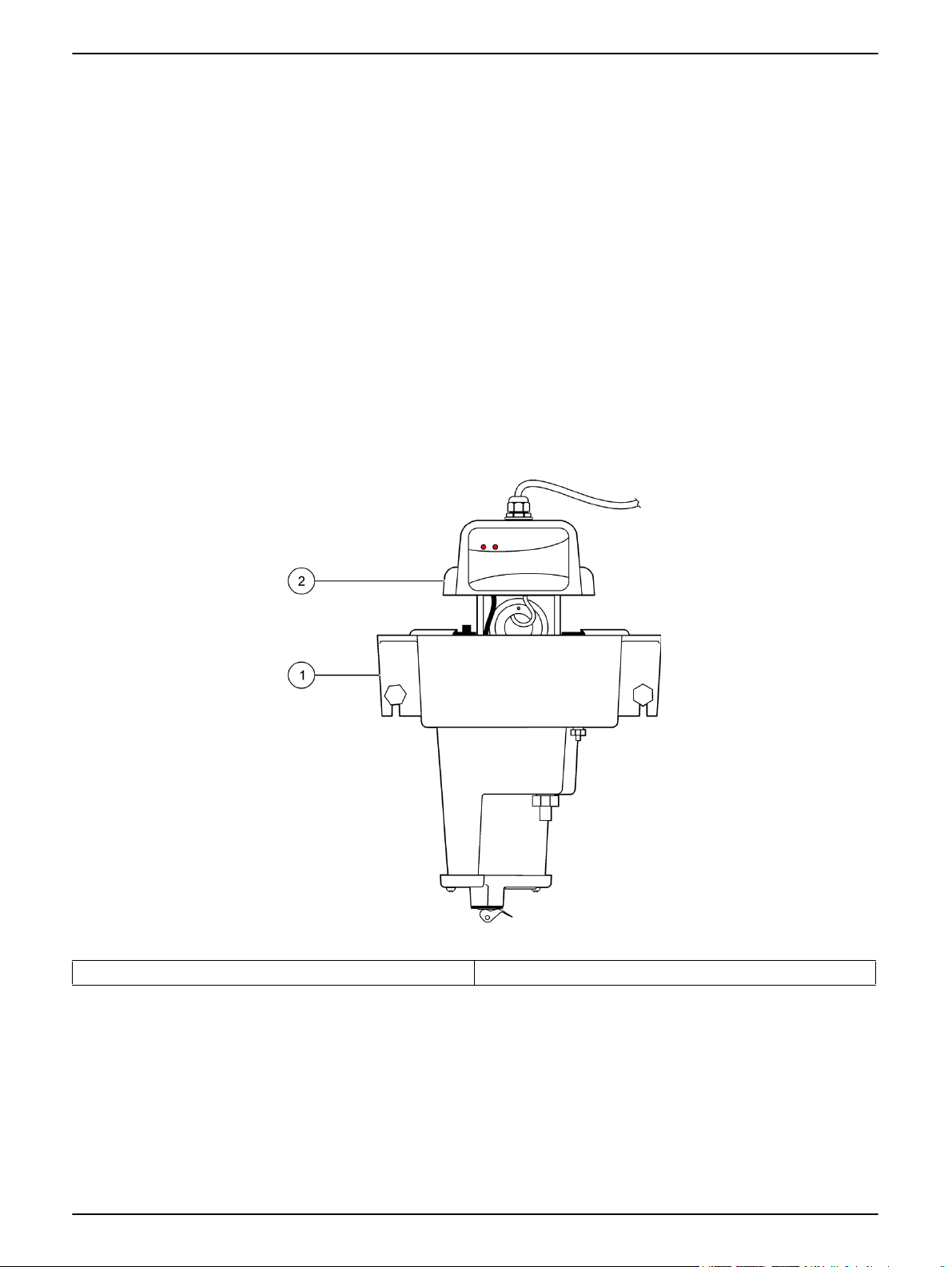
3. Remove the turbidimeter head. Refer to Figure 1 on page 3.
4. Remove the dry standard from the protective case and record the serial number
etched into the dry standard collar. Refer to Figure 2 on page 4. The serial number
must be entered to determine a baseline value.
5. Inspect the dry standard glass rod to make sure it is clean and free of chips and
scratches. Clean the device with the disposable wipes provided.
6. Dry the top
7. Insert the dry standard into the aperture plate. Make sure the alignment pin fits into the
notch. Refer to Figure 2 on page 4.
2
1
/3 of the dry standard and the top surface. Refer to Figure 2 on page 4.
Page 3
FT660 and FT660sc dry standard quick check verification
8. Rotate the dry standard approximately 1/8 of a turn to the right until the dry standard
locks into position. Refer to Figure 2 on page 4.
9. Dry off the remainder of the glass to remove any fingerprints and oils.
10. Place the turbidimeter head on the body. Make sure the head is correctly positioned
and press ENTER.
11. Enter the digits of the dry standard serial number and press ENTER.
12. Allow the instrument reading to stabilize. Press ENTER to accept the reading as the
baseline value.
Note: The user does have the option to push ENTER before the reading becomes stable.
However, this may cause inaccurate baseline values.
13. Remove the dry standard, replace the head and press ENTER to continue to
Measurement Mode. Place the dry standard back into the protective case.
Figure 1 Remove turbidimeter head
1 FT660 body 2 FT660 head
3
Page 4

FT660 and FT660sc dry standard quick check verification
.
Figure 2 Dry standard installation
1 Dry standard 6 Dry standard locking pin
2 Dry standard protective case 7 Aperture plate
3 Dry standard top surface 8 Turbidimeter head assembly
4 Disposable wipe 9 Aperture plate notch
5 Dry standard serial number
1.3 Perform a verification with the dry standard and the sc100 software
1. Choose MAIN MENU.
2. Choose SENSOR SETUP. Select the sensor for verification and press ENTER.
3. Choose CALIBRATE, VERIFICATION, PERFORM VERIFICATION.
4. Choose from Active, Hold, or Transfer outputs and press ENTER.
5. Select DRY for the verification type and press ENTER.
6. Verify that the serial number displayed matches the serial number etched on the dry
standard collar. Press ENTER.
7. Attach the dry standard to the turbidimeter head. Put the head on the instrument body
and push ENTER.
8. When the dry standard measurement is stable, push ENTER to accept the reading
shown. A GOOD VER (Good Verification) or BAD VER (Bad Verification) will appear.
A bad verification indicates the instrument failed to meet the PFC, or that the
instrument was unable to reach a stable reading.
Table 1 on page 6 can be used to interpret verification values and determine what
action should be taken. If the instrument consistently fails the verification process,
contact the manufacturer.
4
Page 5

FT660 and FT660sc dry standard quick check verification
9. When prompted, remove the dry standard and put the turbidimeter back on line. Push
ENTER.
10. Select the HOME key to show on-line measurements.
11. Wipe off the dry standard after removal and put it in the protective case.
Section 2 General procedure for dry standard verification without software
This procedure includes the initial assignment of the baseline value to the dry standard on
instruments without software. The procedure should be completed for each FT660 or
FT660sc laser nephelometer immediately after the instrument has been successfully
calibrated. The baseline value is used for instrument verifications performed between
calibrations.
Once the baseline value of the dry standard has been determined, manually record the
value. Also record the serial number of the dry standard and the serial number of the
FT660 instrument. A baseline value is valid only for the combination of dry standard and
instrument used to determine it.
Refer to Figure 2 on page 4 as necessary when performing the procedures below.
Note: When not in use, keep the dry standard in the protective case.
2.1 Assign a baseline value to the dry standard
1. Remove the dry standard from the protective case. Examine the dry standard to make
sure it is clean and free of chips or scratches.
2. Clean the dry standard with the disposable wipes provided.
3. Dry the top
4. Put the dry standard into the aperture plate. Make sure the alignment pin fits into the
notch. Refer to Figure 2 on page 4.
5. Turn the dry standard approximately
into position.
6. After the dry standard is attached to the turbidimeter head, clean the remainder of the
glass to remove fingerprints and oils.
7. Attach the turbidimeter head on the instrument body.
8. After the reading becomes stable, record the value shown in the display. This is the
first of 3 values which will be averaged to find a final baseline value.
1
/3 of the dry standard and the top surface.
1
/8 of a turn to the right to lock the dry standard
9. Remove and clean the dry standard. Attach the dry standard to the aperture plate and
put the turbidimeter head on the body. When the reading has stabilized, record the
value shown.
10. Repeat step 9 and record the value shown a third time.
11. Find the average of the three recorded values. This is the final baseline value for the
dry standard. This value will be compared to subsequent verification values for this
specific combination of dry standard and instrument.
5
Page 6

FT660 and FT660sc dry standard quick check verification
2.2 Verification procedure for the FT660 using the dry standard
1. Remove the dry standard from the protective case. Examine the glass and plastic to
make sure it is clean and free of chips and scratches.
2. Clean the device using the disposable wipes provided.
3. Dry the top
1
/3 of the dry standard and the top surface.
4. Put the dry standard into the aperture plate. Make sure the alignment pin fits into the
notch. Refer to Figure 2 on page 4.
5. Turn the dry standard approximately
1
/8 turn to the right to lock the dry standard into
position.
6. Dry off the remainder of the glass to remove fingerprints and oils.
7. Attach the turbidimeter head on the body.
8. When the reading becomes stable record the value shown.
9. Interpret the results. Refer to Table 1 as a guide. The table assumes a PFC of ±5
mNTU (the default value).
.
Table 1 Interpretation of values
Verification Value Interpretation Suggested Action
Within 5 mNTU of baseline Successful verification None
5 mNTU or greater below baseline Instrument out of calibration
Possible contamination of turbidimeter
5 mNTU or greater above baseline
body. Possible fluid on dry standard
optical surface.
Clean instrument and repeat
verification. Calibrate if necessary.
Clean body, bubble trap, detector and
dry standard. Calibrate instrument and
assign new baseline value.
Note: A significantly low value (25% or more below the expected value) can be an indication that the
light source or detector is failing. If the operator repeatedly experiences verification failures with
significantly low values, the instrument must be sent back to the manufacturer for repair.
Replacement parts and accessories
Description
FT660 sc Verification Quick Check (CVM) Kit, includes: 6735500
• Dry standard
• Protective case for dry standard
• Disposable wipes
• Instruction sheet
1
Aperture plate
for dry standard, with replacement screws 6735600
• Aperture plate replacement instruction sheet
1
Included on FT660 sc instruments made after April 2008
Item no.
6735800
6735400
2097000
DOC272.xx.90012
DOC273.xx.90049
6
Page 7

Contact Information
HACH Company
World Headquarters
P.O. Box 389
Loveland, Colorado
80539-0389 U.S.A.
Tel (800) 227-HACH
(800) -227-4224
(U.S.A. only)
Fax (970) 669-2932
orders@hach.com
www.hach.com
HACH LANGE GMBH
Willstätterstraße 11
D-40549 Düsseldorf
Tel. +49 (0)2 11 52 88-320
Fax +49 (0)2 11 52 88-210
info@hach-lange.de
www.hach-lange.de
DR. BRUNO LANGE AG
Juchstrasse 1
CH-8604 Hegnau
Tel. +41(0)44 9 45 66 10
Fax +41(0)44 9 45 66 76
info@hach-lange.ch
www.hach-lange.ch
Repair Service in the
United States:
HACH Company
Ames Service
100 Dayton Avenue
Ames, Iowa 50010
Tel (800) 227-4224
(U.S.A. only)
Fax (515) 232-3835
HACH LANGE LTD
Pacific Way
Salford
GB-Manchester, M50 1DL
Tel. +44 (0)161 872 14 87
Fax +44 (0)161 848 73 24
info@hach-lange.co.uk
www.hach-lange.co.uk
HACH LANGE FRANCE
S.A.S.
33, Rue du Ballon
F-93165 Noisy Le Grand
Tél. +33 (0)1 48 15 68 70
Fax +33 (0)1 48 15 80 00
info@hach-lange.fr
www.hach-lange.fr
Repair Service in Canada:
Hach Sales & Service
Canada Ltd.
1313 Border Street, Unit 34
Winnipeg, Manitoba
R3H 0X4
Tel (800) 665-7635
(Canada only)
Tel (204) 632-5598
Fax (204) 694-5134
canada@hach.com
HACH LANGE LTD
Unit 1, Chestnut Road
Western Industrial Estate
IRL-Dublin 12
Tel. +353(0)1 46 02 5 22
Fax +353(0)1 4 50 93 37
info@hach-lange.ie
www.hach-lange.ie
HACH LANGE SA
Motstraat 54
B-2800 Mechelen
Tél. +32 (0)15 42 35 00
Fax +32 (0)15 41 61 20
info@hach-lange.be
www.hach-lange.be
Repair Service in
Latin America, the
Caribbean, the Far East,
Indian Subcontinent, Africa,
Europe, or the Middle East:
Hach Company World
Headquarters,
P.O. Box 389
Loveland, Colorado,
80539-0389 U.S.A.
Tel +001 (970) 669-3050
Fax +001 (970) 669-2932
intl@hach.com
HACH LANGE GMBH
Hütteldorferstr. 299/Top 6
A-1140 Wien
Tel. +43 (0)1 9 12 16 92
Fax +43 (0)1 9 12 16 92-99
info@hach-lange.at
www.hach-lange.at
DR. LANGE NEDERLAND
B.V.
Laan van Westroijen 2a
NL-4003 AZ Tiel
Tel. +31(0)344 63 11 30
Fax +31(0)344 63 11 50
info@hach-lange.nl
www.hach-lange.nl
HACH LANGE APS
Åkandevej 21
DK-2700 Brønshøj
Tel. +45 36 77 29 11
Fax +45 36 77 49 11
info@hach-lange.dk
www.hach-lange.dk
HACH LANGE LDA
Av. do Forte nº8
Fracção M
P-2790-072 Carnaxide
Tel. +351 214 253 420
Fax +351 214 253 429
info@hach-lange.pt
www.hach-lange.pt
HACH LANGE KFT.
Hegyalja út 7-13.
H-1016 Budapest
Tel. +36 (06)1 225 7783
Fax +36 (06)1 225 7784
info@hach-lange.hu
www.hach-lange.hu
HACH LANGE AB
Vinthundsvägen 159A
SE-128 62 Sköndal
Tel. +46 (0)8 7 98 05 00
Fax +46 (0)8 7 98 05 30
info@hach-lange.se
www.hach-lange.se
HACH LANGE SP.ZO.O.
ul. Opolska 143 a
PL-52-013 Wrocław
Tel. +48 (0)71 342 10-83
Fax +48 (0)71 342 10-79
info@hach-lange.pl
www.hach-lange.pl
HACH LANGE S.R.L.
Str. Leonida, nr. 13
Sector 2
RO-020555 Bucuresti
Tel. +40 (0) 21 201 92 43
Fax +40 (0) 21 201 92 43
info@hach-lange.ro
www.hach-lange.ro
HACH LANGE S.R.L.
Via Riccione, 14
I-20156 Milano
Tel. +39 02 39 23 14-1
Fax +39 02 39 23 14-39
info@hach-lange.it
www.hach-lange.it
HACH LANGE S.R.O.
Lešanská 2a/1176
CZ-141 00 Praha 4
Tel. +420 272 12 45 45
Fax +420 272 12 45 46
info@hach-lange.cz
www.hach-lange.cz
HACH LANGE
8, Kr. Sarafov str.
BG-1164 Sofia
Tel. +359 (0)2 963 44 54
Fax +359 (0)2 866 04 47
info@hach-lange.bg
www.hach-lange.bg
HACH LANGE S.L.U.
Edif. Arteaga Centrum
C/Larrauri, 1C- 2ª Pl.
E-48160 Derio/Vizcaya
Tel. +34 94 657 33 88
Fax +34 94 657 33 97
info@hach-lange.es
www.hach-lange.es
HACH LANGE S.R.O.
Roľnícka 21
SK-831 07 Bratislava –
Vaj nory
Tel. +421 (0)2 4820 9091
Fax +421 (0)2 4820 9093
info@hach-lange.sk
www.hach-lange.sk
HACH LANGE SU
ANALİZ SİSTEMLERİ
LTD.ŞTİ.
Hilal Mah. 75. Sokak
Arman Plaza No: 9/A
TR-06550 Çankaya/ANKARA
Tel. +90 (0)312 440 98 98
Fax +90 (0)312 442 11 01
bilgi@hach-lange.com.tr
www.hach-lange.com.tr
HACH LANGE D.O.O.
Fajfarjeva 15
SI-1230 Domžale
Tel. +386 (0)59 051 000
Fax +386 (0)59 051 010
info@hach-lange.si
www.hach-lange.si
© Hach Company, 2008. All rights reserved. Printed in the U.S.A. Edition 1 March 2008 kw/kt
ΗΑCH LANGE E.Π.Ε.
Αυλίδος 27
GR-115 27 Αθήνα
Τηλ. +30 210 7777038
Fax +30 210 7777976
info@hach-lange.gr
www.hach-lange.gr
HACH LANGE E.P.E.
27, Avlidos str
GR-115 27 Athens
Tel. +30 210 7777038
Fax +30 210 7777976
info@hach-lange.gr
www.hach-lange.gr
Page 8

 Loading...