

Page 1

DOC026.98.80015
FL900 Series Flow Logger
06/2018, Edition 9
Basic User Manual
Basis-Benutzerhandbuch
Manuale di base per l'utente
Manuel d'utilisation de base
Manual básico del usuario
Manual Básico do Usuário
Grundläggande bruksanvisning
Temel Kullanım Kılavuzu
Osnovni uporabniški priročnik
Osnovni korisnički priručnik
Page 2

English..............................................................................................................................3
Deutsch.......................................................................................................................... 27
Italiano............................................................................................................................ 54
Français......................................................................................................................... 79
Español........................................................................................................................ 105
Português.................................................................................................................... 131
Svenska....................................................................................................................... 156
Türkçe...........................................................................................................................181
Slovenski..................................................................................................................... 205
Hrvatski........................................................................................................................ 230
2
Page 3

Table of contents
Specifications on page 3 Basic setup on page 21
General information on page 4 Site installation on page 22
Apply power to the Logger on page 9 Maintenance on page 23
System startup on page 12 Troubleshooting on page 24
Program a unit equipped with a modem on page 15 Replacement parts and accessories on page 25
Modbus communication on page 20
Additional information
Additional information is available on the manufacturer's website.
Specifications
Specifications are subject to change without notice.
Specification Details
Dimensions (W x D x H) 25.4 x 22 x 40 cm (10.0 x 8.7 x 16.0 in.)
Enclosure PC/ABS structural foam
Environmental rating NEMA 6P/IP68 (24 hours at 1.8 m (6 ft) submersion)
Weight (model FL900) 4.5 kg (10 lb) with no batteries, 6.3 kg (14 lb) with 2 batteries and 8.2 kg (18 lb)
Operating temperature –18 to 60 ºC (0 to 140 ºF) at 95% RH
Storage temperature –40 to 60 ºC (–40 to 140 ºF)
Power requirements 8 to 18 VDC from batteries or external power source, 2.5 W max
Battery life Varies with sensor type, logging intervals, telemetry and environment.
Installation category I
Protection class III
Pollution degree 4
Sensor ports 1, 2 or 4 ports
Connectors Stainless steel connectors
Datalog channels 16 maximum
Alarms Maximum of 16 channel alarms with high/high, high, low, low/low options.
with 4 batteries
For a 15 minute logging interval, with no modem, four 6 V lantern batteries at
room temperature:
• Flo-tote 3 sensor 306 days
• Area Velocity sensor with AV9000 Analyzer 296 days
• Flo-Dar sensor 185 days
• Ultrasonic sensor 456 days
Note: For longer deployments use with Long Life Battery, PN 8542900.
System alarms include low battery, low RTC battery, low slate memory, slate
memory full, sensor time out, sensor ID.
English 3
Page 4

Specification Details
Alarm actions Start the sampler, change the log interval, change the call interval, send an e-
Logging intervals 1, 2, 3, 4, 5, 6, 10, 12, 15, 20, 30 or 60 minutes
Data storage Event log: 1000 events maximum in non-volatile flash memory
PC communication USB
Remote communication
(optional)
Protocols Modbus RTU (RS232)
Timebase accuracy ±0.002%, synchronized every 24 hours with server software and modem
Supported sensors Flo-Dar, Flo-Dar with SVS, Flo-Tote, Rain Gauge, Ultrasonic, Submerged Area
Sampler interface Compatible with Sigma 900 Standard, Sigma 900 Max, Hach SD900 and
Certifications Logger: CE
Warranty 1 year
mail or a text message (SMS) from logger or server.
Note: SMS rates may apply. Not all alarm types may be available with all cellular carriers and
service plans.
Primary and secondary intervals for dynamic logging
Sample history: 2000 sample events maximum in non-volatile flash memory
Datalog: 325,000 data points; 1128 days for 3 channels at 15-minute log
intervals
RS232 (Baud rates: 9600, 19200, 38400, 57600, 115200)
Wireless modem: 3G, 4G LTE (Verizon); 3G, 4G LTE, PTCRB (USA and
Canada)
Mobile-Terminated SMS
Mobile-Originated SMS
Velocity1, Sigma 950
AS950 to support set point sampling, flow-pacing and sample history logging
Optional AC power supply: UL/CSA standards (cETLus)/CE
Modems: FCC, IC, others may be available—contact the manufacturer for more
information.
1
General information
In no event will the manufacturer be liable for direct, indirect, special, incidental or consequential
damages resulting from any defect or omission in this manual. The manufacturer reserves the right to
make changes in this manual and the products it describes at any time, without notice or obligation.
Revised editions are found on the manufacturer’s website.
Safety information
N O T I C E
The manufacturer is not responsible for any damages due to misapplication or misuse of this product including,
without limitation, direct, incidental and consequential damages, and disclaims such damages to the full extent
permitted under applicable law. The user is solely responsible to identify critical application risks and install
appropriate mechanisms to protect processes during a possible equipment malfunction.
Please read this entire manual before unpacking, setting up or operating this equipment. Pay
attention to all danger and caution statements. Failure to do so could result in serious injury to the
operator or damage to the equipment.
1
This device attaches through an external module.
4 English
Page 5

Make sure that the protection provided by this equipment is not impaired. Do not use or install this
equipment in any manner other than that specified in this manual.
Use of hazard information
D A N GE R
Indicates a potentially or imminently hazardous situation which, if not avoided, will result in death or serious injury.
Indicates a potentially or imminently hazardous situation which, if not avoided, could result in death or serious
injury.
Indicates a potentially hazardous situation that may result in minor or moderate injury.
Indicates a situation which, if not avoided, may cause damage to the instrument. Information that requires special
emphasis.
W A R NI N G
C A U TI O N
N O T I C E
Precautionary labels
Read all labels and tags attached to the instrument. Personal injury or damage to the instrument
could occur if not observed. A symbol on the instrument is referenced in the manual with a
precautionary statement.
This is the safety alert symbol. Obey all safety messages that follow this symbol to avoid potential
injury. If on the instrument, refer to the instruction manual for operation or safety information.
This symbol indicates that a risk of electrical shock and/or electrocution exists.
This symbol indicates the presence of devices sensitive to Electro-static Discharge (ESD) and
indicates that care must be taken to prevent damage with the equipment.
This symbol indicates radio waves.
Electrical equipment marked with this symbol may not be disposed of in European domestic or public
disposal systems. Return old or end-of-life equipment to the manufacturer for disposal at no charge to
the user.
Confined space precautions
D A N GE R
Explosion hazard. Training in pre-entry testing, ventilation, entry procedures, evacuation/rescue
procedures and safety work practices is necessary before entering confined spaces.
The information that follows is supplied to help users understand the dangers and risks that are
associated with entry into confined spaces.
On April 15, 1993, OSHA's final ruling on CFR 1910.146, Permit Required Confined Spaces, became
law. This standard directly affects more than 250,000 industrial sites in the United States and was
created to protect the health and safety of workers in confined spaces.
English
5
Page 6

Definition of a confined space:
A confined space is any location or enclosure that has (or has the immediate potential for) one or
more of the following conditions:
• An atmosphere with an oxygen concentration that is less than 19.5% or more than 23.5% and/or a
hydrogen sulfide (H2S) concentration that is more than 10 ppm.
• An atmosphere that can be flammable or explosive due to gases, vapors, mists, dusts or fibers.
• Toxic materials which upon contact or inhalation can cause injury, impairment of health or death.
Confined spaces are not designed for human occupancy. Confined spaces have a restricted entry
and contain known or potential hazards. Examples of confined spaces include manholes, stacks,
pipes, vats, switch vaults and other similar locations.
Standard safety procedures must always be obeyed before entry into confined spaces and/or
locations where hazardous gases, vapors, mists, dusts or fibers can be present. Before entry into a
confined space, find and read all procedures that are related to confined space entry.
Certification
Canadian Radio Interference-Causing Equipment Regulation, IECS-003, Class A:
Supporting test records reside with the manufacturer.
This Class A digital apparatus meets all requirements of the Canadian Interference-Causing
Equipment Regulations: CAN ICES-3(A)/NMB-3(A).
Cet appareil numérique de classe A répond à toutes les exigences de la réglementation canadienne
sur les équipements provoquant des interférences.
FCC Part 15, Class "A" Limits
Supporting test records reside with the manufacturer. The device complies with Part 15 of the FCC
Rules. Operation is subject to the following conditions:
1. The equipment may not cause harmful interference.
2. The equipment must accept any interference received, including interference that may cause
undesired operation.
Changes or modifications to this equipment not expressly approved by the party responsible for
compliance could void the user's authority to operate the equipment. This equipment has been tested
and found to comply with the limits for a Class A digital device, pursuant to Part 15 of the FCC rules.
These limits are designed to provide reasonable protection against harmful interference when the
equipment is operated in a commercial environment. This equipment generates, uses and can
radiate radio frequency energy and, if not installed and used in accordance with the instruction
manual, may cause harmful interference to radio communications. Operation of this equipment in a
residential area is likely to cause harmful interference, in which case the user will be required to
correct the interference at their expense. The following techniques can be used to reduce
interference problems:
1. Disconnect the equipment from its power source to verify that it is or is not the source of the
interference.
2. If the equipment is connected to the same outlet as the device experiencing interference, connect
the equipment to a different outlet.
3. Move the equipment away from the device receiving the interference.
4. Reposition the receiving antenna for the device receiving the interference.
5. Try combinations of the above.
Wireless modem certification
The device complies with Part 15 of the FCC Rules and Industry Canada license-exempt RSS
standard(s). Operation is subject to the following conditions:
6
English
Page 7

1. The equipment may not cause harmful interference.
2. The equipment must accept any interference received, including interference that may cause
undesired operation.
Changes or modifications to this wireless communication equipment not expressly approved by the
party responsible for compliance could void the user's authority to operate the equipment. Any
change to the equipment will void the Industry Canada certification and FCC grant. Changes and
modifications include any modifications to the wireless modems and associated antennas, including
antenna cables. Follow the manufacturer recommendations for product installation, configuration and
wireless operation.
Cellular devices
N O T I C E
Network and access point security is the responsibility of the customer that uses the wireless instrument. The
manufacturer will not be liable for any indirect, special, incidental or consequential damages caused by a breach
in network security.
Pacemaker precautions. If electromagnetic interference (EMI) occurs, it can either:
• Stop the stimulating pulses from the pacemaker that control the rhythm of the heart.
• Cause the pacemaker to supply the pulses irregularly.
• Cause the pacemaker to ignore the rhythm of the heart and supply pulses at a set interval.
Current research shows that cellular devices are not a significant health problem for most pacemaker
wearers. However, persons with pacemakers should use precautions to make sure that their device
does not cause a problem. Keep the device a minimum of 20 cm (7.9 in.) from the user.
Electromagnetic radiation hazard. Make sure that the antenna is kept at a minimum distance of 20 cm
(7.9 in.) from all personnel in normal use. The antenna cannot be co-located or operated in conjunction
with any other antenna or transmitters.
W A R NI N G
C A U TI O N
C A U TI O N
Electromagnetic radiation hazard. In portable applications, do not use the modem within 20 cm (7.9 in.)
of the user.
Regulatory RF device approvals
Modem MTSMC-LAT3 (Equipment Class: PCS Licensed Transmitter, LTE/3G module):
• FCC: Approved as a Modular Device with a TCB Grant of Authorization. FCC ID: RI7LE910NAV2
• IC: Approved as a Modular Device with Certificat D'Acceptabilite' Technique C-REL ID: 5131ALE910NAV2
Modem MTSMC-LVW3 (PCS Licensed Transmitter, LTE/3G module):
• FCC: Approved as a Modular Device with a TCB Grant of Authorization. FCC ID: RI7LE910SVV2
• IC: Approved as a Modular Device with Certificat D'Acceptabilite' Technique C-REL ID: 5131ALE910SVV2
Table 1 Cellular Modem: MTSMC-LAT3
FCC rule parts Frequency bands (MHz) Maximum output power (Watts)
22, 24, 27 700 (B12/ B13), 850 (B5), 1700 (B4), 1900 (B2) 0.232
Cellular Modem MTSMC-LAT3—FCC Grant Notes & Conditions :
English
7
Page 8
Single Modular Approval. Power output listed is conducted. This device is approved for mobile and
fixed use with respect to RF exposure compliance, and may only be marketed to OEM installers. The
antenna(s) used for this transmitter, as described in this filing, must be installed to provide a
separation distance of at least 20 cm from all persons. Installers and end-users must be provided
with operating conditions for satisfying RF exposure compliance. Maximum permitted antenna
gain/cable loss: 6.63 dBi for 700 MHz & 850 MHz; 6.00 dBi for 1700 MHz; 8.51 dBi for 1900 MHz.
Table 2 Cellular Modem: MTSMC-LVW3
FCC rule parts Frequency bands (MHz) Maximum output power (Watts)
24, 27 700 (B13), 1700 (B4), 1900 (B2) 0.219
Cellular Modem MTSMC-LVW3—FCC Grant Notes & Conditions :
Single Modular Approval. Power output listed is conducted. This device is approved for mobile and
fixed use with respect to RF exposure compliance, and may only be marketed to OEM installers. The
antenna(s) used for this transmitter, as described in this filing, must be installed to provide a
separation distance of at least 20 cm from all persons. Installers and end-users must be provided
with operating conditions for satisfying RF exposure compliance. Maximum permitted antenna
gain/cable loss: 6.94 dBi for 700 MHz; 6.00 dBi for 1700 MHz; 9.01 dBi for 1900 MHz.
Product overview
The FL900 series flow loggers are used in open-channel flow monitoring studies such as inflow &
infiltration (I&I), combined sewer overflow (CSO), capacity and planning and storm water runoff
monitoring.
Data is collected from attached sensors and logged for future retrieval. The sensors can be added or
changed in the field. Depending on the model, up to four sensors can be connected. The data can be
retrieved directly through a USB or RS232 cable or remotely through a wireless network with
FSDATA Desktop and FSDATA server software. The FL900 Series loggers can also connect to an
external power source, rain gauge or be used to pace a Sigma or Hach sampler.
The wireless option and the number of available connectors varies with the model of the logger.
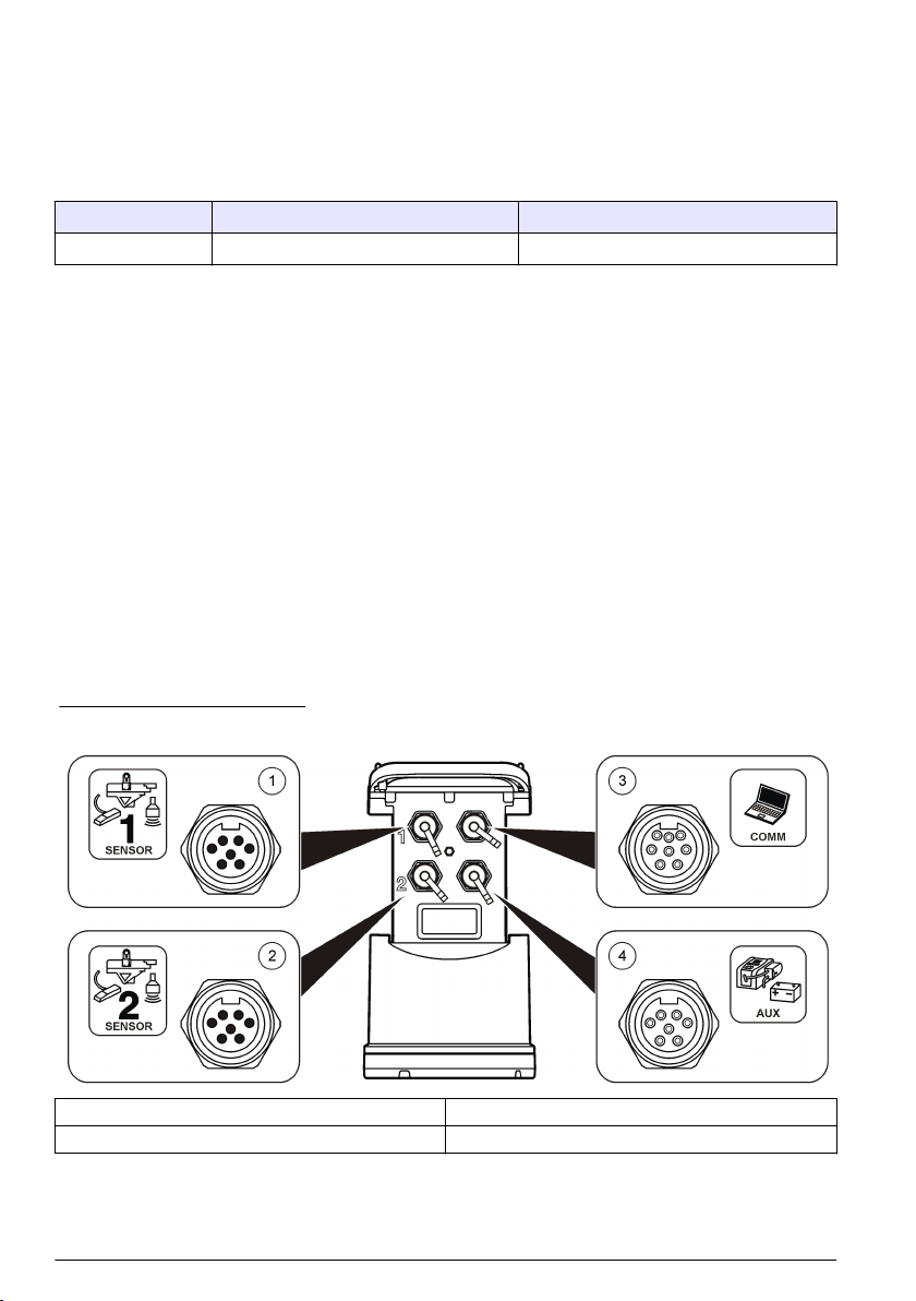
Refer to Figure 1 and Figure 2.
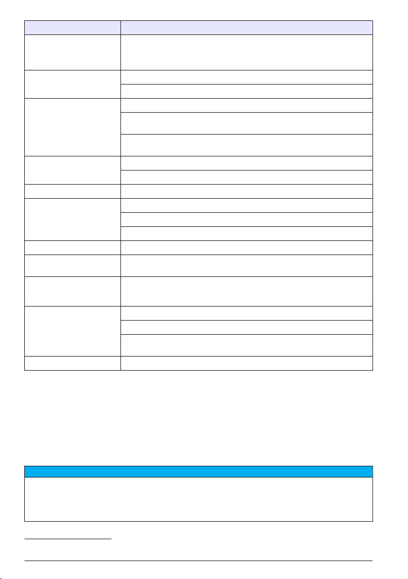
Figure 1 Connectors—side 1
1 Sensor (all models) 3 Computer—USB or RS232 cable (all models)
2 Sensor (FL902, FL904 only) 4 Auxiliary—external power or sampler (all but FL900)
8 English
Page 9

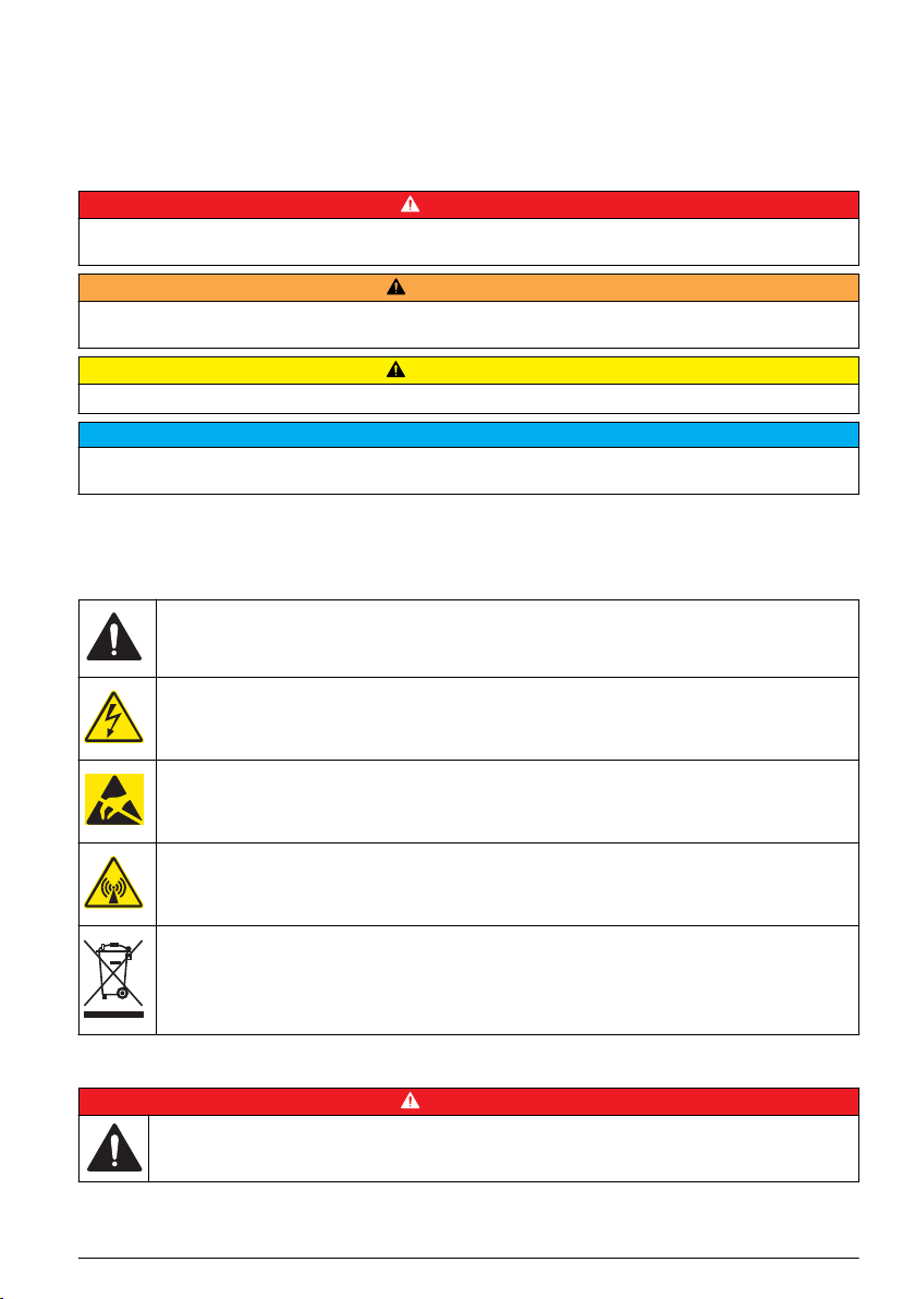
Figure 2 Connectors—side 2
1 Sensor (FL904 only) 3 Antenna option (all but FL900)
2 Sensor (FL904 only) 4 Rain gauge (all but FL900)
Product components
If any items are missing or damaged, contact the manufacturer or a sales representative
immediately.
Apply power to the Logger
Install the batteries
W A R NI N G
Explosion hazard. Incorrect battery installation can cause the release of explosive gases. Be sure that
the batteries are of the same approved chemical type and are inserted in the correct orientation. Do not
mix new and used batteries.
Fire hazard. Battery substitution is not permitted. Use only alkaline batteries.
Do not over-tighten the cover. Tighten until the cover just touches the O-ring, then tighten one-quarter to one-half
turn maximum from O-ring contact. Keep the O-ring lubricated with silicone grease.
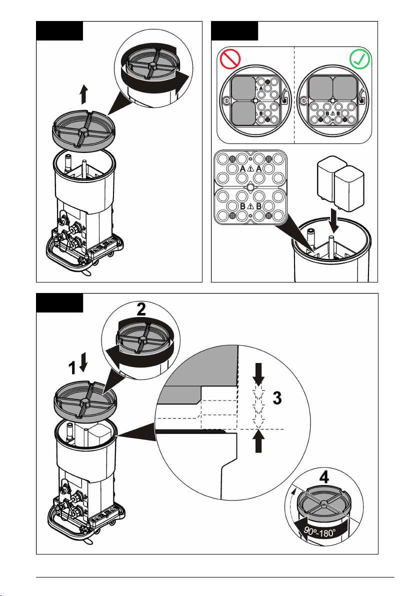
The instrument can use two or four 6 V batteries for power. Use two batteries for short-term use or
four batteries for long-term use (for battery life, refer to Specifications on page 3). When only two
batteries are used, put both batteries on the same side of the compartment (A-A or B-B). Refer to the
illustrated steps that follow.
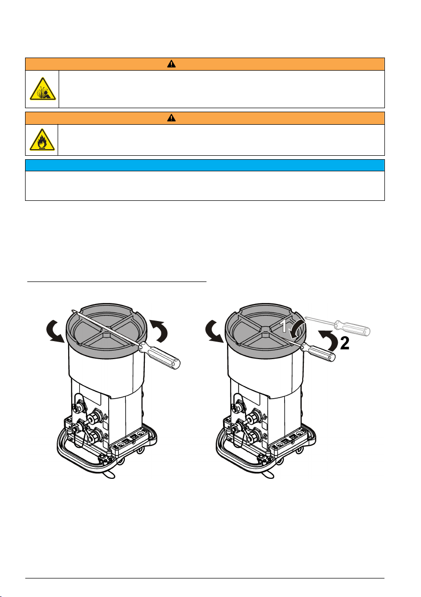
Changes in temperature and pressure can cause the battery compartment cover to be difficult to
remove by hand. If this occurs, a tool can be used to remove the cover (Figure 3).
W A R NI N G
N O T I C E
English
9
Page 10
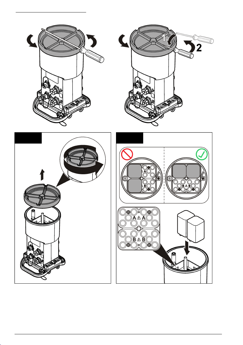
Figure 3 Battery cover removal
1 2
10 English
Page 11

3
Attach an external power supply (optional)
W A R NI N G
Potential explosion hazard. The instrument is not approved for use in hazardous locations.
The instrument can be powered by an external long-life battery, an AS950 power supply or other
source that can supply power in the specified range (refer to Specifications on page 3 and
Replacement parts and accessories on page 25). If the logger has both external power and internal
batteries, the internal batteries are used as an auxiliary power supply. When the external power falls
below approximately 9 V, the internal batteries supply power until the voltage from the external
source is above 9 V.
1. Install the external power source in a safe location near the logger. Be sure to obey all safety
precautions for the power supply.
2. Attach the cable from the power source to the AUX connector on the logger (Figure 4).
3. Apply power to the power source, if applicable.
English
11
Page 12
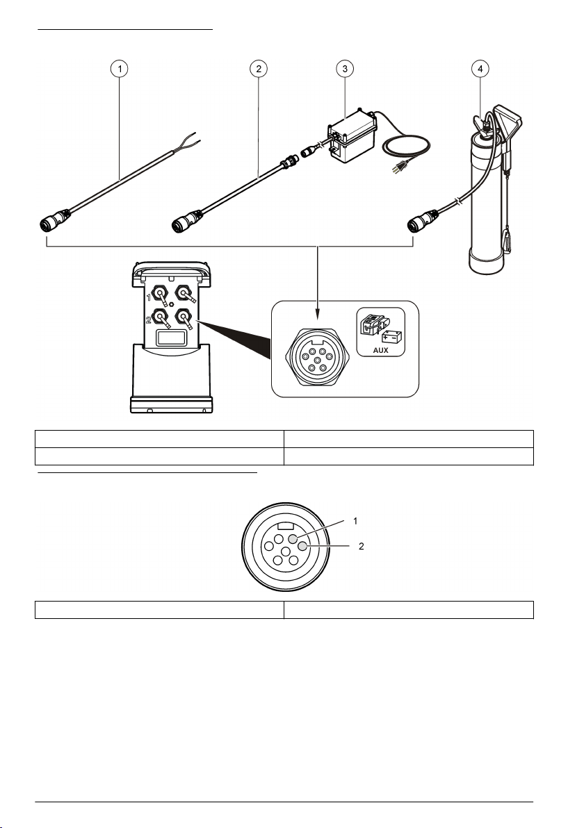
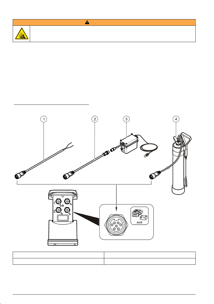
Figure 4 External power options
1 2-conductor power cable (Figure 5) 3 AS950 power supply
2 Power adapter cable 4 Long-life battery
Figure 5 2-conductor power cable wiring
1 Power—#16 AWG red 2 Common—#16 AWG black
System startup
Install FSDATA Desktop on a computer
Before the flow logger or sampler is connected to a computer, make sure that FSDATA Desktop is
installed on the computer. FSDATA Desktop is available at www.hachflow.com.
12
English
Page 13

Attach the logger to the computer
Pre-requisites: Make sure that FSDATA Desktop is installed on the computer.
Connect only one logger to the computer.
1. Attach the logger to the computer.
2. When a USB cable is attached for the first time, the Found New Hardware wizard opens. Run the
new hardware wizard to install the USB driver for the logger. When finished, the message “Your
new hardware is installed and ready to use” is shown. In the event the wizard does not run or the
install fails, contact technical support to assist with trouble shooting your specific operating
system.
Attach a sensor or external devices to the logger
Pre-requisite: Make sure that the connection status is "not connected".
W A R NI N G
Sensor Hazardous Locations and RF Exposure Hazards. Some sensors have RF radiation exposure
hazards and are used in explosive atmospheres. See sensor manual warnings and instructions before
connecting a sensor to the logger.
The number of sensors that can attach to the logger varies with the model of the logger. Some
sensors must attach to an external module that is used as an interface between the sensor and the
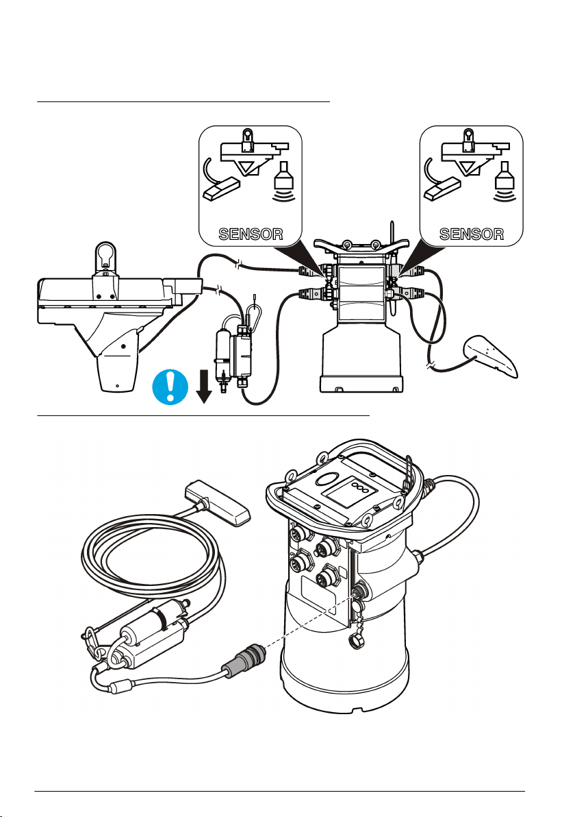
logger. Figure 7 shows the AV9000 Area Velocity Analyzer module on the side of the logger and the
connection to a submerged area/velocity sensor.
1. If the sensor cable has connectors on both ends, attach the cable to the sensor first.
2. Attach the sensor (or module) to any SENSOR port on the logger (Figure 6 or Figure 7). Tighten
the connector by hand.
Note: For rain gauges, attach the sensor to the RAIN connector.
3. If the sensor uses an external module, attach the module to the logger, then attach the sensor to
the module (Figure 7).
4. If the sensor cable has a desiccant hub, align the desiccant hub vertically and make sure that the
air port points down (Figure 6).
Figure 6 Attach a sensor to the logger
English 13
Page 14
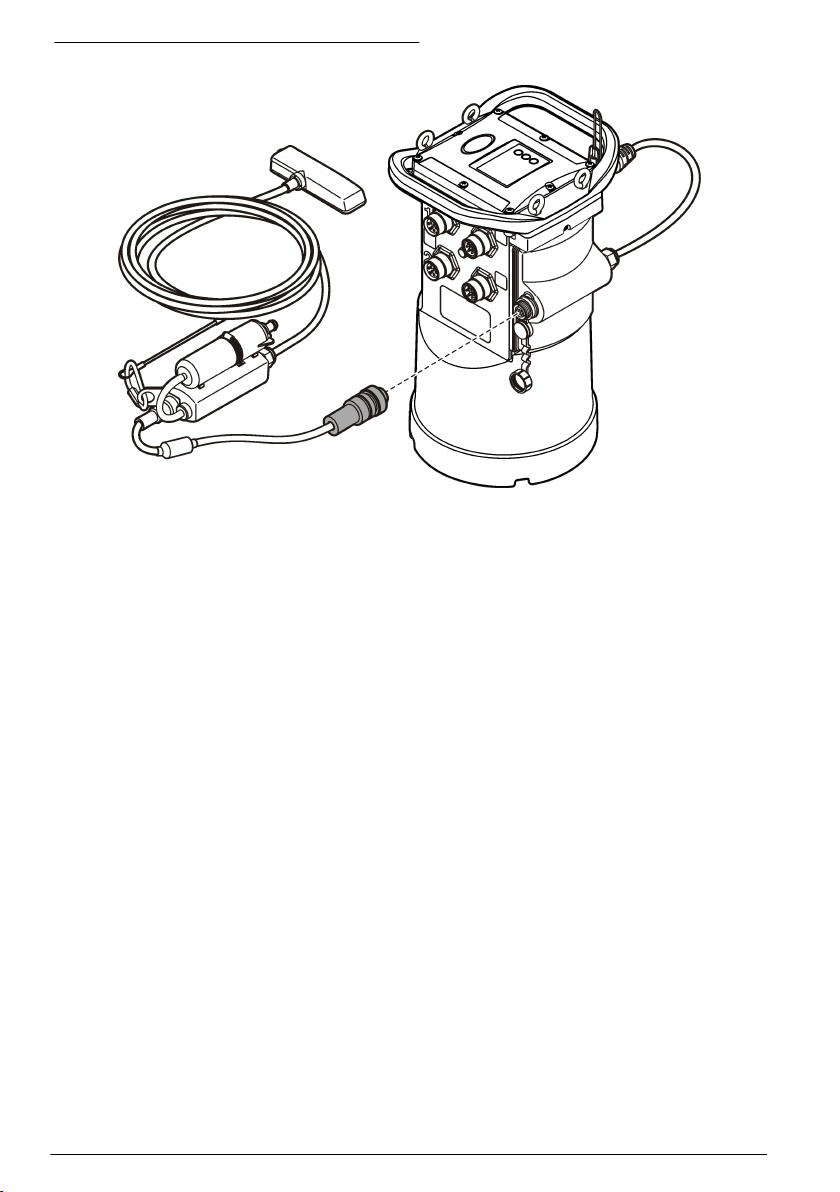
Figure 7 Attach a sensor to an external module
Attach an external module
An external module must be used as an interface between some sensor types and the logger. The
external module is mounted on the side of the logger (Figure 7 on page 14). Refer to the
documentation that is supplied with the module for mounting instructions.
Attach a sampler
The logger can attach to a Sigma 900 Standard, Sigma 900 Max, Hach SD900 or Hach
AS950 sampler for flow-paced and set point sampling. Connect the AUX port on the logger to the
auxiliary port on the sampler using a full auxiliary cable. If it is necessary to externally power the
logger while connected to an AS950 sampler, use the power input aux cable assembly. To make a
sampler program, refer to the documentation supplied with the sampler.
User interface
The indicators on the user interface show the status of the instrument and the modem. Refer to
Figure 8 and Table 3.
14
English
Page 15

Figure 8 User interface
1 Instrument without modem 2 Instrument with modem
Table 3 LED status indicators
Indicator LED color Description
Green Flashes every 3 seconds during normal operation. Flashes every
Red Flashes when an attached sensor does not agree with the logger
Green Stays green during a call to the server.
Red Flashes red if the call to the server failed.
15 seconds during sleep mode.
program, an expected sensor is not found or the sensor operation has
failed.
Program a unit equipped with a modem
C A U TI O N
Electromagnetic radiation hazard. Make sure that the antenna is kept at a minimum distance of 20 cm
(7.9 in.) from all personnel in normal use. The antenna cannot be co-located or operated in conjunction
with any other antenna or transmitters.
For units without a modem, refer to Basic setup on page 21. For units that come with activated
modem accounts2, go to Add the logger to the FSDATA Server on page 18.
Set up the wireless account
Note: Adequate cellular coverage from the selected carrier must be verified for each site before a logger with a
cellular modem is purchased.
Network and access point security is the sole responsibility of the customer using the wireless instrument. The
manufacturer will not be liable for any indirect, special, incidental or consequential damages caused by a breach
in network security.
When the logger has a modem, data can be sent from the logger to the internet for remote access.
The user must first open an account with a mobile (wireless) provider. The instrument is then
registered to the data-hosting server (FSDATA), and the applicable communication settings are
programmed into the logger with FSDATA Desktop. If the modem was activated at the factory, go to
Add the logger to the FSDATA Server on page 18.
Pre-requisite: Make sure that the logger, logger test certificate and antenna are nearby.
2
The units that come with activated modem accounts have part numbers with .AX, .AR, .VX,
or .VR as the last digits.
N O T I C E
English 15
Page 16

Note: For optimal troubleshooting, install the FSDATA Desktop driver, add the logger to the FSDATA server, and
verify telemetry before visiting the deployment site.
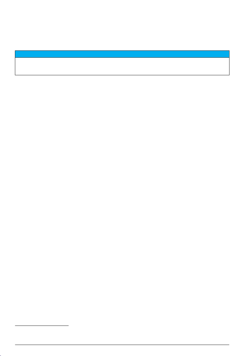
1. Gather your account information.
a. Find the IMEI number from the label. Refer to Figure 9.
b. Find the modem carrier model from the label.
2. Contact a wireless provider to start service on the modem. Make sure the wireless provider
matches the modem type in the logger, LVW3 = Verizon or LAT3 = PTCRB (AT&T, T-Mobile,
etc.). Request a data plan with a minimum 10 MB of data per month and SMS. (SMS is optional
but required to transmit alarm notifications to an email or mobile number).
a. Give the IMEI number to the provider. If requested, give the carrier model, also found on the
transmitter label.
b. Record the phone number for the modem.
3. Use the modem diagnostics in FSDATA Desktop to verify operation. Refer to the FSDATA
Desktop documentation.
Figure 9 Transmitter Label Examples
Install a SIM card
N O T I C E
Potential Instrument Damage. Delicate internal electronic components can be damaged by static
electricity, resulting in degraded performance or eventual failure.
N O T I C E
The instrument enclosure can break if the cover screws are over-tightened. Tighten the cover screws by hand
with a maximum torque of 2.0 Nm (20 in./lb). Make sure that the gasket is lubricated with grease.
Install a SIM card from the mobile carrier. Refer to the illustrated steps that follow. Make sure that the
PIN of the SIM card is disabled, and that the SIM card is for 4G LTE data.
16
English
Page 17

1 2
3 4
English 17
Page 18

Attach an antenna (wireless option)
C A U TI O N
Electromagnetic radiation hazard. Make sure that the antenna is kept at a minimum distance of 20 cm
(7.9 in.) from all personnel in normal use. The antenna cannot be co-located or operated in conjunction
with any other antenna or transmitters.
An antenna can be attached to the instrument for wireless communication. Various antenna options
are available. Refer to Replacement parts and accessories on page 25. Attach an antenna directly
to the logger or attach an antenna cable to the ANTENNA connector (Figure 10).
Figure 10 Attach the blade antenna
Add the logger to the FSDATA Server
Pre-requisite: Serial number of the logger
Figure 11 Serial number location
N O T I C E
Be sure to enter the serial number and SVC correctly to prevent communication failure.
1. Go to the website http://fsdata.hach.com to access the FSDATA server.
2. Enter the user name and password:
• User name—the default user name is the 8-digit customer ID number
• Password—the default password is HachWebData
3. Go to Instruments>Instrument Manager.
4. Record the SVC (Server Verification Code) from the upper left corner of the screen:
_______________________
18
English
Page 19

5. Click ADD NEW. The Add Instrument window opens.
6. Enter the serial number (SN) of the logger (Figure 11).
7. Select the Instrument Type.
8. Select the Active check box and click OK. The instrument is shown in the Instrument Manager.
Configure the logger for remote communication
Pre-requisites: The logger must be attached to the computer. An account with a network provider
must be set up, and the server must be configured.
The settings for remote communication must be entered into FSDATA Desktop and then written to
the logger.
1. Start a communication session with the logger:
a. Open FSDATA Desktop.
b. Click CONNECT. The Connect to Instrument window opens.
c. Click the FL900 button.
d. Select the port on the computer where the logger is attached (serial or USB), then click
Connect.
Note: If the sensor mismatch message is shown, select "Create new program based on sensors
connected."
e. Make sure that the connection status shows "connected".
2. Go to the Communications tab. Enter the information for the desired site. Select Time Zone.
3. Complete the Remote Settings information:
Option Description
Verizon 4G No additional configuration is necessary.
LAT3 4G Select the network provider and enter the user name and password, if applicable.
Primary Call Interval The frequency that the logger calls the server.
Secondary call interval The frequency that the logger calls the server during an alarm condition.
Server Verification Code The code that specifies which account on the FSDATA server the logger belongs
4. Click WRITE TO LOGGER to save the settings. A message window is shown:
Option Description
Warning: all data
will be lost.
Continue?
Set Logger Clock Synchronize to Computer Clock—the logger uses the date and time settings of the
to. The server cannot store data without this code.
All data that is stored in the logger is erased when a program is written to the logger.
To save the data, select No and download the data to a safe location. Select Yes to
erase all data and update the logger with the new program.
computer. Set Logger Clock—the logger uses the date and time settings that are set
by the user. If the unit has a modem, the logger automatically uses the date time
settings of the server.
Verify the telemetry (wireless option)
The user can manually send a call to the server to make sure that the network communication is
good.
1. Temporarily attach the antenna to the logger to test the antenna and the cell coverage at the site
location before installation.
2. Touch the magnet to the call initiation target (Figure 12). The modem LED indicator changes to
green.
3. Look at the modem LED indicator during the call (45 to 90 seconds) and wait for a change:
• LED goes off—the call to the server was successful.
English
19
Page 20

• LED flashes red—the call to the server failed.
Note: If the connection failed, refer to Troubleshooting on page 24 for more information.
Figure 12 Call the server
1 Call initiation target 2 Magnet
Verify the telemetry with FSDATA Desktop
1. In FSDATA Desktop, select Communications>Modem Diagnostics.
2. Make sure the registration status is either home or roaming. If blank or "identify" is shown, the
connection has failed.
3. Adjust the antenna for optimum signal strength and quality.
4. Click Call Server to make a call to the network.
A pop up screen will indicate success or failure.
Troubleshooting telemetry
• Make sure the SVC is correct.
• Make sure the serial number is registered and active on the host server.
• Make sure the modem is enabled and the Hach IP address has been correctly entered.
• If the problem persists, contact technical support.
Use the mobile SMS option
Configure the FL900 modem to send or receive SMS messages (optional). Refer to FSDATA
Desktop documentation for configuration information.
Modbus communication
The Modbus protocol can be used for communication with this instrument. Attach an external
network device, such as a PLC, to the RS232 interface on the instrument to read data as it is logged.
Contact technical support for more information on Modbus communications.
Note: Historical data cannot be read with Modbus communication.
20
English
Page 21

Basic setup
The information in this manual can be used to make a simple program for the logger and to calibrate
the sensors. Refer to the FSDATA Desktop documentation for advanced options. Complete the
sections in the order that they are shown.
Make a basic logger program
A basic program must be written to the logger to specify the channels to be logged.
1. Open a communication session with the logger:
a. Open FSDATA Desktop.
b. Click CONNECT. The Connect to Instrument window opens.
c. Click the FL900 button.
d. Select the port on the computer where the logger is attached (serial or USB), then click
CONNECT.
Note: If the sensor mismatch message is shown, select "Create new program based on sensors
connected."
e. Make sure that the connection status shows "connected".
2. Complete the information in the General Settings tab.
Option Description
Site Identification Enter a unique name for the site.
3. Select the channels to be logged in the Select channels to log section:
a. Expand the tree for the Logger channel group. The Power Supply channel is always shown in
this group. Logging the power supply will provide values for the battery level. An alarm could
be set at a specific level to alert the account manager of a low level, thus prompting a field
visit to change the batteries and prevent lost data. If the logger contains a port for a rain
gauge, the Rain channel is also shown. To include a Logger channel in the datalog, select the
check box next to the channel name.
b. Expand the tree for each Port[1](Sensor Name) channel group to view the available channels
for the sensor. If the check box next to Logger or Port[1] is selected, all of the channels in the
group are automatically selected.
c. To include a Sensor channel in the datalog, select the check box next to the channel name.
The log channel count increases each time a channel is selected.
Note: For loggers with multiple sensor ports, the port number is added to the channel name. For example,
Velocity 3 is the velocity channel name for sensor port 3.
4. To set the logging interval for a channel group:
a. Click on the channel group name, for example Port1 (Flo-Dar). The logging intervals are
shown.
English
21
Page 22

b. Select the interval from the drop-down list. The primary logging interval is used for normal
operation. The secondary logging interval is used during alarm conditions.
Note: The logging interval cannot be set for an individual sensor channel.
5. Click WRITE TO LOGGER to save the settings. A message window is shown:
Option Description
Warning: all data
will be lost.
Continue?
Set Logger Clock Synchronize to Computer Clock—the logger uses the date and time settings of the
All data that is stored in the logger is erased when a program is written to the logger.
To save the data, select No and download the data to a safe location. Select Yes to
erase all data and update the logger with the new program.
computer. Set Logger Clock—the logger uses the date and time settings that are set
by the user. If the unit has a modem, the logger automatically uses the date time
settings of the server.
Calibrate the sensor with the Cal Wizard
Pre-requisite: The logger must be connected to the computer and must be online for calibration.
The sensor can be configured and calibrated with the calibration wizard.
1. Click the Sensors tab.
2. Click on Sensor Port[1] (sensor name).
3. Click on the CAL WIZARD button. The Calibration Wizard window opens.
4. Select the options on each screen. When the Calibration Complete screen is shown, click
FINISH.
5. Click WRITE TO LOGGER to save the settings. A message window is shown:
Option Description
Warning: all data
will be lost,
Continue?
Set Logger Clock Synchronize to Computer Clock—the logger uses the date and time settings of the
All data that is stored in the logger is erased when a program is written to the logger.
To save the data, select No and download the data to a safe location. Select Yes to
erase all data and update the logger with the new program.
computer. Set Logger Clock—the logger uses the date and time settings that are set
by the user. If the unit has a modem, the logger automatically uses the date and time
settings of the server.
The installation is complete. The Status light should flash green if the programming was successful.
Site installation
W A R NI N G
Multiple hazards. Only qualified personnel must conduct the tasks described in this section of the
document.
Hang from a cable
N O T I C E
Do not use the handles to hang the logger. The handles are not designed to hold the weight of the logger.
The logger can hang from a cable for installation in an area such as a manhole.
1. Connect a cable to the eye bolts on the top of the logger. Refer to Figure 13.
2. Hang the cable from a strong support such as an optional spanner bar.
22
English
Page 23

Figure 13 Hang the logger from a cable
Install on a wall bracket
The logger can be attached to a wall, pole or ladder. Refer to the documents that are supplied with
the hardware for installation instructions.
Maintenance
W A R NI N G
Multiple hazards. Only qualified personnel must conduct the tasks described in this section of the
document.
W A R NI N G
Biological hazard. Obey safety handling protocols and wear all of the personal protective equipment
required when handling an instrument that may have come in contact with biological hazardous
materials. Wash and decontaminate the instrument with a disinfectant soap solution and rinse with hot
water before maintenance or shipping.
Electromagnetic radiation hazard. Make sure that the antenna is kept at a minimum distance of 20 cm
(7.9 in.) from all personnel in normal use. The antenna cannot be co-located or operated in conjunction
with any other antenna or transmitters.
Clean the instrument
Clean the exterior of the instrument with a moist cloth and a mild soap solution and then wipe the
instrument dry as necessary.
C A U TI O N
English
23
Page 24

Replace the batteries
Replace the batteries with the same type and rating. Refer to Install the batteries on page 9 and
Specifications on page 3.
Replace the desiccant
The desiccant is located in the battery compartment. To remove the battery cover, refer to Install the
batteries on page 9. The desiccant absorbs moisture from the air and prevents corrosion to the
instrument components. The desiccant beads change color when they become saturated. Replace
the desiccant when the beads change from a yellow to a green color (refer to Figure 14). As a best
practice, replace the desiccant when the batteries are replaced.
Figure 14 Desiccant replacement
Troubleshooting
If problems occur in the system, try to find whether the problem is with the sensor, the logger or the
cable connections.
• Examine all connections to the sensors. Make sure all connections are tight.
• Remove and examine the sensor connectors for moisture. Clean and dry if necessary.
• Examine the sensors for debris and remove the debris.
• Examine the Event Log for problem events.
Communication failure
If a call was sent to the server but the connection failed, complete the following tasks:
• Disconnect and apply power to the instrument.
• Adjust the antenna to increase the signal strength.
• Log on to the server and make sure that the serial number was entered correctly and that the SVC
used for configuration was recorded correctly.
• Make sure that the communication settings were entered correctly in the FL900 driver window.
• Connect the logger to the computer and open a communications session. In the FL900 driver
window, click on the Diagnostics tab and then the Modem menu. The Registration Status should
be Home.
• If there is no resolution, call technical support.
24
English
Page 25

Replacement parts and accessories
Note: Product and Article numbers may vary for some selling regions. Contact the appropriate distributor or refer to
the company website for contact information.
Replacement parts
Description Item no.
Battery compartment cover 8524400
Battery compartment cover, O-ring 8533400
Desiccant cap assembly (battery compartment desiccant) 8754900
Desiccant tube assembly (battery compartment desiccant) 8535200
Desiccant, replacement beads, 680 g (1.5 lb) 8755500
Eyebolts, 1/4–20 x 2.5-in. stainless steel 8535500
Gasket, top cover 8533300
Enclosure screw, #10–14 x 1 in. 8753300
Logger handle 8524200
Lubricant, silicone, 0.25 oz 000298HY
Magnet assembly 8537800
Cap and lanyard for the Sensor, Comm or Aux connectors 8535000
Cap and lanyard for the rain gauge connector 9492500
Power
Description Item no.
Battery, 6 V lantern 11013M
Battery, long-life alkaline 8542900
Long-life alkaline battery pack top cap adapter and cable 8543000
Cable assembly, external power, 2.7 m (9 ft) 8528700
Cable assembly, external power, 7.6 m (25 ft) 8528701
Mounting hardware
Description Item no.
Wall-mount bracket without ladder hanger 8542700
Wall-mount bracket adapter 8543800
Antennas
Description Item no.
Blade, 3G/4G LTE, 3 dBi 8623800
Mini-wing, 2G/3G/4G LTE, 2.5 m (8.2 ft) cable, 5.5 dBi 8624000
English 25
Page 26

Antennas (continued)
Description Item no.
Burial, 3G/4G LTE, 3 m (9.8 ft) cable, 3 dBi 8624200
Manhole Lid, 3G/4G LTE, 3 m (9.8 ft) cable, 3 dBi 8624400
Auxiliary/Sampler cables
Description Item no.
Cable, auxiliary, multi-purpose half, 7 pin, 2.7 m (9 ft) 8528500
Cable, auxiliary, multi-purpose half, 7 pin, 7.6 m (25 ft) 8528501
Cable, FL900 logger to AS950 AUX port, 7 pin, 2.7 m (9 ft) 9500700
Cable, FL900 logger to AS950 AUX port, 7 pin, 7.6 m (25 ft) 9500701
Cable assembly, power input AUX, AS950-FL900 with power adapter 8322800
26 English
Page 27

Inhaltsverzeichnis
Technische Daten auf Seite 27 Grundlegende Einrichtung auf Seite 47
Allgemeine Informationen auf Seite 28 Installation am Standort auf Seite 49
Verbinden des Loggers mit der Stromversorgung auf Seite 34 Wartung auf Seite 50
Inbetriebnahme auf Seite 37 Fehlersuche und -behebung auf Seite 51
Programmieren eines Geräts mit einem Modem auf Seite 39 Ersatzteile und Zubehör auf Seite 52
Modbus-Kommunikation auf Seite 46
Zusätzliche Informationen
Zusätzliche Informationen finden Sie auf der Website des Herstellers.
Technische Daten
Änderungen vorbehalten.
Technische Daten Details
Abmessungen (B x T x H) 25,4 x 22 x 40 cm (10,0 x 8,7 x 16,0 Zoll)
Gehäuse PC/ABS Strukturschaum
Umweltverträglichkeit NEMA 6P/IP68 (24 Stunden beim Untertauchen bis 1,8 m (6 Fuß))
Gewicht (Modell FL900) 4,5 kg (10 lb) ohne Batterien, 6,3 kg (14 lb) mit 2 Batterien und 8,2 kg (18 lb) mit
Betriebstemperatur -18 bis 60 ºC (0 bis 140 ºF) bei 95 % relative Luftfeuchtigkeit
Lagertemperatur -40 bis 60 ºC (-40 bis 140 ºF)
Stromanforderungen 8 bis 18 V Gleichstrom von Batterien oder externer Stromquelle, 2,5 W max.
Batterielebensdauer Variiert je nach Sensortyp, Protokollierungsintervallen, Telemetrie und
Installationskategorie I
Schutzklasse III
Verschmutzungsgrad 4
Sensor-Ports 1, 2 oder 4 Ports
Anschlüsse Edelstahl-Anschlüsse
Datalog-Kanäle Maximal 16
Alarme Maximal 16 Kanalalarme mit den Optionen hoch/hoch, hoch, niedrig,
4 Batterien
Umgebung.
Bei einem 15-minütigen Protokollierungsintervall ohne Modem und mit vier 6-V-
Laternenbatterien bei Raumtemperatur:
• Flo-Tote 3 Sensor 306 Tage
• Flächengeschwindigkeitssensor mit AV9000 Analysator 296 Tage
• Flo-Dar Sensor 185 Tage
• Ultraschallsensor 456 Tage
Hinweis: Verwenden Sie für längere Aufstellungszeiten Langzeitbatterien: PN 8542900.
niedrig/niedrig. Systemalarme, einschließlich: niedriger Batteriestand, niedriger
RTC-Batteriestand, niedriger Slate-Speicher, Slate-Speicher voll, SensorZeitüberschreitung, Sensor-ID.
Deutsch 27
Page 28
Technische Daten Details
Alarmaktionen Probenehmer starten, Aufzeichnungsintervall ändern, Anrufintervall ändern, E-
Aufzeichnungsintervalle 1, 2, 3, 4, 5, 6, 10, 12, 15, 20, 30 oder 60 Minuten
Datenspeicher Ereignisprotokoll: 1000 Ereignisse maximal in nicht flüchtigem Flash-Speicher
PC-Kommunikation USB
Fernkommunikation (optional) Funkmodem: 3G, 4G LTE (Verizon); 3G, 4G LTE, PTCRB (USA und Kanada)
Protokolle Modbus RTU (RS232)
Genauigkeit der Zeitbasis ±0,002 %, alle 24 Stunden mit Serversoftware und Modem synchronisiert
Unterstützte Sensoren Flo-Dar, Flo-Dar mit SVS, Flo-Tote, Niederschlagsmesser, Ultraschall,
Schnittstelle für Probengeber Kompatibel mit Sigma 900 Standard, Sigma 900 Max, Hach SD900 und
Zertifizierungen Logger: CE
Garantie 1 Jahr
Mail oder SMS vom Probenehmer oder Server senden.
Hinweis: Es könnten Kosten für das Senden von SMS entstehen. Möglicherweise sind nicht
alle Alarmtypen bei allen Mobilfunkanbietern und in allen Tarifen verfügbar.
Primäre und sekundäre Intervalle für dynamische Datenaufzeichnung
Probenverlauf: 2000 Probenereignisse maximal in nicht flüchtigem FlashSpeicher
Datenprotokoll: 325.000 Datenpunkte, 1128 Tage für 3 Kanäle in 15-minütigen
Aufzeichnungsintervallen
RS232 (Baudraten: 9600, 19200, 38400, 57600, 115200)
SMS an Mobiltelefon
SMS von Mobiltelefon
Geschwindigkeit eingetauchte Flächen1, Sigma 950
AS950 zur Unterstützung von Sollwert-Entnahmen, Strömungsmessung und
Aufzeichnung des Probenverlaufs
Optionale Netzstromversorgung: UL/CSA-Standards (cETLus)/CE
Modems: FCC, IC. Möglicherweise sind auch andere erhältlich. Weitere
Informationen erhalten Sie vom Hersteller.
1
Allgemeine Informationen
Der Hersteller ist nicht verantwortlich für direkte, indirekte, versehentliche oder Folgeschäden, die
aus Fehlern oder Unterlassungen in diesem Handbuch entstanden. Der Hersteller behält sich
jederzeit und ohne vorherige Ankündigung oder Verpflichtung das Recht auf Verbesserungen an
diesem Handbuch und den hierin beschriebenen Produkten vor. Überarbeitete Ausgaben der
Bedienungsanleitung sind auf der Hersteller-Webseite erhältlich.
Sicherheitshinweise
H I N W E I S
Der Hersteller ist nicht für Schäden verantwortlich, die durch Fehlanwendung oder Missbrauch dieses Produkts
entstehen, einschließlich, aber ohne Beschränkung auf direkte, zufällige oder Folgeschäden, und lehnt jegliche
Haftung im gesetzlich zulässigen Umfang ab. Der Benutzer ist selbst dafür verantwortlich, schwerwiegende
Anwendungsrisiken zu erkennen und erforderliche Maßnahmen durchzuführen, um die Prozesse im Fall von
möglichen Gerätefehlern zu schützen.
1
Dieses Gerät wird über ein externes Modul angeschlossen.
28 Deutsch
Page 29
Bitte lesen Sie dieses Handbuch komplett durch, bevor Sie dieses Gerät auspacken, aufstellen oder
bedienen. Beachten Sie alle Gefahren- und Warnhinweise. Nichtbeachtung kann zu schweren
Verletzungen des Bedieners oder Schäden am Gerät führen.
Stellen Sie sicher, dass die durch dieses Messgerät bereitgestellte Sicherheit nicht beeinträchtigt
wird. Verwenden bzw. installieren Sie das Messsystem nur wie in diesem Handbuch beschrieben.
Bedeutung von Gefahrenhinweisen
G E F AH R
Kennzeichnet eine mögliche oder drohende Gefahrensituation, die, wenn sie nicht vermieden wird, zum Tod oder
zu schweren Verletzungen führt.
Kennzeichnet eine mögliche oder drohende Gefahrensituation, die, wenn sie nicht vermieden wird, zum Tod oder
zu schweren Verletzungen führen kann.
Kennzeichnet eine mögliche Gefahrensituation, die zu geringeren oder moderaten Verletzungen führen kann.
Kennzeichnet eine Situation, die, wenn sie nicht vermieden wird, das Gerät beschädigen kann. Informationen, die
besonders beachtet werden müssen.
W A R NU N G
V O R SI C H T
H I N W E I S
Warnhinweise
Lesen Sie alle am Gerät angebrachten Aufkleber und Hinweise. Nichtbeachtung kann Verletzungen
oder Beschädigungen des Geräts zur Folge haben. Im Handbuch wird in Form von Warnhinweisen
auf die am Gerät angebrachten Symbole verwiesen.
Dies ist das Sicherheits-Warnsymbol. Befolgen Sie alle Sicherheitshinweise im Zusammenhang mit
diesem Symbol, um Verletzungen zu vermeiden. Wenn es am Gerät angebracht ist, beachten Sie die
Betriebs- oder Sicherheitsinformationen im Handbuch.
Dieses Symbol weist auf die Gefahr eines elektrischen Schlages hin, der tödlich sein kann.
Dieses Symbol zeigt das Vorhandensein von Geräten an, die empfindlich auf elektrostatische
Entladung reagieren. Es müssen Vorsichtsmaßnahmen getroffen werden, um die Geräte nicht zu
beschädigen.
Dieses Symbol weist auf Funkwellen hin.
Elektrogeräte, die mit diesem Symbol gekennzeichnet sind, dürfen nicht im normalen öffentlichen
Abfallsystem entsorgt werden. Senden Sie Altgeräte an den Hersteller zurück. Dieser entsorgt die
Geräte ohne Kosten für den Benutzer.
Vorsichtsmaßnahmen in geschlossenen Räumen
G E F AH R
Explosionsgefahr. Personen, die in begrenzten Räume arbeiten, müssen zuvor in Verfahren bezüglich
Betreten, Belüftung und Zugang, Evakuierungs-/Rettungsverfahren und sicherer Arbeitspraxis geschult
worden sein.
Die nachfolgenden Informationen sollen Benutzern helfen, die Gefahren und Risiken beim Betreten
geschlossener Räume zu verstehen.
Deutsch
29
Page 30

Am 15. April 1993 wurde die endgültige Entscheidung von der OSHA (Occupational Safety and
Health Administration) zu der Regelung CFR 1910.146, Permit Required Confined Spaces
(Erforderliche Erlaubnis für geschlossene Räume), als Gesetz erlassen. Dieser Standard im Sinne
des Schutzes der Gesundheit und der Sicherheit für Arbeiter in geschlossenen Räumen betrifft mehr
als 250.000 Industriestandorte in den USA.
Definition eines geschlossenen Raums:
Ein geschlossener Raum ist ein Ort oder eine umschlossene Räumlichkeit, bei der eine oder
mehrere der folgenden Bedingungen erfüllt sind bzw. die unmittelbare Möglichkeit besteht, dass eine
oder mehrere Bedingungen erfüllt werden könnten:
• Eine Atmosphäre mit einer Sauerstoffkonzentration von weniger als 19,5 % oder mehr als 23,5 %
und/oder einer Schwefelwasserstoff (H2S)-Konzentration von mehr als 10 ppm.
• Eine Atmosphäre, die durch das Vorkommen von Gasen, Dämpfen, Nebel, Staub oder Fasern
leicht entzündlich oder explosiv sein könnte.
• Toxische Materialien, die durch körperlichen Kontakt oder durch Einatmen zu Verletzungen, zur
Schädigung der Gesundheit oder zum Tod führen können.
Geschlossene Räume sind nicht geeignet für den Aufenthalt von Menschen. Geschlossene Räume
unterliegen der Zugangsbeschränkung und enthalten bekannte oder potenzielle Gefahren. Beispiele
für geschlossene Räume sind Kanalschächte, Schornsteine, Rohre, Fässer, Schaltschränke und
andere ähnliche Orte.
Vor dem Betreten solcher geschlossener Räume und/oder Orte, an denen gefährliche Gase,
Dämpfe, Nebel, Staub oder Fasern vorhanden sein können, müssen immer alle
Standardsicherheitsmaßnahmen beachtet werden. Vor dem Betreten eines geschlossenen Raums
müssen alle Verfahren im Bezug auf das Betreten von geschlossenen Räumen in Ermittlung
gebracht und gelesen werden.
Zertifizierung
Kanadische Vorschriften zu Störungen verursachenden Einrichtungen, IECS-003, Klasse A:
Entsprechende Prüfprotokolle hält der Hersteller bereit.
Dieses digitale Gerät der Klasse A erfüllt alle kanadischen Vorschriften zu Störungen
verursachenden Geräten: CAN ICES-3(A)/NMB-3(A)
Cet appareil numérique de classe A répond à toutes les exigences de la réglementation canadienne
sur les équipements provoquant des interférences.
FCC Teil 15, Beschränkungen der Klasse "A"
Entsprechende Prüfprotokolle hält der Hersteller bereit. Das Gerät entspricht Teil 15 der FCCVorschriften. Der Betrieb unterliegt den folgenden Bedingungen:
1. Das Gerät darf keine Störungen verursachen.
2. Das Gerät muss jegliche Störung, die es erhält, einschließlich jener Störungen, die zu
unerwünschtem Betrieb führen, annehmen.
Änderungen oder Modifizierungen an diesem Gerät, die nicht ausdrücklich durch die für die
Einhaltung der Standards verantwortliche Stelle bestätigt wurden, können zur Aufhebung der
Nutzungsberechtigung für dieses Gerät führen. Dieses Gerät wurde geprüft, und es wurde
festgestellt, dass es die Grenzwerte für digitale Geräte der Klasse A entsprechend Teil 15 der FCCVorschriften einhält. Diese Grenzwerte sollen einen angemessenen Schutz gegen
gesundheitsschädliche Störungen gewährleisten, wenn dieses Gerät in einer gewerblichen
Umgebung betrieben wird. Dieses Gerät erzeugt und nutzt hochfrequente Energie und kann diese
auch abstrahlen, und es kann, wenn es nicht in Übereinstimmung mit der Bedienungsanleitung
installiert und eingesetzt wird, schädliche Störungen der Funkkommunikation verursachen. Der
Betrieb dieses Geräts in Wohngebieten kann schädliche Störungen verursachen. In diesem Fall
muss der Benutzer die Störungen auf eigene Kosten beseitigen. Probleme mit Interferenzen lassen
sich durch folgende Methoden mindern:
30
Deutsch
Page 31

1. Trennen Sie das Gerät von der Stromversorgung, um sicherzugehen, dass dieser die Störungen
nicht selbst verursacht.
2. Wenn das Gerät an die gleiche Steckdose angeschlossen ist wie das gestörte Gerät, schließen
Sie das störende Gerät an eine andere Steckdose an.
3. Vergrößern Sie den Abstand zwischen diesem Gerät und dem gestörten Gerät.
4. Ändern Sie die Position der Empfangsantenne des gestörten Geräts.
5. Versuchen Sie auch, die beschriebenen Maßnahmen miteinander zu kombinieren.
Funkmodem – Zertifizierung
Das Gerät entspricht Teil 15 der FCC-Vorschriften und Industry Canada genehmigungsfreien RSSStandard(s). Der Betrieb unterliegt den folgenden Bedingungen:
1. Das Gerät darf keine Störungen verursachen.
2. Das Gerät muss jegliche Störung, die es erhält, einschließlich jener Störungen, die zu
unerwünschtem Betrieb führen, annehmen.
Änderungen oder Modifizierungen an diesem drahtlosen Kommunikationsgerät, die nicht
ausdrücklich durch die für die Einhaltung der Standards verantwortliche Stelle bestätigt wurden,
können zur Aufhebung der Nutzungsberechtigung für dieses Gerät führen. Jegliche Änderung an
dem Gerät führt zur Aufhebung der Zertifizierung durch Industry Canada und FCC. Änderungen und
Modifikationen beinhalten sämtliche Änderungen an Funkmodems und den dazugehörigen
Antennen, darunter auch Antennenkabel. Folgen Sie den Empfehlungen des Herstellers bezüglich
Installation, Konfiguration und drahtlosem Betrieb des Produkts.
Mobilfunkgeräte
H I N W E I S
Die Sicherheit von Netzwerk und Zugangspunkt liegt in der Verantwortung des Kunden, der das drahtlose Gerät
verwendet. Der Hersteller ist nicht haftbar für indirekte, spezielle, zufällige oder Folgeschäden, die durch eine
Verletzung der Netzwerksicherheit verursacht wurden.
Vorsichtsmaßnahmen bei Herzschrittmachern. Wenn elektromagnetische Störausstrahlungen
auftreten, kann dies:
• die stimulierenden Impulse des Herzschrittmachers, die den Herzrhythmus steuern, stoppen.
• dazu führen, dass der Herzschrittmacher unregelmäßige Impulse abgibt.
• dazu führen, dass der Herzschrittmacher den Herzrhythmus vernachlässigt und Impulse in
verschiedenen Intervallen abgibt.
Nach heutigem Stand der Forschung stellen Mobilfunkgeräte kein erhebliches Gesundheitsproblem für
den Großteil von Personen mit einem Herzschrittmacher dar. Jedoch sollten Personen mit einem
Herzschrittmacher Vorsichtsmaßnahmen treffen, um sicherzustellen, dass ihr Mobilfunkgerät kein
Problem verursacht. Halten Sie das Gerät bei der Benutzung mindestens 20 cm (7,9 Zoll) von sich
entfernt.
Gefahr von elektromagnetischer Strahlung Stellen Sie sicher, dass alle Antennen beim normalen
Gebrauch einen Mindestabstand von 20 cm (7,9 Zoll) zum Benutzer einhalten. Die Antenne darf nicht
gemeinsam mit anderen Antennen oder Sendern verwendet werden.
Gefahr von elektromagnetischer Strahlung Verwenden Sie das Modem bei portablen Anwendungen
nicht ohne einen Mindestabstand von 20 cm (7,9 Zoll).
Behördliche HF-Gerätezulassungen
W A R NU N G
V O R SI C H T
V O R SI C H T
Deutsch
31
Page 32

Modem MTSMC-LAT3 (Geräteschutzklasse: PCS-lizenzierter Sender, LTE-/3G-Modul):
• FCC: Zugelassen als modulares Gerät mit TCB-Genehmigung. FCC-ID: RI7LE910NAV2
• IC: Zugelassen als modulares Gerät mit dem „Certificat D'Acceptabilité Technique C-REL“, ID:
5131A-LE910NAV2
Modem MTSMC-LVW3 (PCS-lizenzierter Sender, LTE-/3G-Modul):
• FCC: Zugelassen als modulares Gerät mit einer TCB-Genehmigung. FCC-ID: RI7LE910SVV2
• IC: Zugelassen als modulares Gerät mit dem „Certificat D'Acceptabilité Technique C-REL“, ID:
5131A-LE910SVV2
Tabelle 1 Mobilfunkmodem: MTSMC-LAT3
FCC-Richtlinien Frequenzbänder (MHz) Maximale Ausgangsleistung (Watt)
22, 24, 27 700 (B12/ B13), 850 (B5), 1700 (B4), 1900 (B2) 0,232
Mobilfunkmodem MTSMC-LAT3 – FCC-Zulassungshinweise und -bedingungen:
Zulassung als Einzelmodul: Das Modul wird mit der aufgeführten Sendeleistung betrieben. Dieses
Gerät ist im Hinblick auf die Vorgaben zu HF-Strahlenbelastungen für die Nutzung in mobilen und
ortsfesten Geräten zugelassen und darf ausschließlich an OEM-Installateure vertrieben werden. Die
für diesen Sender verwendete(n) Antenne(n), wie in diesen Antrag aufgeführt, ist/sind so zu
installieren, dass ein Sicherheitsabstand von mindestens 20 cm zu Menschen gegeben ist. Für
Installateure und Endbenutzer sind Betriebsbedingungen sicherzustellen, bei denen die Einhaltung
der Vorgaben für eine HF-Strahlenbelastung gegeben ist. Maximal zulässiger
Antennengewinn/Kabelverlust: 6,63 dBi bei 700 MHz und 850 MHz; 6,00 dBi bei 1.700 MHz; 8,51 dBi
bei 1.900 MHz.
Tabelle 2 Mobilfunkmodem: MTSMC-LVW3
FCC-Richtlinien Frequenzbänder (MHz) Maximale Ausgangsleistung (Watt)
24, 27 700 (B13), 1700 (B4), 1900 (B2) 0,219
Mobilfunkmodem MTSMC-LVW3 – FCC-Zulassungshinweise und -bedingungen:
Zulassung als Einzelmodul: Das Modul wird mit der aufgeführten Sendeleistung betrieben. Dieses
Gerät ist im Hinblick auf die Vorgaben zu HF-Strahlenbelastungen für die Nutzung in mobilen und
ortsfesten Geräten zugelassen und darf ausschließlich an OEM-Installateure vertrieben werden. Die
für diesen Sender verwendete(n) Antenne(n), wie in diesen Antrag aufgeführt, ist/sind so zu
installieren, dass ein Sicherheitsabstand von mindestens 20 cm zu Menschen gegeben ist. Für
Installateure und Endbenutzer sind Betriebsbedingungen sicherzustellen, bei denen die Einhaltung
der Vorgaben für eine HF-Strahlenbelastung gegeben ist. Maximal zulässiger
Antennengewinn/Kabelverlust: 6,94 dBi bei 700 MHz; 6,00 dBi bei 1.700 MHz; 9,01 dBi bei
1.900 MHz.
Produktübersicht
Die Flo-Logger der Serie FL900 werden in Durchflussüberwachungsstudien in offenen Gerinnen, wie
beispielsweise der Überwachung von Fremdwasserzutritt (Inflow & Infiltration, I&I),
Mischwasserabfluss (Combined Sewer Overflow, CSO), Kapazität und Planung und Abfluss von
Regenwasser, eingesetzt.
Daten werden von den angeschlossenen Sensoren gesammelt und für den zukünftigen Abruf
aufgezeichnet. Die Sensoren können vor Ort hinzugefügt oder geändert werden. Abhängig vom
Modell können bis zu vier Sensoren angeschlossen werden. Die Daten können über ein USB-Kabel,
ein RS232-Kabel oder remote über ein Wireless-Netzwerk direkt mit FSDATA Desktop- und
FSDATA-Serversoftware abgerufen werden. Die Logger der Serie FL900 können auch an ein
externes Netzteil und einen Niederschlagsmesser angeschlossen oder als Taktgeber eines Sigmaoder Hach Probenehmers verwendet werden.
Die Wireless-Option und die Anzahl der verfügbaren Anschlüsse richten sich nach dem Modell des
Loggers. Siehe Abbildung 1 und Abbildung 2.
32
Deutsch
Page 33
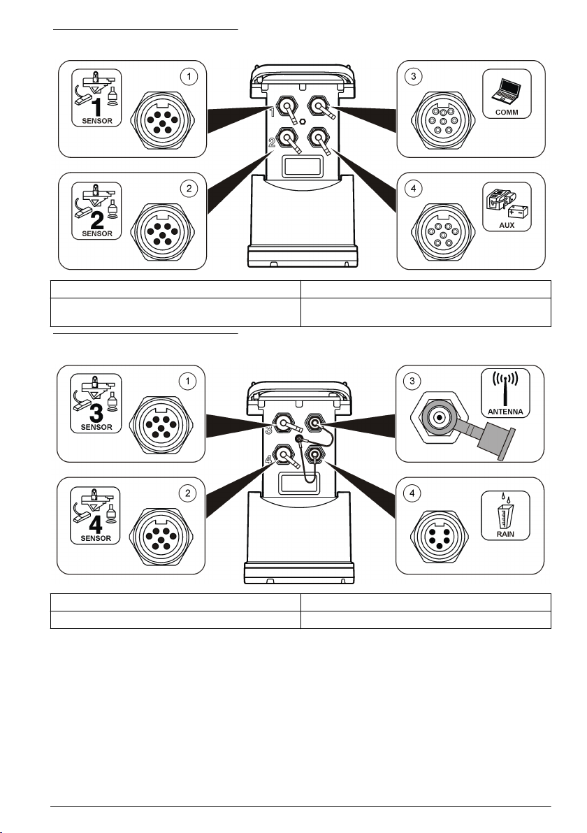
Abbildung 1 Anschlüsse – Seite 1
1 Sensor (alle Modelle) 3 Computer – USB- oder RS232-Kabel (alle Modelle)
2 Sensor (nur FL902, FL904) 4 Hilfseinrichtungen – externes Netzteil oder
Probenehmer (alle außer FL900)
Abbildung 2 Anschlüsse – Seite 2
1 Sensor (nur FL904) 3 Antennenoption (alle außer FL900)
2 Sensor (nur FL904) 4 Niederschlagsmesser (alle außer FL900)
Produktkomponenten
Stellen Sie sicher, dass Sie alle der folgenden Komponenten erhalten haben Wenn Komponenten
fehlen oder beschädigt sind, kontaktieren Sie bitte den Hersteller oder Verkäufer.
Deutsch
33
Page 34
Verbinden des Loggers mit der Stromversorgung
Einlegen der Batterien
W A R NU N G
Explosionsgefahr. Das unsachgemäße Einlegen von Batterien kann zur Freisetzung explosiver Gase
führen. Vergewissern Sie sich, dass Sie Batterien mit dem zulässigen Chemikalientyp verwenden und
dass sie mit der korrekten Polung eingelegt wurden. Verwenden Sie nicht alte und neue Batterien
zusammen.
Brandgefahr. Eine Substitution der Batterie ist unzulässig. Verwenden Sie ausschließlich
Alkalibatterien.
Ziehen Sie die Abdeckung nicht zu fest an. Ziehen Sie sie so weit an, bis die Abdeckung den O-Ring berührt.
Ziehen Sie sie dann eine viertel bis zu einer halben Umdrehung ab dem Kontakt mit dem O-Ring an. Achten Sie
darauf, dass der O-Ring jederzeit mit Silikonfett geschmiert ist.
Das Gerät kann mit zwei oder vier 6-Volt-Batterien betrieben werden. Verwenden Sie zwei Batterien
für kurzzeitige Nutzung oder vier Batterien für den langfristigen Einsatz (für Batterielebensdauer
siehe Technische Daten auf Seite 27). Wenn nur zwei Batterien verwendet werden, müssen beide
auf der gleichen Seite des Fachs eingelegt werden (A-A oder B-B). Siehe die folgenden bebilderten
Schritte.
Temperatur- und Druckänderungen können dazu führen, dass sich die Abdeckung des Batteriefachs
nur schwer von Hand entfernen lässt. In diesem Fall können Sie die Abdeckung mithilfe eines
Werkzeugs abnehmen Abbildung 3.
Abbildung 3 Entfernen der Batterieabdeckung
W A R NU N G
H I N W E I S
34 Deutsch
Page 35
1 2
3
Deutsch 35
Page 36
Anschließen eines externen Netzteils (optional)
W A R NU N G
Mögliche Explosionsgefahr. Das Gerät ist nicht für den Einsatz in explosionsgefährdeten Bereichen
zugelassen.
Das Gerät kann mit einer externen Langzeitbatterie, einem AS950 Netzteil oder einer anderen
Stromquelle betrieben werden, die Strom im angegebenen Leistungsbereich liefern kann (siehe
Technische Daten auf Seite 27 und Ersatzteile und Zubehör auf Seite 52). Falls der Logger sowohl
über ein externes Netzteil als auch über interne Batterien verfügt, werden die internen Batterien als
Hilfsstromversorgung verwendet. Wenn das externe Netzteil unter ca. 9 V fällt, liefern die internen
Batterien den Strom, bis die Spannung der externen Stromquelle wieder über 9 V steigt.
1. Installieren Sie die externe Stromquelle an einem sicheren Ort in der Nähe des Loggers.
Beachten Sie unbedingt alle Sicherheitsvorkehrungen für das Netzteil.
2. Schließen Sie das Kabel zwischen der Stromquelle und dem AUX-Anschluss des Loggers an
(Abbildung 4).
3. Führen Sie gegebenenfalls der Stromquelle Energie zu.
Abbildung 4 Externe Energieoptionen
1 Zweileiterstromkabel (Abbildung 5) 3 AS950 Netzteil
2 Netzadapterkabel 4 Langzeitbatterie
36 Deutsch
Page 37
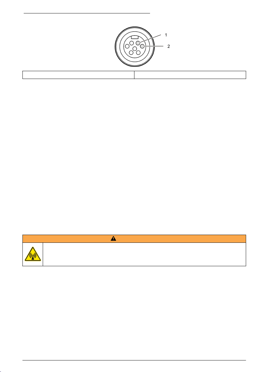
Abbildung 5 Verdrahtung des Zweileiterstromkabels
1 Strom – #16 AWG rot 2 Allgemein – #16 AWG schwarz
Inbetriebnahme
Installation von FSDATA Desktop auf dem Computer
Bevor der Durchfluss-Logger oder Probenehmer an einen Computer angeschlossen wird, ist
sicherzustellen, dass FSDATA Desktop auf dem Computer installiert ist. FSDATA Desktop steht
Ihnen unter www.hachflow.com zur Verfügung.
Anschließen des Loggers an den Computer
Voraussetzungen: Stellen Sie sicher, dass FSDATA Desktop auf dem Computer installiert ist.
Verbinden Sie nur einen Logger mit dem Computer.
1. Schließen Sie den Logger an den Computer an.
2. Wenn erstmals ein USB-Kabel angeschlossen wird, wird der Assistent für neue Hardware
geöffnet. Führen Sie den Assistenten für neue Hardware aus, um den USB-Treiber für den
Logger zu installieren. Abschließend wird die Meldung „Your new hardware is installed and ready
to use“ (Die neue Hardware wurde installiert und kann jetzt verwendet werden) angezeigt. Falls
der Assistent nicht ausgeführt wird oder die Installation fehlschlägt, wenden Sie sich an den
technischen Support, um Unterstützung bei der Fehlerbehebung für Ihr jeweiliges Betriebssystem
zu erhalten.
Anschließen eines Sensors oder externer Geräte am Logger
Voraussetzung: Stellen sie sicher, dass der Verbindungsstatus „Not connected“ (nicht verbunden)
lautet.
W A R NU N G
Gefährliche Standorte und Gefahr der HF-Strahlenbelastung durch den Sensor. Manche Sensoren
bergen die Gefahr einer HF-Strahlenbelastung und werden in explosionsgefährdeten Bereichen
verwendet. Lesen Sie die Warnungshinweise und Anweisungen im Sensorhandbuch, bevor Sie einen
Sensor an den Logger anschließen.
Die Anzahl der Sensoren, die an den Logger angeschlossen werden können, richtet sich nach dem
Modell des Loggers. Einige Sensoren müssen an ein externes Modul angeschlossen werden, das als
Schnittstelle zwischen dem Sensor und dem Logger verwendet wird. In Abbildung 7 ist das Modul
AV9000 Area Velocity Analyzer (Flächengeschwindigkeitsanalysator) an der Seite des Loggers und
die Verbindung zu einem Flächen-/Geschwindigkeitssensor dargestellt.
1. Falls das Sensorkabel an beiden Enden über Anschlüsse verfügt, schließen Sie das Kabel zuerst
an den Sensor an.
2. Schließen Sie den Sensor (oder das Modul) an einen beliebigen SENSOR-Port am Logger
(Abbildung 6 oder Abbildung 7) an. Ziehen Sie den Anschluss handfest an.
Hinweis: Für Niederschlagsmesser schließen Sie den Sensor an den RAIN-Anschluss an.
Deutsch
37
Page 38
3. Wenn der Sensor mit einem externen Modul verwendet wird, schließen Sie das Modul an den
Logger an, und schließen Sie dann den Sensor an das Modul an (Abbildung 7).
4. Falls das Sensorkabel über einen Trocknungsmittelbehälter verfügt, richten Sie den
Trocknungsmittelbehälter vertikal aus und stellen Sie sicher, dass die Luftdüse nach unten zeigt
(Abbildung 6).
Abbildung 6 Anschließen eines Sensors an den Logger
Abbildung 7 Anschließen eines Sensors an ein externes Modul
Anschließen eines externen Moduls
Zwischen einigen Sensortypen und dem Logger muss ein externes Modul als Schnittstelle verwendet
werden. Das externe Modul ist an der Seite des Loggers angebracht (Abbildung 7 auf Seite 38).
38
Deutsch
Page 39

Weitere Informationen zu Montageanweisungen entnehmen Sie der Dokumentation, die mit dem
Modul geliefert wird.
Anschließen eines Probenehmers
Der Logger kann für strömungsabhängige und Sollwert-Probenahmen an die Probenehmer
Sigma 900 Standard, Sigma 900 Max, Hach SD900 oder Hach AS950 angeschlossen werden.
Verbinden Sie mit einem AUX-Kabel den AUX-Anschluss am Logger mit dem Zusatzanschluss am
Probenehmer. Wenn es erforderlich ist, den Logger mit einer externen Stromversorgung zu
betreiben, während er an einen AS950-Probennehmer angeschlossen ist, verwenden Sie das AUXKabel für die Stromversorgung. Um ein Programm für den Probenehmer zu schreiben, konsultieren
Sie die mit dem Probenehmer mitgelieferte Dokumentation.
Benutzeroberfläche
Die Anzeigen auf der Benutzeroberfläche geben den Status des Geräts und des Modems an. Siehe
Abbildung 8 und Tabelle 3.
Abbildung 8 Benutzeroberfläche
1 Gerät ohne Modem 2 Gerät mit Modem
Tabelle 3 LED-Statusanzeigen
Anzeige LED-Farbe Beschreibung
Grün Blinkt beim normalen Betrieb alle 3 Sekunden. Blickt im Ruhemodus
Rot Blinkt, wenn ein angeschlossener Sensor nicht mit dem Logger-
Grün Bleibt während eines Anrufs an den Server konstant grün.
Rot Blinkt rot, wenn ein Anruf an den Server fehlschlägt.
alle 15 Sekunden.
Programm kommunizieren kann, wenn der erwartete Sensor nicht
gefunden wird oder der Sensorbetrieb fehlschlägt.
Programmieren eines Geräts mit einem Modem
V O R SI C H T
Gefahr von elektromagnetischer Strahlung Stellen Sie sicher, dass alle Antennen beim normalen
Gebrauch einen Mindestabstand von 20 cm (7,9 Zoll) zum Benutzer einhalten. Die Antenne darf nicht
gemeinsam mit anderen Antennen oder Sendern verwendet werden.
Deutsch 39
Page 40
Bei Geräten ohne Modem, siehe Grundlegende Einrichtung auf Seite 47. Bei Geräten mit
aktivierten Modemkonten2, siehe Hinzufügen des Loggers zum FSDATA Server auf Seite 43.
Einrichten des Wireless-Kontos
Hinweis: Für jeden Standort muss überprüft werden, ob die Netzabdeckung des ausgewählten Betreibers adäquat
ist, bevor ein Logger mit einem Mobilfunkmodem gekauft wird.
H I N W E I S
Die Sicherheit von Netzwerk und Zugangspunkt liegt in der alleinigen Verantwortung des Kunden, der das
drahtlose Gerät verwendet. Der Hersteller ist nicht haftbar für indirekte, spezielle, zufällige oder Folgeschäden,
die durch eine Verletzung der Netzwerksicherheit verursacht wurden.
Wenn der Logger mit einem Modem ausgestattet ist, können Daten vom Logger an das Internet
gesendet werden, sodass sie für den Fernzugriff zur Verfügung stehen. Hierzu muss der Benutzer
zunächst ein Konto bei einem Mobilfunkanbieter eröffnen. Daraufhin wird das Gerät beim DatenHosting-Server (FSDATA) registriert, und die anwendbaren Kommunikationseinstellungen werden
mit FSDATA Desktop im Logger programmiert. Wenn das Modem im Werk aktiviert wurde, gehen
Sie zu Hinzufügen des Loggers zum FSDATA Server auf Seite 43.
Voraussetzung: Stellen Sie sicher, dass Sie den Logger, das Logger-Testzertifikat und die Antenne
zur Hand haben.
Hinweis: Für eine optimale Fehlerbehebung installieren Sie den FSDATA Desktop-Treiber, fügen Sie den Logger
dem FSDATA-Server hinzu, und verifizieren Sie die Telemetrie, bevor Sie den Aufstellungsstandort besuchen.
1. Sammeln Sie Informationen zu Ihrem Konto.
a. Ermitteln Sie die IMEI-Nummer anhand des Etiketts. Siehe Abbildung 9.
b. Ermitteln Sie das Modemträgermodell anhand des Etiketts.
2. Wenden Sie sich an einen Mobilfunkanbieter, um das Modem in Betrieb zu nehmen. Stellen Sie
sicher, dass der WLAN-Provider mit dem Modemtyp im Logger übereinstimmt, LVW3 = Verizon
oder LAT3 = PTCRB (AT&T, T-Mobile usw.). Fordern Sie einen Datentarif mit mindestens 10 MB
Daten pro Monat und SMS an. (SMS ist optional, jedoch erforderlich, um
Alarmbenachrichtigungen an eine E-Mail-Adresse oder eine Mobiltelefonnummer zu übertragen.)
a. Teilen Sie dem Provider die IMEI-Nummer mit. Teilen Sie ihm auf Anfrage auch das
Trägermodell mit, das auf dem Senderetikett angegeben ist.
b. Notieren Sie die Telefonnummer für das Modem.
3. Verwenden Sie die Modemdiagnosefunktion in FSDATA Desktop, um den Betrieb zu verifizieren.
Siehe FSDATA Desktop-Dokumentation.
2
Geräte mit aktivierten Modemkonten verfügen über Teilenummern mit AX, .AR, .VX oder .VR am
Ende.
40 Deutsch
Page 41
Abbildung 9 Beispiele für ein Senderetikett
Einstecken einer SIM-Karte
H I N W E I S
Möglicher Geräteschaden Empfindliche interne elektronische Bauteile können durch statische
Elektrizität beschädigt werden, wobei dann das Gerät mit verminderter Leistung funktioniert oder
schließlich ganz ausfällt.
H I N W E I S
Der Geräteschrank kann beschädigt werden, wenn die Abdeckungsschrauben zu fest angezogen werden. Ziehen
Sie die Abdeckungsschrauben handfest an, mit einem maximalen Drehmoment von 2,0 Nm (20 Zoll/lb). Stellen
Sie sicher, dass die Dichtung mit Fett geschmiert wurde.
Stecken Sie eine SIM-Karte des Mobilfunkanbieters ein. Berücksichtigen Sie dabei die folgenden
bebilderten Schritte. Stellen Sie sicher, dass die PIN der SIM-Karte deaktiviert ist und die SIM-Karte
für 4G LTE-Daten gilt.
Deutsch
41
Page 42

1 2
3 4
42 Deutsch
Page 43

Anschließen einer Antenne (Wireless-Option)
V O R SI C H T
Gefahr von elektromagnetischer Strahlung Stellen Sie sicher, dass alle Antennen beim normalen
Gebrauch einen Mindestabstand von 20 cm (7,9 Zoll) zum Benutzer einhalten. Die Antenne darf nicht
gemeinsam mit anderen Antennen oder Sendern verwendet werden.
Für die drahtlose Kommunikation kann eine Antenne an das Gerät angeschlossen werden. Es ist
eine Reihe von Antennenoptionen verfügbar. Siehe Ersatzteile und Zubehör auf Seite 52.
Schließen Sie eine Antenne direkt an den Logger an, oder schließen Sie ein Antennenkabel an den
ANTENNA-Anschluss an (Abbildung 10).
Abbildung 10 Anschließen der Stab-Antenne
Hinzufügen des Loggers zum FSDATA Server
Voraussetzung: Seriennummer des Loggers
Abbildung 11 Position der Seriennummer
H I N W E I S
Achten Sie darauf, die Seriennummer und den SVC (Server-Verifizierungscode) korrekt einzugeben, um
Kommunikationsfehler zu vermeiden.
1. Gehen Sie zur Website http://fsdata.hach.com, um auf den FSDATA-Server zuzugreifen.
2. Geben Sie den Benutzernamen und das Passwort ein.
• Benutzername – der Standard-Benutzername ist die 8-stellige Kunden-ID.
• Passwort – das Standard-Passwort ist HachWebData.
Deutsch
43
Page 44

3. Gehen Sie zu Instruments>Instrument Manager (Geräte > Gerätemanager).
4. Notieren Sie den SVC (Server-Verifizierungscode) aus der linken oberen Ecke des Bildschirms:
_______________________
5. Klicken Sie auf ADD NEW (Neue hinzufügen). Das Fenster „Add Instrument“ (Gerät hinzufügen)
wird geöffnet.
6. Geben Sie die Seriennummer (SN) des Loggers ein (Abbildung 11).
7. Wählen Sie den Gerätetyp.
8. Aktivieren Sie das Kontrollkästchen „Active“ (Aktiv), und klicken Sie auf OK. Das Gerät wird im
Instrument Manager (Gerätemanager) angezeigt.
Konfiguration des Loggers zur Fernkommunikation
Voraussetzungen: Der Logger muss an den Computer angeschlossen sein. Es muss ein Konto bei
einem Netzwerkanbieter eingerichtet sein, und der Server muss konfiguriert sein.
Die Einstellungen für die Fernkommunikation müssen in FSDATA Desktop eingegeben und dann an
den Logger übertragen werden.
1. Starten Sie eine Kommunikationssitzung mit dem Logger:
a. Öffnen Sie FSDATA Desktop.
b. Klicken Sie auf CONNECT (Verbinden). Das Fenster zur Verbindung mit dem Gerät wird
geöffnet.
c. Klicken Sie auf die Schaltfläche „FL900“.
d. Wählen Sie den Port am Computer aus, an den der Logger angeschlossen ist (seriell oder
USB), und klicken Sie dann auf Connect (Verbinden).
Hinweis: Falls eine Meldung angezeigt wird, die darauf hinweist, dass der Sensor nicht übereinstimmt,
wählen Sie die Option „Create new program based on sensors connected“ (Neues Programm basierend
auf angeschlossenen Sensoren erstellen) aus.
e. Stellen Sie sicher, dass der Verbindungsstatus „Connected“ (verbunden) lautet.
2. Navigieren Sie zur Registerkarte „Communications“ (Kommunikation). Geben Sie die
Informationen für den gewünschten Standort ein. Wählen Sie die Zeitzone aus.
3. Geben Sie die Informationen für die „Remote Settings“ (Remoteeinstellungen) ein:
Option Beschreibung
Verizon 4G Es ist keine weitere Konfiguration erforderlich.
LAT3 4G Wählen Sie den Netzanbieter aus und geben Sie ggf. den
Primary Call Interval (Primäres
Anrufintervall)
Benutzernamen und das Passwort ein.
Die Häufigkeit, mit der der Logger den Server anruft.
44 Deutsch
Page 45

Option Beschreibung
Secondary Call Interval
(Sekundäres Anrufintervall)
Server Verification Code (ServerVerifizierungscode)
Die Häufigkeit, mit der der Logger den Server während einer
Alarmbedingung anruft.
Der Code, der angibt, zu welchem Konto auf dem FSDATA-Server
der Logger gehört. Der Server kann ohne diesen Code keine Daten
speichern.
4. Klicken Sie auf WRITE TO LOGGER (In Logger schreiben), um die Einstellungen zu speichern.
Ein Meldungsfenster wird angezeigt:
Optionen Beschreibung
Warning: all data will
be lost. Continue?
(Warnung: Alle Daten
gehen verloren.
Fortfahren?)
Set Logger Clock
(Logger-Uhr einstellen)
Alle Daten, die auf dem Logger gespeichert sind, werden gelöscht, wenn ein
Programm in den Logger geschrieben wird. Wählen Sie „No“ (Nein) aus, um die
Daten zu speichern und an einen sicheren Speicherort herunterzuladen. Wählen
Sie „Yes“ (Ja) aus, um alle Daten zu löschen und den Logger mit dem neuen
Programm zu aktualisieren.
„Synchronize to Computer Clock“ (Mit Computeruhr synchronisieren) – Die
Einstellungen für Datum und Uhrzeit werden aus dem Computer in den Logger
übernommen. „Set Logger Clock“ (Logger-Uhr einstellen) – Für den Logger
werden die Einstellungen für Datum und Uhrzeit verwendet, die vom Benutzer
eingestellt werden. Falls das Gerät über ein Modem verfügt, übernimmt der
Logger automatisch die Einstellungen für Datum und Uhrzeit vom Server.
Verifizieren der Telemetrie (Wireless-Option)
Der Benutzer kann manuell einen Anruf an den Server senden, um sich zu vergewissern, dass die
Netzwerkkommunikation einwandfrei ist.
1. Schließen Sie vorübergehend die Antenne an den Logger an, um die Antenne und die
Netzabdeckung am Standort vor der Installation zu testen.
2. Berühren Sie den Magnet zum Anrufinitiierungsziel (Abbildung 12). Die LED-Anzeige des
Modems wechselt zu grün.
3. Beobachten Sie die LED-Anzeige des Modems während des Anrufs (45 bis 90 Sekunden), und
warten Sie auf eine Änderung:
• LED erlischt – der Anruf an den Server war erfolgreich.
• LED blinkt rot – der Anruf an den Server ist fehlgeschlagen.
Hinweis: Wenn keine Verbindung aufgebaut werden konnte, finden Sie im BereichFehlersuche und -behebung
auf Seite 51 weitere Informationen.
Deutsch
45
Page 46

Abbildung 12 Anruf des Servers
1 Anrufinitiierungsziel 2 Magnet
Verifizieren der Telemetrie mit FSDATA Desktop
1. Wählen Sie in FSDATA Desktop „Communications“ (Kommunikation) > „Modem Diagnostics“
(Modemdiagnose) aus.
2. Vergewissern Sie sich, dass der Registrierungsstatus entweder „Home“ oder „Roaming“ ist.
Wenn nichts oder „identify“ (identifizieren) angezeigt wird, ist die Verbindung fehlgeschlagen.
3. Stellen Sie die Antenne so ein, dass Sie die optimale Signalstärke und -qualität erhalten.
4. Klicken Sie auf „Call Server“ (Server anrufen), um einen Anruf an das Netzwerk zu senden.
In einem Popup-Fenster werden Erfolg bzw. Misserfolg angezeigt.
Fehlerbehebung der Telemetrie
• Vergewissern Sie sich, dass der SVC korrekt ist.
• Vergewissern Sie sich, dass die Seriennummer auf dem Server registriert und aktiviert ist.
• Vergewissern Sie sich, dass das Modem aktiviert ist und die IP-Adresse von Hach richtig
eingegeben wurde.
• Sollten diese Maßnahmen ohne Ergebnis abgeschlossen werden, wenden Sie sich bitte an den
Technsichen Support.
Verwenden der SMS-Option
Konfigurieren Sie das FL900-Modem, um SMS-Nachrichten zu senden und zu empfangen (optional).
Angaben zu den Konfigurationsoptionen sind der FSDATA Desktop-Dokumentation zu entnehmen.
Modbus-Kommunikation
Das Modbus-Protokoll kann zur Kommunikation mit diesem Gerät verwendet werden. Schließen Sie
ein externes Netzwerkgerät (z. B. eine SPS) über die Schnittstelle am Gerät an das RS232 an, um
die geloggten Daten zu lesen.
Wenden Sie sich für weitere Informationen zur Modbus-Kommunikation an den technischen Support.
Hinweis: Legacy-Daten können nicht mithilfe von Modbus-Kommunikation gelesen werden.
46
Deutsch
Page 47

Grundlegende Einrichtung
Anhand der Informationen in dieser Bedienungsanleitung kann ein einfaches Programm für den
Logger und für die Kalibrierung des Sensors geschrieben werden. Angaben zu den erweiterten
Optionen sind der FSDATA Desktop-Dokumentation zu entnehmen. Schließen Sie die Abschnitte in
der angegebenen Reihenfolge ab.
Erstellen eines einfachen Logger-Programms
Es muss ein einfaches Programm für den Logger geschrieben werden, in dem die aufzuzeichnenden
Kanäle angegeben sind.
1. Öffnen Sie eine Kommunikationssitzung mit dem Logger:
a. Öffnen Sie FSDATA Desktop.
b. Klicken Sie auf CONNECT (Verbinden). Das Fenster zur Verbindung mit dem Gerät wird
geöffnet.
c. Klicken Sie auf die Schaltfläche „FL900“.
d. Wählen Sie den Port am Computer aus, an den der Logger angeschlossen ist (seriell oder
USB), und klicken Sie dann auf CONNECT (Verbinden).
Hinweis: Falls eine Meldung angezeigt wird, die darauf hinweist, dass der Sensor nicht übereinstimmt,
wählen Sie die Option „Create new program based on sensors connected“ (Neues Programm basierend
auf angeschlossenen Sensoren erstellen) aus.
e. Stellen Sie sicher, dass der Verbindungsstatus „Connected“ (verbunden) lautet.
2. Vervollständigen Sie die Informationen auf der Registerkarte „General Settings“ (Allgemeine
Einstellungen).
Optionen Beschreibung
Site Identification (Standort-ID) Geben Sie einen eindeutigen Namen für den Standort ein.
3. Wählen Sie die aufzuzeichnenden Kanäle im Abschnitt „Select channels to log“
(Aufzuzeichnende Datalog-Kanäle auswählen) aus:
a. Erweitern Sie die Struktur für die Logger-Kanal-Gruppe. Der Netzteil-Kanal wird immer in
dieser Gruppe angezeigt. Durch Protokollieren der Stromversorgung werden Werte für den
Ladezustand der Batterie angegeben. Für einen bestimmten Ladezustand kann ein Alarm
eingerichtet werden, um den Kontomanager über einen niedrigen Ladezustand zu
informieren, damit ein Besuch vor Ort erfolgt, um die Batterien auszuwechseln und
Datenverluste zu vermeiden. Falls der Logger einen Port für einen Niederschlagsmesser
enthält, wird der Niederschlags-Kanal ebenfalls angezeigt. Um einen Logger-Kanal in den
Datalog einzuschließen, aktivieren Sie das Kontrollkästchen neben dem Kanalnamen.
b. Erweitern Sie die Struktur für jede Port[1] (Sensor Name)-Kanalgruppe, um die verfügbaren
Kanäle für den Sensor anzuzeigen. Wenn das Kontrollkästchen neben „Logger“ oder „Port[1]“
aktiviert ist, sind automatisch alle Kanäle in der Gruppe ausgewählt.
c. Um einen Sensor-Kanal in den Datalog einzuschließen, aktivieren Sie das Kontrollkästchen
neben dem Kanalnamen. Bei jeder Auswahl eines Kanals wird die Zahl der Logger-Kanäle
erhöht.
Hinweis: Für Logger mit mehreren Sensor-Ports wird die Portnummer zum Kanalnamen hinzugefügt. So
ist beispielsweise „Geschwindigkeit 3“ der Geschwindigkeits-Kanalname für den Sensor-Port 3.
Deutsch
47
Page 48

4. So legen Sie das Protokollierungsintervall für eine Kanalgruppe fest:
a. Klicken Sie auf den Namen der Kanalgruppe, z. B. Port1 (Flo-Dar). Die
Protokollierungsintervalle werden angezeigt.
b. Wählen Sie in der Dropdown-Liste ein Intervall aus. Das primäre Protokollierungsintervall wird
für den normalen Betrieb verwendet. Das sekundäre Protokollierungsintervall wird bei
Alarmzuständen verwendet.
Hinweis: Das Protokollierungsintervall kann nicht für einen einzelnen Sensorkanal festgelegt werden.
5. Klicken Sie auf WRITE TO LOGGER (In Logger schreiben), um die Einstellungen zu speichern.
Ein Meldungsfenster wird angezeigt:
Optionen Beschreibung
Warning: all data will
be lost. Continue?
(Warnung: Alle Daten
gehen verloren.
Fortfahren?)
Set Logger Clock
(Logger-Uhr einstellen)
Alle Daten, die auf dem Logger gespeichert sind, werden gelöscht, wenn ein
Programm in den Logger geschrieben wird. Wählen Sie „No“ (Nein) aus, um die
Daten zu speichern und an einen sicheren Speicherort herunterzuladen. Wählen
Sie „Yes“ (Ja) aus, um alle Daten zu löschen und den Logger mit dem neuen
Programm zu aktualisieren.
„Synchronize to Computer Clock“ (Mit Computeruhr synchronisieren) – Die
Einstellungen für Datum und Uhrzeit werden aus dem Computer in den Logger
übernommen. „Set Logger Clock“ (Logger-Uhr einstellen) – Für den Logger
werden die Einstellungen für Datum und Uhrzeit verwendet, die vom Benutzer
eingestellt werden. Falls das Gerät über ein Modem verfügt, übernimmt der
Logger automatisch die Einstellungen für Datum und Uhrzeit vom Server.
Kalibrieren des Sensors mit dem Kalibrierungsassistenten
Voraussetzung: Der Logger muss an den Computer angeschlossen und für die Kalibrierung online
sein.
Der Sensor kann mithilfe des Kalibrierungsassistenten konfiguriert und kalibriert werden.
1. Klicken Sie auf die Registerkarte „Sensors“ (Sensoren).
2. Klicken Sie auf „Sensor Port[1]“ (Sensor-Name).
3. Klicken Sie auf die Schaltfläche CAL WIZARD (Kalibrierungsassistent). Das Fenster des
Kalibrierungsassistenten wird geöffnet.
48
Deutsch
Page 49
4. Wählen Sie auf jedem Bildschirm die gewünschten Optionen aus. Wenn der Bildschirm
„Calibration Complete“ (Kalibrierung abgeschlossen) angezeigt wird, klicken Sie auf FINISH
(Fertig stellen).
5. Klicken Sie auf WRITE TO LOGGER (In Logger schreiben), um die Einstellungen zu speichern.
Ein Meldungsfenster wird angezeigt:
Optionen Beschreibung
Warning: all data will
be lost, Continue?
(Warnung: Alle Daten
gehen verloren.
Fortfahren?)
Set Logger Clock
(Logger-Uhr einstellen)
Alle Daten, die auf dem Logger gespeichert sind, werden gelöscht, wenn ein
Programm in den Logger geschrieben wird. Wählen Sie „No“ (Nein) aus, um die
Daten zu speichern und an einen sicheren Speicherort herunterzuladen. Wählen
Sie „Yes“ (Ja) aus, um alle Daten zu löschen und den Logger mit dem neuen
Programm zu aktualisieren.
„Synchronize to Computer Clock“ (Mit Computeruhr synchronisieren) – Die
Einstellungen für Datum und Uhrzeit werden aus dem Computer in den Logger
übernommen. „Set Logger Clock“ (Logger-Uhr einstellen) – Für den Logger
werden die Einstellungen für Datum und Uhrzeit verwendet, die vom Benutzer
eingestellt werden. Falls das Gerät über ein Modem verfügt, übernimmt der
Logger automatisch die Einstellungen für Datum und Uhrzeit vom Server.
Die Installation ist abgeschlossen. Die Statusleuchte blinkt grün, wenn die Programmierung
erfolgreich war.
Installation am Standort
W A R NU N G
Mehrere Gefahren. Nur qualifiziertes Personal sollte die in diesem Kapitel des Dokuments
beschriebenen Aufgaben durchführen.
Aufhängen an einem Trägerseil
H I N W E I S
Verwenden Sie nicht die Griffe, um den Logger aufzuhängen. Die Griffe sind nicht geeignet, das Gewicht des
Loggers zu halten.
Der Logger kann für die Installation in Bereichen, wie beispielsweise einem Mannloch, an einem
Trägerseil aufgehängt werden.
1. Verbinden Sie das Trägerseil mit den Augenschrauben an der Oberseite des Loggers. Siehe
Abbildung 13.
2. Hängen Sie das Trägerseil an einem starken Haltearm wie einem optionalen Spannbalken auf.
Deutsch
49
Page 50
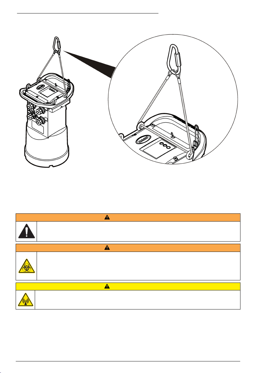
Abbildung 13 Aufhängen des Loggers an einem Trägerseil
Anbringen an der Wandhalterung
Der Logger kann an einer Wand, einem Pfosten oder einer Leiter angebracht werden. Anweisungen
sind der mit der Hardware gelieferten Dokumentation zu entnehmen.
Wartung
W A R NU N G
Mehrere Gefahren. Nur qualifiziertes Personal sollte die in diesem Kapitel des Dokuments
beschriebenen Aufgaben durchführen.
W A R NU N G
Biologische Gefährdung. Befolgen Sie die Protokolle zum sicheren Umgang, und tragen Sie alle
erforderlichen persönlichen Schutzausrüstungen beim Umgang mit einem Gerät, das möglicherweise
mit biologischen Gefahrstoffen in Kontakt gekommen ist. Dekontaminieren Sie das Gerät durch
Waschen mit einer Desinfektionsseifenlösung, und spülen Sie es mit heißem Wasser, bevor es
gewartet oder versandt wird.
Gefahr von elektromagnetischer Strahlung Stellen Sie sicher, dass alle Antennen beim normalen
Gebrauch einen Mindestabstand von 20 cm (7,9 Zoll) zum Benutzer einhalten. Die Antenne darf nicht
gemeinsam mit anderen Antennen oder Sendern verwendet werden.
Reinigung des Geräts
Reinigen Sie das Gerät außen mit einem feuchten Tuch und wischen Sie das Gerät anschließend
nach Bedarf trocken.
50
Deutsch
V O R SI C H T
Page 51

Auswechseln der Batterien
Tauschen Sie die Batterien gegen Batterien des gleichen Typs und mit identischen Kenndaten aus.
Siehe Einlegen der Batterien auf Seite 34 und Technische Daten auf Seite 27.
Auswechseln des Trocknungsmittels
Das Trocknungsmittel befindet sich im Batteriefach. Anleitungen zum Entfernen der
Batteriefachabdeckung finden Sie unter Einlegen der Batterien auf Seite 34. Das Trocknungsmittel
absorbiert Feuchtigkeit aus der Luft und verhindert die Korrosion der Geräteteile. Die
Trocknungsperlen verändern ihre Farbe, wenn sie sich mit Feuchtigkeit vollgesogen haben. Das
Trocknungsmittel muss ausgewechselt werden, wenn die Farbe der Perlen von gelb zu grün
wechselt (siehe Abbildung 14). Es ist empfehlenswert, das Trocknungsmittel gleichzeitig mit den
Batterien auszuwechseln.
Abbildung 14 Auswechseln des Trocknungsmittels
Fehlersuche und -behebung
Falls im System Probleme auftreten, sollten Sie zunächst herausfinden, ob das Problem beim
Sensor, beim Logger oder bei den Kabelverbindungen liegt.
• Prüfen Sie alle Verbindungen mit den Sensoren. Stellen Sie sicher, dass alle Verbindungen fest
sind.
• Entfernen Sie die Sensoranschlüsse, und prüfen Sie sie auf Feuchtigkeit. Reinigen und trocknen
Sie sie bei Bedarf.
• Prüfen Sie die Sensoren auf Schmutzablagerungen, und entfernen Sie diese.
• Prüfen Sie das Ereignisprotokoll auf Problemereignisse.
Kommunikationsfehler
Falls ein Anruf an den Server gesendet wurde, die Verbindung jedoch fehlgeschlagen ist, führen Sie
die folgenden Aufgaben aus:
• Trennen Sie das Gerät, und führen Sie ihm Strom zu.
• Richten Sie die Antenne aus, um die Signalstärke zu erhöhen.
• Melden Sie sich beim Server an, und stellen Sie sicher, dass die Seriennummer korrekt
eingegeben und der für die Konfiguration verwendete SVC (Server-Verifizierungscode) korrekt
aufgezeichnet wurde.
• Stellen Sie sicher, dass die Kommunikationseinstellungen im Fenster des FLO900-Treibers
korrekt eingegeben wurden.
Deutsch
51
Page 52
• Schließen Sie den Logger an den Computer an, und öffnen Sie eine Kommunikationssitzung.
Klicken Sie im Fenster des FL900-Treibers auf die Registerkarte „Diagnostics“ (Diagnose) und
dann auf das Menü „Modem“. Der Registrierungsstatus sollte „Home“ lauten.
• Falls Sie keine Lösung finden können, wenden Sie sich bitte an den technischen Support.
Ersatzteile und Zubehör
Hinweis: Produkt- und Artikelnummern können für einige Verkaufsgebiete abweichen. Wenden Sie sich an den
zuständigen Distributor oder schlagen Sie die Kontaktinformationen auf der Webseite des Unternehmens nach.
Ersatzteile
Beschreibung Artikelnr.
Batteriefachabdeckung 8524400
Batteriefachabdeckung, O-Ring 8533400
Trocknungsmittel, Kappenbaugruppe (Trocknungsmittel für Batteriefach) 8754900
Trocknungsmittelröhren-Baugruppe (Trocknungsmittel für Batteriefach) 8535200
Trocknungsmittelkügelchen (Ersatzpackung), 680 g (1,5 Pfund) 8755500
Ringschrauben, 0,6-51 x 6,5 cm (1/4–20 x 2,5 Zoll) Edelstahl 8535500
Dichtung, obere Abdeckung 8533300
Gehäuseschraube, #25,4-35,6 x 2,54 cm (10-14 x 1 Zoll) 8753300
Logger-Griff 8524200
Schmiermittel, Silikon, 7 g (0,25 Unzen) 000298HY
Magnetbaugruppe 8537800
Abdeckung und Umhängeband für den Sensor, Kommunikations- und
Zubehöranschlüsse
Abdeckung und Umhängeband für Niederschlagsmesser-Anschluss 9492500
8535000
Power (Ein/Aus)
Beschreibung Artikelnr.
Batterie, 6 V, (Laternenbatterie) 11013M
Alkalibatterie, Langzeit 8542900
Langzeit-Alkali-Akku, obere Abdeckung, Adapter und Kabel 8543000
Kabelbaugruppe, externe Stromversorgung, 2,7 m (9 Fuß) 8528700
Kabelbaugruppe, externe Stromversorgung, 7,6 m (25 Fuß) 8528701
Befestigungsmaterial
Beschreibung Artikelnr.
Wandhalterung ohne Leiter-Abhängungs-Kit 8542700
Wandmontagehalterungs-Adapter 8543800
52 Deutsch
Page 53

Antennen
Beschreibung Artikelnr.
Stab-Antenne, 3G/4G LTE, 3 dBi 8623800
Miniwing, 2G/3G/4G LTE, 2,5 m (8,2 Fuß) Kabel, 5,5 dBi 8624000
Bodenverlegung, 3G/4G LTE, 3 m (9,8 Fuß) Kabel, 3 dBi 8624200
Schachtabdeckung, 3G/4G LTE, 3 m (9,8 Fuß) Kabel, 3 dBi 8624400
Hilfs-/Probenehmerkabel
Beschreibung Artikelnr.
AUX-Kabel, Mehrzweckkabel (einseitig offen), 7-polig, 2,7 m (9 Fuß) 8528500
AUX-Kabel, Mehrzweckkabel (einseitig offen), 7-polig, 7,6 m (25 Fuß) 8528501
Kabel, FL900 Logger an AS950 AUX-Anschluss, 7-polig, 2,7 m (9 Fuß) 9500700
Kabel, FL900 Logger an AS950 AUX-Anschluss, 7-polig, 7,6 m (25 Fuß) 9500701
Kabelbaugruppe, Stromversorgungseingang AUX, AS950-FL900 mit Netzadapter 8322800
Deutsch 53
Page 54
Sommario
Specifiche tecniche a pagina 54 Configurazione di base a pagina 72
Informazioni generali a pagina 55 Installazione nel sito a pagina 74
Alimentazione del logger a pagina 61 Manutenzione a pagina 75
Avvio del sistema a pagina 64 Individuazione ed eliminazione dei guasti
Programmazione di un'unità dotata di modem
a pagina 66
Comunicazione Modbus a pagina 72
a pagina 76
Parti di ricambio e accessori a pagina 77
Ulteriori informazioni
Ulteriori informazioni sono disponibili sul sito Web del produttore.
Specifiche tecniche
Le specifiche tecniche sono soggette a modifica senza preavviso.
Dato tecnico Dettagli
Dimensioni (L x P x A) 25,4 x 22 x 40 cm (10,0 x 8,7 x 16,0 pollici)
Alloggiamento Schiuma strutturale PC/ABS
Classificazione ambientale NEMA 6P/IP68 (immersione per 24 ore a 1,8 m (6 piedi))
Peso (modello FL900) 4,5 kg (10 lb) senza batterie, 6,3 kg (14 lb) con 2 batterie e 8,2 kg (18 lb) con
Temperatura di funzionamento Da –18 a 60 ºC (da 0 a 140 ºF) al 95% di umidità relativa
Temperatura di stoccaggio Da –40 a 60 ºC (da –40 a 140 ºF)
Requisiti di alimentazione Da 8 a 18 Vcc tramite batterie o fonte di alimentazione esterna, 2,5 W max.
Durata della batteria Varia in base al tipo di sensore, agli intervalli di registrazione, alla telemetria e
Categoria di installazione I
Classe di protezione III
Grado di inquinamento 4
Porte per i sensori 1, 2 o 4 porte
Connettori Connettori in acciaio inox
Canali registro dati Fino a 16
Allarmi Fino a 16 allarmi dei canali con opzioni alto/alto, alto, basso, basso/basso. Gli
4 batterie
all'ambiente.
Per un intervallo di registrazione di 15 minuti, senza modem, quattro batterie
rettangolari da 6 V a temperatura ambiente:
• Sensore Flo-tote 3 306 giorni
• Sensore Area/Velocità con Analyzer AV9000 296 giorni
• Sensore Flo-Dar 185 giorni
• Sensore ultrasonico 456 giorni
Nota: per usi prolungati utilizzare con batteria a lunga durata, PN 8542900.
allarmi di sistema includono livello basso della batteria, livello basso della
batteria RTC, memoria slate insufficiente, memoria slate piena, timeout
sensore, ID sensore.
54 Italiano
Page 55

Dato tecnico Dettagli
Azioni allarmi Avvio del campionatore, modifica degli intervalli di registrazione, invio di e-mail
Intervalli di registrazione 1, 2, 3, 4, 5, 6, 10, 12, 15, 20, 30 o 60 minuti
Archivio dati Registro eventi: fino a 1000 eventi in memoria flash non volatile
Comunicazione PC USB
Comunicazione remota
(opzionale)
Protocolli Modbus RTU (RS232)
Precisione del time base ±0,002%, sincronizzato ogni 24 ore con il software del server e il modem
Sensori supportati Flo-Dar, Flo-Dar con SVS, Flo-Tote, pluviometro, Ultrasonico, Area sommersa
Interfaccia campionatore Compatibile con Sigma 900 Standard, Sigma 900 Max, Hach SD900 e
Certificazioni Logger: CE
Garanzia 1 anno
o SMS da logger o server.
Nota: Possono essere applicate le normali tariffe per gli SMS. Non tutti i tipi di allarme
possono essere disponibili con tutti i gestori telefonici e piani di servizi.
Intervalli primari e secondari per registrazione dinamica
Cronologia campionamento: fino a 2000 eventi campione in memoria flash non
volatile
Registro dati: 325.000 punti dati, 1128 giorni per 3 canali a intervalli di
registrazione di 15 minuti
RS232 (velocità: 9600, 19200, 38400, 57600, 115200 baud)
Modem wireless: 3G, 4G LTE (Verizon); 3G, 4G LTE, PTCRB (USA e Canada)
Mobile-Terminated SMS
Mobile-Originated SMS
Velocità1, Sigma 950
AS950 per il supporto di campionamento con valore di riferimento (set point),
campionamento a flusso e registrazione cronologia campionamento
Alimentatore CA opzionale: standard UL/CSA (cETLus)/CE
Modem: FCC, IC (altri eventualmente disponibili; per ulteriori informazioni
contattare il produttore).
1
Informazioni generali
In nessun caso, il produttore potrà essere ritenuto responsabile per danni diretti, indiretti o accidentali
per qualsiasi difetto o omissione relativa al presente manuale. Il produttore si riserva il diritto di
apportare eventuali modifiche al presente manuale e ai prodotti ivi descritti in qualsiasi momento
senza alcuna notifica o obbligo preventivi. Le edizioni riviste sono presenti nel sito Web del
produttore.
Informazioni sulla sicurezza
A V V I S O
Il produttore non sarà da ritenersi responsabile in caso di danni causati dall'applicazione errata o dall'uso errato di
questo prodotto inclusi, a puro titolo esemplificativo e non limitativo, i danni incidentali e consequenziali; inoltre
declina qualsiasi responsabilità per tali danni entro i limiti previsti dalle leggi vigenti. La responsabilità relativa
all'identificazione dei rischi critici dell'applicazione e all'installazione di meccanismi appropriati per proteggere le
attività in caso di eventuale malfunzionamento dell'apparecchiatura compete unicamente all'utilizzatore.
1
Questo dispositivo si collega mediante un modulo esterno.
Italiano 55
Page 56
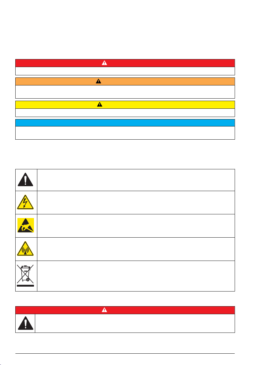
Prima di disimballare, installare o utilizzare l’apparecchio, si prega di leggere l’intero manuale. Si
raccomanda di leggere con attenzione e rispettare le istruzioni riguardanti note di pericolosità. La non
osservanza di tali indicazioni potrebbe comportare lesioni gravi all'operatore o danni all'apparecchio.
Assicurarsi che i dispositivi di sicurezza insiti nell'apparecchio siano efficaci all'atto della messa in
servizio e durante l'utilizzo dello stesso. Non utilizzare o installare questa apparecchiatura in modo
diverso da quanto specificato nel presente manuale.
Indicazioni e significato dei segnali di pericolo
P E R IC O L O
Indica una situazione di pericolo potenziale o imminente che, se non evitata, causa lesioni gravi anche mortali.
A V V ER T E N Z A
Indica una situazione di pericolo potenziale o imminente che, se non evitata, potrebbe comportare lesioni gravi,
anche mortali.
A T T EN ZI O N E
Indica una situazione di pericolo potenziale che potrebbe comportare lesioni lievi o moderate.
Indica una situazione che, se non evitata, può danneggiare lo strumento. Informazioni che richiedono particolare
attenzione da parte dell'utente.
A V V I S O
Etichette di avvertimento
Leggere tutte le etichette presenti sullo strumento. La mancata osservanza delle stesse può causare
lesioni personali o danni allo strumento. Un simbolo sullo strumento è indicato nel manuale
unitamente a una frase di avvertenza.
Questo è il simbolo di allarme sicurezza. Seguire tutti i messaggi di sicurezza dopo questo simbolo
per evitare potenziali lesioni. Se sullo strumento, fare riferimento al manuale delle istruzioni per il
funzionamento e/o informazioni sulla sicurezza.
Questo simbolo indica un rischio di scosse elettriche e/o elettrocuzione.
Questo simbolo indica la presenza di dispositivi sensibili alle scariche elettrostatiche (ESD, Electrostatic Discharge) ed è pertanto necessario prestare la massima attenzione per non danneggiare
l'apparecchiatura.
Questo simbolo indica onde radio.
Le apparecchiature elettriche contrassegnate con questo simbolo non possono essere smaltite
attraverso sistemi domestici o pubblici europei. Restituire le vecchie apparecchiature al produttore il
quale si occuperà gratuitamente del loro smaltimento.
Misure di sicurezza negli spazi confinati
P E R IC O L O
Pericolo di esplosione. La formazione per i test di pre-immissione, le procedure di ventilazione, di
immissione e di evacuazione/salvataggio e le pratiche per il lavoro sicuro sono necessarie prima di
accedere a spazi ristretti.
Le informazioni riportate di seguito intendono aiutare gli utenti a comprendere i pericoli e i rischi
associati all'ingresso in spazi confinati.
56
Italiano
Page 57

Il 15 aprile 1993, la normativa finale di OSHA (Agenzia europea per la sicurezza e la salute sul
lavoro) contrassegnata dal n. 1910.146, “Permit Required Confined Spaces”, è divenuta legge.
Questa normativa influisce direttamente su 250.000 siti industriali negli Stati Uniti ed è stata emanata
per salvaguardare la salute e la sicurezza dei lavoratori in spazi confinati.
Definizione di spazio confinato:
Con spazio confinato s'intende qualsiasi luogo o area chiusa che presenti, o abbia l'immediato
potenziale di presentare, una o più delle seguenti condizioni:
• Atmosfera con una concentrazione di ossigeno inferiore al 19,5% o superiore al 23,5% e/o una
concentrazione di idrogeno solforato (H2S) superiore a 10 ppm.
• Atmosfera potenzialmente infiammabile o esplosiva a causa di gas, vapori, nebbie, polveri o fibre.
• Materiali tossici che tramite contatto o inalazione potrebbero causare lesioni, problemi di salute o
morte.
Gli spazi confinati non sono destinati per essere utilizzati da persone. L'ingresso agli spazi confinati è
riservato e tali aree contengono pericoli noti o potenziali. Esempi di spazi confinati includono chiusini,
ciminiere, tubi, fosse, sotterranei, e altri aree simili.
Le procedure di sicurezza standard devono sempre essere ottemperate prima di accedere agli spazi
confinati e/o le aree in cui possono essere presenti gas, vapori, nebbie, polveri o fibre pericolosi.
Prima di entrare in uno spazio confinato, leggere tutte le procedure correlate a questa attività.
Certificazioni
Canadian Radio Interference-Causing Equipment Regulation, IECS-003, Class A:
Le registrazioni dei test di supporto sono disponibili presso il produttore.
Il presente apparato digitale di Classe A soddisfa tutti i requisiti dello standard canadese Canadian
Interference-Causing Equipment Regulations: CAN ICES-3(A)/NMB-3(A)".
Questo apparecchio digitale di Classe A soddisfa tutti i requisiti di cui agli Ordinamenti canadesi sulle
apparecchiature causanti interferenze.
FCC Parte 15, Limiti Classe "A"
Le registrazioni dei testi di supporto sono disponibili presso il produttore. Il presente dispositivo è
conforme alla Parte 15 della normativa FCC. Il funzionamento è subordinato alle seguenti condizioni:
1. L'apparecchio potrebbe non causare interferenze dannose.
2. L'apparecchio deve tollerare tutte le interferenze subite, comprese quelle causate da
funzionamenti inopportuni.
Modifiche o cambiamenti eseguiti sull’unità senza previa approvazione da parte dell'ente
responsabile della conformità potrebbero annullare il diritto di utilizzare l'apparecchio. Questo
apparecchio è stato testato ed è conforme con i limiti per un dispositivo digitale di Classe A, secondo
la Parte 15 delle normative FCC. I suddetti limiti sono stati fissati in modo da garantire una
protezione adeguata nei confronti di interferenze nocive se si utilizza l’apparecchiatura in applicazioni
commerciali. L’apparecchiatura produce, utilizza e può irradiare energia a radiofrequenza e, se non
installata e utilizzata in accordo a quanto riportato nel manuale delle istruzioni, potrebbe causare
interferenze nocive per le radiocomunicazioni. L'utilizzo di questa apparecchiatura in una zona
residenziale può provocare interferenze dannose; in tal caso, l'utente dovrà eliminare l'interferenza a
proprie spese. Per ridurre i problemi di interferenza, è possibile utilizzare le seguenti tecniche:
1. Scollegare l'apparecchio dalla sua fonte di potenza per verificare che sia la fonte dell’interferenza
o meno.
2. Se l'apparecchio è collegato alla stessa uscita del dispositivo in cui si verifica l'interferenza,
collegare l'apparecchio ad un'uscita differente.
3. Spostare l'apparecchio lontano dal dispositivo che riceve l'interferenza.
4. Posizionare nuovamente l’antenna di ricezione dell’apparecchio che riceve le interferenze.
5. Provare una combinazione dei suggerimenti sopra riportati.
Italiano
57
Page 58

Certificazione modem wireless
Il dispositivo è conforme alla Parte 15 della normativa sugli standard RSS dell'industria canadese e
FCC per l'esenzione di licenza (FCC and Industry Canada licence-exempt RSS standard(s) Rules). Il
funzionamento è subordinato alle seguenti condizioni:
1. L'apparecchio potrebbe non causare interferenze dannose.
2. L'apparecchio deve tollerare tutte le interferenze subite, comprese quelle causate da
funzionamenti inopportuni.
Modifiche o cambiamenti eseguiti sull’unità di comunicazione wireless senza previa approvazione da
parte dell'ente responsabile della conformità potrebbero annullare il diritto di utilizzare l'apparecchio.
Qualsiasi modifica allo strumento annullerà la certificazione Industry Canada e concessione FCC.
Sono incluse le modifiche ai modem wireless e alle antenne associate, inclusi i cavi delle antenne.
Attenersi alle raccomandazioni del produttore per l'installazione, la configurazione e il funzionamento
wireless del prodotto.
Dispositivi cellulari
A V V I S O
La responsabilità per la sicurezza della rete e dei punti di accesso è del cliente che utilizza lo strumento wireless.
Il produttore non può essere ritenuto responsabile di danni indiretti, speciali, incidentali o consequenziali causati
da una violazione della sicurezza della rete.
A V V ER T E N Z A
Precauzioni per portatori di pacemaker. Le interferenze elettromagnetiche (EMI) possono:
• Interrompere gli impulsi provenienti dal pacemaker che controllano il ritmo cardiaco.
• Provocare impulsi irregolari da parte del pacemaker.
• Causare l'invio di impulsi preimpostati da parte del pacemaker che allo stesso tempo ignorerà il
ritmo cardiaco.
Recenti ricerche hanno dimostrato che i dispositivi cellulari non rappresentano un significativo rischio
per la salute per la maggior parte dei portatori di pacemaker. Tuttavia, i portatori di pacemaker
dovrebbero prendere precauzioni per essere certi che il proprio dispositivo non causi problemi.
Mantenere il dispositivo a una distanza minima di 20 cm (7,9 pollici) dal corpo.
A T T EN ZI O N E
Pericolo di radiazioni elettromagnetiche. Assicurarsi che l'antenna si trovi a una distanza minima di
20 cm (7,9 pollici) da tutto il personale durante le normali operazioni. L'antenna non può essere
collocata nella stessa posizione o utilizzata insieme ad altre antenne o trasmettitori.
A T T EN ZI O N E
Pericolo di radiazioni elettromagnetiche. Nelle applicazioni portatili, mantenere il modem a una distanza
non inferiore a 20 cm (7,9 pollici) dal corpo.
Approvazioni normative dispositivi RF
Modem MTSMC-LAT3 (classe apparecchiatura: PCS Licensed Transmitter, modulo LTE/3G):
• FCC: approvato come dispositivo modulare in virtù di una concessione TCB di autorizzazione.
FCC ID: RI7LE910NAV2
• IC: approvato come dispositivo modulare in virtù di un certificato di conformità tecnica C-REL ID:
5131A-LE910NAV2
Modem MTSMC-LVW3 (PCS Licensed Transmitter, modulo LTE/3G):
• FCC: approvato come dispositivo modulare in virtù di una concessione TCB di autorizzazione.
FCC ID: RI7LE910SVV2
• IC: approvato come dispositivo modulare in virtù di un certificato di conformità tecnica C-REL ID:
5131A-LE910SVV2
58
Italiano
Page 59

Tabella 1 Modem cellulare: MTSMC-lat3
Parti delle normative FCC Bande di frequenza (MHz) Massima potenza in uscita (Watt)
22, 24, 27 700 (B12/B13), 850 (B5), 1700 (B4),
1900 (B2)
0,232
Modem cellulare MTSMC-LAT3 - Note e condizioni per la concessione FCC:
Approvazione modulare singola. L'uscita di potenza elencata è di tipo condotta. Questo dispositivo è
approvato per l'uso mobile e fisso rispetto alla conformità all'esposizione RF e può essere
commercializzato solo agli installatori OEM. Le antenne utilizzate per questo trasmettitore, come
descritto nel presente documento, devono essere installate in modo da trovarsi a una distanza di
almeno 20 cm dalle persone. Gli installatori e gli utenti finali devono essere provvisti delle condizioni
operative per soddisfare la conformità all'esposizione RF. Guadagno antenna/perdita cavo massimo
consentito: 6,63 dBi per 700 MHz e 850 MHz; 6,00 dBi per 1700 MHz; 8,51 dBi per 1900 MHz.
Tabella 2 Modem cellulare: MTSMC-LVW3
Parti delle normative FCC Bande di frequenza (MHz) Massima potenza in uscita (Watt)
24, 27 700 (B13), 1700 (B4), 1900 (B2) 0,219
Modem cellulare MTSMC-LVW3 - Note e condizioni per la concessione FCC:
Approvazione modulare singola. L'uscita di potenza elencata è di tipo condotta. Questo dispositivo è
approvato per l'uso mobile e fisso rispetto alla conformità all'esposizione RF e può essere
commercializzato solo agli installatori OEM. Le antenne utilizzate per questo trasmettitore, come
descritto nel presente documento, devono essere installate in modo da trovarsi a una distanza di
almeno 20 cm dalle persone. Gli installatori e gli utenti finali devono essere provvisti delle condizioni
operative per soddisfare la conformità all'esposizione RF. Guadagno antenna/perdita cavo massimo
consentito: 6,94 dBi per 700 MHz; 6,00 dBi per 1700 MHz; 9,01 dBi per 1900 MHz.
Panoramica del prodotto
I logger di portata serie FL900 vengono impiegati in studi di monitoraggio della portata di canali
aperti, ad esempio afflusso e infiltrazione, acque di sfioro da fognatura mista, capacità e
pianificazione e monitoraggio del deflusso.
I dati vengono raccolti dai sensori collegati e registrati in un archivio. I sensori possono essere
aggiunti e sostituiti sul campo. In base al modello, è possibile collegare fino a quattro sensori. I dati
possono essere recuperati direttamente tramite un cavo USB o RS232 o a distanza attraverso una
rete wireless utilizzando FSDATA Desktop e il software server FSDATA. I logger serie
FL900 possono essere collegati a una fonte di alimentazione esterna, un pluviometro o impiegati con
un campionatore Sigma o Hach.
La funzionalità wireless e il numero di connettori disponibili variano a seconda del modello di logger.
Fare riferimento a Figura 1 e a Figura 2.
Italiano
59
Page 60

Figura 1 Connettori—lato 1
1 Sensori (tutti i modelli) 3 Computer—Cavo USB o RS232 (tutti i modelli)
2 Sensore (solo FL902 e FL904) 4 AUX—Alimentatore esterno o campionatore (tutti i
modelli eccetto FL900)
Figura 2 Connettori—lato 2
1 Sensore (solo FL904) 3 Antenna opzionale (tutti i modelli eccetto FL900)
2 Sensore (solo FL904) 4 Pluviometro (tutti i modelli eccetto FL900)
Componenti del prodotto
In mancanza di un componente o in presenza di eventuali danni, contattare immediatamente il
produttore o il rappresentante.
60
Italiano
Page 61

Alimentazione del logger
Installazione delle batterie
A V V ER T E N Z A
Pericolo di esplosione. L'errata installazione della batteria può causare il rilascio di gas esplosivi.
Accertarsi che le batterie siano dello stesso tipo chimico approvato e che siano inserite
nell'orientamento corretto. Non mettere insieme batterie nuove con batterie vecchie.
A V V ER T E N Z A
Pericolo di incendio. È vietato utilizzare batterie non originali. Utilizzare esclusivamente batterie
alcaline.
Non serrare eccessivamente il coperchio. Stringere finché il coperchio non tocca l'anello di tenuta, quindi
stringere di un quarto di giro o mezzo giro al massimo dal contatto dell'anello di tenuta. Lubrificare l'anello di
tenuta con un grasso al silicone.
Lo strumento è alimentato con due o quattro batterie da 6 V. Si consiglia di inserire due batterie per
un utilizzo di breve durata e quattro batterie per un utilizzo a lungo termine (per la durata delle
batterie, consultare la sezione Specifiche tecniche a pagina 54). Nel caso in cui si utilizzino solo due
batterie, inserirle entrambe nello stesso lato del vano (A-A o B-B). Fare riferimento ai punti illustrati di
seguito.
Variazioni di temperatura e pressione possono rendere difficoltosa la rimozione manuale del
coperchio del vano batterie. In tal caso, usare un attrezzo per rimuovere il coperchio (Figura 3).
Figura 3 Rimozione del coperchio del vano batterie
A V V I S O
Italiano 61
Page 62

1 2
3
62 Italiano
Page 63

Collegamento di un alimentatore esterno (opzionale)
A V V ER T E N Z A
Potenziale pericolo di esplosione. Lo strumento non è approvato per l'uso in aree pericolose.
Lo strumento può essere alimentato mediante una batteria esterna a lunga durata, un alimentatore
AS950 o un'altra fonte in grado di fornire un'alimentazione compresa nel range specificato
(consultare Specifiche tecniche a pagina 54 e Parti di ricambio e accessori a pagina 77). Se il
logger è dotato sia di alimentazione esterna che di batterie interne, queste ultime vengono utilizzate
come alimentazione ausiliaria. Quando la tensione dell'alimentatore esterno scende sotto circa 9 V,
le batterie interne forniscono l'alimentazione necessaria fino a quando la tensione della fonte esterna
non sale nuovamente sopra i 9 V.
1. Installare la fonte di alimentazione esterna in un luogo sicuro vicino al logger. Rispettare tutte le
norme di sicurezza valide per gli alimentatori.
2. Collegare il cavo dall'alimentatore al connettore AUX del logger (Figura 4).
3. Se necessario, fornire corrente all'alimentatore.
Figura 4 Alimentatori esterni disponibili
1 Cavo di alimentazione a 2 conduttori (Figura 5) 3 Alimentatore AS950
2 Cavo per trasformatore 4 Batteria a lunga durata
Italiano 63
Page 64
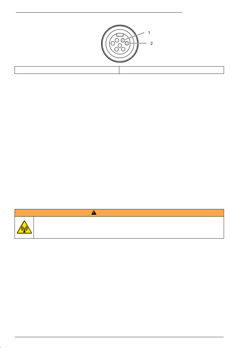
Figura 5 Schema di collegamento del cavo di alimentazione a 2 conduttori
1 Power—AWG 16 rosso 2 Common—AWG 16 nero
Avvio del sistema
Installazione di FSDATA Desktop su un computer
Prima di collegare il logger di portata o il campionatore a un computer, assicurarsi che su
quest'ultimo sia installato FSDATA Desktop. FSDATA Desktop è disponibile presso
www.hachflow.com.
Collegamento del logger a un computer
Prerequisiti: verificare che FSDATA Desktop sia installato sul computer.
Collegare al computer un solo logger.
1. Collegare il logger al computer.
2. Quando si collega per la prima volta un cavo USB, viene visualizzata la procedura Installazione
guidata nuovo hardware. Eseguire la procedura guidata per installare il driver USB del logger. Al
termine, viene visualizzato il messaggio: "Your new hardware is installed and ready to use" (Il
nuovo hardware è installato e pronto per l'uso). Se la procedura guidata non viene eseguita o se
l'installazione non riesce, contattare il supporto tecnico per richiedere assistenza nella risoluzione
dei problemi del sistema operativo specifico.
Collegamento di un sensore o di un dispositivo esterno al logger
Prerequisito: accertarsi che lo stato di connessione sia "not connected" non collegato.
A V V ER T E N Z A
Aree pericolose e pericolo di esposizione alle radiofrequente (RF) per i sensori. Alcuni sensori
presentano un pericolo di esposizione alle radiofrequenze se utilizzati in atmosfere esplosive. Prima di
collegare un sensore al logger, consultare le avvertenze e le istruzioni contenute nel manuale del
sensore.
Il numero di sensori che è possibile collegare al logger varia in base al modello dell'unità. Alcuni
sensori devono essere collegati a un modulo esterno che viene utilizzato come interfaccia tra il
sensore e il logger. Figura 7 mostra il modulo AV9000 Area Velocity Analyzer a lato del logger e la
connessione a un sensore di velocità/area sommersa.
1. Se il cavo del sensore è provvisto di un connettore a entrambe le estremità, collegare prima il
cavo al sensore.
2. Collegare il sensore (o il modulo) a una delle porte SENSOR del logger (Figura 6 o Figura 7).
Serrare il connettore manualmente.
Nota: Se si tratta di un pluviometro, collegare il sensore al connettore RAIN.
3. Se il sensore utilizza un modulo esterno, collegarlo al logger, quindi collegare il sensore al
modulo (Figura 7).
4. Se il cavo del sensore dispone di un contenitore dell'essiccante, allinearlo verticalmente e
assicurarsi che il foro dell'aria sia rivolto verso il basso (Figura 6).
64
Italiano
Page 65

Figura 6 Collegamento di un sensore al logger
Figura 7 Collegamento di un sensore a un modulo esterno
Collegamento di un modulo esterno
Il modulo esterno deve essere utilizzato come interfaccia tra alcuni tipi di sensori e il logger. Il
modulo esterno è montato a lato del logger (Figura 7 a pagina 65). Per le istruzioni di montaggio,
consultare la documentazione fornita insieme al modulo.
Aggiunta a un campionatore
Il logger può essere aggiunto a un campionatore Sigma 900 Standard, Sigma 900 Max, Hach
SD900 o Hach AS950 per eseguire campionamenti a flusso e con un valore di riferimento (set point).
Italiano
65
Page 66
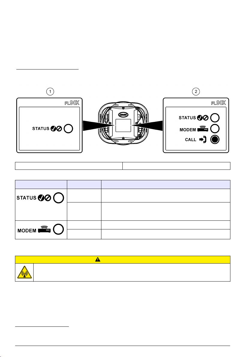
Collegare la porta AUX del logger alla porta ausiliaria presente sul campionatore utilizzando un cavo
ausiliario completo. Se è necessario alimentare esternamente il logger mentre è collegato a un
campionatore AS950, utilizzare il gruppo cavo ausiliario di ingresso alimentazione. Per creare un
programma di campionamento, consultare la documentazione allegata al campionatore.
Interfaccia utente
Gli indicatori sull'interfaccia utente mostrano lo stato dello strumento e del modem. Fare riferimento a
Figura 8 e Tabella 3.
Figura 8 Interfaccia utente
1 Strumento senza modem 2 Strumento con modem
Tabella 3 Indicatori di stato LED
Indicatore Colore del LED Descrizione
Verde Lampeggia ogni 3 secondi durante il normale funzionamento.
Rosso Lampeggia se il sensore collegato non è compatibile con il
Verde Resta verde fisso durante una chiamata al server.
Rosso Lampeggia in rosso se la chiamata non ha raggiunto il server.
Lampeggia ogni 15 secondi in modalità di sospensione.
programma del logger, se il sensore previsto non è stato trovato o
se il sensore non funziona.
Programmazione di un'unità dotata di modem
A T T EN ZI O N E
Pericolo di radiazioni elettromagnetiche. Assicurarsi che l'antenna si trovi a una distanza minima di
20 cm (7,9 pollici) da tutto il personale durante le normali operazioni. L'antenna non può essere
collocata nella stessa posizione o utilizzata insieme ad altre antenne o trasmettitori.
Per le unità senza modem, consultare Configurazione di base a pagina 72. Per le unità fornite con
account modem attivati2, passare a Collegamento del logger al server FSDATA a pagina 70.
Impostazione di un account wireless
Nota: È necessario verificare che il gestore selezionato fornisca un'adeguata copertura cellulare di ogni sito prima
di acquistare un logger con un modem cellulare.
2
Le unità fornite con account modem attivati dispongono di numeri di parte le cui lettere finali
sono .AX, .AR, .VX o .VR.
66 Italiano
Page 67

A V V I S O
La sicurezza dei punti di accesso e della rete è esclusiva responsabilità del cliente che utilizza lo strumento
wireless. Il produttore non può essere ritenuto responsabile di danni indiretti, speciali, incidentali o consequenziali
causati da una violazione della sicurezza della rete.
Se il logger dispone di un modem, è possibile inviare dati dal logger su Internet e accedervi in
remoto. L'utente deve innanzi tutto aprire un account con un provider di servizi mobili (wireless). Lo
strumento viene quindi registrato sul server dati di hosting (FSDATA) e le impostazioni di
comunicazione necessarie vengono configurate nel logger utilizzando FSDATA Desktop. Se il
modem è stato attivato in fabbrica, consultare Collegamento del logger al server FSDATA
a pagina 70.
Prerequisito: accertarsi che il logger, il certificato di verifica del logger e l'antenna siano nelle
vicinanze.
Nota: Per l'individuazione e l'eliminazione ottimale dei guasti, installare il driver FSDATA Desktop, collegare il
logger al server FSDATA, quindi verificare la telemetria prima di visitare il sito di implementazione.
1. Prendere nota delle informazioni sull'account.
a. Individuare il numero IMEI sull'etichetta. Fare riferimento a Figura 9.
b. Individuare il modello di portante del modem sull'etichetta.
2. Contattare un provider per attivare il servizio sul modem. Assicurarsi che il provider di servizi
wireless corrisponda al tipo di modem presente nel logger, LVW3 = Verizon o LAT3 = PTCRB
(AT&T, T-Mobile, ecc.). Richiedere un piano dati con un minimo di 10 MB di dati al mese e
servizio SMS. Il servizio SMS è opzionale ma necessario per trasmettere le notifiche di allarme a
un indirizzo e-mail o a un numero di cellulare.
a. Fornire al provider il numero IMEI. Se richiesto, specificare il modello di vettore, anch'esso
indicato sull'etichetta del trasmettitore.
b. Registrare il numero di telefono per il modem.
3. Utilizzare la diagnostica del modem in FSDATA Desktop per verificare il funzionamento. Fare
riferimento alla documentazione di FSDATA Desktop.
Figura 9 Esempi di etichetta del trasmettitore
Italiano 67
Page 68
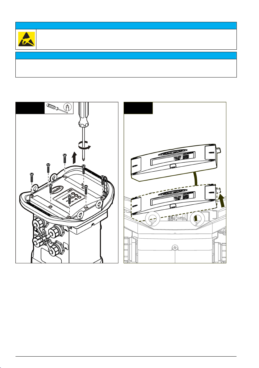
Installare una scheda SIM
A V V I S O
Danno potenziale allo strumento. Componenti elettronici interni delicati possono essere danneggiati
dall'elettricità statica, compromettendo le prestazioni o provocando guasti.
A V V I S O
L'involucro esterno dello strumento può rompersi se le viti del coperchio vengono serrate eccessivamente.
Stringere le viti del coperchio a mano applicando una coppia massima di 2,0 Nm (20 pollici/libbre). Lubrificare la
guarnizione con grasso.
Installare una scheda SIM fornita dal gestore di telefonia mobile. Fare riferimento ai passaggi
illustrati di seguito. Assicurarsi che il PIN della scheda SIM sia disabilitato e che la scheda SIM
supporti i dati 4G LTE.
1 2
68 Italiano
Page 69
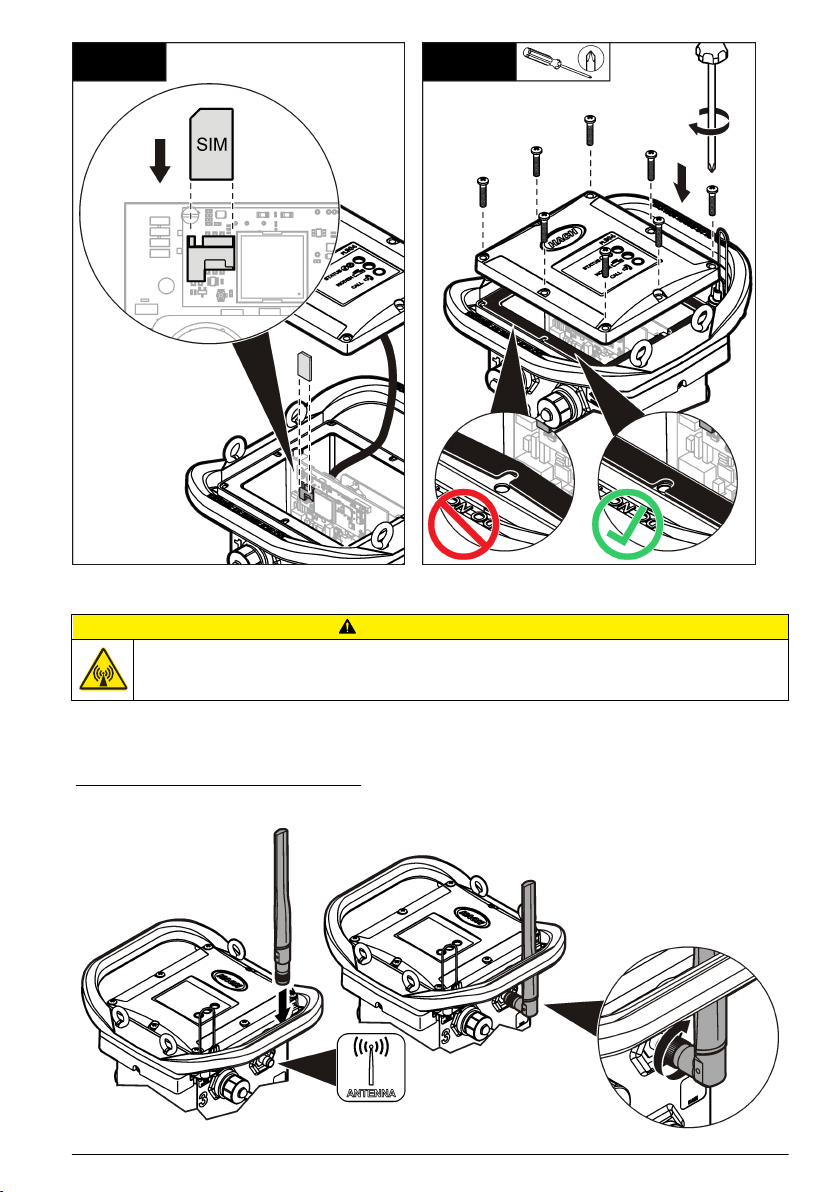
3 4
Collegamento di un'antenna
A T T EN ZI O N E
Pericolo di radiazioni elettromagnetiche. Assicurarsi che l'antenna si trovi a una distanza minima di
20 cm (7,9 pollici) da tutto il personale durante le normali operazioni. L'antenna non può essere
collocata nella stessa posizione o utilizzata insieme ad altre antenne o trasmettitori.
È possibile collegare allo strumento un'antenna per le comunicazioni wireless. Sono disponibili
diversi modelli di antenna. Fare riferimento a Parti di ricambio e accessori a pagina 77. Collegare
l'antenna direttamente al logger o collegare il cavo dell'antenna al connettore ANTENNA (Figura 10).
Figura 10 Collegare l'antenna a lama
Italiano 69
Page 70

Collegamento del logger al server FSDATA
Prerequisito: numero di serie del logger
Figura 11 Posizione del numero di serie
A V V I S O
Per evitare errori di comunicazione, inserire il numero di serie e il codice di verifica server corretti.
1. Visitare il sito http://fsdata.hach.com per accedere al server FSDATA.
2. Inserire nome utente e password.
• Nome utente: il nome utente predefinito sono le 8 cifre dell'ID cliente
• Password: la password predefinita è HachWebData
3. Andare in Instruments > Instrument Manager.
4. Registrare il codice di verifica server (SVC) indicato nell'angolo superiore sinistro della
schermata: _______________________
5. Fare clic su ADD NEW. Viene visualizzata la finestra Add Instrument.
6. Inserire il numero di serie (SN) del logger (Figura 11).
7. Selezionare il tipo di strumento.
8. Selezionare la casella di controllo Active e fare clic su OK. Lo strumento viene visualizzato nel
manager strumenti.
Configurazione del logger per la comunicazione remota
Prerequisiti: il logger deve essere collegato al computer. Deve essere stato aperto un account con
un provider di rete e il server deve essere stato opportunamente configurato.
Le impostazioni per la comunicazione remota devono essere specificate in FSDATA Desktop e
quindi scritte nel logger.
1. Avviare una sessione di comunicazione con il logger:
a. Aprire FSDATA Desktop.
b. Fare clic su CONNECT (Collega). Viene visualizzata la finestra di collegamento allo
strumento.
c. Fare clic sul pulsante FL900.
d. Selezionare sul computer la porta alla quale è collegato il logger (seriale o USB), quindi fare
clic su Connect (Collega).
Nota: Se viene visualizzato un messaggio sul sensore che non corrisponde, selezionare "Create new
program based on sensors connected".
e. Assicurarsi che lo stato della connessione sia "connected" (collegato).
2. Accedere alla scheda Communications (Comunicazioni). Inserire le informazioni per il sito
desiderato. Selezionare Time Zone (Fuso orario).
70
Italiano
Page 71

3. Completare le informazioni relative a Remote Settings (Impostazioni remote):
Opzione Descrizione
Verizon 4G Non è necessaria alcun'altra configurazione.
LAT3 4G Selezionare il provider di rete e immettere il nome utente e la password,
Primary Call Interval
(Intervallo chiamata primario)
Secondary call interval
(Intervallo chiamata
secondario)
Codice di verifica server (SVC) Il codice che specifica a quale account sul server FSDATA appartiene il
se applicabile.
La frequenza con cui il logger chiama il server.
La frequenza con cui il logger chiama il server durante una condizione di
allarme.
logger. Il server non è in grado di memorizzare i dati senza questo codice.
4. Fare clic su WRITE TO LOGGER (SCRIVI SU LOGGER) per salvare le impostazioni. Viene
visualizzata una finestra:
Opzione Descrizione
Warning: all data will be
lost. Continue? (Avviso:
tutti i dati andranno persi.
Continuare?)
Set Logger Clock (Imposta
orologio logger)
Tutti i dati memorizzati nel logger vengono cancellati quando si scrive un
programma sul logger. Per salvare i dati, selezionare No e scaricarli in una
posizione sicura. Per cancellare tutti i dati e aggiornare il logger con il nuovo
programma, selezionare Yes (Sì).
Sincronizzazione con l'orologio del computer: il logger utilizza le impostazioni
di data e ora del computer. Impostazione dell'orologio del logger: il logger
utilizza le impostazioni di data e ora inserite dall'utente. Se l'unità è dotata di
modem, il logger utilizza automaticamente le impostazioni di data e ora del
server.
Verifica della telemetria (opzione wireless)
L'utente può inviare manualmente una chiamata al server per accertarsi che le comunicazioni di rete
funzionano.
1. Collegare temporaneamente l'antenna al logger per verificarne la funzionalità e la copertura della
cella nella posizione del sito prima di procedere all'installazione.
2. Toccare con il magnete la destinazione di avvio della chiamata (Figura 12). L'indicatore LED del
modem diventa verde.
3. Durante la chiamata (45-90 secondi), osservare l'indicatore LED del modem:
• Il LED si spegne: la chiamata al server è riuscita.
• Il LED lampeggia in rosso: la chiamata al server non è riuscita.
Nota: Se è impossibile stabilire la connessione, consultare la sezione Individuazione ed eliminazione dei guasti
a pagina 76 per ulteriori informazioni.
Italiano
71
Page 72
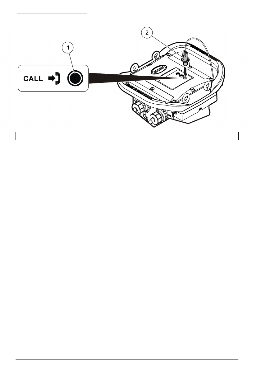
Figura 12 Chiamata al server
1 Destinazione avvio chiamata 2 Magnete
Verificare la telemetria con FSDATA Desktop
1. In FSDATA Desktop, selezionare Communications>Modem Diagnostics
(Comunicazioni>Modem>Diagnostica).
2. Assicurarsi che lo stato della registrazione sia home o roaming. Se non sono visualizzate
informazioni o è indicato "identify" (identificazione), la connessione è interrotta.
3. Regolare l'antenna per ottenere una potenza e una qualità del segnale ottimali.
4. Fare clic su Call Server (Chiama server) per effettuare una chiamata alla rete.
Viene visualizzata una schermata pop-up per comunicare se l'operazione è riuscita o meno.
Telemetria per individuazione ed eliminazione dei guasti
• Verificare la correttezza del codice di verifica server (SVC).
• Verificare che il numero di serie sia registrato e attivo sul server host.
• Verificare che il modem sia abilitato e che l'indirizzo IP Hach sia stato immesso correttamente.
• Se il problema persiste, contattare l'assistenza tecnica.
Uso dell'opzione SMS mobile
Configurare il modem FL900 per l'invio o la ricezione dei messaggi SMS (opzionale). Per ulteriori
informazioni, fare riferimento alla documentazione relativa a FSDATA Desktop.
Comunicazione Modbus
Il protocollo Modbus può essere utilizzato per la comunicazione con questo strumento. Collegare un
dispositivo di rete esterno (ad esempio una PLC) all'interfaccia RS232 dello strumento per leggere i
dati ma mano che vengono registrati.
Contattare il supporto tecnico per ulteriori informazioni sulle comunicazioni Modbus.
Nota: i dati della cronologia non possono letti mediante la comunicazione Modbus.
Configurazione di base
Le informazioni contenute in questo manuale possono essere utilizzate per creare un semplice
programma per il logger e per calibrare i sensori. Per le opzioni avanzate fare riferimento alla
documentazione relativa a FSDATA Desktop. Leggere le sezioni nell'ordine in cui sono riportate.
72
Italiano
Page 73

Creazione di un programma del logger
Per specificare i canali da registrare con il logger, è necessario scrivere un programma.
1. Avviare una sessione di comunicazione con il logger:
a. Aprire FSDATA Desktop.
b. Fare clic su CONNECT (Collega). Viene visualizzata la finestra di collegamento allo
strumento.
c. Fare clic sul pulsante FL900.
d. Selezionare sul computer la porta alla quale è collegato il logger (seriale o USB), quindi fare
clic su CONNECT (Collega).
Nota: se viene visualizzato un messaggio di mancata corrispondenza sensore, selezionare "Create new
program based on sensors connected" (Crea nuovo programma basato sui sensori collegati).
e. Assicurarsi che lo stato della connessione sia "connected" (collegato).
2. Completare l'inserimento delle informazioni nella scheda General Settings (Impostazioni
generali).
Opzione Descrizione
Site Identification (Identificazione sito) Inserire un nome univoco per il sito.
3. Selezionare i canali da registrare in Select Channels (Seleziona canali):
a. Espandere la struttura ad albero del gruppo Logger channel. Il canale Power Supply si trova
sempre in questo gruppo. La registrazione dell'alimentazione fornisce i valori del livello della
batteria. È possibile impostare un allarme a un determinato livello per avvisare il gestore
account del raggiungimento di un basso livello, suggerendo una visita sul campo per
cambiare le batterie e impedire la perdita di dati. Se il logger contiene una porta per un
pluviometro, viene visualizzato anche il canale Rain. Per includere un canale del logger nel
registro dati, selezionare la casella di controllo accanto al nome del canale.
b. Espandere la struttura ad albero per ciascun gruppo di canali Port[1] (nome del sensore) per
visualizzare i canali disponibili per il sensore. Se la casella di controllo accanto a Logger o
Port[1] è selezionata, tutti i canali del gruppo vengono automaticamente selezionati.
c. Per includere un canale del sensore nel registro dati, selezionare la casella di controllo
accanto al nome del canale. Il numero di canali nel registro aumenta ogni volta che si
seleziona un nuovo canale.
Nota: per i logger dotati di più porte per i sensori, il numero della porta viene aggiunto al nome del canale.
Ad esempio, Velocity 3 è il nome del canale della velocità per la porta del sensore n. 3.
4. Per impostare l'intervallo di registrazione per un gruppo di canali:
a. Fare clic sul nome del gruppo di canali, ad esempio Port1 (Flo-Dar). Vengono visualizzati gli
intervalli di registrazione.
Italiano
73
Page 74

b. Selezionare l'intervallo dall'elenco a discesa. L'intervallo di registrazione primario si utilizza
per il funzionamento normale. L'intervallo di registrazione secondario si utilizza durante le
condizioni di allarme.
Nota: L'intervallo di registrazione non può essere impostato per un singolo canale del sensore.
5. Fare clic su WRITE TO LOGGER (SCRIVI SU LOGGER) per salvare le impostazioni. Viene
visualizzata una finestra:
Opzione Descrizione
Warning: all data will be
lost. Continue? (Avviso:
tutti i dati andranno persi.
Continuare?)
Set Logger Clock (Imposta
orologio logger)
Tutti i dati memorizzati nel logger vengono cancellati quando si scrive un
programma sul logger. Per salvare i dati, selezionare No e scaricarli in una
posizione sicura. Per cancellare tutti i dati e aggiornare il logger con il nuovo
programma, selezionare Yes (Sì).
Sincronizzazione con l'orologio del computer: il logger utilizza le impostazioni
di data e ora del computer. Impostazione dell'orologio del logger: il logger
utilizza le impostazioni di data e ora inserite dall'utente. Se l'unità è dotata di
modem, il logger utilizza automaticamente le impostazioni di data e ora del
server.
Calibrazione del sensore con l'apposita procedura guidata
Prerequisito: per la calibrazione, il logger deve essere collegato al computer ed essere online.
Il sensore può essere configurato e calibrato mediante una calibrazione guidata.
1. Fare clic sulla scheda Sensors (Sensori).
2. Fare clic su Sensor Port[1] (nome del sensore).
3. Fare clic sul pulsante CAL WIZARD. Viene aperta la finestra della calibrazione guidata.
4. Selezionare le opzioni desiderate in ogni schermata. Quando viene visualizzata la schermata
Calibration Complete, fare clic su FINISH.
5. Fare clic su WRITE TO LOGGER (SCRIVI SU LOGGER) per salvare le impostazioni. Viene
visualizzata una finestra:
Opzione Descrizione
Warning: all data will be
lost. Continue? (Avviso:
tutti i dati andranno persi.
Continuare?)
Set Logger Clock (Imposta
orologio logger)
Tutti i dati memorizzati nel logger vengono cancellati quando si scrive un
programma sul logger. Per salvare i dati, selezionare No e scaricarli in una
posizione sicura. Per cancellare tutti i dati e aggiornare il logger con il nuovo
programma, selezionare Yes (Sì).
Sincronizzazione con l'orologio del computer: il logger utilizza le impostazioni
di data e ora del computer. Impostazione dell'orologio del logger: il logger
utilizza le impostazioni di data e ora inserite dall'utente. Se l'unità è dotata di
modem, il logger utilizza automaticamente le impostazioni di data e ora del
server.
L'installazione è stata completata. Se la programmazione ha avuto esito positivo, la spia di stato
dovrebbe lampeggiare in verde.
Installazione nel sito
A V V ER T E N Z A
Pericoli multipli. Gli interventi descritti in questa sezione del documento devono essere eseguiti solo da
personale qualificato.
74 Italiano
Page 75

Appendere l'unità a un cavo
A V V I S O
Non utilizzare le maniglie per appendere il logger. Le maniglie non sono in grado di sorreggere il peso del logger.
Il logger può essere installato appendendolo con un cavo in aree quali, ad esempio, chiusini.
1. Inserire un cavo nelle viti a occhiello sulla parte superiore del logger. Fare riferimento a
Figura 13.
2. Appendere il cavo a un supporto resistente, ad esempio la barra di una trave.
Figura 13 Appendere il logger a un cavo
Installazione su una staffa a muro
Il logger può essere installato su una parete, un palo o una scala. Fare riferimento alla
documentazione fornita con l'hardware le istruzioni di installazione.
Manutenzione
A V V ER T E N Z A
Pericoli multipli. Gli interventi descritti in questa sezione del documento devono essere eseguiti solo da
personale qualificato.
A V V ER T E N Z A
Rischio biologico. Rispettare i protocolli di sicurezza e indossare tutti i dispositivi di protezione
individuale richiesti durante la manipolazione di uno strumento che potrebbe entrare in contatto con
materiali pericolosi. Lavare e decontaminare lo strumento con una soluzione di sapone disinfettante e
sciacquare con acqua calda prima della manutenzione o della spedizione.
Italiano 75
Page 76

A T T EN ZI O N E
Pericolo di radiazioni elettromagnetiche. Assicurarsi che l'antenna si trovi a una distanza minima di
20 cm (7,9 pollici) da tutto il personale durante le normali operazioni. L'antenna non può essere
collocata nella stessa posizione o utilizzata insieme ad altre antenne o trasmettitori.
Pulizia dello strumento
Pulire le superfici esterne dello strumento con un panno inumidito con una soluzione contenente
sapone delicato; quindi asciugare lo strumento secondo necessità.
Sostituzione delle batterie
Sostituire le batterie con batterie dello stesso tipo e caratteristiche. Fare riferimento a Installazione
delle batterie a pagina 61 e Specifiche tecniche a pagina 54.
Sostituzione dell'essiccante
L'essiccante è contenuto nel vano batterie. Per rimuovere il coperchio del vano batterie, fare
riferimento a Installazione delle batterie a pagina 61. L'essiccante assorbe l'umidità dall'aria e
impedisce la corrosione dei componenti dello strumento. I granuli di essiccante cambiano colore
quando diventano saturi. Sostituire l'essiccante quando i granuli diventano da gialli a verdi (fare
riferimento a Figura 14). Si consiglia di sostituire l'essiccante quando si sostituiscono le batterie.
Figura 14 Sostituzione dell'essiccante
Individuazione ed eliminazione dei guasti
Se si verifica un problema con il sistema, tentare di capire se il problema riguarda il sensore, il logger
o il collegamento dei cavi.
• Ispezionare tutti i collegamenti al sensore. Accertarsi che i cavi non si siano allentati.
• Rimuovere ed esaminare i connettori dei sensori per individuare eventuali tracce di umidità. Se
necessario, pulirli e asciugarli.
• Esaminare i sensori per individuare eventuali residui e rimuoverli.
• Consultare il registro eventi per verificare se sono stati registrati eventi connessi al problema.
Errore di comunicazione
Se è stata inviata una chiamata al server ma non viene stabilita una connessione, procedere come
descritto di seguito:
76
Italiano
Page 77

• Spegnere e riaccendere lo strumento.
• Regolare l'antenna per aumentare la potenza del segnale.
• Accedere al server e verificare che il numero di serie immesso sia corretto e che il codice di
verifica server (SVC) utilizzato per la configurazione sia stato correttamente registrato.
• Assicurarsi che le impostazioni di comunicazione siano state immesse correttamente nella finestra
del driver di FL900.
• Collegare il logger al computer e avviare una sessione di comunicazione. Nella finestra del driver
di FL900, fare clic sulla scheda Diagnostics, quindi sul menu Modem. Lo stato della registrazione
indicato deve essere Home.
• Se non si trova alcuna risoluzione, chiamare l'assistenza tecnica.
Parti di ricambio e accessori
Nota: Numeri di Prodotti e Articoli possono variare per alcune regioni di vendita. Contattare il distributore
appropriato o fare riferimento al sito Web dell'azienda per dati di contatto.
Parti di ricambio
Descrizione Articolo n.
Coperchio vano batterie 8524400
Coperchio vano batteria, o-ring 8533400
Gruppo coperchio essiccante (essiccante vano batterie) 8754900
Gruppo tubo essiccante (essiccante vano batterie) 8535200
Essiccante, perle sostitutive, 680 g (1,5 lb) 8755500
Viti a occhiello, 1/4-20 x 2,5 pollici acciaio inox 8535500
Guarnizione, coperchio superiore 8533300
Vite involucro, #10–14 x 1 pollici 8753300
Maniglia logger 8524200
Lubrificante, silicone 0,25 once 000298HY
Gruppo magnete 8537800
Coperchio e cordino per sensore, connettori Comm o Aux 8535000
Coperchio e cordino per connettore pluviometro 9492500
Alimentazione
Descrizione Articolo n.
Batteria da 6 V, lanterna 11013M
Batteria alcalina a lunga durata 8542900
Adattatore e cavo coperchio pacco batterie alcaline a lunga durata 8543000
Gruppo cavo, alimentazione esterna, 2,7 m (9 piedi) 8528700
Gruppo cavo, alimentazione esterna, 7,6 m (25 piedi) 8528701
Italiano 77
Page 78

Bulloneria di montaggio
Descrizione Articolo n.
Staffa per montaggio a parete senza gancio per scala 8542700
Adattatore staffa per montaggio a muro 8543800
Antenne
Descrizione Articolo n.
A lama, 3G/4G LTE, 3 dBi 8623800
Ad aletta, 2G/3G/4G LTE, cavo da 2,5 m (8,2 piedi), 5,5 dBi 8624000
Da interramento, 3G/4G LTE, cavo da 3 m (9,8 piedi), 3 dBi 8624200
Coperchio pozzetto, 3G/4G LTE, cavo da 3 m (9,8 piedi), 3 dBi 8624400
Cavi ausiliari/campionatore
Descrizione Articolo n.
Cavo, ausiliario, parziale multiuso, 7 pin, 2,7 m (9 piedi) 8528500
Cavo, ausiliario, parziale multiuso, 7 pin, 7,6 m (25 piedi) 8528501
Cavo, da porta AUX logger FL900 a AS950, 7 pin, 2,7 m (9 piedi) 9500700
Cavo, da porta AUX logger FL900 a AS950, 7 pin, 7,6 m (25 piedi) 9500701
Gruppo cavo, AUX di ingresso alimentazione, AS950-FL900 con adattatore di
alimentazione
8322800
78 Italiano
Page 79

Table des matières
Caractéristiques techniques à la page 79 Configuration de base à la page 98
Généralités à la page 80 Installation in situ à la page 100
Mise sous tension de l'enregistreur à la page 86 Maintenance à la page 101
Démarrage du système à la page 89 Dépannage à la page 102
Programmation d'une unité équipée d'un modem
à la page 91
Communication Modbus à la page 98
Pièces de rechange et accessoires
à la page 103
Informations supplémentaires
Des informations supplémentaires sont disponibles sur le site Web du fabricant.
Caractéristiques techniques
Ces caractéristiques sont susceptibles d'être modifiées sans avis préalable.
Caractéristique Détails
Dimensions (l x P x H) 25,4 x 22 x 40 cm (10,0 x 8,7 x 16,0 pouces)
Boîtier Mousse structurée PC/ABS
Classement environnemental NEMA 6P/IP68 (submersion 24 heures à 1,8 m (6 pieds))
Poids (modèle FL900) 4,5 kg (10 lb) sans piles, 6,3 kg (14 lb) avec 2 piles et 8,2 kg (18 lb) avec
Température de fonctionnement –18 à 60 ºC (0 à 140 ºF) à 95 % HR
Température de stockage –40 à 60 °C (-40 à 140 °F)
Alimentation électrique 8 à 18 VCC avec des piles ou une source d'alimentation externe, 2,5 W
Durée de vie de la batterie Varie selon le type de capteur, les intervalles d'enregistrement, la télémétrie
Catégorie d'installation I
Classe de protection III
Niveau de pollution 4
Ports du capteur 1, 2 ou 4 ports
Connecteurs Connecteurs en acier inoxydable
Voies d'enregistrement 16 maximum
Alarmes Jusqu'à 16 alarmes avec options élevé/élevé, élevé, faible, faible/faible. Les
4 piles
maximum
et l'environnement.
Avec un intervalle d'enregistrement de 15 minutes, sans modem, quatre piles
6 V à température ambiante :
• Capteur Flo-tote 306 jours
• Capteur de vitesse avec analyseur AV9000 296 jours
• Capteur Flo-Dar 185 jours
• Capteur ultrasonique 456 jours
Remarque : Pour des durées plus longues, utilisez des piles longue durée, ref. 8542900.
alarmes du système sont sur pile faible, une pile RTC faible, mémoire faible,
mémoire slate pleine, non réponse du capteur et identifiant de capteur.
Français 79
Page 80
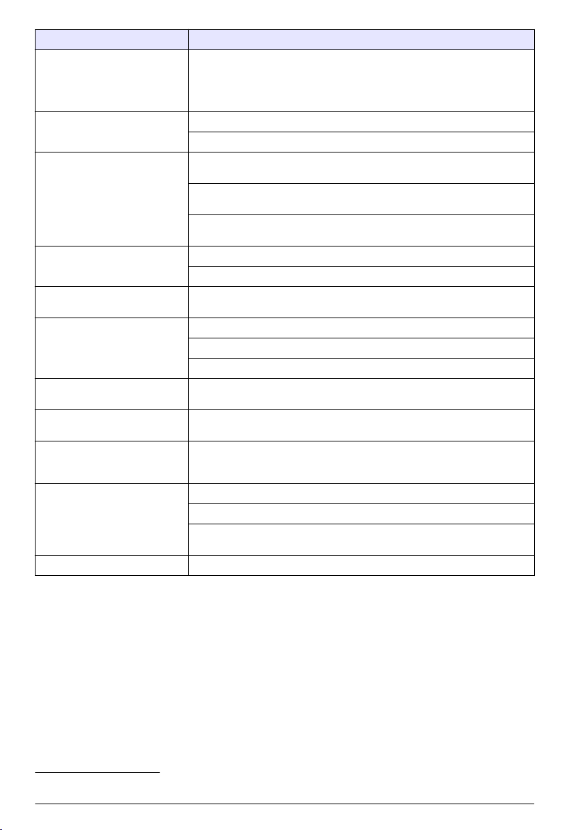
Caractéristique Détails
Actions d'alarme A partir de l'enregistreur ou du serveur, vous pouvez démarrer
Intervalles d'enregistrement 1, 2, 3, 4, 5, 6, 10, 12, 15, 20, 30 ou 60 minutes
Stockage des données Journal des événements : jusqu'à 1 000 événements dans une mémoire flash
Communication avec
l'ordinateur.
Communication à distance (en
option)
Protocoles Modbus RTU (RS232)
Précision de la base de temps ± 0,002 %, synchronisation toutes les 24 heures avec logiciel serveur et
Capteurs pris en charge Flo-Dar, Flo-Dar avec SVS, Flo-Tote, Pluviomètre, ultrasonique, sonde
Interface de l’échantillonneur Compatible avec Sigma 900 Standard, Sigma 900 Max , Hach SD900 et
Certifications Enregistreur : CE
Garantie 1 an
l'échantillonneur, modifier l'intervalle d'enregistrement, modifier l'intervalle
d'appel et envoyer un courrier électronique ou un SMS.
Remarque : Des frais peuvent s'appliquer pour les SMS. Certains types d'alarme peuvent
ne pas être disponibles avec tous les opérateurs cellulaires ni toutes les offres de service.
Intervalles principaux et secondaires pour un enregistrement dynamique
non-volatile
Historique de l'échantillonneur : jusqu'à 2 000 événements d'échantillonnage
dans une mémoire flash non-volatile
Datalog : 325 000 valeurs mesurées ; 1 128 jours pour 3 voies à 15 minutes
d'intervalle d'enregistrement
USB
RS232 (débits en bauds : 9 600, 19 200, 38 400, 57 600, 115 200)
Modem sans fil : 3G, 4G LTE (Verizon) ; 3G, 4G LTE, PTCRB (Etats-Unis et
Canada)
SMS MT
SMS MO
modem
hauteur/vitesse1, Sigma 950
AS950 pour l'échantillonnage des points de consigne, la vitesse d'écoulement
et l'enregistrement de l'historique des échantillons
Alimentation CA en option : normes UL/CSA (cETLus)/CE
Modems : FCC, IC. Si vous souhaitez d'autres modèles, veuillez contacter le
fabricant pour de plus amples informations.
1
Généralités
En aucun cas le constructeur ne saurait être responsable des dommages directs, indirects, spéciaux,
accessoires ou consécutifs résultant d'un défaut ou d'une omission dans ce manuel. Le constructeur
se réserve le droit d'apporter des modifications à ce manuel et aux produits décrits à tout moment,
sans avertissement ni obligation. Les éditions révisées se trouvent sur le site Internet du fabricant.
1
Cet appareil se raccorde via un module externe.
80 Français
Page 81
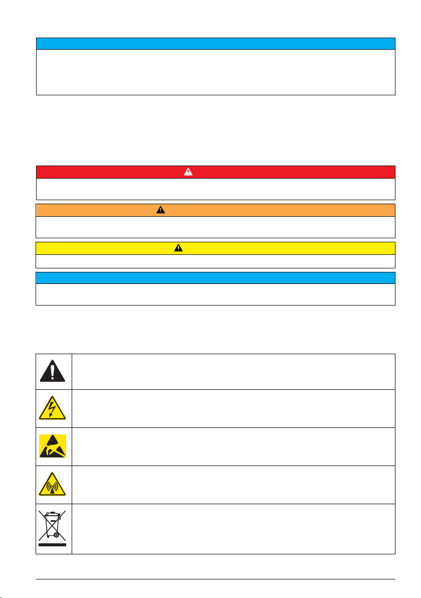
Consignes de sécurité
A V I S
Le fabricant décline toute responsabilité quant aux dégâts liés à une application ou un usage inappropriés de ce
produit, y compris, sans toutefois s'y limiter, des dommages directs ou indirects, ainsi que des dommages
consécutifs, et rejette toute responsabilité quant à ces dommages dans la mesure où la loi applicable le permet.
L'utilisateur est seul responsable de la vérification des risques d'application critiques et de la mise en place de
mécanismes de protection des processus en cas de défaillance de l'équipement.
Veuillez lire l'ensemble du manuel avant le déballage, la configuration ou la mise en fonctionnement
de cet appareil. Respectez toutes les déclarations de prudence et d'attention. Le non-respect de
cette procédure peut conduire à des blessures graves de l'opérateur ou à des dégâts sur le matériel.
Assurez-vous que la protection fournie avec cet appareil n'est pas défaillante. N'utilisez ni n'installez
cet appareil d'une façon différente de celle décrite dans ce manuel.
Interprétation des indications de risques
Indique une situation de danger potentiel ou imminent qui, si elle n'est pas évitée, entraîne des blessures graves,
voire mortelles.
D A N GE R
A V E RT I S S E M E N T
Indique une situation de danger potentiel ou imminent qui, si elle n'est pas évitée, peut entraîner des blessures
graves, voire mortelles.
Indique une situation de danger potentiel qui peut entraîner des blessures mineures ou légères.
Indique une situation qui, si elle n'est pas évitée, peut occasionner l'endommagement du matériel. Informations
nécessitant une attention particulière.
A T T EN T I O N
A V I S
Etiquettes de mise en garde
Lisez toutes les étiquettes et tous les repères apposés sur l'instrument. Des personnes peuvent se
blesser et le matériel peut être endommagé si ces instructions ne sont pas respectées. Un symbole
sur l'appareil est signalé dans le manuel avec une instruction de mise en garde.
Ceci est le symbole d'alerte de sécurité. Se conformer à tous les messages de sécurité qui suivent ce
symbole afin d'éviter tout risque de blessure. S'ils sont apposés sur l'appareil, se référer au manuel
d'utilisation pour connaître le fonctionnement ou les informations de sécurité.
Ce symbole indique qu'il existe un risque de choc électrique et/ou d'électrocution.
Ce symbole indique la présence d'appareils sensibles aux décharges électrostatiques et indique que
des précautions doivent être prises afin d'éviter d'endommager l'équipement.
Ce symbole signale la présence d'ondes radioélectriques.
Le matériel électrique portant ce symbole ne doit pas être mis au rebut dans les réseaux domestiques
ou publics européens. Retournez le matériel usé ou en fin de vie au fabricant pour une mise au rebut
sans frais pour l'utilisateur.
Français 81
Page 82

Précautions concernant l'espace confiné
D A N GE R
Risque d’explosion Une formation portant sur les tests de pré-entrée, la ventilation, les procédures
d'entrée, les procédures d'évacuation/de sauvetage et les mesures de sécurité est nécessaire avant
d'entrer dans des lieux confinés.
Les informations suivantes sont fournies dans le but d'aider les utilisateurs à appréhender les
dangers et les risques associés aux espaces confinés.
Le 15 avril 1993, le règlement final de l'OSHA concernant le CFR 1910.146, Permit Required
Confined Spaces (Espaces confinés nécessitant l'autorisation), est devenue une loi. Cette norme
affecte directement plus de 250 000 sites industriels aux Etats-Unis et a été rédigée dans le but de
protéger la santé et la sécurité des travailleurs en espace confiné.
Définition d'un espace confiné :
Tout endroit ou clôture qui présente (ou est susceptible de présenter) une ou plusieurs des
conditions suivantes :
• Une atmosphère qui contient une concentration d'oxygène inférieure à 19,5 % ou supérieure à
23,5 % et/ou une concentration de sulfure d'hydrogène (H2S) supérieure à 10 ppm.
• Une atmosphère qui peut être inflammable ou explosive en présence de gaz, vapeurs, brumes,
poussières ou fibres.
• Des matériaux toxiques qui, en cas de contact ou d'inhalation, sont susceptibles d'occasionner
des blessures, des problèmes de santé ou la mort.
Les espaces confinés ne sont pas conçus pour l'occupation humaine. Les espaces confinés
disposent d’un accès limité et présentent des risques connus ou potentiels. Les trous d’homme, les
colonnes, les tuyaux, les cuves, les chambres de commutation et autres emplacements similaires
sont des exemples d’espaces confinés.
Il convient de toujours suivre les procédures de sécurité standard avant d'entrer dans des espaces
et/ou des endroits confinés soumis à des gaz dangereux, des vapeurs, des brumes, des poussières
ou des fibres Avant de pénétrer dans un espace confiné, veuillez lire l'ensemble des procédures
liées à l'accès.
Certification
Règlement canadien sur les équipements causant des interférences radio, IECS-003, Classe
A:
Les données d'essai correspondantes sont conservées chez le constructeur.
Cet appareil numérique de classe A répond à toutes les exigences de la réglementation canadienne
sur les équipements provoquant des interférences : CAN ICES-3(A)/NMB-3(A).
Cet appareil numérique de classe A répond à toutes les exigences de la réglementation canadienne
sur les équipements provoquant des interférences.
FCC part 15, limites de classe A :
Les données d'essai correspondantes sont conservées chez le constructeur. L'appareil est conforme
à la partie 15 de la règlementation FCC. Le fonctionnement est soumis aux conditions suivantes :
1. Cet équipement ne peut pas causer d'interférence nuisible.
2. Cet équipement doit accepter toutes les interférences reçues, y compris celles qui pourraient
entraîner un fonctionnement inattendu.
Les modifications de cet équipement qui n’ont pas été expressément approuvées par le responsable
de la conformité aux limites pourraient annuler l’autorité dont l’utilisateur dispose pour utiliser cet
équipement. Cet équipement a été testé et déclaré conforme aux limites définies pour les appareils
numériques de classe A, conformément à la section 15 de la réglementation FCC. Ces limites ont
pour but de fournir une protection raisonnable contre les interférences néfastes lorsque l’équipement
fonctionne dans un environnement commercial. Cet équipement génère, utilise et peut irradier
l'énergie des fréquences radio et, s'il n'est pas installé ou utilisé conformément au mode d'emploi, il
peut entraîner des interférences dangereuses pour les communications radio. Le fonctionnement de
82
Français
Page 83
cet équipement dans une zone résidentielle risque de causer des interférences nuisibles, dans ce
cas l'utilisateur doit corriger les interférences à ses frais Les techniques ci-dessous peuvent
permettre de réduire les problèmes d'interférences :
1. Débrancher l'équipement de la prise de courant pour vérifier s'il est ou non la source des
perturbations
2. Si l'équipement est branché sur le même circuit de prises que l'appareil qui subit des
interférences, branchez l'équipement sur un circuit différent.
3. Éloigner l'équipement du dispositif qui reçoit l'interférence.
4. Repositionner l’antenne de réception du périphérique qui reçoit les interférences.
5. Essayer plusieurs des techniques ci-dessus à la fois.
Certification de modem sans fil
Le produit répond aux exigences de la section 15 de la réglementation FCC et aux normes RSS
d'Industrie Canada. Le fonctionnement est soumis aux conditions suivantes :
1. Cet équipement ne peut pas causer d'interférence nuisible.
2. Cet équipement doit accepter toutes les interférences reçues, y compris celles qui pourraient
entraîner un fonctionnement inattendu.
Les modifications de cet équipement de communication sans fil qui n’ont pas été expressément
approuvées par le responsable de la conformité aux limites pourraient annuler l’autorité dont
l’utilisateur dispose pour utiliser cet équipement. Tout changement apporté à l'équipement annulera
la certification d'Industrie Canada et l'autorisation FCC. Les changements et modifications incluent
toute modification effectuée sur les modems sans fil et les antennes associées, y compris les câbles
d'antenne. Suivez les recommandations du fabricant pour l'installation, la configuration et l'utilisation
sans fil du produit.
Appareils cellulaires
A V I S
La sécurité du réseau et du point d'accès relève de la responsabilité du client utilisant l'appareil sans fil. Le
fabricant ne peut être tenu pour responsable des dommages indirects, particuliers, fortuits ou accessoires
occasionnés en raison d'une violation de la sécurité du réseau.
A V E RT I S S E M E N T
Précautions relatives aux stimulateurs cardiaques. Si des interférences électromagnétiques (IEM) se
produisent, elles peuvent :
• Interrompre les impulsions du stimulateur cardiaque qui contrôle le rythme du cœur.
• Perturber la régularité des impulsions du stimulateur cardiaque.
• Empêcher le stimulateur cardiaque de tenir compte du rythme du cœur, l'obligeant à donner des
impulsions à un intervalle défini.
Des recherches en cours montrent que les appareils cellulaires ne posent pas de problème de santé
significatif pour les porteurs de stimulateur cardiaque. Cependant, les personnes portant un stimulateur
cardiaque doivent faire preuve de prudence et s'assurer que leur appareil ne leur pose pas de
problème. Maintenez l'appareil à une distance d'au moins 20 cm (7,9 pouces) de l'utilisateur.
Risque lié au rayonnement électromagnétique. Assurez-vous que l'antenne se trouve à une distance
minimum de 20 cm (7,9 pouces) de l'ensemble du personnel dans des conditions d'utilisation dites
normales. L'antenne ne peut pas être colocalisée ou utilisée en combinaison avec une autre antenne ou
d'autres transmetteurs.
Risque lié au rayonnement électromagnétique. Dans les applications portables, n'utilisez pas le modem
à moins de 20 cm (7,9 pouces) de l'utilisateur.
A T T EN T I O N
A T T EN T I O N
Français 83
Page 84
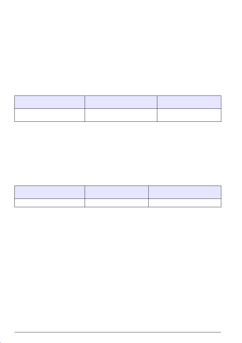
Agréments des dispositifs de contrôle RF
Modem MTSMC-LAT3 (classe d'équipement : transmetteur sous licence PCS, module LTE/3G) :
• FCC : homologué en tant qu'appareil modulaire avec octroi d'autorisation TCB. ID FCC :
RI7LE910NAV2
• IC : homologué en tant qu'appareil modulaire avec certificat d'acceptabilité technique, ID C-REL :
5131A-LE910NAV2
Modem MTSMC-LVW3 (transmetteur sous licence PCS, module LTE/3G) :
• FCC : homologué en tant qu'appareil modulaire avec octroi d'autorisation TCB. ID FCC :
RI7LE910SVV2
• IC : homologué en tant qu'appareil modulaire avec certificat d'acceptabilité technique, ID C-REL :
5131A-LE910SVV2
Tableau 1 Modem cellulaire : MTSMC-LAT3
Sections de la réglementation FCC Bandes de fréquence (MHz) Puissance de sortie maximale
22, 24, 27 700 (B12/ B13), 850 (B5), 1 700 (B4),
1 900 (B2)
(Watts)
0.232
Modem cellulaire MTSMC-LAT3, conditions d'octroi et remarques :
Approbation modulaire unique. Vérification de la puissance en sortie. Cet appareil est homologué
pour les utilisations fixes et mobiles en termes de conformité aux limites d'exposition aux fréquences
radio et ne peut être distribué qu'à des installateurs OEM. La ou les antennes utilisées pour ce
transmetteur, telles que décrites dans cette déclaration, doivent être installées avec une distance de
séparation d'au moins 20 cm par rapport à la personne la plus proche. Vous devez mettre en place
un environnement d'exploitation conforme aux normes d'exposition aux fréquences radio. Valeurs
maximales de gain d'antenne/perte sur câble : 6.63 dBi pour 700 MHz et 850 MHz ; 6,00 dBi pour
1 700 MHz ; 8.51 dBi pour 1 900 MHz.
Tableau 2 Modem cellulaire : MTSMC-LVW3
Sections de la réglementation FCC Bandes de fréquence (MHz) Puissance de sortie maximale
24, 27 700 (B13), 1 700 (B4), 1 900 (B2) 0.219
(Watts)
Modem cellulaire MTSMC-750 LB3, conditions d'octroi et remarques :
Approbation modulaire unique. Vérification de la puissance en sortie. Cet appareil est homologué
pour les utilisations fixes et mobiles en termes de conformité aux limites d'exposition aux fréquences
radio et ne peut être distribué qu'à des installateurs OEM. La ou les antennes utilisées pour ce
transmetteur, telles que décrites dans cette déclaration, doivent être installées avec une distance de
séparation d'au moins 20 cm par rapport à la personne la plus proche. Vous devez mettre en place
un environnement d'exploitation conforme aux normes d'exposition aux fréquences radio. Valeurs
maximales de gain d'antenne/perte sur câble : 6,94 dBi pour 700 MHz ; 6,00 dBi pour 1 700 MHz ;
9,01 dBi pour 1 900 MHz.
Présentation du produit
Les enregistreurs d'écoulement série FL900 sont utilisés dans le cadre d'études de contrôle
d'écoulement à surface libre sur le débit et l'infiltration, les débordements d'égouts unitaires (DEU), la
capacité de débit et la planification, et le contrôle des eaux pluviales d'orage.
Les données sont recueillies par les capteurs raccordés à l'enregistreur et enregistrées pour être
extraites ultérieurement. Il est possible d'ajouter ou de modifier les capteurs sur le terrain. En
fonction du modèle, vous pouvez raccorder jusqu'à 4 capteurs. Les données peuvent être
récupérées directement via le port USB ou un câble RS232, ou encore à distance via un réseau sans
fil avec FSDATA Desktop et le logiciel serveur FSDATA. Les enregistreurs série FL900 peuvent
84
Français
Page 85
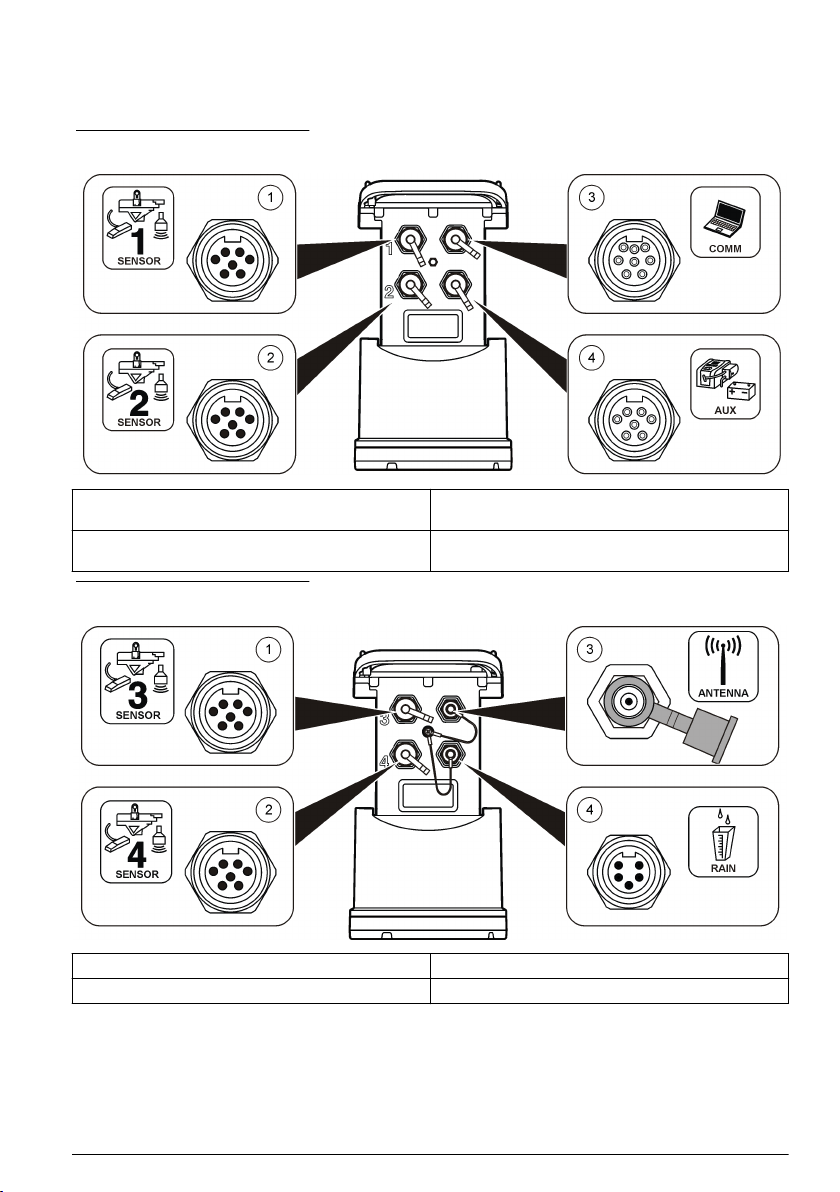
également être raccordés à une source d'alimentation externe, un pluviomètre ou être utilisés pour
régler la vitesse d'un échantillonneur Sigma ou Hach.
L'option sans fil et le nombre de connecteurs disponibles varient selon le modèle de l'enregistreur.
Reportez-vous aux sections Figure 1 et Figure 2.
Figure 1 Connecteurs : côté 1
1 Capteur (tous les modèles) 3 Ordinateur : câble USB ou RS232 (tous les
2 Capteur (FL902 et FL904 uniquement) 4 Auxiliaire : alimentation externe ou échantillonneur
modèles)
(tous les modèles, sauf FL900)
Figure 2 Connecteurs : côté 2
1 Capteur (FL904 uniquement) 3 Option antenne (tous les modèles, sauf FL900)
2 Capteur (FL904 uniquement) 4 Pluviomètre (tous les modèles, sauf FL900)
Composants du produit
Si des éléments manquent ou sont endommagés, contactez immédiatement le fabricant ou un
représentant commercial.
Français
85
Page 86
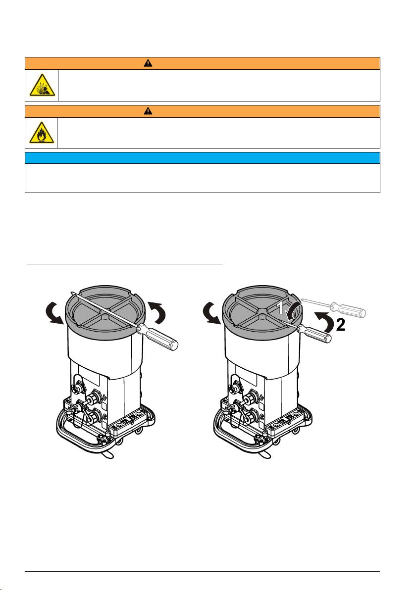
Mise sous tension de l'enregistreur
Installation des piles
A V E RT I S S E M E N T
Risque d’explosion Une installation incorrecte des piles peut libérer des gaz explosifs. Veillez à ce que
les piles soient du même type chimique homologué et qu'elles soient insérées dans le bon sens. Ne
mélangez pas des piles neuves et des piles usagées.
A V E RT I S S E M E N T
Risque d’incendie. La substitution du type de pile n'est pas autorisée. Utilisez uniquement des piles
alcalines.
Ne serrez pas excessivement le cache. Serrez jusqu'à ce que le cache effleure le joint torique, puis d'un quart de
tour à un demi-tour maximum à partir de l'effleurement avec le joint torique. Lubrifiez régulièrement le joint torique
avec de la graisse de silicone.
L'appareil peut être utilisé avec 2 ou 4 piles de 6 V. Utilisez deux piles pour une utilisation courte ou
quatre piles pour une utilisation longue (pour la durée de vie des piles, reportez-vous à
Caractéristiques techniques à la page 79). Lorsque vous utilisez deux piles, placez-les du même
côté dans le compartiment (A-A ou B-B). Reportez-vous aux illustrations suivantes.
En cas de changements de température et de pression, il peut s'avérer difficile de retirer
manuellement le cache du compartiment à piles. Dans ce cas, vous pouvez utiliser un outil (
Figure 3).
Figure 3 Dépose du cache du compartiment à piles
A V I S
86 Français
Page 87

1 2
3
Français 87
Page 88
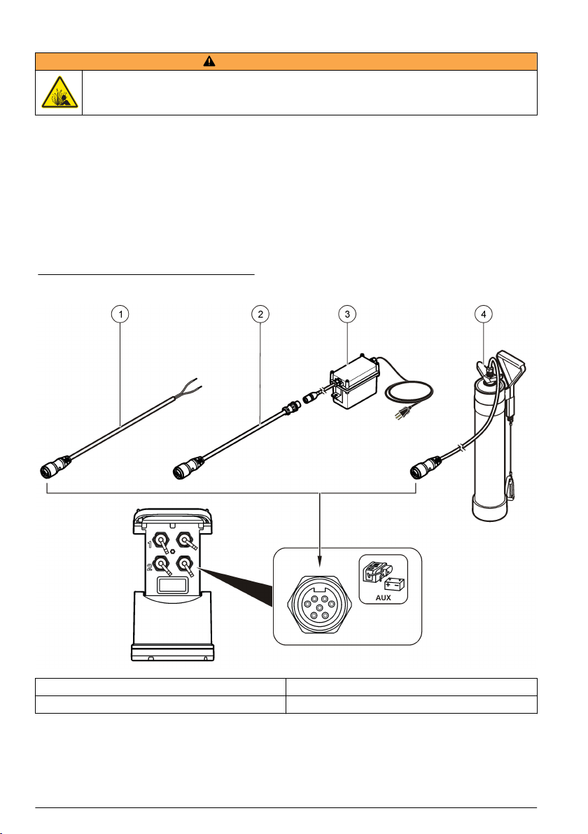
Raccordement d'une alimentation externe (en option)
A V E RT I S S E M E N T
Risque d'explosion. L'appareil n'est pas homologué pour une utilisation dans des conditions
dangereuses.
L'appareil peut être alimenté par une pile longue durée externe, une alimentation AS950 ou toute
autre source d'alimentation issue de la gamme spécifiée (reportez-vous aux sections
Caractéristiques techniques à la page 79 et Pièces de rechange et accessoires à la page 103). Si
l'enregistreur est doté d'une source d'alimentation externe et de piles internes, les piles sont utilisées
comme source d'alimentation auxiliaire. Lorsque l'alimentation externe est inférieure à 9 V environ,
les piles internes alimentent l'appareil jusqu'à ce que la tension de la source externe dépasse 9 V.
1. Installez la source d'alimentation externe dans un endroit sûr à proximité de l'enregistreur.
Assurez-vous de respecter toutes les mesures de sécurité en matière d'alimentation.
2. Reliez le câble de la source d'alimentation au connecteur AUX de l'enregistreur (Figure 4).
3. Raccordez l'appareil à la source d'alimentation, le cas échéant.
Figure 4 Options d'alimentation externe
1 Câble d'alimentation à 2 conducteurs (Figure 5) 3 Alimentation AS950
2 Câble adaptateur d'alimentation 4 Pile longue durée
88 Français
Page 89
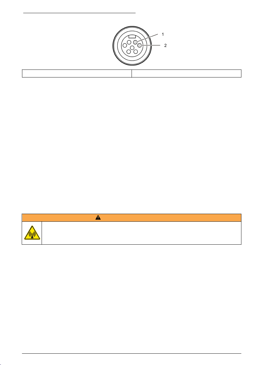
Figure 5 Câbles d'alimentation à 2 conducteurs
1 Puissance—fil rouge, 1,31 mm² 2 Commun—fil noir, 1,31 mm²
Démarrage du système
Installation de FSDATA Desktop sur un ordinateur
Avant de connecter l'enregistreur de débit ou l'échantillonneur à un ordinateur, vérifiez que
FSDATA Desktop est installé sur cet ordinateur. FSDATA Desktop est disponible à l'adresse
www.hachflow.com.
Raccordement de l'enregistreur à l'ordinateur
Conditions préalables : vérifiez que FSDATA Desktop est installé sur votre ordinateur.
Raccordez uniquement un enregistreur à l'ordinateur
1. Reliez l'enregistreur à l'ordinateur.
2. Lorsque vous raccordez un câble USB pour la première fois, l'assistant Nouveau matériel détecté
s'ouvre. Exécutez l'assistant du nouveau matériel pour installer le pilote USB de l'enregistreur.
Une fois terminé, le message « Votre nouveau matériel est installé et prêt à l'emploi » s'affiche. Si
l'assistant ne s'ouvre pas ou si l'installation échoue, contactez l'assistance technique pour qu'elle
vous aide à dépanner votre système d'exploitation spécifique.
Branchement du capteur ou des périphériques externes à l'enregistreur
Conditions préalables : l'état de la connexion doit être « Not connected » (Non connecté).
A V E RT I S S E M E N T
Emplacements dangereux pour le capteur et risques d'exposition aux radiofréquences. Certains
capteurs présentent des risques d'exposition au rayonnement RF et sont utilisés dans des
atmosphères explosives. Avant de brancher un capteur sur l'enregistreur, reportez-vous aux
avertissements et aux instructions du manuel du capteur.
Le nombre de capteurs qui peuvent être raccordés à l'enregistreur dépend du modèle de
l'enregistreur. Certains capteurs se branchent à un module externe servant d'interface entre le
capteur et l'enregistreur. Figure 7 montre le module d'analyse Hauteur/vitesse AV900 couplé à côté
de l'enregistreur et le branchement à un capteur de hauteur/vitesse.
1. Si le câble du capteur est équipé de connecteurs aux deux extrémités, raccordez d'abord le câble
au capteur.
2. Branchez le capteur (ou module) à n'importe quel port SENSOR de l'enregistreur Figure 6 ou
Figure 7. Serrez le connecteur à la main.
Remarque : Pour l'installation d'un pluviomètre, reliez le capteur au connecteur RAIN (PLUIE).
3. Si le capteur utilise un module externe, branchez le module à l'enregistreur, puis raccordez le
capteur au module (Figure 7).
4. Si le câble du capteur comporte un concentrateur déshydratant, alignez-le verticalement et
vérifiez que l'orifice de passage d'air pointe vers le bas (Figure 6).
Français
89
Page 90

Figure 6 Raccordement d'un capteur à l'enregistreur
Figure 7 Raccordement d'un capteur à un module externe
Raccordement d'un module externe
Vous devez utiliser un module externe pour servir d'interface entre certains types de capteur et
l'enregistreur. Le module externe se monte sur le côté de l'enregistreur (Figure 7 à la page 90).
Reportez-vous à la documentation fournie avec le module pour connaître les instructions de
montage.
90
Français
Page 91
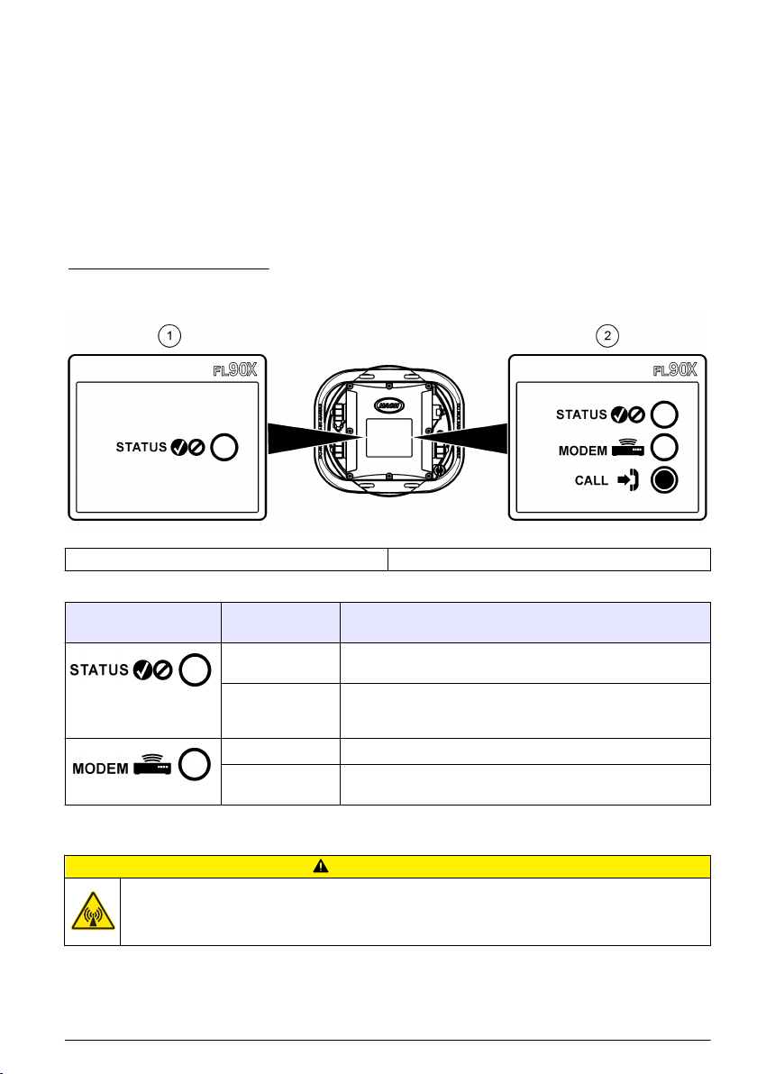
Raccordement d'un échantillonneur
L'enregistreur peut être branché sur un échantillonneur Sigma 900 Standard, Sigma 900 Max,
Hach SD900 ou Hach AS950 pour un échantillonnage réglé sur le débit et le point de consigne.
Connectez le port AUX de l'enregistreur au port auxiliaire de l'échantillonneur à l'aide d'un câble
auxiliaire. S'il convient de raccorder l'enregistreur à une alimentation externe lorsque celui-ci est
connecté à un échantillonneur AS950, utilisez l'ensemble de câblage auxiliaire pour entrée
alimentation secteur. Pour créer un programme d'échantillonnage, reportez-vous à la documentation
fournie avec l'échantillonneur.
Interface utilisateur
Les voyants de l'interface utilisateur affichent l'état de l'appareil et du modem. Reportez-vous à la
Figure 8 et au Tableau 3.
Figure 8 Interface utilisateur
1 Appareil sans modem 2 Appareil avec modem
Tableau 3 Voyants d'état DEL
Voyant Couleur du
voyant
Vert Clignote toutes les 3 secondes en fonctionnement normal.
Rouge Clignote lorsqu'un capteur raccordé n'est pas compatible avec
Vert Reste vert lors de l'émission d'un appel vers le serveur.
Rouge Clignotement de couleur rouge en cas d'échec de l'appel vers le
Description
Clignote toutes les 15 secondes en mode veille.
le programme de l'enregistreur, lorsqu'un capteur est
introuvable ou en cas de dysfonctionnement du capteur.
serveur.
Programmation d'une unité équipée d'un modem
A T T EN T I O N
Risque lié au rayonnement électromagnétique. Assurez-vous que l'antenne se trouve à une distance
minimum de 20 cm (7,9 pouces) de l'ensemble du personnel dans des conditions d'utilisation dites
normales. L'antenne ne peut pas être colocalisée ou utilisée en combinaison avec une autre antenne ou
d'autres transmetteurs.
Français 91
Page 92

Pour les unités sans modem, reportez-vous à la section Configuration de base à la page 98. Pour
les unités fournies avec des comptes modem activés2, reportez-vous à la section Ajout de
l'enregistreur au serveur FSDATA à la page 95.
Configuration du compte sans fil
Remarque : Vous devez vérifier que vous bénéficiez d'une couverture mobile suffisante de la part du fournisseur
que vous avez choisi pour chaque site avant d'acheter un enregistreur doté d'un modem mobile.
A V I S
La sécurité du réseau et du point d'accès relève de la seule responsabilité du client utilisant l'appareil sans fil. Le
fabricant ne peut être tenu pour responsable des dommages indirects, particuliers, fortuits ou accessoires
occasionnés en raison d'une violation de la sécurité du réseau.
Dès lors que l'enregistreur est équipé d'un modem, il est possible d'envoyer des données de
l'enregistreur vers Internet pour un accès à distance. L'utilisateur doit d'abord ouvrir un compte
auprès d'un opérateur de téléphonie mobile (sans fil). L'instrument est ensuite inscrit sur le serveur
hébergeant les données (FSDATA) et les réglages de communication applicables sont programmés
dans l'enregistreur avec FSDATA Desktop. Si le modem a été activé à l'usine, allez à Ajout de
l'enregistreur au serveur FSDATA à la page 95.
Conditions préalables : assurez-vous que l'enregistreur, le certificat de test de l'enregistreur et
l'antenne se trouvent à proximité.
Remarque : Pour un dépannage optimal, installez le pilote FSDATA Desktop, ajoutez l'enregistreur au serveur
FSDATA et vérifiez la télémétrie avant de visiter le site de déploiement.
1. Munissez-vous des informations de votre compte.
a. Identifiez le numéro IMEI sur l'étiquette. Reportez-vous à la Figure 9.
b. Recherchez le modèle de porteuse du modem indiqué sur l'étiquette.
2. Contactez un fournisseur de services sans fil pour mettre en service le modem. Assurez-vous
que le fournisseur de services sans fil correspond au type de modem de l'enregistreur, LVW3 =
Verizon ou LAT3 = PTCRB (AT&T, T-Mobile, etc.). Demandez un forfait données et SMS de
10 Mo minimum par mois. (SMS en option mais nécessaire pour les notifications d'alarme à un email ou numéro de mobile).
a. Indiquez le numéro IMEI au fournisseur. Le cas échéant, communiquez le modèle de
porteuse situé également sur l'étiquette de l'émetteur.
b. Relevez le numéro de téléphone du modem.
3. Utilisez l'option de diagnostic du modem dans FSDATA Desktop pour vérifier son
fonctionnement. Reportez-vous à la documentation de FSDATA Desktop.
2
Les numéros de référence des unités fournies avec des comptes modem activés se terminent
par .AX, .AR, .VX ou .VR.
92 Français
Page 93

Figure 9 Exemples d'étiquette d'émetteur
Installez une carte SIM
Dégât potentiel sur l'appareil Les composants électroniques internes de l'appareil peuvent être
endommagés par l'électricité statique, qui risque d'altérer ses performances et son fonctionnement.
A V I S
A V I S
Le boîtier de l'appareil peut se casser si les vis du couvercle sont trop serrées. Serrez les vis du couvercle à la
main à un couple de serrage maximum de 2 Nm (20 livrespouces). Assurez-vous que le joint est lubrifié.
Installez une carte SIM de l'opérateur de téléphonie mobile. Reportez-vous aux étapes illustrées
suivantes. Assurez-vous que le code PIN de la carte SIM est désactivé et que la carte SIM prend en
charge les données 4G LTE.
Français
93
Page 94

1 2
3 4
94 Français
Page 95

Raccordement d'une antenne (option sans fil)
A T T EN T I O N
Risque lié au rayonnement électromagnétique. Assurez-vous que l'antenne se trouve à une distance
minimum de 20 cm (7,9 pouces) de l'ensemble du personnel dans des conditions d'utilisation dites
normales. L'antenne ne peut pas être colocalisée ou utilisée en combinaison avec une autre antenne ou
d'autres transmetteurs.
Dans le cadre de communications sans fil, il est possible de brancher une antenne à l'appareil. Vous
avez le choix entre plusieurs types d'antenne. Reportez-vous à la Pièces de rechange et accessoires
à la page 103. Branchez l'antenne directement à l'enregistreur ou branchez un câble d'antenne au
connecteur ANTENNA (Figure 10).
Figure 10 Raccordement de l'antenne à lame
Ajout de l'enregistreur au serveur FSDATA
Conditions préalables : numéro de série de l'enregistreur
Figure 11 Emplacement du numéro de série
A V I S
Pour éviter tout échec de communication, assurez-vous de saisir correctement le numéro de série et le SVC.
1. Pour accéder au serveur FSDATA, consultez le site Web http://fsdata.hach.com.
2. Saisissez le nom d'utilisateur et le mot de passe :
• Nom d'utilisateur : le nom d'utilisateur par défaut est le numéro d'identifiant du client à
8 chiffres
• Mot de passe : le mot de passe par défaut est HachWebData.
Français
95
Page 96

3. Allez à Instruments (Appareils)>Instrument Manager (Gestionnaire d'appareils).
4. Relevez le code de vérification du serveur (SVC : Server Verification Code) en haut à gauche de
l'écran : _______________________
5. Cliquez sur ADD NEW (AJOUTER NOUVEAU). La fenêtre Add Instrument (Ajouter un appareil)
s'ouvre.
6. Saisissez le numéro de série (SN) de l'enregistreur (Figure 11).
7. Sélectionnez le type d'appareil.
8. Sélectionnez la case à cocher active et cliquez sur OK. L'appareil s'affiche dans le Gestionnaire
d'appareil.
Configuration de l'enregistreur pour la communication à distance
Conditions préalables : l'enregistreur doit être raccordé à l'ordinateur. Vous devez configurer un
compte rattaché à un opérateur de réseau et configurer le serveur.
Les réglages pour la communication à distance doivent être saisis dans FSDATA Desktop, puis
inscrits sur l'enregistreur.
1. Démarrez une session de communication avec l'enregistreur :
a. Ouvrez FSDATA Desktop.
b. Cliquez sur CONNECT (CONNECTER). La fenêtre Connect to Instrument (Connexion à
l'instrument) s'ouvre.
c. Cliquez sur le bouton FL900.
d. Sélectionnez le port de l'ordinateur sur lequel l'enregistreur est branché (série ou USB), puis
cliquez sur Connect (Connecter).
Remarque : Si le message de défaut d'adaptation du capteur s'affiche, sélectionnez « Create new program
based on sensors connected » (Créer un nouveau programme basé sur les capteurs raccordés).
e. Vérifiez que l'état de la connexion indique « Connected » (Connecté).
2. Accédez à l'onglet Communications (Communications). Saisissez les informations relatives au
site qui convient. Sélectionnez Time Zone (Fuseau horaire).
3. Saisissez les informations relatives aux paramètres à distance :
Option Description
Verizon 4G Aucune configuration supplémentaire n'est nécessaire.
LAT3 4G Sélectionnez le fournisseur de réseau et saisissez le nom d'utilisateur et le mot
Intervalle d'appel
principal
Intervalle d'appel
secondaire
Code de vérification du
serveur
4. Cliquez sur WRITE TO LOGGER (INSCRIRE SUR L'ENREGISTREUR) pour sauvegarder les
paramètres. Un message s'affiche :
Option Description
Attention : toutes les
données seront
perdues. Continuer ?
Configuration de
l'horloge de
l'enregistreur
de passe, le cas échéant.
La fréquence à laquelle l'enregistreur émet des appels vers le serveur.
La fréquence à laquelle l'enregistreur émet des appels vers le serveur en
situation d'alarme.
Le code qui indique à quel compte du serveur FSDATA appartient
l'enregistreur. Le serveur ne peut pas stocker des données sans ce code.
Toutes les données stockées sur l'enregistreur sont effacées lors de l'inscription
d'un programme sur l'enregistreur. Pour sauvegarder les données, sélectionnez
Non et téléchargez les données à un endroit sûr. Sélectionnez Oui pour
supprimer les données et mettre à jour l'enregistreur avec le nouveau
programme.
Synchronisation avec l'horloge de l'ordinateur : l'enregistreur utilise la date et
l'heure de l'ordinateur. Configuration de l'horloge de l'enregistreur : l'enregistreur
utilise la date et l'heure paramétrées par l'utilisateur. Si l'unité possède un
modem, l'enregistreur utilise automatiquement la date et l'heure du serveur.
96 Français
Page 97
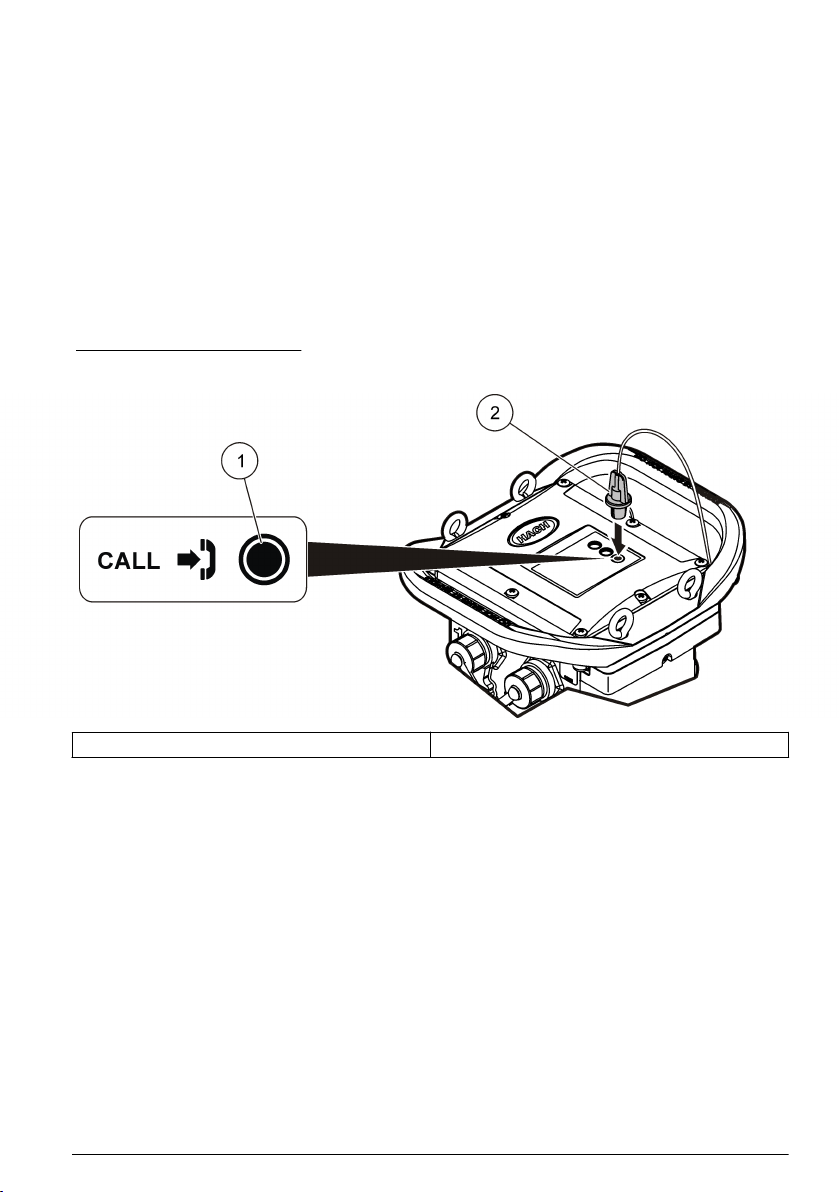
Vérification de la télémesure (option sans fil)
L'utilisateur peut émettre manuellement un appel vers le serveur pour s'assurer que la
communication réseau ne présente pas de défaut.
1. Avant toute installation, veuillez raccorder momentanément l'antenne à l'enregistreur pour tester
l'antenne et la couverture cellulaire sur le site.
2. Faites toucher la clef magnétique et la touche « appel cible émis » (Figure 12). Le voyant DEL du
modem passe au vert.
3. Pendant l'appel (entre 45 et 90 secondes), observez le voyant DEL du modem et attendez qu'un
changement se produise.
• La DEL s'éteint : l'appel au serveur a réussi.
• La DEL clignote en rouge : l'appel au serveur a échoué.
Remarque : En cas d'échec de connexion, consultez la section Dépannage à la page 102 pour plus
d'informations.
Figure 12 Appelez le serveur
1 Touche appel cible 2 Clef magnétique
Vérification de la télémétrie avec FSDATA Desktop
1. Dans FSDATA Desktop, sélectionnez Communications>Modem Diagnostics
(Communications>Diagnostic du modem)
2. Vérifiez que le statut d'enregistrement est local ou itinérance. Si le champ est vide ou si
« Identity » (Identité) s'affiche, la connexion a échoué.
3. Réglez l'antenne pour disposer d'une puissance de signal et d'une qualité optimales.
4. Cliquez sur Call Server (Appeler serveur) pour appeler le réseau.
Une fenêtre contextuelle indique la réussite ou l'échec de l'opération.
Dépannage de la télémétrie
• Vérifiez que le code de vérification du serveur est correct.
• Vérifiez que le numéro de série est enregistré et activé sur le serveur hôte.
• Vérifiez que le modem est activé et que l'adresse IP Hach est correctement saisie.
• Si le problème persiste, contactez l'assistance technique.
Français
97
Page 98

Utilisation de l'option SMS
Configurez le modem FL900 de façon à envoyer ou recevoir des messages SMS (en option).
Reportez-vous à la documentation de FSDATA Desktop pour obtenir davantage d'informations sur la
configuration.
Communication Modbus
Le protocole Modbus peut être utilisé pour communiquer avec cet appareil. Connectez un
périphérique réseau externe, par exemple un automate programmable, au port RS232 de l'appareil
pour lire les données pendant leur enregistrement.
Contactez l'assistance technique pour obtenir davantage d'informations sur les communications
Modbus.
Remarque : Les anciennes données ne peuvent pas être lues avec la communication Modbus.
Configuration de base
Les informations contenues dans ce manuel peuvent servir à créer un programme simple destiné à
l'enregistreur et à étalonner les capteurs. Reportez-vous à la documentation de FSDATA Desktop
pour obtenir davantage d'informations sur les options avancées. Respectez l'ordre de présentation
des sections.
Création d'un programme de base pour l'enregistreur
Il convient d'écrire un programme de base sur l'enregistreur pour spécifier les canaux à enregistrer.
1. Démarrez une session de communication avec l'enregistreur :
a. Ouvrez FSDATA Desktop.
b. Cliquez sur CONNECT (Connecter). La fenêtre Connect to Instrument (Connexion à
l'instrument) s'ouvre.
c. Cliquez sur le bouton FL900.
d. Sélectionnez le port de l'ordinateur sur lequel l'enregistreur est branché (série ou USB), puis
cliquez sur CONNECT (Connecter).
Remarque : Si le message de défaut d'adaptation du capteur s'affiche, sélectionnez « Create new program
based on sensors connected » (Créer un nouveau programme basé sur les capteurs raccordés).
e. Vérifiez que l'état de la connexion indique « Connected » (Connecté).
2. Saisissez les informations dans l'onglet General Settings (Réglages généraux).
Option Description
Identification du site Saisissez un nom unique pour le site.
3. Sélectionnez les chaînes à enregistrer dans la section « Select channels to log » (Sélectionner
les voies à enregistrer) :
a. Développez l'arborescence du groupe de voies de l'enregistreur. La voie « alimentation »
s'affiche systématiquement dans ce groupe. Branchez l'alimentation pour connaître l'état des
piles. Vous pouvez paramétrer une alarme à un seuil spécifique afin d'alerter le gestionnaire
de compte en cas de niveau faible et de l'inviter à venir remplacer les piles pour éviter une
perte de données. Si l'enregistreur est équipé d'un port pour pluviomètre, le canal Rain (Pluie)
s'affiche également. Pour ajouter une voie d'enregistreur dans le Datalog, cochez la case
correspondante en regard du nom de la voie d'enregistrement.
b. Développez l'arborescence de chaque groupe de canaux du Port [1 ](Nom du capteur) pour
visualiser les voies disponibles pour le capteur. Si la case à côté de Logger (Enregistreur) ou
Port[1] est cochée, tous les voies du groupe sont automatiquement sélectionnées.
98
Français
Page 99
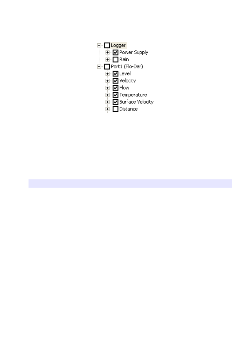
c. Pour ajouter une voie de capteur dans le Datalog, cochez la case correspondante en regard
du nom de voie. Le compteur des voies augmente à chaque fois qu'une nouvelle voie est
sélectionnée.
Remarque : Pour les enregistreurs dotés de plusieurs ports de capteur, le numéro du port est ajouté au
nom de la voie. Par exemple, Velocity 3 correspond au nom de la voie de vitesse pour le port du capteur 3.
4. Pour paramétrer l'intervalle d'enregistrement d'un groupe de canaux :
a. Cliquez sur le nom du groupe de canaux, par exemple Port 1 (Flo-Dar). Les intervalles
d'enregistrement s'affichent.
b. Sélectionnez l'intervalle dans la liste déroulante. Le premier intervalle d'enregistrement
correspond à l'exploitation normale. Le second intervalle d'enregistrement correspond à des
conditions alarme.
Remarque : Vous ne pouvez pas définir un intervalle d'enregistrement pour un canal de capteur en
particulier.
5. Cliquez sur WRITE TO LOGGER (INSCRIRE SUR L'ENREGISTREUR) pour sauvegarder les
paramètres. Un message s'affiche :
Option Description
Attention : toutes les
données seront
perdues. Continuer ?
Configuration de
l'horloge de
l'enregistreur
Toutes les données stockées sur l'enregistreur sont effacées lors de l'inscription
d'un programme sur l'enregistreur. Pour sauvegarder les données, sélectionnez
Non et téléchargez les données à un endroit sûr. Sélectionnez Oui pour
supprimer les données et mettre à jour l'enregistreur avec le nouveau
programme.
Synchronisation avec l'horloge de l'ordinateur : l'enregistreur utilise la date et
l'heure de l'ordinateur. Configuration de l'horloge de l'enregistreur : l'enregistreur
utilise la date et l'heure paramétrées par l'utilisateur. Si l'unité possède un
modem, l'enregistreur utilise automatiquement la date et l'heure du serveur.
Étalonnage du capteur avec l'assistant d'étalonnage
Conditions préalables : L'enregistreur doit être raccordé à l'ordinateur et en ligne pour l'étalonnage.
Il peut être configuré et étalonné à l'aide de l'assistant d'étalonnage.
1. Cliquez sur l'onglet Sensors (Capteurs).
2. Cliquez sur Sensor Port[1] (Port du capteur) (nom du capteur).
3. Cliquez sur le bouton CAL WIZARD (ASSISTANT D'ETAL). La fenêtre Calibration Wizard
(Assistant d'étalonnage) s'ouvre.
Français
99
Page 100
4. Sélectionnez les options sur chaque écran. Lorsque l'écran Calibration Complete (Etalonnage
terminé) s'affiche, cliquez sur FINISH (TERMINE).
5. Cliquez sur WRITE TO LOGGER (INSCRIRE SUR L'ENREGISTREUR) pour sauvegarder les
paramètres. Un message s'affiche :
Option Description
Attention : toutes les
données seront
perdues, continuer ?
Configuration de
l'horloge de
l'enregistreur
Toutes les données stockées sur l'enregistreur sont effacées lors de l'inscription
d'un programme sur l'enregistreur. Pour sauvegarder les données, sélectionnez
Non et téléchargez les données à un endroit sûr. Sélectionnez Oui pour
supprimer toutes les données et mettre à jour l'enregistreur avec le nouveau
programme.
Synchronisation avec l'horloge de l'ordinateur : l'enregistreur utilise la date et
l'heure de l'ordinateur. Configuration de l'horloge de l'enregistreur : l'enregistreur
utilise la date et l'heure paramétrées par l'utilisateur. Si l'unité possède un
modem, l'enregistreur utilise automatiquement la date et l'heure du serveur.
L'installation est terminée. Le témoin d'état doit clignoter en vert si la programmation est correcte.
Installation in situ
A V E RT I S S E M E N T
Dangers multiples. Seul le personnel qualifié doit effectuer les tâches détaillées dans cette section du
document.
Suspension à un câble
A V I S
N'utilisez pas les poignées pour suspendre l'enregistreur. Les poignées ne sont pas conçues pour supporter le
poids de l'enregistreur.
L'enregistreur peut être suspendu à un câble dans le cadre d'une installation dans une zone telle
qu'un trou d'homme.
1. Passez un câble dans les vis à œil situées sur la partie supérieure de l'enregistreur. Reportezvous à la Figure 13.
2. Suspendez le câble à un support solide tel qu'un mousqueton.
100
Français
 Loading...