

Page 1
EC1000 PROCESS
pH/ORP SYSTEM
INSTRUCTION MANUAL
48275-18
© Hach Company, 1994-1997. All rights are reserved. Printed in the U.S.A. al/dk 7/97 3ed
Page 2

2
Page 3

CERTIFICATION
Hach Company certifies this instrument was tested thoroughly, inspected, and found to
meet its published specifications when it was shipped from the factory.
The EC1000 Process pH/ORP System has been tested and is certified as indicated to the
following ins trumentation standards:
Product Safety
Listed by ETL to UL Standard 3101-1 (Listing # H0492805390)
Certified by ETL to CSA Standard C22.2 No. 142 (ETLc Certification # H 0492805390)
Certified by Hach Company to EN 61010-1 (IEC1010-1), supporting test records by
Intertek Testing Services
Immunity
EN 50081-2 (European Generic Immunity Standard) per 89/336/EEC EMC: Supporting
test records Amador (TUV Product Services), certified compliance by Hach Company.
Required Standard/s include:
IEC 801-2 & IEC 1000-4-2 Electro-Static Discharge
IEC 801-3 Radiated RF Electro-Magnetic Fields*
IEC 801-4 Electrical Fast Transients/Burst
Emissions
Emissions per 89/336/EEC EMC: Supporting test records by Intertek Tes ting Services
(ETL), certified compliance by Hach Company.
Required Standard/s include:
EN 55011 (CISPR 11) Emissions, Class B Limits
CANADIAN INTERFERENCE-CAUSING EQUIPMENT REGULATION, IECS-003, Class A
Supporting test records by Intertek Testing Services (ETL), certified compliance by
Hach Company.
This Class A digital apparatus meets all requirements of the Canadian InterferenceCausing Equipment Regulations.
Cet appareil numérique de la classe A respecte toutes les exigences du Règlement sur le
matériel brouilleur du Canada.
FCC PART 15, Class "A" Limits:
Supporting test records by Intertek Testing Services (ETL), certified compliance by
Hach Company.
This device complies wit h Par t 15 o f the F CC Rul e s. Op er at ion is s ubj ec t to th e following
two conditio ns:
(1) this device may not cause harmful interference, and
(2) this device must accept any interference received, including interference that may
cause undesired operation.
* Electromagnetic Radiation of 3 Volts /meter or greater can cause instrument inaccuracy. For complete accuracy details in an
RF environment, refer to the Supplementary Compliance Information in this manual.
3
Page 4

CER TIFICATION, continued
Changes or modifications to this unit not expressly approved by the party responsible for
compliance could void the user’s authority to operate the equipment.
This equipment has been tested and found to comply with the limits for a Class A digital
device, pursuant to Part 15 of the FCC Rules. These limits are designed to provide
reasonable protection against ha rmful interference w hen the equipment is operated in a
commercial environment. This equipment generates, uses, and can radiate radio frequency
energy and, if not ins ta ll ed an d use d in accordance with the instruction manual, may caus e
harmful interference to radio communications. Operation of this equipment in a residential
area is likely to cause harmful interference, in which case the user will be required to
correct the interference at his own expense.
Shielded cables must be used with this unit to ensure compliance with the Class A FCC
limits. Because this instrument operates on and generates radio frequency energy,
interference to radio and television reception may occur. If such interference does occur,
the operator should take the necessary steps to correct the interference. The following
techniques of reducing the interference problems are applied easily.
1. Disconnect power from the EC1000 Controller to verify that it is the source of
the interference.
2. If the EC1000 Controller is plugged into the same outlet as the device with which it is
interfering, try another outlet.
3. Move the EC1000 Controller away from the device receiving the interference.
4. Reposition the receiving antenna for the device receiving the interference.
5. Try combinations of the above.
4
Page 5

TABLE OF CONTENTS
CERTIFICATION ..........................................................................................................................................................3
SPECIFICATIONS ........................................................................................................................................................ 9
SAFETY PRECAUTIONS .......................................................................................................................................... 13
OPERATION .............................................................................................................................................................. 15
SECTION 1 GENERAL INFORMATION ........................................................................................................... 17
1.1 Instrument Description ...........................................................................................................................................17
1.2 EC1000 pH/ORP Controller ...................................................................................................................................17
1.3 Electrolyte Pump .................................................................................................................................................... 17
1.4 Hach One Process pH Electrode ............................................................................................................................ 21
1.4.1 Sodium Error ..............................................................................................................................................21
1.5 Hach One ORP Electrode .......................................................................................................................................21
1.6 Industrial Process pH Electrode .............................................................................................................................22
1.7 Sample Handling System .......................................................................................................................................22
1.7.1 Submersible ................................................................................................................................................ 22
1.7.2 Flow-Thru Cell ...........................................................................................................................................22
1.7.3 In-Line ........................................................................................................................................................ 22
1.8 Principle of Operation ............................................................................................................................................ 23
SECTION 2 OPERATION ......................................................................................................................................25
2.1 Operating the User-Programmable Setup ...............................................................................................................25
2.1.1 Moving Around the Menu .......................................................................................................................... 25
2.1.2 Editing a Setup Value .................................................................................................................................25
2.1.3 Restoring Default Settings .......................................................................................................................... 27
2.2 Setup Menu ............................................................................................................................................................. 28
2.2.1 Alarms ........................................................................................................................................................ 28
2.2.2 Recorder Output ......................................................................................................................................... 29
2.2.3 PID Output ..................................................................................................................................................30
2.2.4 Recorder 2 ................................................................................................................................................... 33
2.2.5 Initial Setup .......................................... ......... ..............................................................................................33
2.2.5.1 Temperature Compensation Setup .................................................................................. .............33
2.2.6 Keylock ....................................................................................................................................................... 35
2.2.7 Reference Solution Timer ...........................................................................................................................36
2.2.8 Warnings ..................................................................................................................................................... 36
2.3 Calibration .............................................................................................................................................................. 37
2.3.1 pH Calibration ............................................................................................................................................38
2.3.1.1 Two-Point Calibration with Auto Recognition of Hach Buffers .................................................39
2.3.1.2 One-Point Grab Sample Calibration ............................................................................................ 40
2.3.1.3 Calibration Procedure Variations ................................................................................................. 40
2.3.1.4 One Point Calibration with a Buffer ............................................................................................ 41
2.3.1.5 Calibration Review .......................................................................................................................41
2.3.2 Temperature Calibration ............................................................................................................................. 41
2.3.3 ORP Calibration/mV Zero .......................................................................................................................... 42
2.3.3.1 Preamp Zero .................................................................................................. ......... ...................... 42
2.3.3.2 ORP Electrode Check ..................................................................................................................43
2.3.3.3 mV Offset ..................................................................................................................................... 43
5
Page 6

TABLE OF CONTENTS, continued
SECTION 3 SERIAL INTERFACE .......................................................................................................................45
3.1 Optional Serial Interface Board ..............................................................................................................................45
3.2 Data Communications Format/Setup ......................................................................................................................45
3.3 Print Format ............................................................................................................................................................45
3.4 Remote Input Commands ............................................... ........................................................................................46
SECTION 4 PID CONTROL ..................................................................................................................................49
4.1 pH Controller Basics ...............................................................................................................................................49
4.2 Instrument Settings .................................................................................................................................................49
4.2.1 Set Point ......................................................................................................................................................49
4.2.2 Dead Band ...................................................................................................................................................49
4.2.3 Preset ........................................................................................................................................................... 49
4.3 Gain .........................................................................................................................................................................49
4.3.1 Reset (Integral) ............................................................................................................................................52
4.3.2 Rate (Derivative) ................................................. ......... ...............................................................................52
4.3.3 Curve ........................................................................................................................................................... 52
INSTALLATION/MAINTENANCE .....................................................................................................................55
SECTION 5 INSTALLATION ...............................................................................................................................57
5.1 Unpacking the Instrument .......................................................................... ........................... ......... ......... ................57
5.2 Industrial Process pH Electrode Preparation ..........................................................................................................57
5.3 Mounting the Controller .........................................................................................................................................57
5.3.1 Panel Mounting ...........................................................................................................................................57
5.3.2 Wall Mounting ............................................................................................................................................59
5.3.3 Pole Mounting .............................................................. ......... ......................................................................59
5.4 Mounting the Pump .................................................................................................................................................59
5.5 Installing the pH/ORP Electrode ............................................................................................................................60
5.5.1 In-Line Electrode Installation .....................................................................................................................62
5.5.2 Submersible Sensor Installation ..................................................................................................................62
5.5.3 Flow-Thru Cell Installation .........................................................................................................................62
5.6 Wiring the Meter .....................................................................................................................................................63
5.6.1 Wire Preparation .........................................................................................................................................64
5.6.2 Power ...........................................................................................................................................................65
5.6.2.1 Line Voltage Selection for Meter ................................................................................................. 66
5.6.3 Alarms .........................................................................................................................................................66
5.6.4 Recorder and Controller ..............................................................................................................................66
5.6.5 Electrode Wiring .........................................................................................................................................67
5.6.6 Electrode Output Connections ....................................................................................................................67
5.7 Pump Wiring ...........................................................................................................................................................68
5.7.1 Line Voltage Selection for Electrolyte Pump .............................................................................................69
SECTION 6 BASIC START-UP ..............................................................................................................................71
6.1 Introduction .............................................................................................................................................................71
6.2.1 Assembling the Electrolyte Line .................................................................................................................71
6.2.2 Connection to the Pump Module .................................................................................................................71
6.2.3 Connection to the pH Electrode ..................................................................................................................71
6.3 Purging the System .................................................................................................................................................72
6.4 Calibration ...............................................................................................................................................................73
SECTION 7 SERIAL INTERFACE .......................................................................................................................75
7.1 Installation ...............................................................................................................................................................75
7.2 RS-232C Interface Configuration ...........................................................................................................................77
7.3 Current Loop Configuration ...................................................................................................................................77
6
Page 7

TABLE OF CONTENTS, continued
SECTION 8 ELECTRODE AND PUMP MAINTENANCE ............................................................................... 81
8.1 Electrode Maintenance ...........................................................................................................................................81
8.1.1 General Electrode Maintenance .................... ......... ..................................................................................... 81
8.1.2 Removing Existing Electrode ..................................................................................................................... 81
8.1.3 Sensor Replacement ................................................................................................................................... 81
8.1.4 Replacing Electrolyte ................................................................................................................................. 82
8.1.5 Crystal Formation in Reference Tube ........................................................................................................84
8.1.6 Purging the System ..................................................................................................................................... 84
8.1.7 Storage and Conditioning ...........................................................................................................................84
8.1.7.1 pH Electrode Storage and Conditioning ......................................................................................84
8.1.7.2 ORP Electrode Storage and Conditioning ....................................................................................84
8.1.7.3 Industrial pH Electrode Shelf Life and Storage ...........................................................................86
8.1.8 pH Electrode Cleaning ................................................................................................................................ 86
8.1.9 ORP Electrode Cleaning .............................................................................................................................87
8.1.10 Industrial pH Electrode Cleaning ...............................................................................................................87
8.2 Pump Maintenance .................................................................................................................................................87
8.2.1 Changing Pump Tubing .............................................................................................................................. 87
8.3 Fuse Replacement ................................................................................................................................................... 88
8.3.1 Meter Fuse Replacement ............................................................................................................................ 88
8.3.2 Pump Fuse Replacement ............................................................................................................................ 90
8.4 Pump Motor Replacement ......................................................................................................................................90
SECTION 9 TROUBLESHOOTING .....................................................................................................................91
9.1 Troubleshooting the EC1000 Controller ................................................................................................................91
9.1.1 Test Diagnostic Menu .................................................................................................................................91
9.1.2 Error Codes .................................................................................................................................................94
9.1.3 System Warnings ........................................................................................................................................ 95
9.2 Troubleshooting the pH Electrode ......................................................................................................................... 96
9.3 Troubleshooting the ORP Electrode ............................................................................................................... 98
SECTION 10 SCHEMATICS ................................................................................................................................. 103
GENERAL INFORMATION ...............................................................................................................................107
REPLACEMENT PARTS ......................................................................................................................................... 109
HOW TO ORDER ......................................................................................................................................................113
REPAIR SERVICE .................................................................................................................................................... 114
APPENDIX A Process pH Electrode Without Internal Preamp ...........................................................................115
APPENDIX B Supplemental Compliance Information ......................................................................................... 117
INDEX ......................................................................................................................................................................... 119
7
Page 8

8
Page 9

SPECIFICATIONS
(Specifications subject to change without notice.)
CONTROLLER SPECIFICATIONS
Ranges: pH: -2 to 16 pH; mV: -2000 to +2000 mV; Temperature: -5 to +105 °C
Accuracy*: pH: ±0.02 pH; mV: ±1.0% of reading, ±35 mV non-calibrated;
Temperature: ±1.5 °C before calibration with electrode, ±0.4 °C after calibration with
electrode.
Resolution: pH: 0.01 pH; mV: 0.1 mV; Temperature: 0.1 °C
Repeatability: pH: ±0.02 pH; mV: ±0.1 mV; Temperature: ±0.2 °C
Temperature Calibration: 1 or 2 point with zero and slope adjustments
Temperature Compensation: -5 to +105 °C for Nearnst equation (auto/manual);
0 to 60 °C for auto buffer recognition
Solution Temperature Correction: Corrected to 25 °C, 0.1 to -0.1 pH units/ °C slope
Operating Temperature: -10 to 60 °C
Storage Temperature: -40 to 60 °C
Humidity Range: 5 to 90% RH non-condensing
Relative mV Adjus tment: The mV zero may be offset to any point in the ±2000 range
Alarms: Alarms 1 and 2: Usable in any of operating modes, (pH/mV/Temperature).
Programmable for either low or high set point alarm. Alarm relays SPDT with contacts
rated at 5A resistive load at 30 Vrms (42.4 Vpk).
Recorder O utput: Isolated 4-20 mA (adjustable to 0-20 mA at 900 ohms)
Controller Output: Proportional, Integral, Derivative. Addi tiona l resi stors can b e used to
provide 0 to 10 V, 0 to 1 V, or 0 to 100 mV outputs.
Input/Output (optional): RS-232C and 20 mA current loop
Signal Average: 0 to 10 seconds
Reading Update: Every 0.4 seconds
Power Requirements: 115/230 Vac (±17%), 50/60 Hz, 8 watts
Controller Enclosure: NEMA 4X/IP66 (rear connections). Suitable for 1/2- inch co nduit.
Wall, panel or pole mounted. For indoor use.
Controller Dimensions: 14.4 cm x 14.4 cm x 12.5 cm deep (5.67" x 5.67" x 4.9" deep).
Panel cutout size: 14 cm x 14 cm (5.5" x 5.5")
* Intermittent Electromagnetic Radiation of 3 Volts per meter or greater may cause measurement inaccuracy. For complete
accuracy details in an RF environment, see the Supplemental Compliance Information in this manual.
9
Page 10

SPECIFICATIONS, continued
Hach One® PROCESS pH SPECIFICATIONS
pH Range: 0 to 14 pH
Accuracy*: pH: ±0.02 pH; Temperature: ±1.5 °C before calibration, ±0.4 °C after
calibration
Repeatability: pH: ±0.02 pH (calibrated at 25 °C and measured at 25 °C);
Temperature: ±0.2 °C
Temperature Range: 0 to 60 °C
Pressure Range: 0 to 35 psi (241 kPa)
Slope: 58 mV± 2 mV/pH units at 28 °C
Reference Element: Ag/AgCl double junction
Electrode Diameter: 28.6 mm (1.125") at tip
Electrode Length: 20.3 cm (8")
Reference Tubing Length: 6.1 m (20 feet) optional 50 feet
Cable Length: 6.1 m (20 feet). Expandable to 1000 feet
Submersion Application: Operational to a depth of 40 feet
Electrical Output: Two 4-20 mA current loops, directly proportional to mV and
temperature
Electrode Housing: Kynar (lower body)/Noryl (polyphenylene oxide) (upper body)
Hach One ORP ELECTRODE SPECIFICATIONS
mV Range: -2000 to 2000 mV
Temperature Range: 0 to 60 °C
Pressure Range: 0 to 35 psi (241 kPa)
Accuracy*: mV: ±10 mV; Temperature: ±1.5 °C before calibration, ±0.4 °C after
calibration
Repeatability: mV: ±2 mV; Temperature: ±0.2 °C
Sensing Element: Platinum disc (99.998% pure)
Reference Element: Ag/AgCl double junction
Reference Potential: 32 ±5 mV vs. SCE
Electrode Diameter: 28.6 mm (1.125") at tip
Electrode Length: 20.3 cm (8")
Reference Tubing Length: 6.1 m (20 feet) optional 50 feet
Cable Length: 6.1 m (20 feet). Expandable to 1000 feet
Submersion Application: Operational to a depth of 40 feet
Electrical Output: Two 4-20 mA current loops, directly proportional to mV and
Temperature
Electrode Housing: Kynar (lower body)/Noryl (polyphenylene oxide) (upper body)
* Calibrated at 25 °C and measured at 25 °C and at atmospheric pressure.
10
Page 11

SPECIFICATIONS, continued
INDUSTRIAL PROCESS pH ELECTRODE SPECIFICATIONS
pH Range: 0 to 12 pH
Reproducibility: ±2% of reading
Temperature and Pressure Range: 0 to 80 °C at 0 to 100 psig; 0 to 100 °C at
ambient pressure
Slope: (pH 4 to pH 7) @ 25 °C: >170 mV
Reference Element: Ag/AgCl
Electrode Diameter: 28.2 mm (1.11") at tip
Electrode Length: 175 mm (6.9")
Electrode Housing: CPVC
PUMP MODULE SPECIFICATIONS
Pressure Range: 0 to 35 psi (241 kPa)
Operating Temperature Range: -20 to 60 °C
Humidity Range: 5 to 90% RH non-condensing
Reagent Usage: Reference solution capacity for a minimum of 1 month of operation
Power Requirements: 115/230 Vac (±17%), 50/60 Hz, 9 VA, 8 watts
Enclosure: NEMA 4X/IP66—Wall mounting, with 1/2-inch NPT for conduit
connections. For indoor use.
MOUNTING KIT SPECIFICATIONS
SUBMERSION APPLICATION
Maximum Submersion Depth: 40 feet (due to restrictions on reference tubing length)
Maximum Velocity at Electrode Tip: 15 km/hour
IN-LINE APPLICATION
Maximum Pressure: 35 psi (241 kPa)
Maximum Flow Rate: 40 L/minute
Minimum Flow Rate: 10 mL/minute
FLOW-THRU CELL APPLICATION
Maximum Flow Rate: 750 mL/m inu te
Minimum Flow Rate: 1 mL/minute
11
Page 12

12
Page 13

SAFETY PRECAUTIONS
Before attempting to unpack , set up, or oper ate this instrument, please read this entire
manual. Pay particula r atte ntion to all wa rnings , cautio ns and note s. F ail ure to do so cou ld
result in serious injury to the operator or damage to the equipment.
To ensure the protection provided by this equipment is not impaired, this equipment
MUST NOT be installed or used in any manner other than that which is specified in
this manual.
Use of Hazard Information
If multiple hazards exist, the signal word corresponding to the greatest hazard shall
be used.
DANGER
Indicates a potentially or imminently hazardous s ituation which, if not avoided, could r esult in
death or serious injury
CAUTION
Indicates a potentially hazardous situation that may result in minor or moderate injury
NOTE
Information that requires special emphasis
Precautionary Labels
Please pay particular attention to labels and tags attached to the instrument. Personal
injury or damage to the instrument could occur if not observed.
This symbol, if noted on the instrument, references the instruction manual for
operational and/or saf et y info rmation.
Section 5.4 Installing the pH/ORP Electrode
Section 5.5 Wiring Meter
Section 5.5.2 Power
Section 5.6 Wiring Pump
Section 7.1 Installation
Section 8.1.7 pH Electrode Cleaning
Section 8.1.8 ORP Electrode Cleaning
Section 8.1.9 Industrial pH Electrode Cleaning
13
Page 14

14
Page 15

OPERATION
WARNING
Handling chemical samples, standards, and reagents can be dangerous. Review the necessary
Material Safety Data Sheets and become familiar with all safety procedures before handling
any chemicals.
ADVERTENCIA
La manipulación de muestras químicas, patrones y reactivos puede ser peligrosa. Antes de
manipular cualquier productor químico, conviene leer las Fichas Técnicas de Seguridad y
familiarizarse con los procedimientos de sugeridad.
ADVERTÊNCIA
A manipulação de amostras, padrões e reagentes químicos pode se r perigosa. Reveja as necessárias
Fichas Técnicas de Segurança do Material e familiarizese com os procedimentos de segurança
antes de manipular quaisquer substãncias químicas.
ATTENTION
La manipulation des écha ntillons c himiqu es, étalo ns et réact ifs p eut êt re dan gereuse . Li re le s fi ches
de données de sécurité des produits nécessaires et se familiariser avec toutes les procédures de
sécurité av ant de manipuler tout produ it chimique.
WARNHINWEIS
Da das Arbeiten mit chemikalischen Proben, Standards, Reagenzien und Abfällen mit Gefahren
verbunden ist, empfiehlt die Hach Company dem Benutzer dieser Produkte dringend, sich vor der
Arbeit mit sicheren Verfahrensweisen und dem richtigen Gebrauch der Chemikalien oder
Biogefahrgut vertraut zu machen und alle entsprechenden Materialsicherheitsdatenblätter
aufmerksam zu lesen.
15
Page 16

16
Page 17

SECTION 1 GENERAL INFORMATION
1.1 Instrument Description
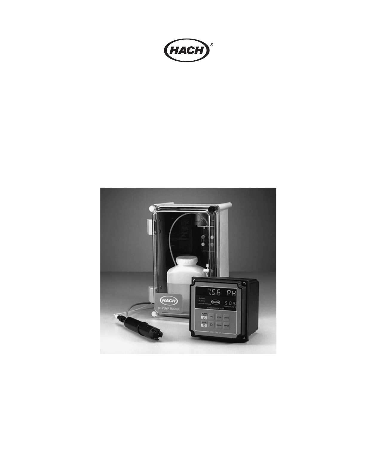
The EC1000 Process pH/ORP Monitoring System consists of the Series EC1000
Controller, a Hach One Pump Module, and a Hach One Process pH or ORP Electrode
assembly. The system monitors a sample stream for its pH value within the range of 0 to
14, or its millivolt potential from -2000 to +2000 mV, and its temperature ranging from
0 to 60 ° C. The sys tem also indica tes when pr eset hi gh and low alarm limits are exceeded,
provides relay closures for external devices, and provides output currents to drive a
recorder and remote process control equipment. Each of these items are described in
detail in the following sections.
1.2 EC1000 pH/ORP Controller
The controller is menu driven with PID capability and is housed in a NEMA 4X/IP66
enclosure (see Figure 1 on page 18). It is set up to receive two current loop inputs from a
pH or ORP probe preamplifier, and to provide a continuous readout of the sample pH or
millivolt value as well as the sample temperature. Output capabilities of the controller
include two 4-20 mA outputs for recording and controlling pumps and optional RS-232C
and 20 mA current loop serial port. Alarm features include user programmable Alarm 1
and Alarm 2 setpoint selections for any one of the operating modes (pH, millivolt, or
temperature) with SPDT relay contacts. The alarm can be a combination of
operating modes:
1.3 Electrolyte Pump
Note: The electrolyte
pump is not used with the
self-pressurized Industrial
Process pH Electrode with
self-pressurized
electrolyte, Cat. No.
48276-00. See Section 1 .6
Industrial Process pH
Electrode.
(Example 1)
Alarm 1-pH High Alarm
Alarm 2-Temperature High Alarm
(Example 2)
Alarm 1-pH Low Alarm
Alarm 2-Temperature Low Alarm
The EC1000 Controller can be mounted up to 1000 feet from the electrode. The pump
module can be mounted up to 50 feet from the electrode.
The pump used on this system is a low pressure linear peristaltic pump, whi ch opera tes up
to 35 psi. The pump is housed in a NEMA 4X enclosure, and allows for a maximum of
50 feet separation from the electrode. It continuously pumps electrolyte through a freeflowing junction in the electrode (500 mL of electrolyte [Cat. No. 24291-49]) lasts
approximately 30 days). The pump module contains a refillable electrolyte reservoir (see
Figure 2 on page 20).
17
Page 18
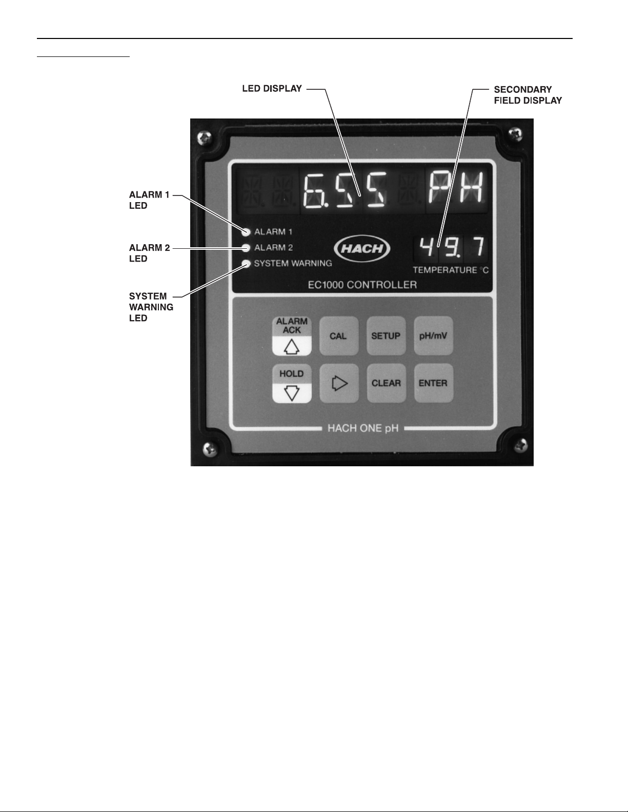
Figure 1 Controller Front Panel
18
Page 19

Table 1 Controller Front Panel
Item Name Function
1 LED Display Main display field. Consists of eight 14-segment alpha-numeric 0.54″ high red LED characters.
During normal operation, this field displays either the pH or mV value (depending on the mode of
operation selected). This field also displays menu messages, edit menu values, and error messages.
See
Figure 1
2 Secondary
Display Field
3 SETUP key This key enters the setup menu. The setup is entered when it is pressed.
4 pH/mV key During normal operation (instrument displaying pH/mV), this key toggles the reading between
5 ENTER key This key, within the menus, either moves a level deeper into the menus, or accepts an edited selection.
6 CLEAR key This key, within the menus, either clears changes in an edit portion of a menu, or backs up one menu
7 RIGHT
ARROW key
8 HOLD/DOWN
ARROW key
The secondary display fiel d consists of three 7-segment numeric 0.3″ high green LED digits.
During normal operation, this field displays temperature. In the setup menu, this field displays
abbreviations to help indicate which branch of the setup menu the operator is in. See
pH and mV. If the instrument is in any of the menus, pressing this key returns the instrument to
normal operation.
leve l. If this i nstrument i s in an ed it portion of a menu s elect ion, and the v alu e is cha nged, th en this k e y
restores the original value. Otherwise, this key causes the menu selection to back up one level; if the
menu is at the top level, this key returns the instrument to normal operation (instrument
displaying pH/mV).
This key, in an edit portion of a menu selection, selects the next digit to the right to edit. The selected
digit flashes. When the instrument is in one of the non-editing portions of the calibration/setup menus,
or in normal operation (instrument displaying pH/mV), this key is not valid; if pressed, an INVALID
message flashes on the main display.
During normal operation (instrument displaying pH/mV), this key functions as a hold. When pressed,
the outputs (alarm relays, recorder, and controller outputs) alternately hold at the current value, or
release to normal operation. When the outputs are held, the first character in the main display
flashes an H. (
appear.
the instrument is in one of the calibration/setup menus, this key scrolls down through the menu
selections. When the instrument is in an edit portion of a menu selection, this key decreases the
selected (flashing) digit.
9 ALARM ACK/
UP ARROW
key
10 CAL key This key enters the calibration menu. From th is menu, the pH electrode, temperature probe, and mV
11 System warning Red LED. Indicates a probe failure or controller malfunction. Refer to Table 4 on page 42 for specific
12 Alarm 2 Red LED. User programmable setpoint alarm. See
13 Alarm 1 Red LED. User programmable setpoint alarm. See
During normal operation (instrument displaying pH/mV), this key functions as an alarm acknowledge.
When pressed, the alarms are alternately disabled or enabled. When the alarms are disabled, the
three alarm indicators flash, and the alarm relays are in the non-alarm state. After the alarms are
disabled for 30 minutes, they automatically enable. When the instrument is in one of the
calibration/set up m en us, this key scrolls up through the me n u selections. When the instrument is in an
edit portion of a menu selection, this key increases the selected (flashing) digit.
offset can be calibrated, and the calibration reviewed.
system warnings tha t appe ar on t he ma in LED dis pla y. For most system warnings , th e use r mu st que ry
the system to determine the warning. See
.
Figure 1.
Note: The H appears only during normal operation; in the menus, the H does not
) After the outputs are in the hold state for 30 minutes, they automatically release. When
Figure 1
.
Figure 1.
Figure 1.
19
Page 20
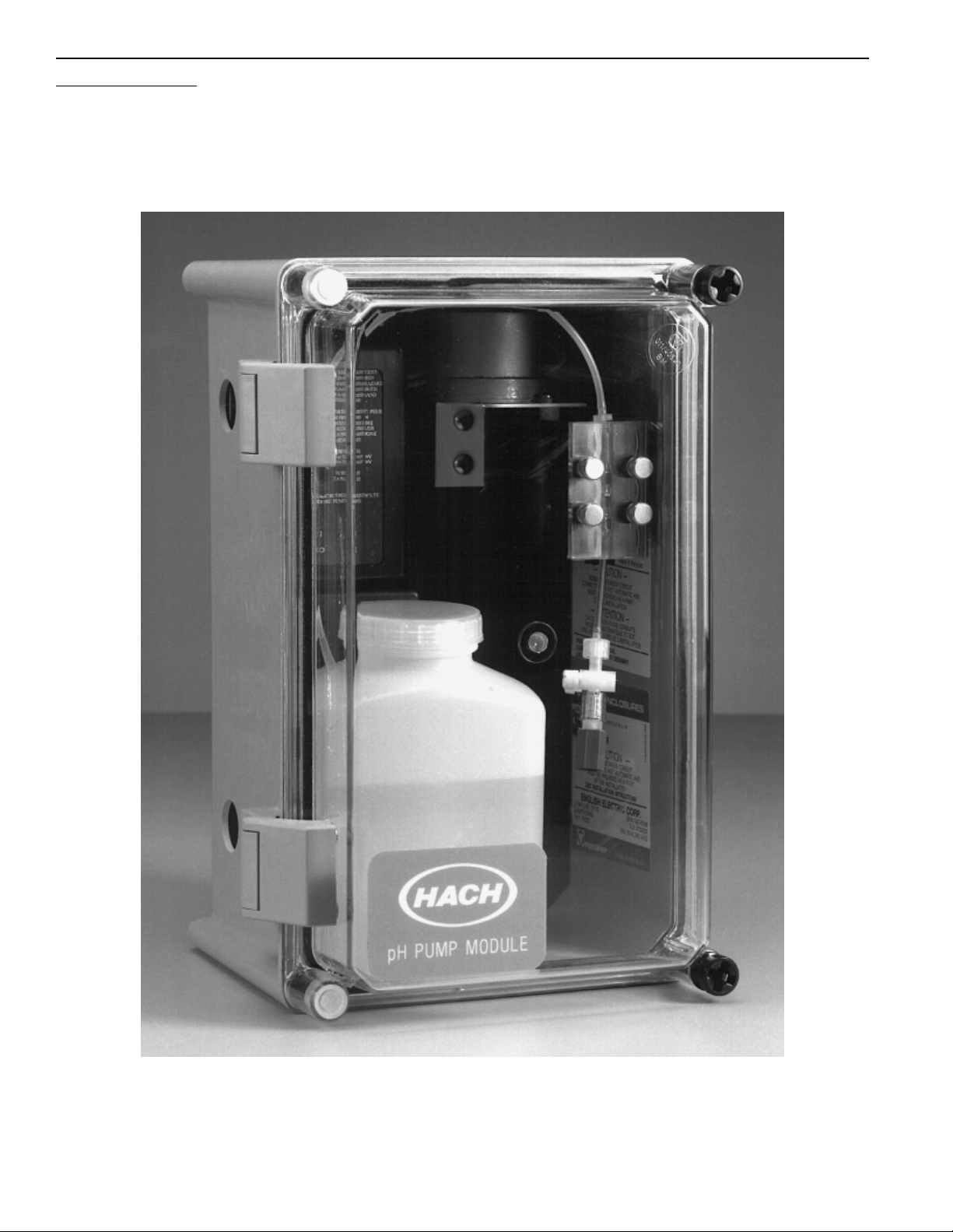
Figure 2 Pump Module
20
Page 21
1.4 Hach One Process pH Electrode
The Hach One pH Electrode features a continuous, free-flowing reference junction to
assure a constant long-lasting reference potential. The electrode contains a replaceable
pH glass sensor (in bulb or flat configuration) a reference half cell, a temperature sensor,
and an internal preamp. The internal preamp produces two current loop signals, one for
mV and the other for temperature. The preamp allows for up to 1000 feet of separation
between the electrode and meter, and is operable up to a depth of 40 feet. The
electrode housing works in any of the sample handling systems described in Section 1.7
Sample Handling System.
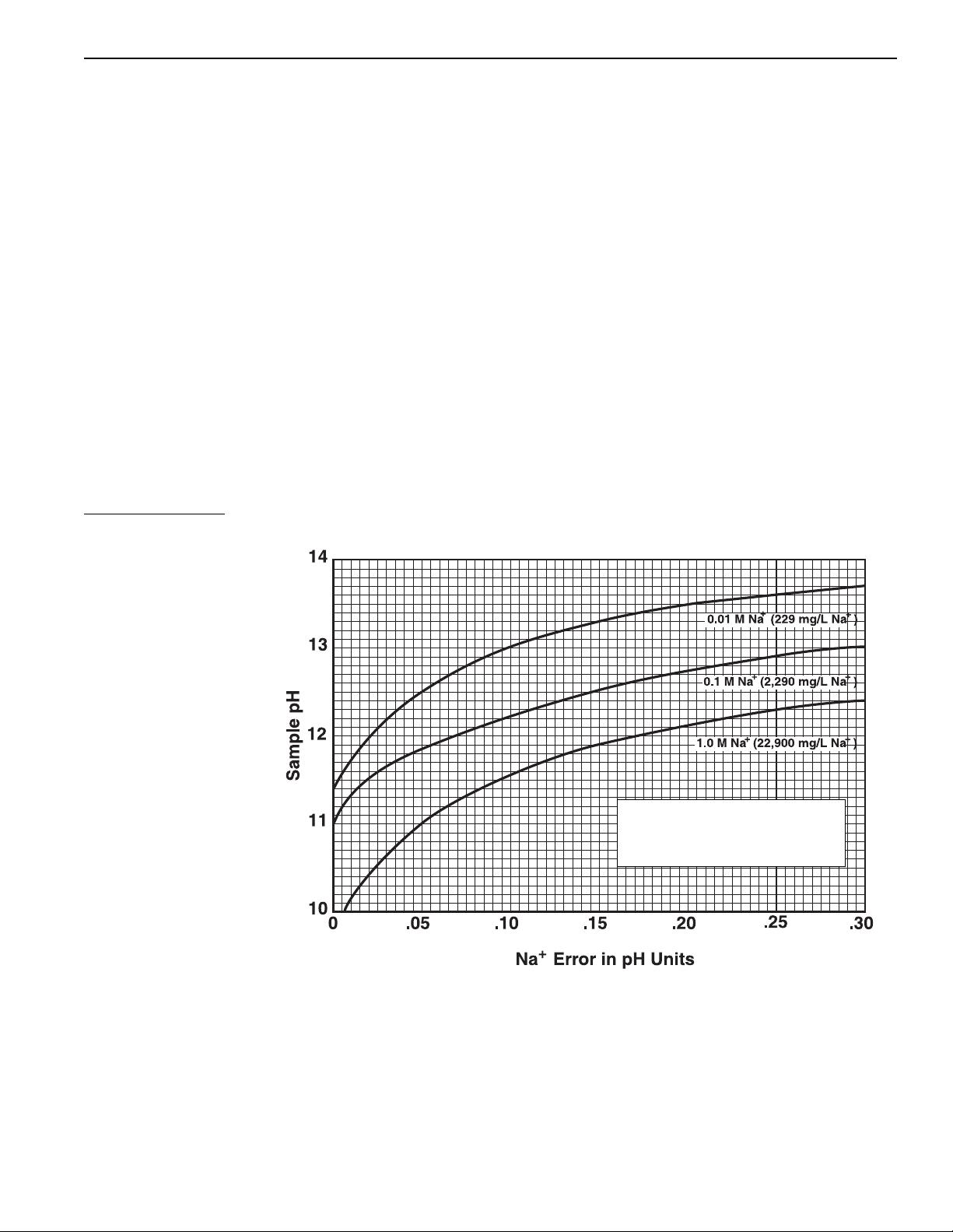
1.4.1 Sodium Error
Acid error is ne gligibl e; neg ati v e sodium er ror , usually pr esent in al kaline s olutions, is lo w
even at pH values as high as 12. To determine the sodium error in pH units, measure the
apparent pH and sodium concentration of the test solution and determine the error from
Figure 3. Locate the point (on the appropriate pH horizontal grid line) representing the
sodium concentration based on the extrapolation between the 229, 2,290, and
22,900 = mg/L Na plots. Add the vertical grid line at that point to the apparent pH meter
reading. For example, a sample that reads pH 12 with a Na+ concentration of 0.5M has a
negative sodium error of approximately 0.12 pH units. Therefore, the actual pH of the
sample is 12.12.
Figure 3 Sodium Ion Error Graph
1.5 Hach One ORP Electrode
The Hach One ORP Electrode also features the continuous, free-flowing reference
junction, a temperature sensor, and a preamp. It is housed in the same electrode body as
the pH flat configured electrode (see Figure 4 on page 22). The replaceable sensor is a
Platinum disc sealed in glass. Select the mV readout for ORP applications.
TYPICAL SODIUM ERROR FOR
HACH ONE COMBINATION pH
ELECTRODE (AT 25 °C)
21
Page 22
Figure 4 Electrodes
1.6 Industrial Process pH Electrode
The Hach Industrial pH Electrode’s unique design does not use an electrolyte pump and
does not have a replaceable sensor. The low-maintenance electrode has self-pressurized
electrolyte and a flat electrode. The electrode features high temperature and pressure
resistance and is designed for traditional applications such as water and wastewater
analysis. The electrode is housed in a CPVC body with a built-in preamplifier and has the
same size and shape to fit all of the mounting configurations described in SECTION 5,
INST ALLATION.
1.7 Sample Handling System
Three sampling techniques can be used with the EC1000 pH/ORP System: submersible,
flow-thru cell, and in-line inst allations. Mounting kits are available fo r the different
applications. Refer to SECTION 5, INSTALLATION for detailed installation information.
1.7.1 Submersible
For the submersible application, mount the electrode to the end of a pipe using the
Submersible Mounting Kit (Cat. No. 46401-00), see Figure 15 on page 61, and place it in
a tank or non-flowing sample.
1.7.2 Flow-Thru Cell
The Flow-Thru Cell provides for atmospheric sampling of the process water, and easy
installation and removal of the electrode. Mounting Kit (Cat. No. 46403-00) is required,
see Figure 16 on page 61.
1.7.3 In-Line
For the in-line application, place the electrode directly in-line with the sample through a
“Tee” pipe fitting using the In-line Mounting Kit (Cat. No. 46402-00), see Figure 15 on
page 61. Pressure reducers may be required if the sample pressure is greater than 35 psig.
22
Page 23
1.8 Principle of Operation
The EC1000 Process pH/ORP System consists of a combination pH or ORP electrode, a
controller, and a reference electrolyte pump (see Figure 5 on page 23). The electrode
consists of a pH or ORP measuring half cell and a double junction reference half cell,
which establish a potential characteristic of the sample. This potential is converted to a
proportional current by a built in preamplifier in order to stabilize the signal for long
distance transmission to the controller. Included in the electrode is a tem perature sensor
whose signal also is stab ilized and sent to the controller to allow for temperature
compensation or temperature correction of the pH/ORP measurement. Separate from the
controller and electrode is a reference electrolyte pump that supplies fresh electrolyte to
the reference half cell. The pumped electrolyte maintains an open reference junction
through a capillary outlet to produce a stable and constant reference potential.
Note: The electrolyte
pump is not used with the
self-pressurized Industrial
Process pH Electrode with
self-pressurized
electrolyte, Cat. No.
48276-00. See Section 1 .6
Industrial Process pH
Electrode.
Figure 5 System Components
As the electrode measures the pH (or mV) of the water source, a signal is transmitted to
the controller. If the pH (or mV) is outside the setpoint range, the controller can transmit
a current output signa l to a reagen t pump (or v alv e) tha t adds reage nt to a mix ing tank. See
Figure 6 on page 24 for details. As the reagent is added to th e water, the value of the pH
(or redox potent ia l) i s adjusted to fall within t he setpoint range. Refer to SECTION 4, PID
CONTROL, for a detailed discussion of this process.
23
Page 24
Figure 6 pH Control Loop
24
Page 25

SECTION 2 OPERATION
2.1 Operating the User-Programmable Setup
The EC1000 Controller is a menu-operated instrument. In the setup menu, each of
the instrument settings are grouped into submenus of common settings. For user
programming, move to the desired setting, and edit the current value. Refer to
Table 18 on page 99, which describes operation of the Diagnostic Test Menu.
2.1.1 Moving Around the Menu
After pressing the SETUP key to enter the menu, use the UP and DOWN ARROW keys to
scroll through the top level menu to the desired entry. Use the
into a submenu (use the
desired settin g is dis played, press t he
and change the value as needed. (Exit the menu at any time by pressing the
Example—checking or changing the ALARM2, SET PoiNT:
CLEAR key to back up to the next higher menu level). Once the
ENTER key to move down
ENTER key to dis play the curr ent v alue o f the setting ,
pH/mV key.)
1. Press
2. Press
SETUP to enter the SETUP menu.
ENTER to move into the ALARMS submenu.
3. Press the
4. Press
ENTER to move into the ALARM2 submenu.
5. Press the
6. Press
ENTER to display the ALARM2 set point.
DOWN ARROW key to scroll to the ALARM2 entry.
DOWN ARROW key to scroll to the SET PoiNT entry.
2.1.2 Editing a Setup Value
Two types of setup data require editing. The first is a number entry such as an alarm set
point. Any value in the set point range can be entered. When the number entry is selected
first, the first digit space displays a flashing
ARROW key alternates between the two signs. Pressing the RIGHT ARROW key moves to
the first digit. This digit flashes indicat ing that it can be edited. Pressing the
key increas es the digit v alue, and pressing the
The remaining digits are changed by repeating this process. When the whole number is
changed to the desired value, press the
during the editing process, the original value is restored by pressing the
+ or – sign character. Pressing the UP or DOWN
UP ARROW
DOWN ARR O W ke y decrease s the digit v alue.
ENTER key to save the new value. At any time
CLEAR key.
25
Page 26
Example—changing ALARM2, SET PoiNT from 16.00 pH to 7.50 pH:
1. First move to the
Around the Menu. Press
2. Press the
3. Press the
4. Press the
5. Press the
6. Press the
7. Press the
RIGHT ARROW key to move the flashing digit to the right.
DOWN ARROW key to change the 1 to 0.
RIGHT ARROW key to move to the next digit.
UP ARROW key to change the 6 to 7.
RIGHT ARROW key to move to the next digit.
UP ARROW key five times to change the 0 to 5.
ALARM2 set point entry as described in Section 2.1.1 Moving
ENTER.
8. Press
ENTER to save the new value.
The second type of setup data is discrete values such as the recorder mode where a pH,
mV, or temperature recorder mode is selected. In this case, the complete entry flashes.
Pressing the
the desired entry, press the
UP or DOWN ARROW key scrolls through the list of settings. After selecting
ENTER key to save the setting.
Example—changing ALARM2, MODE from a PH HI alarm to TEMP LOW alarm:
1. Select ALARM2, MODE as described in Section 2.1.1 Moving Around the Menu.
ENTER.
Press
2. Press the
3. Press
DOWN ARROW key five times to select the TEMP LOW alarm setting.
ENTER to save the new value.
26
Page 27
2.1.3 Restoring Default Settings
To clear all previous settings (not necessary on first time start-up), press CLEAR and
ENTER simultaneously and the D ISPlay TeST appears:
1. Press the
DOWN ARROW key to scroll down through the display test menu to
COLD StaRT.
2. Press
ENTER. This procedure returns all settings to the controller defaults. Table 2
shows all default values for the controller setup menu.
Table 2 Setup Menu Default Value
Menu Options Submenu Default
MODE — PH HI
ALARM1
ALARM2 [same as ALARM1]
RECORDER
CONTROL
INIT SET
SET PNT — 16.00 PH
HYST — 0.10 PH
DLY TIME — 0 SEC
MODE — PH
WINDOW MINIMUM -2.00 PH
— MAXIMUM 16.00 PH
OUT TRIM 0 TRIM 1=4.00
— FS TRIM 1=20.00
MODE — PH
SET PNT — 7.00 PH
DEAD BD — 0.00 PH
PRESET — 50.0%
GAIN — 01.00
RESET — 00.00/HR
RATE — 00.00 MIN
TITR CUR CUR LINEAR+
—POINTS03
OUT TRIM 0 TRIM 1=4.00
— FS TRIM 1=20.00
°C COMP TYPE AUTO TC
— SET PNT 25.0 °C
— SOL TC 0.0 PH
SERIAL I/O BAUD 1200
— PARITY NONE
— DATA BIT 8
—STOP BIT2
— PRT DLY ENABLED
— PRT INTR 00 MINS
OUTPUT 2 — CONTROL
SIG AVG — 1 SEC
27
Page 28
2.2 Setup Menu
2.2.1 Alarms
Two independent programmable setpoint alarms are provided. Each alarm can be set to
operate on pH, mV, or temperature setpoints, and may b e programmab le to be either a high
alarm or a low al ar m. When the programmed setpoints are exceeded, the alarm LED turns
on. The alarm relay actuates when external power is brought to the relays. The instrument
also features programmable alarm hysteresis and delay time. Hysteresis is the difference
between the alarm turn on and turn off values. The delay time provides a delay, from the
time the alarm setpoint is excee ded, bef ore the alar m is actua ted .
The delay time is adjustable from 0 to 30 second s.
To check or program the alarm settings:
SETUP to call up the SETUP menu options.
Press
ENTER to move into the ALARMS submenu.
Press
ENTER to move into the ALARM1 submenu.
Press
The MODE menu is PH high/low, mV high/low, or temperature high/low.
ENTER to select the MODE menu.
Press
PH HI is the default. Scroll through the MODE menu by pressing the
UP ARROW key.
When the desired mode is displayed, press
ENTER to lock in the chosen MODE and move
DOWN ARROW or
to the next ALARM1 submenu.
ENTER. The current SET PoiNT value appears on the display.
Press
To change the value, move the flashing display by pressing the
and increase or decrease the value by pressing the
UP ARROW key.
When the value is set, press
ENTER. The current HYSTeresis appears on the display.
Press
ENTER.
DOWN ARROW key or the
RIGHT ARROW key
The hysteresis is adjustable from 0.01 to 2.0 pH, 0.1 to 100 mV, or 0.1 to 2.0 °C.
To change the value, move the flashing display by pressing the
increase or decrease the value by pressing the
DOWN or UP ARROW key.
RIGHT ARROW key and
ENTER.
Press
ENTER. The current DeLaY TIME will appear on the display. The ALARM1 delay
Press
time is adjustable from 0 to 30 seconds. Reset the delay time by pressing the
ARROW key and increase or decrease the value by pressing the DOWN ARROW key or
UP ARROW key.
the
RIGHT
28
Page 29
Press
ENTER. The DeLaY TIME is locked in, and the display returns to:
CLEAR. The display backs out to:
Press
2.2.2 Recorder Output
Press the
DOWN ARROW key.
The ALARM2 submenu is identical to ALARM1 submenu: mode; set point; hysteresis;
and delay time are all selected identical to ALARM1.
CLEAR and then CLEAR again to back out to the top level of the menu, or press
Press
pH/mV to exit the menu.
An isolated 4-20 mA recorder output is provided. The output also can be adjusted to
0-20 mA, and with the addition of a resistor across the recorder output lines, can be setup
as a 0 to 100 mV, 0 to 1 V, or 0 to 10 V voltage output. See Section 5.6.4 Recorder and
Controller for resistor installation. The recorder can be set to cover any portion of the pH,
mV, or temperature measurement range. The zero and full scale mA output can be
trimmed from the ke yboard so the out put can be calibr ated to e xact ly 4-20 mA, or adjuste d
to match the zero and full scale on the recorder being used.
To check or program the recorder settings, press the
SETUP key to call up the
SETUP menu.
Press the
DOWN ARROW key to scroll to:
This option controls the minimum and maximum outputs shown on the
RECORDER submenu:
ENTER.
Press
PH is the default. The mode options are: PH, MV, or TEMPerature. Select the mode by
pressing the
displayed, press
This option controls minimum and maximum settings on the recorder. Press
Press
Press
ARROW
Press
DOWN ARROW key or the UP ARROW key. When the desired MODE is
ENTER.
ENTER.
ENTER again to display the current MINimum value.
ENTER and change the value by pressing the RIGHT ARROW key and the DOWN
key or the UP ARROW key.
ENTER to advance to:
Press ENTER and change the cur ren t MAXimum value by pressing the RIGHT ARROW key
and the
DOWN ARROW key or the UP ARROW key.
29
Page 30
Press
ENTER to save the new value.
CLEAR. This backs out to the WINDOW menu of the RECORDER submenu.
Press
Next, press the
DOWN ARROW key to advance to:
The function of the OUTput TRIM adjustment is slightly different from the rest of the edit
functions. When the zero (min imum scale ) trim is se lected, th e recor der output is dri ve n to
zero (minimum scal e) , a nd the output value is displ aye d wi th the right hand digit flashing.
If the output is too lo w, pressing a nd hol ding t he
up. When the output is corre ct, re lease th e
DOWN ARROW key to adjust the setting. If a large adjustment is required (e.g., adjusting
the recorder zero from 4 mA to 0 mA), use the
digit to the left. When the
ENTER.
Press
ENTER to display and output the current recorder zero (in terms of mA output).
Press
Press the
Press
Press
Press the
Press
DOWN ARROW key or the UP ARROW key to adjust the output.
ENTER.
ENTER to display and output the current full scale recorder (in terms of mA output).
DOWN ARROW key or the UP ARROW key to adjust the output.
ENTER.
UP/DOWN ARROW keys are used, the output ramps faster.
UP ARROW ke y causes t he outp ut to ra mp
UP ARROW k ey. If the output is too hi gh, use th e
RIGHT ARROW key t o move the flashing
2.2.3 PID Output
CLEAR and then CLEAR again to back out to the top level of the menu or press the
Press
pH/mV key to exit the menu .
A second isolated 4-20 mA output is provided. This output can be selected to be either
a PID controller output or a second recorder output (see Section 2.2.5 Initial Setup, INIT
SET\OUTPUT 2). If the controller output is selected, the following menu entries are
displayed. Refer to SECTION 4 PID CONTROL for a full explanation of these settings.
To check or program the controller settings:
SETUP to call up the SETUP menu:
Press
Press the
Press
The controll er
Press
DOWN ARROW key and then the DOWN ARROW key again to scroll to:
ENTER.
MODE options are pH or mV.
ENTER. Toggle between pH or mV by pressing the DOWN ARROW key. When the
selection is made:
ENTER to save the pH or mV selection and advance to:
Press
30
Page 31

Press
ENTER.
The current v alue for SET P oiNT app ears on the disp lay. Change the v a lue by pr essi ng the
RIGHT ARROW key and the DOWN ARROW key or the UP ARROW key.
ENTER to save the SET PoiNT value and advance to:
Press
ENTER.
Press
The current value for DEAD BanD appears on the display. Change the value by pressing
RIGHT ARROW key and the DOWN ARROW key or the UP ARR OW key.
the
ENTER to save the DEAD BanD value and advance to:
Press
ENTER.
Press
The current setting for the Controller PRESET output appears on the display. Change
the value by pressing the
UPARROW key.
ENTER to save the PRESET value and advance to:
Press
ENTER.
Press
RIGHT ARROW key and the DOWN ARROW key or the
The current setting for the Controller GAIN appears on the display. Change the value by
pressing the
RIGHT ARROW key and the DOWN ARROW key or the UP ARROW key.
ENTER to save the GAIN value and advance to:
Press
ENTER.
Press
The current value for the Controller RESET action appears on the display. Change
the value by pressing the
UPARROW key.
ENTER to save the RESET value and advance to:
Press
ENTER.
Press
The current value for the Controller RATE action appears on the display. Press the
ARROW
Press
Press
key and the DOWN ARROW key or the UP ARROW key to change the value.
ENTER to save the RATE value and advance to:
ENTER.
RIGHT ARROW key and the DOWN ARROW key or the
RIGHT
Toggle between the TITRation CURve mode selections (linear +, linear -, curve) by
pressing the
DOWN ARROW key or the UP ARROW key.
The user must choose linear + or linear - unless a valid set of points is entered. Press
ENTER to save the value and advance to:
ENTER.
Press
Note: The following data
entry sequence is
dependent upon the
number of points selected
above (9).
Select the number of points desired on the TITRation CURve by pressing the
ARROW key and the DOWN ARROW key or the UP ARROW key.
RIGHT
(Range: 3 to 20)
Press ENTER. The display asks for percent of reagent addition (X axis) and pH or mV
value points (Y axis). Percentages and values must be entered in ascending and
descending order with a new entry for each point selected. The controller does not accept
31
Page 32

repeat percentages or values. When all entries are made, return to the Controller MODE
options and select CURVE.
Example—(Assuming PH was selected for the controller MODE)
Press
ENTER.
Select the percent (of reagent addition) for the first point (X axis) by pressing the
ARROW key and the DOWN ARROW key or the UP ARROW key.
ENTER.
Press
Select the PH value by pressing the
UP ARROW key.
RIGHT ARROW key and the DOWN ARROW key or the
RIGHT
The Controller prompts the user to continue entering the percentages and PH values
through nine entries (cor respond ing to number of point s sele cted) . The green LED d ispla y
continues to show which point selection is being made at any time even if the user scrolls
back to the beginning of the sequence.
ENTER then CLEAR followed by the DOWN ARROW key to advance to:
Press
The function of the output trim adjustment is slightly different from the rest of the edit
functions . When the zero (minimum scale) trim is selected, the con troller output is driven
to zero (minimum scale), and the output value is displayed with the right hand digit
flashing. If the output is too low, pressing and holding the
UP ARROW key causes the
output to ramp up.
When the output is correct, release the
DOWN ARROW key. If a large adjustment is requ ired (e.g., adjusting the controller zero
from 4 mA to 0 mA), use the
When the
UP or DOWN ARROW keys are used, the output ram ps faster.
RIGHT ARROW key to move the flashing digit to the left.
UP ARROW key. If the output is too high, use the
ENTER.
Press
ENTER.
Press
This is the trim controller zero setting (in terms of mA output).
Press the
Press
DOWN ARROW key or the UP ARROW key to adjust the output.
ENTER.
32
Page 33

Press
ENTER.
This is the trim controller full scale setting (in terms of mA).
2.2.4 Recorder 2
2.2.5 Initial Setup
Press the
Press
pH/mV key to exit the menu .
DOWN ARROW key or the UP ARROW key to adjust the output.
CLEAR three times. This bac ks out t o the top level of the menu, or you may pr ess th e
The second isolated 4-20 mA output is provided. This output can be selected to be either
a PID controller output or a second recorder output (see INIT SET\OUTPUT 2 in Section
2.2.5 Initial Setup). This menu is the same as the recorder menu (see Section 2.2.2
Recorder Output) except that the mode selection is limited to pH and mV.
The menu entry contains the temperature compensation (C COMP), SERIAL I/O,
OUTPUT 2, and SIGnal AVeraGing setup sub-menus.
The temperature compensation (C COMP) submenu selects between automatic and
manual temperature compensation. When automatic temperature compensation is
selected, the temperature reading from the temperature sensor built into the probe is used
to calculate the pH reading. When the manual temperature compensation is selected, the
value entered into the temperature setpoint is used to calculate the pH reading.
The solution temperature compensation (SOL TC) submenu allows for the compensation
of pH changes to the solution due to temperature. The default setting of 0 pH/°C has no
effect on the reading. For non-zero entries, the instrument subtracts the entry value times
the number of °C the solut ion i s above 25 °C. For ex ample, i f th e entr y is 0.0 10 pH/°C and
the temperature is 50 °C, the instrument will subtract 0.25 pH from the r eading. When the
entry is a non-zero value, an asterisk (*) will appear in the first display location to indicate
the solutio n temperature compensati on is active.
The SERIAL I/O submenu sets up the RS232 C operation. Refer to SECTION 3 SERIAL
INTERFACE for a full e xplanation of these settings. OUTPUT 2 selects between a second
recorder output and a PID controller output.
The SIGnal AVeraGe entry changes the signal averaging to provide a more quiet signal
when the sample is erratic. The range of adjustment is 0 (no signal averaging) to 10
seconds signal average.
To ch eck or program the initial setups refer to the following sections.
2.2.5.1 Temperature Compensation Setup
SETUP to call up the Setup menu:
Press
Press the
Press
DOWN ARROW key three tim es to scroll to:
ENTER to move into the temperature compen sation (C COMP) submenu.
33
Page 34

Press
ENTER.
ENTER to choose the temperature compensation mode (automatic [AUTO TC] or
Press
manual [MAN TC]).
AUTOmatic Temperature Compensation is the default. If MANual Temperature
Compensation is chosen, press the
ENTER.
Press
ENTER. The current SET PoiNT appears on the display.
Press
DOWN ARROW key or the UP ARROW key to toggle to:
Change the SET PoiNT (Range -5.0 to 105.0 °C) by pressing the
followed by the
DOWN ARROW key or the UP ARROW key.
RIGHT ARROW key
Press ENTER to save the value and advance to:
ENTER.
Press
ENTER. The current SOLution Temperature Compensation appears on the display.
Press
Change the SOLution TC (Range: -0.100 pH to +0.100 pH) by pressin g the
key followed by the
ENTER, CLEAR and then the DOWN ARROW key to proceed to the SERIAL inte rface
Press
DOWN ARROW key or the UP ARROW key.
RIGHT ARROW
submenu.
ENTER.
Press
ENTER.
Press
Toggle between baud rates (300, 600, 1200, 2400, 4800, 9600) by pressing the
ARROW
Press
Press
Change the display by pre ssing the
or the
key or the UP ARROW key.
ENTER when the desired rate is selected.
ENTER. The PARITY menu is ODD, EVEN or NONE (default is NONE).
RIGHT ARROW key followed by the DOWN ARROW key
UP ARROW key.
34
DOWN
Page 35

Press
ENTER.
The DATABIT menu is 7 or 8. Select the value by pressing the
UP ARROW key.
ENTER.
Press
The STOPBIT menu is 1 or 2. Select the value by pressing the
UP ARROW key.
ENTER.
Press
ENTER followed by the DOWN ARROW key or the UP ARROW key to toggle between
Press
ENABLED and DISABLED. Press
ENTER.
DOWN ARROW key or the
DOWN ARROW key or the
The PRinT INTerval setting ra nge is 00 to 99 mi nutes. 00 tu rns the print inte rv al of f. Ma ke
a selection by pressing the
UP ARROW key.
ENTER.
Press
RIGHT ARROW key followed by the DOWN ARROW key or the
PRinT LiSTing appears on the display.
ENTER. A listing of the instrument setup is sent to the printer. Then, OK appears on
Press
the display momentarily and the display automatically backs out to BAUD.
2.2.6 Keylock
Note: The initial keyboard
lockout code is 0000, but is
user programmable. Refer
to Section 9.1.1 Test
Diagnostic Menu for
information on
programming the k ey board
lockout code.
CLEAR followed by the DOWN ARROW key. This backs out to:
Press
ENTER followed by the DOWN ARROW key or the UP ARROW key to toggle between
Press
CONTROL and RECORD2 modes.
ENTER.
Press
ENTER.
Press
This displays the pH SIGnal AVeraGe value (00 to 10 seconds), 03 seconds is the default.
Change the display by pres sing th e
UP ARROW key.
or the
ENTER followed by CLEAR to back out to the top le vel menu, or press the pH/mV key
Press
RIGHT ARROW key followed by the DOWN ARROW key
to exit the menu.
T o pre v ent unauthori zed or accident al progra mming changes, a k eyboard lockout or secure
mode is provided using a password. In the locked mode, all program m enus may be
viewed, but no changes to the settings or operations are allowed. If a change is attempted,
the display will flash LOCKED to indicate that the keyboard is locked out.
The keyboard may be locked, unlocked, or temporarily (30 minutes) unlocked.
35
Page 36

To set the keyboard lockout status, press
SETUP to call up the setup menu:
Press the
To call up the keyboard lockout code entry, press
Using the
To key in the keyboard lockout code entry, press
If the code is correct, the sub menu is entered.
Scroll to the desired lockout status by pressing the
UPARROW key.
When the selection is made, press
CLEAR to back out to the top level of the menu or press the pH/mV key to exit
Press
the menu.
2.2.7 Reference Solution Timer
Note: The reference
solution timer is not used
with the non-refillable
Industrial Process pH
Electrode, Cat. No.
48276-00. However,
operators using the
Industrial Electrode are
required to reset the timer
as described.
UP ARROW key three times to scroll to:
ENTER.
UP ARROW and DOWN ARROW keys, enter the lockout code.
ENTER.
DOWN ARROW key or the
ENTER.
2.2.8 Warnings
A referenc e electrolyte timer is provided, which indicates when the reference electrolyte
bottle needs to be filled. Reset the timer each time the electrolyte reservoir is filled. At the
end of 30 days, the timer times out, and a system warning is displayed.
To reset the timer, press
Press the
UP ARROW twice to scroll to:
To reset the timer when adding new electrolyte to the system, press
ENTER.
Press
The display indicat es OK momen tari ly and retu rns t o TiMeR ReSeT . Press
out to the top level menu, or press
SETUP to call up the setup menu.
ENTER.
CLEAR to back
pH/mV to exit the menu.
System warnings ar e pro vided to indi cate p ossibl e probl ems in t he meter and/or elect rode.
If any system warning is pre sent, the system warning LED on the front panel lights. Th e
WARNINGS entry of the setup menu is used to display and clear the warnings. Refer to
36
Page 37

SECTION 9 TROUBLESHOOTING for additional information on the system warnings.
To display or clear the WARNINGS, press
SETUP to call up the setup menu:
Note: The probe errors
and the reference timer
time-out require the cause
of the fault to be corrected
before they will clear.
Press the
Press
Press
UP ARROW key to scroll to:
ENTER.
ENTER. The system displays the Warning Codes s hown in Table 3. Additional det ails
about the warning can be found in Section 9.1.2 Error Codes and Section 9.1.3 System
Warnings. The warning codes appear momentarily followed by CLeaR WaRNing.
Table 3 Warning Codes
CODE MESSAGE CAUSE
E00 EE FAIL EEPROM failure
E01 REF TIME reference timer time-out
E02 SOFT SRT software restart
E03 COLD SRT cold restart
E04 PROBE ER pH probe open
E05 PROBE ER pH probe shorted
E06 PRO BE ER temperature probe open
E07 PROBE ER temperature probe shorted
E08 MARG CAL marginal pH offset
E09 MARG CAL marginal pH gain
E10 MARG CAL marginal temperature offset
E11 MARG CAL marginal temperature gain
E12 PWR FAIL power failure
2.3 Calibration
Press ENTER to CLeaR WaRNings on the display.
Use this menu to calibrate the pH (or ORP) electrode, review the pH calibration, calibrate
the temperature sensor, and adjust the mV offset. The calibration menu is entered by
pressing the CAL ke y. The first disp lay to appe ar is STD 1 , foll o wed by STD 2 (after STD
1 is completed), GRAB SMP, REVIEW, TEMP, and MV ZERO. The user may then scroll
up or down through the first level of the menu to make adjustments to each calibration.
(Note: If the keyboard is locked, only the REVIEW sub menu may be entered.)
37
Page 38

WARNING
To familiarize yo urself
with handling
precautions, dangers and
emergency procedures,
always review the
Material Safety Data
Sheets prior to handling
containers, reservoirs,
and delivery systems that
contain chemical reagents
and standards. Protective
eye wear always is
recommended when
contact with chemicals
is possible.
ADVERTENCIA
Para familiarizarse con las precauciones de manipu lación, los peligros y los prcedimientos
de emergencia, siempre estudie las Hojas de Datos de Seguridad de los Materiales antes de
manipular recipientes, depósitos y sistemas de entrega que contengan reactivos y patrones
químicos. Siempre se recomienda el uso de protectores oculares cuando sea posible el contacto
con productos químicos.
AVISO
Para familiarizar-se com as precauções de manipulação, riscos e procedimentos de emergência,
examine sempre o Folheto de Dados de Segurança antes de manipular os recipientes, tanques e
sistemas de distribuição que contenham reagentes químicos e outros elementos padronizados.
Se recomenda sempre o uso de protetores para olhos, quando possa acontecer contato com os
produtos químicos.
ATTENTION
Pour se familiariser avec les précautions à prendre lors de la manipula tion, les dangers et les
procédures d'urgence, toujours lire les Fiches de Données de Sécurité des Produits avant de
manipuler les récipients, les réservoirs et les tèmes de distribution contenant les réactifs
chimiques et les solutions étalons. Il est toujours recommandé de porter des lunettes de
protection lorsqu'un contact avec les produits chimiques est possible.
WARNHINWEIS
Es wird dringend empfohlen, die Sicherheitsdatenblätter vor der Handhabung von Behältern,
Tanks und Zufuhrsystemen, die chemische Reagenzien und Standardsubstanzen en thalten,
aufmerksam durchzulesen, damit Sie sich mit den beim Umgang mit diesen Chemikalien
notwendigen Vorsichtsma ßnahmen, Risiken und Notfallschutzmaßnahmen vertraut machen,
Es wird empfohlen, in allen Situatione n, in denen mit einem Kontakt mit Chemikalien zu
rechnen ist, eine Schutzbrille zu tragen.
2.3.1 pH Calibration
There are several ways to calibrate the pH electrode. The two recommended methods are
given in the ne xt se ctions. Th e fi rst meth od is a t wo-point calibrati on with b uf f ers. Use this
method on new electrodes and periodically on electrodes already in use.
The frequency of recalibrat ion is deter mined by the ac curacy de sired and th e applicati on in
which the electrode is used.
The second procedure listed is a one-point grab sample calibration. This method provides
for a one-point calibration without removing the electrode from service; perform it
periodically after a two-point calibration. Variations of these two calibration procedures
are give n in Section 2.3.1.3 Calibration Procedure Variations.
Stability Indicator
A stability indicator is activated during the calibration to assist the user in determining a
stable input re ading. The d ecimal point bl inks when t he instr ument de termin es a read ing is
unstable. The decimal point stops blinking when the instrument determines the reading is
stable. Use this indication to decide when to press the
ENTER key, or use your own
judgement. Stability is determined when the mV reading changes at a rate less than
1mV/minute.
Marginal Calibration Indication
During a calibration, a mar ginal message is displa yed if the of fs et is great er than ±100 mV
or if the slope is o utside t he range of 50.6 to 71.2 mV. The system warning ind icator l ights,
but the calibration is accepted.
This warning indicates the calibration is outside the normal range. Repeat the calibration
or clean or replace the electrode.
38
Page 39

Invalid Calibratio n Indication
During a calibration, if the offset is greater than ±300 mV, or if the slope is outside
the range of 44.2 to 89.5 m V, an invalid message is displayed and the calibration is
not accepted.
2.3.1.1 Two-Point Calibration with Auto Recognition of Hach Buffers
The buffers used in a two point calibration should bracket the pH range of the sample.
The following procedure uses the pH 4.01 (Cat. No. 22269-66) and pH 7.00
(Cat. No. 22270-66) Hach buffers supplied with the instrument, but a pH 10.00 Hach
buff er (Cat. No. 22271- 66) can be use d as one of the b uffers. If buffers othe r than the ones
listed above are used, refer to Section 2.3.1.3 Calibration Procedure Variations.
1. Prepare a pH 4.01 Hach Buffer (Cat. No. 22269-66) and a pH 7.00 Hach Buffer
(Cat. No. 22270-66) by dissolving the contents of one powder pillow in 50 mL of
deionized water, and mix.
2. Remove the electrode from the sample solution and clean if needed (see Section 8.1
Electrode Maintenance).
3. Rinse the electrode with deionized water and then place the electrode in prepared pH
4.01 buffer (Cat. No. 22269-66).
4. Press
CAL to call up the main calibration menu.
The display shows:
5. Press
6. Press
7. After the electrode stabilizes (refer to the stability indicator note), press
ENTER. The display shows:
ENTER. The display will show the current pH value.
ENTER to
accept this calibration point.
8. Rinse the electrode with deionized wat er the n pl ace the ele ctr ode in prepared pH 7.00
buffer solution (Cat. No. 22270-66).
9. Press
10. Press
ENTER. The display shows:
ENTER. The display will show the current pH value.
11. After the electrode stabilizes (refer to the stability indicator note), press
accept this calibration point.
12. Press
pH/mV to return the meter to normal operations.
13. Rinse the electrode with deionized water and return it to the sample.
39
ENTER to
Page 40

2.3.1.2 One-Point Grab Sample Calibration
Note: When Solution
Temperature
Compensation is
operational (non-zero, see
Section 2.2.5 Initial Setup)
the current pH v alu e sa v ed
and displayed in Step 3 is
the actual pH of the
process sol ution at the
process temperature. For
best accuracy, the lab
sample reading should be
taken at the same
temperature as the
process sample reading.
This method is used to do a one point (offset) pH calibration using a grab sample
comparison of the process solution measured on a calibrated laboratory or portable pH
meter. This calibration is not as accurate as the two point calibration because it only
corrects the of fset, and does not adjust the slope. A speci al feature of thi s calibrati on is that
the pH electrode readings are saved at the time the grab sample is taken (see Step 3). This
allows for an accurate calibr ation even if the pH of the process stream changes during the
time used to measure the sample on a laboratory meter.
1. Press
2. Press the
CAL to call up the main calibration menu. The display show s:
DOWN ARROW key to proceed to:
3. Take a sample of the process solution and then press
pressed, the current pH value is saved and displayed on the readout with the first
digit flashing.
4. Measure the pH of the sample on a calibrated lab meter.
5. Edit the value on the display to match the lab reading by pressing the
key and the
6. Press
7. Press
ENTER to accept the calibration.
pH/mV to return the m et er t o n orm al op erations. The pH reading may be different
from the value just entered. This occurs if the pH of the process stream changes from
the time the grab sample was taken in Step 3. For example, if the pH of the process
stream increases by 0.15 pH during the time between Step 3 and Step 6, the current
reading should be 0.15 pH higher than the value entered in Step 5.
2.3.1.3 Calibration Proce dure Vari ati ons
ENTER. When the enter key is
RIGHT ARROW
DOWN ARROW key or the UP ARROW key.
Note: The Auto recognition
function is valid only when
using the following Hach
buffers: pH 4.01, pH 7.00,
or pH 10.00. If buffers
other than those listed are
used, the buffer value must
be entered.
Manual Entry o f Buffer Value
Use two buffers in the range of 0 to 14 pH that are at least 1 pH unit apart for calibration.
You may use one auto and one manually entered buffer or two manually entered buffers
for calibrations. The order in which the buffers are used has no effect on the calibration.
To use manual entry of buffer value(s), replace Step 6 and/or Step 10 with the
followingprocedure.
1. Press the
2. Press
DOWN ARROW key to scroll to the manual entry. The display shows:
ENTER. The readout is an edit display with a pH value such a 6.97 PH. (The
last value used is displayed.) The lower display shows the current temperature of
the buffer.
3. After the temperature reading stabilizes, use the temperature reading and the chart
provided with the pH buffer to determine the actual buffer value.
40
Page 41

4. Edit the value on the display by pressing the
ARROW key or the UP ARROW key so the display matches the buffer value.
RIGHT ARROW key and the DOWN
5. Press
ENTER. The readout displays the current pH value.
2.3.1.4 One Point Calibration with a Buffer
To calibrate the instrument with one buffer and a one point calibration, follow the
procedure for a two point calibration with buffers, omitting Steps 8-11.
2.3.1.5 Calibration Review
The calibration review menu entry is used to track the performance of the electrode. The
menu entries are OFFSET, SLOPE, STD 1, and STD 2. The of f set i s a me asur e o f t he mV
reading when the electrode is at pH 7. The ideal offset is 0 mV. The slope is a measure of
the mV/pH at 25 °C, with the ideal slope being 58 mV/pH. For new electrodes, the offset
should be 0 ±35 mV, and the slope should be 58 ±2 mV. For normal calibration, the meter
accepts an offset in the range of ±100 mV and a slope in the range of 50.6 to 71.2 mV.
STD 1 and STD 2 entries recall the standard(s) used for the last calibration.
2.3.2 Temperature Calibration
The uncalibrated accuracy of the temperature sensor is ±1.5 °C and temperature
calibration is normally not required. If greater accuracy is required, use the following
procedure for either a one point or a two point calibration. The calibration temperature
should be near the anticipated operating point for a one point calibration, or bracket the
anticipated operating range and be at least 10 °C apart for a two point calibration.
1. Remove the electrode from the sample cell.
2. Place the electrode in a sample of known temperature.
s 3. Press
4. Press the
5. Press
6. Press
The readout is an edit display with a temperature value s uch as 0.0 °C. (The last value
displayed is used.)
7. Edit the value on the display by pressing the
key or the
8. Press
CAL to call up the main calibration menu. The display show s:
UP ARROW key twice. The display shows:
ENTER. The display shows:
ENTER. The display will show:
RIGHT ARROW key and DOWN ARROW
UP ARROW key so that the display matches the sample temperature.
ENTER. The readout displays the current temperature of the sample.
9. After the electrode stabilizes (refer to the stability indicator note in Section 2.3
Calibration), press
ENTER to accept the calibration point. If this is a one point
calibration, omit Steps 10-13.
41
Page 42

Note: The temperature
difference between the
two samples must be at
least 10 °C.
10. Move the electrode to a sample at a different known temperature.
11. Press
ENTER. The readout is an edit display with a temperature value such as 60.0 °C.
(The value displayed is the last value used.)
12. Edit the value on the display to match the temperature of the sample by pressing the
RIGHT ARROW key and the DOWN ARROW key or the UP ARROW key.
13. Press
14. After the electrode stabilizes (refer to the stability indicator note in Section 2.3
Calibration), press
15. Press the
2.3.3 ORP Calibration/mV Zero
Note: Although the Light’s
Solution Ampule contains
enough solution f or se v eral
calibrations, reusing the
solution is not suggested
due to potential
contamination. Hach
Company recommends
discarding the remaining
solution after use.
The mV zero is used for ORP measurements. This entry allows for ORP calibrations and
for the mV reading to be offset to a desired value.
To calibrate the ORP electrode, the offset of the internal preamp must be zeroed, and then
the electrode must be standardized in a solution of known redox potential. Hach offers
Light’s Solution (Cat. No. 26125-20) as an ORP standard in 20-mL glass ampules sealed
under argon. Or, you may prepare your own solutions as described in Table 4.
Standard
Solution
Light’s
Solution
Zobell’s
Solution
* SHE = Standard Hydrogen Electrode.
** The deviation from 32.0 mV versus SCE is due to conventional junction potentials produced by the high
ionic strength of Light’s Solution.
ENTER. The readout displays the current temperature measurement.
ENTER to accept this calibration point.
pH/mV key to return the meter to normal operations.
Table 4 Preparation of Redox Standard Solutions
Hach ORP
Electrode
446** mV 430 mV +675 mV 39.21 g ferrous ammonium sulfate,
215 mV 183 mV +428 mV 1.4080 g potassium ferrocyanide,
Pt Electrode
vs. SCE
Pt Electrode
vs. SHE*
Weight per 1000 mL Solution
at 25 °C
Fe (NH4)2 (SO4)2 • 6H2O
48.22 g ferric ammonium sulfate,
Fe (NH4) (SO4)2 • 12H2O
56.2 mL sulfuric acid, sp gr 1.84
Fe (CN)6 • 3H2O
K
4
1.0975 g po tassium ferricya nide,
Fe (CN)
K
3
7.4555 g po tassium chloride, KCI
6
2.3.3.1 Preamp Zero
1. Connect one end (pin) of the ORP Shorting lead to the reference pin connector at the
top of the electrode. Touch the other end directly to the platinum disc of the ORP
Sensor, see Figure 5 on page 23.
2. Press
3. Press the
4. Press the
CAL to call-up the main calibration menu. The display shows:
UP ARROW key. The display shows:
ENTER key. The readout is an edit display such as 0.0 mV. (The value
displayed is the last value used).
5. Edit the value on the display to read 0.0 by pressing the
DOWN ARROW key or the UP ARROW key.
RIGHT ARROW key and the
42
Page 43

6. Keeping the ORP shorting lead in con tact with the platinum disc, wait for a stable
reading and then press the
ENTER key twice.
7. Press the
2.3.3.2 ORP Electrode Check
To ensure the ORP electrode is functioning correctly, it is necessary to check its potential
in a solution of known redox potential. The nominal potential of the Hach EC1000 ORP
electrode in Light’s and ZoBell’s solution are given in Table 4. Also see Table 5.
The electrode should rea d within ±10 mV of the nominal value. The potent ial of the Hach
EC1000 reference electrode is 32 ±5 mV versus SCE (Saturated Calomel Electrode) in
saturated KCl Solution.
pH/mV key to return the meter to normal operations. Remove the ORP
shorting lead.
Table 5 Potential of Zobell’s Solution as a Function of Temperature
(vs. Standard Hydrogen Electrode)
Temperature (°C) EV Temperature (°C) EV
1 0.481 16 0.448
2 0.479 17 0.446
3 0.476 18 0.443
4 0.474 19 0.441
5 0.472 20 0.439
6 0.470 21 0.437
7 0.468 22 0.435
8 0.465 23 0.432
9 0.463 24 0.430
10 0.461 25 0.428
11 0.459 26 0.426
12 0.457 27 0.424
13 0.454 28 0.421
14 0.452 29 0.419
15 0.450 30 0.417
2.3.3.3 mV Offset
Once it has been determined that the ORP electrode is functioning properly, a mV offset
can be performed so that the display reads values which are more familiar to the operator.
For example, if it is known that a pr ocess must be held at a set point versus SCE, then the
mV zero can be set at 430 mV when the elect rode is place d into Li ght’s Solution. Now the
display will read mV versus SCE.
1. Remove the electrode from the sample cell.
2. Place the electrode in a sample with a known mV potential.
3. Press CAL to call up the main calibration menu. The display shows:
4. Press the
5. Press
UP ARROW key. The display shows:
ENTER. The readout is an edit display with a millivolt value such as 0.0 mV.
(The last value displayed is u sed.)
43
Page 44

6. Edit the value on the display to match the mV potential of the sample by pressing the
RIGHT ARROW key and the DOWN ARROW key or the UP ARROW key.
7. Press
ENTER. The readout displays the current mV value.
8. After the electrode stabilizes (refer to the stability indicator note in Section 2.3
Calibration), press
9. Press
pH/mV to return the meter to normal operations.
ENTER to accept this calibration point.
44
Page 45

SECTION 3 SERIAL INTERFACE
3.1 Optional Serial Interface Board
A serial interface board (Cat. No. 46326-00) is available as a user-installed option for the
pH/ORP Meter. The board enables the analyz er t o be connected to a printer or a computer
to provide a permanent record of pH/mV levels and the occurrence of any alarm
conditions. Connection with a computer allows the computer to compile and store sample
pH/mV data and to control analyzer programming and operation from a remote location.
The interface board was designed primarily to permit direct connection of the analyzer
data output to an external printer. Interface with an external computer requires computer
programming to permit communication with and control of the analyzer. Due to the
variety of computer equipment and programming formats in use, this manual is written
for an operator knowledgeable about digital interface protocols and programming
requirements. The interface board can be set for two serial interface configurations:
standard RS-232C format or a current loop format.
3.2 Data Communications Format/Setup
Data communication format selections of baud rate, parity, word length and stop bits, are
set in the serial [I /O] submen u of the set up menu. Refer to Section 2.2.5 Initial Setup. The
factory default settings are: 1200 baud, no parity, 8 bit word length, 2 stop bits.
3.3 Print Format
The serial I/O operates without handshake, therefore care must be taken to prevent loss
of data. During data transmission from the instrument, each character is sent at 53 ms
intervals. At the end of ea ch line a 1. 5 second del ay is added. Th is delay is r equired fo r use
with many printers that have a one line buffer. The delay allows the printer time to print
the line bef ore the next line is started. If the printer delay is not requi red, it is disabled in
the serial I/O submenu of the setup menu. On the receive data, no delays are required
between characters, but the receive buffer only holds one line. Therefore if more than one
command is being sent, the response from the first command must be completed before
the next command is sent.
The data print format is set for a 40-column print width. On power-up, (unless print
interval is set to 0) or on command, a data header is output to the printer (Figure 7).
The data header contains information about the analyzer setup. The data header may be
printed at any time by selecting the print listings.
See Figure 7 for:
• a system warning (*W9*11*)
• normal sample measurement (pH, MV, TEMP)
• an activated alarm lockout (*ALO*)
• setpoint alarms (*A1*)
• manual temperature compensation indicator (M)
• making a user calibration (pH OFFSET CAL)
45
Page 46

Figure 7 Analyzer Printout
KEYBOARD LOCKED
ALARM 1 = 105.0 C LOW
ALARM 1 HYST = 0.5 C
ALARM 1 DELAY = 00 SECS
ALARM 2 = 16.00 PH HIGH
ALARM 2 HYST = 0.50 PH
ALARM 2 DELAY = 00 SECS
SIGNAL AVERAGE = 03 SECS
AUTO TEMPERATURE COMP
PRINT EVERY 00 MINS
REC MINIMUM = -2.00 PH
REC MAXIMUM = 16.00 PH
CONTROL SET PT = 7.00 PH
CONTROL PRESET = 50.0 %
CONTROL GAIN = 0.00
CONTROL RESET = 0.00 /HR
CONTROL RATE = 0.00 MIN
PH MV TEMP ALARMS
6.35 69.7 49.0
6.34 70.5 48.9 *A1*
6.89 6.5 25.0M *A1*
6.80 11.6 25.0M *W5*7*11*
6.80 11.6 25.0M *W7*8*
6.80 11.6 25.0M
6.81 11.3 5.0M *ALO*
6.81 11.3 25.0M *ALO*
6.35 69.4 49.0 *W8*
pH OFFSET CAL
7.00 27.8 25.0 *W6*11*
>16.00 <-2000.0 25.0 *A2*W9*11*
7.00 27.9 >105.0 *W11*
3.4 Remote Input Commands
Commands sent to the analyzer fr om a computer must be format ted as an ASCII chara cter
string in uppercase or lowercase letters. Spaces are allowed, but not required. All
commands sta rt with a three character string . If additional information is needed to set a
value, an equal sign “=” is entered, followed by the data desired. The command is
completed by sending a CR (OD Hex) [Example: To recall the alarm 1 setpoint:
A1S<CR>; to set alarm1 setpoint to 7.5: A1S=7.5<CR>]. Refer to Table 6 for a complete
command list.
All commands except co ld star t (C ST) gener ate a res pons e message indica ting ac cep tance
or rejection of the command from the analyzer. If the command is rejected, the response
is “[?.”
Response messages from the instrument are preceded by a steering character, which the
computer program can test to determine if the line is a response message or if the line is a
routine printout. The steering character is an ASCII left bracket “[”(5B Hex).
Note: If the print interval is
set to zero (disabled), then
the only outputs ge nerat ed
are response messages.
Programs (Basic, C, etc.) must be written for the computer to transmit the proper
command strings to the analy zer via the inte rface.
46
Page 47

Table 6 RS-232 Remote Commands
Code Function Response
GENERAL SETUP
CST Do a cold start Prints setup
SCD Set calibration defaults OK
SAV <=(0 to 10)> Recall or set signal average Value (on recall); or OK (on
set)
RCV Recall current measurement values Prints cur rent values
KLO Toggles keyboard lockout status and responds with the
new status
TCM<=(AUTO, MAN)> Recall or set temperature compensation mode Value (on recall); OK (on set)
TCS<=(-5 TO 105)> Recall or set temperatur e compensation setpoint Value (on recall); OK (on set)
RSR Reference solution timer reset OK
RECORDER
RMD <=(PH, MV, TEMP)> Recall or set recorder mode Value (on recall); OK (on set)
RMX <= -2 to 16 for pH,
±2000 for mV,
-5 to 105 for temperature>
RMN <= -2 to16 for pH,
±2000 for mV,
-5 to 105 for temperature>
RTX <=(-2132 TO 2132)> Move recorder trim maximum count by indicated amount OK
RTN <=(-2132 to 2132)> Move recorder trim minimum count by indicated amount OK
Recall or set maximum value setpoint for current recorder
type
Recall or set minimum value setpoint for current
recorder type
CONTROLLER
Locked or Unlocked
Value (on recall); OK (on set)
Value (on recall); OK (on set)
CMD <=(pH, mV) > Recall or set controller mode Value (on recall); OK (on set)
CSP <=(-2 to 16 for pH ,
±2000 for mV)>
CDB <=(0 to 2 for pH,
0 to 100 for mV)>
CPR <=(0 to 100)> Recall or set controller preset Value (on recall); OK (on set)
CGN <=(0 to 99.99)> Recall or set controller gain Value (on recall); OK (on set)
CRS <=(0.00 to 99.99)> Recall or set controller reset value Value (on recall); OK (on set)
CRT <=(0.00 to 99.99)> Recall or set controller rate value Value (on recall); OK (on set)
CTX <=(-2132 to 2132)> Move controller trim maximum count by indicated amount OK
CTN =(-2132 to 2132) Move controller trim minimum count by indicated amount OK
A1M <= (PH HIGH, PH LOW,
MV HIGH, MV LOW,
TEMP HIGH, TEMP LOW)
A1S <=(-2 to 16 for pH,
±2000 for mV,
-5.0 to 105.0 for temp)>
A1H <=(0.01 to 2 for pH,
1 to 100 for mV,
0.1 to 2 for temp)>
A1D <=(0 to 30 )> Recall or set alarm 1 delay time Value (on recall); OK (on set)
A2M <=(PH HIGH, PH LOW,
MV HIGH, MV LOW,
TEMP HIGH, TEMP/LOW)>
Recall or set controller setpoint Value (on recall); OK (on set)
Recall or set controller dead band Value (on recall); OK (on set)
ALARMS
Recall or set alarm 1 mode Value (on recall); OK (on set)
Recall or set alarm 1 setpoint for current alarm type Value (on recall); OK (on set)
Recall or set alarm hysteresis for current alarm type Value (on recall); OK (on set)
Recall or set alarm 2 mode Value (on recall); OK (on set)
47
Page 48

Table 6 RS-232 Remote Commands (continued)
Code Function Response
ALARMS (continued)
A2S <=(-2 to 16 for pH,
±2000 for mV,
-5.0 to 105.0 for temp)>
A2H <=(0.01 to 2 for pH,
1 to 100 for mV, 0.1 to 2
for temp)>
A2D <=(0 to 30 )> Recall or set alarm 2 delay time Value (on recall); OK (on set)
ALO Toggles alarm lockout status and responses with the
RWN Recall system warnings Print warnings followed by OK
CWN Clears syst em warning OK
LST List Setup Print Setup
PIV <=(0 to 99 )> Recall or set print interval Value (on recall); OK (on set)
Recall or set alarm 2 setpoint for current alarm type Value (on recall); OK (on set)
Recall or set alarm hysteresis for current alarm mode Value (on recall); OK (on set)
Locked or Unlocked
new status
PRINTER
48
Page 49

SECTION 4 PID CONTROL
4.1 pH Controller Basics
A simple pH control loop is shown in Figure 6 on page 24. This same configuration and
procedure can be applied to ORP applications. There are endless variations to this basic
loop, but the main elements of the loop are shown. The loop operates as follows: The pH
meter measures the value of the pH in the effluent, and, if the pH is different from the
setpoint, the controller actuates the reagent pump (or valve) that adds reagent to a mixing
tank. The added reagent adjusts the value of pH.
The physical layout of the loop, the sizing of the pump (valve), type of mixing tank, and
location of the pH electrodes all have a major effect on the ultimate performance of the
loop, after the cont rolle r is tun ed for opt i mal perf ormance. The largest single performance
factor is the delay time around the loop. This includes the response time of the
electrode/meter, time required to deliver the reagent to the process water, time required for
the reagent to mix with and rea ct with the process water, and the time required to deliver
the completely mixed water to the electrode. If the delay times are too long or the mixing
is not complete, the control will be poor regardless of how well the controller is tuned.
The Process pH/ORP Meter uses a PID control algorithm. PID stands for proportional,
integral (reset), derivative (rate) control. Each of the instrument settings (in the
CONTROL menu), along with their affects on the control loop, are described below.
4.2 Instrument Settings
4.2.1 Set Point
This is the value of pH (mV) that is desired.
4.2.2 Dead Band
This is the window around the set point where the controller takes no action (any input in
this window is considered to be at the set point).
4.2.3 Preset
This is the value of the proportional component of the controller when the input is at the
set point.
Example 1—
In an application where the pH of the process water is always above the set point, only an
acid feed is required. In this case, the preset is typically set to 0%. When the pH of the
water is at or below the set point, the controller output is at zero and there is no chemical
feed (this assumes the feed pump is set up to deliver no output for a zero input and
maximum output for a ful l scal e input). When the pH of the water goes abo ve the set point,
the controller output goes up, increasing the chemical feed, which drives the pH of the
water down.
Example 2—
4.3 Gain
In an application where the pH of the process water can be either above or below the set
point, both an acid and caustic feed is required.
Refer to Figure 8 for a diagram of the controller output response (proportional only) to a
step change on the input. The gain setting determines the instrument’s sensitivity to an
error (the difference between the set point and the input pH). If the gain is doubled, then
the output signal doubles for a given error signal. For a proportional only controller
(integral an d deriv ati v e settings of f), th e steady state error decreas es with higher ga ins, b ut,
49
Page 50

if the gain is set too hi gh, the l oop goe s into oscil lation. Be cau se the proport ional output is
the error times the gain, there must be an error term (unless the required output is the same
as the preset value).
Figure 8 PID Controller Output Response
50
Page 51

Example—
Refer to Figure 9. In the three examples, it is assumed that the signal to the pump requires
about 35% to bring the pH value to the set point. In Figure 8a, the preset is at 0%, and the
gain is at 10. For these conditions, the steady state error is about
In Figure 8b, the gain is increased to 100, which reduces the error to about
In Figure 8c, the gain is reduc ed back to 10, b ut the prese t is set to 30%. Having the preset
set closer to the required output reduces steady state error to about
0.09pH
The number 18 in the preceding equations represents the controller pH range of
-2 to 16 pH.
By using the integral action the steady state error is reduced to zero.
Figure 9 PID Controller Set Point/Error Measurement
0.63pH
0.063pH
0.35 0–
-------------------- -
10
0.35 0–
-------------------- -
100
0.35 0.30–
---------------------------- -
10
.
18pH()=
18pH()=
.
18pH()=
.
51
Page 52

4.3.1 Reset (Integral)
4.3.2 Rate (Derivative)
4.3.3 Curve
Please see Figure 8 for a diagram of the controller output response (integral only) to a step
change on the input. The integral action is used to drive the loop so that there is zero long
term error . F or e xample, on a propor tional co ntroller where the steady state pH is too hi gh,
the integral component of the output starts ramping up until the increased chemical feed
brings the pH down to the set point. The higher the setting, the faster the loop reaches
steady state, but it should not be set faster than the delay times in t he l oop. I f th e set t ing is
too high, the loop goes i nto oscillation (this generally tends to be a slower oscillation than
that caused by a gai n o r der i v at ive setting that is too hi gh). T he inte gra l actio n is turned off
by setting it to zero.
Please see Figure 8 for a diagram of the controller output response (derivative only) to a
step change on the input. The derivative action reacts to rate of change of the input and
attempts to counter fast changes. The derivative action is turned off by setting it to zero.
The curve mode entry has three settings (linear+, linear-, curve). For most applications
either linear+ or line ar - is used. Line ar+ is sele cted when th e control pump is se t up so that
an increasing controller output signal causes the pH to increase. Linear- is selected when
the control pump is set up so that an increasing controller output signal causes the pH to
decrease.
The use of the curve selection can improve the control loop if the characteristics of the
sample are repeatable over time. For o ptimal control, the loop gain (con troller gain x
process gain) should remain constant, but for most samples the process gain changes over
the pH range.
Please see Figure 10. The process g ain (def i ned as : ∆ pH /∆ % reagent addit ion) at po int 1
through point 5 is r eprese nte d by the s lope of th e line b etween e ach point a nd th e setpo int.
For this example, the slope of the line (process gain) changes considerably depending on
the pH of the sample. If this curve is entered into the EC1000, the controller can
compensate for the change in process gain to keep the loop gain constant.
To implement the titration curve, take a sample of the process water , and t it ra te wi th t he
reagent (acid and/or base u sed i n the process). Record the pH value (Figure 11). Enter this
curve into the instrument as percent r eagent addi tion vs. pH. Th e f inal step, after en tering the
titration points, is to go bac k to t he c urve mode entry, and se lec t t he cu rve setting.
52
Page 53

Figure 10 PID pH Process Gain
0
REAGENT DEMAND %
4
0
REAGENT DEMAND %
14
13
12
11
10
9
8
pH
7
6
5
4
3
2
1
10 20
The process gain seen by the controller is the slope of a line between
the setpoint and the pH measurement on the titration curve.
Setpoint
30 40 50 60 70 80 90 10
3
2
1
5
Figure 11 PID Titration Curve
pH
16
15
14
13
12
11
10
9
8
7
6
5
4
3
2
1
0
-1
-2
0 2040608010
53
Page 54

54
Page 55

INSTALLATION/MAINTENANCE
Some of the following manual sections contain warning
labels and require special attention.
Read and follow all warning instructions carefully to avoid
personal injury and damage to the instrument. Only
qualified personnel should conduct maintenance
procedures on this instrument.
55
Page 56

56
Page 57

SECTION 5 INSTALLATION
5.1 Unpacking the Instrument
When removing the instruments from their shipping containers, inspect all units for any
damage that may have occurred during shipment. The containers include the EC1000
Controller, Pump Module, Electrode, Instruction Manual, installation kits for the
Controller and Pump Module, Pump Module maintenance kit, and electrolyte
(see REPLACEMENT PARTS on page 109). If damage is evident, or if the shipment is
incomplete, customers outside the U.S.A. should contact their local Hach Distributor.
Customers inside the U.S.A. should contact Customer Service in Loveland, Colorado.
Call toll-free 1-800-227-4224.
5.2 Industrial Process pH Electrode Preparation
Remove the el ec tr ode f ro m t he box a nd c are fully remove the tape and protec tive cap from
the sensing end. Retain th e prot ective cap for electrode storage. If salt crysta ls are pr ese nt,
remove them by placi ng the sen sing end o f the elect rode unde r a curr ent of w arm ta p water
until the crystals dissolve. Keep the quick disconnect fitting dry. It is important to avoid
touching the internal area of the quick disconnect fitting. Contamination, such as oils and
salts from bare hands, can form a leakage path affecting the high impedance required
between the electrode and the controller.
5.3 Mounting the Controller
The controller is designed for panel, wall or pole mounting. All methods use a Mounting
Bracket (Cat. No. 43646-00). For dimensions and other mounting information see
Figure 12 on page 58 and Figure 13 on page 59.
5.3.1 Panel Mounting
Cut the panel befor e insert ing the mete r. The panel cutout is to be 5 .50"x 5.5 0" ±0. 05". Fo r
panel mountin g, remove the two mounting brackets, insert the meter int o the panel, and
reattach the mounting brackets. See Figure 12 on page 58. Insert screws
(Cat. No. 5617-11) through mounting bracket inserts, and adjust for panel thickness.
57
Page 58

Figure 12 Controller Installation/Panel Mount
58
Page 59

5.3.2 Wall Mounting
For wall mounting, remove the two mounting brackets, reverse the brackets, and reattach
to the meter, see Figure 13. Secure the meter to the wall using screws or bolts
(not supplied) through the clearance holes in the mounting brackets.
5.3.3 Pole Mounting
For pole mou nting, re mov e one of the mounting br acket s. Open cla mp (Cat. No. 43277-00 )
and pass clamp end without screw around pole and through slot in mounting bracket.
Attach both ends of clam p and secure tightly to pole, see Figure 13. Reatta ch bracket to
the meter.
Figure 13 Controller Installation/Wall and Pole Mount
5.4 Mounting the Pump
Note: The pump modu le is
not used with the Industri al
pH Electrode.
The Pump Module can be placed on a bench top or wall mounted. To wall mount,
mounting blocks are secur ed to the fo ur re ar corne rs of the enclosu re. The four blocks and
screws are supplied in the wall mounting kit (Cat. No. 44247-00). The mounting blocks
should be positioned as shown in Figure 14 on page 60 and fastened with the four screws
provided. Open the front cover of the pump module and insert one screw in each of the
four corner holes. Turn the screws into the mounting blocks using a long-shafted
screwdriver.
Screws or bolts to mount the pump module are not provided. Refer to Section 6.2.1
Assembling the Electrolyte Line, Section 6.2.2 Connection to the Pump Module, and
Section 6.2.3 Connection to the pH Electrode for plumbing the electrolyte tubing.
The pump is housed in a NEMA 4X/IP66 rat ed encl osure . The
fitting is installed in a standard ½″ conduit hole an d also can b e replace d with a ½″ cond uit
fitting for har d conduit. Thi s is recommended to pre vent da mage to the
supply tubing. The maximum tubi ng length betw een the elec trode and the pump is 50 feet.
The standard configuration includes 20 feet of electrolyte supply tubing. For installations
that require 20 to 50 feet of tubing, order Hach Cat. No. 46399-00.
59
1
/
″ OD tubing strain relief
16
1
/
″ OD electrolyte
16
Page 60

Figure 14 Pump Installation
5.5 Installing the pH/ORP Electrode
Note: Improve stability in
high purity water by
grounding the solution
near the electrode.
Different mounting equipment is available for the three configurations for mounting the
electrode. The ele ctrode ca n be conf igured as an i n-line uni t insta lled in a full pipe line (se e
Figure 15) or on the end of a dip tube as a submersible unit in a tank or other vessel. The
electrode also can be placed in a flow-thru cell for applications of flow with very little
pressure (see Figure 16). Maximum pressure is 35 psi for in-line installation or 40 feet of
immersion depth for submersible installation. Do not deviate orientation more than
90 degrees from vertical for the three types of installation. The configuration used
determines whether the bushing or collar is threaded with the reference tube and cable
prior to installation. Maximum temperature for the electrode is 60 °C.
60
Page 61

Figure 15 Installing the pH/ORP Electrode
Figure 16 Flow-Thru Cell
61
Page 62

5.5.1 In-Line Electrode Installation
A 1-½″ NPT fitting is required in line, which must be filled with the sample stream (see
Figure 15 on page 61). Orienting the electrode between 45 to 70° from the vertical helps
prevent air bubbles from interrupting the signal. Install the mounting collar into the 1-½″
fitting using Teflon tape or thread compound on the male threads. Place the compression
nut over the top of the electrode.
Note: Avoid electrode
damage and erroneous
measurements by closely
adhering to the maximum
pressure and temperature
specifications, see
SPECIFICATIONS on
page 9.
Do not use pipe compound or Teflon tape on the compressi on nut. Slip the o-ring over the
bottom of the electrode. Connect the reference tubing to the top of the electrode, with a
compression nut and ferr ule ( see Figur e 25 on page 85 , Detail A). Connect the cable to the
electrode through the quick disconnect coupling on the top of the electrode.
The electrode is now ready for installation into the mounting collar, but must be purged
and calibrated before operation (see SECTION 6 BASIC START-UP). When installing the
compression nut into the mounting collar, hand-tighten only.
For optimal pe rfor mance , orient the ref erenc e out let of the ele ctrod e downstream from the
glass sensor wit h re spect to flow direction. The electr ode ch eck valve and stem are l ocated
directly over the reference outlet.
5.5.2 Submersible Sensor Installation
Submersible sensors are typically installed on the end of a 1-½″ ID pipe having a 1-½″
NPT fitting (see Figure 15 on page 61). Install the mounting collar into the 1-½″ NPT
fitting using Teflon tape or pipe compound on the male threads. Run the electrode cable
and reference tubing throug h the mount in g coll ar and p ipe. Sli de the o-ri ng o ve r the t op of
the electrode against the flange. Connect the reference tubing to the top of the electrode
with a compression nut and ferr ule (se e F igure 25 on page 85, Detail A). Connect the ca ble
to the electrode through the quick disconnect coupling on the top of the electrode. Place
the compression nut over the electrode and hand tighten into the mounting collar. (Do not
use Teflon tape or pipe compound on the compression nut ). The ele ctr ode must be purged
and calibrated before operation (see SECTION 6 BASIC START-UP).
5.5.3 Flow-Thru Cell Installation
The flow-thru cell is mounted to the wall using screws or bolts (not provided) through the
two ¼-inch mountin g holes (see F igure 16 on page 61). The inlet, lo cated o n the botto m of
the cell, is suitable for ¼-inch flexible tubing.
The inlet fitting can be removed an d replaced with a ¼-inch NPT fitt ing suitable for rigid
tubing. The outlet, located on the side of the cell, is suitable for ½-inch flexible tubing.
The outlet fit ting can be r emo ve d and repla ced wit h a ½-i nch NPT f i tti ng suit able for ri gid
tubing. The electrode is inserted from the top of the cell. The electrode must be wired,
purged, and calibrated before operation (see SECTION 6 BASIC START-UP).
62
Page 63

5.6 Wiring the Meter
WARNING
Wiring connected in this
box must be rated at least
300Vrms/600Vpk.
ADVERTENCIA
Los cables de senalizacion conectados a esta caja deben tener una clasificacion de por lo menos
300Vrms/600Vpk.
ADVISO
A hacao dw sinal conectada nesta caixa deve ter classificaco de pelo menos 300Vrms/600Vpk.
ATTENTION
Le câblage de signalisation raccorde dans ce boîtier doit convenir pour une tension nominal e
d'au moins 300Vrms/600Vpk.
WARNHINWEIS
Die diesem kasten angeschlossene signal verdrahtung mub nit mindestens 300Vrms/600Vpk
bemessen sein.
The meter wires are r outed thr ough three ½-inch co nduit f itti ngs loc ated on th e back of th e
meter (see Figure 17). The left conduit hole (as viewed from the front of the meter) is for
alarm connections, the center conduit hole is for power connections and the right conduit
hole is for electrode, recorder, controller, and SIO connections. The left and right conduit
holes have molde d-i n knoc k outs, which must be removed if used. To maintain the NEMA
4X and IP66 ratings of the enclosure, the conduit fitting (not supplied) must be a sealing
type. To make the wire connections refer to Section 5.6.1 Wire Preparation. Remove the
front panel of the meter by re movi ng the four corn er scre ws. Disconn ect the e xisti ng wires
from the front panel by unplugging the connector(s) (see Figure 18 on page 64).
Remove the wire shield. Unplug the connector from the circuit board on the front panel,
and hook up the wires. Replace the wire shield , routin g the wires through t he notche s, and
verifying that the shield wire stays under the wire shield. Plug the connectors into the
circuit board, and replace the front panel of the meter.
Figure 17 Controller Inside Back Cover
63
Page 64

Figure 18 Controller Circuit Board
5.6.1 Wire Preparation
Because low voltages (voltages <30Vrms) and primary voltage (115/230 Vac) are not
separable within the controller enclosure, it is necessary that all customer wiring be 300V
or more to assure adequate levels of insulation protection of low voltage wires from high
voltage circuits. Additionall y, the recommended cable for signal wires (electrode,
recorder, controller, and SIO) is 22 AWG twisted pair shielded cable, which assures
compliance with RF immunity and emissions standards.
The alarm cable can be unshielded cable sized according to the lo ad being used. Prepare
the cables as follows: Strip the outer jacket back 7 inches. Cut the shield wire to a length of
3 inches.
64
Page 65

5.6.2 Power
Table 7 Power Cord Color Code
North American IEC
Line Conductor Black Brown
Neutral White Blue
Ground Conductor Green Green with Yellow Stripe
WARNING
All electrical connections
should be made by a
qualified technician to
assure compliance to
all applicable electrical
codes. To meet UL, CSA
and other applicable
instrument safet y
standards, an external
power disconnect switch
must be installed. This
power disconnect switch
should be located near the
instrument. Wiri ng for the
recorder and serial
interface connections
must be routed separately
from the alarm
connections and AC
power line for safe
operation. Separate
½-inch conduit openings
are provided for this
purpose. Shielded cables
may be required if cables
are not routed in
grounded metal conduit to
ensure emission's
compliance.
ADVERTENCIA
Todas las conexiones eléctricas deben ser realizadas por un técnico capacitado para asegurar el
cuplimiento con todos los códigos eléctricos. Para cumplir con las normas UL, CSA y otras
normas de seguridad aplicables a los instrumentos, debe instalarse un interruptor de
desconexión de la alimentación externa. El mismo debe estar ubicado cerca del instrumento. El
cableado para la grabadora y las conexiones de interfaz en serie deben encaminarse de manera
separada de las conexiones de la alarma y la línea de alimentación de CA para un
funcionamiento seguro. Se proporcionan aberturas separadas de conductos de ½ pulgada para
este propósito. Podrían requerirse cables protegidos si los mismos no están encaminados en
conductos metálicos conectados a tierra, para asegurar el cumplimiento con la emisión.
AVISO
Todas as conexões elétricas devem ser realizadas por técnico qualificado para garantir o
cumprimento de todas as normas elétricas aplicáveis. P ara cumprir as especificações UL, C SA e
outras medidas de segur ança padrãoap licáveis ao instrumen to, deve ser i nstalado um in terruptor
externo para desliga r a energia. Est e interr uptor desl igador da energia dev erá ser col ocado perto
do instrumento. As instalações elétricas das conexões do registro e as entrefásicas em série
deverão estar separadas das conexões do alarme e da linha de CA, para que sua operação seja
segura. Eletrodu tos de pass agem de ½ polega da são f ornecid os em separ ado par a este pr opósi to.
Caso os cabos não forem traçados por eletrodutos metálicos com ligação à t er ra , para garantir a
conformidade co m as normas de irra diação, poderá ser necessário o uso de ca bos blindados.
ATTENTION
Tous les branchements électriques doivent être effectués par un technicien qualifié, afin
d'assurer le respect de toutes les normes électriques applicables. Pour répondre aux normes UL,
CSA et à d'autres normes applicables concernant la sécurité de l'appareil, il est nécessaire
d'installer un interrup teur externe permettant de couper l'alimentation électrique. Cet
interrupteur doit être situé près de l'appareil. Le câblage pour l'enregistreur et les branchements
de l'interface série doivent être tirés séparément des bra nchemen ts de l'alarme et du fil
d'alimentation électrique, afin d'assurer un fonctionnement sans risque. Des orifices de conduits
de ½ pouce séparés sont fournis à cet effet. Des câbles blindés peuvent être nécessaires si les
câbles ne sont pas tirés dans un conduit métallique relié à la terre, afin de respecter les normes
sur les émissions électro-magnétiques.
WARNHINWEIS
Um zu gewährleisten, daß alle elektris chen Anschlüsse den VDE-Vorschriften und
gegebenenfalls den Zusatzvorschriften der zuständigen Elektrizitätswerke sowie anderen
zutreffenden Sicherheitsnormen entsprechen, dürfen diese Anschlüsse nur von geschultem
F achpersonal hergestellt werden. Um allen zutreffenden Sicherheitsbestimmungen für das Gerät
zu entsprechen, muß ein externer Netztrennschalter installiert werden. Dieser Netztrennschalter
sollte sich in unmittelbarer Nähe des Gerätes befinden. Die Verdrahtung für den Anschluß an
die Registriergerät-Schnittstellen s owie an die se riellen Schnittstellen ist aus
Betriebssicherheitsgründen getrennt von den Warnanschlüssen und der WS-Netzleitung zu
führen. Zu diesem Zweck sind separate Rohröffnungen mit einem Durchmesser von 0,5 Zoll
vorgesehen. Um zu gewährleisten, daß die Emmissionsbestimmungen erfüllt werden, sind
eventuell Abschirmkabel erforderlich, insofern di Kabel nicht in geerdeten Metallrohren
geführt werden.
65
Page 66

The recommended size of the power supply leads is 18AWG, but can be in the range of
12AWG to 18AWG. The wires are routed through the center conduit hole and are hooked
up to the power connector (see Figure 17 on page 63). The power leads are twisted
together to fit in the compartment formed by the wire shield and the back of the case.
5.6.2.1 Line Voltage Selection for Meter
Note: Misapplication of AC
line power to this
instrument can cause
damage to the instrument.
Prior to connection, verify
that the Volt Select Switch
is set for the proper AC
line requirement.
This instrument is f actory set a nd properl y fused for 115 Vac line requirements. To conver t
the instrument for 230 Vac line requirements, proceed as follows:
1. Rotate the indicator slot on the Volt Select Switch to the 230 V position (s ee Figure 18
on page 64).
2. Remove the 0.2A fuses, and replace them with appropriate type 0.1A fuses (refer to
Section 8.3 Fuse Replacement).
5.6.3 Alarms
The alarm relays have unpowered contacts, and the power to operate the load is supplied
by the user. Fi gu re 19 shows a typical wiring configuration. The wires must be sized
according to the load used. For the maximum 5A load, the wires must be a minimum
of 16 AWG.
The wires are routed through the left conduit hole (see Figure 17 on page 63), and are
hooked up to J5 on the front panel (see Figure 18 on page 64). Maximum voltage is
30Vrms (42.4V pk).
Figure 19 Typical Wiring Configuration
5.6.4 Recorder and Controller
The recorder and controller connections are isolated 4-20 mA outputs and should be
connected with twisted pair shielded cable. The shield wire should be connected at the
instrument end only.
66
Page 67

Note: Use a twisted-pair,
shielded cable. U se of
non-shielded cables may
result in radio wave
emission levels higher than
permitted under the
compliance
regulations listed.
5.6.5 Electrode Wiring
The wires are routed through the right conduit hole (see Figure 17 on page 63) and are
hooked up to J1 and J3 on the front panel (see Figure 18 on page 64). The shield wire is
connected inside the back cover (see Figure 17 on page 63). For voltage output, a resistor
across the recorder input lines is needed. The resistor must be connected only if the
recorder requires a 0 to 10 V, 0 to 1 V, or 0 to 100 mV input. The resistor must be
connected at the recorder input terminals, not at the EC1000 output terminals. Ordinary
5% or 10% tolerance resistors are acceptable, as the controller’s output can be trimmed to
provide the proper voltage. Use a 1/4 watt resistor for a 0 to 10 V signal. Use a 1/8 watt
resistor for 0 to 1 V or 0 to 100 mV signals. Use a 500 ohm resistor for 0 to 10 V signal.
Use a 50 ohm resis tor for 0 to 1 V sign al. Use a 5 ohm res istor f or 0 to 100 mV s ignal. The
controller’s 4 mA output must be trimmed to 0 mA.
Refer to Section 2.2.2 Recorder Output.
Be sure the power is turned off to the controller. The electrode cable has a quick
disconnect coupling on one end which attaches to the electrode body. Route the electrode
cable into the controller through the right conduit hole (see Figure 17 on page 63). There
are four color coded wires and a shield wire inside the electrode cable. The color coded
wires are connected to the only four-pin removable plug in the controller J2 connector
as follows:
Note: The shield must be
connected to provide a
stable electrical signal
between the electrode
and the meter.
white--pin 1 / green--pi n 2 / black--pin 3 / red--pin 4
The shield wire is connected inside the back cover (see Figure 17 on page 63). The
electrode cable can be wired directly to an optional junction box that is permanently
wired to the controller. The junction box has eight blank terminals located behind the
inside cover.
5.6.6 Electrode Output Connections
IMPORTANT NOTE: Turn off power to the pH/ORP Analyzer before disconnecting the
electrode at the quick disconnect. Failure to do so may result in permanent electrode damage.
Note: The shield must be
connected to provide a
stable electrical signal
between the electrode
and the meter.
If the measuring instrument is within 6 m (20 feet) of the electrode, the output cable is
supplied for the final connection. If the distance is greater than 6 m (20 feet), use the four
conductor cable, Cat. No. 46894-00, and junction box, Cat. No. 47122-00. Both cables
contain four conductors and a quick disconnect fitting. Refer to Section 5.6.5 Electrode
Wiring and to the table below for additional wiring information.
ELECTRODE PREAMPLIFIER
White pin #1
Green pin #2
Black pin #3
Red pin #4
67
Page 68

5.7 Pump Wiring
WARNING
All electrical connections
should be made by a
qualified technician to
assure compliance to all
applicable electrical
codes. To meet UL, CSA
and other applicable
instrument safet y
standards, an external
power disconnect switch
must be installed. This
power disconnect switch
should be located near the
instrument. Wiri ng for the
recorder and serial
interface connections
must be routed separately
from the alarm
connections and AC
power line for safe
operation. Separate ½inch conduit openings are
provided for this purpose.
Shielded cables may be
required if cables are not
routed in grounded metal
conduit to ensure
emission's compliance.
ADVERTENCIA
Todas las conexiones eléctricas deben ser realizadas por un técnico capacitado para asegurar el
cuplimiento con todos los códigos eléctricos. Para cumplir con las normas UL, CSA y otras
normas de seguridad aplicables a los instrumentos, debe instalarse un interruptor de
desconexión de la alimentación externa. El mismo debe estar ubicado cerca del instrumento.
El cableado para la grabadora y las conexiones de interfaz en serie deben encaminarse de
manera separada de las conexiones de la alarma y la línea de alimentación de CA para un
funcionamiento seguro. Se proporcionan aberturas separadas de conductos de ½ pulgada para
este propósito. Podrían requerirse cables protegidos si los mismos no están encaminados en
conductos metálicos conectados a tierra, para asegurar el cumplimiento con la emisión.
AVISO
Todas as conexões elétricas devem ser realizadas por técnico qualificado para garantir o
cumprimento de todas as normas elétricas aplicáveis. Para cumprir as especificações UL, CSA
e outras medidas de segurança padrão aplicáveis ao instrumento, deve ser instalado um
interruptor externo para desli ga r a energia. Este interruptor desligador da energia deverá ser
colocado perto d o instru mento. As insta lações elétr icas das conexões do regi stro e as entref ásicas
em série deverão estar separadas das conexões do alarme e da linha de CA, para que sua
operação seja segura.Eletrodutos de passagem de ½ polegada são fornecidos em separado para
este propósito. Caso os cabos não forem traçados por eletrodutos metálicos com ligação à terra,
para garantir a conformidade com as normas de irradiação, poderá ser necessário o uso de
cabos blindados.
ATTENTION
Tous les branchements électriques doivent être effectués par un technicien qualifié, afin
d'assurer le respect de toutes les normes électriques applicables. Pour répondre aux normes UL,
CSA età d'autres normes applicables concernant lasécurité de l'appareil, il est nécessaire
d'installer un interrup teur externe permettant de couper l'alimentation électrique. Cet
interrupteur doit être situé près de l'appareil. Le câblage pour l'enregistreur et les branchements
de l'interface série doivent être tirés séparément des bra nchemen ts de l'alarme et du fil
d'alimentation électrique, afin d'assurer un fonctionnement sans risque. Des orifices de conduits
de ½ pouce séparés sont fournis à cet effet. Des câbles blindés peuvent être nécessaires si les
câbles ne sont pas tirés dans un conduit métallique relié à la terre, afin de respecter les normes
sur les émissions électro-magnétiques.
WARNHINWEIS
Um zu gewährleisten, daß alle elektris chen Anschlüsse den VDE-Vorschriften und
gegebenenfalls den Zusatzvorschriften der zuständigen Elektrizitätswerke sowie anderen
zutreffenden Sicherheitsnormen entsprechen, dürfen diese Anschlüsse nur von geschultem
F achpersonal hergestellt werden. Um allen zutreffenden Sicherheitsbestimmungen für das Gerät
zu entsprechen, muß ein externer Netztrennschalter installiert werden. Dieser Netztrennschalter
sollte sich in unmittelbarer Nähe des Gerätes befinden. Die Verdrahtung für den Anschluß an
die Registriergerät-Schnittstellen s owie an die se riellen Schnittstellen ist aus
Betriebssicherheitsgründen getrennt von den Warnanschlüssen und der WS-Netzleitung zu
führen. Zu diesem Zweck sind separate Rohröffnungen mit einem Durchmesser von 0,5 Zoll
vorgesehen. Um zu gewährleisten, daß die Emmissionsbestimmungen erfüllt werden, sind
eventuell Abschirmkabel erforderlich, insofern di Kabel nicht in geerdeten Metallrohren
geführt werden.
The power le ads for t he pump a re route d through t he ½-inc h condui t f itting s locate d on the
side of the pump module (Figure 20). To maintain the NEMA 4 X rating of the enclosure,
the conduit fitting (not supplied), must be a sealing type. To make the wire connections,
open the front cover and remove the electrical cover by removing the four corner screws.
The recommended size of the power supply leads is 18 AWG, but must be in the range of
12 AWG to 18 AWG. The insulation must be rated at least 300Vrms/600Vpk. The power
supply l
eads are hooked up to the power connector J1. The power leads are twisted
together to fit in the compartment formed by the electrical cover and the circuit board.
68
Page 69

Figure 20 Pump Module and Electrical Connections
5.7.1 Line Voltage Selection for Electrolyte Pump
Note: Misapplication of AC
line power to this
instrument can cause
damage to the instrument.
Prior to connection, verify
that the Voltage Select
Switch is set f o r the prop er
AC line requirement .
This instrument is factor y set and pr operly f used for 115 Vac line requirements. To conv ert
the instrument for 230 Vac line requirements, proceed as follows:
1. Slide the actuator to the 230 V position (Figure 20).
2. Remove fuses F1 and F2 (Figure 20) and replace them with 0.1A fuses (refer to
Section 8.3 Fuse Replacement).
69
Page 70

70
Page 71

SECTION 6 BASIC START-UP
Note: This section is not used for the Industrial pH Electrode (Cat. No. 48276-00).
6.1 Introduction
In the following sections the various preliminary tasks necessary to make the Process
pH/ORP System operational are defined in their recommended sequence. Once these
preliminary steps are performed, and the controller is programmed to the desired settings,
the system is ready for operati on. The same pr ocedure can be applie d to ORP ins tallation s.
6.2 Adding Electrolyte
Process pH reference el ectrolyte (Cat. No. 24291-49 or 24291-1 7) is recommended f or use
with the Hach Process pH Electrode an d the Hach One Process ORP Elec trode. One bott le
(500 mL) of electrolyte la sts o v er one month. The el ectr olyte time r gi ves a warning of low
electrolyte 30 days after the timer is set. See Section 2.2.7 Reference Solution Timer for
setting the timer for operati on.
6.2.1 Assembling the Electrolyte Line
Use the entire length of Teflon tubing supplied with the system for best performance.
Excess tubing should be coiled up. Prepare the Teflon tubing as follows:
1. Make a square cut at the two tubing ends, using a razor or cutter blade. DO NOT use
scissors or cutting pliers that cause a permanent loss of shape of the tubing end.
2. Thread the Teflon tubing through a rigid conduit for better tubing protection.
6.2.2 Connection to the Pump Module
1. Thread the Teflon tubing into the pump module through the strain relief bushing
supplied in the pump module installation kit. See Figure 26 on page 89.
2. Loosen the four plate screws over the pump face and remove the plate.
3. Install the pump tubing assembly in the pump (with 3-way stopcock underneath the
pump) and reinstall the pump plate by tightening the four screws by small steps to
obtain an even tension. The screws should be hand tightened, do not use a tool to
tighten. Make sure the pump tubing is correctly aligned in the center of the pump.
4. Connect the electrolyte reservoir tubing on the fitting at the top of the pump tubing.
5. Fully unscrew the male fitting of the connector under the 3-way stopcock
(Priming Tee).
6. Thread the Teflon tubing into the male fitting under the 3-way stopcock. Next, thread
the Teflon tubing into the ferrule with the cone pointing to the male fitting (refer to the
instruction card supplied by the vendor for the ferrule).
7. Push the Teflon tubing wi th the ferrule co mpletely in the f emale fitting under the
3-way stopcock. Screw on the male fitting and tighten by hand only.
6.2.3 Connection to the pH Electrode
Note: Make sure to thread
the electrolyte tubing into
the part of the mounting kit
that is to be placed above
the electrode arrest ring
(collar and O-ring for
the immersion kit or
compression fitting for
the in-line kit).
1. Using the second ferrule and male compression fitting supplied in the installation kit,
prepare the second Teflon tubing end in the same manner used in Section 6.2.2
Connection to the Pump Module, Steps 6 and 7.
2. Unscrew and remove the protective plug on the pH electrode head. Push the Teflon
tubing with ferrule into the electrode head. Screw on the compression fitting and
tighten by hand only (see Figure 25 on page 85).
71
Page 72

6.3 Purging the System
1. Remove the storage cap from the electrode.
2. Loosen the four screws on the face of the pump to allow fluid through the
3. Connect the syringe (with the plunger all the way in) to the side port of the
4. Turn the priming tee handle to the FILL position (Figure 21 [Fill]).
5. Withdraw about 3 mL of electrolyte. Expel about 0.5 mL of electrolyte to clear any
6. Purge all the air from the electrode line by holding the electrode up-side-down and
7. Disconnect the syringe.
8. Turn the pump on and look for fluid flow out of the electrode.
pump tubing.
priming tee.
trapped air bubbles in the tee. Turn the priming tee handle to the PURGE position
(Figure 2 1 [Purge]). With the syringe still attached, tighten the four pump head
screws. Be sure the tube through the pump runs straight across the fingers, and is
not pinched permanentl y close d.
pushing electrolyte through with the syringe (Fig ure 21 [Purge]).
Do not push air bac k into th e syst em. Turn the priming tee handle to th e RUN position
(Figure 2 1 [Run]).
Note: If an y air bubb les are
detected, purge
the system.
9. Reset electrolyte time (see Section 2.2.7 Reference Solution Timer).
72
Page 73

6.4 Calibration
See Section 2.3 Calibration.
Figure 21 Priming Tee Operation
73
Page 74

74
Page 75

SECTION 7 SERIAL INTERFACE
7.1 Installation
WARNING
Wiring connected in this
box must be rated at least
300Vrms/600Vpk.
Note: Assemb ly and repair
must occur at an
electrostatic discharge
(ESD) safe workstation at
which the work surface,
tools, and operator are
properly grounded. ESD
can cause damage to the
electronics module,
including possible damage
to the microprocessor and
memory chi ps.
ADVERTENCIA
Los cables de senalizacion conectados a esta caja deben tener una clasificacion de por lo menos
300Vrms/600Vpk.
ADVISO
A hacao dw sinal conectada nesta caixa deve ter classificaco de pelo menos 300Vrms/600Vpk.
ATTENTION
Le cablage de signalisati on raccordé dans ce boîtier doit convenir pour une tension nominale
d'au moins 300Vrms/600Vpk.
WARNHINWEIS
Die diesem kasten angeschlossene signal verdrahtung mub nit mindestens 300Vrms/600Vpk
bemessen sein.
1. Determine the desired mode of operation and set the jumpers as needed (see
Figure 22).
2. Disconnect power to the meter.
3. Remove the front panel of the meter by removing the four corner screws. Disconnect
the existing wires from the front panel by unplugging the connector(s) (see Figure 18
on page 64).
4. Attach the serial interface board as shown in Fi gu re 18 on page 64 and fasten with
three 6-32 screws.
5. Determine the wiring configuration (see Figure 22). Prepare wires by stripping the
outer jacket back 7 inches, and then cutting the shield wire to 3 inches.
Note: Use a twisted-pair,
shielded cable. U se of
non-shielded cables may
result in radio wave
emission levels higher than
permitted under the
compliance
regulations listed.
6. Remove the wire shie ld (see Figure 17 on page 63) by remo ving t he two scre ws. Rout e
the wires through the correct conduit fitting.
7. Connect the shield wires to the s hield connection (see Figure 17 on page 63). Unplug
the RS-232 connector from the circuit board on the f ro nt panel, and hook up the wires
(see Figure 18 on page 64).
8. Replace the wire shield by routing the wires through the notches, and verifying that
the shield wire stays under the wire shield. Plug the connectors into the circuit board,
and replace the front panel of the meter.
75
Page 76

Figure 22 RS-232C Interface Configuration
234567
1
TB1
Host Computer
Connection
TB1-2 (TXD)
TB1-3 (RXD)
TB1-1 (COM)
Note 1: Shield ground is normally tied at one end of
234567
1
Connection
TB1-2 (TXD)
TB1-3 (RXD)
TB1-1 (COM)
1
25 CKT D-Subminiature Female
PIN 1 (SHLD) Note 1
PIN 3 (RXD)
PIN 2 (TXD)
PIN 7 (COM)
PIN 4 (RTS) to PIN 5 (CTS)
PIN 6 (DSR) to PIN 20 (DTR)
PINS 8-19, 21-25 NOT USED
cable only to prevent ground looping.
TB1
Host Computer
9 CKT D-Subminiature Female
PIN 2 (RXD)
PIN 3 (TXD)
PIN (COM)
PIN 7 (RTS) to PIN 8 (CTS)
PIN 6 (DSR) to PIN 4 (DTR)
PINS 1, 9 Not Used
234567
13
25
Host Computer
25 CKT D-Subminiature Female
9 CKT D-Subminiature Female
5
9
Host Computer
1
14
6
TB1
Connection
TB1-2 (TXD)
TB1-1 (COM)
Note 1: Shield ground is normally tied at one end of
Citizen Printer
25 CKT D-Subminiature Male
PIN 1 (SHLD) Note 1
PIN 3 (RXD)
PIN 7 (COM)
cable only to prevent ground looping.
76
13
25
Citizen Printer Connection
25 CKT D-Subminiature Male
1
14
Page 77

7.2 RS-232C Interface Configuration
The RS-232C interface configuration is suitable in cases where the distance between the
analyzer and an e xt ernal device is relatively short (50 feet or less) . Longer distances make
the interface connection vulnerable to electrical interference and data transmission errors.
For distances lo nger than 50 feet use th e current lo op configu ration. To select the RS-232C
format, jumper No. 2 must be set to the closed position and jumper No. 1 must be open
(Figure 22, and Table 8).
Table 8 Jumper Settings for RS-232C
Note: Shield ground is
normally tied at one end
of cable only (prevents
ground looping).
Note: If the lines can be
disabled through hard ware
or software, then this
jumper is
not needed.
Jumper No.
Position
1234
open closed open open
Connections are made at TB1 on the serial interface board (Figure 18 on page 64 and
Figure 22). For typical RS-232C connections from the instrument to an IBM personal
computer, and the two most common cable configurations, see Figure 22.
If some other system is used to communicate with the instrument, see Table 6 on page 47
and Table 9 for generic cable configuration and definition of terms. Because there is no
handshaking with the pH meter, the RTS and CTS lines must be jumpered at the host
computer. The DSR and DTR lines also must be jumpered at the host computer. If these
lines can be disabled through hardware or software at the host computer, the jumpers are
not required.
Table 9 Dip Switch Descriptions
Jumper No. Function
1 Selects current loop interface
2 Selects RS-232C interface
3 Selects analyzer as the output voltage source in current loop mode
4 Selects analyzer as the input source in current loop mode
7.3 Current Loop Configuration
A current loop interface configuration is used to transmit data over longer distances via a
twisted-pair cable with each pair individually shielded.
The current loop interf ace mode is se lecte d by placi ng jumper No. 1 in the clos ed posit ion
and jumper No. 2 in the open position (Figure 23 and Table 10). X’s are based on current
loop sourcing; see Table 11. Connection in the current loop configuration is made using
posts 4 through 7 of TB1 on the circuit board. There is no standard format for connector
pin use in a current loop configuration; the user must wire connectors and cables as
required fo r the individual i nstallation.
In the recommended connection configuration, the voltage source for both the input and
output loops is provided by the external computer or printer interface. This configuration
provides an optical isolation between the analyzer and the current loop. In the second
connection configuration, the analyzer is set up to provide both of the voltage sourc es.
Table 10 Jumper Settings for Current Loop
Jumper No.
Position
1234
closed open X X
77
Page 78

Table 11 Current Loop Customer Connection Box
Post No. Description Function
7
8
9
10
Current loop in (+) Data input loop, positive
Current loop in (-) Data input loop, negative
Current loop out (+) Data output loop, positive
Current loop out (-) Data output loop, negative
This configuration does not provide the isolation that may be required at the computer or
printer interface. Table 9 explains the function of each of the individual jumper closures.
Table 12 RS-232C Cable Configuration
pH/ORP Meter
TB1Connection
TB1-3 (TXD) (RXD)
TB1-2 (RXD) (TXD)
TB1-1 (COM) (COM)
* If the lines can be disabled through hardware or software, then
this jumper is not needed.
Host Computer/Printer
Connection
(RTS) to (CTS)*
(DSR) to (DTR)*
Table 13 RS-232C Line Signal Definitions
Signal Name Description
TXD Transmitted Serial Data (Output)
RXD Received Serial Data (Input)
RTS Request To Send (Output). This signal requests permission to transmit data.
Hardware handshaking uses this signal.
CTS Clear To Send (Input). This signal indicate s th e eq ui pm ent i s r ead y to rec ei ve
data. Hardware handshaking uses this signal.
DSR Data Set Ready (Input). This signa l indicates that the rem ote equipment has a
data block ready to transmit. Hardware handshaking uses this signal.
DTR Data Terminal Ready (Output). This sign al indi cates that the eq uipme nt has a
data block ready to transmit. Hardware handshaking uses this signal.
COM Signal Ground (Common Return)
SHLD Protective Ground used for shielding
78
Page 79

Figure 23 Recommended Current Loop Hookup
Current Source
20 mA Source
7
Current Source
Current Source
6
Computer or
Printer Receiver
1
20 mA Source
5
4
Current Loop Configuration
With Analyzer Providing Current Sources*
Computer or
Printer Receiver
7
Computer
Transmitter
6
1
Current Source
5
4
Computer
Transmitter
*Note: The analyzer is not isolated from the current loop in this configuration.
79
Page 80

80
Page 81

SECTION 8 ELECTRODE AND PUMP MAINTENANCE
Note: Pump Module is not used with the Industrial pH Electrode (Cat. No. 48276-00).
8.1 Electrode Maintenance
8.1.1 General Electrode Maintenance
The measuring glass port ion of th e ele ctrod e is not gr eatly af f ected if the uni t is st ored d ry
for short periods of time. The electrode will reh ydrate upon reins tallati on, howe v er, it may
take five minutes or more to rehydrate completely, depending on the sample conditions.
For longer periods of time outside the sample stream, store the reference portion of the
electrode in Electrode Storage Solution (Cat. No. 50301-49). If the reference junction
dries out, rehydrate by soaking in a pH 4 buffer with KCl for about eight hours. If the
junction is not completely rehydrated, the electrode w ill suffer slow response times and a
possible inefficiency of slope.
Handle the electrode carefully to protect the pH-sensitive membrane. One way to protect
the membrane is to have the protective cap in place whenever the electrode is removed
from the process stream. If the el ectrode is to remain out of the process stream for more
than on hour , mak e sure t he cotton i n the pro tecti v e cap is saturat ed with El ectrode S torage
Solution (Cat. No. 50301-49). If a conditioning solution is not available, use pH 4.01 or
7.00 buffers or tap water.
8.1.2 Removing Existing Electrode
Note: Avoid permanent
electrode damage by
shutting off the EC1000
Analyzer before
disconnecting the
electrode at the
quick disconnect.
1. Turn off power to the EC1000 Analyzer.
2. Turn off power to the electrolyte pump.
3. Disconnect the electrode cable and reference tubing from the electrode body.
4. Unscrew the electrode from the Hach Process pH/ORP Cell Holder, and remove the
bushing or collar from the old electrode.
5. Place a new sensor assembly onto the new electrode body, as described below.
6. Place the bushing or collar on the new electrode so that it is positioned in the same
way as it was on the previously used electrode.
7. Connect the electrode cable.
8. Connect the electrode reference tube to the electrode check valve with the
compression nut and ferrule. Finger tighten only.
8.1.3 Sensor Replacement
The replaceable sensor assembly (pH or ORP) is screwed into the threaded hole on the
bottom of the electrode body (see Figure 24). Be sure both the inside of the hole and the
sensor are dry before attaching. A cotton swab is included with the sensor to clear the
hole of any moisture and debris. Two o-rings are required to make the seal. Use the
plastic sensor wrench t o ti ght en t he sensor assembly. The plastic loading nut of the sensor
assembly should be flush with the end of the electrode body when properly seated.
1. With the sensor wrench, remove the old sensor. Clear debris and old o-rings from
the socket using a cotton swab (make sure the o-rings have been removed from
the electrodes).
2. Rinse the sensor socket with deionized water and dry it with a clean cotton swab.
3. Rinse the pin end of the new sensor with deioniz ed water and carefully dry it with the
cotton swab.
81
Page 82

4. Screw the new sensor assembly into the electrode body using the sensor wrench. Two
8.1.4 Replacing Electrolyte
One 500-mL bottle of electrolyte lasts over one month. The reservoir volume is 700 mL.
When replenishing electrolyte for an existing electrode, clean and calibrate the electrode.
If you are replenishing electrolyte in the reservoir that has not emptied completely,
the system does not require purging. If the reservoir electrolyte dropped to a level that
introduced air into the electrolyte tubing, the system requires purging (see Section 8.1.6
Purging the System).
o-rings are req uired for p rop er sea ting. Ma ke sure t he loa di ng nut is fl us h with the en d
of the electrode body (see Figure 24).
82
Page 83

Figure 24 Sensor Replacement
83
Page 84

8.1.5 Crystal Formation in Reference Tube
The electro lyte solutio n for the reference portion of the electro de contains 1.5N KCl in
40% glycerol in water solution. Should some portion of the electrode dry out, crystals
may interfere with the free flow of electrolyte. These deposits are easily removed by
disassembling the check valve (see Figure 25 on page 85) and immersing the entire
electrode and tube in hot water (approximately 45 °C/100 °F) for three to five minutes.
After the blocked areas are immersed for several minutes, reassemble the electrode. Take
the syringe full of electrolyte and attach it to the priming tee. Turn the priming tee handle
to the purge posit ion (see Figure 21 on page 73). Pu sh out several milliliters of elec trol yte,
and reconnect the electrode to the pump. Turn the priming tee handle to the run position
(see Figure 21 on page 73).
8.1.6 Purging the System
1. Remove the storage cap from the electrode.
2. Loosen the four screws on the face of the pump to allow fluid to flow through the
pump tubing.
3. Connect the syringe (with the plunger all the way in) to the side port of the
priming tee.
4. Turn the priming tee handle to the FILL position (see Figure 21 on page 73 [Fill]).
5. Withdraw about 3 mL of electrolyte. Expel about 0.5 mL of electrolyte to clear any
trapped air bub bles in the tee. Turn the priming tee handle to the PURGE posi tion (s ee
Figure 21 on page 73 [Purg e] ). With the syringe still attached, tighten the four pump
head screws. Be sure the t ube thr ough the pump runs s trai ght acr oss th e f inger s, and i s
not pinched closed.
Note: If air bubbles are
detected, re-purge
the system.
6. Purge all the air from the electrode line by holding the electrode up-side-down and
pushing electrolyte through with the syringe (see Figure 21 on page 73 [Purge]) Do
not push air back into the system. Turn the priming tee handle to the RUN position
(see Figure 21 on page 73 [Run]).
7. Disconnect the syringe.
8. Turn the pump on and look for fluid flow out of the electrode.
9. Reset electrolyte time (see Section 2.2.7 Reference Solution Timer).
8.1.7 Storage and Conditioning
8.1.7.1 pH Electrode Storage and Conditioning
For best results, attach the pH sensor and condition for at least one hour in buffer or
sample with the reference electrolyte pump on. Recalibration after the first day of use is
recommended. If the electrode is taken out of use and stored, flush the reference line with
deionized water using the syringe and luer lock adapter. Using the syringe, blow out the
deionized water with air. Store the electrode wet in reference electrolyte.
8.1.7.2 ORP Electrode Storage and Conditioning
Attach the sensor and clean the electrode in 1M HCl for 15 minutes before use.
Recalibration after the f i rst day of use is recommende d. If the el ectro de is ta ken out of use
and stored, flush the r eference li ne with a sy ringe f ill ed with deio nized wa ter. Blow out the
deionized water with air using the same s yringe. Store the electrode wet in
reference electrolyte.
84
Page 85

Figure 25 Hach One pH Process Electrode
85
Page 86

8.1.7.3 Industrial pH Electrode Shelf Life and Storage
Rotate and check elec trode stock once a y ear. Prolonged storage on t he she lf ca n cause the
reference electrode to dry out. To avoid this, perform a routine maintenance as follows:
1. Remove the electrode from its storage box and remove the cap.
2. Rinse away any crystals.
3. Saturate the cotton in the protective cap with Electrode Storage Solution (Cat. No.
50301-49).
4. Replace the cap on the electrode.
5. Wrap tape around the joint of the cap edge and the electrode body.
6. Replace the electrode in its storage box and mark the date on the box.
Store the electrode between 0 °C (32 °F) and 50 °C (122 °F).
8.1.8 pH Electrode Cleaning
WARNING
The hydrochloric acid
(HCl) and sodium
hydroxide (NaOH)
used in the procedure
may be hazardous if
inappropriately handled
or accidentally misused.
Read all warnings on the
Material Safety Data
Sheets (MSDS) and
reagent labels.
ADVERTENCIA
El ácido clorhídrico y el hidróxido de sodio que se usan en este procedimiento pueden ser
peligrosos si se usan impropiamente, debido a mal manejo o accidente. Lea toda la informatción
de la Hoja de Datos de Seguridad para este material, y las advertencias en las etiquetas de
los reactivos.
AVISO
O ácido clorídrico e o hidróxido de sódio usados neste procedimento podem ser perigosos se
forem manipulados incorrectamente ou fortuitamente mal utilizados. Leia todas as advertências
e informação das Folhas de Dados de Segurança de Material (FDSM) nas etiquetas d o r eagen t e.
ATTENTION
L'acide chlorhydrique et l'hydroxyde de sodium utilisés d ans cette procédure peuvent être
dangereux s'ils sont manipulés de façon inappropriée ou accidentelleme nt mal utilisés. Lire
toutes les informations de la fiche de données de sécurité et les avertissements sur les étiquettes
des réactifs.
WARNHINWEIS
Die in diesem Verfahren verwendeten Salzsäuren und Natriumhydroxide können im Falle einer
ungeeigneten Behandlung oder eines zufälligen Mißbrauchs gefährliche Folgen haben.
Beachten Sie bitte alle Materialsicherheits-Datenblätter und die Warnungen auf
der Reagensetikette.
When the electrode response becomes sluggish, the electrode m ay be fouled or the
glass bulb may be contaminated. Clean or recondition the electrode. Normal cleaning
or reconditioning of the electrode is accomplished in the following steps. Immerse the
electrode tip in 0 .1N HCl f or tw o mi nutes. Fo llo w by immersi on in 0.1 N Na OH an d aga in
in 0.1N HCl, each for a tw o-m inute perio d. Rinse with wate r, and soak in water fo r at least
15 minutes. Oils and fats can be removed by immersing the electrode tip in a detergent
solution such as Alconox (Cat . No. 20880- 00). Use a brush or ultr asonic bath if neces sary.
Avoid scratching the glass bulb. Organic films may be removed from the glass bulb by
using an appropriate solvent, such as methanol or acetone.
86
Page 87

8.1.9 ORP Electrode Cleaning
Fouling of the p latinum sensi ng element of the ORP elect rode can ca use sluggi sh respons e
and drift. To clean the electrode, soak it in 1N HCl for 15 minutes. Recalibrate before
replacing it in the sample.
8.1.10 Industrial pH Electrode Cleaning
Some process streams contain materi als that adhere to the glass of the electrod e.
Frequency of required cleaning is determined from experience with the sample stream
being tested. Loose or lodged debris can usually be removed by placing the electrode
under a flowing spigot or the jet of a wash bottle.
Wipe the glass membrane gently with a soft, wet cloth or a paper tissue. Never use
abrasiv e cle aners on the gla ss membrane. Remo v e oi l deposi ts by cl eaning in a solut ion of
liquid dishwashing detergent and warm water. Do not use ammonia or ammoniacontaining cleaning solutions. If necessary, use 1% HCl or other dilute acid solution to
clean the glass. Do not leave the electrode in the acid for more than 30 seconds. Always
wash the electr ode t hor oug hly with a mild detergent after cleani ng wi th a ci d, t hen rinse in
deionized water. After cleaning with an acid solution, allow the electrode to soak for an
hour in a neutral (pH 7.00) buffer solution
The plastic housing can be cleaned with almost any mild detergent.
8.2 Pump Maintenance
8.2.1 Changing Pump Tubing
Under ambient pressures and temperatures, the pump tubing should give at least 3 to 6
months of useful service. Though the rate of electrolyte dispensed decreases over time,
this is not critical. As long as some electroly te is flowing, the ref erence junctio n should
remain cleared. Check for pump tubing failure by observing the reference outlet tube of
the electrode while the pump is running and the priming tee is in the RUN position.
A full drop of electrolyte should appear in less than 5 minutes (5 pumps).
If it does not appe ar, purge the system (see Se ction 8.1.6 Purging the System) to m ak e s ure
the reference line is not clogged. Replace the tubing if the reference line is clear (see
Figure 26 on page 89).
1. Cut a section of the replacement pump tubing (Part No. 43623-00) to 3.5 inches.
2. Remove the pulse dampener by dis connecting it fr om the pump tubing. Sha ke the fluid
out of the pulse dampener.
3. Disconnect the pump tubing at the inlet side.
4. Loosen the four plate screws over the pump face.
5. Pull out the old tubing and install the new tubing.
6. Reconnect the tubing and pulse dampener.
7. At this point, proceed as you would for purging the system (see Section 8.1.6 Purging
the System).
87
Page 88

8.3 Fuse Replacement
WARNING
F or continued protection
against fire, replace
fuses with only fuses
of specified type and
current rating.
ADVERTENCIA
Para una continua protección contra incendios, reemplace los fusibles únicamente por los del
tipo y capacidad recomendados.
AVISO
Para proteçao contínua contra fogo, troque os fusíveis somente por fusíveis do tipo especificado
para a força da corrente.
ATTENTION
Pour assurer la protection contre les risques d'incendies, remplacez les fusibles uniquement par
des fusibles du même type et pour la même intensité.
WARNUNG
Zur Wahr ung des kntinuierlichen Brandschu t zes durfen die Sicherungen nur mit Sicherungen
des gleichen Typs und mit gleichen Stromkennwerten verwendet werden.
8.3.1 Meter Fuse Replacement
Note: UL/CSA type fuses
are required for use in
North America, and IEC
type fuses are required for
use in Europe.
One of the fuses is located on the power supply board (see Figure 18 on page 64). The
second fuse is located inside the back cover (see Figure 17 on page 63).
1. To replace the fuses, disconnect power to the meter.
2. Remove the front panel of the meter by removing the four corner screws.
3. Disconnect the wires from the front panel by unplugging the connector(s).
4. Remove the wire shield.
5. Remove the power supply board fuse from the fuse holder using a screwdriver.
6. Remove the back panel fuse by pulling the fuse from the fuse clips.
7. Replace the fuses with 0.2A fuses for 115 V operation or 0.1A fuses for
230 V operation.
8. Reverse the above instructions to reassemble the meter.
88
Page 89

Figure 26 Pump Module Plumbing Diagram
89
Page 90

8.3.2 Pump Fuse Replacement
Note: UL/CSA type fuses
are required for use in
North America, and IEC
type fuses is required for
use in Europe.
The fuses are located on the circuit board under t he electri cal co ve r (see Figure 20 on page
69). To replace the fuses, dis connect power to the pump and remov e the electri cal co ver by
removing the four corner screws (see Figure 20 on page 69). There are three fuses on the
board. Both sides of the power line are fuse d with F1 and F2. Repl ace these t wo fuses wi th
0.2A fuses for 115 V operation or 0.1A fuses for 230 V operation. Fuse F3 is replaced
with a 0.5A fuse for either line voltage operation.
8.4 Pump Motor Replacement
1. Turn the power switch off and disconnect all power to the pump assembly!
2. Open the pump cover by loosening the two thumb screws on the right-hand side of
the cover.
3. Remove the pump tubing from the pump assembly and replace the pump cover so no
parts are lost.
4. Remove four screws from the electronics cover inside the pump enclosure.
5. Disconnect the two wires that lead to the pump motor from the terminal strip labeled
J2 on the circuit. The terminal strip is located on the upper right hand side of the
circuit board.
6. Remove the two screws that attach the pump assembly to the inside of the enclosure.
7. Remove the pump assembly from the enclosure.
8. Locate the two screws that attach the pump motor to the pump assembly and carefully
remove them, being careful not to lo se the two nuts in th e pump housing.
9. Carefully remove the motor and bracket from the pump assembly. S et the old motor
aside and align the shaft pin on the new motor with the cam in the pump assembly.
10. Rotate the motor until the mounting holes on the motor align with the slots on the
pump assembly.
11. Making sure the mounting nuts are still in the pump housing, install the new motor
and the bracket removed in Step 8 onto the pump assembly.
12. Install the two screws removed in Step 6.
13. Install the pump assembly into the enclosure and replace the two mounting screws.
14. Reconnect the two mo tor wi res to the terminal strip connecto r l abe le d J2 on the upper
right hand side o f the c ircui t boa rd, repla ce the elect ro nics c over and secure it with the
four screws removed in Step 4.
15. Remove the pump cover and place the pump tubing back into the pump assembly.
Replace the pump cover and evenly tighten the four thumb screws.
16. Reconnect the power source.
90
Page 91

SECTION 9 TROUBLESHOOTING
9.1 Troubleshooting the EC1000 Controller
9.1.1 Test Diagnostic Menu
The diagnostic menu is a special menu for troubleshooting and setting the user
programmable keyboard lockout code. The menu is entered from the normal operating
mode (displaying pH or mV) by pressing both
entered, the user can scroll through the following menu entries:
Note: Entry into the diagnostics menu is not allowed if the keyboard is locked.
See Section 2.2.6 Keylock.
DISPlay TeST: Pressing ENTER at this menu entry ru ns th e displa y throug h a seq uence of
test patterns to determine if the displays are functioning correctly.
The test patterns are as follows:
1. All LEDs on.
followed by:
ENTER and CLEAR at the same t i me. Once
2. All LEDs off.
3. A * scrolling through the main display.
4. An 8 scrolling through the lower display.
5. The display stepping through the digits 0, 1,2...9
ReLaY TeST: Pressing
operations to determine if the relays are functioning corr ectly.
The relay operation can be checked two ways. The first is to listen for six relay cl ic ks. For
an additional check, check the relay contacts with a digital volt meter (DVM). The relay
sequence is as follows:
ENTER at this menu entry runs the relays through sequence
1. Close all relays.
2. Open all relays.
3. Close the Alarm 1 relay.
4. Close the Alarm 2 relay.
91
Page 92

5. Close the System Warning relay.
6. Open all relays.
SIO TeST: Pressing
T o run this t est, conne ct the ser ial ou tput back to the ser ial input ( Note: The output to inpu t
connection can be made at any point, depending on how much of the system is tested.)
This test sends out an ASCII string, and then checks to see if the same string is received.
RECorder TeST: The sub-menus under this entry are ZERO, FS, and ½ FS.
These entries test the r ecorder output end points and linearity by output ti ng recorder zero,
full scale, and ½ full-scale.
ConTRoLler TeST: The sub-menus under this entry are ZERO, FS, and ½ FS.
These entries test the controller output endpoints and linearity by outputting controller
zero, full scale, and ½ full-scale.
Figure 27 Jumper for D/A Test
12 1234 1 2
ENTER at this menu entry runs a serial I/O loop test.
Note: A special jumper
must be added for this test
(Figure 27).
J3
J2 J1
D/A-A/D loop TEST: This test does a bit weight D/A - A/D loop test.
A good test displays OK followed by 512 +
2. A bad test displays FAILED.
CALibration DeFaulTs: The sub-menus under this entry restore the factory defaults for
the pH electrode calibration, the temperature electrode calibration, or the mV offset.
COLD StaRT: This entry restores all variables except input calibration data to
default values.
KEYboard LOCKout code: This entry changes the keyboard lockout code.
Pressing
ENTER brings up an edit display of KEY=1234, with the first digit flashing.
Note: The actual number in the display is the current keyboard lockout code.
After the number is edited to the desired code, press ENTER to accept the new keyboard
lockout code.
Note: If the calibration is outside of an acceptable range, an error message is displayed and the
calibration is not accepted.
92
Page 93

INPut CALibration: This entry ca libra te s the 4 to 20 mA inputs for the p H electr ode and
temperature electrodes.
The four submenu entries are 4MA PH, 20MA PH, 4MA TEM, and 20MA TEM. The
calibration is done as follows: A 4 mA source is connected to the pH input. Select the
4MA PH menu entry, and press
ENTER to accept the calibration.
The display returns to the 20M A PH display. Continue with the remaining three steps.
93
Page 94

9.1.2 Error Codes
Table 14 Error Codes
Error
Code
E00 EEFAIL EEPROM
E01 REF TIME Reference
E02 SOFT SRT Software
E03 COLD SRT Cold start Requested from the diagnostic menu
E04 PROBE ER pH probe
E05 PROBE ER pH probe
E06 PROBE ER Temperature
E07 PROBE ER Temperature
E08 MARG CAL Marginal pH
E09 MARG CAL Marginal pH
E10 MARG CAL Marginal
E11 MARG CAL Marginal
E12 PWR FAIL Power failure The power to the instrument has been
Display
Error
Description
failure
timer time-out
restart
open
shorted
probe open
probe
shorted
offset
gain
temperature
offset
temperature
gain
Probable Cause Corrective Action
One or more of the data cells either
fails to program or losses data.
NOTE
In the case of loss of data, internal
diagnostics automatically restore
the data.
Indicates the ref erence el ectrode needs
refilling. Occurs 30 da y s after l as t res et.
The micropr ocessor enters an
abnormal operating mode, and internal
diagnostics resume normal operation.
Section 9.1.1 Test Diagnostic Menu
(
new software installed. Returns all
settings and calibrations to factory
defaults.
The electrode wiring is disconnected,
or the electrode is defective.
The electrode wiring is shorted, or the
electrode is defective.
The electrode wiring is disconnected,
or the electrode is defective.
The electrode wiring is shorted, or the
electrode is defective.
Calibration is outside the normal range.
During a calibration, a marginal pH
offset warning is set if the required
offset is greater than ±100 mV.
During a calibrati on, a margina l pH gain
warning is set if the required slope is
outside the range of 50.6 to 71.2 mV.
During a calibration, a marginal
temperature offset warning is set if the
required offset is greater than ±20 °C.
During a calibration, a marginal
temperature gain warni ng is set if the
required offset is greater than ±20 °C.
shut off since the last time this warning
was reset.
) or
Clear the warning (see
Cycle power off, then on and check system
warnings. A recurring E00 warning indicates
EEPROM damage. Repl ace the microprocessor
circuit board. Frequent E00 indicates EEPROM
may be near failure. Replace the
microprocessor circuit board.
Refill the electrolyte (see
Replacing Electrolyte
Section 2. 2.8 Warnings
(see
Clear the warning (see
If E02 occurs frequently, call the service
department.
Clear the warning (see
Re-enter the operator settings, and re-calibrate
the electrode.
Determine, then resolve the problem with the
electrode by referring to
Troubleshooting the pH Electrode
will self clear when the problem is resolved
Determine, then resolve the problem with the
electrode by referring to
Troubleshooting the pH Electrode
will self clear when the problem is resolved
Determine, then resolve the problem with the
electrode by referring to
Troubleshooting the pH Electrode
will self clear when the problem is resolved
Determine, then resolve the problem with the
electrode by referring to
Troubleshooting the pH Electrode
will self clear when the problem is resolved
Recalibrate the instrument or clean or replace
the electrode. The warning will self clear when
the problem is resolved, or it may be cleared
manually (see
Recalibrate the instrument or clean or replace
the electrode. The warning will self clear when
the problem is resolved, or it may be cleared
manually (see
Recalibrate the instrument or clean or replace
the electrode. The warning will self clear when
the problem is resolved, or it may be cleared
manually (see
Recalibrate the instrument or clean or replace
the electrode. The warning will self clear when
the problem is resolved, or it may be cleared
manually (see
Clear the warning (see
Section 2 .2.8 Warnings
Section 2 .2.8 Warnings
Section 2 .2.8 Warnings
Section 2 .2.8 Warnings
Section 2.2.8 W arnings
Section 8.1.4
) and clear the warning
).
Section 2.2.8 W arnings
Section 2.2.8 W arnings
Section 9.2
. The warning
Section 9.2
. The warning
Section 9.2
. The warning
Section 9.2
. The warning
).
).
).
).
Section 2.2.8 W arning s
).
).
).
).
94
Page 95

9.1.3 System Warnings
Table 15 System Warnings
Display Error Description Probable Cause Corrective Action
ROM ER** ROM failure The instrument ROM failed. Replace the microprocessor board.
RAM ER RAM failure The instrument RAM failed. Replace the microprocessor board.
MARGINAL Marginal calibration During a calibration, the required pH offset
is greater than ±100 mV; the required pH
slope is outside the range of 50.6 to
71.2 mV; or the required temperature offset
is other than +20 °C.
INVALID Invalid keyboard
entry
LOCKED Keyboard lockout The keyboard was locked during
H
(flashing in the
first display
location)
*
(in the first display
location)
Alarm LED’s
flashing
Output Hold The output hold function has been enabled
Solution TC The solution temperature compensation is
Alarm Ack The alarm acknowledge function is active.
A wrong key was pressed during
programming or calibration or the value
entered is outside the acceptable range.
programming or calibration.
and the recorder, controller, and alar m
outputs are held for 30 minutes (Refer to
Table 1
on page 19).
active. (Refer to
This function disables the alarms for 30
minutes. (Refer to
Section 2.2.5 Initial Setup
Table 1
on page 19).
Recalibrate the instrument or clean or
replace the electrode.
Review the pro cedure to determine the
correct entry. Redo calibration
or programming.
Unlock the ke yboard (see
2.2.6 Keylock
None
None
)
None
).
Section
95
Page 96

9.2 Troubleshooting the pH Electrode
Table 16 pH Electrode Troubleshooting*
Symptom Probable Cause Corrective Action
The electrode doe s
not calibrate
The pH readings
are erratic.
The wiring to the controller
is incorrect.
Air in the reference lines. Verify that electrolyte is exiting the electrode reference outlet. Wipe the end
pH sensor is internally
shorted.
The calibration procedure
is incorrect.
The glass bulb is broken.
(evidenced by reading the
same potential in two
different buffers)
The controller is defective. Check the controller with the Test Plug provided in the installation kit.
Reference has become
poisoned. (This is often
preceded by an E08 error
message which becomes an
INVALID error message.)
Air in reference lines. Verify that electrolyte is exiting the electrode reference outlet. Wipe the end
Air in the sample line. If a pocket of air passe s ov er or gets t rapped a t the end of th e electrod e, the
The pH reading is being
taken on the reference
electrolyte instead of the
solution being measured.
This is typified by an
oscillating pH reading with a
period of about one minute.
most commonly happens
when testing high purity
water.
The pH glass bulb is broken Replace the pH sensor. (See
Streaming potential Ground the solution near the electrode (especially in high purity water).
Check the electrode cable to controller wiring (see
Wiring
). Make sure the wire connectors are contacting the metal wires and
not the wire insulation.
of the electrode dry, and observe the reference outlet tube with the pump
running and the priming tee in the RUN position. A full drop of electrolyte
should become visible within 5 minutes (5 pumps). If a drop does n ot
appear, purge the system (see
Symptom: No electrolyte flow).
Remove the pH sensor. Verify that two O-rings are being used. Inspect the
O-rings for damage and replace if necessary. Completely dry both the
inside of the socket and sensor assembly. Reinstall. (Refer to
Sensor Replacement
Calibrate again using the correct procedure (refer to
Calibration
other buffers are used, use the MANUAL calibration mode (refer to
). Use only Hach buffers when in the AUTO calibration mode. If
2.3 Calibration
Reconfirm that the buffers are different before making this judgment.
Replace the pH sensor bulb.
• Turn off the power to the controller.
• Remove the electrode plug connector from the controller and replace it
with the Test Plug.
• Turn on the power to the controller.
• The controller should read from -350 to 350 mV and 40 to 60 °C if
functioning properly.
If not functioning properly, replace the controller.
Replace electrode.
of the electrode dry and observe the reference outlet tube with the pump
running and the priming tee in the RUN position. If a full drop of electrolyte
does not become visi ble w ithin 5 m inutes (5 pumps) , purge the s ystem (see
).
).
Section 6.3 Purging the System
reading becomes momentarily erratic. This usually is remedied by
reorienting the electrode so that air bubbles do not block the sensor (see
Section 6.3 Purging the System
) (also see Symptom: No electrolyte flow).
Section 5.5 Installing the pH/ORP Electrode
Orient the reference outlet so it is downstream of the pH glass bulb.
Or, increase the rate of flow past the electrode.
Section 8.1.3 Sensor Replacement
Section 5.6.5 Electrode
) (also see
Section 8.1.3
Section 2.3
Section
).
).
96
Page 97

Table 16 pH Electrode Troubleshooting* (continued)
Symptom Probable Cause Corrective Action
The response
is slow.
Long term drift in
the pH reading.
No electrolyte flow. Pump tubing is pinched off. Be sure pump tubing runs straight across pump fingers and is not pinched
Excessive use of
electrolyte.
The electrode is fouled. The
sample coated the pH glass
bulb with a solid film.
The sample is cold and/or of
low ionic strength.
The electrode has i nsuffici ent
conditioning.
The reference electrolyte is
not flowing out of the
electrode.
The priming tee is in the
wrong position.
The reference electrolyte
bottle is empty.
Air in the reference line. Purge the system (see
The pump tubing is w orn out.
To verify, remove the priming
tee, and turn on the pump.
Within 5 minutes a drop of
electrolyte should form at the
end of the tube exiting
the pump.
The reference line is clogged
(evidenced by the inability to
force electrolyte out of the
electrode reference outlet
during purging).
The electrode is clogged. Unclog by attaching the syringe luer lock adapter, found in the maintenance
Leaks in the reference line
(evidenced b y pud dl es o f we t
crystals in the pump
enclosure, at the electrode
reference inlet, or along the
Teflon reference tubing).
Pump plate screws not tight. Tighten screws securely to pump face.
Clean the pH glass bulb (see
Raise the temperature of the sample.
Condition a new or dry electrode for at least one hour in the process
sample. Perform a grab sample calibration after conditioning.
Verify that a full drop of reference electrolyte forms within 5 minutes at the
end of the ref eren ce outle t t ube of the e lectrode . If this does not o ccur, refer
to the next Symptom: There is no electrolyte flow.
against the black pump body. (See
Verify that the priming tee is in the RUN position (
Refill the electrolyt e bo ttle with Proc ess pH R eference Electrolyte (Cat. No .
24291-00). Purge the system (see
Replace the pump tubing (see
be required every three months.
Determine if the clog is in the electrode or the Teflon reference tubing by
disconnecting the compression nut and ferrule from the electrode
electrolyte inlet. Purge the s ys tem (se e
the clog is in the ref eren ce tubing, disconne ct the priming tee and ref eren ce
tubing from the pump tubing, and soaking it in hot tap water. Blow the clog
free with a syringe. Replace the tubing if this does not work.
kit, to the reference inlet of the electrode. Fill the syringe with water, and
attach it to the adapter. Remove the reference outlet screw with a small
screw driver. (see
water drips out of the reference tube outlet. If this does not free the clog,
soak the electrode in hot tap w ater o ve rnight and repe at the abo v e process .
If the clog remains, replace the electrode.
Tighten all fittings. If a leak occurs at a compression nut and ferrule fitting,
be sure the ferrule is correctly oriented (see
Detail A
(See
). Leaks also may indicate a clogged system.
Section 8.2.1 Changing Pump Tubing
Figure 25
Section 8.1.8 pH Electrode Cleaning
Section 8.2.1 Changing Pump Tubing
Figure 21
on page 73).
Section 6.3 Purging the System
Section 6.3 Purging the System
).
Section 8.2.1 Changing Pump Tubing
Section 6.3 Purging the System
on page 85) Apply pressure to the syringe unti l
Figure 25
)
on page 85,
).
).
). May
). If
).
* Note: The Industrial pH Electro de does not include an electrolyte p ump, disregard symptoms associated with the electrolyte pump.
97
Page 98

9.3 Troubleshooting the ORP Electrode
Table 17 Troubleshooting the ORP Electr ode
Symptom Probable Cause Corrective Action
mV reading does
not correspond to
cited mV value for
standard.
The mV readings
are erratic.
There is no
electrolyte flow.
Reference electrode/preamp
offset. The Ag/AgCl ref erence
half cell uses a 1.5M KCl in
40% glycerol electrolyte
solution. This has a potential
of 32 +10 mV versus SCE. In
addition, the electrode
preamp can contribute a +35
Table 2
mV offset. (See
page 27).
Fouled sensor Clean electrode in 1 M HCl. (See
ORP sensor is internally
shorted
on
Zero the preamp. See
Remove ORP sensor. Inspect it for wetness inside the glass stem. If wet,
replace. If dry, verify that two O-rings are being used, inspect them for
damage and replace if necessary. Completely dry both the inside of the
electrode socket and outside of the sensor assembly. Reinstall. (Refer to
Section 8.1.3 Sensor Replacement
Reference has become
poisoned
Air in the reference line Verify that electrolyte is exiting the reference outlet. Wipe the end of the
Air in the sample line If a pocket of air passes o ver or gets tra pped at the end of the e lectrode, t he
ORP Sensor is broken. Remove the ORP sensor fro m the electrod e body and in spect it f or w etnes s
Flush with large amounts of reference electrolyte. If this is not successful,
replace the entire electrode.
electrode dry, and observe the ref eren ce outl et tube with the pump running
and the priming tee in the RUN position. A full drop of electrolyte should
become visible within 5 minutes (5 pumps). If a drop does not appear,
purge the system (see
Symptom: No el ectrolyte flow).
reading becomes momentarily erratic. This usually is remedied by
reorienting the electrode so that air bubbles do not block the sensor
Section 5. 5 Installing the pH/ORP Electrode
(see
within the glass stem (see
replace sensor. If dry, verify that two O-rings are being used, inspect them
for damage and replace if necessary. Completely dry both the inside of the
electrode socket and outside of the sensor assembly. Reinstall. (Refer to
Section 8.1.3 Sensor Replacement
Section 9.2 Troubleshooting the pH Electrode
See
Section 2. 3.3.1 Preamp Z ero
.
Section 8. 1.8 pH Electrode Cleaning
).
Section 6.3 Purging the System
).
Section 8.1.3 Sensor Replacement
).
)
) (also see
) If wet,
98
Page 99

Table 18 Diagnostic T est Menu
Key Option Sub Menu Description
(Press ENTER
and CLEAR
simultaneously
for Diagnostic
Menu)
DISP TST NONE Perform a display pattern test
RLY TEST NONE Perform a relay open/close test
SIO TEST NONE Perform a SIO loop-back test
REC TEST ZERO Drive recorder output to full scale
FS Drive recorder output to zero
1/2 FS Drive recorder output to 1/2 scale
CTRL TST ZERO Drive controller output to zero
FS Drive controller output to full scale
1/2 FS Drive controller output to 1/2 scale
D/A TEST NONE D/A - A/D loop test (jumper must be installed)
CAL DFT PH DFT Sets the pH probe calibration to default values
MV DFT Sets the mV offset to the default of zero
TEMP DFT Sets the temperature probe calibration to default values
COLD SRT NONE Perform a cold start
KEYLOCK .NONE Set keyboard lockout code
INP CAL 4MA MV Calibrate 4 mA input current loop on mV input
20 MA MV Calibrate 20 mA input current loop on mV input
4 MA TEM Calibrate 4 mA input current loop on temperature input
20 MA TEMP Calibrate 20 mA input current loop on temperature input
99
Page 100

Table 19 Setup Menu
Key Option Description
SETUP ALARMS ALARM 1 (AL) MODE (AL1) Alarm 1 mode (ph high/low, mV high/low,
temperature high/l o w
SET PNT (AL1) Alarm 1 setpoint for pH (-2.00 to +16.0 0 PH), mV (-2000.0 to
+2000.0 MV) and temperature (-5.00 to +105 °C)
HYST (AL1) Alarm 1 Hysteresis for pH (+0.01 to +2.00 PH), mV (+1.0 to
+100.0 MV) and (+0.1 to +2.0 °C)
DLY TIME (AL1) Alarm 1 delay time (0 to 30 SECS)
ALARM 2 (AL) MODE (AL2) Alarm 2 mode (ph high/low, mV high/low,
temperature high/l o w
SET PNT (AL2) Alarm 2 setpoint for pH (-2.00 to +16.0 0 PH), mV (-2000.0 to
+2000.0 MV) and temperature (-5.00 to +105 °C)
HYST (AL2) Alarm 2 Hysteresis for pH (+0.01 to +2.00 PH), mV (+1.0 to
+100.0 MV) and (+0.1 to +2.0 °C)
DLY TIME (AL2) Alarm 2 delay time (0 to 30 SECS)
RECORDER Mode (rEC) Recorder output mode (pH, mV, temperature)
WINDOW (rEC) MINIMUM (rEC) Lower limit of recorder in terms of pH (-2.00 to +16.00 PH),
mV (-2000.0 to +2000.0 MV) and temperature
(-5.00 to +100 °C)
MAXIMUM (rEC) Upper limit of recorder in terms of pH (-2.00 to +16.00 PH),
mV (-2000.0 to +2000.0 MV) and temperature
(-5.00 to +100 °C)
OUT TRIM (rEC) O TRIM (rEC) Trim recorder zero (in terms of mA output)
FS TRIM (rEC) Trim recorder full scale (in terms of mA output)
CONTROL
(see INIT SET
OUTPUT 2)
RECORD 2 MODE (rEC) Recorder output mode (pH, mV)
MODE (Con) Controller mode (pH/mV)
SET PNT (Con) Controller setpoint for pH (-2.00 to +16.00 PH),
mV (-2000.0 to +2000.0 MV)
DEAD BND (Con) Controller dead band for pH (+0.00 to +2.00 PH),
mV (000.0 to +100.0 MV)
PRESET (Con) Preset output for controller (0.0 to 100%)
GAIN (Con) Controller gain (0.00 to 99.99)
RESET (Con) Controller reset action (0.00 to 99.99/HR)
RATE (Con) Controller rate action (00.00 to 99.99 MIN)
TITR CUR (Con) MODE (Cur) Titration curve type (LINEAR+, LINEAR-, CURVE)
POINTS (Cur) Data point entry for titration curve
OUT TRIM (Con) O TRIM (Con) controller
FS TRIM (Con) controller
WINDOW (rEC) MINIMUM (rEC) Lower limit of recorder in terms of pH (-2.00 to +16.00 PH),
mV (-2000.0 to +2000.0 MV)
MAXIMUM (rEC) Upper limit of recorder in terms of pH (-2.00 to +16.00 PH),
mV (-2000.0 to +2000.0 MV)
OUT TRIM (rEC) O TRIM (rEC) Trim recorder zero (in terms of mA output)
FS TRIM (rEC) Trim recorder full scale (in terms of mA output)
100
 Loading...