

Page 1

Catalog Number: 10-MAT-1052
BioTector B7000i Online TOC Analyzer
USER MANUAL
September 2015, Edition 1
BS4Ai 05.00a
Dairy
© Copyright BioTector 2015. All rights reserved. Printed by BioTector. Printed in the Republic of Ireland.
Page 2

Table of Contents
SECTION 1 SAFETY PRECAUTIONS .......................................................................... 5
1.1 INFORMATION AND SAFETY SIGNS USED IN THE MANUAL ....................................................... 5
1.2 PRECAUTIONARY LABELS ATTACHED TO THE INSTRUMENT .................................................... 6
1.3 CERTIFICATION MARKS ATTACHED TO THE INSTRUMENT ....................................................... 8
1.4 POTENTIAL SYSTEM SAFETY HAZARDS ................................................................................ 9
1.4.1 Ozone and Toxicity ...................................................................................................................... 10
1.4.2 First Aid Treatment ...................................................................................................................... 10
1.5 GENERAL SAFETY PRECAUTIONS ...................................................................................... 11
1.5 PRÉCAUTIONS GÉNÉRALES DE SÉCURITÉ ........................................................................... 11
1.5.1 Electrical and Burn Precautions .................................................................................................. 12
1.5.1 Précautions relatives à l’électricité et aux brûlures ..................................................................... 12
1.5.2 Carrier Gas and Exhaust Gas Precautions ................................................................................. 13
1.5.2 Précautions relatives au gaz porteur et d'échappement ............................................................. 13
1.5.3 Chemical Precautions ................................................................................................................. 14
1.5.3 Précautions chimiques ................................................................................................................ 14
1.5.4 Sample Stream Precautions ........................................................................................................ 15
1.5.4 Précautions relatives aux échantillons ........................................................................................ 16
SECTION 2 OPERATOR’S MANUAL ......................................................................... 17
2.1 SOFTWARE SCREENS AND SOFTWARE MENU DIAGRAM ............................................................ 17
2.1.1 Startup State ................................................................................................................................ 19
2.1.2 System Status Messages ............................................................................................................ 19
2.1.3 Analysis Data Screen .................................................................................................................. 20
2.1.4 Analysis Graph Screen ................................................................................................................ 21
2.1.5 Reagent Status Screen ............................................................................................................... 21
2.1.6 Select Level Menu ....................................................................................................................... 22
2.1.7 Enter Password Menu ................................................................................................................. 22
2.2 OPERATION MENU ............................................................................................................ 23
2.2.1 Start Stop ..................................................................................................................................... 23
2.2.2 Reagents Setup ........................................................................................................................... 25
2.2.2.1 Install New Reagents ......................................................................................................................... 25
2.2.2.2 Purge Reagents & Zero ..................................................................................................................... 26
2.2.3 System Range Data Screen ........................................................................................................ 26
2.2.4 Manual Program Menu ................................................................................................................ 27
2.2.5 Reaction Archive Screen ............................................................................................................. 28
2.2.6 Fault Archive Menu ..................................................................................................................... 29
2.2.7 Time & Date Menu ...................................................................................................................... 29
2.2.8 Contact Information ..................................................................................................................... 29
2.3 CALIBRATION MENU.......................................................................................................... 30
2.3.1 Zero Calibration ........................................................................................................................... 30
2.3.2 Span Calibration .......................................................................................................................... 32
SECTION 3 TECHNICAL SPECIFICATIONS.............................................................. 35
SECTION 4 INTRODUCTION ...................................................................................... 38
4.1 BIOTECTOR MAJOR COMPONENTS .................................................................................... 38
4.1.1 Analysis Enclosure ...................................................................................................................... 38
4.1.2 Electronics Enclosure .................................................................................................................. 40
4.2 BIOTECTOR OPERATION ................................................................................................... 42
4.2.1 BioTector Oxidation Method ........................................................................................................ 42
4.2.2 BioTector Sample Injection ......................................................................................................... 43
4.2.3 BioTector Oxygen Concentrator .................................................................................................. 45
4.2.4 BioTector Analysis Types ............................................................................................................ 47
4.2.4.1 TIC & TOC Analysis ........................................................................................................................... 47
4.2.4.2 TC Analysis ........................................................................................................................................ 47
4.2.4.3 VOC (POC) Analysis ......................................................................................................................... 48
Page 2
Page 3

SECTION 5 INSTALLATION ....................................................................................... 49
5.1 BASIC SYSTEM REQUIREMENTS ........................................................................................ 49
5.2 UNPACKING AND INSTALLATION ......................................................................................... 50
5.2.1 Analyzer Dimensions and Mounting ............................................................................................ 51
5.2.2 Wiring Power and Signal Terminals ............................................................................................ 53
5.2.3 Wiring External Power Disconnection Switch ............................................................................. 55
5.2.4 System Fuse Specifications ........................................................................................................ 56
5.3 AIR SUPPLY AND REAGENT CONNECTIONS......................................................................... 57
5.3.1 Air Supply Connection ................................................................................................................. 58
5.3.2 Reagent Connections .................................................................................................................. 59
5.4 SAMPLE, DRAIN AND EXHAUST CONNECTIONS ................................................................... 61
5.4.1 Sample Inlet Tube Position ......................................................................................................... 61
5.4.2 Drain, Bypass and Exhaust Connections .................................................................................... 63
SECTION 6 REAGENTS AND CALIBRATION STANDARDS.................................... 64
6.1 REAGENTS ....................................................................................................................... 64
6.2 CALIBRATION STANDARDS ................................................................................................ 65
SECTION 7 ANALYZER COMMISSIONING AND STARTUP .................................... 68
SECTION 8 MAINTENANCE MENU ........................................................................... 73
8.1 DIAGNOSTICS MENU .................................................................................................... 74
8.1.1 Process Test ................................................................................................................................ 75
8.1.1.1 Pressure Test .................................................................................................................................... 75
8.1.1.2 Flow Test ........................................................................................................................................... 76
8.1.1.3 Ozone Test ........................................................................................................................................ 77
8.1.1.4 Sample Pump Test ............................................................................................................................ 79
8.1.1.5 pH Test .............................................................................................................................................. 80
8.1.1.6 Sample Valve Test ............................................................................................................................. 84
8.1.1.7 Base Wash Test ................................................................................................................................ 85
8.1.2 Simulate ....................................................................................................................................... 86
8.1.3 Signal Simulate............................................................................................................................ 90
8.1.4 Data Output ................................................................................................................................. 92
8.1.4.1 Send Reaction Archive ...................................................................................................................... 93
8.1.4.2 Send Fault Archive ............................................................................................................................ 96
8.1.4.3 Send Configuration ............................................................................................................................ 96
8.1.4.4 Send All Data ..................................................................................................................................... 96
8.1.5 Input/Output Status ..................................................................................................................... 97
8.1.6 Oxygen Controller Status ............................................................................................................ 98
8.1.7 Service ......................................................................................................................................... 99
8.2 COMMISSIONING MENU ............................................................................................ 100
8.2.1 Reaction Time ........................................................................................................................... 100
8.2.2 Sample Pump ............................................................................................................................ 101
8.2.3 Stream Program ........................................................................................................................ 102
8.2.4 COD/BOD/LPI/FLOW Program ................................................................................................. 103
8.2.5 New Reagents Program ............................................................................................................ 105
8.2.6 Reagents Monitor ...................................................................................................................... 106
8.2.7 Autocal Program ........................................................................................................................ 107
8.2.8 4-20mA Program ....................................................................................................................... 107
8.2.9 Alarm Program .......................................................................................................................... 109
8.2.10 Data Program ........................................................................................................................ 110
8.2.11 Information ............................................................................................................................ 110
8.3 SYSTEM CONFIGURATION MENU ............................................................................. 111
8.3.1 Analysis Mode ........................................................................................................................... 112
8.3.2 System Program ........................................................................................................................ 113
8.3.3 Calibration Data ......................................................................................................................... 118
8.3.4 Sequence Program ................................................................................................................... 118
8.3.4.1 Average Program ............................................................................................................................. 118
8.3.4.2 Cleaning Program ............................................................................................................................ 119
8.3.4.3 Zero Program ................................................................................................................................... 122
8.3.4.4 Span Program .................................................................................................................................. 123
8.3.4.5 Reagents Purge ............................................................................................................................... 125
8.3.4.6 Pressure/Flow Test Program ........................................................................................................... 125
Page 3
Page 4

8.3.5 Output Devices .......................................................................................................................... 127
8.3.6 Reaction Check ......................................................................................................................... 130
8.3.7 Result Integration ...................................................................................................................... 131
8.3.8 Fault Setup ................................................................................................................................ 131
8.3.9 Fault Status ............................................................................................................................... 133
8.3.10 CO2 Analyzer ........................................................................................................................ 134
8.3.11 Cooler Program ..................................................................................................................... 135
8.3.12 Ozone Destructor Program ................................................................................................... 136
8.3.13 Software Update ................................................................................................................... 137
8.3.14 Password .............................................................................................................................. 138
8.3.15 Language .............................................................................................................................. 138
8.3.16 Hardware Configuration ........................................................................................................ 138
SECTION 9 TROUBLESHOOTING OF SYSTEM FAULT, WARNING AND
NOTIFICATION EVENTS ................................................................................................ 139
9.1 BIOTECTOR FAULT EVENT EXPLANATION AND REMEDIAL ACTION ...................................... 139
9.2 BIOTECTOR WARNING EVENT EXPLANATION AND REMEDIAL ACTION ................................. 143
9.3 BIOTECTOR NOTIFICATION EVENT EXPLANATION AND REMEDIAL ACTION .......................... 150
SECTION 10 SERVICE AND MAINTENANCE ............................................................ 151
10.1 WEEKLY MAINTENANCE .................................................................................................. 151
10.2 SIX MONTH SERVICE ...................................................................................................... 152
SECTION 11 SYSTEM REPLACEMENT AND SPARE PARTS .................................. 157
SECTION 12 GENERAL INFORMATION .................................................................... 161
12.1 EC DECLARATION OF CONFORMITY ................................................................................. 161
12.2 DECLARATION OF COMPLIANCE ....................................................................................... 162
12.3 WARRANTY AND EXCLUSIONS ......................................................................................... 163
12.4 REGIONAL AND COUNTRY SPECIFIC DOCUMENTS ............................................................. 164
SECTION 13 APPENDICES ......................................................................................... 166
APPENDIX 1 INSTRUCTIONS FOR CONNECTING PRINTER TO BIOTECTOR ................................... 166
APPENDIX 2 SETTING UP WINDOWS TO RECEIVE DATA FROM BIOTECTOR ................................ 167
APPENDIX 3 GLOSSARY OF TERMS AND ABBREVIATIONS ................................ .......................... 168
APPENDIX 4 CONTACT INFORMATION ...................................................................................... 170
Page 4
Page 5

Used to indicate supplementary information, to call attention to
recommendations, to simplify the operation and to guarantee the correct use
of the equipment.
Used when there is a danger of minor damage to the system if the user does
not follow precautions.
Used when there is a danger of minor injury or serious damage to the
system if the user does do not follow the precautions.
Used when failure to observe a safety precaution may result in serious injury
or death.
Caution
WARNING
DANGER
Section 1 Safety Precautions
Please read this manual before unpacking, setting up, or operating the BioTector.
BioTector should only be used by qualified trained staff and for the purpose it is intended for. Do not use or
install this equipment in any way other than the methods specified in this manual. The procedures and
methods described in this manual are based on assuming the user have basic, fundamental background on
electronics, chemistry and analyzer equipment.
If the instructions in this manual are not followed, the operation and protection provided by the
equipment may be impaired.
1.1 Information and Safety Signs used in the Manual
When any supplementary information is required and if any hazards exist, the necessary information and
safety signs (Information, Caution, Warning and Danger) will be displayed for the corresponding section or
procedure in this manual.
Page 5
Page 6
This symbol, when displayed on the instrument, indicates that the user
must gather the necessary operation and/or safety information given in the
instruction manual.
This symbol, when attached on an enclosure, indicates an existing risk of
electrical shock and/or electrocution. Only qualified personnel should open
such enclosures and work with hazardous voltages.
This symbol, when displayed on a component, identifies that the
component surface can be hot. When it is necessary to work with this
component, it should be handled with care.
This symbol, when noted on a product, illustrates the risk of chemical harm
due to its corrosive, acidic, caustic or solvent nature. Only qualified and
trained staff should handle such chemicals.
This symbol, when displayed on the instrument, indicates the presence of
devices sensitive to Electro-Static Discharge (ESD). Prior to any work with
such components, the individual should be grounded via an earth strap to
prevent any possible damage.
This symbol, when displayed on the product, indicates that protective eye
wear must be used during the maintenance or service of the equipment.
This symbol, when used on the product, identifies the location of the
protective earth (ground) connection.
1.2 Precautionary Labels Attached to the Instrument
The labels and tags attached to the instrument are summarized below. Please read all labels and tags
attached to the instrument. If not observed, personal injury or damage to the instrument could occur.
Page 6
Page 7

This symbol, when displayed on the instrument, indicates that the user
must follow the necessary local, state and federal laws during the disposal
of the display.
Electrical equipment marked with this symbol may not be disposed of in
European domestic or public disposal systems after 12 August 2005. In
conformity with European local and national regulations (EU Directive
2002/96/EC), European electrical equipment users must now return old or
end-of life equipment to the manufacturer for disposal at no charge to the
user.
Note: For return for recycling, please contact the equipment producer or
supplier for instructions on how to return end-of life equipment, producersupplied electrical accessories, and all auxiliary items for proper disposal.
Return of products under warranty
Please contact our Service Team before returning a defective device (see Appendix 4 Contact Information
for address). Ship the cleaned device to the address you have been given. If the device has been in contact
with process fluids, it must be decontaminated/disinfected before shipment. In that case, please attach a
corresponding certificate, for the health and safety of our service personnel.
Disposal
Please observe the applicable local or national regulations concerning the disposal of “waste electrical and
electronic equipment”.
Page 7
Page 8

This mark, which stands for European Conformity "Conformité
Européene", indicates that “The instrument complies with the
European product directives, health, safety and
environmental protection legislations”. See Section 12.1
for details.
Conforms to
ANSI/UL Std. 61010-1
Certified to
CAN/CSA Std. 61010-1
If these marks are displayed on the instrument, they indicate
that “This product has been tested to Safety Requirements
of Electrical Equipment for Measurements, Control and
Laboratory use; Part 1: General Requirements of ANSI/UL
61010-1 and CAN/CSA-C22.2 No 61010-1”. Intertek ETL listed
mark, which stands for Electrical Testing Laboratories, identifies
that the product has been tested by Intertek, found in
compliance with accepted national standards, and it meets the
minimal requirements required for sale or distribution.
1.3 Certification Marks Attached to the Instrument
The certification marks attached to the instrument and their meanings are summarized below.
Page 8
Page 9

Maintenance and operation should not be carried out unless personnel have been fully
trained in the operation of the BioTector.
Prior to working on the inside of the analyzer, the technician should be grounded via an
earth strap.
Caution
1.4 Potential System Safety Hazards
The potential safety hazards, which are associated with a running BioTector system, are as follows:
Electrical hazards
Potentially hazardous chemicals
Oxygen gas and components generating Ozone gas
Please read the instructions in this manual carefully before installing or starting the BioTector.
The manufacturer cannot accept liability for damages due to non-observance of this manual. Use of spare
parts not supplied by the manufacturer will invalidate the warranty. The manufacturer shall not be liable for
omissions or errors contained herein or for incidental or consequential damages in connection with the
furnishing, performance, or use of this material.
The information contained in this manual is subject to change without notice.
The information contained herein is protected by copyright. Reproduction, adaptation, or translation of any
part of this manual without prior written permission is prohibited, except as allowed under the copyright laws.
Product names mentioned herein are for identification purposes only and may be trademarks or registered
trademarks of their respective companies.
Where manuals are translated into several languages, the source language text is considered as the original.
Page 9
Page 10

Terms
Properties of Ozone (O3)
Molecule Weight
47.9982 g/g-mol
Boiling Point
-119 0.3 °C
Melting Point
-192.7 0.2 °C
1.4.1 Ozone and Toxicity
Ozone is found in gaseous form as a natural ingredient of the earth's atmosphere. It is not a poisonous
chemical but a strong oxidizing chemical. Some of the chemical and physical properties of ozone are as
follows:
Exposure to even low concentrations of ozone can be damaging to delicate nasal, bronchial and pulmonary
membrane. Symptoms of acute ozone toxification appear at a concentration of about 1 ppm by volume. The
type and severity of symptoms depend on the concentration and duration of exposure. In mild cases and in
the early phases of severe cases, symptoms will include one or more of the following:
Irritation or burning of the eyes, nose or throat
Lassitude
Frontal headache
Sensation of sub-sternal pressure
Constriction or oppression
Acid taste in mouth
Anorexia
In more severe cases, the symptoms may include dyspnoea, cough, choking sensation, tachycardia, vertigo,
lowering of blood pressure, severe cramping, chest pain, and generalized body pain. Pulmonary oedema may
develop with delayed onset, usually one or more hours after exposure.
Following severe acute ozone toxification, recovery is slow. In the few severe human cases reported, 10 -14
days of hospitalization were required. In these cases, minimal residual symptoms were present for as long as
9 months, but all cases eventually recovered completely.
The 1983 ACGIH has recommended a Threshold Limit Value (TLV) of 0.1 ppm (0.2 mg/m3) for ozone. The
safe level for short human exposure to concentrations of ozone in excess of 0.1 ppm (Threshold Limit Value)
is not known with certainty. The atmospheric concentration immediately hazardous to life is likewise not
known, but inhalation of 50 ppm for 30 minutes would probably be fatal. The odor threshold of ozone for a
normal person is 0.01 - 0.02 ppm by volume in air.
1.4.2 First Aid Treatment
Move the victim to an uncontaminated atmosphere. Control restlessness and pain by the administration of
sedatives and anodynes orally. Severe cases may require subcutaneous injections of small doses of
meperidine hydrochloride (Demerol) for relief of pain. Give oxygen inhalation by facemask when the acute
symptoms have subsided. Severe cases require hospitalization since deferred pulmonary oedema may
develop.
Page 10
Page 11

1.5 General Safety Precautions
Please pay attention to all caution, warning and danger statements at all times. Non-observance of the safety
instructions can result in serious personal injury, death or damage to the equipment. Therefore observe the
following:
Only engineers trained by the manufacturer should carry out maintenance on the BioTector.
The power supplies contain capacitors that are charged to hazardous voltages. After disconnecting
the main power, allow a minimum of one minute for discharge before opening the control section.
Never wash or spray the system with water. Do not allow water to enter the interior.
Protect the system from one-sided heat radiation, direct sunlight and vibration. System must be
installed in a dry, dust-free room. Special precautions are required in environments with corrosive
gases, vapors or explosion risk.
Please do not place anything on top of the system.
1.5 Précautions générales de sécurité
Prière d’être toujours attentif à toutes les notices de prudence, d’avertissement ou de danger. Le non respect
des instructions de sécurité peut engendrer la blessure grave d’individus, leur décès ou la dégradation du
matériel. Pour ces raisons, prière d’observer les règles suivantes:
Seuls les ingénieurs formés par le fabricant doivent réaliser des travaux de maintenance sur le
BioTector.
L’alimentation électrique contient des condensateurs qui sont chargés à des tensions dangereuses.
Après avoir débranché l’alimentation électrique, attendre au moins une minute pour permettre la
décharge avant d'ouvrir le boîtier de commande.
Ne jamais laver ou arroser l’appareil avec de l’eau. Ne pas laisser de l’eau pénétrer à l’intérieur.
Protéger l’appareil des radiations de chaleur sur un seul côté, des rayons directs du soleil et des
vibrations. L’appareil doit être installé dans une pièce sèche et sans poussière. Il est nécessaire de
prendre des précautions particulières dans les environnements contenant des vapeurs ou gaz
corrosifs ou ceux à risque d’explosion.
Prière de ne rien poser sur le dessus de l'appareil.
Page 11
Page 12
BioTector contains electrical components operating under high voltages.
Contact may result in electric shock and severe or fatal injury.
BioTector contient des composants électriques qui fonctionnent à des tensions
élevées. Un contact peut engendrer un choc électrique et des blessures graves
ou mortelles.
DANGER
DANGER
1.5.1 Electrical and Burn Precautions
During system installation, maintenance or servicing:
Isolate the system power lines before starting any work in the electronic enclosure.
All electrical work should be carried out by qualified electrical personnel only.
Comply with all local and national regulations when working with electrical connections.
Make sure the system is properly earthed (grounded) before switching on.
It is recommended to connect the mains through an external isolator (2-pole disconnection switch),
and if possible connect the mains through an earth leakage circuit breaker.
When working with hot surfaces, use protective gloves and handle the components with care.
1.5.1 Précautions relatives à l’électricité et aux brûlures
À l’installation de l’appareil, sa maintenance ou son entretien:
Isoler les fils électriques de l’appareil avant de commencer tout travail dans le boîtier électronique.
Seul le personnel électricien qualifié est habilité à effectuer tous travaux d’électricité.
Se conformer aux règlementations locales et nationales pour tout travail sur un branchement
électrique.
Avant de l’allumer, veiller à la bonne mise à la terre de l’appareil.
Il est recommandé de brancher l’alimentation électrique de réseau par le biais d’un isolateur externe
(commutateur bipolaire de découplage) et si possible, brancher l'alimentation de réseau en la faisant
passer par un disjoncteur de fuite à la terre.
Utiliser des gants de protection pour les travaux sur les surfaces très chaudes et prendre soin en
manipulant les composants.
Page 12
Page 13

1.5.2 Carrier Gas and Exhaust Gas Precautions
BioTector uses oxygen (O2) gas as the carrier gas during its operation. The oxygen gas must be free of
carbon dioxide (CO2) and nitrogen (N2) gases. The average rate of oxygen consumption in BioTector is 22
L/hour (367 ml/min). Carbon dioxide filtered air, carbon dioxide and nitrogen contaminated oxygen gas are not
suitable for BioTector TOC analyzer. When handling oxygen:
The same precautions, which are required for any high pressure or compressed gas system, must be
taken to avoid accidents.
Comply with all local and national regulations and/or manufacturer's recommendations and guidelines
when working with oxygen.
If oxygen cylinders are used, they must be transferred safely using appropriate equipment (e.g. carts,
hand trucks etc.)
If oxygen cylinders are used, they should be labeled clearly for identification and well secured for
storage and transport.
Avoid the use of extensive number of adaptors and couplers.
Do not allow oxygen to come in direct contact with grease, oil, fat, and other combustible materials. If
uncertain how to handle oxygen cylinders and high concentration oxygen, contact your local oxygen
manufacturer.
If oxygen concentrator is used, take precautions to avoid a fire in the area of the concentrator, install
the concentrator only in a well ventilated area and comply with all local and national regulations.
Vent waste gases to atmosphere or to a well ventilated area making the necessary connections on system
exhaust. Under normal operating conditions, waste gases will contain oxygen, traces of carbon dioxide and
the traces of volatiles/gases which may exist in the sample stream. Under abnormal conditions, the waste
gases may contain traces of ozone.
1.5.2 Précautions relatives au gaz porteur et d'échappement
Pour son fonctionnement, BioTector emploie de l’oxygène (O
comporter aucun gaz carbonique (CO
BioTector est de 22L/heure (367 ml/min). L’analyseur BioTector TOC ne tolère pas l’air filtré de gaz
carbonique ni l'oxygène contaminé de gaz carbonique et d'azote. À la manipulation de l’oxygène:
Afin d’éviter les accidents, prendre les mêmes précautions que pour tout appareil à haute pression ou
gaz comprimé.
Pour toute opération avec de l’oxygène, se conformer aux règlementations locales et nationales et/ou
aux recommandations et consignes du fabricant.
S’ils sont employés, les cylindres d’oxygène doivent être transportés en toute sécurité à l’aide du
matériel approprié (chariots, diables, etc.)
S’ils sont employés, les cylindres d’oxygène doivent être clairement étiquetés pour en permettre
l’identification et bien arrimés pour leur stockage et leur transport.
Éviter d’utiliser un nombre élevé d’adaptateurs et de dispositifs de couplage.
Ne pas laisser l’oxygène entrer en contact direct avec de la graisse, de l’huile, des matières grasses
ou d’autres matières combustibles. Veuillez contacter votre fabricant local d’oxygène si vous avez
des doutes sur la manière de manipuler les cylindres d’oxygène et l’oxygène de haute concentration.
Dans le cas où un concentrateur est employé, prendre les précautions nécessaires pour éviter un
incendie dans la zone du concentrateur, n’installer le concentrateur que dans un endroit bien ventilé
et se conformer aux règlementations locales et nationales.
Évacuer les gaz usés dans l’atmosphère ou dans un endroit bien ventilé en réalisant les branchements
voulus sur l'échappement de l’appareil. Dans des conditions normales de fonctionnement, les gaz usés
contiennent de l’oxygène, des traces de gaz carbonique et des traces de composants volatiles/gaz qui
peuvent être présents dans l’échantillon. Dans des conditions anormales, les gaz usés peuvent contenir des
traces d’ozone.
) ni d’azote (N2). Le taux moyen de consommation d’oxygène du
2
) comme gaz porteur. L’oxygène ne doit
2
Page 13
Page 14

1.5.3 Chemical Precautions
A number of chemicals and compounds to be used with BioTector are listed in Section 6 Reagents
and Calibration Standards. Some of these compounds are harmful, corrosive, acidic and oxidizing.
Appropriate precautions must be taken when handling these chemicals or solutions prepared from these
chemicals.
Physical contact with these chemicals and inhalation of any vapors must be minimized using appropriate
safety equipment.
1.5.3 Précautions chimiques
La liste de la Section 6 Réactifs et Standards de Calibration (Section 6 Reagents and Calibration
Standards) énumère un certain nombre de produits chimiques et composés à utiliser avec BioTector.
Certains de ces composés sont nocifs, corrosifs, acides et oxydants. Il est essentiel de prendre les
précautions appropriées lors de la manipulation de ces produits chimiques ou des solutions dont ils sont la
base.
Il est essentiel d’employer l’équipement de sécurité approprié afin de minimiser le contact direct avec ces
produits chimiques et l’inhalation de toutes vapeurs.
Page 14
Page 15

Component
Material
Tubing
PFA (Per-fluoro-alkoxy)
Fittings
PFA (Per-fluoro-alkoxy)
Stainless Steel (SS-316)
PVDF (Poly-vinylidene-flouride)
Pump Tubing
EMPP (Elastomer-modified-poly-propylene)
Connectors
PP (Poly-propylene)
Connector & Valve Tubing
EMPP (Elastomer-modified poly-propylene)
Viton
Sample (ARS) Valve
PEEK (Poly-ether-ether-ketone)
PVDF (Poly-vinylidene-flouride)
Stainless Steel (SS-316)
Reactor
Hastelloy (C-276)
Stainless Steel (SS-316)
PFA (Per-fluoro-alkoxy)
PTFE (Poly-tetra-fluoro-ethylene)
Borosilicate Glass
Kalrez
Valve Seals
Kalrez
Viton
Oxidized Sample Catch-pot/Cleaning Vessel
Borosilicate Glass
NDIR CO2 Analyzer
Hastelloy (C-276)
Stainless Steel (SS-316)
NDIR CO2 Analyzer Lens
Sapphire
1.5.4 Sample Stream Precautions
The user is responsible to establish the potential hazard associated with each sample stream. Necessary
precautions must be taken, to avoid physical contact with any harmful sample stream, which may contain
chemical or biological hazards.
System components and their composition, which come in contact with the sample liquid and possible volatile
gases from the sample, are tabulated in table 1 below. If there are suspected compatibility issues between the
sample stream and BioTector components, please contact the manufacturer or the distributor.
Table 1 System components and their composition
Page 15
Page 16

Composant
Équipement
Tuyauterie
PFA (perfluoroalkoxy)
Installations
PFA (perfluoroalkoxy)
Acier inoxydable (SS-316)
PVDF (polyfluorure de polyvinylidène)
Tuyauterie de la pompe
PPMOD (polypropylène modifié par élastomère)
Connecteurs
PP (polypropylène)
Tuyauterie des connecteurs & vannes
PPMOD (polypropylène modifié par élastomère)
Viton
Vanne d’entrée de l’échantillon (sélection
automatique)
PEEK (polyéther éther cétone)
PVDF (polyfluorure de polyvinylidène)
Acier inoxydable (SS-316)
Réacteur
Hastelloy (C-276)
Acier inoxydable (SS-316)
PFA (perfluoroalkoxy)
PTFE (polytetrafluoroethylene)
Verre borosilicaté
Kalrez
Joints des vannes
Kalrez
Viton
Bac de récupération/récipient de nettoyage de
l’échantillon oxydé
Verre borosilicaté
Analyseur infrarouge non diffuseur de CO2
Hastelloy (C-276)
Acier inoxydable (SS-316)
Lentille de l’analyseur infrarouge non diffuseur
de CO2
Saphir
1.5.4 Précautions relatives aux échantillons
L’usager assume la responsabilité d’établir le danger possible que représente chaque échantillon. Il est
essentiel de prendre les précautions voulues afin d’éviter le contact physique avec tout échantillon nocif qui
pourrait présenter un danger chimique ou biologique.
Le tableau 1 ci-dessous présente les composants de l’analyseur (et leur composition) qui entrent en contact
avec l’échantillon liquide et les éventuels gaz volatiles émanant de l’échantillon. Si vous soupçonnez des
problèmes de compatibilité entre l’échantillon et les composants BioTector, veuillez contacter le distributeur
ou le fabricant.
Tableau 1 Composants de l’analyseur et leur composition
Page 16
Page 17

<
Selector. Used to designate the menu item being selected.
*
Highlighter. Used to highlight an active or ongoing function of the BioTector.
_
Blinking Cursor. Used to indicate current user position when setting changes are
being made.
Section 2 Operator’s Manual
2.1 Software Screens and Software Menu Diagram
The BioTector is equipped with a built-in microprocessor, which has been programmed to enable the user to
control the instrument using just six buttons of its membrane keypad. By pressing the appropriate button, the
user can move through the various levels of the software menu.
The functions of the 6 keys on the membrane keypad are described below:
The ESCAPE [ , ] key, which returns user to the previous screen, can also be used to cancel
programming entries. If the ESCAPE key is pressed for longer than 1 second the user returns to the main
menu.
The LEFT [ , ] and RIGHT [ , ] arrow keys are used for numerical entries and programming the
BioTector.
The UP [ , ] and DOWN [ , ] arrow keys are used for numerical entries and programming the
BioTector.
The ENTER [ √ , ] key, which advances user to the next screen, is also used to enter programmed
settings in the BioTector.
The symbols used on BioTector LCD screen and their meanings are as follows:
There are three main menu levels in BioTector in addition to the analysis graph, analysis data and reagent
status screens:
Level 1 – Operation: This level controls the basic operation of the BioTector and allows access to
the archives.
Level 2 – Calibration: This level allows the user to run zero and span calibration cycles.
Level 3 – Maintenance: This level allows the user to test the individual components of the BioTector
for diagnostics, to download data, to program the software functions and to program the system
specific settings in the BioTector.
Page 17
Page 18

Software Menu Diagram
Page 18
Page 19

2.1.1 Startup State
When the BioTector is powered up, its LCD screen will automatically display the Analysis Data screen after a
delay of 60 seconds.
By pressing the ESCAPE key the user moves from the Analysis Data screen to the Analysis Graph screen.
Pressing the ENTER key on the Analysis Graph screens brings the user back to the Analysis Data screen.
Pressing ENTER key on the Analysis Data screen will bring up the Select Level screen, from where the user
can select the desired menu level using the UP or DOWN and ENTER keys.
Entry to each menu level can be controlled by numerical passwords. If the passwords are not set, pressing
the enter key will bring the user directly to the sub menu screen of the selected level. If the system has been
set up with passwords, the Password menu will appear and the password must be entered before access to
the selected level is allowed.
In all cases, pressing the ESCAPE key will return the user to the previous screen.
2.1.2 System Status Messages
The system status messages are displayed on the top left hand side of the Analysis Data and Reagent Status
screens. On most other screens, only the screen name is displayed in this location.
System status messages are displayed in the following priority:
1. SYSTEM MAINTENANCE – the BioTector is in Maintenance mode, activated by the maintenance
switch.
2. SYSTEM FAULT – There is a fault on the BioTector. System is stopped.
3. SYSTEM WARNING – There is a warning on the BioTector. System is running.
4. SYSTEM NOTE – There is a notification on the BioTector. System is running.
5. SYSTEM CALIBRATION – The BioTector is calibrating. This could be Span Calibration, Span Check,
Zero Calibration or Zero Check.
6. Running status. This could be one of either:
SYSTEM RUNNING – system is running.
SYSTEM STOPPED – system has been stopped by a fault or from the keypad.
REMOTE STANDBY – system has been put into standby mode remotely.
The BioTector time and date is displayed on the top right side of each screen. When a fault is logged in the
system, a FAULT LOGGED message will alternate with the time/date in this location until the fault has been
corrected.
Changing most system settings are prevented when the BioTector is running.
Page 19
Page 20

B I O T E C T O R R U N N I N G 0 9 : 1 7 : 2 8 1 2 - 0 9 - 0
2
0 9 : 1 3 : 0 2 1 2 - 0 9 - 0 2 R E A C T I O N S T A R T
T I C & T O C S T R E A M 2 R E A C T I O N T Y P E T O C R E A C T I O N P H A S E 1 R A N G E 2 6 6 s R E A C T I O N T I M E
3 6 0 s R E A C T I O N D U R A T I O N R E A C T I O N R E S U L T T I C m g C / l T O C m g C / l 0 9 : 0 7 : 0 2 1 2 - 0 9 - 0 2 S 1 √ 1 3 0 . 0 5 4 0 . 0 0 9 : 0 1 : 0 2 1 2 - 0 9 - 0 2 S 2 √ 3 . 6 3 . 6 0 8 : 5 5 : 0 2 1 2 - 0 9 - 0 2 S 3 √ 7 . 2 7 . 2 0 8 : 4 9 : 0 2 1 2 - 0 9 - 0 2 S 4 x 1 0 . 7 1 0 . 7 0 8 : 4 3 : 0 2 1 2 - 0 9 - 0 2 S 5 x 1 4 . 3 1 4 . 3
0 8 : 3 7 : 0 2 1 2 - 0 9 - 0 2 C F 0 . 9 7 . 9
2.1.3 Analysis Data Screen
The Analysis Data screen is the default display screen on the BioTector for carbon (TIC, TOC, TC, VOC in
mgC/l), COD & BOD in mgO/l, LPI in % & LP in l/h, Flow in m3/h & e.g. TOC in kg/h, analyses depending on
analysis type and specific configuration settings. When the user moves through the various levels of the
software menu, BioTector returns to this screen automatically after 15 minutes if there is no further activity on
the membrane keypad.
This screen gives information on:
- The Reaction Start time.
- The Reaction Type, for example a TIC & TOC reaction, TC reaction, Cleaning Reaction.
- The Reaction Phase, for example if the reaction is currently in the TIC, Base Oxidation, TOC phase.
- The operation Range (e.g. Range 1, 2 or 3) the BioTector is using to carry out its analysis.
- The Reaction Time, which is the elapsed time (seconds) since the analysis start.
- The Reaction Duration, which is the overall duration (seconds) of the analysis.
The Analysis Data screen also has an archive of the last 25 reactions. The most recent six reactions are
shown on the screen. In order to access the remaining reactions, use the DOWN or RIGHT keys to scroll
down, use the LEFT or UP keys to scroll up.
Each reaction record in the reaction archive contains:
- Start Time - reaction start time.
- Date - reaction date.
- Record Type, using the prefixes below:
S1 to S6 – reactions from stream 1 to stream 6.
M1 to M6 – reactions from manual sample stream 1 to manual stream 6.
√ – sample sensor detected the sample or there is no significant quantity of air bubbles in the
stream/manual grab sample lines.
x – sample sensor detected no sample or there is significant quantity of air bubbles in the
stream/manual grab sample lines. See Sample Status in section 8.3.8 Fault Setup for
details.
W1-6 – stream specific reactor wash reaction.
CF – full cleaning reaction.
RW – reactor wash reaction.
RS – remote standby reaction.
ZC – zero calibration reaction.
ZK – zero check reaction.
ZM – manual zero adjust.
SC – span calibration reaction.
SK – span check reaction.
SM – manual span factor adjust.
A1 to A6 – 24 hours average result from stream 1 to stream 6.
- Analysis Results – analysis results according to the analysis type (e.g. TIC, TOC in mgC/l).
Page 20
Page 21
1 0 1 . 5 [ k P a ] 0 9 : 1 7 : 2 8 1 2 - 0 9 - 0
2
T I C m g u
1 2 . 4 9 5 6 C O 2 T O C m g u
1 5 6 . 4
4 3 5 6 C O 2
0 s 1 2 0 s 2 4 0
s 3 6 0 s
1 0 . 0 l / h 2 6 C 5 6 C O 2 i
1 2 C O 2 z 2 6 5 s
B I O T E C T O R R U N N I N G 0 9 : 1 7 : 2 8 1 2 - 0 9 - 0
2
A C I D M O N I T O R 2 5 . 0 l ~ 7 7 D A Y S B A S E M O N I T O R 2 5 . 0 l ~ 7 4 D A Y S
N O T E : D A Y S L E F T I S A N E S T I M A T E B A S E D S Y S T E M C U R R E N T U S E
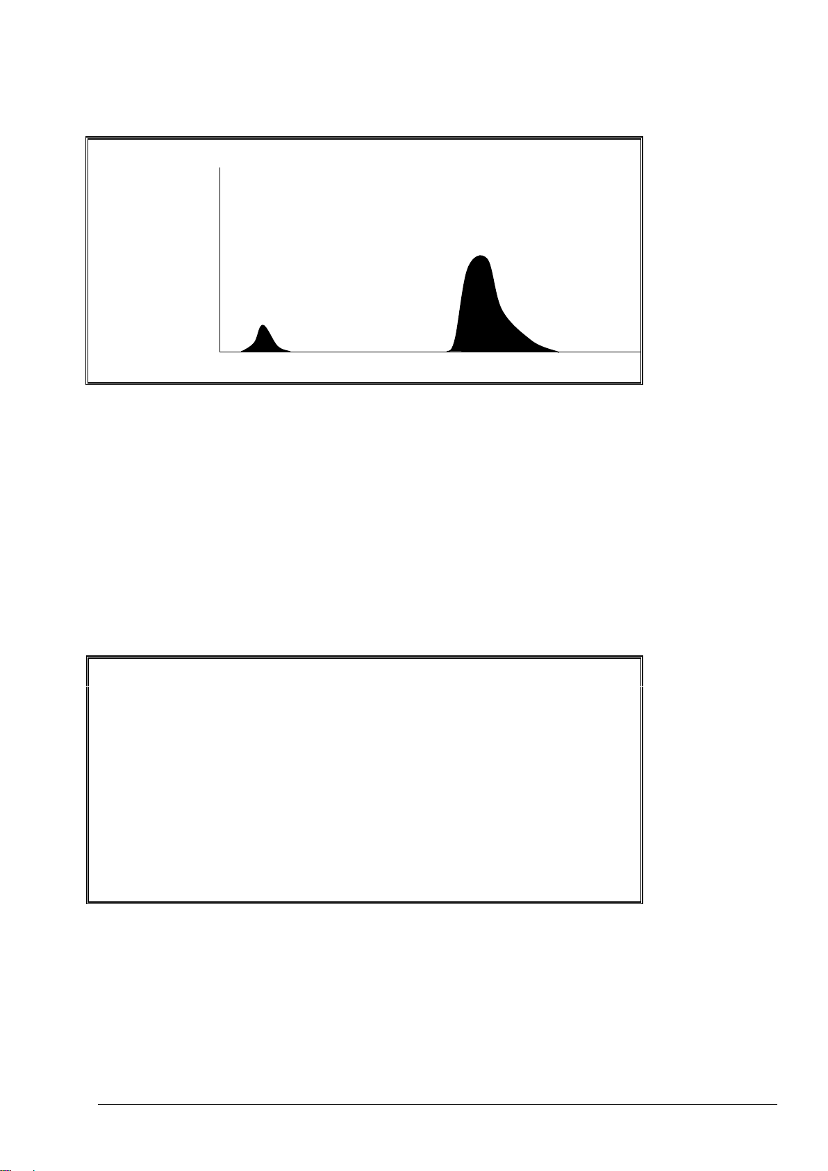
2.1.4 Analysis Graph Screen
The Analysis Graph screen gives information on the current analysis in progress, and allows the user to
monitor the progression of the analysis. This screen gives information on:
- The current atmospheric pressure, measured in kPa (e.g. 101.5 kPa).
- The milligram per liter un-calibrated (mgu) data from the analysis, for example TICmgu or TOCmgu
without any compensation for atmospheric pressure.
- The height of the CO2 peaks in each phase of the reaction (e.g. 956ppm CO2).
- The current MFC flow in l/h (e.g. 10.0 l/h).
- The temperature of the analyzer in °C (e.g. 26°C).
- The CO2 instantaneous value (e.g. 56ppm CO2i) and the CO2 zero value (e.g. 12ppm CO2z) of the
reaction.
- The elapsed time (e.g. 265s) since the start of the analysis.
2.1.5 Reagent Status Screen
If the Reagent Status screen has been activated, the estimated number of days left for each reagent type is
shown on the display.
If the reagents run low, a LOW REAGENTS fault is activated. This fault has to be cleared by resetting the
reagent level in the Install New Reagents menu.
Note that the LOW REAGENTS fault can be set as a warning (where the common fault relay will activate) or a
notification, in which case a special programmable relay is required to signal the LOW REAGENTS condition.
Page 21
Page 22

S E L E C T L E V E L 0 9 : 1 7 : 2 8 1 2 - 0 9 - 0
2
1 < O P E R A T I O N 2 C A L I B R A T I O N 3 M A I N T E N A N C E
0 9 : 1 7 : 2 8 1 2 - 0 9 - 0
2
E N T E R P A S S W O R D F O R O P E R A T I O N S E C U R I T Y D O M A I N [ 1 2 3 4 ]
2.1.6 Select Level Menu
The Select Level screen allows the user to access the operation, calibration and maintenance menus.
1. Operation. This menu gives access to the basic operation of the BioTector and allows access to the
archives. The level can be password protected using the Password menu.
2. Calibration. This menu allows the user to run zero and span calibration cycles. The level can be
password protected using the Password menu.
3. Maintenance. This menu allows the user to test the individual components of the BioTector for
diagnostics, to download data, to program the software functions and to program the system specific
settings in the BioTector. The sub menus in this level can be password protected using the Password
menu.
2.1.7 Enter Password Menu
The BioTector has separate passwords for all levels/security domains, which are operation, calibration
diagnostics, commissioning, system configuration and hardware configuration.
These passwords are programmable, and if a password has been set up for a particular level in Password
menu (see Section 8.3.14 Password for details), then it must be entered before the BioTector will grant
access to the password-protected security domains.
Use of a higher menu level password also allows access to lower levels/domains.
Page 22
Page 23

Maintenance should only be carried out when “SYSTEM STOPPED” message
is displayed on the top left corner of the main Analysis Data screen or when
the system is powered down. When “REMOTE STANDBY” or “SYSTEM
RUNNING” message is displayed on the screen, stop the BioTector using the
“Finish & Stop” or “Emergency Stop” function.
Caution
2.2 Operation Menu
Operation Menu Diagram
Operation menu allows the user to start and stop the analyzer. Menus related to system operation are also
accessed using this menu.
2.2.1 Start Stop
The user can Start or Stop the BioTector using the Start Stop menu.
1. Remote Standby. Remote Standby is an optional function, which is activated from Input 19 (by default) on
the Signal PCB (e.g. from a flow switch). A “REMOTE STANDBY” message is displayed on the top left
corner of the main Analysis Data screen to indicate that the BioTector is in remote standby state. When
remote standby signal is activated, the BioTector stops analyzing. All menu access and operational
functions remain as for BioTector normal running state. The BioTector runs one standby reaction every 24
hours, at the time programmed for the Pressure/Flow Test (at 08:15 AM by default). Sample is not taken
during the remote standby reaction (only acid and base reagents are used). This reaction is tagged as “RS”
(Remote Standby) in the system reaction archive. The 4-20mA signal or other output devices are not
updated. When remote standby signal is deactivated, the BioTector starts analyzing.
When remote standby signal is activated, the “Finish & Stop” or “Emergency Stop” must be selected before
using such functions as Install New Reagents, Zero and Span Calibrations, Process Tests etc. If the
BioTector is stopped using the “Finish & Stop” or “Emergency Stop” functions or automatically by a system
fault, it will not be possible to start the BioTector by the removal of the remote standby signal. The “Start”
function must be used to re-start the BioTector. When BioTector is started while the remote standby signal
is activated, BioTector goes into remote standby state. The manual grab sample analysis can be carried out
normally using the Manual Program menu when the BioTector is in remote standby state.
Page 23
Page 24

Quick Startup Function: During maintenance, system testing etc. it may be
necessary to quickly start and stop the BioTector to check various parameters.
Pressing the ENTER key for the “Start”, when the RIGHT ARROW key is also
pressed, bypasses the Pressure/Flow Test sequence, ensuring a quick startup.
When the quick startup function is used, system will log a “28_NO PRESSURE
TEST” warning in the fault archive and will start operation. The same warning will
also be logged, when the BioTector is started from the Reagents Setup, Manual
Program and Calibration menus using this function.
2. Start. This function starts the BioTector. When BioTector is started, the multi-stream operation sequence (if
programmed) is reset. BioTector performs Ozone Purge, Pressure/Flow Test, Reactor Purge and Analyzer
Purge sequences automatically before starting its analysis.
Ozone Purge sequence purges any residual ozone through the ozone destructor.
Pressure/Flow Test sequence confirm that there is no gas leak and there is no gas flow
restriction in the BioTector.
Reactor Purge sequence purges any liquid from the reactor through the Sample Out Valve.
Analyzer Purge sequence purges any CO2 gas from the CO2 Analyzer through the Exhaust
Valve.
An “*” is displayed to let the operator know the function has been activated. If there is a fault in the system,
it will not be possible to start the analyzer until the fault has been rectified.
3. Finish & Stop. When this function is activated from the keyboard, the BioTector stops as soon as its
present reaction is completed. An “*” is displayed to let the operator know the function has been activated.
4. Emergency Stop. When this function is activated the BioTector cancels the execution of the present
reaction and quickly stops operation after the Ozone Purge, Reactor Purge and CO2 Analyzer Purge
sequences. An “*” is displayed to let the operator know the function has been activated. The Emergency
Stop has highest priority, and always overrules the “Finish & Stop” function.
Page 24
Page 25

I N S T A L L N E W R E A G E N T S 0 9 : 1 7 : 2 8 1 2 - 0 9 - 0
2
C O N F I R M T H E F O L L O W I N G : 1 < N E W A C I D C O N N E C T E D 8 0 m g / l M n S O 4 . H 2 O 2 R E S E T A C I D M O N I T O R 2 5 . 0 l ~ 6 1 D A Y S 3 N E W B A S E C O N N E C T E D
4 R E S E T B A S E M O N I T O R 2 5 . 0 l ~ 6 1 D A Y S 5 T O C 2 0 0 m g C , T I C 5 0 m g C C O N N E C T E D 6 S T A R T N E W R E A G E N T C Y C L E
N O T E : B I O T E C T O R W I L L S T O P W H E N T H E N E W R E A G E N T S C Y C L E I S C O M P L E T E
2.2.2 Reagents Setup
This menu allows the user to access the Reagent menus.
1. Install New Reagents. Menu used to install and prime the reagents in the BioTector. Any “85_Reagents
Low” and “20_No Reagents” warnings and notifications can also be reset in this menu.
2. Purge Reagents & Zero. Menu used to purge the reagents, and carryout a zero calibration cycle.
2.2.2.1 Install New Reagents
The install new reagents procedure is an automatic procedure for installing new reagents, setting the zero
offset by Zero Calibration cycle, setting the reaction check levels and checking the span by Span Calibration
or Span Check cycles. Span Calibration or Span Check cycles are part of the Install New reagents sequence
if SPAN CALIBRATION or SPAN CHECK is activated in New Reagents Program menu. The basic Zero
Check/Calibration and Span Check/Calibration parameters (operation ranges, number of reactions, standard
solution concentrations etc.) are programmed in Zero Calibration and Span Calibration menus respectively
(see Section 2.3 Calibration Menu for details). The comprehensive Zero Check/Calibration and Span
Check/Calibration parameters are programmed in Zero Program and Span Program menus respectively (see
Section 8.3.4.3 Zero Program and 8.3.4.4 Span Program for details).
To run the Install New Reagents cycle, the BioTector must be stopped. Confirm that all or the corresponding
new reagents have been installed on the BioTector, for instance for acid reagent, select New Acid Connected,
and press the ENTER key. A tick mark will appear as confirmation that the new acid has been connected.
Note that when one or more reagent volumes are updated in Reagents Monitor menu, system automatically
resets the new reagents volumes in this menu and also updates the figures displayed in the main Reagents
Status screen.
All reagents volumes can be reset while system is running. This function allows the user to top up the
reagents, without stopping the system. However, when acid and/or base reagents are replaced or topped up,
system requires a new Zero Calibration cycle. A “ZERO CALIBRATION REQUIRED” warning will be
displayed on the screen when RESET ACID MONITOR and/or RESET BASE MONITOR are selected.
Therefore, it is strongly recommended to stop the BioTector and activate the Start New Reagent Cycle or to
run the Zero Calibration cycle using the Zero Calibration menu. Failure to do so may have an impact on
system zero response and the analysis results.
Page 25
Page 26

When all or the necessary reagents have been confirmed to be connected and reset in this menu, and when
Start New Reagent Cycle is selected, the Install New Reagents cycle will be executed. It is the responsibility
of the user to make sure that all reagent volumes are programmed correctly in Reagents Monitor menu, the
reset of the reagents monitoring are carried out correctly in Install New Reagents menu and finally if
necessary the Zero Calibration cycle is activated either with the Start New Reagent Cycle function in Install
New Reagents menu or with the Run Zero Calibration function in Zero Calibration menu.
The Install New Reagents cycle consists of the following steps:
1. Reagent Purge: System purges and fills all reagent lines with the new reagents.
2. Zero Calibration: The Zero Adjust (zero offset) level is set for all analysis ranges, and the Reaction
Check level for TOC is updated (if the CO2 LEVEL is programmed as AUTO in Reaction Check
menu).
3. If Span Calibration or Span Check is activated in New Reagents Program menu, a Span Calibration
or Span Check is carried out.
Once the procedure is completed the BioTector either stops or returns online, depending on the programmed
setting of AUTOMATIC RE-START in New Reagents Program menu (see Section 8.2.5 New Reagents
Program for details).
2.2.2.2 Purge Reagents & Zero
The Purge Reagents & Zero function is an automatic procedure to purge the reagents, to set the zero offset
and to set the reaction check levels in the BioTector. The program settings for the Reagent Purge are set up
in the Reagents Purge menu.
1. Purge Reagents & Zero. This option allows the user to run the Purge Reagents & Zero cycle.
2.2.3 System Range Data Screen
This menu displays the system specific, factory calibrated, analysis range data for all measured components
(e.g. TIC, TOC, TC). BioTector can be calibrated with up to 3 analysis ranges for each measured component.
When a specific component of a sample (e.g. TOC) is measured at a specific range (e.g. Range 2), the
analysis of any other components (e.g. TIC etc.) of the sample are also carried out at the same analysis
range.
Page 26
Page 27

M A N U A L P R O G R A M 0 9 : 1 7 : 2 8 1 2 - 0 9 - 0
2
1 < R U N A F T E R N E X T R E A C T I O N 2 R U N A F T E R 0 0 : 0 0 3 R E T U R N T O O N - L I N E S A M P L I N G Y E S
4 R E S E T M A N U A L P R O G R A M 5 6 M A N U A L 1 , 4 R A N G E 1 7 M A N U A L 2 , 4 R A N G E 3 8 M A N U A L 3 , 4 R A N G E 2 9 M A N U A L - , - - - R A N G E - 1 0 M A N U A L - , - - - R A N G E - 1 1 M A N U A L - , - - - R A N G E -
1 2 M A N U A L - , - - - R A N G E - 1 3 M A N U A L - , - - - R A N G E - ▼
2.2.4 Manual Program Menu
Manual Program menu allows the user to run system in manual operation mode in order to analyze grab
samples/standards or a sequence of samples/standards manually. This is achieved by one or a set of Manual
Valves installed in the system. The manual analysis sequence can be started at the end of the current
reaction, or at a time set by the user. When the manual sequence is complete, the system can be
programmed to return online automatically. Note that all cleaning cycle, pressure/flow tests, zero or span
cycles are interrupted by the manual operation mode. The Sample Pump reverse operation is also disabled
during the manual operation mode by default, unless a Manual Bypass Valve is installed in the system and
the REVERSE time is programmed for the corresponding Manual Valve in Sample Pump menu. All items in
this menu can be modified when the BioTector is running unless:
- No Manual Valves have been defined in the Output Devices menu.
- The manual mode is currently running.
- The manual mode is scheduled to start when the current reaction is completed.
Note that the Manual mode always starts at the first programmed valve, and works its way down the
programmed sequence.
1. Run After Next Reaction. To start the manual operation mode sequence after the next reaction the
BioTector is currently running, press the ENTER key at this menu item. An “*” will indicate that this
function has been selected. If the BioTector is stopped, then the Manual mode will start immediately. To
deactivate this function before the manual operation mode has started, press the ENTER key again, or
activate an alternative function. In systems built with the remote control of Manual Program option, the
remote signal (Manual Mode Trigger from Input 7) activates the Run After Next Reaction function.
2. Run After 00:00. Similar to menu option 1 above, but the manual operation mode starts after the
programmed time.
3. Return to On-line Sampling. This menu item allows the user to specify whether the BioTector should
stop (with NO setting) or return to online monitoring (with YES setting) when the manual operation
sequence is complete.
4. Reset Manual Program. Use this function to reset all the programmed settings to their default values.
6. - 30. Manual. In order to analyze one or a number of samples/standards using the manual operation mode,
first connect the sample/standard to the manual port/s outside the BioTector. Then, select the
corresponding Manual Valve in this menu (the first setting). Then, enter the number of samples (number
of analysis reactions) to be taken through each Manual Valve (the second setting). Finally select the
correct analysis range (RANGE 1, 2 or 3) if the concentration levels of the sample/standard are known.
See System Range Data screen (see Section 2.2.3 System Range Data Screen for details) to view the
available system ranges and to select the correct operation range. If the concentration levels of the
samples/standards are not known, select AUTO so that BioTector can automatically select the optimum
analysis range. When RANGE is programmed as AUTO, a minimum of five analysis reactions is
recommended (the second setting) so that BioTector can find the optimum operation range with its
automatic exceedance tracking function. When AUTO option is selected, depending on analysis range
and system response, the first two or three analysis results may need to be discarded.
Page 27
Page 28

2.2.5 Reaction Archive Screen
The Reaction Archive holds information on TIC, TOC, TC, VOC (in mgC/l), COD, BOD (in mgO/l), LPI (%), LP
(l/h), Flow (m3/h), stream valve, reaction range, start date & time and related analysis information for the last
9999 reactions depending on system analysis type and specific configuration settings. If the archive is full,
then every new reaction overwrites the oldest one in the archive. As the Reaction Archive contains 9999
events, the user must first enter the date at which the viewing of the archive starts. The Enter Date menu
allows the user to specify the date of the first displayed reaction from the archive.
Each reaction record in the reaction archive contains:
- Start Time - reaction start time, which is displayed without seconds in this menu
- Date - reaction date
- Reaction Type - with the prefixes below:
S1 to S6: Reactions from stream 1 to stream 6.
M1 to M6: Reactions from manual sample stream 1 to manual stream 6.
√ Sample sensor detected the sample or there is no significant quantity of air
bubbles in the stream/manual grab sample lines.
x Sample sensor detected no sample or there is significant quantity of air
bubbles in the stream/manual grab sample lines. See Sample Status in
section 8.3.8 Fault Setup for details.
CF: Full cleaning reaction.
W: Reactor wash reaction.
RS: Remote standby reaction.
ZC: Zero calibration reaction.
ZK: Zero check reaction.
ZM: Manually input zero adjust.
SC: Span calibration reaction.
SK: Span check reaction.
SM: Manually input span adjust.
A1 to A6: 24 hours average result from stream 1 to stream 6.
The user can navigate through the displayed reactions individually by pressing the UP and DOWN keys each
time, or can navigate in steps of 10 reactions using the LEFT and RIGHT keys. Depending on system
analysis type (e.g. VOC, TC –TIC etc.) and system display options (e.g. COD, BOD and/or LPI) settings,
BioTector displays additional reaction data held on additional Reaction Archive screens. To access the
screens, press the ENTER key, and to return to the previous screen, press the ESCAPE key.
Page 28
Page 29

When the time is changed, it is possible for the BioTector to automatically start up if the
new time is after the startup time for a scheduled task, for example the startup time for
a manual sample sequence in Manual Program menu.
2.2.6 Fault Archive Menu
In the Fault Archive menu, the user can view the last 99 faults/warning/notification events logged in the
system, confirm if these events are current or not, and acknowledge the current events. If the archive is full,
then every new event overwrites the oldest one in the archive. The user can navigate through the displayed
reactions individually by pressing the UP and DOWN keys each time, or can navigate in steps of 10 reactions
using the LEFT and RIGHT keys. See Section 9 Troubleshooting of System Fault, Warning and
Notification Events for a list of all systems fault, warning and notification events.
The faults archive events are divided into three categories:
- Fault: Faults are categorized as events, which stop BioTector operation. The 4-20mA signals are set
to the fault level, and the fault relay is activated. The BioTector cannot be started unless the fault in
the archive has been acknowledged.
- Warning: Warning is a minor event, which does not require the BioTector to stop. The 4-20mA
signals are not changed, only the fault relay is activated.
- Notification: A notification is an information (e.g. “86_Power Up”, “87_Service Time Reset” etc.)
displayed on the screen.
To acknowledge any current events marked with an “*” in the archive, first identify and locate the
faults/warnings/notification. Follow the necessary troubleshooting procedures to solve the problem. See
Section 9 Troubleshooting of System Fault, Warning and Notification Events for details.
Acknowledge the fault by pressing the ENTER key in the Fault Archive menu. Please note that there are
system faults (e.g. 05_Pressure Test Fail), which cannot be acknowledged by the user. Such faults are reset
and acknowledged automatically by the system when system is started, when system is rebooted or when the
fault condition is solved. If an event cannot be acknowledged when the system is running, a “SYSTEM
RUNNING” message is displayed on screen.
2.2.7 Time & Date Menu
This menu allows the system time and date to be set by the user. To change the system time or date (hours,
minutes, seconds, day, month and year), press the ENTER key, enter the new time and date and press the
ENTER key again.
In order to change the system date format, press the ENTER key, select new date format from the following
day, month and year options: DD-MM-YY, MM-DD-YY, YY-MM-DD and press the ENTER key again.
2.2.8 Contact Information
Contact Information menu displays the manufacturer/distributor contact details.
Page 29
Page 30

Z E R O C A L I B R A T I O N 0 9 : 1 7 : 2 8 1 2 - 0 9 - 0
2
1 < Z E R O A D J U S T 1 0 . 0 [ 0 . 0 ] 2 2 0 . 0 [ 0 . 0 ] 3 3 0 . 0 [ 0 . 0 ] 4 R U N R E A G E N T S P U R G E 5 R U N Z E R O C A L I B R A T I O N 6 R U N Z E R O C H E C K
7 R 1 R 2 R 3 8 Z E R O P R O G R A M 6 , 4 , 4 9 Z E R O A V E R A G E 4 , 2 , 2 1 0
1 1 - - > Z E R O P R O G R A M
ENTER PASSWORD CALIBRATION ZERO CALIBRATION
SPAN CALIBRATION
2.3 Calibration Menu
Calibration menu allows the user to calibrate the analyzer. Zero and Span Calibration menus allow the user to
run the zero and span calibration cycles for a single range or for all system ranges available.
Calibration Menu Diagram
2.3.1 Zero Calibration
Zero Calibration menu allows the user to enter the suggested Zero Adjust values, to start the Reagent Purge
cycle, to start the Zero Calibration and Zero Check cycles and to program the number of zero reactions run at
each range.
1.-3. Zero Adjust. The Zero Adjust is used to compensate any organic contamination in the acid and base
reagents and any absorbed CO2 in the base reagent. The Zero Adjust values are generated automatically
by the system for each range when the zero calibration cycle is completed without any system warnings.
Zero Calibration cycle is activated by selecting the RUN ZERO CALIBRATION function in this menu.
When a Zero Check cycle is run using the RUN ZERO CHECK function, the system only checks the zero
response at each range and displays the suggested Zero Adjust values in brackets “[ ]” for all ranges next
to the current Zero Adjust settings. When a Zero Check cycle is completed, if necessary the suggested
Zero Adjust values can be programmed manually by entering the corresponding suggested Zero Offset
values for each range (1, 2 and 3) in this menu. When the Zero Adjust settings are entered manually,
system logs this information in the reaction archive with the prefix “ZM” (Zero Manual).
4. Run Reagents Purge. The RUN REAGENTS PURGE function is used to prime all reagents in the
BioTector. If necessary, the pump operation time for Reagent Purge cycle can be increased in the
Reagents Purge menu (see Section 8.3.4.5 Reagents Purge for details).
5. Run Zero Calibration. Each time BioTector reagents are replaced or topped up and each time a service
is carried out, it is strongly recommended to use the RUN ZERO CALIBRATION function so that the
system can set the zero offset values automatically. The zero calibration reactions operate in the same
manner as a normal reaction, but BioTector does not take any sample. To start the zero calibration, press
the ENTER key at this menu item. An “*” will indicate that the function is running. At the end of the Zero
Calibration cycle, the following settings are checked and updated:
Page 30
Page 31

1. The Zero Adjust settings for each range are updated automatically by the system using the uncalibrated TOC measurement (not the results seen on the LCD screen). If a Zero Check is used
to check the zero offset, the suggested values are shown in brackets “[ ]” next to the actual Zero
Adjust settings.
2. If the CO2 LEVEL is set as AUTO for automatic updating in the Reaction Check menu, then the
reaction check CO2 Level is also updated automatically.
3. The CO2 Level is also checked against the BASE CO2 ALARM setting in Fault Setup menu. If the
measured CO2 Level is greater that the BASE CO2 ALARM value, system generates a “52_HIGH
CO2 IN BASE” warning.
6. Run Zero Check. Zero Check cycle is similar to the Zero Calibration above, but BioTector does not
update any of the Zero Adjust or CO2 Level settings. System only checks the BASE CO2 ALARM
described above.
8. Zero Program. Zero Program function allows the user to program the number of zero reactions run at
one or more ranges (R1, R2 and/or R3). When the number of zero calibration reactions for one or two of
the ranges is set to zero, system runs the zero cycle on the programmed range or ranges and calculates
the Zero Adjust values for the other ranges automatically. It is recommended not to modify the factory set
Zero Program values unless it is absolutely necessary. Any unnecessary modification in this setting may
have an impact on the zero offset values.
9. Zero Average. Zero Average function allows the user to program the number of zero reactions to be
averaged for each range (R1, R2 and/or R3) at the end of the zero cycles. It is recommended not to
modify the factory set Zero Average values unless it is absolutely necessary. Any unnecessary
modification in this setting may have an impact on the zero offset values.
11. Zero Program. Zero Program is a link to Maintenance, System Configuration, Sequence Program,
Zero Program menu. See Section 8.3.4.3 Zero Program.
Page 31
Page 32

S P A N C A L I B R A T I O N 0 9 : 1 7 : 2 8 1 2 - 0 9 - 0
2
1 < T O C S P A N A D J U S T 1 1 . 0 0
2 2 1 . 0 0 3 3 1 . 0 0 4 T I C S P A N A D J U S T 1 1 . 0 0 5 2 1 . 0 0
6 3 1 . 0 0 1 0 R U N S P A N C A L I B R A T I O N 1 1 R U N S P A N C H E C K 1 2 1 3 S P A N P R O G R A M 6 1 4 S P A N A V E R A G E 4 1 5 R A N G E 1 1 6 T O C C A L S T D 1 0 0 . 0 m g C / l
1 7 T O C C H E C K S T D 5 0 . 0 m g C / l 1 8 T I C C A L S T D 1 2 5 . 0 m g C / l 1 9 T I C C H E C K S T D 6 0 . 0 m g C / l 2 2
2 3 - - > S P A N P R O G R A M
S P A N A D J U S T 0 9 : 1 7 : 2 8 1 2 - 0 9 - 0
2
S T A N D A R D R E S U L T 1 < T O C S P A N A D J U S T 1 0 0 . 0 2 2 1 . 0 0 3 3 1 . 0 0
4 T I C S P A N A D J U S T 1 1 . 0 0
S P A N A D J U S T 0 9 : 1 7 : 2 8 1 2 - 0 9 - 0
2
S T A N D A R D R E S U L T 1 < T O C S P A N A D J U S T 1 0 0 . 0 9 9 . 5 2 2 1 . 0 0 3 3 1 . 0 0
4 T I C S P A N A D J U S T 1 1 . 0 0
2.3.2 Span Calibration
Span Calibration menu allows the user to enter the Span Adjust values manually, to start the Span Calibration
and Span Check cycles and to program the number of span reactions, span operation range and the
concentrations of the standard solutions used. Above menu displays the parameters for the TIC & TOC
systems. In TC and VOC Systems, the relevant parameters, identified below, are displayed in this menu.
1.-3. TOC Span Adjust. This menu item allows the user to set the TOC span adjust factors manually by
entering the STANDARD solution used and the calibrated average reaction RESULT at each range (1, 2
and 3). When the STANDARD and RESULT values are entered, system automatically calculates the
corresponding span factors of each parameter for each range. In TC and VOC systems, this function is
named as TC Span Adjust. In order to manually set the Span Adjust factors:
First enter the concentration of the standard solution used.
Next enter the average result.
When the ENTER key is pressed again, the new span factor is automatically calculated. In order to set the
span adjust factors to 1.00, enter 0.0 values for both standard and result.
Page 32
Page 33

4.-6. TIC Span Adjust. This menu item allows the user to set the TIC span adjust factors manually for each
range as described for TOC Span Adjust above.
10. Run Span Calibration. This function starts the Span Calibration cycle. The span calibration reactions are
run at a single range programmed by the RANGE in this menu below. At the end of the span calibration
cycle, BioTector automatically calculates the Span Adjust factors and displays it for Span Adjusts above.
Unless it is manually modified, the same Span Adjust factor calculated for the programmed RANGE in
this menu is used for the other two ranges as well. The span reactions operates in the same manner as a
normal reaction, but the Sample Pump reverse operation is disabled to prevent the contamination of the
standard solution connected to calibration/manual port. Span Calibration reactions have the prefix of
“SC”.
11. Run Span Check. This function starts the Span Check cycle. The operation is similar to the Span
Calibration cycle above, but BioTector does not update any Span Adjust values at the end of the span
check cycle. Span Check reactions have the prefix “SK”.
13. Span Program. Span Program function allows the user to program the number of span reactions to be
carried out during the Span Calibration and Span Check cycles. It is recommended not to modify the
factory set Span Program value unless it is absolutely necessary. Any unnecessary modification in this
setting may have an impact on the span adjust values.
14. Span Average. Span Average function allows the user to program the number of reactions to be
averaged at the end of the Span Calibration and Span Check cycles. It is recommended not to modify the
factory set Span Program value unless it is absolutely necessary. Any unnecessary modification in this
setting may have an impact on the span adjust values.
15. Range. Range function allows the user to program the operation range at which the Span Calibration and
Span Check reactions are carried out. If the selected range is in conflict with the programmed
CALIBRATION STANDARD concentration in this menu, system automatically displays a “Caution!
Reaction range or Standard is Incorrect” warning. See System Range Data screen (see Section 2.2.3
System Range Data Screen for details) in order to select the correct operation range or correct
standard solution.
16. TOC Cal Std. TOC Calibration Standard function allows the user to program the concentration (mgC/l) of
the TOC standard solution used in Span Calibration reactions. If the programmed concentration level is in
conflict with the programmed RANGE above, system automatically displays a “Caution! Reaction Range
or Standard is Incorrect” warning. See System Range Data screen in order to select the correct operation
range or correct standard solution. If TOC Calibration Standard is programmed as 0.0mgC/l, system does
not calculate or update any Span Adjust factors and therefore omits any span related warnings defined
above. See Section 6.2 Calibration Standards for the details of BioTector standard solutions and
preparation procedures. In TC systems, this parameter is named as TC Calibration Standard.
17. TOC Check Std. TOC Check Standard function allows the user to program the concentration (mgC/l) of
the TOC standard solution used in Span Check reactions. If TOC Check Standard is programmed as
0.0mgC/l, any span related warnings are omitted. In TC systems, this parameter is named as TC Check
Standard.
18. TIC Cal Std. TIC Calibration Standard function allows the user to program the concentration (mgC/l) of
the TIC standard solution used in Span Calibration reactions. If TIC Calibration Standard is programmed
as 0.0mgC/l, any span related warnings are omitted. In VOC and TC – TIC systems, it is recommended to
run the TIC and TOC calibrations separately using separate standard solutions.
19. TIC Check Std. TIC Check Standard function allows the user to program the concentration (mgC/l) of the
TIC standard solution used in Span Check reactions. If TIC Check Standard is programmed as 0.0mgC/l,
any span related warnings are omitted.
Page 33
Page 34

20. TC Cal Std. In VOC systems, the sum of the TIC and TOC Calibration Standard solution is displayed as
TC Calibration Standard. When TOC Calibration Standard is programmed as 0.0mgC/l, and when a
concentration of TIC Calibration Standard is programmed above, BioTector displays the TC Calibration
Standard as 0.0mgC/l on purpose. This allows the calibration of TIC without any effect on the TC
calibration. See definitions for TOC Calibration Standard above, Section 8.3.4.4 Span Program and
Section 6.2 Calibration Standards for further details.
21. TC Check Std. In VOC systems, the sum of the TIC and TOC Check Standard solution is displayed as
TC Check Standard. When TOC Check Standard is programmed as 0.0mgC/l, and when a concentration
of TIC Check Standard is programmed above, BioTector displays the TC Check Standard as 0.0mgC/l on
purpose. This allows the check of TIC without any effect on the TC check.
23. Span Program. Span Program is a link to Maintenance, System Configuration, Sequence Program,
Span Program menu (see Section 8.3.4.4 Span Program).
Page 34
Page 35

Section 3 Technical Specifications
TYPICAL TECHNICAL DATA
Enclosure: Fiberglass Reinforced Polyester
Dimensions (HxWxD): 1250mm x 750mm x 320mm
Enclosure height may increase to 1750mm, depending on system optional
features.
Weight: 90 kg – 120 kg
Enclosure weight may change depending on system optional features.
Power Consumption: 300 W (VA)
Mains Connection: 115V AC, 60Hz or 230V AC, 50Hz (10%)
Other power options are available on request.
Mains Wire Specification: Number of Cores = 3, Current Rating minimum = 10 Amps, CSA (Cross
Sectional Area minimum) = 1.50mm2
Signal Wire Specification: Number of Cores = 8 (+2 cores per additional signal), Current Rating
minimum = 1 Amp, CSA (Cross Sectional Area minimum) = 0.22mm2.
FEATURES IN DETAIL
Display: High Contrast 40 Character x 16 Line Backlit LCD with CFL Backlight
Data Storage: Previous 9999 analysis data on screen in the microcontroller memory and
storage of data archive for the lifetime of the analyzer in the SD/MMC card
Previous 99 fault data on screen in the microcontroller memory and storage
of fault data archive for the lifetime of the analyzer in the SD/MMC card
SD/MMC Card: Flash memory card for data transfer and for software & configuration updates
Operation: Microcontroller with BioTector OS3 Software and Membrane Keyboard
Language Options: English, French, German
Other language options are available on request.
INPUT & OUTPUT SIGNALS
Standard Output: One programmable 4-20mA output signal (typically for TOC)
For systems requiring more than six 4-20mA standard outputs, 4-20mA
Output Multiplex option is implemented to provide 4-20mA data for up to 35
output signals.
Digital Output: Three freely programmable system relays (volt free changeover contact with
a current rating of 1Amp at 30V DC)
One of the system relay is factory set to Fault.
Data Transfer Port: SD/MMC Card and serial RS232 Output for Printer, PC or Data Logger
OPTIONAL FEATURES
Result Output: TIC, TC, VOC, after correlation COD, BOD
Remote Control: Input for remote start / standby
Input for remote stream and range selection
Input for remote manual grab sample analysis
Network Control Unit for remote access over Internet or Intranet connection
using HTTP over TCP/IP protocol
Industrial Interface: Modbus, Profibus, Ethernet
(when any of the Modbus, Profibus or Ethernet option is selected, the digital
output signals are sent through the relevant device with its specific
communication protocol)
Calibration & Cleaning: Valves for Automatic Calibration and Sample Line Cleaning
Multi-stream: Valves for up to 6 streams with up to six 4-20mA signals (TIC & TOC, TC,
VOC systems). The number of available outputs depends on the manual
stream configuration.
Manual stream: Valves for up to 6 manual streams with up to six 4-20mA signals (TIC & TOC,
TC, VOC systems). The number of available outputs depends on the multistream configuration.
Page 35
Page 36

4-20mA Outputs: As individual signal up to maximum of 6 or as multiplex signal up to maximum
of 35. Maximum impedance: 500 ohms.
Hazardous Area: Certification options are available to European Standards (ATEX for Zone 1
and Zone 2) and to North American Standards (Class I Division 1 and Class I
Division 2). Other options, such as IECEx, are available on request.
CONSUMABLES Typical Replacement Frequency & Consumption
Acid & Base: 5 - 15 weeks/25 Liters (application dependent)
Instrument Air: 1.5 bar, - 20°C dew point (free of water, oil and dust)
Average consumption is less than 5.4 m3/hour.
Filter pack is recommended and available to meet the air quality specification.
BioTector Air Compressor is available for air supply.
Service: 6 Monthly Intervals
ANALYSIS PARAMETERS
Oxidation Method: Patented Two-Stage Advanced Oxidation Process using Hydroxyl Radicals
TOC Measurement: NDIR measurement of CO2 after oxidation
Measurement Terms: TOC (Total Organic Carbon) including Non-Purgeable Organic Carbon
(NPOC) and Purgeable Organic Carbon (POC)
BioTector TIC&TOC mode measures NPOC.
BioTector VOC mode measures TOC as NPOC+POC.
Measured Components: TOC (NPOC)
TOC (NPOC + POC)
TIC
TC
VOC (POC)
TOC as TC - TIC
COD*
BOD*
* COD & BOD by correlation algorithm incorporating TOC measured results
Cycle Time: TOC typically 6.5 minutes
MONITORING RANGES: TOC
Standard Range 0-250mgC/l up to 0-20,000mgC/l
Up to 3 ranges configurable for each component within each range band detailed above.
A wide combination of TOC monitoring ranges, including higher ranges, are available upon request.
Exceedance Tracking: Full Exceedance Tracking to Maximum Range
Range Selection: Automatic or Manual Range Selection
Repeatability: 3% of reading or 0.3mg/l whichever is greater, with Automatic Range
Selection
Detection Limit: 0.6mg/l with Automatic Range Selection
Sodium Chloride Interference:
TOC
All Ranges None
Page 36
Page 37

SAMPLE & ENVIRONMENTAL CONDITIONS
Sample Volume: Up to 8.0ml
Sample Inlet Pressure: Typically ambient (for applications with high sample pressure, sampling
systems are available)
Drain Pressure: Typically ambient (for applications with high drain pressure, optional systems
are available)
Sample Inlet Temperature: 2°C – 60°C (36°F - 140°F)
Sample Flow Rate: Minimum 100ml per sample
Sample Particle Size: Up to 2 mm, soft particulates
Ambient Temperature: 5°C – 40°C (41°F - 104°F)
Air conditioning and heating options are available.
Humidity: 5% - 85%, non-condensing
Ingress Protection: IP44
Optional IP54 with air purge
System Sound: < 60 dBa
The manufacturer has a continuous research and development program. Specifications may
therefore be changed without notice. For specification updates, please contact the
manufacturer.
Page 37
Page 38

1 2 3
16
11
21
22
23
24
12
20
4 5 7
8
10
9
17
26
28
27
14
13
6
15
19
18
25
Section 4 Introduction
4.1 BioTector Major Components
4.1.1 Analysis Enclosure
Figure 1 and table 2 below shows the typical major analysis enclosure components of BioTector TOC
Analyzers.
Figure 1 BioTector analysis enclosure major components
Page 38
Page 39

1
Air Isolation Valve, OV1
2
Pressure Relief Valve
3
Cooler
4
Ozone Generator
5
Ozone Destructor
6
Exhaust Valve, MV1
7
Exhaust Filter
8
Hepa Filter
9
Rotary Valve, OV2
10
Injection Valve, MV7
11
NDIR CO2 Analyzer
12
Oxygen Pressure Regulator
13
Non-return Valve (Check Valve)
14
Ozone Line Filter
15
Sample Valve (ARS Valve), MV4
16
Molecular Sieve Bed
17
Oxygen (O2) Tank
18
Acid Valve, MV6
19
Base Valve, P2
20
Filter Board (Electronic Filter PCB)
21
Sample Pump, P1
22
Acid Pump, P3
23
Base Pump, P4
24
Mixer Reactor
25
Sample Out Valve, MV5
26
Liquid Leak Detector
27
Manual/Calibration Valve (Span Calibration Valve), MV9
28
Vent
Table 2 BioTector analysis enclosure major components
Page 39
Page 40
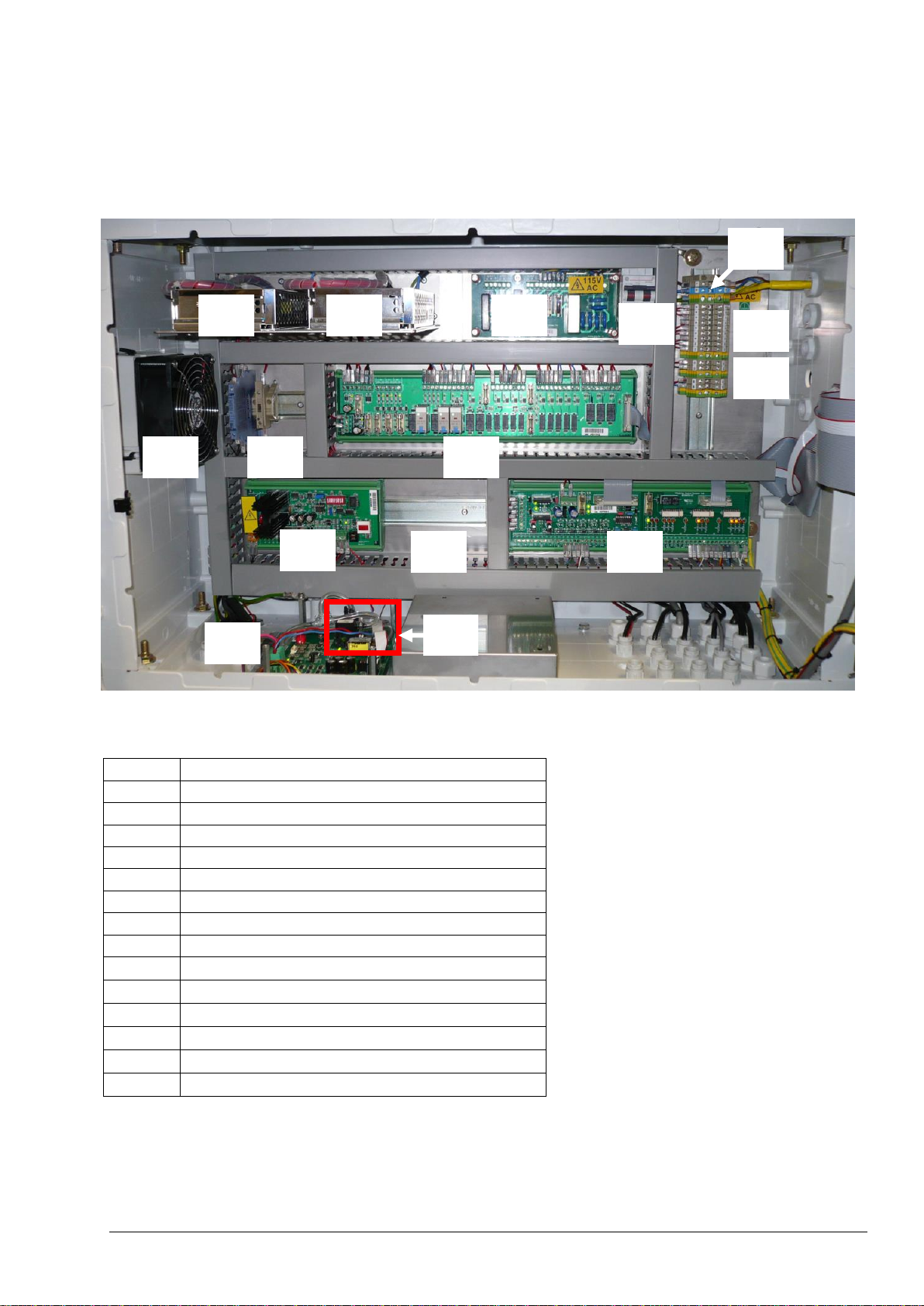
1
Power Supply (for Main Board/Motherboard)
2
Power Supply (for Pumps and Valves)
3
Power PCB (Mains PCB)
4
Main Power Switch
5
Mains Terminals
6
Relay Terminals
7
4-20mA & Stream Alarm Terminals
8
Fan
9
4-20mA Isolators
10
Relay PCB
11
Ozone PCB
12
Auxiliary/Stream Expansion PCB (Option)
13
Signal PCB
14
Oxygen (O2) Controller Board
15
Mass Flow Controller (MFC)
1 2 3 4 5
6
11
13
14
7
8 9 10
12
15
4.1.2 Electronics Enclosure
Figure 2 and table 3 below shows the major electronics enclosure components of BioTector TOC Analyzer.
Figure 2 BioTector electronics enclosure major components
Table 3 BioTector electronics enclosure major components
Page 40
Page 41

1
Motherboard (Main Board)
2
LCD Screen Contrast Adjustment Dial
3
Processor PCB
4
MMC/SD Flash Memory Card Slot
1
3
4
2
Figure 3 and table 4 below shows the BioTector main board (motherboard) components.
Figure 3 BioTector main board components
Table 4 BioTector main board components
Page 41
Page 42

4.2 BioTector Operation
Detailed information on the system operation is available, in presentation format, in the MMC/SD card
shipped with the BioTector. It is recommended to review this file to understand the system operation.
The BioTector is designed to provide continuous online single-component (e.g. TOC) or multi-component
(e.g. TOC & TN & TP) monitoring. The BioTector can operate with unfiltered samples including soft
particulates up to 2 mm in diameter, and will give accurate measurements even when fats, high levels of salts
and/or calcium is present in the sample.
In BioTector multi-component analyzers, the system can be configured as a;
1) TIC & TOC system to measure the Total Inorganic Carbon (TIC) and Total Organic Carbon (TOC)
content of a sample. The TOC result obtained from a TIC & TOC system represents the NonPurgeable Organic Carbon (NPOC). The TIC & TOC system is the standard system for samples
which does not contain any volatile organic material or for samples which contains insignificant
concentration of volatile organic material.
2) TC system to measure the Total Carbon (TC) content of a sample. The TC result obtained from a TC
system represents the sum of TIC, NPOC and Purgeable Organic Carbon (POC) content.
3) VOC system to measure the TIC, TOC, TC and Volatile Organic Carbon (VOC) contents of a sample
by means of two analysis reactions in single reactor configuration. VOC result represents the
Purgeable Organic Carbon (POC). The TOC result in a VOC system is calculated from the TC and
TIC measurements as TC – TIC. Therefore the TOC result includes the VOC (POC) content of the
sample. In other words, the TOC result represents the sum of NPOC and POC content.
TC and VOC configurations are system optional features.
As a brief introduction, the operation of BioTector analyzers can be summarized as follows:
i. A sample liquid is brought to the analyzer by means of a peristaltic pump. The sample is injected into
the BioTector reactor chamber.
ii. A patented Two Stage Advanced Oxidation process (TSAO) oxidizes the organic material in the
sample.
iii. The carbon dioxide formed in the oxidation process is sparged and measured by a Non-dispersive
Infrared (NDIR) analyzer.
iv. The results are displayed as TIC, TOC, TC and VOC depending on system configuration.
v. The oxidized liquid is discharged and collected in a sample catch-pot and again depending on system
configuration, the Total Nitrogen and/or Total Phosphorus analysis is carried out applying direct
photometric and/or colorimetric methods.
4.2.1 BioTector Oxidation Method
A patented Two Stage Advanced Oxidation process (TSAO), which uses hydroxyl radicals as the oxidizing
agent, is used for the oxidation of the sample.
The hydroxyl radical oxidation is a powerful oxidation technology, which keeps the wetted reactor parts clean
in all types of applications. The base reagent is used as a cleaning agent, where the sample lines and the
reactor are washed with an automated cleaning cycle. BioTector self-cleaning technology using hydroxyl
radical oxidation together with the automated cleaning cycle ensures that the cleaning of the reactor and the
replacement of sample tubing are not necessary.
Page 42
Page 43

4.2.2 BioTector Sample Injection
The BioTector analyzes a precise volume of liquid. The Sample Pump injects a pre-programmed number of
pulses (half revolutions of pump) of liquid into the reactor for each measurement and therefore the volume of
liquid included in each pulse is consistent irrespective of sample source pressure.
Sample is initially drawn from the source by a peristaltic Sample Pump.
In standard TIC & TOC systems, Manual/Calibration Valve is activated to isolate any stream pressure or
vacuum coming from the sample lines. Sample Pump rotates forward for 4 pulses by default to remove any
pressure/vacuum within the pump tube. Sample Valve rotates 90 degrees clockwise and Sample Pump
rotates forward and injects the sample directly into the reactor with the relevant number of pulses appropriate
to the range. Sample Valve rotates a further 90° clockwise and the sample volume remaining within the
Sample Valve is washed into the BioTector reaction chamber (reactor) by the first TIC acid injection.
In TC systems, the sample injection is carried out similar to the one described for TIC & TOC systems above
but the sample volume remaining within the Sample Valve is washed into the reactor by a small quantity of
acid reagent.
In VOC systems, BioTector carries out two separate sample injections for the two analysis reactions run
consecutively in a single reactor configuration. The first analysis reaction is a TC reaction and the second one
is a TIC & TOC reaction. The sample injection takes place as described for the TC systems and for the TIC &
TOC systems above. Figure 4 shows the typical analysis layout of TIC & TOC, TC and VOC systems below.
Detailed information on sample injection is available, in presentation format, in the MMC/SD card shipped with
the BioTector. It is recommended to review this file to understand BioTector sample injection.
Page 43
Page 44

Figure 4 BioTector analysis layout (typical TIC & TOC system)
Page 44
Page 45
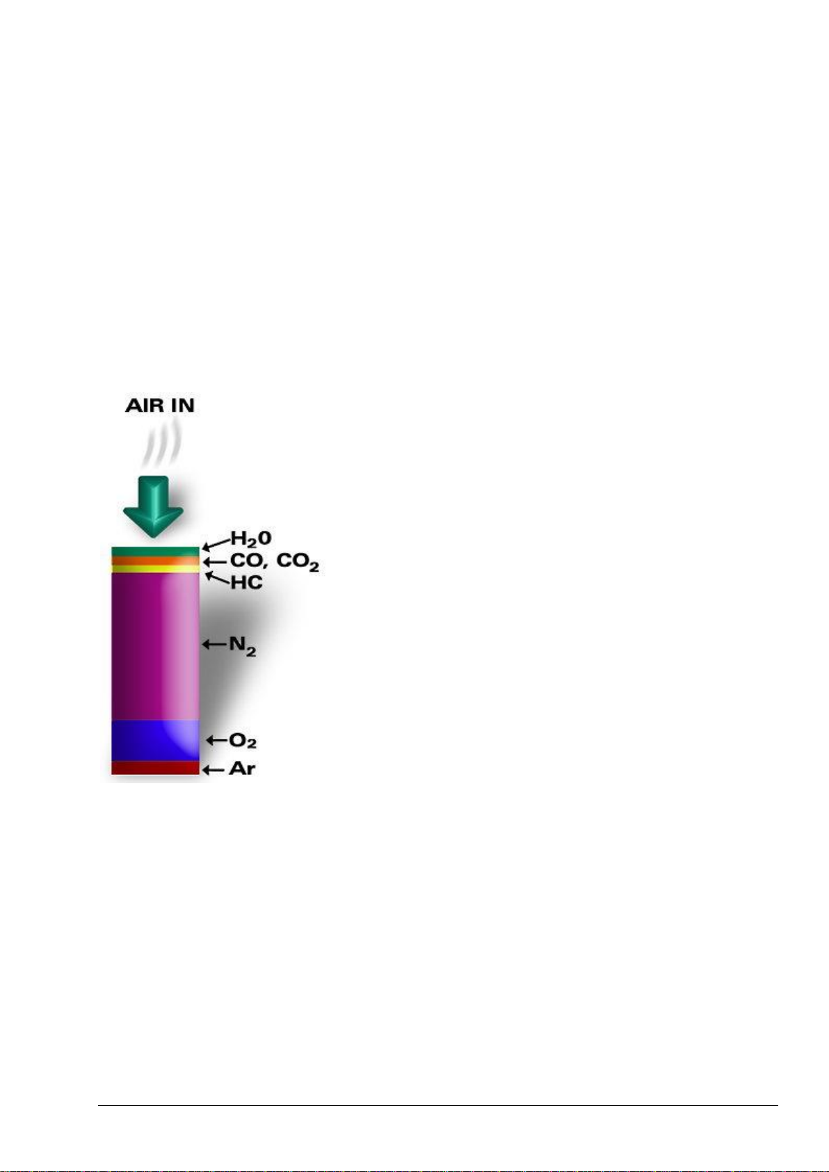
4.2.3 BioTector Oxygen Concentrator
The operation of BioTector oxygen concentrator is based on the crystalline zeolite molecular sieves, which
permits the separation of oxygen gas from the mixture of gases that comprise air. As air flows through a
column or bed of molecular sieve, the component gases it contains are adsorbed and stratified in the order of
their relative affinity to the molecular sieve material. The process may continue until the next to last gas
component stratifies near the end of the bed. Once the full bed length is used, the bed must be regenerated
by desorbing (or purging) the adsorbed gases. Purging is accomplished by reducing the pressure in the bed
and back-flushing with some of the concentrated gas product. Adsorption and desorption are completely
reversible processes and are carried out indefinitely.
The theory behind the operation of the oxygen concentrator is Pressure Swing Adsorption (PSA). This is
based on flowing air through the column (the sieve bed) packed with molecular sieve material. The
components of the air (Water Vapor, Carbon Dioxide, Carbon Monoxide, Hydrocarbons, Nitrogen, Oxygen
and Argon) are adsorbed in order of their relative affinity to the molecular sieve material. Figure 5 shows the
adsorption of air components inside the molecular sieves.
Figure 5 Adsorption of air components in oxygen concentrator molecular sieves.
Once the sieve bed is used, then it is re-generated by purging the adsorbed gasses from the molecular sieve.
This is achieved by removing the air supply from the inlet to the sieve bed, and back-flushing the sieve bed
with some of the concentrated gas product. The typical oxygen purity obtained from a PSA oxygen
concentrator is 93% (±3%) with balance gas Argon.
Figure 6 below shows the layout of BioTector oxygen concentrator and the operation of the Rotary Valve used
for the PSA process.
Page 45
Page 46

Figure 6 BioTector oxygen concentrator layout
Page 46
Page 47

BioTector analysis types are optional features. If the BioTector is built as a TIC & TOC
system only, modifications in the system configuration will be required for TC analysis to
be possible.
4.2.4 BioTector Analysis Types
BioTector TOC analyzer has four factory calibrated analysis types:
1. TIC & TOC (NPOC) Analysis: Total Inorganic Carbon & Total Organic Carbon (Non-Purgeable
Organic Carbon) Analysis
2. TC Analysis: Total Carbon Analysis
3. VOC (POC) Analysis: Volatile (Purgeable) Organic Carbon Analysis
4.2.4.1 TIC & TOC Analysis
1. An unfiltered sample is injected into the BioTector reaction chamber (reactor).
2. An acid reagent (e.g. Sulfuric Acid) is added and the oxygen carrier gas flow is activated to remove
the inorganic carbon. The carbon dioxide gas is sparged by the addition of the acid reagent and is
carried by the oxygen carrier gas and measured with a non-dispersive infrared (NDIR) CO2 analyzer.
The result is displayed as Total Inorganic Carbon (TIC). This reaction phase is called TIC phase.
3. Ozone generator is activated. A base reagent (e.g. Sodium Hydroxide) is injected and the sample is
then oxidized with hydroxyl radicals, a strong oxidizing agent, which is generated by exposing high
pH reagents to ozone. This reaction phase is called Base Oxidation phase. The complete oxidation
of organic compounds takes place and carbonates are formed.
4. After the Base Oxidation phase, the carbonates are sparged in the form of carbon dioxide gas by the
addition of an acid reagent. The carbon dioxide gas is carried by the oxygen carrier gas and
measured with the NDIR CO2 analyzer. The result is displayed as Total Organic Carbon (TOC). This
reaction phase is called TOC phase. The TOC result obtained from the TIC & TOC analysis type
represents the Non-Purgeable Organic Carbon (NPOC).
5. At the end of the reaction, the oxidized sample liquid is discharged from the reactor with increased
oxygen flow.
4.2.4.2 TC Analysis
1. The oxygen carrier gas flow and the ozone generator are activated. Base reagent is injected into the
reactor and hydroxyl radicals are generated by exposing the base reagent to ozone. This reaction
phase is called Pre-Oxidation.
2. An unfiltered sample is injected into the reactor of the BioTector with a low flow of oxygen carrier gas.
3. The volatile organic content of the sample is oxidized with hydroxyl radicals. This reaction phase is
called VOC Oxidation, as the oxidation of the volatile organic matter is achieved without being
sparged.
4. When the VOC Oxidation phase is complete, the oxygen gas flow and the ozone generator is
activated and the remaining Non-Purgeable Organic Carbon (NPOC) content in the sample is
oxidized by the hydroxyl radicals in Base Oxidation phase. The complete oxidation of organic and
inorganic compounds takes place and carbonates are formed.
5. When the oxidation processes are completed, the carbonates are sparged in the form of carbon
dioxide gas by the addition of an acid reagent. The carbon dioxide gas is carried by the oxygen
carrier gas and measured with the NDIR CO2 analyzer. The result is displayed as Total Carbon (TC).
The TC result obtained from the TC analysis type represents the sum of TIC, NPOC and Purgeable
Organic Carbon (POC):
TC = TIC + NPOC + POC
6. At the end of the reaction, the oxidized sample liquid is discharged from the reactor with increased
oxygen flow.
Page 47
Page 48

BioTector analysis types are optional features. If the BioTector is built as a TIC &
TOC system only, modifications in the system configuration will be required for VOC
analysis to be possible.
BioTectors built with the VOC analysis option can be programmed on site to operate
with the TIC & TOC only or TC only analysis types.
4.2.4.3 VOC (POC) Analysis
BioTector Volatile Organic Carbon (VOC) analysis type is a combination of TC analysis followed by a TIC &
TOC (NPOC) analysis. The VOC result obtained from the VOC analysis type represents the Purgeable
Organic Carbon (POC) content of the sample. When both TC and TIC & TOC analysis are complete, the
flowing data is available:
TC result, as measured and displayed from the TC analysis.
TIC result, as measured and displayed from the TIC & TOC analysis. TOC result obtained from the
TIC & TOC analysis represents the NPOC.
TOC result including the VOC, which is calculated from the difference between the TC and TIC:
TOCv = TC – TIC
The TOC result displayed in VOC analysis type includes the purgeable organic carbon (POC) present
in the sample. In other words the TOC result, obtained in VOC analysis type, is the sum of NPOC and
POC:
TOCv = NPOC + POC
VOC (POC) result, which is calculated from the difference between the measured TC (from the TC
analysis), and the sum of measured TIC and measured NPOC (from the TIC & TOC analysis):
VOC (POC) = TC – (TIC + NPOC)
The NPOC result, as measured from the TIC & TOC analysis, is not displayed, it is only used to
calculate the VOC (POC) element in the sample. All displayed results can be programmed in the
system and sent as 4-20mA output signals to an external device.
Page 48
Page 49

Section 5 Installation
5.1 Basic System Requirements
Power and Signal Requirements
Mains Connection: 115V AC, 60Hz or 230V AC, 50Hz (10%)
Mains Wire Specification: Number of Cores = 3
Current Rating minimum = 10 Amps
CSA (Cross Sectional Area minimum) = 1.50mm
Signal Wire Specification: Number of Cores = 8 (+2 cores per additional signal)
Current Rating minimum = 1 Amp
CSA (Cross Sectional Area minimum) = 0.22mm2
Power Consumption: Maximum 300 W (VA)
Electrical Connections: Typically 5 cable glands, PG13.5, clamping range 6 - 12 mm
Air Supply and Reagent Requirements
Instrument Air Requirements
Air Quality: - 20°C dew point (free of water, oil and dust)
To meet or exceed the air quality specification, filter pack may be
required.
Air Supply Pressure: 1.5 bar
Air Supply Flow Rate: Minimum 8.4 m3/hour at 1.5 bar
Air Consumption: Average consumption is less than 5.4 m3/hour, typically 3.6 m3/hour
Typical Reagent Requirements
Acid Reagent: 1.8 N Sulfuric Acid (H2SO4),
Base Reagent: 1.2 N Sodium Hydroxide (NaOH),
Sample, Drain and Exhaust Requirements
Sample Inlet & Outlet Pressure: Ambient
Sample Inlet Temperature: 2°C – 60°C (36°F - 140°F)
Sample Flow Rate: Minimum 100ml per sample
Sample Particle Size: Up to 2 mm Ø, soft particulates
Drain & Exhaust: Ambient
2
Page 49
Page 50

The BioTector analyzer weighs more than 100kg (220lb). Therefore, appropriate
precautions are required for unpacking and installing the BioTector.
If there are corrosive gasses in the area, then the BioTector fan should be blanked off,
and an instrument air purge system should be fitted.
Caution
Caution
5.2 Unpacking and Installation
The BioTector analyzer is shipped ready to be installed, with a kit of parts including sample tubes, reagent
tubes and a selection of spare parts, spare fuses and ferrules.
When the BioTector shipping container is opened, it must be inspected against the shipping list located inside
the container. Additionally, it should be confirmed that no damage was caused to the BioTector during
shipment.
Any issues must be reported to the manufacturer within 3 days.
The BioTector is shipped with a Commissioning and Startup checklist (see Section 7 Analyzer
Commissioning and Startup for details). In order to ensure a quick and trouble free installation, this list should
be followed in the correct sequence.
Points to note regarding installation:
The BioTector should be located as close to the sample point as possible.
The BioTector has an Ingress Protection rating of IP44. It is recommended that the BioTector is
installed in a dry, well ventilated and dust free area.
The BioTector should be installed where the ambient temperature is between 5 and 40°C. If the
ambient temperature exceeds 40°C, a vortex cooler can be installed to reduce the internal
temperature of the BioTector.
The BioTector should be installed vertically, with the maximum variation on each axis less than 2°.
Ensure that there is enough clearance at the front of the BioTector to allow the door to be opened.
Ensure that there is enough clearance at the right hand side of the BioTector for the tube and
electrical connections. There should be enough clearance at the left hand side for the cooling fan to
operate unimpeded.
Page 50
Page 51
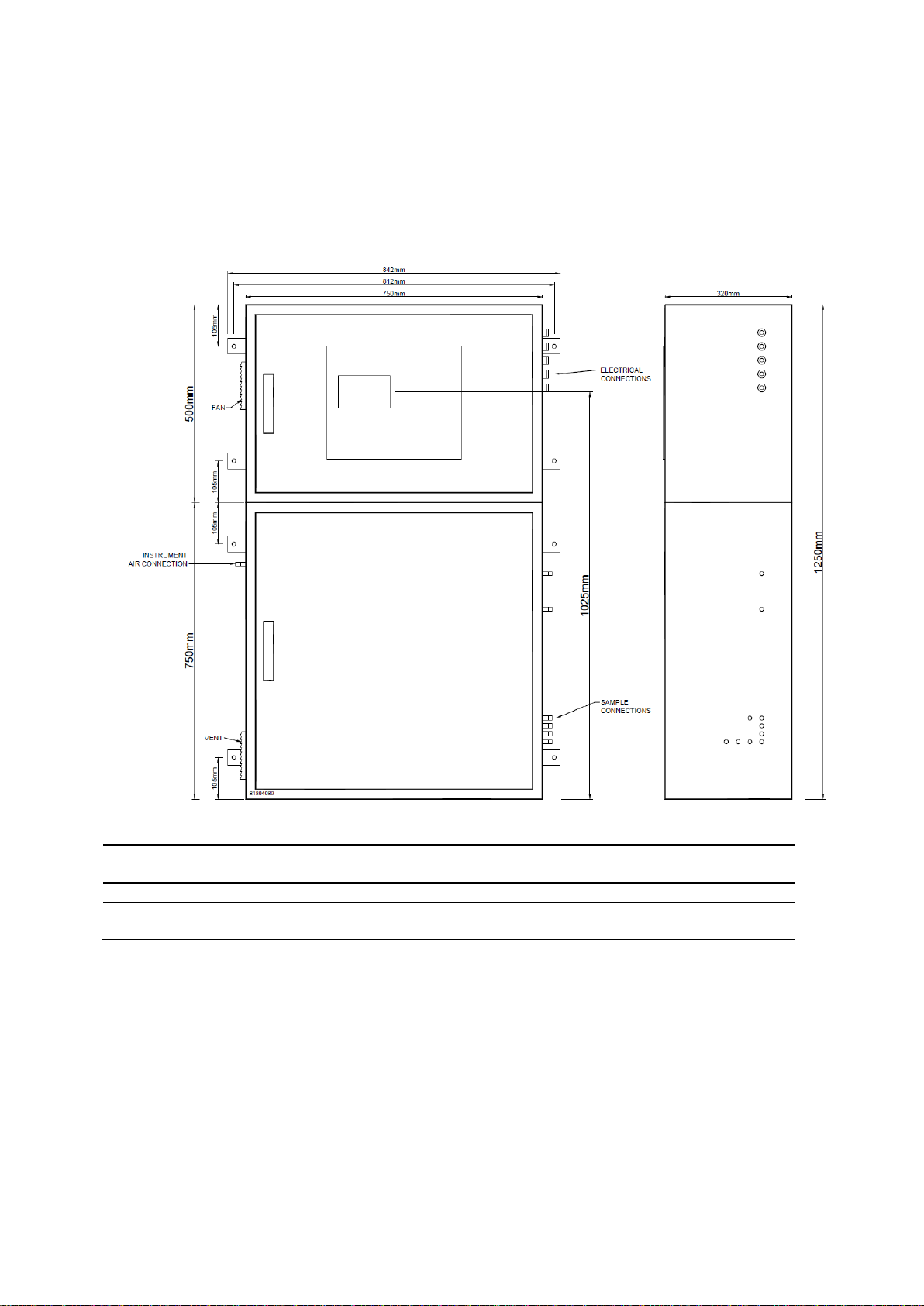
Height
Width
Height
(LCD Screen)
Depth
BioTector TOC Analyzer
1250mm
750mm
1025mm
320mm
BioTector TOC Analyzer with
extended lower enclosure
1500mm
750mm
1275mm
320mm
5.2.1 Analyzer Dimensions and Mounting
The BioTector TOC analyzer enclosure is a dual compartment Fiberglass Reinforced Polyester (FRP)
cabinet. This enclosure facilitates easy access to all components and thus eases the service and
maintenance procedures. Figure 7 and table 5 below gives the dimensions of various BioTector enclosures.
Figure 7 BioTector Dimensions
Table 5 Various BioTector Dimensions
Page 51
Page 52
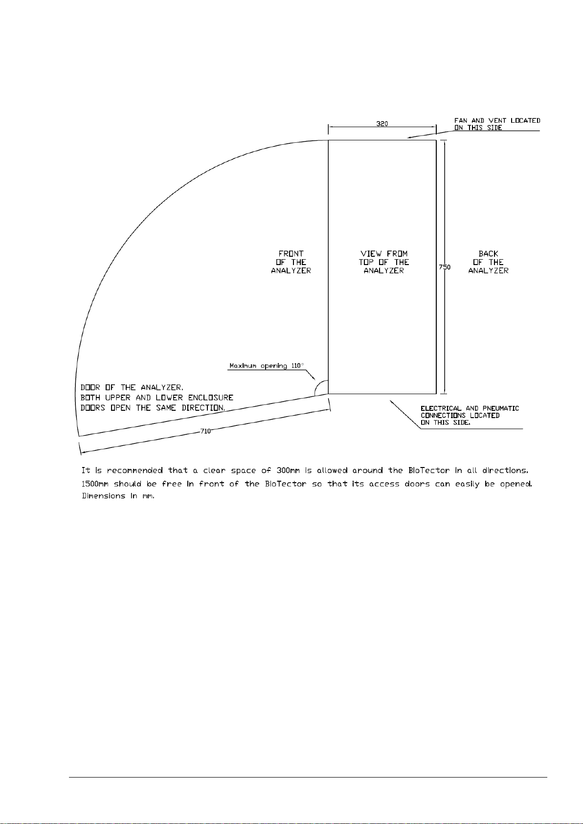
Figure 8 below illustrates the BioTector door clearance dimensions.
Figure 8 BioTector Door Clearance Dimensions
When BioTector is being mounted on a wall or a stand, the support has to be strong enough to carry
typically four times of the weight of BioTector (~400 kg).
The BioTector should be lifted applying a safe method in accordance with local regulations.
The minimum size of the bolts used to hold the BioTector in place should be M8.
Page 52
Page 53
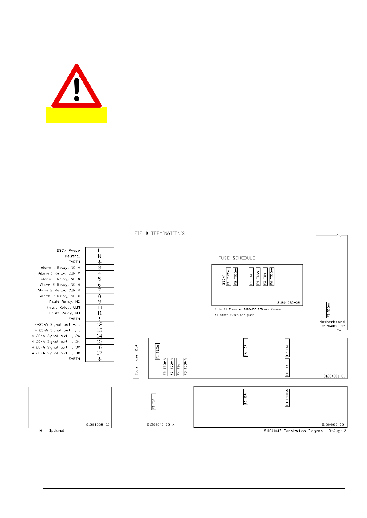
BioTector contains electrical components operating under high voltages. Contact
may result in electric shock and severe or fatal injury.
DANGER
5.2.2 Wiring Power and Signal Terminals
Figure 9 and figure 10 below show the typical mains (for both 230 and 115 volts systems respectively) and
the 4-20mA signal connections in BioTector. The connection to mains power {230V or 115V AC (10%),
50/60 Hz} should be carried out by a certified electrician, in accordance with site regulations. The mains wire
specifications are 3 cores, 10 Amps minimum current rating and 1.50mm2 minimum CSA (Cross Sectional
Area). The mains cable should be screened and screen earthed to comply with the Electromagnetic
Compatibility Directive (2004/108/EC).
For 4-20mA and any other signal connections, only screened instrument cable, which comply with the EEC
directive, should be used. The signal cable should also be screened, and the screen earthed. The
specifications for the signal wire are 8 cores (+2 cores per additional signal), 1 Amp minimum current rating,
0.22mm2 minimum CSA (Cross Sectional Area).
Figure 9 Mains and 4-20mA terminal diagram for 230 V systems
Page 53
Page 54

All electrical, sample, reagent, drain and exhaust connections should be carried out
in accordance with the technical specifications and drawings given in this manual.
Errors as a result of non-conformity to these specifications will not be covered by the
warranty.
Figure 10 Mains and 4-20mA terminal diagram for 115 V systems
The wiring and earth connections to the analyzer should be carried out in accordance with local regulations,
and securely terminated in the phase, neutral and earth terminals in the BioTector. Cable glands must be
used to secure the cables when necessary.
Page 54
Page 55

5.2.3 Wiring External Power Disconnection Switch
The mains power must be connected through an external 2-pole disconnection switch, so that the power to
the analyzer can be isolated without opening the electronics enclosure.
The external power disconnection switch must be located in an easily accessible location, with a
maximum distance of 2 meters from the analyzer.
The switch must be clearly marked for its purpose.
The switch must comply with local electrical regulations, and have a breaking capacity of 10 Amps or
greater.
Figure 11 below illustrates the positioning and the installation of the disconnection switch.
Figure 11 External Power Disconnection Switch
When the wiring of the system is completed, the power up of the system should be carried out in the order
below:
i) While the external disconnection switch is powered off, power on the internal MCB
(miniature circuit breaker) in the BioTector.
ii) Close BioTector electronics enclosure.
iii) Switch on the external disconnection switch.
The power off of the BioTector should be carried out by switching off with the external disconnection switch
followed by the internal MCB.
Page 55
Page 56

230 V
Systems
115 V
Systems
Location
Name
PCB ID
Number
Interrupt
Rating
Type
Material
Fuse
Number
Current
Rating
Current
Rating
Power PCB
(Mains PCB)
81204030-02
H-250V
Miniature
5x20mm
Ceramic
F1
T 1.25A
T 2.50A
F2
T 500mA
T 500mA
F3
T 1.00A
T 1.00A
F4
T 1.60A
T 2.50A
F5
T 2.00A
T 3.15A
F6
T 500mA
T 500mA
Relay PCB
81204001-01
L-250V
Miniature
5x20mm
Glass
F1
T 2.50A
T 2.50A
F2
T 500mA
T 500mA
F3
T 500mA
T 500mA
F4
T 1.00A
T 1.00A
F5
T 500mA
T 500mA
F6
T 1.00A
T 1.00A
F7
T 1.00A
T 1.00A
F8
T 1.00A
T 1.00A
Stream
Expansion
PCB
81204040-02
L-250V
Miniature
5x20mm
Glass
F1
T 1.00A
T 1.00A
Signal PCB
81204010-02
L-250V
Miniature
5x20mm
Glass
F1
T 1.00A
T 1.00A
F3
T 500mA
T 500mA
Main Board
(Motherboard)
81204022-04
L-250V
Miniature
5x20mm
Glass
F1
T 500mA
T 500mA
Cooler DIN
Rail
Terminal 47
L-250V
Miniature
5x20mm
Glass
F1
T 2.5A
T 2.5A
BioTector contains electrical components operating under high voltages.
Contact may result in electric shock and severe or fatal injury.
All electrical work should be carried out by qualified electrical personnel only.
When any fuse replacement is required in the system, please refer to table 6
below.
DANGER
5.2.4 System Fuse Specifications
Table 6 below summarizes the location and specification of the fuses used in BioTector. The locations of the
fuses are also displayed in figure 9 and figure 10 above.
Table 6 System Fuse Specifications
KEY A: Amperes DIN: German Institute for Standardization (Deutsches Institut für Normung e.V.)
F: Fuse H: High Interrupt ID: Identification L: Low Interrupt
mA: Milli-amperes PCB:Printed Circuit Board T: Time Lag (Time Delay)
V: Volts
Page 56
Page 57

5.3 Air Supply and Reagent Connections
The orientation of the ferrules inside each fitting of BioTector is critical for the correct operation of the system.
Incorrect ferrule orientation may create gas/liquid leak and/or introduce air bubbles into the system lines.
Therefore, the ferrules on all carrier gas, reagents, drain, exhaust and vent fittings have to be fitted with the
correct orientation. Failure to do so will have an impact on the system operation and analysis responses.
Figure 12 shows the fitting side and the nut side of SS-316 (stainless steel), PFA and PVDF fittings and their
corresponding correct ferrule orientation.
Figure 12 The correct ferrule orientation of SS-316, PFA and PVDF fittings on BioTector
When tightening brand new stainless steel fittings, first fully insert the tube into the fitting, tighten the nut
initially finger tight, then tighten a further 1¼ turns using an appropriate size spanner or an adjustable wrench.
Stainless steel fittings used on 1/8” PFA tubing should be tightened only a further ¾ turns after finger tight.
When re-tightening stainless steel fittings, which were already tightened during reassembly or after service,
initially tighten the nut up to the point it was tightened previously, then tighten slightly more using an
appropriate size spanner or an adjustable wrench.
When tightening brand new PFA fittings, first fully insert the tube into the fitting, tighten the nut initially finger
tight, then tighten a further ½ turn using an appropriate size spanner or an adjustable wrench. When retightening PFA fittings, which were already tightened during reassembly or after service, initially tighten the
nut up to the point it was tightened previously, then tighten slightly more using an appropriate size spanner or
an adjustable wrench.
Page 57
Page 58

BioTector Air Compressor can be supplied by BioTector distributors as an
option.
5.3.1 Air Supply Connection
The recommended air quality for BioTector is -20°C dew point, free of water, oil and dust. A filter pack may be
required to meet or exceed the air quality specification.
The air can be supplied to BioTector from:
A) An existing instrument air supply line
B) BioTector Air Compressor
The required instrument air supply pressure is 1.5 bars. The minimum air supply flow rate is 8.4 m3/hour at
1.5 bar. The average air consumption is less than 5.4 m3/hour, and typically 3.6 m3/hour during online
operation.
Figure 13 below illustrates the two options for air supply: A) from an existing instrument air supply line, B)
from BioTector Air Compressor.
Figure 13 BioTector air supply options
Page 58
Page 59

Special precautions are needed when working with chemical reagents, both
when renewing reagents and when dealing with leaks or spills. Some reagents
can cause chemical burns and may cause injury or death if swallowed. Please
refer to the symbols and codes on the reagent containers.
DANGER
5.3.2 Reagent Connections
Use of 25 liter containers is recommended for each BioTector reagents. Figure 14 below shows the correct
setup and connection of BioTector reagents: Acid (1.8N Sulfuric Acid) and Base (1.2N Sodium Hydroxide).
See Section 6 Reagents and Calibration Standards for further details.
Figure 14 BioTector reagent setup and connections
Page 59
Page 60
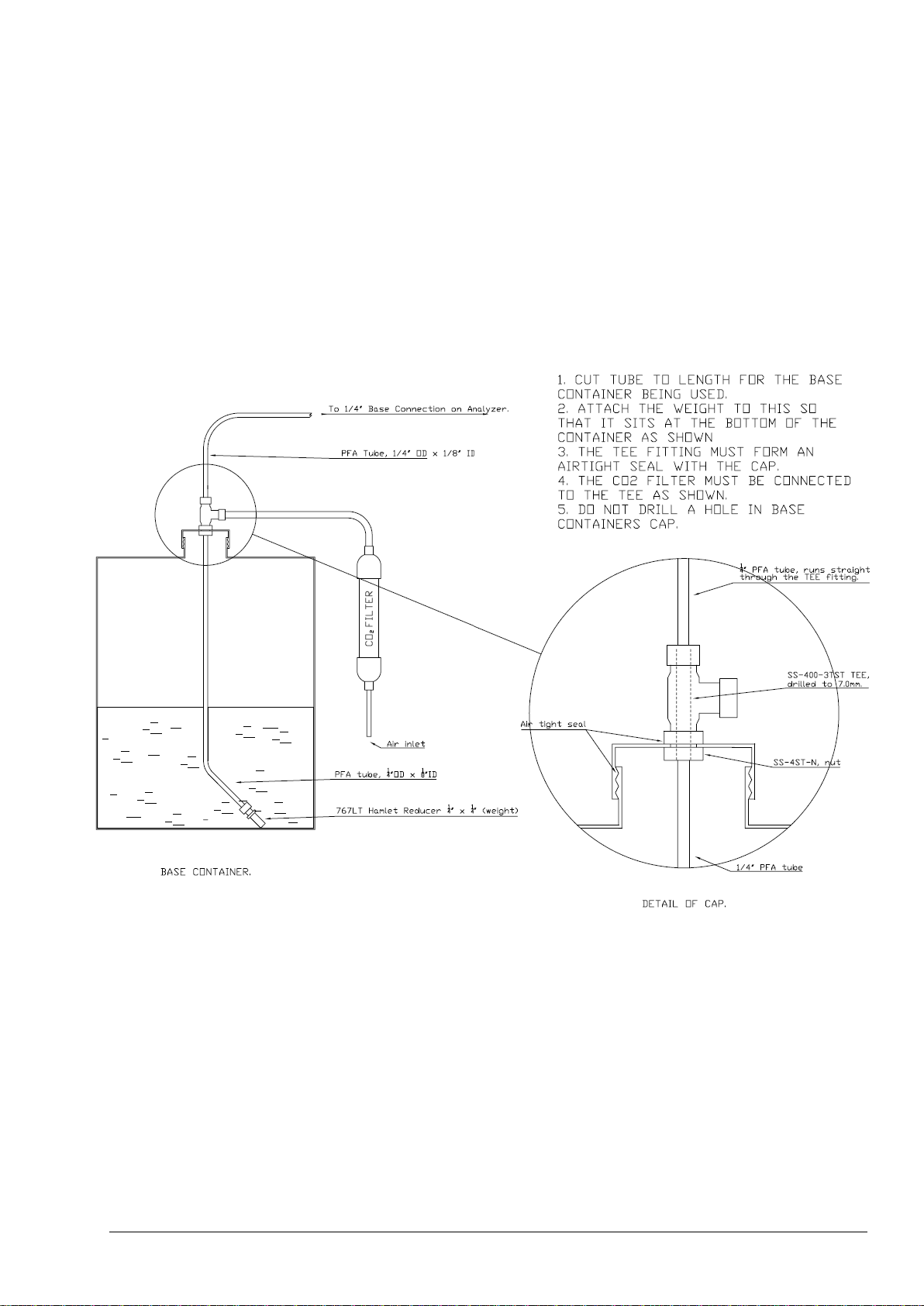
As can be seen in the figure 14 above, unlike all other reagents, base reagent container does not contain any
vent (breathing) hole. The breathing air into the base container is supplied through the CO2 filter, which must
be fitted on the base container lid.
Figure 15 below shows the detailed connections on BioTector base reagent. The purpose of the CO2 filter is
to prevent the base reagent coming in contact with atmospheric CO2 present in the air. The soda lime inside
the CO2 filter absorbs the atmospheric CO2 and prevents the base reagent getting contaminated. If any vent
hole is accidentally drilled on the lid of the base container and if the fittings are not connected correctly on the
base reagent, contamination will occur and the background CO2 readings will increase.
Figure 15 BioTector base reagent dip tube setup
All other reagent containers’ (except the base reagent container) lids must contain a 3mm vent hole. Failure
to do so may cause the container to collapse and leak.
The length of the dip tubes in all reagent containers should be adjusted correctly for the optimum usage of the
reagents. Stainless steel (SS-316) weights should not be used in any reagent which contains HCl acid. The
recommended weights for such reagents are PFA.
Page 60
Page 61
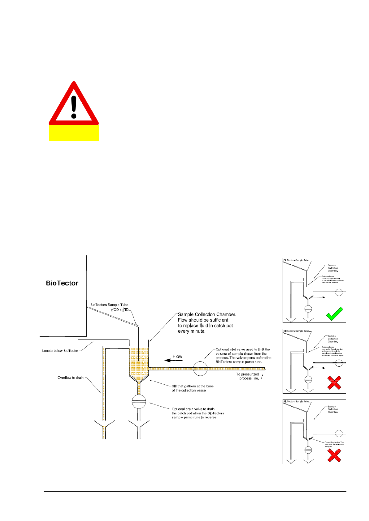
For the fittings to remain leak proof, they must be kept clean and should not be
over tightened. Over tightening of the fittings will damage them and cause
eventual leakage.
Caution
5.4 Sample, Drain and Exhaust Connections
5.4.1 Sample Inlet Tube Position
BioTector operates on unfiltered samples, the setup of the sampling point is important for the correct
operation of the system. BioTector can handle soft particulates up to 2mm in diameter, however hard
particulates (e.g. sand) will damage the analyzer and should be removed from the sample.
The vertical distance between the water surface at the sample intake and the bottom of the BioTector
enclosure can be up to 4 meters. The overall length of the sample tube is typically 4 meters. BioTector in fact
can draw samples from distances greater than 4 meters however, such distances may have an impact on the
Sample Pump tubing life. The point where the sample is taken from should not be pressurized. The sample
inlet and outlet should be at ambient pressure. The sample temperature should be between 2°C and 60°C
(36°F - 140°F). The minimum sample flow rate is 100ml per sample. The sample bypass tube should be
placed to a well ventilated area at ambient pressure and it should not be subjected to any back pressure as
this may result in measurement errors. Figure 16 illustrates the correct positioning of the BioTector sample
tube in various/optional sampling systems.
Figure 16 BioTector sample tube position in various sampling systems
Page 61
Page 62

Page 62
Page 63

The BioTector should be installed in a well-ventilated area with the exhaust port
piped to an external vent. The installation should be carried out in accordance
with Section 1 Safety Precautions.
WARNING
5.4.2 Drain, Bypass and Exhaust Connections
All BioTector drain tubing must be positioned correctly so that any liquid pumped will drip freely into a larger
drain chamber. The correct positioning and setup of the drain ports prevent liquid accumulation and
measurement errors. All drain ports should be directed to a well ventilated area as oxygen and other gases
may be released during the analysis. The drain tubes should be at atmospheric pressure and should not be
subjected to any back pressure as this may result in measurement errors. The exhaust tube should be piped
out to a well ventilated area as oxygen and other gases will be released during the analysis. The end of this
tube should be positioned in a downward position so that water condensation and freezing will not occur
during winter months. Figure 17 illustrates BioTector drains, sample bypass and exhaust connections.
The PVC-U Drain Pipe, installed outside the BioTector, is supplied for convenience. PVC-U is a durable
material, which survives in environments containing acids, caustics, oxidizing agents etc. However, if the
sample contains specific high concentration solvents such as Benzene, Toluene etc., it is recommended to
check the compatibility of PVC-U tubing against the specific organic solvents present in the sample. If
necessary, the drain pipe can be replaced with an alternative pipe. If such change is carried out, it is
important that the sample bypass port is connected to the new pressure free drain pipe at the same height
with the original pipe.
Figure 17 BioTector drain, sample bypass and exhaust connections
Page 63
Page 64

REAGENTS
Container Size
(Liters)
TOTAL DAYS REAGENT LASTS PER ANALYSIS
RANGE
0-250
mgC/l
0-2000
mgC/l
0-20000
mgC/l
Acid
25
54
34
32
Base
25
53
33
31
Section 6 Reagents and Calibration Standards
6.1 Reagents
BioTector TOC analyzer uses following reagents:
I. Acid: 1.8 N Sulfuric Acid (H2SO4) Reagent containing 80mg/l Manganese Sulfate Monohydrate
II. Base: 1.2 N Sodium Hydroxide (NaOH) Reagent
Reagents should not contain high levels of organics, nitrates and phosphates. Ideally, the level of organics,
nitrates and phosphates should be less than 100 g/l (ppb) in the deionized water used to prepare TOC
analyzer reagents.
Acid and Base reagents are stable up to 1 year. Table 7 below summarizes the total days each BioTector
TOC Analyzer reagent lasts at various system analysis range configurations:
Table 7 BioTector TOC Analyzer Reagent Consumption
Above table is derived from several operation parameters such as 100% online time. Recommended bunds
(reagent spill trays) to contain above quantity reagents are 1x 50 Liters.
Page 64
Page 65
All hygroscopic chemicals in crystal form should be dried in an oven set at 105°C for 3
hours to remove any traces of absorbed water. All prepared solutions must be mixed
thoroughly with a magnetic stirrer or inverted manually at least ten times or until all
crystals are completely dissolved inside the solution.
The quantity of concentrated chemical required to prepare stock calibration solutions
will change with the % purity of the chemical used. If the purity of the chemical is
different than the figures displayed above, the necessary quantity needs to be
recalculated from the purity of the chemical. See example in the following page.
Depending on the system analysis ranges (see System Range Data screen 2.2.3
System Range Data Screen for details), every BioTector requires specific
calibration standard solutions. The required concentration of the calibration standard
solutions can be identified in Span Calibration menu.
As the sample pressure normalization (line equalization function) is not activated for
Calibration/Manual Valve, it is recommended that the calibration standard solution flask
is placed at the same height with the Sample Pump.
Caution
Caution
6.2 Calibration Standards
The following compounds can be used to prepare calibration standard solutions in BioTector.
To prepare a 1000mgC/l Total Organic Carbon (TOC) standard solution, use one of the following:
Potassium Hydrogen Phthalate, C8H5KO4, 2.13g (99.9% purity) in one liter of deionized water. Water
solubility: 80 g/L at 20°C.
Acetic acid, C2H4O2, 2.51g (99.8% purity) in one liter of deionized water. Water solubility: Miscible in
all proportions.
Glucose, C6H12O6, 2.53g (99% purity) in one liter of deionized water. Water solubility: 512g/L at 25°C.
To prepare a 1000mgC/l Total Inorganic Carbon (TIC) standard solution, use one of the following:
Sodium Carbonate, CNa2O3, 8.84g (99.9% purity) in one liter of deionized water.
Sodium Hydrogen Carbonate, CHNaO3, 7.04g (99.5% purity) in one liter of deionized water.
Potassium Carbonate, CK2O3, 11.62g (99.0% purity) in one liter of deionized water.
Page 65
Page 66

% Purity of KHP
Quantity of KHP (grams)
to prepare 1000 mgC/l Standard
100
2.127
99.9
2.129
99.5
2.138
99.0
2.149
95.0
2.239
90.0
2.364
TOC Standard Solution
Concentration (mgC/l)
Quantity of 99.9% KHP (grams)
to be added into 1 Liter DIW
1000
2.129
1250
2.661
1500
3.194
2000
4.258
5000
10.645
10000
21.290
The calculation of the quantities required to prepare Potassium Hydrogen Phthalate (KHP) standard solutions
with various purities are given as an example below:
Name: Potassium Hydrogen Phthalate
Formula: C8H5KO4
Carbon, 12 x8 = 96
Oxygen, 16 x4 = 64
Potassium, 39 x 1 = 39
Hydrogen, 1 x5 = 5____________
Total weight = 204.22 g/mol
47% of KHP is Carbon. Purity of the KHP is 99.9%. Therefore, to prepare a 1000 mgC/l standard solution,
add 2.13g of KHP in a flask and add enough deionized water to make it exactly 1 liter solution.
Note that the quantities required change with the % purity of the chemical used. Table 9 below gives the KHP
quantities required at various % purity for the preparation of 1000mgC/l calibration standard.
Table 9 Quantity of KHP required to prepare 1000 mgC/l standard at various purities.
To prepare standard solutions containing more than 1000 mgC/l, the required solvent can be mixed directly
with deionized water. Table 10 below gives the required quantity of KHP for various concentration standard
solutions to be mixed with deionized water and added enough deionized water to make the solution exactly 1
liter.
Table 10 Quantity of KHP required to prepare various concentration TOC standard solutions.
Page 66
Page 67

Use eye protection and gloves.
Preparation of Calibration Standard Solutions:
Standards solutions greater than 1000mg/l can be prepared directly without any dilution by simply mixing the
necessary quantity solvent or salt with deionized water. Standard solutions below 1000mg/l concentration
should be prepared by dilution technique. First a 1000mg/l standard stock solution should be prepared, and
then the required lower concentration standard solution should be prepared by applying the necessary dilution
procedures:
For example, to prepare a 50mgC/l TOC only standard solution, first weigh 50 grams of the
1000mgC/l stock standard. Add 50 grams of the 1000mgC/l standard into a one-liter flask and add
enough deionized water to make the solution exactly 1 liter.
For increased accuracy, standard solutions below 5mg/l (ppm) concentration should be prepared with
two or more steps dilution. For example, to prepare a 1mgC/l standard, first prepare a 100mgC/l
standard by adding 100 grams of the 1000mgC/l standard into a one-liter flask and by adding enough
deionized water to make it exactly a 1 liter solution. Then add 10 grams of the 100mgC/l standard into
a one-liter flask and add enough deionized water to make it exactly 1 liter.
Standard solutions at μg/l (ppb) levels should be prepared with several dilution steps. For instance, a
1mgC/l (1000 μg/l) standard should be prepared with two or more steps dilution as described above.
To prepare a 50μg/l standard, add 50 grams of the 1000μg/l standard into a one-liter flask, and add
enough deionized water to make it exactly 1 liter.
Shelf Life and Storage of Calibration Standard Solutions:
TOC standards prepared from Potassium Hydrogen Phthalate is typically stable for a month once it
is kept in a closed glass container and refrigerated at 4°C.
All other standards such as TOC prepared with Acetic Acid and TIC standards are recommended to
be used within 48 hours of manufacture.
Page 67
Page 68

For system and personal safety, refer to Section 1 Safety Precautions. Necessary
safety precautions, such as wearing eye protection and gloves, should be taken throughout the
commissioning and startup procedures.
_____
1. INSPECTION and SYSTEM CONNECTIONS:
Several tubing are disconnected and labeled in BioTector for shipping. Before connecting any
tubing, inspect the analyzer. Check all the electrical and tubing connections and confirm that there
are no loose connections within the BioTector. Close the analysis door.
_____
Reconnect the tube linking the Ozone Generator to the acid TEE, at the TEE.
Reconnect the tube linking the Cooler and CO2 analyzer, at the top of the Cooler.
Reconnect the tube linking the Ozone Destructor to the Exhaust Valve (MV1), at the top of
the Ozone Destructor.
_____
The Acid and Base pump tube rails and the tubing of pumps are disconnected and labeled in
BioTector for shipping. Reconnect the tube rails and install the pump tubing of the Sample, Acid
and Base pumps.
_____
Check the Swagelok / PFA tube connections and confirm there are no loose connections within
the BioTector.
_____
Check the electrical connections and confirm there are no loose connections within the BioTector.
_____
Confirm the mains supply voltage and the frequency on site match the analyzer requirements.
Connect the power cable.
_____
Connect the 4-20mA cables.
_____
Connect low voltage wiring (e.g. Fault Relay).
_____
Connect the air supply to the BioTector’s AIR port. See figure 13 in Section 5.3.1 Air Supply
Connection for details. The minimum air supply flow rate is 8.4 m3/hour at 1.5 bar. The average air
consumption is less than 5.4 m3/hour, and typically 3.6 m3/hour during online operation. When the
oxygen concentrator is running, the pressure typically cycles from 1.5 bar to 0.9 bar.
Option A: Instrument air. The set point pressure of the air, supplied from an existing
instrument air supply line, should be 1.5 bar. The recommended air quality
is -20°C dew point, free of water, oil and dust.
Option B: BioTector Compressor. The set point air pressure supplied from BioTector
compressor should be 1.5 bar.
In BioTectors built with a vortex cooler, air should be supplied to the vortex cooler using a
regulator, which is dedicated for the vortex cooler only.
_____
Connect the EXHAUST port with ¼” PFA tube to a safe and well ventilated area or to open
atmosphere. The tube must have no restrictions and it must be placed so that any condensation
and liquid buildup in the tubing is prevented. The maximum length of ¼” PFA tubing installed in
Exhaust line is 10 meters. If tubing longer than 10 meters is required, the use of a larger ID tubing
or pipe is recommended.
The end of the exhaust tubing should have a slight downward slope so that any condensation or
liquid at the outlet of the tubing cannot freeze at night or during cold weather. See figure 15 in
Section 5.4.2 Drain, Bypass and Exhaust Connections for details.
_____
Remove the tapes, which are used to seal the ends of the supplied CO2 filter. Fit the CO2 filter to
the Base container and seal the Base container tightly. See figure 14 and figure 15 in Section
5.3.2 Reagent Connections for details.
_____
Section 7 Analyzer Commissioning and Startup
The check list below must be used to ensure that the installation has been properly carried out. Please
proceed through the check list in the given order, completing the 5 sections below. Detailed commissioning
and startup procedures are available in presentation format in the MMC/SD card shipped with the BioTector.
It is recommended to review this document before starting the commissioning and startup procedures. If the
BioTector analyzer is certified for hazardous areas, carefully read the hazardous area documentation supplied
with the analyzer. This documentation contains important information for compliance with explosion protection
regulations. Understanding this information is essential for the safe operation of the equipment.
Page 68
Page 69

Connect the Acid (1.8N Sulfuric Acid, H2SO4, containing 80 mg/l Manganese catalyst) and Base
(1.2N Sodium Hydroxide, NaOH) containers to the BioTector’s ACID and BASE ports with ¼” PFA
tube. 20 or 25 liter containers are recommended. Confirm that weight fittings supplied are installed
at the end of the acid and base reagent dip tubes.
_____
Confirm the sample or samples are supplied to the analyzer and are at ambient pressure. See
examples in figure 16 in Section 5.4.1 Sample Inlet Tube Position for the correct positioning of
the BioTector sample tube in various sampling systems.
If a sample is under pressure, then the system must be designed to isolate the sample in the
event of a tube leak within the BioTector, for example a system consisting of a liquid leak detector
and automatic isolation valve (which must be located outside the BioTector) must be installed.
Note that the maximum allowed sample pressure is 500mbar.
_____
Referring to typical examples in figure 16 in Section 5.4.1 Sample Inlet Tube Position,
connect the sample or samples to the BioTector with ¼” PFA tube. These ports are marked
SAMPLE 1, SAMPLE 2, …, SAMPLE 6.
_____
If a BioTector SAMPLER has been supplied with the system, connect the sampler in accordance
with the drawings and instructions in the sampler manual.
_____
Connect the PVC-U Drain Pipe (installed outside the BioTector) to a well ventilated pressure free
drain using the supplied 1 inch braided hose. See figure 17 in Section 5.4.2 Drain, Bypass
and Exhaust Connections for details.
_____
Confirm that the SAMPLE OUT port is connected to a well ventilated pressure free drain with ¼”
PFA tube. The tube should be fitted so that it cannot freeze in cold weather. See figure 17 in
Section 5.4.2 Drain, Bypass and Exhaust Connections for details.
_____
Confirm the sample BYPASS port is connected to the PVC-U Drain Pipe. If the PVC-U Drain Pipe
is not used, connect the sample BYPASS port with ¼” PFA tube to a large diameter tube, as
shown in drawing 81104041. The end of the sample bypass tube should be level with the center of
the Sample (ARS) Valve. The large diameter tube should be connected to a pressure free drain.
The end of the sample bypass line should not be under the surface of the water in the drain at any
time. The tube should be fitted so that it cannot freeze in cold weather. See figure 17 in Section
5.4.2 Drain, Bypass and Exhaust Connections for details.
_____
If fitted, connect ¼” PFA tube to the MANUAL or CALIBRATION ports. Remove all tapes placed
around the fittings for shipment.
_____
If the BioTector is supplied as a “purge ready” system (i.e. if the BioTector is supplied without any fan and
vent ports), connect the -20°C dew point, oil, water and dust free purge air to the BioTector. The
purge air is instrument air which is typically at 100 L/min flow, and filtered with a 40 microns or
smaller filter. Drill and connect the air inlet port to the top left hand side of the upper enclosure.
Drill and install an air outlet port “vent” to the bottom left hand side of the lower enclosure.
_____
2. POWER UP:
Power up the analyzer. Go to Operation, Time & Date menu and adjust the time and the date.
_____
Using the Simulate menu (see Section 8.1.2 Simulate), check the following:
Confirm that the Exhaust, Sample Out and TOC Acid Valves are working.
_____
Confirm that the Sample (ARS) Valve is working.
_____
If installed, confirm that all other valves (e.g. multi-stream valve) are working.
_____
Page 69
Page 70

Check the air supply pressure. The set point pressure should be 1.5 bar. When the oxygen
concentrator is running, the pressure typically cycles from 1.5 bar to 0.9 bar. Check the O2
PRESSURE SENSOR in O2-Controller Status menu. The pressure should be between 390 mbar
and 400 mbar at the idle 1 l/h “Mass Flow Controller” MFC FLOW. At 60 l/h MFC SETPOINT flow,
the pressure should not be less than 320 mbar. See Section 8.1.6 Oxygen Controller Status
for details.
_____
Oxygen Purity Test: Power up the system for at least 10 minutes before the oxygen purity test is
carried out. Using the Simulate menu (see Section 8.1.2 Simulate) set the MFC (see figure 2 and
table 2 in Section 4.1.1 Analysis Enclosure) flow to 10 l/h and flow oxygen gas through the CO2
analyzer for 5 minutes. At the end of this period, the CO2 analyzer zero reading (ppm CO2) should
be typically within ±0.5% of full scale of the CO2 analyzer range. For instance, if the CO2 analyzer
range is 10000ppm, then the CO2 analyzer zero reading should be typically within ±50ppm.
(If the CO2 analyzer zero reading is outside the specifications, confirm that there is no CO2 in the oxygen gas
by connecting the CO2 filter “used with the sodium hydroxide reagent container” between the Cooler and CO2
analyzer inlet port and set the MFC to 10 l/h. As the size of the CO2 filter is small, keep the 10 l/h gas flow
running for at least for 5 minutes and record the CO2 zero readings at the end of the 5 minute period. If the
CO2 zero readings do not drop significantly with the CO2 filter in place, this will indicate that there is no CO2
contamination in the oxygen supply.)
_____
3. PUMP TESTS:
Caution! Below procedures involves handling strong acid and base reagents. Necessary safety precautions,
such as wearing eye protection and gloves, should be taken throughout these tests.
Go to Zero Calibration menu and select RUN REAGENTS PURGE function to prime the pumps.
The factory Reagents Purge settings to prime reagents typically cover ~3 meters distance
between the reagent containers and the BioTector. If it is necessary to increase the reagent purge
times, see section 8.3.4.5 Reagents Purge for details.
_____
Remove the nut at the T fitting located between the Mixer Reactor and the Sample Out Valve. See
figure 4 in Section 4.2.2 BioTector Sample Injection for details. Place a small container under the
reactor and place the open end of the tubing coming from the reactor into the container to capture
any possible liquid discharged. Confirm the Acid Pump is pumping correctly by using a 10ml
graduated cylinder placed under the open end of the T fitting. Activate the Acid Valve and run the
Acid Pump in Simulate menu. Acid Pump rate for SR25 Pump at 20 pulses should be between
3.9ml and 4.9ml in ~13 seconds. (Depending on the quantity of the liquid injected into the reactor and due
to an internal system interlock, the system may request the activation of Reactor Purge cycle to purge any
excess liquid from the reactor. If necessary run “REACTOR PURGE” function in the same menu.)
_____
Confirm the Base Pump is pumping correctly. Activate the Base Valve and run the Base Pump in
Simulate menu. Base Pump rate for SR25 Pump at 20 pulses should be between 3.9ml and 4.9ml
in ~13 seconds. Reconnect the tubing and the fitting.
_____
Important Note: For the correct operation of the system, the measured Acid and Base Pump rates must be
identical or similar. The maximum allowable difference in the measured volumes for acid and base injections
above should not be more than 0.2ml.
Confirm the WMM60 Sample Pump is pumping correctly. The pump rate at 16 pulses should be
between 5.5ml and 7.5ml in ~8 seconds. (Any variation between these pumped volumes is corrected
when the zero and span calibration is carried out.)
_____
Page 70
Page 71

4. COMMISSIONING MENU SETTINGS:
Using the Commissioning menus (see Section 8.2 COMMISSIONING MENU), follow below
procedures to set up the BioTector for specific site requirements:
In Reaction Time menu, program the INTERVAL time depending on the required sample analysis
frequency.
_____
In Sample Pump menu, set the correct Sample Pump FORWARD and REVERSE times. These
times are unique for each site depending on the distance between the sample and the BioTector.
Sample Pump times can be set individually for each stream in the Sample Pump menu. Adjust the
Sample Pump FORWARD times and confirm that sample liquid coming from each stream
bypasses the system and drips into the drain.
In order to establish the required Sample Pump forward and reverse times, go to Simulate menu
and run SAMPLE PUMP reverse (REV) and confirm that the sample tube is completely empty.
Run SAMPLE PUMP forward (FWD) and measure the time (in seconds) required for a fresh
sample to fill and flow out through the bypass port. Add 10 seconds to the measured time and
enter this value as the FORWARD time in the Sample Pump menu. The sample pump REVERSE
time will be automatically set as 15 seconds greater than the FORWARD time.
_____
Go to Process Test, Sample Pump Test menu and select the PUMP FORWARD TEST and PUMP
REVERSE TEST functions to confirm that the programmed sample pump times are correct to
properly fill and empty the sample tube of each stream.
_____
If the BioTector SAMPLER is used, then the default sampler time is 100s. This default time must
not be changed unless the time programmed in the PLC of the sampler is also changed. See
BioTector Sampler User Manual for details.
_____
In Stream Program menu, set the required multi-stream parameters (stream operation sequence,
number of reactions to run at each stream and operation range for each stream). Automatic range
change function should not be used in multi-stream systems.
_____
In COD/BOD/LPI/FLOW program menu, if COD/BOD/LPI and/or FLOW parameters are required,
program DISPLAY with the required parameter. Install the relevant STREAM, TOC FACTOR, LPI
VALUE, HEADING for applicable streams, and the full scale of sample flow meter analog input
signals for STREM 1-3. See Section 8.2.4 COD/BOD/LPI/FLOW Program for details. If
required, the factors for each stream can be obtained following the procedures described in information sheet
“I030. TOC to COD or BOD Correlation Method”, which is available in the MMC/SD card shipped with the
BioTector.
_____
In New Reagents Program menu, confirm the factory settings are suitable for site requirements.
_____
In Reagents Monitor menu, if required, activate/deactivate the reagent monitoring function,
program the reagent volumes and set the relevant reagent warnings.
_____
In Autocal Program menu, if required, program the automatic zero and span calibration cycles.
_____
In 4-20mA Program menu, set the required parameter for each stream. Set the full scale
concentration level for each 4-20mA channel. Full scale should be compatible with the external
process control device (e.g. DCS) and BioTector calibrated ranges. In order to see BioTector
calibrated ranges, see System Range Data screen (2.2.3 System Range Data Screen) and Stream
Program menu (8.2.3 Stream Program).
_____
In Alarm Program menu, set the available relays to the required ALARM levels for each stream. If
necessary, to modify the relay parameters and conditions, go to Output Devices menu. See
section 8.3.5 Output Devices for details.
_____
In Data Program menu, if required, program the relevant configuration parameters for the specific
output device communication port.
_____
Page 71
Page 72

Go to Signal Simulate menu and test 4-20mA signals. Simulate 1mA, 4mA, 12mA and 20mA
signals and confirm that the signals are received by the external process control device (e.g.
DCS). Simulate all digital input and output signals and confirm correct operation.
_____
5. ZERO and SPAN CALIBRATION:
Go to Operation, Reagents Setup, Install New Reagents menu, confirm the menu items and select
the “START NEW REAGENT CYCLE” function for the system to prime the reagents and set the
Zero Adjust (zero offset) values automatically. See Section 2.2.2.1 Install New Reagents
and 8.2.5 New Reagents Program for details.
_____
Observe that the automatic pressure/flow test passes when analyzer is started up. See Section
2.1.3 Analysis Data Screen and 8.3.4.6 Pressure/Flow Test Program for details.
_____
It is recommended to check the zero response. When the Zero Calibration cycle is completed, go
to Operation, Start Stop menu (see Section 2.2.1 Start Stop for details) and stop the
analyzer. Go to Zero Calibration menu and select RUN ZERO CHECK function. Alternatively, to
confirm that the zero response is correct, connect DIW to the manual sample port and run 5
analysis cycles on DIW using the Manual Program menu. (If manual port is not available, use the input
point for SAMPLE 1. If the BioTector has been in storage for a long period, and if the zero readings are not
satisfactory, a second “Install New Reagents” cycle may be required.)
_____
If the zero readings and CO2 peaks are correct, items from 1 to 6 below can be skipped.
_____
1
Confirm that the pH in the reactor is correct, using the test sequence in the pH Test menu. See
Section 8.1.1.5 pH Test for details.
_____
2
Check for a pH of <2 during the TIC phase.
_____
3
Check for a pH of >12 during the Base Oxidation phase.
_____
4
Check for a pH of <2 during the TOC phase.
_____
5
Run a further 2 reactions on DIW.
_____
6
Run an “Install New Reagents” cycle on the system to adjust the zero offset.
_____
Program the concentration of the standard solution in the Span Calibration menu (2.3.2 Span
Calibration). The concentration of the calibration standard used must be typically greater than 50%
of the full scale of the RANGE the calibration is carried out. In order to see BioTector calibrated
ranges, see System Range Data screen (2.2.3 System Range Data Screen). (To prepare a
standard solution, see procedures described in Section 6.2 Calibration Standards or information sheet
“R009. Standard Solutions for BioTector Multi-component Analyzer”, which is available inside the MMC/SD
card shipped with the BioTector.)
_____
Connect the standard solution to the MANUAL/CALIBRATION port. If these ports are not
available, use the SAMPLE 1 port. Avoid the manual purging of the calibration, manual grab
sample and sample lines using the Simulate menu, because the system reactor may get
contaminated during the automatic sample valve and pump synchronization process. To purge
these lines, it is recommended to use PUMP FORWARD TEST and PUMP REVERSE TEST
functions in the Sample Pump Test menu (see 8.1.1.4 Sample Pump Test for details). It is
recommended that the standard solution is located at the same height as the sample pump. Run
the Span Calibration cycle using the RUN SPAN CALIBRATION function in Span Calibration
menu. A minimum of five complete analysis cycles is recommended for the span calibration.
_____
Download BioTector “All Data” in text format into the MMC/SD card using the SEND ALL DATA
function in Data Output menu to record all changes made in the system configuration. See Section
8.1.4 Data Output for details.
_____
Go to Start Stop menu and start the BioTector. When the BioTector is running online, carefully
observe the first two or three reactions and confirm that the CO2 peaks are correct.
_____
Page 72
Page 73

Section 8 Maintenance Menu
Maintenance Menu Diagram
Page 73
Page 74

8.1 DIAGNOSTICS MENU
This group of menu allows the user to access the Process Test, Simulate, Data Output, Input/Output Status
and Service menus for diagnostic purposes.
Diagnostics Menu Diagram
Page 74
Page 75

P R E S S U R E T E S T 0 9 : 1 7 : 2 8 1 2 - 0 9 - 0
2
1 < * P R E S S U R E T E S T
2 P R E S S U R I Z E R E A C T O R T I M E 6 0 s M F C S E T P O I N T 4 0 . 0 l / h M F C F L O W 0 3 . 3 l / h
S T A T U S T E S T I N G P R E S S E S C T O A B O R T T H E T E S T
8.1.1 Process Test
This group of menus allows the user to simulate the Pressure Test, Flow Test, Ozone Test, Sample Pump
Test, pH Test and Sample Valve Test routines.
Detailed Process Test procedures are available in the MMC/SD card shipped with the BioTector. It is
recommended to review these documents for troubleshooting purposes when necessary.
8.1.1.1 Pressure Test
This menu enables the user to simulate the Pressure Test. The menu also shows the current status of the
Mass Flow Controller. Any settings made by the user in this menu are automatically reset when the user exits
this menu.
1. Pressure Test. Use this function to simulate the Pressure Test. When the Pressure Test is activated, an
“*” will be shown, and a small menu will display the following data:
Time: The time for the pressure test is 60 seconds. This time shows the time left to the end
of the test.
MFC Setpoint: This is the BioTector mass flow controller flow setting (40 l/hr by default) for the
pressure test.
MFC Flow: This is the actual flow from the mass flow controller. Initially the setpoint and flow will
match, and if there is no gas leak, after about 25 seconds the flow will fall to close to
zero.
Status: At the end of the test, the status below is shown:
TESTING: Test in progress.
PASS: The Pressure Test finished its cycle with a flow below the Pass
(Pressure Test Warning) level (4 l/hr by default).
WARNING: The Pressure Test finished its cycle with a flow above the Pass
(Pressure Test Warning) level, but below the Fail (Pressure Test
Fault) level (6 l/hr by default).
FAIL: The Pressure Test finished its cycle with a flow above the Fail
(Pressure Test Fault) level (6 l/hr by default). See Section 8.3.4.6
Pressure/Flow Test Program for details.
2. Pressurize Reactor. This is similar to the Pressure Test above, but its time has been extended to 999s,
allowing the user to locate any leak there may be on the system. Pass, Warning and Fail are
automatically shown on the screen, depending on the status of the test.
Page 75
Page 76

F L O W T E S T 0 9 : 1 7 : 2 8 1 2 - 0 9 - 0
2
1 < * E X H A U S T T E S T 2 E X H A U S T F L O W 3 S A M P L E O U T T E S T 4 S A M P L E O U T F L O W
T I M E 3 0 s
M F C S E T P O I N T 8 0 . 0 l / h M F C F L O W 7 8 . 3 l / h S T A T U S T E S T I N G P R E S S E S C T O A B O R T T H E T E S T
8.1.1.2 Flow Test
This menu enables the user to simulate various Flow Tests through the system. The menu also shows the
current status of the Mass Flow Controller. Any settings made by the user in this menu are automatically reset
when the user exits this menu.
1. Exhaust Test. Use this function to simulate the flow through the Exhaust Valve. When the Exhaust Test
is activated, an “*” will be shown, and a small menu will display the following data:
Time: The time for the flow test is 30 seconds. This time shows the time left to the end of
the test.
MFC Setpoint: This is the BioTector mass flow controller flow setting (80 l/hr by default) for the flow
test.
MFC Flow: This is the actual flow from the mass flow controller. If there is no blockage in the
lines, then the setpoint should match the flow.
Status: At the end of the test, the status below is shown:
TESTING: Test in progress.
PASS: The Exhaust Test finished its cycle with a flow above the Pass (Flow
Warning) level (72 l/hr by default). See Section 8.3.4.6
Pressure/Flow Test Program for details.
WARNING: The Exhaust Test finished its cycle with a flow below the Pass level
(less than 72 l/hr), but above the Fail level (greater than 40 l/hr).
FAIL: The Exhaust Test finished its cycle with a flow below the Fail level
(40 l/hr by default).
2. Exhaust Flow. This is similar to the Exhaust Test menu, but its time has been extended to 999s, allowing
the user to locate any blockage in the system. Pass, Warning and Fail are automatically shown on the
screen, depending on the status of the test.
3. Sample Out Test. This is similar to the Exhaust Test. This function allows the user to test the flow
through the Sample Out Valve.
4. Sample Out Flow. This is similar to the Exhaust Flow. This function allows the user to test the flow
through the Sample Out Valve.
Page 76
Page 77

The ozone test uses the procedure described in information sheet “T021.
Procedure to check the ozone level in BioTector with Mixer Reactor”, which is
available in the MMC/SD card shipped with the BioTector. The user must read
and understand the processes described in this sheet, and have all the correct
parts listed before carrying out the test.
Ozone will be generated when the ozone generator is turned on.
O Z O N E T E S T 0 9 : 1 7 : 2 8 1 2 - 0 9 - 0
2
1 < * S T A R T T E S T
2 S T O P T E S T
P R E S S U R E T E S T 0 9 : 1 7 : 2 8 1 2 - 0 9 - 0
2
T I M E 3 5 s M F C S E T P O I N T 4 0 . 0 l / h M F C F L O W 2 2 . 0 l / H
S T A T U S T E S T I N G
P R E S S E S C T O A B O R T T H E T E S T
WARNING
8.1.1.3 Ozone Test
General overview of the operation of the ozone test:
Phase 1: Install the tester according to information sheet T021, and start the test from the menu.
Phase 2: The BioTector carries out a pressure test, to ensure that the system is leak tight.
Phase 3: The ozone generator is switched on, and when the o-ring in the tester breaks, press the stop
test menu item.
Phase 4: There is a purge period that purges any traces of ozone from the ozone tester, and the result
of the test is shown on the screen.
Phase 5: The purge of the tester is complete, and the result remains on the screen.
Ozone Test, Phase 1:
This menu enables the user to test the concentration of ozone generated by the BioTector.
1. Start Test. This starts the ozone test.
2. Stop Test. This stops the ozone test. It should be activated when the o-ring in the tester breaks, or at any
time to stop the ozone test.
Ozone Test, Phase 2:
This menu enables the user to monitor the progress of the ozone test. To abort the ozone test, press the
ESCAPE key on the keyboard.
Page 77
Page 78

O Z O N E T E S T 0 9 : 1 7 : 2 8 1 2 - 0 9 - 0
2
1 * S T A R T T E S T 2 < S T O P T E S T T I M E 5 s S T A T U S T E S T I N G O Z O N E G E N E R A T O R I S O N ! ! ! D O N O T O P E N O Z O N E T E S T E R
O Z O N E T E S T 0 9 : 1 7 : 2 8 1 2 - 0 9 - 0
2
1 S T A R T T E S T 2 < * S T O P T E S T T I M E 1 2 s
S T A T U S P A S S D O N O T O P E N O Z O N E T E S T E R U N T I L P U R G E O F O Z O N E T E S T E R C O M P L E T E
O Z O N E T E S T 0 9 : 1 7 : 2 8 1 2 - 0 9 - 0
2
1 S T A R T T E S T
2 < * S T O P T E S T T I M E 1 2 s S T A T U S P A S S
Ozone Test, Phase 3:
The ozone test has now started. DO NOT OPEN THE OZONE TESTER. The user should now move the
cursor down to line 2, and press the ENTER key as soon as the o-ring in the ozone tester breaks. The time
will be calculated automatically.
Ozone Test, Phase 4:
When the o-ring breaks, immediately select Stop Test and press the ENTER key. The ozone generator is now
switched off, but there will still be traces of ozone in the tester. Therefore the BioTector will purge the tester
for 30s to remove these traces of ozone. DO NOT OPEN THE OZONE TESTER until the warning message is
removed.
The time for the o-ring to break is shown on the screen, as well as the PASS, LOW OZONE or FAIL
message. Note that the maximum allowed time for the ozone test is 60s, after which the FAIL message is
displayed.
Ozone Test, Phase 5:
The test is complete. The time for the o-ring to break is shown on the screen, as well as the PASS, LOW
OZONE or FAIL message. The Pass, Low Ozone or Fail setting is factory set in the Fault Setup menu.
Page 78
Page 79

S A M P L E P U M P T E S T 0 9 : 1 7 : 2 8 1 2 - 0 9 - 0
2
1 V A L V E S T R E A M 1 2 < * P U M P F O R W A R D T E S T 3 P U M P R E V E R S E T E S T 4 5 - - > S A M P L E P U M P
T I M E 6 s S T A T U S T E S T I N G P R E S S E S C T O A B O R T T H E T E S T
8.1.1.4 Sample Pump Test
This menu enables the user to test the Sample Pump forward and reverse times. Any settings made by the
user in this menu are automatically reset when the user exits this menu.
1. Valve. Valve allows the user to select the stream or manual sample ports the Sample Pump Test is going
to be carried out. The valve selection may have an effect on the Sample Pump forward time measured
with the Pump Forward Test below, unless all sample lines are at the same length.
2. Pump Forward Test. This function starts the Sample Pump running in the forward direction. When the
sample has been correctly transported to the BioTector, through the Sample (ARS) Valve and as far as
the recommended sample transport point or until it drips out into the drain, press ESCAPE. This stops the
timer, and provides the user the correct FORWARD times to be programmed for each stream and manual
sample in the Sample Pump menu (see Section 8.2.2 Sample Pump for details).
3. Pump Reverse Test. This is the same as the Pump Forward Test above, only this time Sample Pump
operates reverse to empty the sample lines and the oxidized sample catch-pot/cleaning vessel (if
installed) back into the corresponding stream selected with the Valve above.
5. Sample Pump. Sample Pump is a link to the Maintenance, Commissioning, Sample Pump menu (see
Section 8.2.2 Sample Pump for details).
Page 79
Page 80

The user must understand the procedure for testing the pH in the BioTector.
Use eye protection and gloves. Have all the relevant parts for this test ready
(primarily beaker and pH paper) before carrying out the test.
For the pH test to be accurate, the previous reaction should have finished
normally, so that any liquid carried over from that reaction will not affect the pH
test.
Significant volume of liquid loss, during the pH test phases 1, 2, 3 or 4
described below, have an impact on the consecutive pH tests. Therefore, it is
strongly recommended that the test is stopped upon completion of each
specific phase, where the volume of liquid is lost, and re-started from pH Test
Phase 1 below. When the pH test is re-started, the corresponding pH
measurements can be skipped for the previous valid tests.
P H T E S T 0 9 : 1 7 : 2 8 1 2 - 0 9 - 0
2
1 < R A N G E , V A L V E 1 , S T R E A M 1 2 M O D E T I C + T O C
3 S T A R T T E S T
4 T A K E S A M P L E 5 C O N T I N U E T O N E X T P H A S E 6 S T O P T E S T
WARNING
8.1.1.5 pH Test
General overview of the operation of the pH test:
The description below is for the TIC & TOC analysis mode. In systems built with TC and VOC analysis
modes, BioTector automatically carries out the corresponding operation phases as described in Sections
4.2.4.2 TC Analysis and 4.2.4.3 VOC (POC) Analysis respectively.
Phase 1: Prepare the test equipment, and start the test.
Phase 2: The BioTector carries out a normal startup operation, including ozone purge, reactor purge,
pressure test and flow test to ensure that the system is purged and leak tight.
Phase 3: The sample and TIC acid are added to the reactor, mixed and then the program pauses, to
allow the pH to be tested.
Phase 4: The base is added to the solution in the reactor, and then the program pauses, to allow the
pH to be tested.
Phase 5: The TOC acid is added to the solution in the reactor, and then the program pauses, to allow
the pH to be tested.
Phase 6: The reactor and CO2 analyzer are purged.
pH Test, Phase 1:
This menu enables the user to test the pH in the BioTector.
1. Range, Valve. Select the range and the stream or manual sample point the pH test is going to run on.
This function has an effect on the volume of sample, acid and base used for the test.
2. Mode. Depending on the analysis type of the BioTector, the test mode can be selected as TIC+TOC
mode or TC mode. In TIC & TOC systems, the only available test mode is TIC & TOC. In TC systems, the
only available test mode is TC. If the BioTector is a VOC system, the user can choose to run the test in
either TIC+TOC or TC modes.
Page 80
Page 81

P H T E S T 0 9 : 1 7 : 2 8 1 2 - 0 9 - 0
2
1 < R A N G E , V A L V E 1 , S T R E A M 1 2 M O D E T I C + T O C 3 S T A R T T E S T 4 T A K E S A M P L E
5 C O N T I N U E T O N E X T P H A S E 6 S T O P T E S T C O N F I R M P R E V I O U S R E A C T I O N F I N I S H E D C O R R E C T L Y . P R E S S E N T E R T O C O N F I R M , E S C T O E X I T
P H T E S T 0 9 : 1 7 : 2 8 1 2 - 0 9 - 0
2
1 < R A N G E , V A L V E 1 , S T R E A M 1
2 M O D E T I C + T O C 3 S T A R T T E S T 4 T A K E S A M P L E 5 C O N T I N U E T O N E X T P H A S E 6 S T O P T E S T
T I M E 1 5 s P H A S E O Z O N E P U R G E M F C = 3 9 . 3 l / h C O 2 = 1 5 0 . 8 p p M
W A I T T E S T P H A S E T O C O M P L E T E
3. Start Test. This starts the pH test routine, which goes through the 6 phases described above.
4. Take Sample. Not applicable until the test is running.
5. Continue to next phase. Not applicable until the test is running.
6. Stop Test. When the test is running, activating this control will stop the test. Note that some phases have
to be completed before the stop can be used.
For the pH test to be accurate, the previous reaction should have finished normally, so that any liquid
carried over from that reaction will not affect the pH test. Therefore, when the start test menu item has
been activated, a confirmation will be required. If the previous reaction did not finish normally, then liquid
remaining in the reactor may interfere with the test and give incorrect pH test results.
pH Test, Phase 2:
After the pH test has been started, the BioTector carries out a normal startup operation, including ozone
purge, reactor purge, pressure test and flow test to ensure that the system is purged and leak tight. This
phase cannot be stopped, and requires about 210 seconds to run.
Page 81
Page 82

P H T E S T 0 9 : 1 7 : 2 8 1 2 - 0 9 - 0
2
1 < R A N G E , V A L V E 1 , S T R E A M 1 2 M O D E T I C + T O C 3 S T A R T T E S T 4 T A K E S A M P L E 5 C O N T I N U E T O N E X T P H A S E 6 S T O P T E S T T I M E 0 s
P H A S E P A U S E D M F C = 0 . 0 l / h C O 2 = 1 5 0 . 8 p p M T E S T T I C p H . E X P E C T E D p H < 2 .
W H E N F I N I S H E D , S E L E C T N E X T A C T I O N F R O M M E N U .
P H T E S T 0 9 : 1 7 : 2 8 1 2 - 0 9 - 0
2
1 < R A N G E , V A L V E 1 , S T R E A M 1 2 M O D E T I C + T O C
3 S T A R T T E S T 4 T A K E S A M P L E 5 C O N T I N U E T O N E X T P H A S E 6 S T O P T E S T
T I M E 0 s P H A S E P A U S E D M F C = 0 . 0 l / h C O 2 = 1 5 0 . 8 p p M
T E S T B A S E p H . E X P E C T E D p H > 1 2 .
W H E N F I N I S H E D , S E L E C T N E X T A C T I O N F R O M M E N U .
pH Test, Phase 3:
At this phase, the sample and TIC acid are added to the reactor and mixed together. The system then pauses
to allow the pH to be tested. The user now has 3 options:
4. Take Sample. It can be difficult to take the sample, so to aid this, press this menu item once to pulse the
Sample Out Valve for 0.5s. This will allow a small volume of sample to pass through the valve, and this
can be tested with a pH paper. Several activations of the valve may be required to purge the Sample Out
Valve of any old sample, and get a fresh sample for the test.
5. Continue To Next Phase. If this is selected, the program continues to the next phase.
6. Stop Test. If this is selected, the program jumps to the reactor purge phase.
pH Test, Phase 4:
At this phase, the base is added to the solution in the reactor and mixed together. The program then pauses
to allow the pH to be tested. The user now has 3 options, which are the same as in the previous phase.
Page 82
Page 83

P H T E S T 0 9 : 1 7 : 2 8 1 2 - 0 9 - 0
2
1 < R A N G E , V A L V E 1 , S T R E A M 1 2 M O D E T I C + T O C 3 S T A R T T E S T 4 T A K E S A M P L E 5 C O N T I N U E T O N E X T P H A S E 6 S T O P T E S T T I M E 0 s
P H A S E P A U S E D M F C = 0 . 0 l / h C O 2 = 1 5 0 . 8 p p M T E S T T O C p H . E X P E C T E D p H < 2 .
W H E N F I N I S H E D , S E L E C T N E X T A C T I O N F R O M M E N U .
P H T E S T 0 9 : 1 7 : 2 8 1 2 - 0 9 - 0
2
1 < R A N G E , V A L V E 1 , S T R E A M 1 2 M O D E T I C + T O C
3 S T A R T T E S T 4 T A K E S A M P L E 5 C O N T I N U E T O N E X T P H A S E 6 S T O P T E S T C O N F I R M A L L T U B E S R E - C O N N E C T E D C O R R E C T L Y . P R E S S R I G H T A R R O W T O C O N F I R M .
P H T E S T 0 9 : 1 7 : 2 8 1 2 - 0 9 - 0
2
1 < R A N G E , V A L V E 1 , S T R E A M 1 2 M O D E T I C + T O C 3 S T A R T T E S T 4 T A K E S A M P L E 5 C O N T I N U E T O N E X T P H A S E 6 S T O P T E S T
T I M E 0 s P H A S E C O M P L E T E M F C = 0 . 0 l / h C O 2 = 1 5 0 . 8 p p M
pH Test, Phase 5:
At this phase, the TOC acid is added to the solution in the reactor and mixed together. The system then
pauses to allow the pH to be tested. The user now has 3 options. Option 4 is used to take the sample as
before, but both options 5 and 6 below will end the test, as the TOC acid check is the last phase in the cycle.
5. Continue To Next Phase. If this is selected, the program continues to the next phase, which is the
reactor purge phase.
6. Stop Test. If this is selected, the program jumps to the reactor purge phase.
As the next phase is the reactor purge phase, the user is prompted to confirm that all tubes have been reconnected before the BioTector starts this phase.
pH Test, Phase 6:
The pH test is complete. The BioTector will purge the reactor and the CO2 analyzer. The user can either exit
the menu or start the pH test again.
Page 83
Page 84

S A M P L E V A L V E T E S T 0 9 : 1 7 : 2 8 1 2 - 0 9 - 0
2
1 < * T E S T F I R S T F A I L U R E 2 S E N 1 S E N 2 S E N 3 3 A D J U S T S A M P L E V A L V E 0 , 0 , 0 L O O P C O U N T 1 S E N 1 S E N 2 S E N 3 C U R R E N T L Y T E S T I N G 0 , 0 , 0 F I R S T F A I L U R E P O I N T 0 , 0 , 0
P R E S S E S C T O A B O R T T H E T E S T
8.1.1.6 Sample Valve Test
This menu enables the user to test and to adjust the Sample Valve ball alignment with the Sample Valve
ports.
1. Test First Failure. When Test First Failure function is activated, BioTector rotates the sample valve from
sensor position 1 (SEN1) to sensor position 2 (SEN2) and to sensor position 3 (SEN3) automatically to
identify the adjustment points, where the position of the valve is no longer detected at each sensor (i.e.
when the first failure of the detection of the valve position occurs). The adjustment points are small time
increments, implemented by the software, which delays the stopping of the ball valve and thus the
physical stop position of the ball valve.
Loop Count: Loop Count displays the number of loops (2 by default) the valve is rotated
for each adjustment point for each sensor position during the test.
Currently Testing: Currently Testing displays the adjustment points (the time delay implemented
by the software) for each sensor during the test. The adjustment points are
from 0 (minimum) to 15 (maximum) with 1 point increments.
First Failure Point: First Failure Point displays the adjustment point at which the system fails to
detect the position of the valve.
When the test is completed, a “COMPLETE” message is displayed at the bottom of the screen.
3. Adjust Sample Valve. Adjust Sample Valve function allows the user to manually adjust the sample valve
stop position to align the ball valve with the valve ports. When the adjustment values are entered in this
menu, system displays the CURRENT VALVE POSITION (e.g. SEN1, SEN2 etc.). Follow the procedures
and on screen instructions. If the adjustment values entered are too high, system displays an “INVALID
ADJUSTMENT VALUE, VALUES HAVE TO BE 5 POINT BELOW FIRST FAILURE” warning with the
latest first failure values for all sensor positions if it is available in the system. If the first failure values
displayed below this warning is 0, 0, 0, run the TEST FIRST FAILURE above and when the test is
complete, enter the adjustment values accordingly.
The procedures described in information sheet “M046. Sample Valve Adjustment and Sample Tube
Positioning Guidelines” should be followed when the sample valve is replaced. This document is available
inside MMC/SD card shipped with the BioTector.
In the event of a 17_SMPL VALVE NOT SYNC fault in the system, refer to information sheets “T018.
BioTector Sample Valve Not Synchronized Fault Troubleshooting after Valve Replacement” and “TT002.
BioTector Sample Valve Not Sync Fault_Quick Troubleshooting”, which are available inside MMC/SD
card shipped with the BioTector.
Page 84
Page 85

B A S E W A S H T E S T 0 9 : 1 7 : 2 8 1 2 - 0 9 - 0
2
1 V A L V E S T R E A M 1 2 S T A R T T E S T 3 S T O P T E S T
8.1.1.7 Base Wash Test
This menu enables the user to test the Base Wash and Tubing Wash cycles.
1. Valve. Valve allows the user to select the stream or manual sample ports the Base Wash and Tubing
Wash cycles going to be carried out.
2. Start Test. This starts the selected Base Wash or Tubing Wash tests.
3. Stop Test. This stops the selected Base Wash or Tubing Wash tests.
Page 85
Page 86

S I M U L A T E 0 9 : 1 7 : 2 8 1 2 - 0 9 - 0
2
M F C = 1 0 . 0 l / h C O 2 = 3 5 . 0 p p m 1 < * M F C 1 0 . 0 l / h
2 O Z O N E G E N E R A T O R O F F 3 A C I D P U M P O F F , 1 4 A C I D V A L V E O F F 5 B A S E P U M P O F F , 1 6 B A S E V A L V E O F F 7 p H A D J U S T V A L V E O F F 8 S A M P L E V A L V E S E N 1 9 S A M P L E P U M P O F F , 1
1 0 I N J E C T I O N V A L V E O F F 1 1 R E A C T O R M O T O R O F F 1 2 S A M P L E O U T V A L V E O F F 1 3 E X H A U S T V A L V E O F F
▼
S I M U L A T E 0 9 : 1 7 : 2 8 1 2 - 0 9 - 0
2
M F C = 1 0 . 0 l / h C O 2 = 3 5 . 0 p p m
1 4 C L E A N I N G V A L V E O F F 1 5 C A L I B R A T I O N V A L V E O F F 1 6 S T R E A M V A L V E O F F 1 7 M A N U A L V A L V E O F F 1 8 C O O L E R A U T O , 5 . 0 C
1 9 F A N A U T O , 2 0 . 0 C
2 0 T E M P . S W I T C H A U T O 2 1 S A M P L E R F I L L O F F
2 2 S A M P L E R E M P T Y O F F 2 3 S A M P L E R E R R O R O F F 2 4 S A M P L E S E N S O R O F F 2 5 L E A K D E T E C T O R O F F
2 6 R E A C T O R P U R G E 2 7 R U N R E A G E N T
S P U R G E 2 8 2 9 - - > I N P U T / O U T P U T S T A T U S
Each time a component is activated, the BioTector will interlock additional devices to
ensure that the component being tested can be checked in a manner that will not
cause consequential damage to the overall system. It is recommended that each
test is evaluated carefully, for although the interlocks are extensive, it may still be
possible to damage the system.
In simulate menus, most items require a minimum of 6 l/h oxygen flow set on the
Mass Flow Controller (MFC) to operate. This is a system safety interlock, which is
implemented to prevent the system from flooding.
When ESCAPE key is used to return to the Diagnostics menu, BioTector carries out
an automatic pump synchronization process.
8.1.2 Simulate
This menu enables the user to test system devices such as Pumps, Valves, MFC etc. installed and used in
BioTector. The menu also shows the current status of all devices when the BioTector is running. Note that the
Simulate screen may change slightly depending on system settings and system optional features. Any
settings made by the user in this menu are automatically reset when the user exits this menu. The line below
the time and date shows the MFC flow in l/h (liters/hour) and actual CO2 analyzer reading in ppm (parts per
million).
Page 86
Page 87

Ozone will be generated when the ozone generator is turned on.
WARNING
1. MFC. Use this function to set the MFC setpoint. Press the ENTER key, set the required setpoint (e.g. 100
l/hr), and press the ENTER key again. The actual flow is shown at the top of the screen. An “*” is shown
when the MFC has been activated. If the flow is 0.0 l/h, then the MFC is switched off.
2. Ozone Generator. Use this function to test the ozone generator. To change the state of the device, press
the ENTER key, set the device to ON/OFF, and press the ENTER key again. If the device is on, it will be
marked with an “*”. As a safety feature, when the Ozone Generator is switched on, a Pressure Test
procedure is executed automatically to detect any gas leakage in the system. If this test fails then the
Ozone Generator will not be switched on. See Section 8.1.1.1 Pressure Test and Section 8.3.4.6
Pressure/Flow Test Program for details on Pressure Test.
3. Acid Pump. Use this function to test the Acid Pump. To turn the pump on, press the ENTER key, and
select ON. Press ENTER again, input the number of pulses (½ revolutions), press ENTER and the pump
will run. When the Acid Valve is activated, the maximum allowable number of pulses, which can be
programmed, is 20. When the pump is running the actual (outside brackets) and programmed pulse time
(inside brackets) is shown. The pump will stop when the required number of pulses is complete, or to
manually stop the pump, press ENTER, select OFF, and press ENTER again.
4. Acid Valve. Use this function to test the Acid Valve. To change the state of the device, press the ENTER
key, set the device to ON/OFF, and press the ENTER key again. If the device is on, it will be marked with
an “*”. When Acid Pump is run while Acid Valve is activated, due to system interlock to prevent reactor
flooding, “REACTOR PURGE” function below may be required for successive Acid Pump testing.
5. Base Pump. Use this function to test the Base Pump. To turn the pump on, press the ENTER key, and
select ON. Press the ENTER key again, input the number of pulses (½ revolutions), press the ENTER key
and the pump will run. The maximum allowable number of pulses, which can be programmed, is 20.
When the pump is running the actual (outside brackets) and programmed pulse time (inside brackets) is
shown. The pump will stop when the required number of pulses is complete, or to manually stop the
pump, press the ENTER key, select OFF, and press the ENTER key again. Due to system interlock to
prevent reactor flooding, “REACTOR PURGE” function below may be required for successive testing.
6. Base Valve. Use this function to test the Base Valve. To change the state of the device, press the
ENTER key, set the device to ON/OFF, and press the ENTER key again. If the device is on, it will be
marked with an “*”. When Acid Pump is run while Base Valve is activated, due to system interlock to
prevent reactor flooding, “REACTOR PURGE” function below may be required for successive Acid Pump
testing.
7. pH Adjust Valve (if configured in the system). Use this function to test the pH Adjust Valve. To change
the state of the device, press the ENTER key, set the device to ON/OFF, and press the ENTER key
again. If the device is on, it will be marked with an “*”.
8. Sample Valve. Use this function to test the Sample Valve (ARS-Automatic Range Selection Valve). The
valve has three positions, SEN1 (Sample Pump to Bypass), SEN2 (Sample Pump to Reactor), and SEN3
(TIC Acid/TC Base to Reactor). To position the valve in different positions, press the ENTER key, select
the required position, and press the ENTER key again. While the valve is moving the sensor, the system
marks this menu item with an “*”.
Page 87
Page 88

9. Sample Pump. Use this function to test the Sample Pump. The pump has four operating states: FWR
(forward), REV (Reverse), P-FWR (run under pulse control forward), P-REV (run under pulse control in
reverse). To run the pump in the required mode, press the ENTER key, and select that mode. If P-FWR
or P-REV is selected, enter the number of pulses (½ revolutions), press the ENTER key and the pump will
run. When the pump is running the actual (outside brackets) and programmed pulse time (inside
brackets) is shown. The pump will stop when the required number of pulses is complete, or to manually
stop the pump, press the ENTER key, select OFF, and press the ENTER key again.
10. Injection Valve. Use this function to test the Injection Valve. To change the state of the device, press the
ENTER key, set the device to ON/OFF, and press the ENTER key again. If the device is on, it will be
marked with an “*”.
11. Reactor Motor. Use this function to test the Reactor Motor. To change the state of the device, press the
ENTER key, set the device to ON/OFF, and press the ENTER key again. If the device is on, it will be
marked with an “*”.
12. Sample Out Valve. Use this function to test the Sample Out Valve. To change the state of the device,
press the ENTER key, set the device to ON/OFF, and press the ENTER key again. If the device is on, it
will be marked with an “*”.
13. Exhaust Valve. Use this function to test the Exhaust Valve. To change the state of the device, press the
ENTER key, set the device to ON/OFF, and press the ENTER key again. If the device is on, it will be
marked with an “*”.
14. Cleaning Valve (if configured in the system). Use this function to test the Cleaning Valve. To change
the state of the device, press the ENTER key, set the device to ON/OFF, and press the ENTER key
again. If the device is on, it will be marked with an “*”.
15. Calibration Valve (if configured in the system). Use this function to test the Calibration Valve. To
change the state of the device, press the ENTER key, set the device to ON/OFF, and press the ENTER
key again. If the device is on, it will be marked with an “*”.
16. Stream Valve (if configured in the system). Use this function to test the Stream Valves. To test a
Stream Valve, press the ENTER key and select the number of the valve to be tested. Press the ENTER
key again and the valve will be activated. To turn the valve off, select OFF. These valves can be driven
either from programmable relays or from the Stream Expansion (Auxiliary) PCB. Note that only one
Stream Valve can be switched on at any given time.
17. Manual Valves (if configured in the system). Use this function to test the Manual Valves. To test a
Manual Valve, press the ENTER key and select the number of the valve to be tested. Press the ENTER
key again and the valve will be activated. To turn the valve off, select OFF. Note that only one Manual
Valve can be switched on at any given time.
18. Cooler. This device is normally automatically controlled by the system. To test the Cooler relay, press the
ENTER key and select device state option: ON, OFF, AUTO. If the device is on, it will be marked with an
“*”. The actual cooler temperature in degrees Centigrade (°C) is also shown in this menu.
19. Fan. This device is normally automatically controlled by the system. To test the Fan relay, press the
ENTER key and select device state option: ON, OFF, AUTO. When the device is on, it will be marked with
an “*” and the fan will be forced to run. The actual BioTector temperature in degrees Centigrade (°C) is
also shown in this menu. In AUTO mode, if the temperature of the system is below the default set point
temperature, which is 25°C, BioTector switches the fan off in order to stabilize the temperature using its
own internal heat. If the temperature is above the set point temperature, fan keeps operating
continuously.
20. Temp. Switch The Temperature Switch output is automatically controlled by the system depending on
the system temperature control setting (System Fan Control), which is programmed as 20°C by default.
To test the Temperature Switch, press the ENTER key and select device state option: ON, OFF, AUTO.
When the device is on, it will be marked with an “*”.
Page 88
Page 89

21. Sampler Fill (if configured in the system). Signal to fill the BioTector sampler. To test the Sampler Fill
signal, press the ENTER key, set the device to ON/OFF, and press the ENTER key again. If the device is
on, it will be marked with an “*”. This signal remains on until turned off.
22. Sampler Empty (if configured in the system). Signal to empty the BioTector sampler. This signal is a 5
second pulse. To test the Sampler Empty signal, press the ENTER key to set the device ON.
23. Sampler Error (if configured in the system). Signal sent from the BioTector sampler indicating that
there is an error in the sampler. To test the Sampler Error signal, press the ENTER key, set the device to
ON/OFF, and press the ENTER key again. If the device is on, it will be marked with an “*”.
24. Sample Sensor (if configured in the system). This device is input only and therefore its state cannot be
changed from this menu. It only indicates the state of the Sample Sensor.
25. Leak Detector (if configured in the system). This device is input only and therefore its state cannot be
changed from this menu. It only indicates the state of the BioTector Liquid Leak Detector alarm input.
26. Reactor Purge. This function purges the Mixer Reactor. When activated, system automatically displays
the Reactor Purge menu, which contains the relevant reactor purge parameters.
27. Run Reagents Purge. This function primes all reagents in the BioTector.
29. Input/Output Status. Input/Output Status is a link to Maintenance, Diagnostics, Input/Output Status
menu (see Section 8.1.5 Input/Output Status).
Page 89
Page 90

S I G N A L S I M U L A T E 0 9 : 1 7 : 2 8 1 2 - 0 9 - 0
2
1 < * C H A N N E L 1 - 6 4 . 0 m A 7 A L A R M 1 - 6 O F F 1 3 C O 2 A L A R M 1 - 6 O F F
1 9 S Y N C R E L A Y O F F 2 0 S A M P L E S T A T U S 1 - 6 O F F 2 6 S A M P L E F A U L T 1 - 6 O F F 3 2 C A L S I G N A L O F F 3 3 M A I N T S I G N A L O F F 3 4 R E M O T E S T A N D B Y O F F 3 5 S T O P O F F 3 6 N O T E O F F
3 7 W A R N I N G O F F 3 8 F A U L T O F F ▼
S I G N A L S I M U L A T E 0 9 : 1 7 : 2 8 1 2 - 0 9 - 0
2
3 9 M A N M O D E T R I G O F F 4 0 4 - 2 0 m A C H N G O F F 4 1 4 - 2 0 m A C H N G 1 - 6 O F F 4 7 4 - 2 0 m A R E A D O F F
4 8 4 9 - - > I / O S T A T U S
8.1.3 Signal Simulate
This menu enables the user to test the Common Fault relay, the available 4-20mA outputs, the programmed
output signals and if installed, the Stream Alarm relays and any other optional outputs in the BioTector. Any
settings made by the user in this menu are automatically reset when the user exits this menu.
1. - 6. Channel 1-6. This allows the user to test the function of each 4-20mA channel. Press the ENTER key,
use the arrow keys to set the required 4-20mA signal, and press the ENTER key again to test the 4-20mA
signal.
7. - 12. Alarm 1-6 (if configured in the system). This allows the user to test the function of the stream
specific alarms if they are programmed in Output Devices menu. See Section 8.3.5 Output Devices for
details. To change the state of the device, press the ENTER key, set the device to ON/OFF, and press
the ENTER key again. If the device is on, it will be marked with an “*”.
13. - 18. CO2 Alarm 1-6 (if configured in the system). This allows the user to test the function of the stream
specific CO2 Alarms if they are programmed in Output Devices menu. See Section 8.3.5 Output
Devices for details. To change the state of the device, press the ENTER key, set the device to ON/OFF,
and press the ENTER key again. If the device is on, it will be marked with an “*”.
19. Sync Relay (if configured in the system). Use this function to test the Synchronization relay. To change
the state of the device, press the ENTER key, set the device to ON/OFF, and press the ENTER key
again. If the device is on, it will be marked with an “*”. See Section 8.3.5 Output Devices for details.
20. - 25. Sample Status 1-6 (if configured in the system). Use this function to test the Sample Status
output signal for each specific stream. To change the state of the device, press the ENTER key, set the
device to ON/OFF, and press the ENTER key again. If the device is on, it will be marked with an “*”. See
Section 8.3.5 Output Devices for details.
26. - 31. Sample Fault 1-6 (if configured in the system). Use this function to test the Sample Fault output
signal for each specific stream. To change the state of the device, press the ENTER key, set the device
to ON/OFF, and press the ENTER key again. If the device is on, it will be marked with an “*”. See Section
8.3.5 Output Devices for details.
Page 90
Page 91

32. Cal Signal (if configured in the system). Use this function to test the Calibration Signal output. To
change the state of the device, press the ENTER key, set the device to ON/OFF, and press the ENTER
key again. If the device is on, it will be marked with an “*”. See Section 8.3.5 Output Devices for details.
33. Maint Signal (if configured in the system). Use this function to test the Maintenance Signal output. To
change the state of the device, press the ENTER key, set the device to ON/OFF, and press the ENTER
key again. If the device is on, it will be marked with an “*”. See Section 8.3.5 Output Devices for details.
34. Remote Standby (if configured in the system). Use this function to test the Remote Standby output. To
change the state of the device, press the ENTER key, set the device to ON/OFF, and press the ENTER
key again. If the device is on, it will be marked with an “*”. See Section 8.3.5 Output Devices for details.
35. Stop (if configured in the system). Use this function to test the Stop output. To change the state of the
device, press the ENTER key, set the device to ON/OFF, and press the ENTER key again. If the device is
on, it will be marked with an “*”. See Section 8.3.5 Output Devices for details.
36. Note (if configured in the system). Use this function to test the system Notification output. To change
the state of the device, press the ENTER key, set the device to ON/OFF, and press the ENTER key
again. If the device is on, it will be marked with an “*”. See Section 8.3.5 Output Devices for details.
37. Warning (if configured in the system). Use these functions to test the Warning output. To change the
state of the device, press the ENTER key, set the device to ON/OFF, and press the ENTER key again. If
the device is on, it will be marked with an “*”. See Section 8.3.5 Output Devices for details.
38. Fault (if configured in the system). Use this function to test the Fault output. To change the state of the
device, press the ENTER key, set the device to ON/OFF, and press the ENTER key again. If the device is
on, it will be marked with an “*”.See Section 8.3.5 Output Devices for details.
39. Man Mode Trig (if configured in the system). Use this function to test system Manual Mode Trigger
output. To change the state of the device, press the ENTER key, set the device to ON/OFF, and press
the ENTER key again. If the device is on, it will be marked with an “*”. See Section 8.3.5 Output
Devices for details.
40. 4-20mA Chng (if configured in the system). Use this function to test system generic 4-20mA Change
output signal. To change the state of the device, press the ENTER key, set the device to ON/OFF, and
press the ENTER key again. If the device is on, it will be marked with an “*”. See Section 8.3.5
Output Devices for details.
41. - 46. 4-20mA Chng 1-6 (if configured in the system). Use this function to test system 4-20mA Change
output signal for stream specific channels from Channel 1 to Channel 6. To change the state of the
device, press the ENTER key, set the device to ON/OFF, and press the ENTER key again. If the device is
on, it will be marked with an “*”. See Section 8.3.5 Output Devices for details.
47. 4-20mA Read (if configured in the system). Use this function to test system 4-20mA Read output. To
change the state of the device, press the ENTER key, set the device to ON/OFF, and press the ENTER
key again. If the device is on, it will be marked with an “*”.See Section 8.3.5 Output Devices for details.
49. Input/Output Status. Input/Output Status is a link to Maintenance, Diagnostics, Input/Output Status
menu (see Section 8.1.5 Input/Output Status for details).
Page 91
Page 92

D A T A O U T P U T 0 9 : 1 7 : 2 8 1 2 - 0 9 - 0
2
1 < O U T P U T D E V I C E M M C / S D C A R D
2 S E N D R E A C T I O N A R C H I V E 3 S E N D F A U L T A R C H I V E 4 S E N D C O N F I G U R A T I O N 5 S E N D A L L D A T A
6 7 - - > D A T A P R O G R A M
8.1.4 Data Output
This menu enables the user to select the communication port and to download the contents of the system
reaction, fault archives, system specific configuration and all data for diagnostics purposes.
1. Output Device. This item allows the user to select communication port configuration profile. Available
options are PRINTER, PC and MMC/SD CARD. See Data Program menu 8.2.10 Data Program for
specific output device settings. In order to receive data from BioTector, see Section 13 Appendices
for the instructions on connecting the output devices to BioTector.
2. Send Reaction Archive. Sub menu used to download the reaction archive to the selected output device.
3. Send Fault Archive. Sub menu used to download the fault archive to the selected output device.
4. Send Configuration. Sub menu used to download the system configuration to the selected output
device.
5. Send All Data. Sub menu used to download system all data, which includes system configuration, fault
archive, reaction archive and system diagnostics information.
7. Data Program. Data Program is a link to Maintenance, Commissioning, Data Program menu (see
Section 8.2.10 Data Program for details).
When external MMC/SD memory card is used as the output device, the data is downloaded into the card in
text format. Note that;
Any text data (reaction and fault archive, configuration and all data) can be downloaded into the card
while BioTector is running.
The card can be removed when BioTector is running.
The card should not be removed before the data transfer is completed.
If the data download into the card is successful, the files, which can be accessed in the memory card
in text format, are reaction archive, fault archive, configuration and/or all data.
Other files which are located in the in system’s external memory card by default are system firmware
(sysfrmw.hex) and system configuration (syscnfg.bin) both of which are in binary formats. Binary files
can only be opened and viewed by specific computer programs. Therefore the user should not
attempt to open or access these files.
The memory card used in BioTector can be an MMC/SD card formatted with FAT, FAT12/16 or
FAT32 file systems. Most SDHC cards are also supported and can also be used.
Page 92
Page 93

S E N D R E A C T I O N A R C H I V E 0 9 : 1 7 : 2 8 1 2 - 0 9 - 0
2
1 < S T A R T D A T E 0 1 - 0 9 - 0 2 2 N U M B E R O F E V E N T S 1 2 3 3 S T A R T S E N D I N G 4 P A U S E S E N D I N G 5 * S T O P S E N D I N G O U T P U T # 1 2 3 I T E M S
8.1.4.1 Send Reaction Archive
This menu is used to download the reaction archive. The communication port parameters used are those set
up in the Data Program menu.
1. Start Date. This is the start date of the first item to be downloaded. The default date is the current date on
the BioTector, which can be changed by the user. The newest event is downloaded first when
downloading data.
2. Number of Events. This is the number of events to be downloaded. The default is the number of events
in the reaction archive, which can be edited by the user.
3. Start Sending. Press the ENTER key to start downloading the data.
4. Pause Sending. Press the ENTER key to interrupt the downloading of data. Press again to continue
downloading. If the downloading is interrupted for more than 60 seconds, then the downloading is
automatically resumed.
5. Stop Sending. Press the ENTER key to stop downloading the data.
OUTPUT ITEMS is the number of events currently downloaded. The maximum amount of events is 9999.
When external MMC/SD memory card is being used as the output device, the reaction archive will be saved
into the card in text format and named as “RARCH.TXT” by default. The meaning of the abbreviations used in
the downloaded analysis data in both standard and engineering modes (see Print Mode in Data Program
menu 8.2.10 Data Program for details) are as follows:
Page 93
Page 94

Standard mode:
TIC & TOC Analysis:
TIME The time the reaction started.
DATE The date the reaction started.
S1:2 Stream type and analysis range.
TIC [mgC/l] The calibrated TIC value in mgC/l.
TOC [mgC/l] The calibrated TOC value in mgC/l (TOC represents NPOC).
COD/BOD[mgO/l] The calculated COD and/or BOD value in mgO/l (if activated in COD/BOD Program menu).
LPI [%] Percent Lost Product Index value in % (if activated in LPI Program menu).
LP [l/h] The Lost Product value in l/h (if activated in LPI Program and Flow Program menus).
Flow [m3/h] The recorded Sample Flow value in m3/h (if activated in Flow Program menu).
TOC [kg/h] The TOC value in kg/h (if activated in Flow Program menu).
TC Analysis:
TIME The time the reaction started.
DATE The date the reaction started.
S1:2 Stream type and analysis range.
TCmgC/l The calibrated TC value in mgC/l (TC represents TIC + NPOC + POC).
COD/BOD[mgO/l] The calculated COD and/or BOD value in mgO/l (if activated in COD/BOD Program menu).
… …
VOC Analysis:
TIME The time the reaction started.
DATE The date the reaction started.
S1:2 Stream type and analysis range.
TCmgC/l The calibrated TC value in mgC/l (TC represents TIC + NPOC + POC).
TICmgC/l The calibrated TIC value in mgC/l.
TOCmgC/l The calculated TOC value in mgC/l (TOC is calculated as TC – TIC).
VOCmgC/l The calculated VOC value in mgC/l (VOC is calculated as TC – TIC – NPOC).
COD/BOD[mgO/l] The calculated COD and/or BOD value in mgO/l (if activated in COD/BOD Program menu).
… …
Engineering mode (TIC & TOC Analysis):
TIME The time the reaction started.
DATE The date the reaction started.
S1:2 Stream type and analysis range.
CO2z CO2 analyzer zero adjust for the current reaction.
TICmgu The un-calibrated TIC value in mgC/l.
TICmgc The calibrated TIC value in mgC/l.
CO2p The height of the TIC CO2 peak.
TOCmgu The un-calibrated TOC value in mgC/l.
TOCmgc The calibrated TOC value in mgC/l (TOC represents NPOC).
CO2p The height of the TOC CO2 peak.
COD/BODmgc The calculated COD and/or BOD value in mgO/l (if activated in COD/BOD Program menu).
LPI [%] Percent Lost Product Index value in % (if activated in LPI Program menu).
LP [l/h] The Lost Product value in l/h (if activated in LPI Program and Flow Program menus).
Flow [m3/h] The recorded Sample Flow value in m3/h (if activated in Flow Program menu).
TOC [kg/h] The TOC value in kg/h (if activated in Flow Program menu).
DegC BioTector temperature in Degrees Centigrade (°C).
Atm Atmospheric pressure in kPa.
SAMPLE Sample quality (%) from Sample Sensor signal, which is used to activate SAMPLE STATUS output.
SMPL PUMP The five items, which are number coded or a number data, gives information on the Sample Pump:
1) operation mode (0=time mode or 1= pulse mode),
2) number of pulses during operation such as injection,
3) total time (milliseconds) taken for total number of pulse operation (see point 2 above),
4) the time (milliseconds) taken for the last pulse operation (see point 2 above),
5) error counter (ranges from 0 to 6). When a pulse is missed or not detected, the pump switches into
time mode for that specific operation (for instance, injection, synchronization, etc). System only
generates a pump warning and logs into fault archive if there are 6 consecutive failures.
ACID PUMP Similar information on Acid Pump operation (see five items listed for SMPL PUMP above).
BASE PUMP Similar information on Base Pump operation (see five items listed for SMPL PUMP above).
COOLER The status of the Cooler. When the Cooler is off, “OFF” is printed in the reaction archive data.
O3 HEATER The status of the Ozone Destructor Heater. When the heater is off, “OFF” is printed in the data.
Note that the COD, BOD, LPI, LP and/or Flow & e.g. TOC (in kg/h) results are added into the reaction
screens and reaction archives when the relevant parameters are activated in the COD/BOD/LPI/FLOW
Program menus. See Section 8.2.4 COD/BOD/LPI/FLOW Program for details.
Page 94
Page 95

Engineering mode (VOC Analysis):
TIME The time the reaction started.
DATE The date the reaction started.
S1:2 Stream type and analysis range.
CO2z CO2 analyzer zero adjust for the current reaction.
TCmgu The un-calibrated TC value in mgC/l (measured value from the TC analysis).
TCmgc The calibrated TC value in mgC/l (measured value from the TC analysis).
CO2p The height of the TC CO2 peak.
TICmgu The un-calibrated TIC value in mgC/l (measured value from the TIC&TOC analysis).
TICmgc The calibrated TIC value in mgC/l (measured value from the TIC&TOC analysis).
CO2p The height of the TIC CO2 peak.
NPOCmgu The un-calibrated NPOC value in mgC/l (measured value from the TIC&TOC analysis).
NPOCmgc The calibrated NPOC value in mgC/l (measured value from the TIC&TOC analysis).
CO2p The height of the NPOC CO2 peak.
TOCmgc The calculated TOC value in mgC/l (TOCmgc is calculated as TCmgc – TICmgc).
VOCmgc The calculated VOC value in mgC/l (VOCmgc is calculated as TCmgc – TICmgc – NPOCmgc).
COD/BODmgc The calculated COD and/or BOD value in mgO/l (if activated in COD/BOD Program menu).
LPI [%] Percent Lost Product Index value in % (if activated in LPI Program menu).
LP [l/h] The Lost Product value in l/h (if activated in LPI Program and Flow Program menus).
Flow [m3/h] The recorded Sample Flow value in m3/h (if activated in Flow Program menu).
TOC [kg/h] The TOC value in kg/h (if activated in Flow Program menu).
DegC BioTector temperature in Degrees Centigrade (°C).
Atm Atmospheric pressure in kPa.
SAMPLE Sample quality (%) from Sample Sensor signal, which is used to activate SAMPLE STATUS output.
SMPL PUMP The five items, which are number coded or a number data, gives information on the Sample Pump:
1) operation mode (0=time mode or 1= pulse mode),
2) number of pulses during operation such as injection,
3) total time (milliseconds) taken for total number of pulse operation (see point 2 above),
4) the time (milliseconds) taken for the last pulse operation (see point 2 above),
5) error counter (ranges from 0 to 6). When a pulse is missed or not detected, the pump switches into
time mode for that specific operation (for instance, injection, synchronization, etc). System only
generates a pump warning and logs into fault archive if there are 6 consecutive failures.
ACID PUMP Similar information on Acid Pump operation (see five items listed for SMPL PUMP above).
BASE PUMP Similar information on Base Pump operation (see five items listed for SMPL PUMP above).
COOLER The status of the Cooler. When the Cooler is off, “OFF” is printed in the reaction archive data.
O3 HEATER The status of the Ozone Destructor Heater. When the heater is off, “OFF” is printed in the data.
Note that the COD, BOD, LPI, LP and/or Flow & e.g. TOC (in kg/h) results are added into the reaction
screens and reaction archives when the relevant parameters are activated in the COD/BOD/LPI/FLOW
Program menus. See Section 8.2.4 COD/BOD/LPI/FLOW Program for details.
Page 95
Page 96

8.1.4.2 Send Fault Archive
This menu is used to download the fault archive. The communication port parameters used are those set up
in the Data Program menu. All items in the fault archive will be downloaded unless the user interrupts the
downloading with the Pause Sending or Stop Sending functions.
1. Start Sending. Press the ENTER key to start downloading the data.
2. Pause Sending. Press the ENTER key to interrupt the downloading of data. Press again to continue
downloading. If the downloading is interrupted for more than 60 seconds, then the downloading is
automatically resumed.
3. Stop Sending. Press the ENTER key to stop downloading the data.
OUTPUT ITEMS is the number of events currently downloaded. The maximum number of events in the fault
archive is 99.
When external MMC/SD flash memory card is being used as the output device, the fault archive will be saved
into the card in text format and named as “FARCH.TXT” by default.
8.1.4.3 Send Configuration
This menu is used to download the configuration data in the BioTector. The communication port parameters
used are those set up in the Data Program menu. All the configuration data will be downloaded unless the
user interrupts the downloading with the Pause Sending or Stop Sending functions.
1. Start Sending. Press the ENTER key to start downloading the data.
2. Pause Sending. Press the ENTER key to interrupt the downloading of data. Press again to continue
downloading.
Note: If the downloading is interrupted for more than 60 seconds, then the downloading is automatically
resumed.
3. Stop Sending. Press the ENTER key to stop downloading the data.
OUTPUT ITEMS is the number of events currently downloaded.
When external MMC/SD flash memory card is being used as the output device, the system configuration will
be saved into the card in text format and named as “CNFG.TXT” by default.
8.1.4.4 Send All Data
This menu is used to download all data (i.e. Reaction Archive, Fault Archive, Configuration and System
Diagnostics) in one simple operation. The communication port parameters used are those set up in the Data
Program menu. All the diagnostic data will be downloaded unless the user interrupts the downloading with the
Pause Sending or Stop Sending functions.
Unlike individual data download (e.g. reaction archive, fault archive and configuration), which are downloaded
in the selected system language, all data is downloaded in English language only.
1. Start Sending. Press the ENTER key to start downloading the data.
2. Pause Sending. Press the ENTER key to interrupt the downloading of data. Press again to continue
downloading. If the downloading is interrupted for more than 60 seconds, then the downloading is
automatically resumed.
3. Stop Sending. Press the ENTER key to stop downloading the data.
OUTPUT ITEMS is the number of events currently downloaded.
When external MMC/SD flash memory card is being used as the output device, the all data will be saved into
the card in text format and named as “ALLDAT.TXT” by default.
Page 96
Page 97

8.1.5 Input/Output Status
Input/Output Status menus are used for monitoring the analog and digital inputs and outputs for advanced
diagnostics purposes.
Digital Input
The Digital Input menu allows the engineer to monitor the system digital inputs. This feature is useful for the
system trouble-shooting or diagnostics. On the screen the digital inputs are organized in columns and rows
with their code, logical states and function. Each input name is composed of the “DI” prefix and two-decimal
index, which identifies the input. For example, the digital input named “DI09” is digital input 9, which is the
ENTER key. Its logical state is shown as 0, therefore the ENTER key is not pressed or activated. When
ENTER key is pressed, its logical state will be shown as 1.
In the idle or open circuit state, all the system digital inputs are set to logical state 0. The active or closed
circuit state is logical state 1. The programmable digital inputs are marked as [PROGRAMMABLE] in this
menu.
Digital Output
The Digital Output menu allows the engineer to monitor the system digital outputs. This feature is useful for
the system trouble-shooting or diagnostics. On the screen the digital outputs are organized in columns and
rows with their code, logical states and function. Each output name is composed of the “DO” prefix and twodecimal index, which identifies the output. For instance, the digital output named “DO21” is digital output 21,
which is used to control the Cooler. Its logical state is shown as both 0 and 1, which stands for OFF and ON
respectively as the cooler operates in an alternating mode (~3 seconds on and 7 seconds off). Upon system
power up or reset, all system digital outputs are set to logical state 0.
The programmable digital outputs are marked as [PROGRAMMABLE] in this menu.
Analog Input
The Analog Input menu allows the user to monitor the system analog inputs. This feature is useful for the
system trouble-shooting or diagnostics. On the screen the analog inputs are organized in columns and rows.
Each analog input has three parameters. The first is ADC converter digital value, the second is the input
voltage measured in volts and the third is the function. The BioTector uses a 12-bit ADC, therefore the range
of the digitized inputs are 0-4095. The voltage range is 0 to 5.00 volts.
Analog Output
The Analog Output menu allows the user to monitor the system analog outputs. This feature is useful for the
system trouble-shooting or diagnostics. On the screen, each analog output has three parameters. The first is
DAC converter digital value, the second is output voltage measured in volts and the third is the function. The
BioTector uses a 12-bit DAC, therefore the range of the digitized outputs are 0-4095. The voltage range is 0
to 10.00 volts.
Page 97
Page 98

O 2 - C T R L S T A T U S 0 9 : 1 7 : 2 8 1 2 - 0 9 - 0
2
1 < I D E N T I F I C A T I O N # c 3 0 0 0 0 1 9
2 V E R S I O N 0 3 . 0 0 3 M O D E M F C / O 2 4 T E M P E R A T U R E S E N S O R 2 5 . 0 C , 1 . 2 4 V 5 A I R P R E S S S E N S O R 1 5 0 0 m b a r , 4 . 4 5
V
6 O 2 P R E S S S E N S O R 4 0 0 m b a r , 2 . 2 4 V 7 V A L V E 1 , 2 , 3 1 , 0 , 0 8 R O T A R Y V A L V E F O R W A R D 9 R O T A R Y V A L V E S E N S O R 0 1 0 M F C S E T P O I N T 2 0 . 0 l / h 1 1 M F C F L O W 1 9 . 9 l / h , 1 . 7 8 V
8.1.6 Oxygen Controller Status
The O2-CTRL STATUS (Oxygen Controller Status) menu displays the system air supply, oxygen supply, gas
flow, pressure and temperature related parameters. In BioTector, when the user enters the Oxygen Controller
Status menu or any menu, where the oxygen gas flow will be required, the oxygen concentrator starts to
operate automatically.
1. Identification. Identification is the specific identification number for the Oxygen Controller Board.
2. Version. This menu item specifies the software version of the Oxygen Controller Board.
3. Mode. This menu item allows the Oxygen Controller Board to operate the Mass Flow Controller (MFC)
only, the Oxygen (O2) Concentrator only, or both.
4. Temperature Sensor. This is the BioTector temperature sensor, located on the Oxygen Controller Board,
which displays the system temperature. The voltage (V) readings as obtained from the temperature
sensor are displayed in real time.
5. Air Pressure Sensor. This menu item displays the air inlet pressure for the oxygen concentrator. The
pressure (mbar) and the voltage (V) readings as obtained from the Air Pressure Sensor are displayed in
real time.
6. O2 Pressure Sensor. This menu item displays the oxygen inlet pressure for the Mass Flow Controller.
The pressure (mbar) and the voltage (V) readings as obtained from the Oxygen Pressure Sensor are
displayed in real time. The oxygen pressure is typically 400 mbar (±10 mbar) at 20 l/h MFC flow.
7. Valve 1, 2, 3. This item displays the Oxygen Controller valve outputs for valves 1, 2 and 3. Valve 1 is the
Air Isolation Valve. See figure 1 in Section 4.1.1 Analysis Enclosure for details. Valve 2 and 3 are
reserved. When Valve 1 is activated, the displayed value is “1”. When Valve 1 is deactivated, the
displayed value is “0”.
8. Rotary Valve. This menu item displays the operation (Forward, Reverse and Stop) of the Rotary Valve.
9. Rotary Valve Sensor. This menu item shows the sensor position of the Rotary Valve. If the Rotary Valve
is on the sensor, the displayed value is “1”. If the valve is not on the sensor, the displayed value is “0”.
10. MFC Setpoint. This menu item allows the user to test the Mass Flow Controller. Use this function to set
the MFC setpoint. Press the ENTER key, set the required setpoint (e.g. 60 l/h), and press the ENTER key
again. The actual flow is shown at the top of the screen. An “*” is shown when the MFC has been
activated. If the flow is 0.0 l/h, then the MFC is switched off.
11. MFC Flow. When MFC Setpoint is programmed above, this menu item displays the actual flow and the
corresponding voltage on the MFC. When BioTector is not running, that is, when it is powered up and
stopped, or when it is in standby state, as the MFC Setpoint is 1 l/h, the MFC Flow displays the 1 l/h flow.
Page 98
Page 99

S E R V I C E 0 9 : 1 7 : 2 8 1 2 - 0 9 - 0
2
1 < R E A C T I O N C O U N T E R 5 2 3 8
2 S E R V I C E R E Q U I R E D I N 1 8 0 D A Y S 3 R E S E T S E R V I C E C O U N T E R 4 S E T S E R V I C E Z E R O 2 0 , 5 5 R E S E T S E R V I C E Z E R O
8.1.7 Service
The Service menu displays the system service information. It is also used to reset the service counter and
activate zero calibration cycles after the service is carried out.
1. Reaction Counter. This is the number of reactions performed by the BioTector.
2. Service Required In. This menu item specifies the number of days left before service is required. Note
that the factory setting for this counter is typical for normal site conditions, and the service interval may
have to be adjusted depending on site conditions. See Section 8.3.8 Fault Setup for details. When the
BioTector is powered up, the number of days counter of the Service Required In function keeps operating
regardless of the system is running or stopped.
3. Reset Service Counter. This menu item allows the user reset the service counter after the service has
been completed.
4. Set Service Zero. During the service of some critical component parts in the BioTector (e.g. Mixer
Reactor), there is a possibility for contamination of such components and this may create an
unacceptable TOC offset (particularly in low range analyzers). Zero calibration may therefore be required
after the BioTector removes contamination as it operates. If this occurs the zero calibration can be
automatically initiated using the “Set Service Zero” function. When initiated, BioTector automatically runs
a total of 5 zero calibration cycles during the following 100 online measurements (default values) and
automatically adjusts the zero offset values to compensate for the removal of the contamination. It will
therefore not be necessary to revisit the BioTector after the service or to repeat the zero calibration cycle.
“Set Service Zero” function can be activated while the BioTector is running or stopped. An asterisk “*”
mark is displayed to indicate that this function is activated. If the BioTector is stopped, the service zero
calibration cycle begins when the system is started. BioTector returns online operation when the service
zero calibration cycle is completed. In the example Service menu displayed above, the first number entry
“20” displays the number of online reactions, which will be carried out before each service zero calibration
cycle. The second number entry “5” displays the total number of zero calibration cycles.
5. Reset Service Zero. This menu item allows the user to deactivate or to stop the service zero calibration
cycle. See “4. Set Service Zero” function above. When the Reset Service Zero function is selected, the
asterisk “*” mark, which indicates the activation of Set Service Zero function, is removed. If Reset Service
Zero function is selected during one of the zero calibration cycles, BioTector returns online operation after
completing the current zero calibration cycle.
Page 99
Page 100

REACTION TIME 6m52s
REACTION TIME displays the total reaction time (in minutes and
seconds) for range 1, based on all programmed settings in
System Program, System Program 1 menu.
INTERVAL 0m
INTERVAL is the time (0 minutes by default) added between
each reaction. Interval can be programmed on site if frequent
analysis is not necessary. The longest interval time, which can
be programmed, is 1440 minutes (or 1 day). A programmed
interval time would reduce the reagent usage significantly.
When BioTector automatically extends the reaction time due to
high level of TIC and/or TOC in the sample, if any INTERVAL
time is programmed, the extended reaction time is taken out
from the interval time.
BioTector automatically generates an INTERVAL time when the
user programs any SAMPLER, FORWARD and/or REVERSE
times, which exceeds the maximum allowable time in the
Sample Pump menu below. The system determines the
maximum allowable time from the System Program 1 settings in
System Program menu.
TOTAL 6m52s
TOTAL displays the total reaction time including the interval time
if programmed.
8.2 COMMISSIONING MENU
The Commissioning menus are used during the commissioning and startup of the analyzer. The functions in
the menus are used to program system site specific settings.
Commissioning Menu Diagram
8.2.1 Reaction Time
Page 100
 Loading...