

Page 1

DOC026.98.80186
Submerged Area/Velocity
Sensor and AV9000
08/2017, Edition 8
User Manual
Manuel d'utilisation
Manual del usuario
Manuale d'uso
Bedienungsanleitung
Manual do Usuário
Instrukcja obsługi
Kullanım Kılavuzu
Page 2

English..............................................................................................................................3
Français......................................................................................................................... 22
Español.......................................................................................................................... 42
Italiano............................................................................................................................ 63
Deutsch.......................................................................................................................... 83
Português.................................................................................................................... 103
Polski............................................................................................................................ 123
Türkçe...........................................................................................................................143
2
Page 3

Table of contents
Specifications on page 3 Operation on page 14
General information on page 4 Maintenance on page 15
Installation on page 7 Replacement parts and accessories on page 19
Specifications
Specifications are subject to change without notice.
Specifications—Submerged area velocity sensor
Performance will vary depending on channel size, channel shape and site conditions.
Velocity measurement
Method Doppler ultrasonic
Transducer type: Twin 1 MHz piezoelectric crystals
Typical minimum depth for
velocity
Range -1.52 to 6.10 m/s (-5 to 20 ft/s)
Accuracy ± 2% of reading (in water with uniform velocity profile)
Level measurement
Method Pressure transducer with stainless steel diaphragm
Accuracy (static)
2 cm (0.8 in.)
• ±0.16% full scale ±1.5% of reading at constant temp (±2.5 ºC)
• ±0.20% full scale ±1.75% of reading from 0 to 30 ºC (32 to 86 ºF)
• ±0.25% full scale ±2.1% of reading from 0 to 70 ºC (32 to 158 ºF)
Velocity-induced depth error Compensated based on flow velocity
Level range
Allowable level
General attributes
Air intake Atmospheric pressure reference is desiccant protected
Operating temperature 0 to 70 ºC (32 to 158 ºF)
Level compensated temperature
range
Material Noryl® outer shell with epoxy potting within
Power consumption Less than or equal to 1.2 W @ 12 VDC
Cable Urethane sensor cable with air vent
Connector Hard anodized, satisfies Military Spec 5015
Cable lengths available
• Standard: 0–3 m (0–10 ft)
• Extended: 0–9 m (0–30 ft)
• Standard: 10.5 m (34.5 ft)
• Extended: 31.5 m (103.5 ft)
0 to 70 ºC (32 to 158 ºF)
• Standard: 9, 15, 23 and 30.5 m (30, 50, 75, 100 ft)
• Custom: 30.75 m (101 ft) to 76 m (250 ft) maximum
English 3
Page 4

Cable diameter 0.91 cm (0.36 in.)
Dimensions 2.3 cm H x 3.8 cm W x 13.5 cm L (0.9 in. H x 1.5 in. W x 5.31 in. L)
Compatible instruments Sigma 910, 920, 930, 930 T, 950, 900 Max samplers and the
AV9000 interface modules for the FL series flow loggers and AS950 samplers
Specifications—AV9000 interface module
Velocity measurement
Measurement method 1 MHz Doppler Ultrasound
Doppler Analysis Type Digital Spectral Analysis
-1.52 to 6.10 m/s (-5 to 20 ft/s)
± 2% of reading or 0.05 fps (uniform velocity profile, known salinity,
positive flow. Field performance is site specific.)
Doppler Accuracy ±1% of reading or 0.025 fps(with electronically simulated Doppler signal,
Power requirements
Supply voltage 9-15 VDC
Maximum current <130 mA @ 12 VDC with submerged area velocity sensor
Energy per measurement <15 Joules (typical)
Operating temperature
-18 to 60 ºC (0 to 140 ºF) at 95% RH
Enclosure
Dimensions (W x H x D) AV9000: 13 x 17.5 x 5 cm (5.0 x 6.875 x 2.0 in.)
Environmental Rating NEMA 6P, IP68
Enclosure material PC/ABS
-25 to +25 fps equivalent velocity). Refer to Configure the sensor
on page 14.
AV9000S: 12.01 x 14.27 x 6.86 cm (4.73 x 5.62 x 2.70 in.)
General information
In no event will the manufacturer be liable for direct, indirect, special, incidental or consequential
damages resulting from any defect or omission in this manual. The manufacturer reserves the right to
make changes in this manual and the products it describes at any time, without notice or obligation.
Revised editions are found on the manufacturer’s website.
Safety information
N O T I C E
The manufacturer is not responsible for any damages due to misapplication or misuse of this product including,
without limitation, direct, incidental and consequential damages, and disclaims such damages to the full extent
permitted under applicable law. The user is solely responsible to identify critical application risks and install
appropriate mechanisms to protect processes during a possible equipment malfunction.
Please read this entire manual before unpacking, setting up or operating this equipment. Pay
attention to all danger and caution statements. Failure to do so could result in serious injury to the
operator or damage to the equipment.
Make sure that the protection provided by this equipment is not impaired. Do not use or install this
equipment in any manner other than that specified in this manual.
4
English
Page 5

Use of hazard information
D A N G E R
Indicates a potentially or imminently hazardous situation which, if not avoided, will result in death or serious injury.
Indicates a potentially or imminently hazardous situation which, if not avoided, could result in death or serious
injury.
Indicates a potentially hazardous situation that may result in minor or moderate injury.
Indicates a situation which, if not avoided, may cause damage to the instrument. Information that requires special
emphasis.
W A R N I N G
C A U T I O N
N O T I C E
Precautionary labels
Read all labels and tags attached to the instrument. Personal injury or damage to the instrument
could occur if not observed. A symbol on the instrument is referenced in the manual with a
precautionary statement.
This is the safety alert symbol. Obey all safety messages that follow this symbol to avoid potential
injury. If on the instrument, refer to the instruction manual for operation or safety information.
This symbol indicates the presence of devices sensitive to Electro-static Discharge (ESD) and
indicates that care must be taken to prevent damage with the equipment.
Electrical equipment marked with this symbol may not be disposed of in European domestic or public
disposal systems. Return old or end-of-life equipment to the manufacturer for disposal at no charge to
the user.
Confined space precautions
D A N G E R
Explosion hazard. Training in pre-entry testing, ventilation, entry procedures, evacuation/rescue
procedures and safety work practices is necessary before entering confined spaces.
The information that follows is supplied to help users understand the dangers and risks that are
associated with entry into confined spaces.
On April 15, 1993, OSHA's final ruling on CFR 1910.146, Permit Required Confined Spaces, became
law. This standard directly affects more than 250,000 industrial sites in the United States and was
created to protect the health and safety of workers in confined spaces.
Definition of a confined space:
A confined space is any location or enclosure that has (or has the immediate potential for) one or
more of the following conditions:
• An atmosphere with an oxygen concentration that is less than 19.5% or more than 23.5% and/or a
hydrogen sulfide (H2S) concentration that is more than 10 ppm.
• An atmosphere that can be flammable or explosive due to gases, vapors, mists, dusts or fibers.
• Toxic materials which upon contact or inhalation can cause injury, impairment of health or death.
English
5
Page 6

Confined spaces are not designed for human occupancy. Confined spaces have a restricted entry
and contain known or potential hazards. Examples of confined spaces include manholes, stacks,
pipes, vats, switch vaults and other similar locations.
Standard safety procedures must always be obeyed before entry into confined spaces and/or
locations where hazardous gases, vapors, mists, dusts or fibers can be present. Before entry into a
confined space, find and read all procedures that are related to confined space entry.
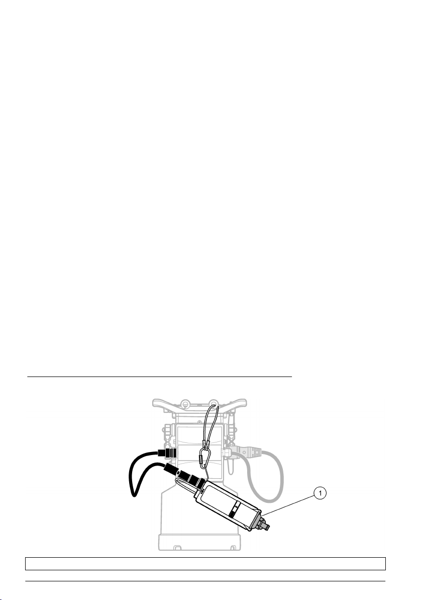
Product overview
The submerged area velocity (AV) sensor is used with Sigma flow meters, FL series flow loggers and
AS950 samplers to measure the flow rate in open channels. Refer to Figure 1.
The sensor is available in oil-filled and non-oil-filled versions. The non-oil sensor is used for
reasonably clear sites, or sites where the pipe may become dry. The oil-filled sensor is used for sites
with high levels of biological growth, grit or silt.
Note: Do not use an oil-filled sensor in a pipe that may become dry.
The submerged AV sensor connects to a FL series flow logger or AS950 sampler through an
AV9000 interface module. Refer to Replacement parts and accessories on page 19 to identify the
applicable AV9000 model for the flow logger or sampler.
Note: The submerged AV sensor connects directly to Sigma flow meters. An AV9000 interface module is not
necessary.
Figure 1 Submerged area velocity sensor
1 Junction box (optional) 6 Lanyard
2 Desiccant hub 7 Submerged AV sensor
3 Desiccant container 8 Carabiner clip
4 Air reference tube 9 Sensor cable
5 Connector
Theory of operation
The sensor operates as an area velocity sensor and follows the continuity equation.
Flow rate = wetted area x average velocity
6
English
Page 7

A pressure transducer in the sensor converts the pressure of the water to a level measurement. The
level measurement and the user-entered channel geometry are used to calculate the wetted area of
the flow stream.
The sensor also contains two ultrasonic transducers: one is a transmitter and the other is a receiver.
A 1 MHz signal is transmitted and reflected off of particles in the flow stream. The reflected signal is
received and its frequency is offset by the Doppler shift proportional to the velocity of the particles in
the flow stream. The flow logger converts the doppler shift in the returned ultrasound signals to a
velocity measurement.
Product components
Figure 2 shows the items in the shipment package. Contact the manufacturer if any components are
damaged or missing.
Figure 2 Product components
1 Submerged AV sensor 3 Junction box
2 Submerged AV sensor with junction box 4 Mounting screws (6x)
Installation
Installation guidelines
D A N G E R
Explosion Hazard. The non-IS AV sensors (770xx-xxx P/Ns) are not rated for use in classified Hazardous
Locations. For classified Hazardous Locations, use IS AV sensors (880xx-xxx PNs) installed per the control
drawings in 911/940 IS Blind Flow Meter manuals.
Potential confined space hazards. Only qualified personnel should conduct the tasks described in this section of
the manual.
• Do not install more than one sensor in pipes with a diameter of less than 61 cm (24 inches).
Multiple sensors in smaller pipes can create turbulent or accelerated flows near the sensors, which
may cause inaccurate measurements.
• Mount the sensor as close as possible to the bottom of the pipe invert. This will give the most
accurate low-velocity-level measurements.
• Do not monitor flows in the manhole invert. The best location for the sensor is 3 to 5 times the
sewer diameter/height upstream of the invert.
• Put monitoring sites as far from inflow junctions as possible to avoid interference caused by
combined flows.
D A N G E R
English
7
Page 8

• Objects such as rocks, pipe joints, or valve stems create turbulence and generate high-speed
flows near the object. Make sure the area 2 to 4 pipe diameters in front of the sensor installation is
clear of obstructions. Best accuracy is obtained when there are no flow disruptions within 5 to
10 pipe diameters.
• Do not use sites with low-velocity flows that create silt buildup in the invert or channel. Buildup of
silt near the sensor can inhibit the Doppler signal and cause inaccurate sensor readings and depth
measurements.
• Do not use sites with deep rapid flows where sensor installation would be difficult or dangerous.
• Do not use sites with high-velocity, low-depth flows. Splash-over and excessive turbulence around
the sensor can cause inaccurate data.
Interference
The AV9000 interface module includes a sensitive radio-frequency receiver capable of the detecting
very small signals. When connected to a flow logger or sampler communications or auxiliary power
ports, some line-powered equipment can add electrical noise that interferes with Doppler velocity
measurements. Interference with measurements is uncommon in typical sites.
The AV9000 is most sensitive to noise falling within its Doppler analysis span of 1 MHz ± 13.3 kHz.
Noise at other frequencies typically does not cause interference.
Some laptop computers can cause interference problems when operated from external AC power
adapters. If such a device has an effect on the measurements, operate the laptop computer with
batteries or disconnect the cable between the laptop computer and the flow logger or sampler.
Install the AV9000 interface module
The submerged AV sensor connects to a FL series flow logger or AS950 sampler through an
AV9000 interface module. Refer to Replacement parts and accessories on page 19 to identify the
applicable AV9000 interface module for the flow logger or sampler.
Note: The submerged AV sensor connects directly to Sigma flow meters. An AV9000 interface module is not
necessary.
1. Install the AV9000 interface module. Refer to the AV9000 documentation for instructions.
2. Connect the sensor cable to the AV9000 interface module. Refer to the AV9000 documentation
for instructions.
3. Connect the AV9000 cable to a sensor port (or terminal) on the flow logger or sampler. Refer to
the flow logger or sampler documentation for instructions.
Attach the desiccant hub
Attach the desiccant hub to the flow logger or sampler to give strain relief to the sensor cable and the
connector. Refer to Figure 3 to Figure 5.
For the best performance, make sure to install the desiccant container vertically with the end cap
pointed down. Refer to Figure 3 to Figure 5.
8
English
Page 9

Figure 3 Attach the desiccant hub—FL900 flow logger
1 End cap
Figure 4 Attach the desiccant hub—FL1500 flow logger
1 AV9000S with bare-wire connection 3 End cap
2 Accessories mounting plate
English 9
Page 10
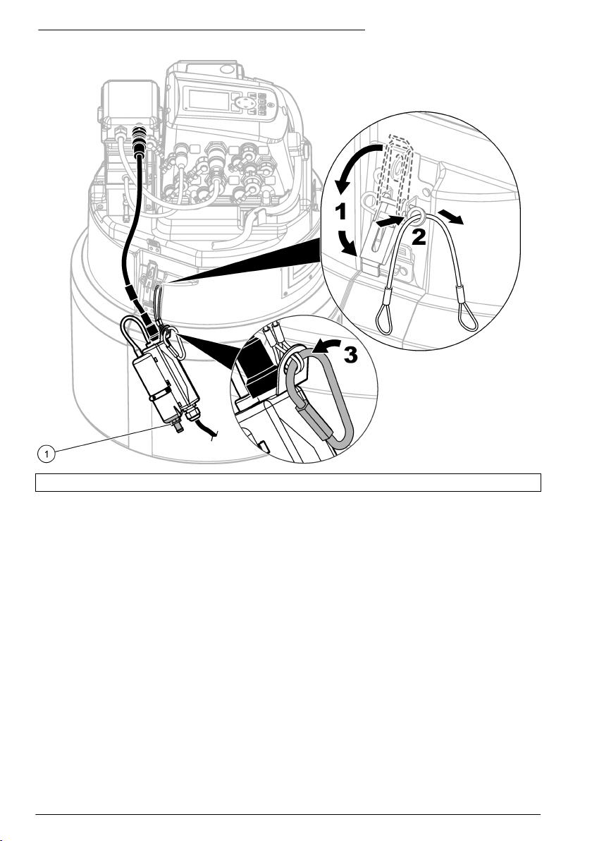
Figure 5 Attach the desiccant hub—AS950 portable sampler
1 End cap
Zero level calibration
If one or more of the statements that follow are correct, do a zero level calibration before the sensor
is installed.
• The installation location is a dry channel.
• It is not possible to get an accurate level in the flow because the level changes too rapidly.
• It is not possible to get an accurate level in the flow because of physical hazards.
Note: The sensor is factory-calibrated for the specified range and temperature.
Zero level calibration (FL series flow logger or sampler)
To do a zero level calibration with an FL900 flow logger, do a zero level calibration (zero calibration
in air) with the FSDATA Desktop Setup Wizard. Refer to the FSDATA Desktop documentation for
instructions. As an alternative, do a manual zero level calibration (zero calibration in air) with
FSDATA Desktop.
To do a zero level calibration with the FL1500 flow logger or sampler, refer to the FL1500 flow logger
or sampler documentation for instructions. As an alternative, do a zero level calibration with the
FSDATA Desktop Setup Wizard when the sensor is connected to an FL1500 flow logger.
Make sure that the sensor is out of the water and on a flat, level, horizontal surface.
Note: If the sensor is replaced, removed for maintenance or moved to another instrument, do a zero level
calibration.
10
English
Page 11

Zero level calibration (Sigma 910 to 950 flow meters)
Do a zero level calibration as follows:
Note: If the sensor is replaced, removed for maintenance or moved to another instrument, do a zero level
calibration again.
1. Connect the flow meter to a computer with InSight software. Refer to the flow meter
documentation for instructions.
2. Start the InSight software on the computer.
3. Select Remote Programming.
4. From the Real Time Operations list, select the level sensor.
5. Remove the probe from the liquid and place the sensor flat on the tabletop or floor with the
sensor (the plate with holes) face down.
6. Push OK on the dialog box when complete.
Attach the sensor to the mounting band
Mounting bands have pre-drilled holes for direct mounting of the sensor to the band. Refer to the
steps and the figures to mount the sensor on the mounting band.
Note: If the sensor is the oil-filled type, make sure the sensor is filled with oil before mounting the sensor to the
mounting band. Refer to the Fill sensor oil section of this manual.
1. Attach the sensor to the spring ring (Figure 6). Mount the sensor so that the pressure transducer
extends past the edge of the ring.
2. Route the cable along the edge of the band (Figure 6).
3. Use nylon-wire ties to fasten the cable to the mounting band.
The cable should exit the tied area at or near the top of the pipe.
Note: If a large amount of silt exists in the bottom of the pipe, rotate the band until the sensor is out of the silt
(Figure 8 on page 14). Make sure the sensor remains below the minimum expected water level at all times.
Silt must be measured frequently but not disturbed.
English
11
Page 12

Figure 6 Attach the sensor to the mounting band
1 Sensor 3 Sensor cable
2 Spring ring 4 Screws (2)
Place the sensor and mounting band in the pipe
1. Position the sensor in the flow. Figure 7 shows a standard upstream configuration, a standard
downstream configuration and a downstream sensor-reversed configuration.
To help determine the best configuration for the site, refer to Table 1. For more information on
configurations, refer to the appropriate logger manual.
2. Slide the mounting band inside the pipe as far as possible to prevent drawdown effects near the
end of the pipe.
3. Place the sensor at the bottom-most point in the channel. If excessive silt is present on the
bottom of the pipe, rotate the band in the pipe until the sensor is out of the silt. Refer to Figure 8.
12
English
Page 13
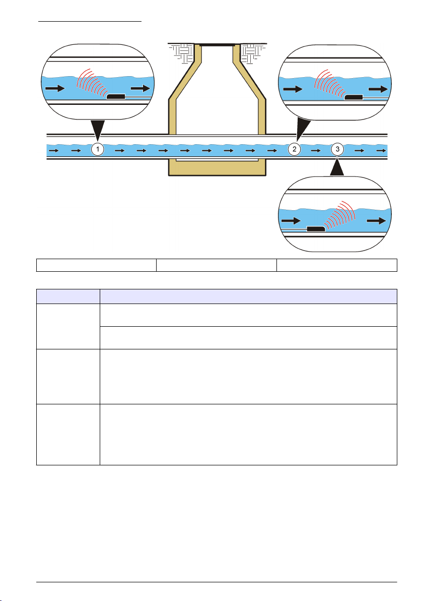
Figure 7 Sensor positions
1 Upstream, facing flow 2 Downstream, facing flow 3 Downstream, reversed
Table 1 Selecting probe direction
Option Description
Upstream Recommended for most applications. The flow stream over the sensor should be as straight
Downstream Use this option when the sensor is installed downstream of the measurement point (where
Downstream
(reversed sensor)
as possible with no drops or turns near the measurement point.
Mount the sensor in the pipe with the beveled edge pointed toward the flow where the flow
stream enters the measurement area.
the flow stream exits the site). This option is useful when more than one flow stream enters a
site and the combined flow of all streams is measured at a single exit point. This option can
also be used if there are hydraulics preventing the sensor from being mounted in upstream
area.
Mount the sensor facing the flow.
Use this option when Option B will not work due to poor flow uniformity in the vault. The
maximum velocity read in this kind of installation is 5 fps when the AV9000 interface module
is not used. Mount the sensor in the downstream direction. The manufacturer recommends
verifying the velocity by profiling flow and using a velocity site multiplier, if required, for more
accurate reading.
Note: When the AV9000 interface module and submerged AV sensor are used with the FL900 logger, the
user has the option to select Reversed Sensor on the Sensor Port Set Up menu.
English 13
Page 14

Figure 8 Avoiding silt when mounting the sensor
1 Water 3 Sensor
2 Pipe 4 Silt
Operation
For sensors connected to an FL900 flow logger, connect a computer with FSDATA Desktop software
to the flow logger to configure, calibrate and collect data from the sensors. Refer to the FSDATA
Desktop documentation to configure, calibrate and collect data from the sensor.
For sensors connected to an FL1500 flow logger, refer to the FL1500 flow logger documentation to
configure, calibrate and collect data from the sensors. As an alternative, connect a computer with
FSDATA Desktop software to the flow logger to configure, calibrate and collect data from the
sensors. Refer to the FSDATA Desktop documentation to configure, calibrate and collect data from
the sensor.
For sensors connected to an AS950 sampler, refer to the AS950 sampler documentation to
configure, calibrate and collect data from the sensors.
For sensors connected to a Sigma 910, 911, 920, 930 or 940 flow meter, connect a computer with
InSight software to the Sigma flow meter to configure, calibrate and collect data from the sensors.
Install the software
Make sure that the latest version of the FSDATA Desktop software or InSight software is installed on
the computer as applicable. Download the software from http://www.hachflow.com. Click Support,
then select Software Downloads.
Configure the sensor
For sensors connected to an FL900 flow logger, configure the sensors with the FSDATA Desktop
Setup Wizard. Refer to the FSDATA Desktop documentation for instructions.
14
English
Page 15

For sensors connected to an FL1500 flow logger or AS950 sampler, refer to the FL1500 flow logger
or sampler documentation to configure the sensors. As an alternative, configure the sensors with the
FSDATA Desktop Setup Wizard when the sensors are connected to an FL1500 flow logger.
For sensors connected to a Sigma flow meter, do the steps in Level calibration for Sigma flow meters
on page 15.
Note: If a sensor is replaced, removed for maintenance or moved to another instrument, do a level calibration.
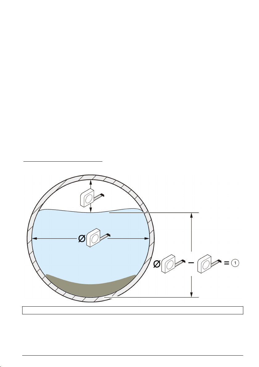
Level calibration for Sigma flow meters
1. With the sensor installed in the flow, monitor the Current Status with a PC using Insight software
or a flow meter display.
2. Physically measure the distance from the top of the pipe to the surface of the water. Refer to
Figure 9.
3. Subtract the number from step 2 from the pipe diameter. Refer to Figure 9.
The result is the water depth. Refer to Figure 9.
4. Use the Adjust Level function of the software to enter the physically-measured water depth.
Figure 9 Measure the water level
1 Water level
Maintenance
C A U T I O N
Multiple hazards. Only qualified personnel must conduct the tasks described in this section of the
document.
Clean the sensor
Clean the transducer port when:
• Unexpected increases or decreases in flow or level trends occur
• Level data are missing or incorrect but velocity data are valid
English
15
Page 16

• Excessive silt deposits have built up between the transducer and the protective cover
Notes
• Do not touch the sensor transducer as this will cause damage and incorrect sensor operation.
• Use only approved cleaning solutions as listed in Table 2. Do not use any type of brush or rag to
clean the pressure transducer as this will cause damage and incorrect sensor operation. If there
are debris, spray the membrane with water and use a Q-tip to carefully remove the buildup.
• If the gasket is missing or damaged, install a new one. A damaged or missing gasket will cause
inaccurate readings.
• After cleaning the sensor, clean the gasket and protective cover before they are installed.
• After cleaning an oil-filled sensor, replenish the sensor oil.
• If a sensor must be taken out of service for an extended period, do not store the sensor on a dry
shelf. The manufacturer recommends that the sensor be stored with the sensor head in a bucket
of water to keep the oil debris from crusting in the pressure transducer canal.
To clean the sensor:
1. Soak the sensor in soapy water.
2. Remove the screws from the protective cover. Refer to Figure 10.
3. Remove the cover and gasket. Refer to Figure 10.
4. Carefully swirl the sensor in an appropriate cleaning solution to remove soil. Use a spray or
squeeze bottle to wash away heavier deposits.
5. Clean the gasket and cover.
6. Attach the gasket and cover. tighten the screws until the gasket starts to compress.
Figure 10 Sensor protective cover and gasket
1 Protective cover 2 Gasket 3 Sensor
16 English
Page 17

Table 2 Acceptable and unacceptable cleaning solutions
Acceptable Do not use
Dish detergent and water Concentrated bleach
Window cleaner Kerosene
Isopropyl alcohol Gasoline
Dilute acids Aromatic hydrocarbons
Replace the desiccant
N O T I C E
Do not operate the sensor without desiccant beads or with green desiccant beads. Permanent damage to the
sensor can occur.
Immediately replace the desiccant when it changes to green. Refer to Figure 11.
Note: It is not necessary to remove the desiccant container from the desiccant hub to install new desiccant.
At step 5 of Figure 11, make sure that the O-ring is clean and has no dirt or debris. Examine the Oring for cracking, pits or sign of damage. Replace the O-ring if it has damage. Apply grease to dry or
new O-rings to make installation easier, to get a better seal and to increase the life of the O-ring.
For the best performance, make sure to install the desiccant container vertically with the end cap
pointed down. Refer to Attach the desiccant hub on page 8.
Note: When the beads just begin to turn green, it may be possible to rejuvenate them by heating. Remove the
beads from the canister and heat them at 100-180 ºC (212-350 ºF) until they turn orange. Do not heat the canister.
If the beads do not turn orange, they must be replaced with new desiccant.
Figure 11 Replace the desiccant
English 17
Page 18

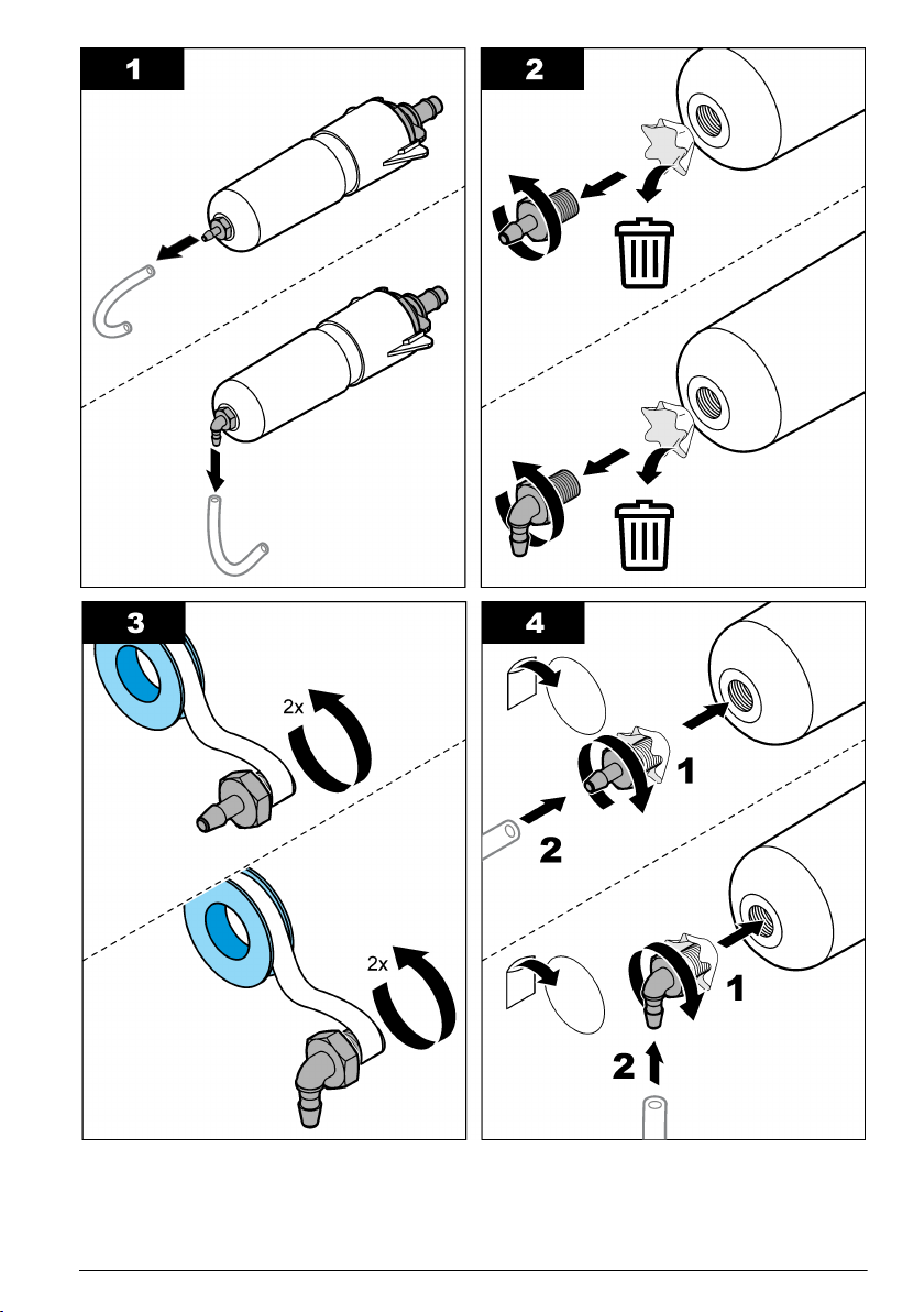
Replace the hydrophobic membrane
Replace the hydrophobic membrane when:
• Unexpected increases or decreases in level trends occur.
• Level data is missing or incorrect, but the velocity data is valid.
• The membrane is torn or has become saturated with water or grease.
Refer to the illustrated steps that follow to replace the membrane. At step 4, make sure that the
following occurs:
• The smooth side of the hydrophobic membrane is against the inner surface of the desiccant
container.
• The hydrophobic membrane bends up and goes fully into the thread until it is not seen.
• The hydrophobic membrane turns with the nipple when the nipple in the desiccant container turns.
If the membrane does not turn, it has damage. Start the procedure again with a new membrane.
For the best performance, make sure to install the desiccant container vertically with the end cap
pointed down. Refer to Attach the desiccant hub on page 8.
18 English
Page 19

Replenish the sensor oil
Inspect the oil in the sensor for large air bubbles during customer-scheduled service duty cycles.
Large bubbles can reduce the anti-fouling properties of the oil. Small bubbles (< ¼-in. diameter) do
not affect the oil properties.
To replenish the sensor oil, refer to the documentation supplied with the silicone oil refill kit. Refer to
Replacement parts and accessories on page 19 for ordering information.
Replacement parts and accessories
W A R N I N G
Personal injury hazard. Use of non-approved parts may cause personal injury, damage to the
instrument or equipment malfunction. The replacement parts in this section are approved by the
manufacturer.
Note: Product and Article numbers may vary for some selling regions. Contact the appropriate distributor or refer to
the company website for contact information.
Replacement parts
Description Item number
Desiccant beads, bulk, 1.5 pound canister 8755500
Desiccant container 8542000
Hydrophobic membrane 3390
O-ring, dessicant container end cap, 1.176 ID x 0.070 OD 5252
Silicon oil, includes two 50-mL oil packs to refill 100 sensors 7724700
English 19
Page 20

Description Item number
Silicon oil refill kit, includes:
7724800
dispensing tool, two 50-mL oil pack, instruction sheet and miscellaneous hardware
Desiccant hub
1
7722800
Accessories
Description Item number
AV9000 interface module, FL900 flow loggers 8531300
AV9000S interface module with bare-wire connection, FL1500 flow loggers 9504601
AV9000S interface module, AS950 portable samplers 9504600
Accessories mounting plate, FL1500 flow loggers 8309300
Custom cable, sensor to junction box, 0.3 to 30 m (1 to 99 ft) 77155-PRB
Custom cable, junction box to desiccant hub, 0.3 to 30 m (1 to 99 ft) 77155-HUB
Silicone potting gel kit for junction box 7725600
Gel fill, silicone potting
Gel fill, dispenser gun
Retrofit kit, change a sensor with a non-oil cover plate to a sensor with an oil-filled cover plate,
includes 7724800
Insertion tool, street-level installation of mounting rings 9574
Mounting ring for ∅ 15.24 cm (6 in.) pipe
Mounting ring for ∅ 20.32 cm (8 in.) pipe
Mounting ring for ∅ 25.40 cm (10 in.) pipe
Mounting ring for ∅ 30.48 cm (12 in.) pipe
Mounting ring for ∅ 38.10 cm (15 in.) pipe
Mounting ring for ∅ 45.72 cm (18 in.) pipe
Mounting ring for ∅ 50.8 to 53.34 cm (20 to 21 in.) pipe
Mounting ring for ∅ 61 cm (24 in.) pipe
2
3
7729800
7715300
7730000
4
4
4
5
5
5
5
5
1361
1362
1363
1364
1365
1366
1353
1370
Mounting band selection chart
Pipe diameter Mounting Band Selection
Item number
1473--6.25"
(15.85 cm) long,
adds 2" (5.08 cm) to
band diameter
1
Use part number 77155-HUB to select the cable length after the desiccant hub.
2
Order three to fill one junction box.
3
Can also be used as a silicone oil fill gun
4
Requires item number 3263
5
The sensor attaches directly to band.
6
In addition to the band segments shown below, a complete mounting band assembly requires
Item number
1525--9.5"
(24.13 cm) long,
adds 3" (7.62 cm) to
band diameter
Item number
1759--19" (48.26 cm)
long, adds 6"
(15.24 cm) to band
diameter
one AV Sensor Mounting Clip (3263) and one Scissors Jack Assembly (3719).
20 English
6
Item number
1318--50.25" (127 cm)
long, adds 16"
(40.64 cm) to band
diameter
Page 21

8" (20.32 cm) 0 0 1 0
10" (25.4 cm) 1 0 1 0
12" (30.48 cm) 0 1 1 0
15" (38.1 cm) 0 2 1 0
18" (45.72 cm) 0 1 2 0
21" (53.34 cm) 0 2 2 0
24" (60.96 cm) 0 1 3 0
27" (68.58 cm) 1 0 1 1
30" (76.2 cm) 1 1 1 1
33" (83.2 cm) 1 0 2 1
36" (91.44 cm) 1 1 2 1
42" (1.06 m) 1 1 3 1
45" (1.14 m) 1 1 1 2
48" (1.21 m) 1 0 2 2
English 21
Page 22

Table des matières
Caractéristiques à la page 22 Fonctionnement à la page 34
Généralités à la page 23 Maintenance à la page 36
Installation à la page 27 Pièces de rechange et accessoires à la page 40
Caractéristiques
Les caractéristiques techniques peuvent être modifiées sans préavis.
Caractéristiques - Capteur de vitesse en surface immergé
Les performances varient selon la taille du canal, la forme du canal et les conditions du site.
Mesure de la vitesse
Méthode Doppler ultrasonique
Transducer_type: Cristaux jumeaux piézoélectriques de 1 MHz
Profondeur minimale type pour la
vitesse
Plage de mesures de -1,52 à 6,10 m/s (de -5 à 20 pi/s)
Précision ± 2 % de la mesure (dans l'eau avec un profil de vitesse uniforme)
Mesure du niveau
Méthode Transducteur de pression avec diaphragme en acier inoxydable
Précision (statique)
2 cm (0,8 po.)
• ± 0,16 % pleine échelle ± 1,5 % de la mesure à température
constante (± 2,5 °C)
• ± 0,20 % pleine échelle ± 1,75 % de la mesure entre 0 et 30 °C (32 à
86 °F)
• ± 0,25 % pleine échelle ± 2,1 % de la mesure entre 0 et 70 °C (32 à
158 °F)
Erreur de profondeur induite par la
vitesse
Plage de niveau
Niveau autorisé
Caractéristiques générales
Admission d'air Référence à la pression atmosphérique protégée contre l'humidité
Température de fonctionnement 0 à 70 °C (32 à 158 °F)
Plage de température compensée
selon le niveau
Matériaux Coque extérieure en Noryl® avec remplissage époxy à l'intérieur
Consommation électrique Inférieure ou égale à 1,2 W à 12 VCC
Câble Câble du capteur en uréthane avec aération
Connecteur Anodisation dure, conforme aux spécifications militaires 5015
Compensée selon la vitesse de l'écoulement
• Standard : 0–3 m (0–10 pieds)
• Etendue : 0–9 m (0–30 pieds)
• Standard : 10,5 m (34,5 pieds)
• Etendu : 31,5 m (103,5 pieds)
0 à 70 °C (32 à 158 °F)
22 Français
Page 23

Longueurs de câble disponibles
Diamètre du câble 0,91 cm (0,36 po.)
Dimensions 2,3 x 3,8 x 13,5 cm (0,9 x 1,5 x 5,31 po.) (H x l x L)
Instruments compatibles Echantillonneurs Sigma 910, 920, 930, 930 T, 950, 900 Max et modules
• Standard : 9, 15, 23 et 30,5 m (30, 50, 75, 100 pieds)
• Sur mesure : 30,75 m (101 pieds) à 76 m (250 pieds) maximum
d'interface AV9000 pour enregistreurs de débit de la série FL et
échantillonneurs AS950
Caractéristiques - Module d'interface AV9000
Mesure de la vitesse
Méthode de mesure 1 MHz ultrasons Doppler
Type d'analyse Doppler Analyse spectrale numérique
de -1,52 à 6,10 m/s (de -5 à 20 pi/s)
± 2 % de la mesure ou 0,05 pi/s (profil de vitesse uniforme, salinité connue,
écoulement positif. Les performances réelles sont spécifiques au site.)
Précision Doppler ± 1 % de la mesure ou 0,025 pi/s (avec signal Doppler simulé
Alimentation requise
Tension d'alimentation 9-15 VCC
Courant maximum < 130 mA à 12 VCC avec capteur de vitesse en surface immergé
Energie par mesure < 15 joules (caractéristique)
Température de fonctionnement
-18 à 60 °C (0 à 140 °F) à 95 % HR
Boîtier
Dimensions (L x H x P) AV9000 : 13 x 17,5 x 5 cm
Classement environnemental NEMA 6P, IP 68
Matériau du boîtier PC/ABS
électroniquement, vitesse équivalente à -25 à +25 pi/s). Reportez-vous à
Configuration du capteur à la page 35.
AV9000S : 12,01 x 14,27 x 6,86 cm
Généralités
En aucun cas le constructeur ne saurait être responsable des dommages directs, indirects, spéciaux,
accessoires ou consécutifs résultant d'un défaut ou d'une omission dans ce manuel. Le constructeur
se réserve le droit d'apporter des modifications à ce manuel et aux produits décrits à tout moment,
sans avertissement ni obligation. Les éditions révisées se trouvent sur le site Internet du fabricant.
Consignes de sécurité
A V I S
Le fabricant décline toute responsabilité quant aux dégâts liés à une application ou un usage inappropriés de ce
produit, y compris, sans toutefois s'y limiter, des dommages directs ou indirects, ainsi que des dommages
consécutifs, et rejette toute responsabilité quant à ces dommages dans la mesure où la loi applicable le permet.
L'utilisateur est seul responsable de la vérification des risques d'application critiques et de la mise en place de
mécanismes de protection des processus en cas de défaillance de l'équipement.
Français 23
Page 24

Veuillez lire l'ensemble du manuel avant le déballage, la configuration ou la mise en fonctionnement
de cet appareil. Respectez toutes les déclarations de prudence et d'attention. Le non-respect de
cette procédure peut conduire à des blessures graves de l'opérateur ou à des dégâts sur le matériel.
Assurez-vous que la protection fournie avec cet appareil n'est pas défaillante. N'utilisez ni n'installez
cet appareil d'une façon différente de celle décrite dans ce manuel.
Interprétation des indications de risques
D A N G E R
Indique une situation de danger potentiel ou imminent qui, si elle n'est pas évitée, entraîne des blessures graves,
voire mortelles.
A V E R T I S S E M E N T
Indique une situation de danger potentiel ou imminent qui, si elle n'est pas évitée, peut entraîner des blessures
graves, voire mortelles.
Indique une situation de danger potentiel qui peut entraîner des blessures mineures ou légères.
Indique une situation qui, si elle n'est pas évitée, peut occasionner l'endommagement du matériel. Informations
nécessitant une attention particulière.
A T T E N T I O N
A V I S
Etiquettes de mise en garde
Lisez toutes les informations et toutes les étiquettes apposées sur l’appareil. Des personnes peuvent
se blesser et le matériel peut être endommagé si ces instructions ne sont pas respectées. Un
symbole sur l'appareil est référencé dans le manuel et accompagné d'une déclaration de mise en
garde.
Ceci est le symbole d'alerte de sécurité. Se conformer à tous les messages de sécurité qui suivent ce
symbole afin d'éviter tout risque de blessure. S'ils sont apposés sur l'appareil, se référer au manuel
d'utilisation pour connaître le fonctionnement ou les informations de sécurité.
Ce symbole indique la présence d'appareils sensibles aux décharges électrostatiques et indique que
des précautions doivent être prises afin d'éviter d'endommager l'équipement.
Le matériel électrique portant ce symbole ne doit pas être mis au rebut dans les réseaux domestiques
ou publics européens. Retournez le matériel usé ou en fin de vie au fabricant pour une mise au rebut
sans frais pour l'utilisateur.
Précautions concernant l'espace confiné
D A N G E R
Risque d’explosion Une formation portant sur les tests de pré-entrée, la ventilation, les procédures
d'entrée, les procédures d'évacuation/de sauvetage et les mesures de sécurité est nécessaire avant
d'entrer dans des lieux confinés.
Les informations suivantes sont fournies dans le but d'aider les utilisateurs à appréhender les
dangers et les risques associés aux espaces confinés.
Le 15 avril 1993, le règlement final de l'OSHA concernant le CFR 1910.146, Permit Required
Confined Spaces (Espaces confinés nécessitant l'autorisation), est devenue une loi. Cette norme
affecte directement plus de 250 000 sites industriels aux Etats-Unis et a été rédigée dans le but de
protéger la santé et la sécurité des travailleurs en espace confiné.
Définition d'un espace confiné :
24
Français
Page 25

Tout endroit ou clôture qui présente (ou est susceptible de présenter) une ou plusieurs des
conditions suivantes :
• Une atmosphère qui contient une concentration d'oxygène inférieure à 19,5 % ou supérieure à
23,5 % et/ou une concentration de sulfure d'hydrogène (H2S) supérieure à 10 ppm.
• Une atmosphère qui peut être inflammable ou explosive en présence de gaz, vapeurs, brumes,
poussières ou fibres.
• Des matériaux toxiques qui, en cas de contact ou d'inhalation, sont susceptibles d'occasionner
des blessures, des problèmes de santé ou la mort.
Les espaces confinés ne sont pas conçus pour l'occupation humaine. Les espaces confinés
disposent d’un accès limité et présentent des risques connus ou potentiels. Les trous d’homme, les
colonnes, les tuyaux, les cuves, les chambres de commutation et autres emplacements similaires
sont des exemples d’espaces confinés.
Il convient de toujours suivre les procédures de sécurité standard avant d'entrer dans des espaces
et/ou des endroits confinés soumis à des gaz dangereux, des vapeurs, des brumes, des poussières
ou des fibres Avant de pénétrer dans un espace confiné, veuillez lire l'ensemble des procédures
liées à l'accès.
Présentation du produit
Le capteur de vitesse en surface (AV) immergé est utilisé avec les débitmètres Sigma, les
enregistreurs de débit de la série FL et les échantillonneurs AS950, en vue de mesurer le débit dans
des canaux ouverts. Reportez-vous à Figure 1.
Le capteur est disponible en version avec et sans huile. Le capteur sans huile est destiné aux sites
raisonnablement propres ou aux sites où les tuyaux peuvent s'assécher. Le capteur à huile est
destiné aux sites très exposés à la prolifération biologique, au sable ou à la boue.
Remarque : N'utilisez pas de capteur à huile dans un tuyau susceptible de s'assécher.
Le capteur AV immergé se connecte à un enregistreur de débit de la série FL ou à un
échantillonneur AS950 via un module d'interface AV9000. Pour identifier le modèle
AV9000 concerné pour l'enregistreur de débit ou l'échantillonneur, consultez la section Pièces de
rechange et accessoires à la page 40.
Remarque : Le capteur AV immergé se connecte directement aux débitmètres Sigma. Aucun module d'interface
AV9000 n'est nécessaire.
Français
25
Page 26
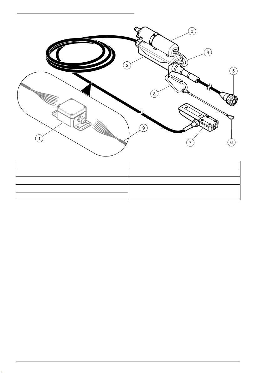
Figure 1 Capteur de vitesse en surface immergé
1 Bornier de raccordement (en option) 6 Cordon
2 Boîtier dessiccant 7 Capteur AV immergé
3 Conteneur de dessiccant 8 Mousqueton
4 Tube de référence de l'air 9 Câble du capteur
5 Connecteur
Principe de fonctionnement
Le capteur fonctionne comme un capteur de vitesse en surface et suit l'équation de continuité.
Débit = surface mouillée x vitesse moyenne
Un transducteur de pression à l'intérieur du capteur convertit la pression de l'eau en mesure de
niveau. La mesure de niveau et la géométrie du canal configurée par l'utilisateur servent à calculer la
zone immergée par l'écoulement.
Le capteur contient également deux transducteurs ultrasoniques : un émetteur et un récepteur. Un
signal de 1 MHz transmis se réfléchit sur les particules présentes dans le flux d'eau. Le signal
réfléchi est reçu et sa fréquence est compensée par l'effet Doppler proportionnel à la vitesse des
particules au niveau du flux. L'enregistreur d'écoulement convertit l'effet Doppler dans les signaux
ultrasons renvoyés en mesure de la vitesse.
Composants du produit
Figure 2 illustre les éléments du contenu de la livraison. Contactez le fabricant si l'un des
composants est endommagé ou manquant.
26
Français
Page 27
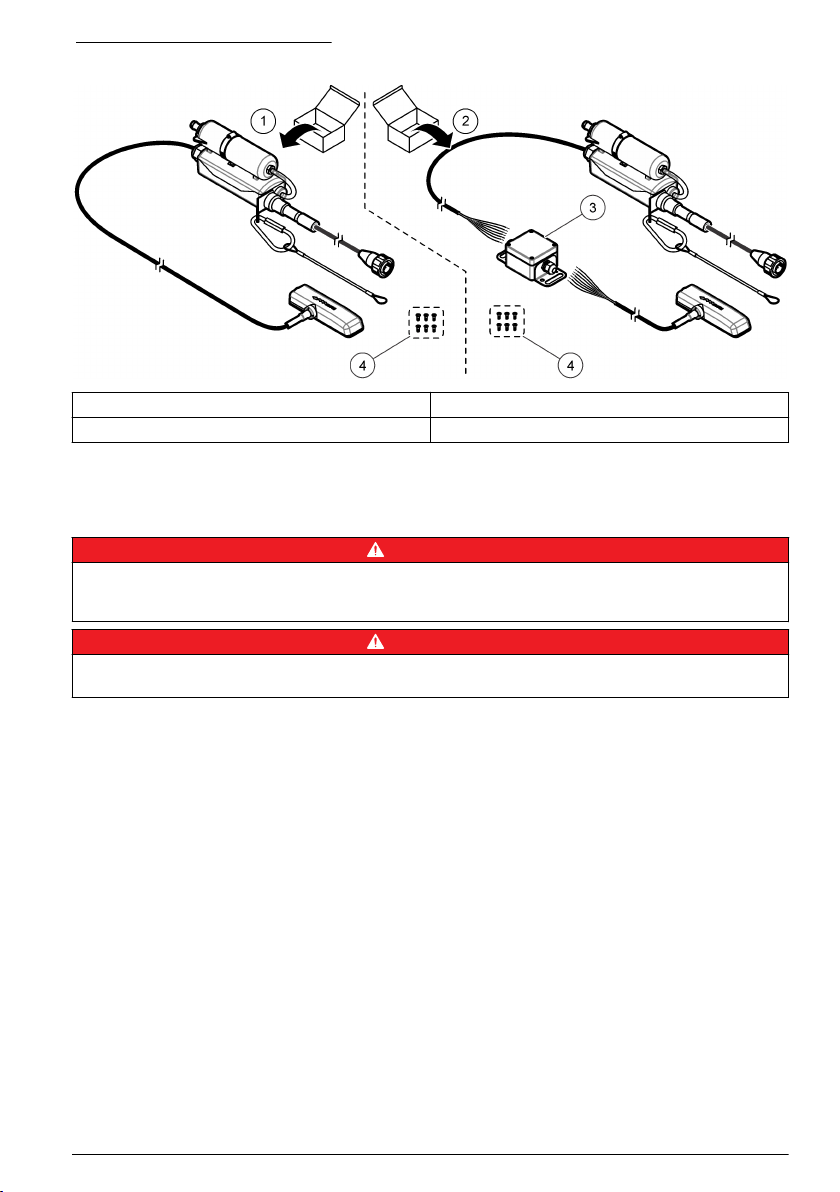
Figure 2 Composants du produit
1 Capteur AV immergé 3 Boîte de jonction
2 Capteur AV immergé avec boîte de jonction 4 Vis de fixation (6)
Installation
Directives d'installation
D A N G E R
Risque d'explosion Les capteurs H/V non IS (réf. 770xx-xxx) ne sont pas conçus pour les zones classées
dangereuses. Pour les zones classées dangereuses, utilisez des capteurs H/V IS (réf. 880xx-xxx) et installez-les
conformément aux schémas de contrôle du manuel du débitmètre 911/940 IS.
D A N G E R
Dangers potentiels dans les espaces confinés. Seul le personnel qualifié est autorisé à entreprendre les
opérations décrites dans cette section du manuel.
• N'installez pas plus d'un capteur dans les tuyaux d'un diamètre inférieur à 61 cm (24 pouces).
Plusieurs capteurs dans un petit tuyau peuvent créer des turbulences ou des accélérations à
proximité des capteurs, entraînant des mesures erronées.
• Montez le capteur le plus près possible du bas du radier du tuyau. Vous obtiendrez ainsi des
mesures très précises du niveau à faible vitesse.
• Ne surveillez pas les écoulements dans le radier de la trappe d'accès. Il est recommandé
d'installer le capteur à une distance égale à 3 voire 5 fois le diamètre/hauteur de l'égout en amont
du radier.
• Placez les sites de surveillance le plus loin possible des jonctions entrantes pour éviter les
interférences causées par la combinaison d'écoulements.
• Les objets tels que les cailloux, les joints des tuyaux ou les tiges de soupape créent des
turbulences et génèrent des écoulements haut débit à proximité de l'objet. Vérifiez que la zone
équivalente à 2 voire 4 fois le diamètre du tuyau devant le capteur ne présente aucune
obstruction. On obtient les meilleures mesures lorsque l'écoulement est ininterrompu sur une
distance équivalente à 5 voire 10 fois le diamètre du tuyau.
• N'utilisez pas les sites à faibles écoulements qui génèrent des dépôts de boue au niveau du radier
ou du canal. Le dépôt de boue à côté du capteur peut empêcher le signal Doppler et entraîner des
mesures erronées au niveau du capteur et de la profondeur.
• N'utilisez pas les sites à écoulements profonds et rapides où l'installation d'un capteur serait
complexe voire dangereuse.
• N'utilisez pas les sites à écoulements rapides et faible profondeur. Les projections et les
turbulences autour du capteur peuvent entraîner des données erronées.
Français
27
Page 28
Interférence
Le module d'interface AV9000 comprend un récepteur radiofréquence sensible, capable de détecter
des signaux très faibles. Lorsqu'il est connecté à des communications d'enregistreur de débit ou
d'échantillonneur, ou à des ports d'alimentation auxiliaires, certains équipements alimentés peuvent
générer un bruit électrique qui interfère avec des mesures de vitesse Doppler. Les interférences
avec les mesures sont rares sur les sites classiques.
Le modèle AV9000 est plus sensible aux interférences dans sa plage d'analyse Doppler de 1 MHz
± 13,3 kHz. A d'autres fréquences, le bruit ne provoque généralement aucune interférence.
Certains ordinateurs portables fonctionnant sur des adaptateurs secteur externes peuvent causer
des problèmes d'interférences. Si un tel dispositif affecte les mesures, faites fonctionner l'ordinateur
portable sur batterie ou débranchez le câble entre l'ordinateur portable et l'enregistreur de débit ou
l'échantillonneur.
Installation du module d'interface AV9000
Le capteur AV immergé se connecte à un enregistreur de débit de la série FL ou à un
échantillonneur AS950 via un module d'interface AV9000. Pour identifier le module d'interface
AV9000 correspondant à l'enregistreur de débit ou à l'échantillonneur, consultez la section Pièces de
rechange et accessoires à la page 40.
Remarque : Le capteur AV immergé se connecte directement aux débitmètres Sigma. Aucun module d'interface
AV9000 n'est nécessaire.
1. Installez le module d'interface AV9000. Pour obtenir des instructions, reportez-vous à la
documentation AV9000.
2. Connectez le câble du capteur au module d'interface AV9000. Pour obtenir des instructions,
reportez-vous à la documentation AV9000.
3. Connectez le câble AV9000 à un port (ou terminal) de capteur de l'enregistreur de débit ou de
l'échantillonneur. Pour obtenir des instructions, reportez-vous à la documentation de
l'enregistreur de débit ou de l'échantillonneur.
Fixation du boîtier dessiccant
Fixez le boîtier dessiccant à l'enregistreur de débit ou à l'échantillonneur afin de dissiper la tension
du câble du capteur et du connecteur. Reportez-vous aux sections Figure 3 à Figure 5.
Pour des performances optimales, veillez à installer le conteneur de dessiccant à la verticale,
bouchon d'extrémité dirigé vers le bas. Reportez-vous aux sections Figure 3 à Figure 5.
Figure 3 Fixation du boîtier dessiccant - Enregistreur de débit FL900
1 Bouchon d'extrémité
28 Français
Page 29

Figure 4 Fixation du boîtier dessiccant - Enregistreur de débit FL1500
1 AV9000S avec raccordement des fils dénudés 3 Bouchon d'extrémité
2 Plaque de montage des accessoires
Français 29
Page 30

Figure 5 Fixation du boîtier dessiccant - Echantillonneur portable AS950
1 Bouchon d'extrémité
Calibration du niveau zéro
Si une ou plusieurs des affirmations suivantes sont correctes, procédez à une calibration du niveau
zéro avant d'installer le capteur.
• L'emplacement d'installation est un canal sec.
• Il n'est pas possible d'obtenir un niveau précis dans le flux parce que le niveau change trop
rapidement.
• Il n'est pas possible d'obtenir un niveau précis dans le flux en raison des risques physiques.
Remarque : Le capteur est calibré en usine pour la plage et la température spécifiées.
Calibration du niveau zéro (échantillonneur ou enregistreur de débit de la série FL)
Pour procéder à une calibration de niveau zéro avec un enregistreur de débit FL900, effectuez une
calibration de niveau zéro (calibration du zéro dans l'air) avec l'assistant de configuration FSDATA
Desktop. Pour obtenir des instructions, reportez-vous à la documentation du logiciel FSDATA
Desktop. Vous pouvez également réaliser une calibration de niveau zéro manuelle (calibration du
zéro dans l'air) avec le logiciel FSDATA Desktop.
Pour obtenir des instructions quant à la réalisation d'une calibration du niveau zéro avec
l'échantillonneur ou l'enregistreur de débit FL1500, reportez-vous à la documentation de
l'échantillonneur ou de l'enregistreur de débit FL1500. Vous pouvez également procéder à une
calibration de niveau zéro avec l'assistant de configuration FSDATA Desktop lorsque le capteur est
connecté à un enregistreur de débit FL1500.
30
Français
Page 31

Assurez-vous que le capteur est hors de l'eau et qu'il se trouve sur une surface plane et horizontale.
Remarque : Effectuez une calibration de niveau zéro si le capteur est remplacé, retiré à des fins d'entretien ou
déplacé vers un autre instrument.
Calibration du niveau zéro (débitmètres Sigma 910 à 950)
Effectuez une calibration de niveau zéro comme suit :
Remarque : Effectuez à nouveau une calibration de niveau zéro si le capteur est remplacé, retiré à des fins
d'entretien ou déplacé vers un autre instrument.
1. Branchez le débitmètre à un ordinateur exécutant le logiciel InSight. Reportez-vous à la
documentation du débitmètre pour obtenir des instructions.
2. Démarrez le logiciel InSight sur l'ordinateur.
3. Sélectionnez la programmation à distance.
4. Dans la liste Real Time Operations (Opérations en temps réel), sélectionnez le capteur de
niveau.
5. Retirez la sonde du liquide et placez le capteur à plat sur une table ou le sol, la face avec des
trous tournée vers le bas.
6. Appuyez sur OK dans la boîte de dialogue une fois terminé.
Fixation du capteur à la bande de montage
Les bandes de montage sont dotées de trous prépercés pour monter directement le capteur sur la
bande. Reportez-vous aux étapes et figures pour monter le capteur sur la bande de montage.
Remarque : S'il s'agit d'un capteur à huile, vérifiez que le capteur est rempli d'huile avant de le monter sur la
bande. Reportez-vous à la section Remplissage d'huile de ce manuel.
1. Fixez le capteur à la bande de montage (Figure 6). Montez le capteur de manière à ce que le
transducteur de pression dépasse du bord de la bande de montage.
2. Acheminez le câble le long du bord de la bande (Figure 6).
3. Utilisez des attaches en fil de nylon pour fixer le câble à la bande de montage.
Le câble ne doit plus être attaché au niveau ou à côté du haut du tuyau.
Remarque : S'il y a beaucoup de boue au bas du tuyau, tournez la bande jusqu'à ce que le capteur sorte de la
boue (Figure 8 à la page 34). Vérifiez que le capteur reste en permanence en dessous du niveau d'eau
minimum autorisé. Mesurez régulièrement le niveau de boue sans y toucher.
Français
31
Page 32
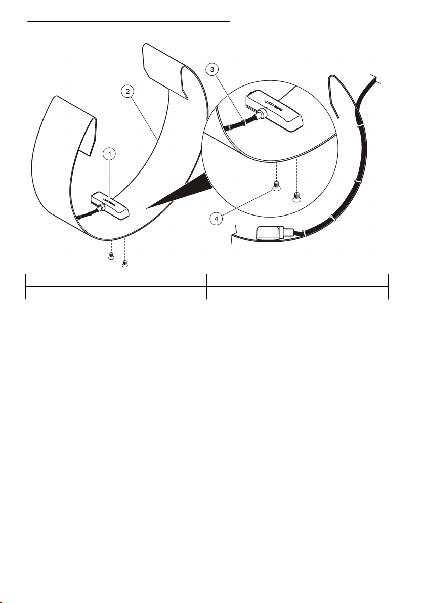
Figure 6 Fixation du capteur à la bande de montage
1 Capteur 3 Câble du capteur
2 Bande de montage 4 Vis (2)
Installation du capteur et de la bande de montage dans le tuyau
1. Positionnez le capteur dans l'écoulement. Figure 7 illustre une configuration en amont standard,
une configuration en aval standard et une configuration capteur inversé en aval.
Pour déterminer la meilleure configuration selon le site, reportez-vous à Tableau 1. Pour plus
d'informations sur les configurations, reportez-vous au manuel de l'enregistreur correspondant.
2. Faites glisser la bande de montage le plus loin possible à l'intérieur du tuyau pour éviter un
rabattement à proximité de l'extrémité du tuyau.
3. Placez le capteur au point le plus bas du canal. S'il y a trop de boue au bas du tuyau, tournez la
bande dans le tuyau jusqu'à ce que le capteur sorte de la boue. Reportez-vous à Figure 8.
32
Français
Page 33

Figure 7 Positions du capteur
1 En amont, face à l'écoulement 2 En aval, face à l'écoulement, 3 En aval, inversé
Tableau 1 Sélection du sens de la sonde
Option Description
En amont Recommandé pour la plupart des applications. L'écoulement sur le capteur doit être aussi droit
En aval Utilisez cette option lorsque le capteur est installé en aval du point de mesure (là où
En aval (capteur
inversé)
que possible, sans chute ni virage à proximité du point de mesure.
Montez le capteur dans le tuyau, le bord biseauté dirigé vers l'écoulement entrant dans la zone
de mesure.
l'écoulement sort du site). Cette option est utile quand plusieurs écoulements pénètrent sur un
site et que le flux combiné de tous les écoulements est mesuré au même point de sortie. Vous
pouvez aussi utiliser cette option si un circuit hydraulique empêche le montage du capteur en
amont.
Montez le capteur face à l'écoulement.
Utilisez cette option lorsque l'option B ne fonctionnera pas en raison d'un manque d'uniformité
de l'écoulement dans la voûte. Avec ce type d'installation, la vitesse de lecture maximale est
de 5 i/s sans le module d'interface AV9000. Montez le capteur en aval. Le fabricant
recommande de vérifier la vitesse avec un profil de l'écoulement et un multiplieur de vitesse
sur site si nécessaire pour un relevé plus précis.
Remarque : Quand le module d'interface AV9000 et le capteur AV immergé sont utilisés avec l'enregistreur
FL900, l'utilisateur a la possibilité de sélectionner Reversed Sensor (Capteur inversé) dans le menu de
configuration du port de capteur (Sensor Port Set Up).
Français 33
Page 34
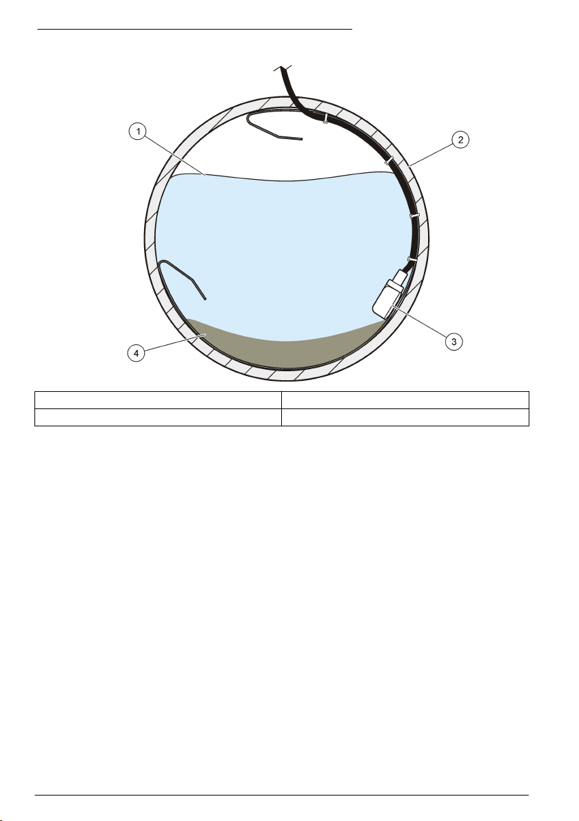
Figure 8 Prévention de la boue lors du montage du capteur
1 Eau 3 Capteur
2 Tube 4 Boue
Fonctionnement
Pour les capteurs connectés à un enregistreur de débit FL900, connectez un ordinateur exécutant le
logiciel FSDATA Desktop à l'enregistreur de débit pour configurer, calibrer et collecter des données
provenant des capteurs. Reportez-vous à la documentation du logiciel FSDATA Desktop pour
configurer, calibrer et collecter des données provenant du capteur.
Pour les capteurs connectés à un enregistreur de débit FL1500, reportez-vous à la documentation de
l'enregistreur de débit FL1500 pour configurer, calibrer et collecter des données provenant des
capteurs. Vous pouvez également raccorder un ordinateur exécutant le logiciel FSDATA Desktop à
l'enregistreur de débit pour configurer, calibrer et collecter des données provenant des capteurs.
Reportez-vous à la documentation du logiciel FSDATA Desktop pour configurer, calibrer et collecter
des données provenant du capteur.
Pour les capteurs raccordés à un échantillonneur AS950, reportez-vous à la documentation de
l'échantillonneur pour la configuration, la calibration et la collecte de données provenant des
capteurs.
Pour les capteurs connectés à un débitmètre Sigma 910, 911, 920, 930 ou 940, connectez un
ordinateur exécutant le logiciel InSight au débitmètre Sigma pour configurer, calibrer et collecter des
données provenant des capteurs.
Installation du logiciel
Assurez-vous que la dernière version du logiciel FSDATA Desktop ou du logiciel InSight est installée
sur l'ordinateur, le cas échéant. Téléchargez le logiciel depuis le site http://www.hachflow.com.
Cliquez sur Support (Aide), puis sélectionnez Software Downloads (Téléchargements de logiciels).
34
Français
Page 35
Configuration du capteur
Pour les capteurs connectés à un enregistreur de débit FL900, configurez les capteurs avec
l'assistant de configuration du logiciel FSDATA Desktop Pour obtenir des instructions, reportez-vous
à la documentation du logiciel FSDATA Desktop.
Pour les capteurs connectés à un enregistreur de débit FL1500 ou à un échantillonneur AS950,
reportez-vous à la documentation de l'échantillonneur ou de l'enregistreur de débit FL1500 pour la
configuration des capteurs. Vous pouvez également vous aider de l'assistant de configuration du
logiciel FSDATA Desktop pour configurer les capteurs lorsque les capteurs sont connectés à un
enregistreur de débit FL1500.
Pour les capteurs connectés à un débitmètre Sigma, effectuez la procédure décrite sous Calibration
de niveau pour les débitmètres Sigma à la page 35.
Remarque : Procédez à une calibration du niveau si le capteur fait l'objet d'un remplacement, d'un retrait à des fins
d'entretien ou d'un déplacement vers un autre instrument.
Calibration de niveau pour les débitmètres Sigma
1. Lorsque le capteur est installé dans l'écoulement, surveillez le statut en cours sur un PC avec le
logiciel Insight ou sur l'écran d'un débitmètre.
2. Mesurez physiquement la distance entre le haut du tuyau et la surface de l'eau. Reportez-vous à
Figure 9.
3. Soustrayez le chiffre de l'étape 2 du diamètre du tuyau. Reportez-vous à Figure 9.
Vous obtenez la profondeur de l'eau. Reportez-vous à Figure 9.
4. Utilisez la fonction de réglage du niveau du logiciel pour saisir la profondeur d'eau mesurée
physiquement.
Figure 9 Mesure du niveau d'eau
1 Niveau d'eau
Français 35
Page 36

Maintenance
A T T E N T I O N
Dangers multiples. Seul le personnel qualifié doit effectuer les tâches détaillées dans cette section du
document.
Nettoyage du capteur
Nettoyez le port du transducteur si :
• Vous constatez des hausses ou baisses impromptues de l'écoulement ou du niveau.
• Les données de niveau sont manquantes ou erronées alors que les données de vitesse sont
valides.
• Des dépôts excessifs de boue s'accumulent entre le transducteur et le couvercle de protection.
Notes
• Ne touchez pas le transducteur du capteur, car vous pourriez endommager et provoquer le
dysfonctionnement du capteur.
• Utilisez uniquement les solutions de nettoyage approuvées répertoriées dans le Tableau 2.
N'utilisez pas de brosse ni de chiffon pour nettoyer le transducteur de pression, car vous pourriez
endommager et provoquer le dysfonctionnement du capteur. En présence de débris, pulvérisez de
l'eau sur la membrane et utilisez un coton-tige pour retirer le dépôt avec précaution.
• Si le joint est manquant ou endommagé, installez-en un nouveau. Un joint manquant ou
endommagé peut entraîner des mesures erronées.
• Après avoir nettoyé le capteur, nettoyez le joint et le couvercle de protection avant de les installer.
• Une fois le capteur à huile nettoyé, refaites le plein d'huile.
• Si vous ne vous servez pas d'un capteur de manière prolongée, ne l'entreposez pas sur une
étagère sèche. Le fabricant recommande d'entreposer le capteur la tête plongée dans de l'eau
pour éviter que les restes d'huile ne se déposent dans le canal du transducteur de pression.
Pour nettoyer le capteur :
1. Plongez le capteur dans de l'eau savonneuse.
2. Retirez les vis du couvercle de protection. Reportez-vous à Figure 10.
3. Déposez le couvercle et le joint. Reportez-vous à Figure 10.
4. Agitez doucement le capteur dans une solution de nettoyage adéquate pour éliminer les saletés.
Utilisez un spray ou un aérosol pour éliminer les dépôts plus lourds.
5. Nettoyez le joint et le couvercle.
6. Fixez le joint et le couvercle. Serrez les vis jusqu'à comprimer légèrement le joint.
36
Français
Page 37

Figure 10 Couvercle de protection et joint du capteur
1 Couvercle de protection 2 Joint 3 Capteur
Tableau 2 Solutions de nettoyage agréées et non agréées
Autorisée Ne pas utiliser
Produit à vaisselle et eau Eau de Javel concentrée
Produit à vitre Kérosène
Alcool isopropylique Essence
Acides dilués Hydrocarbures aromatiques
Remplacement du dessiccant
A V I S
Ne faites pas fonctionner le capteur sans perles de dessiccant, vertes ou pas. Vous risqueriez d'endommager le
capteur de façon permanente.
Remplacez immédiatement le dessiccant lorsqu'il passe au vert. Reportez-vous à Figure 11.
Remarque : Il n'est pas nécessaire de retirer le conteneur de dessiccant du boîtier dessiccant pour installer un
nouveau dessiccant.
A l'étape 5 de la Figure 11, assurez-vous que le joint torique est propre et qu'il ne présente pas de
saletés ou de débris. Examinez le joint torique et vérifiez l'absence de fissures, de piqûres ou de
signes de détérioration. Remplacez le joint torique s'il est endommagé. Appliquez de la graisse sur
les joints toriques secs ou neufs pour faciliter l'installation, obtenir une meilleure étanchéité et
augmenter la durée de vie du joint torique.
Pour des performances optimales, veillez à installer le conteneur de dessiccant à la verticale,
bouchon d'extrémité dirigé vers le bas. Reportez-vous à Fixation du boîtier dessiccant à la page 28.
Remarque : Si les perles commencent à prendre une coloration verte, il est possible de les remettre à neuf en les
chauffant. Retirez les perles de l'absorbeur et chauffez-les à 100-180 °C jusqu'à ce qu'elles deviennent orange. Ne
chauffez pas l'absorbeur. Si les perles ne retrouvent pas leur coloration orange, elles doivent être remplacées par
des billes de dessiccant neuves.
Français
37
Page 38

Figure 11 Remplacement du dessiccant
Remplacement de la membrane hydrophobe
Remplacez la membrane hydrophobe quand :
• des augmentations ou des diminutions inattendues sont observées dans les tendances de niveau ;
• Les données de niveau sont manquantes ou incorrectes, mais les données de vitesse sont
valides.
• La membrane est déchirée ou saturée d'eau ou de graisse.
Reportez-vous à la procédure illustrée ci-après pour remplacer la membrane. A l'étape 4, assurezvous que les points suivants sont validés :
• Le côté lisse de la membrane hydrophobe est appuyé contre la surface interne du conteneur de
dessiccant.
• La membrane hydrophobe se bombe et s'insère complètement dans le filetage, jusqu'à disparaître
complètement.
• La membrane hydrophobe tourne avec le mamelon se trouvant dans le conteneur de dessiccant.
Si la membrane ne tourne pas, elle est endommagée. Répétez alors la procédure avec une
nouvelle membrane.
Pour des performances optimales, veillez à installer le conteneur de dessiccant à la verticale,
bouchon d'extrémité dirigé vers le bas. Reportez-vous à la Fixation du boîtier dessiccant
à la page 28.
38
Français
Page 39
Français 39
Page 40

Remplissage d'huile
Vérifiez que l'huile présente dans le capteur ne contient pas de grosses bulles d'air lors des cycles
d'entretien prévus par le client. De grosses bulles peuvent réduire les propriétés antidépôts de l'huile.
Les petites bulles (< ¼ po. de diamètre) n'affectent pas les propriétés de l'huile.
Pour faire l'appoint en huile du capteur, reportez-vous à la documentation fournie avec le kit de
remplissage d'huile de silicone. Référez-vous à la section Pièces de rechange et accessoires
à la page 40 pour les modalités de commande.
Pièces de rechange et accessoires
A V E R T I S S E M E N T
Risque de blessures corporelles. L'utilisation de pièces non approuvées comporte un risque de
blessure, d'endommagement de l'appareil ou de panne d'équipement. Les pièces de rechange de cette
section sont approuvées par le fabricant.
Remarque : Les numéros de référence de produit et d'article peuvent dépendre des régions de commercialisation.
Prenez contact avec le distributeur approprié ou consultez le site web de la société pour connaître les personnes à
contacter.
Pièces de rechange
Description Référence
Billes de dessiccant, en vrac, réservoir de 1,5 livre 8755500
Conteneur de dessiccant 8542000
Membrane hydrophobe 3390
Joint torique, bouchon d'extrémité du conteneur de dessiccant 1,176 x 0,070 (DI x DE) 5252
Huile de silicone, comprend deux packs d'huile de 50 mL pour remplir 100 capteurs 7724700
Kit de remplissage d'huile de silicone, comprend :
Outil de distribution, deux packs d'huile de 50 mL, fiche d'instructions et matériel divers
Boîtier dessiccant
1
7724800
7722800
Accessoires
Description Référence
Module d'interface AV9000, enregistreurs de débit FL900 8531300
Module d'interface AV9000S avec raccordement de fils dénudés, enregistreurs de débit FL1500 9504601
Module d'interface AV9000S, échantillonneurs portatifs AS950 9504600
Plaque de montage d'accessoires, enregistreurs de débit FL1500 8309300
Câble sur mesure, reliant le capteur à la boîte de jonction, 0,3 à 30 m (1 à 99 pi) 77155-PRB
Câble sur mesure, reliant la boîte de jonction au boîtier dessiccant, 0,3 à 30 m (1 à 99 pi) 77155-HUB
Kit de gel de rempotage en silicone pour boîte de jonction 7725600
Remplissage de gel de rempotage en silicone
Remplissage de gel, pistolet de distribution
2
3
7729800
7715300
1
Utilisation de la référence 77155-HUB pour sélectionner la longueur de câble après le boîtier
dessiccant.
2
Commandez-en trois pour remplir un boîtier de raccordement.
3
Peut également être utilisé en tant que pistolet de remplissage d'huile de silicone
40 Français
Page 41

Description Référence
Kit de modification, remplacement d'un capteur avec plaque de couvercle sans huile par une
7730000
plaque de couvercle remplie d'huile, comprend la référence 7724800
Outil d'insertion, installation au niveau de la rue des bagues de montage 9574
Bague de montage pour conduite de 15,24 cm (6 po.) de diamètre
Bague de montage pour conduite de 20,32 cm (8 po.) de diamètre
Bague de montage pour conduite de 25,40 cm (10 po.) de diamètre
Bague de montage pour conduite de 30,48 cm (12 po.) de diamètre
Bague de montage pour conduite de 38,10 cm (15 po.) de diamètre
Bague de montage pour conduite de 45,72 cm (18 po.) de diamètre
Bague de montage pour conduites de 50,8 à 53,34 cm (20 à 21 po.) de diamètre
Bague de montage pour conduite de 61 cm (24 po.) de diamètre
4
4
4
5
5
5
5
5
1361
1362
1363
1364
1365
1366
1353
1370
Tableau de sélection de la bande de montage
Diamètre de la
canalisation
Référence de
1473--6,25"
(15,85 cm) de long,
ajoutez 2"
(5,08 cm) au
diamètre de la
bande
Sélection de la bande de montage
Référence de
1525--9,5"
(24,13 cm) de
long, ajoutez 3"
(7,62 cm) au
diamètre de la
bande
Référence
1759--19"
(48,26 cm) de
long, ajoutez 6"
(15,24 cm) au
diamètre de la
bande
8" (20,32 cm) 0 0 1 0
10" (25,4 cm) 1 0 1 0
12" (30,48 cm) 0 1 1 0
15" (38,1 cm) 0 2 1 0
18" (45,72 cm) 0 1 2 0
21" (53,34 cm) 0 2 2 0
24" (60,96 cm) 0 1 3 0
27" (68,58 cm) 1 0 1 1
30" (76,2 cm) 1 1 1 1
33" (83,2 cm) 1 0 2 1
36" (91,44 cm) 1 1 2 1
42" (1,06 m) 1 1 3 1
45" (1,14 m) 1 1 1 2
48" (1,21 m) 1 0 2 2
6
Référence
1318--50.25"
(127 cm) de long,
ajoutez 16"
(40,64 cm) au
diamètre de la
bande
4
Exige la référence 3263
5
Le capteur est fixé directement à la bande.
6
En plus des segments de bande indiqués ci-dessous, vous avez besoin d'un clip de montage
pour capteur AV (3263) et d'une prise jack en ciseaux (3719) pour disposer d'une bande de
montage complète.
Français 41
Page 42

Tabla de contenidos
Especificaciones en la página 42 Funcionamiento en la página 54
Información general en la página 43 Mantenimiento en la página 56
Instalación en la página 47 Piezas de repuesto y accesorios en la página 60
Especificaciones
Las especificaciones están sujetas a cambios sin previo aviso.
Especificaciones: sensor sumergido de área velocidad
El rendimiento dependerá del tamaño y la forma del canal, así como de las condiciones de la
instalación.
Medición de velocidad
Método Ultrasónico Doppler
Tipo de transductor: Cristal piezoeléctrico de 1 MHz doble
Profundidad mínima normal para
la velocidad
Rango -1,52 a 6,10 m/s (-5 a 20 pies/s)
Exactitud ± 2% de lectura (en agua con un perfil de velocidad uniforme)
Medición del nivel
Método Transductor para medir presiones con diafragma de acero inoxidable
Exactitud (estática)
2 cm (0.8 pulgadas)
• ±0,16% de escala completa ±1,5% de lectura a temp. constante (±2,5 ºC)
• ±0,20% de escala completa ±1,75% de lectura de 0 a 30 ºC (de 32 a
86 ºF)
• ±0,25% de escala completa ±2,1% de lectura de 0 a 70 ºC (de 32 a
158 ºF)
Error de profundidad inducido por
la velocidad
Intervalo del nivel
Nivel admisible
Atributos generales
Toma de aire La referencia de la presión atmosférica está protegida con desecante
Temperatura de funcionamiento 0 a 70 ºC (32 a 158 ºF)
Intervalo de temperatura
compensada del nivel
Material Capa exterior de Noryl® con encapsulado interior de epoxi
Consumo de energía Menor o igual a 1,2 W a 12 V CC
Cable Cable de uretano del sensor con orificio de ventilación
Conector Anodizado duro, cumple la especificación militar 5015
Compensado según la velocidad del flujo
• Estándar: entre 0 y 3 m (entre 0 y 10 pies)
• Ampliado: entre 0 y 9 m (entre 0 y 30 pies)
• Estándar: 10,5 m (34,5 pies)
• Ampliado: 31,5 m (103,5 pies)
0 a 70 ºC (32 a 158 ºF)
42 Español
Page 43

Longitudes de cable disponibles
Diámetro del cable 0,91 cm (0,36 pulgadas)
Dimensiones 2,3 cm de alto x 3,8 cm de ancho x 13,5 cm de largo (0,9 pulg. de alto x
Instrumentos compatibles Tomamuestras Sigma 910, 920, 930, 930 T, 950, 900 Max y módulos de
• Estándar: 9, 15, 23 y 30,5 m (30, 50, 75, 100 pies)
• Personalizado: de 30,75 m (101 pies) a 76 m (250 pies) como máximo
1,5 pulg. de ancho x 5,31 pulg. de largo)
interfaz AV9000 para registradores de caudal de la serie FL o tomamuestras
AS950
Especificaciones: módulo de interfaz AV9000
Medición de velocidad
Método de medición Ultrasonido Doppler de 1 MHz
Tipo de análisis Doppler Análisis espectral digital
-1,52 a 6,10 m/s (-5 a 20 pies/s)
± 2% de lectura o 0,015 m/s (0,05 fps) (perfil de velocidad uniforme,
salinidad conocida, flujo positivo. El rendimiento en campo depende de las
condiciones específicas de la instalación.)
Exactitud del Doppler ±1% de lectura o 0,076 m/s (0,025 fps) (con señal de Doppler con
Requisitos de alimentación
Tensión de alimentación 9-15 V CC
Corriente máxima <130 mA a 12 V CC con sensor sumergido de área velocidad
Energía por medición <15 julios (normalmente)
Temperatura de funcionamiento
-18 a 60 ºC (0 a 140 ºF) a 95% HR
Carcasa
Dimensiones (an. x alt. x prof.) AV9000: 13 x 17,5 x 5 cm (5,0 x 6,875 x 2,0 pulg.)
Clasificación medioambiental NEMA 6P, IP 68
Material de la caja PC/ABS
simulación electrónica, velocidad equivalente de -7,6 a +7,6 m/s (-25 a
+25 fps). Consulte Configuración del sensor en la página 55.
AV9000S: 12,01 x 14,27 x 6,86 cm (4,73 x 5,62 x 2,70 pulg.)
Información general
En ningún caso el fabricante será responsable de ningún daño directo, indirecto, especial, accidental
o resultante de un defecto u omisión en este manual. El fabricante se reserva el derecho a modificar
este manual y los productos que describen en cualquier momento, sin aviso ni obligación. Las
ediciones revisadas se encuentran en la página web del fabricante.
Información de seguridad
A V I S O
El fabricante no es responsable de ningún daño debido a un mal uso de este producto incluyendo, sin limitación,
daños directos, fortuitos o circunstanciales y reclamaciones sobre los daños que no estén recogidos en la
legislación vigente. El usuario es el responsable de la identificación de los riesgos críticos y de tener los
mecanismos adecuados de protección de los procesos en caso de un posible mal funcionamiento del equipo.
Español 43
Page 44

Lea todo el manual antes de desembalar, instalar o trabajar con este equipo. Ponga atención a
todas las advertencias y avisos de peligro. El no hacerlo puede provocar heridas graves al usuario o
daños al equipo.
Asegúrese de que la protección proporcionada por el equipo no está dañada. No utilice ni instale
este equipo de manera distinta a lo especificado en este manual.
Uso de la información sobre riesgos
P E L IG R O
Indica una situación potencial o de riesgo inminente que, de no evitarse, provocará la muerte o lesiones graves.
A D V E R T E N C I A
Indica una situación potencial o inminentemente peligrosa que, de no evitarse, podría provocar la muerte o
lesiones graves.
P R E C A U C I Ó N
Indica una situación potencialmente peligrosa que podría provocar una lesión menor o moderada.
Indica una situación que, si no se evita, puede provocar daños en el instrumento. Información que requiere
especial énfasis.
A V I S O
Etiquetas de precaución
Lea todas las etiquetas y rótulos adheridos al instrumento. En caso contrario, podrían producirse
heridas personales o daños en el instrumento. El símbolo que aparezca en el instrumento se
comentará en el manual con una declaración de precaución.
Este es un símbolo de alerta de seguridad. Obedezca todos los mensajes de seguridad que se
muestran junto con este símbolo para evitar posibles lesiones. Si se encuentran sobre el instrumento,
consulte el manual de instrucciones para obtener información de funcionamiento o seguridad.
Este símbolo indica la presencia de dispositivos susceptibles a descargas electrostáticas. Asimismo,
indica que se debe tener cuidado para evitar que el equipo sufra daño.
En Europa, el equipo eléctrico marcado con este símbolo no se debe desechar mediante el servicio
de recogida de basura doméstica o pública. Devuelva los equipos viejos o que hayan alcanzado el
término de su vida útil al fabricante para su eliminación sin cargo para el usuario.
Precauciones para espacios confinados
P E L IG R O
Peligro de explosión. La formación en las pruebas previas a la entrada, la ventilación, los
procedimientos de acceso, los procedimientos de evacuación/rescate y las prácticas de trabajo de
seguridad es necesaria antes de introducirlo en espacios cerrados.
La información que se incluye a continuación se ofrece para ayudar a los usuarios a comprender los
peligros y riesgos asociados a los espacios confinados.
El 15 de abril de 1993, el dictamen definitivo de la OSHA (Administración de Seguridad y Salud
Ocupacional) sobre los Espacios Confinados que Requieren Permiso para Ingresar (CFR 1910.146),
se hizo ley. Esta nueva norma afecta directamente a más de 250.000 sitios industriales de los
Estados Unidos, y fue creada con el fin de proteger la salud y la seguridad de los trabajadores en
espacios confinados.
Definición de espacio confinado:
Un espacio confinado es cualquier lugar o recinto que presente (o tenga la posibilidad inmediata de
presentar) una o más de las siguientes condiciones:
44
Español
Page 45

• Una atmósfera con una concentración de oxígeno que sea inferior al 19,5% o superior al 23,5%
y/o una concentración de sulfuro de hidrógeno (H2S) superior a 10 ppm.
• Una atmósfera que pueda ser inflamable o explosiva debido a gases, vapores, nieblas, polvos o
fibras.
• Materiales tóxicos que, ante el contacto o la inhalación, puedan provocar lesiones, el deterioro de
la salud o la muerte.
Los espacios confinados no están destinados a ser ocupados por seres humanos. Los espacios
confinados tienen entrada restringida y contienen riesgos conocidos o potenciales. Como ejemplos
de espacios confinados encontramos las bocas de inspección, las chimeneas, los caños, las tinas,
los armarios de distribución y demás lugares similares.
Antes de entrar en espacios confinados y/o lugares con presencia de gases, vapores, nieblas,
polvos o fibras peligrosos, se deben seguir siempre procedimientos de seguridad estándares. Antes
de entrar en un espacio confinado, lea todos los procedimientos relacionados con la entrada a
espacios confinados.
Descripción general del producto
El sensor área velocidad (AV) se utiliza con caudalímetros Sigma, registradores de caudal de la
serie FL y tomamuestras AS950 para medir el caudal en canales abiertos. Consulte la Figura 1.
El sensor se encuentra disponible en versiones con aceite y sin aceite. El sensor sin aceite se utiliza
en instalaciones bastante limpias o en instalaciones en las que la tubería podría estar seca. El
sensor con aceite se emplea en instalaciones con elevados niveles de desarrollo de
microorganismos, arena o limo.
Nota: No utilice un sensor con aceite en una tubería que podría estar seca.
El sensor sumergido AV se conecta a un registrador de caudal de la serie FL o tomamuestras
AS950 a través de un módulo de interfaz AV9000. Consulte Piezas de repuesto y accesorios
en la página 60 para identificar el modelo AV9000 aplicable para el registrador de caudal o
tomamuestras.
Nota: El sensor sumergido AV se conecta directamente a los caudalímetros Sigma. No es necesario un módulo de
interfaz AV9000.
Español
45
Page 46

Figura 1 Sensor área velocidad
1 Caja de conexiones (opcional) 6 Cordón
2 Conjunto de desecante 7 Sensor sumergido AV
3 Depósito de desecante 8 Mosquetón
4 Tubo de referencia de aire 9 Cable del sensor
5 Conector
Teoría de operación
El sensor funciona como un sensor área velocidad y sigue la ecuación de continuidad.
Caudal = área húmeda x velocidad media
Un transductor de presión del sensor transforma la presión del agua en una medición del nivel. La
medición del nivel y la geometría del canal indicada por el usuario se emplean para calcular el área
húmeda del flujo.
El sensor también contiene dos transductores ultrasónicos: uno es un transmisor y otro es un
receptor. Se transmite una señal de 1 MHz y se refleja en las partículas en la corriente de flujo. Se
recibe la señal reflejada y su frecuencia se compensa por el desplazamiento Doppler proporcional a
la velocidad de las partículas en la corriente de flujo. El registrador de caudal transforma el
desplazamiento Doppler de las señales de ultrasonido que son devueltas en una medición de la
velocidad.
Componentes del producto
En la Figura 2 se muestran los artículos del paquete. Póngase en contacto con el fabricante si falta
algún componente o está dañado.
46
Español
Page 47

Figura 2 Componentes del producto
1 Sensor sumergido AV 3 Caja de conexión
2 Sensor sumergido AV con caja de conexión 4 Tornillos de montaje (6x)
Instalación
Guía para la instalación
P E L IG R O
Peligro de explosión Los sensores AV sin seguridad intrínseca (artículos 770xx-xxx) no están diseñados para su
uso en ubicaciones peligrosas. Para las ubicaciones peligrosas, debe emplear sensores AV con seguridad
intrínseca (artículos 880xx-xxx) instalados de acuerdo con los esquemas de control de los manuales de los
medidores de flujo sin indicación de resultado con seguridad intrínseca 911/940.
P E L IG R O
Existen riesgos en espacios reducidos. Las tareas descritas en esta sección del manual solo deben ser
realizadas por personal cualificado.
• No instale más de un sensor en tuberías de un diámetro inferior a 61 cm (24 pulgadas). Si hay
instalados varios sensores en tuberías más pequeñas, es posible que aumente la velocidad del
flujo o se produzcan turbulencias cerca de los sensores, de modo que las mediciones pueden ser
imprecisas.
• Coloque el sensor tan cerca del fondo de la tubería como sea posible. De esta forma obtendrá las
mediciones del nivel a velocidad baja más precisas.
• No lleve a cabo la medición del flujo en la parte interior del pozo de inspección. La mejor
ubicación del sensor es entre 3 y 5 veces la altura/el diámetro de la alcantarilla en la zona
ascendente de la parte interior.
• Sitúe los puntos de medición lo más lejos posible de las uniones de flujo entrante para evitar las
interferencias causadas por los caudales combinados.
• Los objetos como piedras, juntas de la tubería o vástagos de válvula crean turbulencias y generan
flujos de alta velocidad cerca del objeto. Asegúrese de que no hay ninguna obstrucción en la zona
equivalente a entre 2 y 4 diámetros de la tubería delante del punto de instalación del sensor. Se
obtiene la máxima precisión cuando no hay interrupciones de flujo en una zona equivalente a
entre 5 y 10 diámetros de la tubería.
• No utilice instalaciones con flujos de baja velocidad que crean acumulaciones de limo en la parte
interior o en el canal. La acumulación de limo cerca del sensor puede inhibir la señal de Doppler y
hacer que las lecturas del sensor y las mediciones de profundidad no sean precisas.
• No utilice instalaciones con flujos rápidos y profundos en los que la instalación del sensor
resultaría difícil y peligrosa
Español
47
Page 48

• No utilice instalaciones con flujos de gran velocidad y poca profundidad. Las salpicaduras y las
turbulencias excesivas alrededor del sensor pueden afectar a la precisión de los datos.
Interferencia
El módulo de interfaz AV9000 incluye un receptor de radiofrecuencia sensible con capacidad para
detectar señales muy bajas. Cuando se conectan a las comunicaciones o puertos auxiliares de
alimentación de un registrador de caudal o tomamuestras, algunos equipos con línea de
alimentación pueden añadir ruido eléctrico que interfiere con las mediciones de velocidad Doppler.
No es habitual que se produzcan interferencias con las mediciones en las instalaciones normales.
El AV9000 es más sensible al ruido que se produce en el intervalo de análisis Doppler de 1 MHz
±13,3 kHz. El ruido en otras frecuencias generalmente no causa interferencias.
Algunos ordenadores portátiles pueden provocar interferencias cuando han utilizado adaptadores
externos de corriente CA. Si dicho dispositivo afecta a las mediciones, utilice el ordenador portátil
con batería o desconecte el cable entre el ordenador portátil y el registrador de caudal o
tomamuestras.
Instale el módulo de interfaz AV9000
El sensor sumergido AV se conecta a un registrador de caudal de la serie FL o tomamuestras
AS950 a través de un módulo de interfaz AV9000. Consulte Piezas de repuesto y accesorios
en la página 60 para identificar el módulo de interfaz AV9000 aplicable para el registrador de
caudal o tomamuestras.
Nota: El sensor sumergido AV se conecta directamente a los caudalímetros Sigma. No es necesario un módulo de
interfaz AV9000.
1. Instale el módulo de interfaz AV9000. Consulte la documentación del AV9000 para obtener
instrucciones.
2. Conecte el cable del sensor al módulo de interfaz AV9000. Consulte la documentación del
AV9000 para obtener instrucciones.
3. Conecte el cable del AV9000 a un puerto del sensor (o terminal) en el registrador de caudal o el
tomamuestras. Consulte la documentación del registrador de caudal o el tomamuestras para
obtener instrucciones.
Fije el conjunto de desecante
Fije el conjunto de desecante al registrador de caudal o tomamuestras para liberar la tensión del
sensor y del conector del cable. Consulte de la Figura 3 a la Figura 5.
Para obtener el mejor rendimiento, asegúrese de instalar el cartucho de desecante verticalmente
con la tapa del extremo apuntando hacia abajo. Consulte de la Figura 3 a la Figura 5.
48
Español
Page 49

Figura 3 Fije el conjunto de desecante: registrador de caudal FL900
1 Tapa final
Figura 4 Fije el conjunto de desecante: registrador de caudal FL1500
1 AV9000S con conexión de cables desnudos 3 Tapa final
2 Placa de montaje para accesorios
Español 49
Page 50

Figura 5 Fije el conjunto de desecante: tomamuestras portátil AS950
1 Tapa final
Calibración de cero
Si una o más de las siguientes indicaciones son correctas, realice una calibración de cero antes de
instalar el sensor.
• La ubicación de la instalación es un canal seco.
• No es posible obtener un nivel exacto en el flujo porque el nivel cambia demasiado rápido.
• No es posible obtener un nivel exacto en el flujo debido a peligros físicos.
Nota: El sensor está calibrado en fábrica para la temperatura y el intervalo especificados.
Calibración de cero (registrador de caudal de la serie FL o tomamuestras)
Para realizar una calibración de cero con un registrador de caudal FL900, realice una calibración de
cero (calibración de cero en aire) con el asistente de instalación FSDATA Desktop. Consulte la
documentación de FSDATA Desktop para obtener instrucciones. Como alternativa, realice una
calibración de cero manual (calibración de cero en aire) con FSDATA Desktop.
Para realizar una calibración de cero con el registrador de caudal FL1500 o tomamuestras, consulte
la documentación del registrador de caudal FL1500 o tomamuestras para obtener instrucciones.
Como alternativa, realice una calibración de cero con el asistente de instalación FSDATA Desktop
cuando el sensor esté conectado a un registrador de caudal FL1500.
Asegúrese de que el sensor está fuera del agua y en una superficie plana, nivelada y horizontal.
Nota: Si el sensor se sustituye, se retira para su mantenimiento o se traslada a otro equipo, realice una calibración
de cero.
50
Español
Page 51

Calibración de cero (caudalímetros de Sigma 910 a 950)
Realice una calibración de cero de la siguiente manera:
Nota: Si el sensor se sustituye, se retira para su mantenimiento o se traslada a otro equipo, vuelva a realizar una
calibración de cero.
1. Conecte el caudalímetro en un equipo con el software InSight. Consulte la documentación del
caudalímetro para obtener instrucciones.
2. Inicie el software InSight en el ordenador.
3. Seleccione Remote Programming (Programación remota).
4. En la lista Real Time Operations (Operaciones en tiempo real), seleccione el sensor de nivel.
5. Saque la sonda del líquido y coloque el sensor en posición recta sobre la mesa o en el suelo con
el sensor (la placa con orificios) orientado hacia abajo.
6. Pulse OK (Aceptar) en el cuadro de diálogo cuando haya acabado.
Fijación del sensor a la banda de montaje
Las bandas de montaje disponen de orificios previamente realizados para permitir el montaje directo
del sensor en la banda. Consulte los pasos y las figuras para montar el sensor en la banda de
montaje.
Nota: Si el sensor es de los que se llenan con aceite, asegúrese de que tiene aceite antes de montarlo en la banda
de montaje. Consulte el apartado sobre el llenado de aceite del sensor de este manual.
1. Fije el sensor al anillo de resorte Figura 6. Monte los sensores de modo que el transductor de
presión sobresalga del anillo.
2. Coloque el cable a lo largo del borde de la banda (Figura 6).
3. Utilice amarres de nylon para sujetar el cable a la banda de montaje.
El cable debe salir de la zona atada por el extremo de la tubería o cerca de este punto.
Nota: Si hay una gran cantidad de limo en el fondo de la tubería, gire la banda hasta que el sensor salga del
limo (Figura 8 en la página 54). Asegúrese de que el sensor permanece siempre por debajo del nivel mínimo
de agua esperado. El limo se debe medir con frecuencia, pero no se debe modificar.
Español
51
Page 52

Figura 6 Fije el sensor a la banda de montaje
1 Sensor 3 Cable del sensor
2 Anillo de resorte 4 Tornillos (2)
Colocación del sensor y la banda de montaje en la tubería
1. Coloque el sensor en el flujo. En la Figura 7 se muestra una configuración ascendente estándar,
una configuración descendente estándar y una configuración descendente del sensor en la
dirección del flujo.
Para elegir la configuración que mejor se adapta a la instalación, consulte la Tabla 1. Para
obtener más información acerca de la configuración, consulte el manual del registrador
apropiado.
2. Deslice la banda de montaje hacia la tubería hasta el tope para evitar un descenso del nivel al
final de la tubería.
3. Coloque el sensor en el punto más profundo del canal. Si hay demasiado limo en el fondo de la
tubería, gire la banda de la tubería hasta que el sensor salga del limo. Consulte la Figura 8.
52
Español
Page 53

Figura 7 Posiciones del sensor
1 Ascendente, en dirección
contraria al flujo
2 Descendente, en dirección
contraria al flujo
3 Descendente, en la dirección del
flujo
Tabla 1 Selección de la dirección de la sonda
Opción Descripción
Ascendente Se recomienda para la mayoría de aplicaciones. El caudal que pasa por el sensor debe
Descendente Utilice esta opción cuando el sensor esté instalado en la zona descendente del punto de
Descendente
(sensor en la
dirección del flujo)
fluir lo más recto posible, sin desniveles ni giros cerca del punto de medición.
Monte el sensor en la tubería con el borde biselado en dirección hacia el flujo en el punto
en que el caudal llega al área de medición.
medición (donde el caudal abandona la instalación). Esta opción resulta útil cuando a la
instalación llegan varios flujos y el caudal combinado de todos los flujos se mide en un
único punto de salida. Esta opción también se puede emplear si hay que algún sistema
hidráulico que no permita que el sensor se monte en la zona ascendente.
Monte el sensor en dirección contraria al flujo.
Utilice esta opción cuando la opción B no funcione porque el flujo no es uniforme en el
depósito. La lectura de velocidad máxima en este tipo de instalación es de 5 fps cuando
no se utiliza el módulo de interfaz AV9000. Monte el sensor en la zona descendente. El
fabricante recomienda verificar la velocidad mediante un perfil del flujo y un multiplicador
de velocidad de la instalación, si es necesario, para obtener una lectura más precisa.
Nota: Si utiliza el módulo de interfaz AV9000 y el sensor sumergido AV con el registrador FL900, el
usuario tendrá la opción de seleccionar Reversed Sensor (Sensor en la dirección del flujo) en el menú
Sensor Port Set Up (Configuración del puerto del sensor).
Español 53
Page 54

Figura 8 Evitar el limo durante el montaje del sensor
1 Agua 3 Sensor
2 Tubería 4 Limo
Funcionamiento
Para sensores conectados a un registrador de caudal FL900, conecte un ordenador con el software
FSDATA Desktop al registrador de caudal para configurar, calibrar y recopilar datos de los sensores.
Consulte la documentación de FSDATA Desktop para configurar, calibrar y recopilar datos del
sensor.
Para sensores conectados a un registrador de caudal FL1500, consulte la documentación del
registrador de caudal FL1500 para configurar, calibrar y recopilar datos de los sensores. Como
alternativa, conecte un ordenador con el software FSDATA Desktop al registrador de caudal para
configurar, calibrar y recopilar datos de los sensores. Consulte la documentación de FSDATA
Desktop para configurar, calibrar y recopilar datos del sensor.
Para sensores conectados a un tomamuestras AS950, consulte la documentación del tomamuestras
AS950 para configurar, calibrar y recopilar datos de los sensores.
Para sensores conectados a un caudalímetro Sigma 910, 911, 920, 930 o 940, conecte un
ordenador con el software InSight al caudalímetro Sigma para configurar, calibrar y recopilar datos
de los sensores.
Instale el software
Asegúrese de que la última versión del software FSDATA Desktop o del software InSight está
instalada en el ordenador, según corresponda. Descárguese el software de
http://www.hachflow.com. Haga clic en Support (Asistencia técnica) y, a continuación, seleccione
Software Downloads (Descargas de software).
54
Español
Page 55
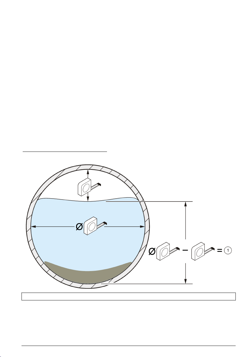
Configuración del sensor
Para sensores conectados a un registrador de caudal FL900, configure los sensores con el asistente
de instalación FSDATA Desktop. Consulte la documentación de FSDATA Desktop para obtener
instrucciones.
Para sensores conectados a un registrador de caudal FL1500 o tomamuestras AS950, consulte la
documentación del tomamuestras o del registrador de caudal FL1500 para configurar los sensores.
Como alternativa, configure los sensores con el asistente de instalación FSDATA Desktop cuando
los sensores están conectados a un registrador de caudal FL1500.
Para sensores conectados a un caudalímetro Sigma, siga los pasos en Calibración de nivel para
caudalímetros Sigma en la página 55.
Nota: Si un sensor se sustituye, se retira para su mantenimiento o se traslada a otro equipo, realice una
calibración de nivel.
Calibración de nivel para caudalímetros Sigma
1. Con el sensor instalado en el flujo, controle el estado de la corriente mediante un PC a través del
software Insight o de la pantalla de un medidor de flujo.
2. Mida físicamente la distancia desde la parte superior de la tubería hasta la superficie del agua.
Consulte la Figura 9.
3. Reste el valor obtenido en el paso 2 al diámetro de la tubería. Consulte la Figura 9.
El resultado es la profundidad del agua. Consulte la Figura 9.
4. Utilice la función Adjust Level (Ajustar nivel) del software para introducir la profundidad del agua
que ha medido físicamente.
Figura 9 Medición del nivel del agua
1 Nivel del agua
Español 55
Page 56

Mantenimiento
P R E C A U C I Ó N
Peligros diversos. Sólo el personal cualificado debe realizar las tareas descritas en esta sección del
documento.
Limpiar el sensor
Limpie el puerto del transductor cuando:
• aumente o disminuya de forma inesperada el flujo o se produzcan tendencias de nivel
• se pierdan los datos de nivel o estos sean incorrectos, mientras que los datos de velocidad sean
válidos
• se acumulen demasiados depósitos de limo entre el transductor y la cubierta de protección
Notas
• No toque el transductor del sensor, ya que el sensor podría funcionar de forma incorrecta o se
podrían producir daños.
• Utilice solamente las soluciones limpiadoras aprobadas que se incluyen en la Tabla 2. No utilice
ningún tipo de cepillo o trapo para limpiar el transductor de presión, ya que el sensor podría
funcionar de forma incorrecta o se podrían producir daños. Si hay restos, pulverice agua en la
membrana y utilice un hisopo para retirar con cuidado la acumulación.
• Si la junta está dañada o no está instalada, coloque una nueva. Si la junta está dañada o no está
instalada, las lecturas obtenidas no serán precisas.
• Tras limpiar el sensor, limpie la junta y la cubierta de protección antes de instalarlas.
• Tras limpiar un sensor de los que emplean aceite, llénelo de aceite.
• Si el sensor no se va a utilizar durante un largo periodo de tiempo, no debe almacenarlo en una
estantería en un lugar seco. El fabricante recomienda que el sensor se almacene con el cabezal
en un cubo de agua para evitar que los restos de aceite formen una capa en el canal del
transductor de presión.
Para limpiar el sensor:
1. Sumerja el sensor en agua con jabón.
2. Retire los tornillos de la cubierta de protección. Consulte la Figura 10.
3. Quite la cubierta y la junta. Consulte la Figura 10.
4. Agite con cuidado el sensor en una solución limpiadora adecuada para eliminar la tierra. Utilice
un pulverizador o una botella de plástico para eliminar los depósitos más pesados.
5. Limpie la junta y la cubierta.
6. Coloque la junta y la cubierta. Apriete los tornillos hasta que la junta comience a comprimirse.
56
Español
Page 57

Figura 10 Cubierta de protección y junta del sensor
1 Tapa protectora 2 Junta 3 Sensor
Tabla 2 Soluciones limpiadoras aceptables y no aceptables
Aceptable No aceptable
Lavavajillas y agua Lejía (soda cáustica) concentrada
Limpiacristales Queroseno
Alcohol isopropílico Gasolina
Ácidos diluidos Hidrocarburos aromáticos
Cambio del desecante
A V I S O
No utilice el sensor sin bolas de desecante o con bolas de desecante verdes. Se pueden producir daños
permanentes en el sensor.
Sustituya inmediatamente el desecante cuando cambie a verde. Consulte la Figura 11.
Nota: No es necesario retirar el depósito de desecante del conjunto de desecante para instalar un desecante
nuevo.
En el paso 5 de la Figura 11, asegúrese de que la junta tórica está limpia y no tiene suciedad ni
residuos. Examine la junta tórica para comprobar si presenta grietas, fisuras o signos de daños.
Sustituya la junta tórica si presenta daños. Aplique grasa a las juntas tóricas secas o nuevas para
facilitar la instalación, sellar mejor e incrementar su vida útil.
Para obtener el mejor rendimiento, asegúrese de instalar el depósito de desecante verticalmente con
la tapa del extremo apuntando hacia abajo. Consulte la sección Fije el conjunto de desecante
en la página 48.
Nota: En el momento en que las perlas comienzan a volverse verdes, puede revitalizarlas aplicándoles calor.
Sáquelas del cartucho y caliéntelas a 100-180 ºC (212-350 ºF) hasta que vuelvan a ponerse de color naranja. No
caliente el cartucho. Si las perlas no se vuelven naranjas, debe cambiarlas por un desecante nuevo.
Español
57
Page 58
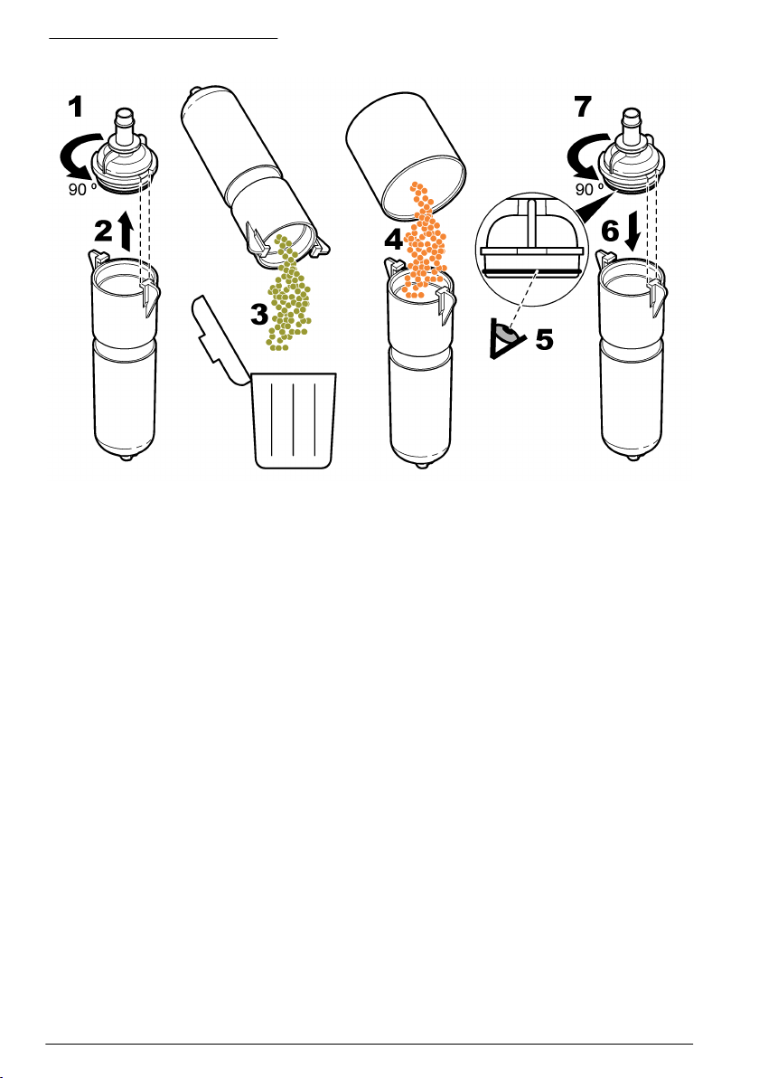
Figura 11 Cambio del desecante
Sustitución de la membrana hidrófoba
Sustituya la membrana hidrófoba cuando:
• Aumenten o disminuyan de forma inesperada las tendencias de nivel.
• Se pierdan los datos de nivel o estos sean incorrectos, pero los datos de velocidad sean válidos.
• La membrana esté rota o se haya saturado con agua o grasa.
Consulte los siguientes pasos ilustrados para sustituir la membrana. En el paso 4, asegúrese de que
ocurra lo siguiente:
• La parte lisa de la membrana hidrófoba está contra la superficie interior del depósito de
desecante.
• La membrana hidrófoba se dobla y se introduce completamente en la rosca hasta que no se ve.
• La membrana hidrófoba gira con la boquilla cuando la boquilla del depósito de desecante gira. Si
la membrana no gira, está dañada. Inicie el mismo procedimiento con una membrana nueva.
Para obtener el mejor rendimiento, asegúrese de instalar el cartucho de desecante verticalmente
con la tapa del extremo apuntando hacia abajo. Consulte la Fije el conjunto de desecante
en la página 48.
58
Español
Page 59

Español 59
Page 60

Llenado de aceite del sensor
Inspeccione el aceite del sensor para comprobar si hay burbujas de aire de gran tamaño durante los
ciclos de mantenimiento programados por el cliente. Las burbujas grandes pueden reducir las
propiedades del aceite que evitan que se acumule suciedad. Las burbujas pequeñas (< ¼ pulg. de
diámetro) no afectan a las propiedades del aceite.
Para reponer el aceite del sensor, consulte la documentación suministrada con el kit de llenado de
aceite de silicona. Consulte Piezas de repuesto y accesorios en la página 60 para obtener
información sobre pedidos.
Piezas de repuesto y accesorios
A D V E R T E N C I A
Peligro de lesión personal. El uso de piezas no aprobadas puede causar lesiones personales, daños al
instrumento o un mal funcionamiento del equipo. Las piezas de repuesto que aparecen en esta
sección están aprobadas por el fabricante.
Nota: Los números de producto y artículo pueden variar para algunas regiones de venta. Comuníquese con el
distribuidor correspondiente o visite el sitio Web de la compañía para obtener la información de contacto.
Piezas de repuesto
Descripción Número de artículo
Perlas desecantes, a granel, contenedor de 1,5 libras (0,68 kg) 8755500
Depósito de desecante 8542000
Membrana hidrófoba 3390
Junta tórica, tapa del extremo del depósito de desecante, DI de 3 cm (1,176 pulg.) x DE
de 0,18 cm (0,070 pulg.)
Aceite de silicona, incluye dos paquetes de aceite de 50 ml para rellenar 100 sensores 7724700
Kit de llenado de aceite de silicona que incluye:
herramienta de dispensación, dos paquetes de aceite de 50 ml, hoja de instrucciones y
hardware variado
Conjunto de desecante
1
5252
7724800
7722800
Accesorios
Descripción Número de artículo
Módulo de interfaz AV9000, registradores de caudal FL900 8531300
Módulo de interfaz AV9000S con conexión de cables desnudos, registradores de caudal
FL1500
Módulo de interfaz AV9000S, tomamuestras AS950 9504600
Placa de montaje para accesorios, registradores de caudal FL1500 8309300
Cable personalizado, del sensor a la caja de conexión, de 0,3 a 30 m (de 1 a 99 pies) 77155-PRB
Cable personalizado, de la caja de conexión al conjunto de desecante, de 0,3 a 30 m (de
1 a 99 pies)
Kit de gel de silicona de encapsulación para caja de conexión 7725600
Relleno de gel, encapsulación con silicona
2
9504601
77155-HUB
7729800
1
Utilice la referencia 77155-HUB para seleccionar la longitud del cable desde el conjunto de
desecante.
2
Solicite tres para rellenar una caja de conexiones.
60 Español
Page 61

Descripción Número de artículo
Relleno de gel, pistola dispensadora
Kit de adaptación, cambiar un sensor con una placa de recubrimiento sin aceite a un
3
7715300
7730000
sensor con una placa de recubrimiento con aceite, incluye 7724800
Herramienta de inserción, instalación de anillos de montaje a nivel de calle 9574
Anillo de montaje para tubo de ∅ 15,24 cm (6 pulg.)
Anillo de montaje para tubo de ∅ 20,32 cm (8 pulg.)
Anillo de montaje para tubo de ∅ 25,40 cm (10 pulg.)
Anillo de montaje para tubo de ∅ 30,48 cm (12 pulg.)
Anillo de montaje para tubo de ∅ 38,10 cm (15 pulg.)
Anillo de montaje para tubo de ∅ 45,72 cm (18 pulg.)
Anillo de montaje para tubo de ∅ 50,8 a 53,34 cm (20 a 21 pulg.)
Anillo de montaje para tubo de ∅ 61 cm (24 pulg.)
4
4
4
5
5
5
5
5
1361
1362
1363
1364
1365
1366
1353
1370
Cuadro de selección de la banda de montaje
Diámetro de la
tubería
Artículo 1473--6,25"
(15,85 cm) de
longitud, añade 2"
(5,08 cm) al
diámetro de la
banda
Selección de la banda de montaje
Artículo 1525--9,5"
(24,13 cm) de
longitud, añade 3"
(7,62 cm) al
diámetro de la
banda
Artículo 1759--19"
(48,26 cm) de
longitud, añade 6"
(15,24 cm) al
diámetro de la
banda
8" (20,32 cm) 0 0 1 0
10" (25,4 cm) 1 0 1 0
12" (30,48 cm) 0 1 1 0
15" (38,1 cm) 0 2 1 0
18" (45,72 cm) 0 1 2 0
21" (53,34 cm) 0 2 2 0
24" (60,96 cm) 0 1 3 0
27" (68,58 cm) 1 0 1 1
30" (76,2 cm) 1 1 1 1
33" (83,2 cm) 1 0 2 1
36" (91,44 cm) 1 1 2 1
42" (1,06 m) 1 1 3 1
6
Artículo 1318--50,25"
(127 cm) de
longitud, añade 16"
(40,64 cm) al
diámetro de la
banda
3
También se puede utilizar como pistola de llenado de aceite de silicona
4
Requiere la referencia 3263
5
El sensor se acopla directamente a la banda.
6
Además de los segmentos de banda que se muestran a continuación, para un conjunto
completo de banda de montaje se necesita un clip de montaje del sensor AV (3263) y un
conjunto de gato de tijera (3719).
Español 61
Page 62

45" (1,14 m) 1 1 1 2
48" (1,21 m) 1 0 2 2
62 Español
Page 63

Sommario
Dati tecnici a pagina 63 Funzionamento a pagina 75
Informazioni generali a pagina 64 Manutenzione a pagina 77
Installazione a pagina 68 Parti di ricambio e accessori a pagina 81
Dati tecnici
I dati tecnici sono soggetti a modifica senza preavviso.
Dati tecnici — Sensore a immersione area/velocità
Le prestazioni variano a seconda delle dimensioni e della forma del canale oltre che delle condizioni
dell'area.
Misurazione della velocità
Metodo Ultrasonico doppler
Tipo trasduttore: Coppia cristalli piezoelettrici 1 MHz
Profondità minima tipica per
velocità
Gamma da -1,52 a 6,10 m/s (da -5 a 20 piedi/s)
Precisione ± 2% del valore (in acque con profilo di velocità uniforme)
Misurazione del livello
Metodo Trasduttore di pressione con diaframma in acciaio inossidabile
Precisione (statica)
2 cm (0,8")
• ±0,16% del fondo scala, ±1,5% del valore a temperatura costante
(±2,5 ºC)
• ±0,20% del fondo scala, ±1,75% del valore da 0 a 30 ºC (da 32 a 86 ºF)
• ±0,25% del fondo scala, ±2,1% del valore da 0 a 70 ºC (da 32 a 158 ºF)
Errore di profondità indotta da
velocità
Gamma di livelli
Livello consentito
Attributi generali
Ingresso aria Il riferimento per la pressione atmosferica è protetto dall'essiccante
Temperatura operativa Da 0 a 70 ºC (da 32 a 158 ºF)
Gamma delle temperature con
compensazione del livello
Materiale Guscio esterno in plastica Noryl® con invasatura epossidica interna
Assorbimento Uguale o inferiore a 1,2W a 12 VCC
Cavo Cavo sensore in uretano con presa d'aria
Connettore Anodizzato, conforme alla Spec. militare 5015
Con compensazione in base alla velocità del flusso
• Standard: 0–3 m (0–10 piedi)
• Estesa: 0–9 m (0–30 piedi)
• Standard: 10,5 m (34,5 piedi)
• Esteso: 31,5 m (103,5 piedi)
Da 0 a 70 ºC (da 32 a 158 ºF)
Italiano 63
Page 64

Lunghezze cavo disponibili
Diametro cavo 0,91 cm (0,36")
Dimensioni 2,3 cm A x 3,8 cm P x 13,5 cm L (0,9 poll. A x 1,5 poll. P x 5,31 poll. L)
Strumenti compatibili Campionatori Sigma 910, 920, 930, 930 T, 950, 900 Max e moduli
• Standard: 9, 15, 23 e 30,5 m (30, 50, 75, 100 piedi)
• Personalizzato: da 30,75 m (101 piedi) a 76 m (250 piedi) massimo
interfaccia AV9000 per logger di flusso serie FL e campionatori AS950
Dati tecnici — Modulo interfaccia AV9000
Misurazione della velocità
Metodo di misurazione Doppler a ultrasuoni a 1 MHz
Tipo di analisi del doppler Analisi spettrale digitale
da -1,52 a 6,10 m/s (da -5 a 20 piedi/s)
± 2% del valore o 0,05 fps (profilo velocità uniforme, salinità nota,
flusso positivo. Le prestazioni sul campo dipendono dal sito).
Precisione del doppler ±1% del valore o 0,025 fps (segnale del doppler con simulazione
Requisiti di alimentazione
Tensione di alimentazione 9-15 VCC
Corrente massima <130 mA a 12 VCC con sensore a immersione area/velocità
Energia per misurazione <15 Joule (tipica)
Temperatura operativa
da -18 a 60 ºC (da 0 a 140 ºF) con UR al
95%
Involucro esterno
Dimensioni (L x A x P) AV9000: 13 x 17,5 x 5 cm (5,0 x 6,875 x 2,0 poll.)
Classificazione ambientale NEMA 6P, IP 68
Materiale dell'involucro esterno PC/ABS
elettronica, velocità equivalente da -25 a +25 fps). Fare riferimento
a Configurazione del sensore a pagina 76.
AV9000S: 12,01 x 14,27 x 6,86 cm (4,73 x 5,62 x 2,70 poll.)
Informazioni generali
In nessun caso, il produttore potrà essere ritenuto responsabile per danni diretti, indiretti o accidentali
per qualsiasi difetto o omissione relativa al presente manuale. Il produttore si riserva il diritto di
apportare eventuali modifiche al presente manuale e ai prodotti ivi descritti in qualsiasi momento
senza alcuna notifica o obbligo preventivi. Le edizioni riviste sono presenti nel sito Web del
produttore.
Informazioni sulla sicurezza
A V V I S O
Il produttore non sarà da ritenersi responsabile in caso di danni causati dall'applicazione errata o dall'uso errato di
questo prodotto inclusi, a puro titolo esemplificativo e non limitativo, i danni incidentali e consequenziali; inoltre
declina qualsiasi responsabilità per tali danni entro i limiti previsti dalle leggi vigenti. La responsabilità relativa
all'identificazione dei rischi critici dell'applicazione e all'installazione di meccanismi appropriati per proteggere le
attività in caso di eventuale malfunzionamento dell'apparecchiatura compete unicamente all'utilizzatore.
64 Italiano
Page 65

Prima di disimballare, installare o utilizzare l’apparecchio, si prega di leggere l’intero manuale. Si
raccomanda di leggere con attenzione e rispettare le istruzioni riguardanti note di pericolosità. La non
osservanza di tali indicazioni potrebbe comportare lesioni gravi all'operatore o danni all'apparecchio.
Assicurarsi che i dispositivi di sicurezza insiti nell'apparecchio siano efficaci all'atto della messa in
servizio e durante l'utilizzo dello stesso. Non utilizzare o installare questa apparecchiatura in modo
diverso da quanto specificato nel presente manuale.
Indicazioni e significato dei segnali di pericolo
P E R I C O L O
Indica una situazione di pericolo potenziale o imminente che, se non evitata, causa lesioni gravi anche mortali.
A V V E R T E N Z A
Indica una situazione di pericolo potenziale o imminente che, se non evitata, potrebbe comportare lesioni gravi,
anche mortali.
A T T EN Z I O N E
Indica una situazione di pericolo potenziale che potrebbe comportare lesioni lievi o moderate.
Indica una situazione che, se non evitata, può danneggiare lo strumento. Informazioni che richiedono particolare
attenzione da parte dell'utente.
A V V I S O
Etichette di avvertimento
Leggere sempre tutte le indicazioni e le targhette di segnalazione applicate all'apparecchio. La
mancata osservanza delle stesse può infatti causare lesioni personali o danni allo strumento. Un
simbolo sullo strumento è indicato nel manuale unitamente a una frase di avvertenza.
Questo è il simbolo di allarme sicurezza. Seguire tutti i messaggi di sicurezza dopo questo simbolo
per evitare potenziali lesioni. Se sullo strumento, fare riferimento al manuale delle istruzioni per il
funzionamento e/o informazioni sulla sicurezza.
Questo simbolo indica la presenza di dispositivi sensibili alle scariche elettrostatiche (ESD, Electrostatic Discharge) ed è pertanto necessario prestare la massima attenzione per non danneggiare
l'apparecchiatura.
Le apparecchiature elettriche contrassegnate con questo simbolo non possono essere smaltite
attraverso sistemi domestici o pubblici europei. Restituire le vecchie apparecchiature al produttore il
quale si occuperà gratuitamente del loro smaltimento.
Misure di sicurezza negli spazi confinati
P E R I C O L O
Pericolo di esplosione. La formazione per i test di pre-immissione, le procedure di ventilazione, di
immissione e di evacuazione/salvataggio e le pratiche per il lavoro sicuro sono necessarie prima di
accedere a spazi ristretti.
Le informazioni riportate di seguito intendono aiutare gli utenti a comprendere i pericoli e i rischi
associati all'ingresso in spazi confinati.
Il 15 aprile 1993, la normativa finale di OSHA (Agenzia europea per la sicurezza e la salute sul
lavoro) contrassegnata dal n. 1910.146, “Permit Required Confined Spaces”, è divenuta legge.
Questa normativa influisce direttamente su 250.000 siti industriali negli Stati Uniti ed è stata emanata
per salvaguardare la salute e la sicurezza dei lavoratori in spazi confinati.
Definizione di spazio confinato:
Con spazio confinato s'intende qualsiasi luogo o area chiusa che presenti, o abbia l'immediato
potenziale di presentare, una o più delle seguenti condizioni:
Italiano
65
Page 66

• Atmosfera con una concentrazione di ossigeno inferiore al 19,5% o superiore al 23,5% e/o una
concentrazione di idrogeno solforato (H2S) superiore a 10 ppm.
• Atmosfera potenzialmente infiammabile o esplosiva a causa di gas, vapori, nebbie, polveri o fibre.
• Materiali tossici che tramite contatto o inalazione potrebbero causare lesioni, problemi di salute o
morte.
Gli spazi confinati non sono destinati per essere utilizzati da persone. L'ingresso agli spazi confinati è
riservato e tali aree contengono pericoli noti o potenziali. Esempi di spazi confinati includono chiusini,
ciminiere, tubi, fosse, sotterranei, e altri aree simili.
Le procedure di sicurezza standard devono sempre essere ottemperate prima di accedere agli spazi
confinati e/o le aree in cui possono essere presenti gas, vapori, nebbie, polveri o fibre pericolosi.
Prima di entrare in uno spazio confinato, leggere tutte le procedure correlate a questa attività.
Panoramica del prodotto
Il sensore a immersione area/velocità (AV) viene utilizzato con flussometri Sigma, logger di portata
serie FL e campionatori AS950 per misurare la portata in canali aperti. Fare riferimento alla Figura 1.
Il sensore è disponibile nelle versioni a bagno d'olio e non a bagno d'olio. Il sensore non a bagno
d'olio è utilizzato in aree abbastanza sgombre o aree in cui il tubo potrebbe asciugarsi. Il sensore a
bagno d'olio è utilizzato per aree con livelli elevati di proliferazione biologica, sabbia o limo.
Nota: non utilizzare un sensore a bagno d'olio in un tubo che potrebbe prosciugarsi.
Il sensore a immersione AV viene collegato a un logger di portata serie FL o a un campionatore
AS950 mediante un modulo interfaccia AV9000. Fare riferimento a Parti di ricambio e accessori
a pagina 81 per identificare il modello AV9000 applicabile per il logger di portata o il campionatore.
Nota: il sensore a immersione AV viene collegato direttamente ai flussometri Sigma per cui non è necessario
utilizzare un modulo interfaccia AV9000.
66 Italiano
Page 67
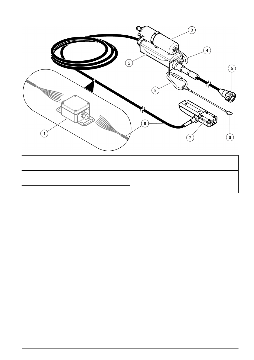
Figura 1 Sensore a immersione area/velocità
1 Scatola di giunzione (opzionale) 6 Cordone
2 Hub dell'essiccante 7 Sensore a immersione AV
3 Contenitore dell'essiccante 8 Moschettone
4 Tubo dell'aria di riferimento 9 Cavo sensore
5 Connettore
Principio di funzionamento
Il sensore funziona come un sensore area/velocità e segue l'equazione di continuità.
Portata = superficie bagnata x velocità media
Un trasduttore di pressione nel sensore converte la pressione dell'acqua in una misurazione del
livello. La misurazione del livello e la geometria del letto immessa dall'utente sono utilizzate per
calcolare la superficie bagnata del flusso.
Il sensore contiene anche due trasduttori a ultrasuoni: uno è un trasmettitore, l'altro un ricevitore.
Viene trasmesso un segnale da 1 MHz che viene riflesso dalle particelle nel flusso. Il segnale riflesso
viene ricevuto e la sua frequenza viene compensata dallo scostamento del doppler proporzionale
alla velocità delle particelle nel flusso. Il logger di portata converte lo scostamento del doppler nei
segnali a ultrasuoni di ritorno in una misurazione della velocità.
Componenti del prodotto
La Figura 2 mostra gli elementi contenuti nel pacchetto di spedizione. In caso di componenti
danneggiati o mancanti, contattare il produttore.
Italiano
67
Page 68

Figura 2 Componenti del prodotto
1 Sensore a immersione AV 3 Scatola di giunzione
2 Sensore a immersione AV con scatola di giunzione 4 Viti di montaggio (6x)
Installazione
Linee guida di installazione
P E R I C O L O
Pericolo di esplosione. I sensori AV non IS (N/P 770xx-xxx) non sono adatti per essere utilizzati in aree
classificate come pericolose. Per le aree classificate come pericolose, utilizzare sensori AV IS (N/P 880xx-xxx)
installati in conformità agli schemi di controllo inclusi nei manuali per flussometri ciechi IS 911/940.
P E R I C O L O
Pericoli potenziali in spazi confinati. Le operazioni riportate in questa sezione del manuale devono essere
eseguite esclusivamente da personale qualificato.
• Non installare più di un sensore in tubi con diametro inferiore a 61 cm (24 pollici). L'installazione di
più sensori in tubi più piccoli può creare flussi turbolenti o accelerati in prossimità dei sensori e, di
conseguenza, misurazioni imprecise.
• Montare il sensore il più vicino possibile alla parte inferiore del fondo del tubo. Questo fornisce le
misurazioni più precise per quel che riguarda il livello a bassa velocità.
• Non monitorare i flussi nel fondo del pozzetto. La migliore posizione per il sensore è 3 - 5 volte il
diametro/altezza dello scarico a monte del fondo.
• Collocare le aree di monitoraggio il più lontano possibile dai raccordi di flusso indotto, per evitare
interferenze causate da flussi combinati.
• Oggetti quali rocce, raccordi di tubi o steli valvole creano turbolenza e generano flussi ad alta
velocità in prossimità dell'oggetto. Assicurarsi che l'area dei tubi con diametro da 2 a 4 davanti
all'installazione del sensore sia priva di ostruzioni. La migliore precisione si ottiene in assenza di
interruzioni di flusso all'interno di tubi con diametro da 5 a 10.
• Non utilizzare aree con flussi a bassa velocità che creano accumuli di limo nel fondo o nel canale.
L'accumulo di limo in prossimità del sensore può ostacolare il segnale del doppler e determinare
valori del sensore e misurazioni della profondità imprecisi.
• Non utilizzare aree con flussi rapidi e profondi, dove l'installazione del sensore potrebbe rivelarsi
difficile o pericolosa.
• Non utilizzare aree con flussi ad alta velocità e poco profondi. Schizzi ed eccessiva turbolenza
attorno al sensore possono determinare dati imprecisi.
68
Italiano
Page 69

Interferenza
Il modulo interfaccia AV9000 include un ricevitore di radiofrequenze sensibile, in grado di rilevare
segnali molto piccoli. Quando collegate alle porte di comunicazione o di alimentazione ausiliaria di un
logger di portata o di un campionatore, alcune apparecchiature alimentate da corrente principale
potrebbero introdurre dei disturbi che vanno a interferire con le misurazioni della velocità del doppler.
L'interferenza nelle misurazioni è rara in aree tipiche.
Il modello AV9000 è più sensibile a disturbi che rientrano nella sua portata di analisi del doppler di
1 MHz ±13,3 kHz. Normalmente, i disturbi ad altre frequenze non causano interferenze.
Alcuni computer portatili possono causare dei problemi di interferenza quando utilizzati con adattatori
di corrente CA esterni. Se dispositivi di questo tipo interferiscono sulle misurazioni, accendere il
computer portatile utilizzando le batterie o scollegare il cavo tra il computer portatile e il logger di
flusso o il campionatore.
Installazione del modulo interfaccia AV9000
Il sensore a immersione AV viene collegato a un logger di portata serie FL o a un campionatore
AS950 mediante un modulo interfaccia AV9000. Fare riferimento a Parti di ricambio e accessori
a pagina 81 per identificare il modulo interfaccia AV9000 applicabile per il logger di portata o il
campionatore.
Nota: il sensore a immersione AV viene collegato direttamente ai flussometri Sigma per cui non è necessario
utilizzare un modulo interfaccia AV9000.
1. Installare il modulo interfaccia AV9000. Fare riferimento alla documentazione del modulo
AV9000 per le istruzioni.
2. Collegare il cavo del sensore al modulo interfaccia AV9000. Fare riferimento alla documentazione
del modulo AV9000 per le istruzioni.
3. Collegare il cavo AV9000 alla porta (o terminale) per sensore sul logger di portata o sul
campionatore. Fare riferimento alla documentazione del logger di portata o del campionatore per
le istruzioni.
Fissaggio dell'hub dell'essiccante
Fissare l'hub dell'essiccante al logger di portata o al campionatore in modo da scaricare la tensione
del cavo del sensore e del connettore. Fare riferimento alle figure dalla Figura 3 alla Figura 5.
Per ottenere le prestazioni migliori, assicurarsi di installare il contenitore dell'essiccante in verticale,
con il cappuccio rivolto verso il basso. Fare riferimento alle figure dalla Figura 3 alla Figura 5.
Figura 3 Fissaggio dell'hub dell'essiccante — Logger di portata FL900
1 Cappuccio
Italiano 69
Page 70
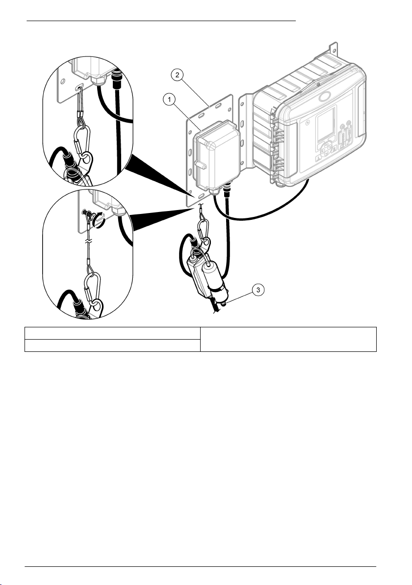
Figura 4 Fissaggio dell'hub dell'essiccante — Logger di portata FL1500
1 AV9000S con connessione a filo scoperto 3 Cappuccio
2 Piastra di montaggio accessori
70 Italiano
Page 71

Figura 5 Fissaggio dell'hub dell'essiccante — Campionatore portatile AS950
1 Cappuccio
Calibrazione del livello zero
Se almeno una delle affermazioni seguenti è corretta, procedere a una calibrazione del livello zero
prima di installare il sensore.
• La posizione di installazione è un canale in secca.
• Non è possibile stabilire un livello accurato nel flusso perché le variazioni del livello sono troppo
rapide.
• Non è possibile stabilire un livello accurato nel flusso a causa di pericoli fisici.
Nota: il sensore è calibrato in fabbrica per il range e la temperatura specificati.
Calibrazione del livello zero (logger di portata serie FL o campionatore)
Per eseguire una calibrazione del livello zero con un logger di portata FL900, effettuare tale
operazione (calibrazione dello zero in aria) con l'impostazione guidata del formato FSDATA Desktop.
Fare riferimento alla documentazione del formato FSDATA Desktop per le istruzioni. In alternativa,
eseguire una calibrazione del livello zero (calibrazione dello zero in aria) con FSDATA Desktop.
Per eseguire una calibrazione del livello zero con il logger di portata FL1500 o il campionatore, fare
riferimento alla documentazione del logger di portata FL1500 o del campionatore per le istruzioni. In
alternativa, eseguire una calibrazione del livello zero con l'impostazione guidata del formato FSDATA
Desktop con il sensore collegato a un logger di portata FL1500.
Assicurarsi che il sensore sia fuori dall'acqua e che si trovi su una superficie piana e orizzontale.
Italiano
71
Page 72

Nota: se il sensore viene sostituito, rimosso per la manutenzione o spostato su un altro strumento, eseguire una
calibrazione del livello zero.
Calibrazione del livello zero (flussometri Sigma da 910 a 950)
Effettuare una calibrazione del livello zero nel modo seguente:
Nota: se il sensore viene sostituito, rimosso per la manutenzione o spostato su un altro strumento, eseguire di
nuovo una calibrazione del livello zero.
1. Collegare il flussometro a un computer dotato di software InSight. Fare riferimento alla
documentazione del flussometro per le istruzioni.
2. Avviare il software InSight sul computer.
3. Selezionare Remote Programming (Programmazione remota).
4. Dall'elenco Real Time Operations (Operazioni in tempo reale), selezionare il sensore di livello.
5. Rimuovere la sonda dal liquido e posizionare la parte piatta del sensore sul ripiano o sul
pavimento con il sensore (la piastra con i fori) rivolto verso il basso.
6. Completata l'operazione, premere OK sulla finestra di dialogo.
Fissaggio del sensore alla staffa di montaggio
Le staffe di montaggio sono dotate di fori pre-trapanati per il montaggio diretto del sensore sulla
staffa. Per montare il sensore sulla staffa di montaggio, fare riferimento alla figura e attenersi ai
relativi passaggi.
Nota: se il sensore è di tipo a bagno d'olio, accertarsi che sia riempito di olio prima di montarlo sulla staffa di
montaggio. Fare riferimento alla sezione relativa al rabbocco dell'olio per sensori in questo manuale.
1. Fissare il sensore all'anello elastico (Figura 6). Montare il sensore in modo da estendere il
trasduttore di pressione oltre il bordo dell'anello.
2. Disporre il cavo lungo il bordo della staffa (Figura 6).
3. Utilizzare dei serracavi in nylon per fissare il cavo alla staffa di montaggio.
Il cavo deve uscire dall'area legata sul o in prossimità del lato superiore del tubo.
Nota: se è presente una grande quantità di limo sulla parte inferiore del tubo, ruotare la staffa fino ad
allontanare il sensore dal limo (Figura 8 a pagina 75). Assicurarsi che il sensore rimanga sempre al di sotto
del livello di acqua minimo previsto. Il limo deve essere misurato di frequente ma non deve essere smosso.
72
Italiano
Page 73

Figura 6 Fissaggio del sensore alla staffa di montaggio
1 Sensore 3 Cavo sensore
2 Anello elastico 4 Viti (2)
Posizionamento del sensore e della staffa di montaggio nel tubo
1. Posizionare il sensore nel flusso. La Figura 7 mostra una configurazione a monte standard, una
configurazione a valle standard e una configurazione riservata al sensore a valle.
Per determinare più facilmente la configurazione ottimale, fare riferimento a Tabella 1. Per
ulteriori informazioni sulle configurazioni, fare riferimento al manuale del logger appropriato.
2. Far scorrere la staffa di montaggio il più possibile all'interno del tubo per prevenire effetti di
abbassamento in prossimità dell'estremità del tubo.
3. Posizionare il sensore nel punto più basso del canale. In presenza di una quantità eccessiva di
limo sulla parte inferiore del tubo, ruotare la staffa nel tubo fino ad allontanare il sensore dal limo.
Fare riferimento alla Figura 8.
Italiano
73
Page 74

Figura 7 Posizioni sensore
1 A monte, rivolto verso il flusso 2 A valle, rivolto verso il flusso 3 A valle, invertito
Tabella 1 Selezione della direzione della sonda
Opzione Descrizione
A monte Consigliata per la maggior parte delle applicazioni. Il flusso sul sensore deve essere il più
A valle Utilizzare questa opzione quando il sensore è installato a valle del punto di misurazione (nel
A valle (sensore
invertito)
lineare possibile senza cali o variazioni sul punto di misurazione.
Montare il sensore nel tubo con il bordo smussato rivolto verso il flusso nel punto in cui il flusso
entra nell'area di misurazione.
punto in cui il flusso esce dall'area). Questa opzione è utile nel caso di ingresso di più flussi in
un'area e tutti i flussi combinati in uno vengono misurati in un unico punto di uscita. Questa
opzione può essere utilizzata anche in caso di impianti idraulici che impediscono il montaggio
del sensore in un'area a monte.
Montare il sensore rivolto verso il flusso.
Utilizzare questa opzione in caso di mancato funzionamento dell'opzione B a causa di
un'uniformità di flusso insufficiente nel sotterraneo. Il valore massimo della velocità in questo
tipo di installazione è 5 fps quando non si utilizza il modulo interfaccia AV9000. Montare il
sensore nella direzione a valle. Il produttore consiglia di verificare la velocità delineando il
flusso e utilizzando un moltiplicatore di velocità dell'area, se necessario, per ottenere un valore
più preciso.
Nota: quando il logger FL900 è utilizzato insieme al modulo interfaccia AV9000 e al sensore a immersione AV,
l'utente ha la possibilità di selezionare l'opzione Reversed Sensor (Sensore invertito) nel menu Sensor Port
Set Up (Impostazione porta sensore).
74 Italiano
Page 75
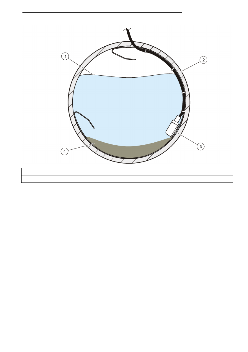
Figura 8 Come tenere lontano il limo durante il montaggio del sensore
1 Acqua 3 Sensore
2 Tubo 4 Limo
Funzionamento
Per i sensori collegati a un logger di portata FL900, collegare un computer dotato di software
FSDATA Desktop al logger di portata per eseguire la configurazione, la calibrazione e la raccolta dei
dati dei sensori. Fare riferimento alla documentazione del software FSDATA Desktop per eseguire la
configurazione, la calibrazione e la raccolta dei dati dei sensori.
Per i sensori collegati a un logger di portata FL1500, fare riferimento alla documentazione del logger
di portata FL1500 per eseguire la configurazione, la calibrazione e la raccolta dei dati dei sensori. In
alternativa, collegare un computer dotato di software FSDATA Desktop al logger di portata per
eseguire la configurazione, la calibrazione e la raccolta dei dati dei sensori. Fare riferimento alla
documentazione del software FSDATA Desktop per eseguire la configurazione, la calibrazione e la
raccolta dei dati dei sensori.
Per i sensori collegati a un campionatore AS950, fare riferimento alla documentazione del
campionatore AS950 per eseguire la configurazione, la calibrazione e la raccolta dei dati dei sensori.
Per i sensori collegati a un flussometro Sigma 910, 911, 920, 930 o 940, collegare un computer
dotato di software InSight al flussometro Sigma per eseguire la configurazione, la calibrazione e la
raccolta dei dati dei sensori.
Installazione del software
Assicurarsi che sul computer sia installata la versione più recente del software FSDATA Desktop o
InSight, secondo necessità. Scaricare il software da http://www.hachflow.com. Fare clic su Support,
quindi selezionare Software Downloads.
Italiano
75
Page 76

Configurazione del sensore
I sensori collegati a un logger di portata FL900 devono essere configurati con l'impostazione guidata
del formato FSDATA Desktop. Fare riferimento alla documentazione del formato FSDATA Desktop
per le istruzioni.
Per i sensori collegati a un logger di portata FL1500 o a un campionatore AS950, fare riferimento alla
documentazione del logger di portata FL1500 o del campionatore per configurarli. In alternativa,
configurare i sensori con l'impostazione guidata del formato FSDATA quando i sensori sono collegati
a un logger di portata FL1500.
Per i sensori collegati a un flussometro Sigma, eseguire le operazioni indicate in Calibrazione del
livello per flussometri Sigma a pagina 76.
Nota: se un sensore viene sostituito, rimosso per la manutenzione o spostato su un altro strumento, eseguire una
calibrazione del livello.
Calibrazione del livello per flussometri Sigma
1. Con il sensore immerso nel flusso, monitorare lo stato della corrente con un PC dotato di
software Insight o con il display di un flussometro.
2. Misurare fisicamente la distanza dalla parte superiore del tubo alla superficie dell'acqua. Fare
riferimento alla Figura 9.
3. Sottrarre il numero ottenuto al passaggio 2 dal diametro del tubo. Fare riferimento alla Figura 9.
Il risultato è la profondità dell'acqua. Fare riferimento alla Figura 9.
4. Utilizzare la funzione Adjust Level (Regolazione del livello) del software per immettere la
profondità dell'acqua misurata fisicamente.
Figura 9 Misurazione del livello dell'acqua
1 Livello dell'acqua
76 Italiano
Page 77

Manutenzione
A T T EN Z I O N E
Pericoli multipli. Gli interventi descritti in questa sezione del documento devono essere eseguiti solo da
personale qualificato.
Pulizia del sensore
Pulire la porta del trasduttore in caso di:
• Aumento o diminuzione imprevista del flusso o dei trend di livello
• Dati di livello mancanti o errati con dati di velocità validi
• Depositi eccessivi di limo tra il trasduttore e le coperture protettive
Note
• Non toccare il trasduttore del sensore poiché ciò potrebbe causare danni e compromettere il
funzionamento del sensore.
• Utilizzare solo soluzioni detergenti approvate, elencate nella Tabella 2. Non utilizzare alcun tipo di
spazzola o panno per pulire il trasduttore di pressione poiché ciò potrebbe causare danni o
compromettere il funzionamento del sensore. In presenza di detriti, irrorare la membrana con
acqua e utilizzare una punta a Q per rimuovere delicatamente l'accumulo.
• Se la guarnizione manca o è danneggiata, installarne una nuova. Una guarnizione danneggiata o
mancante determina valori non accurati.
• Dopo aver pulito il sensore, pulire la guarnizione e la copertura protettiva prima dell'installazione.
• Dopo aver pulito un sensore a bagno d'olio, rabboccare con olio per sensori.
• Se un sensore non viene utilizzato per un lungo periodo, non conservarlo su uno scaffale asciutto.
Il produttore consiglia di conservare il sensore con la relativa testina in un secchio d'acqua, per
evitare che i residui di olio creino incrostazioni nel canale del trasduttore di pressione.
Per pulire il sensore:
1. Immergere il sensore in acqua e sapone.
2. Rimuovere le viti dalla copertura protettiva. Fare riferimento alla Figura 10.
3. Rimuovere la copertura e la guarnizione. Fare riferimento alla Figura 10.
4. Ruotare delicatamente il sensore in una soluzione detergente appropriata per rimuovere il limo.
Utilizzare uno flacone dosatore o a spray per eliminare i depositi più pesanti.
5. Pulire la guarnizione e la copertura.
6. Fissare la guarnizione e la copertura. Serrare le viti finché la guarnizione non inizia a
comprimersi.
Italiano
77
Page 78

Figura 10 Copertura protettiva del sensore e guarnizione
1 Coperchio protettivo 2 Guarnizione 3 Sensore
Tabella 2 Soluzioni di lavaggio accettabili e inaccettabili
Accettabile Non toccare.
Detergente per piatti e acqua Candeggina concentrata
Lavavetri Cherosene
Alcol isopropilico Benzina
Acidi diluiti Idrocarburi aromatici
Sostituzione dell'essiccante
A V V I S O
Non azionare il sensore senza granuli di essiccante o con granuli diventati verdi. Il sensore potrebbe danneggiarsi
irrimediabilmente.
Sostituire subito i granuli di essiccante quando iniziano ad assumere una colorazione verde. Fare
riferimento alla Figura 11.
Nota: per introdurre l'essiccante nuovo non è necessario rimuovere il contenitore dell'essiccante dall'hub.
Nel punto 5 della Figura 11, controllare che l'O-ring sia pulito e privo di sporcizia o detriti. Esaminare
l'O-ring per ricercare eventuali spaccature, vaiolature o segni di danni. Sostituire l'O-ring se
danneggiato. Per facilitare il montaggio, applicare del grasso agli O-ring disidratati o nuovi; questa
operazione migliora la tenuta degli O-ring e ne aumenta la vite utile.
Per ottenere le prestazioni migliori, assicurarsi di installare il contenitore dell'essiccante in verticale,
con il cappuccio rivolto verso il basso. Fare riferimento alla Fissaggio dell'hub dell'essiccante
a pagina 69.
Nota: Quando i cordoni iniziano a diventare verdi si possono rigenerare con il calore. Rimuovere i cordoni dalla
bomboletta e scaldarli a 100-180 ºC (212-350 ºF) finché non diventano arancioni. Non scaldare la bomboletta. Se i
granuli non diventano arancioni, sostituirli con essiccante nuovo.
78
Italiano
Page 79

Figura 11 Sostituzione dell'essiccante
Sostituire la membrana idrofobica
Sostituire la membrana idrofobica in caso di:
• Aumento o diminuzione imprevista dei trend di livello.
• Dati di livello mancanti o errati con dati di velocità validi.
• Membrana lacerata o saturata con acqua o grasso.
Per la sostituzione della membrana, fare riferimento ai passaggi illustrati di seguito. Al passaggio 4,
controllare che si verifichi quanto segue:
• La parte liscia della membrana idrofobica deve trovarsi sulla superficie interna del contenitore
dell'essiccante.
• La membrana idrofobica deve piegarsi e inserirsi a fondo nella filettatura fino a non essere più
visibile.
• La membrana idrofobica deve ruotare con il nipplo quando il nipplo nel contenitore dell'essiccante
ruota. Se la membrana non ruota, è danneggiata. Eseguire nuovamente la procedura utilizzando
una nuova membrana.
Per ottenere le prestazioni migliori, assicurarsi di installare il contenitore dell'essiccante in verticale,
con il cappuccio rivolto verso il basso. Fare riferimento a Fissaggio dell'hub dell'essiccante
a pagina 69.
Italiano
79
Page 80

80 Italiano
Page 81
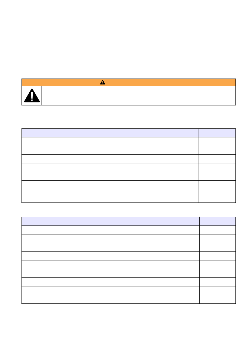
Rabbocco dell'olio nel sensore
Ispezionare l'olio nel sensore per verificare che non ci siano bolle d'aria di grandi dimensioni durante
gli interventi di manutenzione programmati dal cliente. Bolle di grandi dimensioni possono ridurre le
proprietà anti-incrostazione dell'olio. Bolle di piccole dimensioni (< ¼ di pollice di diametro) non
influiscono sulle proprietà dell'olio.
Per il rabbocco con olio per sensori, fare riferimento alla documentazione inclusa nel kit per il
rabbocco dell'olio siliconico. Fare riferimento a Parti di ricambio e accessori a pagina 81 per
informazioni sull'ordine.
Parti di ricambio e accessori
A V V E R T E N Z A
Pericolo di lesioni personali. L'uso di parti non approvate può causare lesioni personali, danni alla
strumentazione o malfunzionamenti dell'apparecchiatura. La parti di ricambio riportate in questa
sezione sono approvate dal produttore.
Nota: Numeri di Prodotti e Articoli possono variare per alcune regioni di vendita. Contattare il distributore
appropriato o fare riferimento al sito Web dell'azienda per dati di contatto.
Parti di ricambio
Descrizione Codice prodotto
Granuli di essiccante, contenitore da 1,5 libbre 8755500
Contenitore dell'essiccante 8542000
Membrana idrofobica 3390
O-ring, cappuccio del contenitore dell'essiccante, DI 1,176 x DE 0,070 5252
Olio siliconico, include due confezioni di olio da 50 ml per rabboccare 100 sensori 7724700
Il kit per il rabbocco dell'olio siliconico include:
erogatore, due confezioni di olio da 50 ml, foglio d'istruzioni e materiale di montaggio vario
Hub dell'essiccante
1
7724800
7722800
Accessori
Descrizione Codice prodotto
Modulo interfaccia AV9000, logger di portata FL900 8531300
Modulo interfaccia AV9000S con connessione a filo scoperto, logger di portata FL1500 9504601
Modulo interfaccia AV9000S, campionatori portatili AS950 9504600
Piastra di montaggio accessori, logger di portata FL1500 8309300
Cavo personalizzato, da sensore a scatola di giunzione, 0,3 - 30 m (1 - 99 piedi) 77155-PRB
Cavo personalizzato, da scatola di giunzione a hub dell'essiccante, 0,3 - 30 m (1 - 99 piedi) 77155-HUB
Kit gel in ceramica di silicone per scatola di giunzione 7725600
Gel per il rabbocco, ceramica di silicone
Pistola per il rabbocco del gel
3
2
7729800
7715300
1
Utilizzare il numero di parte 77155-HUB per selezionare la lunghezza del cavo a valle dell'hub
dell'essiccante.
2
Ordinare tre kit per riempire una singola scatola di giunzione.
3
Utilizzabile anche come pistola per il rabbocco dell'olio siliconico
Italiano 81
Page 82

Descrizione Codice prodotto
Kit retrofit per trasformare un sensore con una piastra di copertura non a bagno d'olio in un
7730000
sensore con una piastra di copertura a bagno d'olio, include 7724800
Attrezzo di inserimento per l'installazione di anelli di montaggio a livello stradale 9574
Anello di montaggio per tubo con ∅ 15,24 cm (6 poll.)
Anello di montaggio per tubo con ∅ 20,32 cm (8 poll.)
Anello di montaggio per tubo con ∅ 25,40 cm (10 poll.)
Anello di montaggio per tubo con ∅ 30,48 cm (12 poll.)
Anello di montaggio per tubo con ∅ 38,10 cm (15 poll.)
Anello di montaggio per tubo con ∅ 45,72 cm (18 poll.)
Anello di montaggio per tubo con ∅ 50,8 - 53,34 cm (20 - 21 poll.)
Anello di montaggio per tubo con ∅ 61 cm (24 poll.)
4
4
4
5
5
5
5
5
1361
1362
1363
1364
1365
1366
1353
1370
Tabella di selezione staffe di montaggio
Diametro tubo Selezione staffa di montaggio
Codice prodotto
1473 -- 6,25"
(15,85 cm) di
lunghezza, consente
di aggiungere 2"
(5,08 cm) al
diametro della staffa
Codice prodotto
1525 -- 9,5"
(24,13 cm) di
lunghezza, consente
di aggiungere 3"
(7,62 cm) al
diametro della staffa
Codice prodotto
1759 -- 19,"
(48,26 cm) di
lunghezza, consente
di aggiungere 6"
(15,24 cm) al
diametro della staffa
8" (20,32 cm) 0 0 1 0
10" (25,4 cm) 1 0 1 0
12" (30,48 cm) 0 1 1 0
15" (38,1 cm) 0 2 1 0
18" (45,72 cm) 0 1 2 0
21" (53,34 cm) 0 2 2 0
24" (60,96 cm) 0 1 3 0
27" (68,58 cm) 1 0 1 1
30" (76,2 cm) 1 1 1 1
33" (83,2 cm) 1 0 2 1
36" (91,44 cm) 1 1 2 1
42" (1,06 m) 1 1 3 1
45" (1,14 m) 1 1 1 2
48" (1,21 m) 1 0 2 2
6
Codice prodotto
1318 -- 50,25"
(127 cm) di
lunghezza, consente
di aggiungere 16"
(40,64 cm) al
diametro della staffa
4
Richiede il codice articolo 3263
5
Il sensore viene montato direttamente su staffa.
6
Oltre ai segmenti di staffa mostrati di seguito, un complessivo staffa di fissaggio richiede dei
fermi di montaggio per il sensore AV (3263) e un complessivo jack a forbice (3719).
82 Italiano
Page 83

Inhaltsverzeichnis
Technische Daten auf Seite 83 Betrieb auf Seite 95
Allgemeine Informationen auf Seite 84 Wartung auf Seite 97
Installation auf Seite 88 Ersatzteile und Zubehör auf Seite 101
Technische Daten
Änderungen vorbehalten.
Technische Daten – Eintauch-Flächengeschwindigkeitssensor
Die Leistung variiert je nach Kanalgröße, Kanalform und Standortbedingungen.
Geschwindigkeitsmessung
Methode Dopplerultraschall
Sensortyp: Zwei piezoelektrische Kristalle, je 1 MHz
Typische Mindesttiefe für
Geschwindigkeit
Messbereich -1,52 bis 6,10 m/s (-5 bis 20 Fuß/s)
Genauigkeit ± 2 % der Messung (in Wasser mit gleichförmigem
Tiefenmessung
Methode Druckwandler mit Edelstahlmembran
Genauigkeit (statisch)
2 cm (0.8")
Geschwindigkeitsprofil)
• ±0,16 % des vollständigen Messbereichs, ±1,5 % der Messung bei
konstanter Temperatur (±2,5 ºC)
• ±0,20 % des vollständigen Messbereichs, ±1,75 % der Messung bei
0 bis 30 ºC (32 bis 86 ºF)
• ±0,25 % des vollständigen Messbereichs, ±2,1 % der Messung bei
0 bis 70 ºC (32 bis 158 ºF)
Fehler durch
geschwindigkeitsinduzierte Tiefe
Tiefenbereich
Zulässige Tiefe
Allgemeine Attribute
Lufteinlass Atmosphärische Druckreferenz durch Trocknungsmittel geschützt
Betriebstemperatur 0 bis 70 ºC (32 bis 158 ºF)
Tiefenkompensierter
Temperaturbereich
Werkstoffe Außengehäuse aus Noryl® mit Epoxidharzverguss innen
Leistungsaufnahme 1,2 W bei 12 V Gleichstrom oder weniger
Kabel Urethan-Sensorkabel mit Belüftung
Kompensiert auf Basis der Durchflussgeschwindigkeit
• Standard: 0–3 m (0–10 Fuß)
• Erweitert: 0–9 m (0–30 Fuß)
• Standard: 10,5 m (34,5 Fuß)
• Erweitert: 31,5 m (103,5 Fuß)
0 bis 70 ºC (32 bis 158 ºF)
Deutsch 83
Page 84

Stecker hartanodisiert, erfüllt militärische Spezifikation 5015
Erhältliche Kabellängen
Kabeldurchmesser 0.91 cm (0.36")
Abmessungen 2,3 cm H x 3,8 cm B x 13,5 cm T (0,9 Zoll H x 1,5 Zoll B x 5,31 Zoll T)
Kompatible Instrumente Sigma 910, 920, 930, 930 T, 950, 900 Max Probenehmer und die
• Standard: 9, 15, 23 und 30,5 m (30, 50, 75, 100 Fuß)
• Kundenspezifisch: 30,75 m (101 Fuß) bis höchstens 76 m (250 Fuß)
AV9000 Schnittstellenmodule für Durchfluss-Logger der FL Serie und
AS950 Probenehmer
Technische Daten – AV9000 Schnittstellenmodul
Geschwindigkeitsmessung
Messverfahren 1 MHz Dopplerultraschall
Doppleranalysetyp Digitale Spektralanalyse
-1,52 bis 6,10 m/s (-5 bis 20 Fuß/s)
± 2 % der Messung oder 0,015 m/s (0,05 fps) (gleichförmiges
Geschwindigkeitsprofil, bekannte Salinität, positiver Durchfluss.
Leistung vor Ort ist standortspezifisch.)
Dopplergenauigkeit ±1 % der Messung oder 0,0076 m/s (0,025 fps) (mit elektronisch
Stromversorgung
Versorgungsspannung 9-15 V Gleichspannung
Höchststrom < 130 mA bei 12 V DC bei dem Eintauch-
Energie pro Messung <15 Joule (typisch)
Betriebstemperatur
-18 bis 60 ºC (0 bis 140 ºF) bei 95 %
relativer Luftfeuchtigkeit
Gehäuse
Größe (B x H x T) AV9000: 13 x 17,5 x 5 cm (5,0 x 6,875 x 2,0 Zoll)
Umweltverträglichkeit NEMA 6P, IP 68
Gehäusematerial PC/ABS
simuliertem Dopplersignal, -7,62 bis +7,62 m/s (-25 bis +25 fps)
Geschwindigkeit von gleichem Wert. Siehe Konfigurieren des Sensors
auf Seite 96.
Flächengeschwindigkeitssensor
AV9000S: 12,01 x 14,27 x 6,86 cm (4,73 x 5,62 x 2,70 Zoll)
Allgemeine Informationen
Der Hersteller ist nicht verantwortlich für direkte, indirekte, versehentliche oder Folgeschäden, die
aus Fehlern oder Unterlassungen in diesem Handbuch entstanden. Der Hersteller behält sich
jederzeit und ohne vorherige Ankündigung oder Verpflichtung das Recht auf Verbesserungen an
diesem Handbuch und den hierin beschriebenen Produkten vor. Überarbeitete Ausgaben der
Bedienungsanleitung sind auf der Hersteller-Webseite erhältlich.
84
Deutsch
Page 85

Sicherheitshinweise
H I N W E I S
Der Hersteller ist nicht für Schäden verantwortlich, die durch Fehlanwendung oder Missbrauch dieses Produkts
entstehen, einschließlich, aber ohne Beschränkung auf direkte, zufällige oder Folgeschäden, und lehnt jegliche
Haftung im gesetzlich zulässigen Umfang ab. Der Benutzer ist selbst dafür verantwortlich, schwerwiegende
Anwendungsrisiken zu erkennen und erforderliche Maßnahmen durchzuführen, um die Prozesse im Fall von
möglichen Gerätefehlern zu schützen.
Bitte lesen Sie dieses Handbuch komplett durch, bevor Sie dieses Gerät auspacken, aufstellen oder
bedienen. Beachten Sie alle Gefahren- und Warnhinweise. Nichtbeachtung kann zu schweren
Verletzungen des Bedieners oder Schäden am Gerät führen.
Stellen Sie sicher, dass die durch dieses Messgerät bereitgestellte Sicherheit nicht beeinträchtigt
wird. Verwenden bzw. installieren Sie das Messsystem nur wie in diesem Handbuch beschrieben.
Bedeutung von Gefahrenhinweisen
Kennzeichnet eine mögliche oder drohende Gefahrensituation, die, wenn sie nicht vermieden wird, zum Tod oder
zu schweren Verletzungen führt.
Kennzeichnet eine mögliche oder drohende Gefahrensituation, die, wenn sie nicht vermieden wird, zum Tod oder
zu schweren Verletzungen führen kann.
Kennzeichnet eine mögliche Gefahrensituation, die zu geringeren oder moderaten Verletzungen führen kann.
Kennzeichnet eine Situation, die, wenn sie nicht vermieden wird, das Gerät beschädigen kann. Informationen, die
besonders beachtet werden müssen.
Warnhinweise
Lesen Sie alle am Gerät angebrachten Aufkleber und Hinweise. Nichtbeachtung kann Verletzungen
oder Beschädigungen des Geräts zur Folge haben. Im Handbuch werden auf die am Gerät
angebrachten Symbole in Form von Warnhinweisen verwiesen.
Dies ist das Sicherheits-Warnsymbol. Befolgen Sie alle Sicherheitshinweise im Zusammenhang mit
diesem Symbol, um Verletzungen zu vermeiden. Wenn es am Gerät angebracht ist, beachten Sie die
Betriebs- oder Sicherheitsinformationen im Handbuch.
G E F A H R
W A R N U N G
V O R S I C H T
H I N W E I S
Dieses Symbol zeigt das Vorhandensein von Geräten an, die empfindlich auf elektrostatische
Entladung reagieren. Es müssen Vorsichtsmaßnahmen getroffen werden, um die Geräte nicht zu
beschädigen.
Elektrogeräte, die mit diesem Symbol gekennzeichnet sind, dürfen nicht im normalen öffentlichen
Abfallsystem entsorgt werden. Senden Sie Altgeräte an den Hersteller zurück. Dieser entsorgt die
Geräte ohne Kosten für den Benutzer.
Vorsichtsmaßnahmen in geschlossenen Räumen
G E F A H R
Explosionsgefahr. Personen, die in begrenzten Räume arbeiten, müssen zuvor in Verfahren bezüglich
Betreten, Belüftung und Zugang, Evakuierungs-/Rettungsverfahren und sicherer Arbeitspraxis geschult
worden sein.
Deutsch 85
Page 86

Die nachfolgenden Informationen sollen Benutzern helfen, die Gefahren und Risiken beim Betreten
geschlossener Räume zu verstehen.
Am 15. April 1993 wurde die endgültige Entscheidung von der OSHA (Occupational Safety and
Health Administration) zu der Regelung CFR 1910.146, Permit Required Confined Spaces
(Erforderliche Erlaubnis für geschlossene Räume), als Gesetz erlassen. Dieser Standard im Sinne
des Schutzes der Gesundheit und der Sicherheit für Arbeiter in geschlossenen Räumen betrifft mehr
als 250.000 Industriestandorte in den USA.
Definition eines geschlossenen Raums:
Ein geschlossener Raum ist ein Ort oder eine umschlossene Räumlichkeit, bei der eine oder
mehrere der folgenden Bedingungen erfüllt sind bzw. die unmittelbare Möglichkeit besteht, dass eine
oder mehrere Bedingungen erfüllt werden könnten:
• Eine Atmosphäre mit einer Sauerstoffkonzentration von weniger als 19,5 % oder mehr als 23,5 %
und/oder einer Schwefelwasserstoff (H2S)-Konzentration von mehr als 10 ppm.
• Eine Atmosphäre, die durch das Vorkommen von Gasen, Dämpfen, Nebel, Staub oder Fasern
leicht entzündlich oder explosiv sein könnte.
• Toxische Materialien, die durch körperlichen Kontakt oder durch Einatmen zu Verletzungen, zur
Schädigung der Gesundheit oder zum Tod führen können.
Geschlossene Räume sind nicht geeignet für den Aufenthalt von Menschen. Geschlossene Räume
unterliegen der Zugangsbeschränkung und enthalten bekannte oder potenzielle Gefahren. Beispiele
für geschlossene Räume sind Kanalschächte, Schornsteine, Rohre, Fässer, Schaltschränke und
andere ähnliche Orte.
Vor dem Betreten solcher geschlossener Räume und/oder Orte, an denen gefährliche Gase,
Dämpfe, Nebel, Staub oder Fasern vorhanden sein können, müssen immer alle
Standardsicherheitsmaßnahmen beachtet werden. Vor dem Betreten eines geschlossenen Raums
müssen alle Verfahren im Bezug auf das Betreten von geschlossenen Räumen in Ermittlung
gebracht und gelesen werden.
Produktübersicht
Der Eintauch-Flächengeschwindigkeits- (AV-) Sensor wird mit Sigma Durchflussmessgeräten,
Durchfluss-Loggern der FL Serie und AS950 Probenehmern verwendet, um die Durchflussrate in
offenen Kanälen zu messen. Siehe Abbildung 1.
Der Sensor ist in ölgefüllten und nicht mit Öl gefüllten Versionen erhältlich. Der Sensor ohne Öl wird
für durchwegs saubere Medien oder solche Einsatzorte, an denen das Rohr trockenlaufen kann,
verwendet. Der ölgefüllte Sensor ist für Standorte mit einem hohen Maß an biologischem Wachstum,
Kies oder Schlick ausgelegt.
Hinweis: Verwenden Sie einen ölgefüllten Sensor nicht in einem Rohr, das abtrocknen kann.
Die Verbindung des Eintauch-AV-Sensors mit einem Durchfluss-Logger der FL Serie bzw. mit einem
AS950 Probenehmer erfolgt über ein AV9000 Schnittstellenmodul. Sie finden das geeignete
AV9000 Modell für den Durchfluss-Logger bzw. den Probenehmer in Ersatzteile und Zubehör
auf Seite 101.
Hinweis: Der Eintauch-AV-Sensor wird direkt an Sigma Durchflussmessgeräte angeschlossen. Ein
AV9000 Schnittstellenmodul wird nicht benötigt.
86
Deutsch
Page 87

Abbildung 1 Eintauch-Flächengeschwindigkeitssensor
1 Anschlussdose (optional) 6 Band
2 Trocknungsmittel-Anschlussdose 7 Eintauch-AV-Sensor
3 Trocknungsmittelbehälter 8 Karabinerhaken
4 Luftreferenzschlauch 9 Sensorkabel
5 Stecker
Funktionsweise
Der Sensor arbeitet als Flächengeschwindigkeitssensor, und zwar nach der Kontinuitätsgleichung:
Durchflussrate = benetzte Fläche x mittlere Geschwindigkeit
Mit einem Druckwandler im Sensor wird der Druck des Wassers in eine Höhenmessung
umgewandelt. Anhand der Tiefenmessung und der vom Benutzer eingegebenen Kanalgeometrie
wird die vom Mediumfluss benetzte Fläche berechnet.
Der Sensor enthält außerdem zwei Ultraschallwandler: Der eine dient als Sender und der andere als
Empfänger. Es wird ein Signal von 1 MHz ausgesendet, das von den Partikeln im Massenstrom
reflektiert wird. Das reflektierte Signal wird empfangen, und seine Frequenz wird durch die DopplerVerschiebung, die zu der Geschwindigkeit der Partikel im Massenstrom proportional ist, verschoben.
Mit dem Durchfluss-Logger wird die Doppler-Verschiebung in den zurückgegebenen
Ultraschallsignalen in eine Geschwindigkeitsmessung umgewandelt.
Produktkomponenten
In Abbildung 2 sind die Elemente im Lieferumfang dargestellt. Wenden Sie sich an den Hersteller,
wenn Komponenten beschädigt sind oder fehlen.
Deutsch
87
Page 88

Abbildung 2 Produktkomponenten
1 Eintauch-AV-Sensor 3 Anschlussdose
2 Eintauch-AV-Sensor mit Anschlussdose 4 Befestigungsschrauben (6 x)
Installation
Installationsanleitung
G E F A H R
Explosionsgefahr. Die nicht-IS AV Sensoren (770xx-xxx P/Ns) sind nicht für die Verwendung an klassifizierten
explosionsgefährdeten Standorten ausgelegt. Verwenden Sie für klassifizierte explosionsgefährdete Standorte IS
AV Sensoren (880xx-xxx PNs), die anhand der Kontrollzeichnungen in den Handbüchern zu den 911/940 IS
Blind-Durchflussmessern angebracht wurden.
G E F A H R
Potenzielle Gefahren in geschlossenen Räumen. Nur qualifiziertes Personal sollte die in diesem Kapitel der
Bedienungsanleitung beschriebenen Aufgaben durchführen.
• Bringen Sie in Rohren mit einem Durchmesser von weniger als 61 cm (24 Zoll) nicht mehr als
einen Sensor an. Mehrere Sensoren in kleineren Rohren können in der Nähe der Sensoren
turbulente oder beschleunigte Durchflüsse erzeugen, die wiederum zu ungenauen Messungen
führen.
• Befestigen Sie den Sensor so nah wie möglich an der Rohrsohle. Dadurch erhalten Sie die
genauesten Messungen bei geringer Geschwindigkeit.
• Überwachen Sie nicht den Durchfluss direkt an den Rohrsohlen von Kontrollschächten. Der beste
Standort für den Sensor ist der drei- bis fünffache Durchmesser (bzw. die Höhe) des
Abflusskanals stromaufwärts von Kontrollschächten.
• Platzieren Sie Überwachungsstandorte so weit wie möglich von zuführenden Abzweigungen
entfernt, um Störungen durch Turbulenzen zu vermeiden.
• Objekte wie Steine, Rohrverbindungen oder Ventilschäfte erzeugen Turbulenzen und generieren
Durchflüsse mit hoher Geschwindigkeit in der Nähe des Objekts. Vergewissern Sie sich, dass der
Bereich vom zwei- bis vierfachen Rohrdurchmesser vor dem Befestigungspunkt des Sensors frei
ist von Hindernissen. Größte Genauigkeit erhalten Sie, wenn es innerhalb des fünf- bis
zehnfachen Rohrdurchmessers keine Störungen im Durchfluss gibt.
• Nutzen Sie keine Standorte mit Durchflüssen geringer Geschwindigkeit, an denen
Schlickansammlungen an der Rohrsohle oder im Kanal entstehen. Schlickansammlungen in der
Nähe des Sensors können das Dopplersignal blockieren und ungenaue Sensor- und
Höhenmessungen verursachen.
• Nutzen Sie keine Standorte mit tiefen und schnellen Durchflüssen, an denen die Befestigung des
Sensors schwierig oder gefährlich wäre.
88
Deutsch
Page 89

• Nutzen Sie keine Standorte mit schnellen Durchflüssen von geringer Tiefe. Überschwappen und
übermäßige Turbulenzen um den Sensor herum können zu ungenauen Daten führen.
Störeinfluss
Das AV9000 Schnittstellenmodul enthält einen empfindlichen Hochfrequenzempfänger, der sehr
schwache Signale empfangen kann. Einige netzbetriebene Geräte können bei Verbindung mit dem
Übertragungs- oder Hilfs-Netzanschluss eines Durchfluss-Loggers oder Probenehmers
Elektrorauschen verursachen, das die Doppler-Geschwindigkeitsmessung stört. Störungen der
Messungen sind an typischen Standorten selten.
Der AV9000 ist am empfänglichsten für Störungen, die in seinem Doppler-Analysebereich zwischen
1 MHz ±13,3 kHz liegen. Elektrorauschen mit anderen Frequenzen führt in der Regel nicht zu
Störungen.
Einige Laptops können Störungen verursachen, wenn sie mit einem externen Netzadapter betrieben
werden. Falls die Messungen durch ein solches Gerät beeinflusst werden, verwenden Sie den
Laptop im Batteriebetrieb oder trennen Sie das Kabel zwischen dem Laptop und dem DurchflussLogger bzw. dem Probenehmer.
Installation des AV9000 Schnittstellenmoduls
Die Verbindung des Eintauch-AV-Sensors mit einem Durchfluss-Logger der FL Serie bzw. mit einem
AS950 Probenehmer erfolgt über ein AV9000 Schnittstellenmodul. Sie finden das geeignete
AV9000 Schnittstellenmodul für den Durchfluss-Logger bzw. den Probenehmer in Ersatzteile und
Zubehör auf Seite 101.
Hinweis: Der Eintauch-AV-Sensor wird direkt an Sigma Durchflussmessgeräte angeschlossen. Ein
AV9000 Schnittstellenmodul wird nicht benötigt.
1. Installieren Sie das AV9000 Schnittstellenmodul. Anleitungen finden Sie in der Dokumentation
zum AV9000.
2. Verbinden Sie das Sensorkabel mit dem AV9000 Schnittstellenmodul. Anleitungen finden Sie in
der Dokumentation zum AV9000.
3. Verbinden Sie das Kabel des AV9000 mit einem Sensoranschluss (oder einer Klemme) am
Durchfluss-Logger bzw. am Probenehmer. Anleitungen finden Sie in der Dokumentation zum
Durchfluss-Logger bzw. zum Probenehmer.
Anbringen der Trocknungsmittel-Anschlussdose
Befestigen Sie die Trocknungsmittel-Anschlussdose am Durchfluss-Logger oder am Probenehmer,
um dem Sensorkabel und dem Stecker Zugentlastung zu geben. Siehe Abbildung 3 oder
Abbildung 5.
Achten Sie darauf, dass Sie den Trocknungsmittelbehälter vertikal mit der Verschlusskappe nach
unten installieren, damit die beste Leistung erzielt werden kann. Siehe Abbildung 3 oder Abbildung 5.
Deutsch
89
Page 90

Abbildung 3 Anbringen der Trocknungsmittel-Anschlussdose – FL900 Durchfluss-Logger
1 Verschlusskappe
Abbildung 4 Anbringen der Trocknungsmittel-Anschlussdose – FL1500 Durchfluss-Logger
1 AV9000S mit Blankdraht-Verbindung 3 Verschlusskappe
2 Zubehör-Montageplatte
90 Deutsch
Page 91
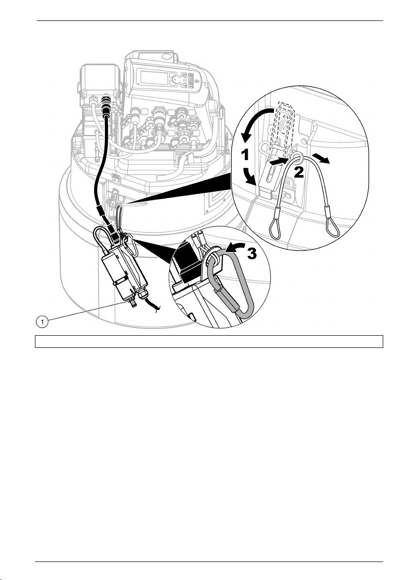
Abbildung 5 Anbringen der Trocknungsmittel-Anschlussdose – AS950 tragbarer
Probenehmer
1 Verschlusskappe
Nullpegel-Kalibrierung
Führen Sie vor der Installation des Sensors eine Nullpegel-Kalibrierung durch, falls mindestens eine
der folgenden Aussagen zutrifft.
• Bei dem Installationsort handelt es sich um einen trockenen Kanal.
• Es ist nicht möglich, in der Strömung einen genauen Pegel zu erfassen, da der Pegel sich zu
schnell ändert.
• Es ist nicht möglich, in der Strömung einen genauen Pegel zu erfassen, da physikalische
Gefahren vorliegen.
Hinweis: Der Sensor ist für den angegebenen Messbereich und die Temperatur werkseitig kalibriert.
Nullpegel-Kalibrierung (Durchfluss-Logger der FL Serie oder Probenehmer)
Führen Sie für die Nullpegel-Kalibrierung bei dem FL900 Durchfluss-Logger eine NullpegelKalibrierung (Null-Kalibrierung in Luft) mit dem Einrichtungsassistenten von FSDATA Desktop durch.
Anleitungen finden Sie in der Dokumentation zu FSDATA Desktop. Alternativ können Sie eine
manuelle Nullpegel-Kalibrierung (Null-Kalibrierung in Luft) mit FSDATA Desktop durchführen.
Anleitungen zur Durchführung einer Nullpegel-Kalibrierung bei dem FL1500 Durchfluss-Logger oder
dem Probenehmer finden Sie in der Dokumentation zum FL1500 Durchfluss-Logger bzw. zum
Probenehmer. Wenn der Sensor mit einem FL1500 Durchfluss-Logger verbunden ist, können Sie die
Nullpegel-Kalibrierung alternativ mit dem Einrichtungsassistenten von FSDATA Desktop durchführen.
Deutsch
91
Page 92

Stellen Sie sicher, dass der Sensor sich außerhalb des Wassers und auf einer flachen, ebenen,
horizontalen Fläche befindet.
Hinweis: Wenn der Sensor ausgetauscht oder für Wartungsarbeiten entfernt wird, sowie bei einem Wechsel zu
einem anderen Gerät, führen Sie bitte eine Nullpegel-Kalibrierung durch.
Nullpegel-Kalibrierung (Sigma 910 bis 950 Durchflussmessgeräte)
Führen Sie die Nullpegel-Kalibrierung folgendermaßen durch:
Hinweis: Wenn der Sensor ausgetauscht oder für Wartungsarbeiten entfernt wird, sowie bei einem Wechsel zu
einem anderen Gerät, führen Sie bitte erneut eine Nullpegel-Kalibrierung durch.
1. Verbinden Sie das Durchflussmessgerät mit einem Computer mit der InSight Software.
Anleitungen finden Sie in der Dokumentation zum Durchflussmessgerät.
2. Starten Sie die InSight Software auf dem Computer.
3. Wählen Sie „Remote Programming“ (Fernprogrammierung).
4. Wählen Sie in der Liste „Real Time Operations“ (Echtzeitvorgänge) den Tiefensensor aus.
5. Nehmen Sie die Sonde aus der Flüssigkeit, und legen Sie den Sensor mit der Sensorfläche (der
Platte mit den Öffnungen) nach unten flach auf den Tisch oder Boden.
6. Klicken Sie im Dialogfeld auf „OK“, wenn der Vorgang abgeschlossen ist.
Anbringen des Sensors an das Befestigungsband
Befestigungsbänder haben vorgebohrte Löcher, um den Sensor direkt an dem Band zu befestigen.
Weitere Informationen zum Befestigen des Sensors am Befestigungsband entnehmen Sie den
entsprechenden Schritten und Abbildungen.
Hinweis: Wenn es sich um einen mit Öl zu füllenden Sensor handelt, vergewissern Sie sich, dass der Sensor mit
Öl gefüllt ist, bevor Sie ihn am Befestigungsband anbringen. Informationen dazu entnehmen Sie dem Abschnitt
„Sensoröl einfüllen“ in diesem Handbuch.
1. Befestigen Sie den Sensor am Federring (Abbildung 6). Befestigen Sie den Sensor so, dass der
Drucksensor über die Kante des Rings hinausragt.
2. Verlegen Sie das Kabel entlang der Kante des Bandes (Abbildung 6).
3. Befestigen Sie das Kabel mit Kabelbindern aus Nylon am Befestigungsband.
Das Kabel sollte am Scheitel des Rohrs oder in der Nähe davon den mit Kabelbindern befestigten
Bereich verlassen.
Hinweis: Wenn sich eine große Menge Schlick am Boden des Rohrs befindet, drehen Sie das Band, so dass
sich der Sensor außerhalb des Schlicks befindet (Abbildung 8 auf Seite 95). Vergewissern Sie sich, dass der
Sensor jederzeit unterhalb des erwarteten Niedrigstwasserstands bleibt. Schlick muss häufig gemessen
werden, darf aber nicht aufgewirbelt werden.
92
Deutsch
Page 93

Abbildung 6 Anbringen des Sensors an das Befestigungsband
1 Sensor 3 Sensorkabel
2 Federring 4 Schrauben (2)
Platzieren des Sensors und Befestigungsbandes im Rohr
1. Platzieren Sie den Sensor im Durchfluss. In Abbildung 7 ist eine gewöhnliche Konfiguration
stromaufwärts, eine gewöhnliche Konfiguration stromabwärts und eine Konfiguration
stromabwärts mit umgekehrtem Sensor dargestellt.
Um die beste Konfiguration für den Standort zu finden, lesen Sie Tabelle 1. Weitere
Informationen zu Konfigurationen entnehmen Sie dem entsprechenden Logger-Handbuch.
2. Schieben Sie das Befestigungsband so weit wie möglich in das Rohr, um Auswirkungen durch
ein Rohrende zu vermeiden.
3. Platzieren Sie den Sensor an der Rohrsohle des Kanals. Wenn übermäßig viel Schlick am Boden
des Rohrs vorhanden ist, drehen Sie das Band im Rohr, bis der Sensor sich außerhalb des
Schlicks befindet. Siehe Abbildung 8.
Deutsch
93
Page 94

Abbildung 7 Sensorpositionen
1 Stromaufwärts, dem Fluss
zugewendet
2 Stromabwärts, dem Fluss
zugewendet
3 Stromabwärts, vom Fluss
abgewandt
Tabelle 1 Auswahl der Sondenrichtung
Optionen Beschreibung
1 Stromaufwärts Für die meisten Anwendungen empfohlen. Der Massenstrom über den Sensor sollte so
2 Stromabwärts Verwenden Sie diese Option, wenn der Sensor stromabwärts vom Messpunkt befestigt ist
3 Stromabwärts
(umgekehrter
Sensor)
gerade wie möglich verlaufen, ohne Gefälle oder Biegungen nahe dem Messpunkt.
Befestigen Sie den Sensor mit der geschrägten Kante gegen die Fließrichtung des
Medienstromes an der Messstelle.
(an dem Punkt, an dem der Medienstrom den Standort verlässt). Diese Option ist nützlich,
wenn mehr als ein Massenstrom an einem Standort ankommt und der kombinierte
Durchfluss aller Ströme an einem einzelnen Austrittspunkt gemessen wird. Diese Option
kann auch verwendet werden, wenn die Hydraulik verhindert, dass der Sensor in einem
Bereich stromaufwärts befestigt werden kann.
Befestigen Sie den Sensor so, dass er dem Fluss entgegen weist.
Verwenden Sie diese Option, wenn Option 2 aufgrund ungleichmäßigen Durchflusses im
Gewölbe nicht funktioniert. Bei dieser Art der Installation beträgt der maximale
Geschwindigkeitsmesswert 1,524 m/s (5 Fuß/s), wenn das AV9000 Schnittstellenmodul
nicht verwendet wird. Befestigen Sie den Sensor stromabwärts. Der Hersteller empfiehlt,
die Geschwindigkeit zu verifizieren, indem der Durchfluss profiliert und ggf. ein
Multiplikator für die Geschwindigkeit am Standort verwendet wird, um genauere
Messungen zu erhalten.
Hinweis: Wenn Sie das AV9000 Schnittstellenmodul und den Eintauch-AV-Sensor mit dem
FL900 Logger verwenden, können Sie im Menü „Sensor Port Set Up“ (Einstellungen Sensoranschluss)
die Option „Reversed Sensor“ (Umgekehrter Sensor) auswählen.
94 Deutsch
Page 95

Abbildung 8 Vermeiden von Schlick bei Montage des Sensors
1 Wasser 3 Sensor
2 Rohr 4 Schlick
Betrieb
Falls der Sensor mit einem FL900 Durchfluss-Logger verbunden ist, schließen Sie zum
Konfigurieren, Kalibrieren und Erfassen von Sensordaten einen Computer mit der FSDATA Desktop
Software an den Durchfluss-Logger an. Informationen zum Konfigurieren, Kalibrieren und Erfassen
von Sensordaten finden Sie in der Dokumentation zu FSDATA Desktop.
Falls der Sensor mit einem FL1500 Durchfluss-Logger verbunden ist, finden Sie die Informationen
zum Konfigurieren, Kalibrieren und Erfassen von Sensordaten in der Dokumentation zum
FL1500 Durchfluss-Logger. Alternativ können Sie zum Konfigurieren, Kalibrieren und Erfassen von
Sensordaten einen Computer mit der FSDATA Desktop Software an den Durchfluss-Logger
anschließen. Informationen zum Konfigurieren, Kalibrieren und Erfassen von Sensordaten finden Sie
in der Dokumentation zu FSDATA Desktop.
Falls der Sensor mit einem AS950 Probenehmer verbunden ist, finden Sie die Informationen zum
Konfigurieren, Kalibrieren und Erfassen von Sensordaten in der Dokumentation zum
AS950 Probenehmer.
Falls der Sensor mit einem Sigma 910, 911, 920, 930 oder 940 Durchflussmessgerät verbunden ist,
schließen Sie zum Konfigurieren, Kalibrieren und Erfassen von Sensordaten einen Computer mit der
InSight Software an das Sigma Durchflussmessgerät an.
Installieren der Software
Stellen Sie sicher, dass die aktuelle Version der FSDATA Desktop Software oder gegebenenfalls der
InSight Software auf dem Computer installiert ist. Laden Sie die Software von
http://www.hachflow.com herunter. Klicken Sie auf „Support“, und wählen Sie dann „Software
Downloads“.
Deutsch
95
Page 96

Konfigurieren des Sensors
Konfigurieren Sie Sensoren, die mit einem FL900 Durchfluss-Logger verbunden sind, mit dem
Einrichtungsassistenten von FSDATA Desktop. Anleitungen finden Sie in der Dokumentation zu
FSDATA Desktop.
Bei Sensoren, die mit einem FL1500 Durchfluss-Logger oder einem AS950 Probenehmer verbunden
sind, finden Sie die Informationen zur Konfiguration in der Dokumentation zum FL1500 DurchflussLogger bzw. zum Probenehmer. Bei Sensoren, die mit einem FL1500 Durchfluss-Logger verbunden
sind, können Sie die Konfiguration alternativ mit dem Einrichtungsassistenten von FSDATA Desktop
durchführen.
Bei Sensoren, die mit einem Sigma Durchflussmessgerät verbunden sind, befolgen Sie bitte die
Schritte in Pegelkalibrierung bei Sigma Durchflussmessgeräten auf Seite 96.
Hinweis: Wenn ein Sensor ausgetauscht oder für Wartungsarbeiten entfernt wird, sowie bei einem Wechsel zu
einem anderen Gerät, führen Sie bitte eine Pegelkalibrierung durch.
Pegelkalibrierung bei Sigma Durchflussmessgeräten
1. Wenn der Sensor im Durchfluss montiert ist, überwachen Sie den aktuellen Status mit einem PC
mit InSight-Software oder einer Durchflussmesseranzeige.
2. Messen Sie den Abstand vom Scheitel des Rohrs bis zur Wasseroberfläche mit einem Maßband.
Siehe Abbildung 9.
3. Ziehen Sie das Ergebnis aus Schritt 2 vom Rohrdurchmesser ab. Siehe Abbildung 9.
Das Ergebnis ist der Wasserspiegel. Siehe Abbildung 9.
4. Verwenden Sie die Funktion „Adjust Level“ (Höhe anpassen) der Software, um den physisch
gemessenen Wasserspiegel einzugeben.
Abbildung 9 Messen des Wasserspiegels
1 Wasserspiegel
96 Deutsch
Page 97

Wartung
V O R S I C H T
Mehrere Gefahren. Nur qualifiziertes Personal sollte die in diesem Kapitel des Dokuments
beschriebenen Aufgaben durchführen.
Reinigen des Sensors
Reinigen Sie den Sensoranschluss, wenn:
• Unerwartete Zu- oder Abnahmen bei Durchfluss- oder Pegeltrends auftreten
• Pegeldaten falsch sind oder fehlen, aber Geschwindigkeitsdaten gültig sind
• Sich zwischen dem Drucksensor und der Schutzabdeckung übermäßige Schlickablagerungen
gebildet haben
Hinweise
• Berühren Sie den Schallgeber nicht. Dadurch würde er beschädigt, und der Sensorbetrieb wäre
fehlerhaft.
• Verwenden Sie nur geeignete Reinigungslösungen, wie sie in Tabelle 2 aufgeführt sind. Reinigen
Sie den Drucksensor nicht mit einer Bürste oder einem Lappen. Dadurch würde er beschädigt,
und der Sensorbetrieb wäre fehlerhaft. Wenn Ablagerungen vorhanden sind, besprühen Sie die
Membran mit Wasser und verwenden Sie ein Wattestäbchen, um die Ansammlungen vorsichtig zu
entfernen.
• Wenn eine Dichtung beschädigt ist oder fehlt, bringen Sie eine neue an. Eine beschädigte oder
fehlende Dichtung führt zu fehlerhaften Messungen.
• Nachdem Sie den Sensor gereinigt haben, reinigen Sie die Dichtung und die Schutzabdeckung,
bevor Sie sie wieder anbringen.
• Nachdem Sie einen ölgefüllten Sensor gereinigt haben, füllen Sie das Sensoröl auf.
• Wenn ein Sensor für längere Zeit aus dem Betrieb genommen werden muss, lagern Sie ihn nicht
auf einem trockenen Regal. Der Hersteller empfiehlt, den Sensor mit dem Sensorkopf in einem
Eimer Wasser zu lagern, um zu verhindern, dass Ölablagerungen den Drucksensorkanal
verkrusten.
So reinigen Sie den Sensor:
1. Weichen Sie den Sensor in seifigem Wasser ein.
2. Drehen Sie die Schrauben aus der Schutzabdeckung. Siehe Abbildung 10.
3. Entfernen Sie die Abdeckung und die Dichtung. Siehe Abbildung 10.
4. Schwenken Sie den Sensor vorsichtig in einer geeigneten Reinigungslösung, um Schmutz zu
entfernen. Waschen Sie stärkere Ablagerungen mit einer Spritz- oder Quetschflasche ab.
5. Reinigen Sie die Dichtung und die Abdeckung.
6. Bringen Sie die Dichtung und die Abdeckung an. Ziehen Sie die Schrauben an, bis die Dichtung
zusammengedrückt wird.
Deutsch
97
Page 98

Abbildung 10 Schutzabdeckung des Sensors und Dichtung
1 Schutzabdeckung 2 Dichtung 3 Sensor
Tabelle 2 Geeignete und ungeeignete Reinigungslösungen
Geeignet Nicht verwenden
Spülmittel in Wasser Konzentriertes Bleichmittel
Fensterreiniger Kerosin
Isopropylalkohol Benzin
verdünnte Säuren aromatische Kohlenwasserstoffe
Auswechseln des Trocknungsmittels
H I N W E I S
Verwenden Sie den Sensor nicht ohne Trocknungsmittelkügelchen und nicht mit grünen
Trocknungsmittelkügelchen. Andernfalls kann der Sensor permanent beschädigt werden.
Wechseln Sie das Trocknungsmittel sofort aus, wenn es sich grün färbt. Siehe Abbildung 11.
Hinweis: Die Trocknungsmittel-Anschlussdose muss nicht vom Trocknungsmittelkern abgenommen werden, um
neues Trocknungsmittel einzufüllen.
Achten Sie bei Schritt 5 von Abbildung 11 darauf, dass der O-Ring sauber ist und weder Schmutz
noch Ablagerungen aufweist. Untersuchen Sie den O-Ring auf Risse, Dellen und sonstige Zeichen
einer Beschädigung. Tauschen Sie den O-Ring im Fall einer Beschädigung aus. Fetten Sie trockene
oder neue O-Ringe ein, um die Installation zu erleichtern. Dies verbessert auch die Dichtung und
verlängert die Lebensdauer des O-Rings.
Achten Sie darauf, dass Sie den Trocknungsmittelbehälter vertikal mit der Verschlusskappe nach
unten installieren, damit die beste Leistung erzielt werden kann. Siehe Anbringen der
Trocknungsmittel-Anschlussdose auf Seite 89.
Hinweis: Wenn die Kügelchen sich gerade grün verfärben, können sie u. U. durch Erhitzen regeneriert werden.
Nehmen Sie die Kügelchen aus dem Behälter, und erhitzen Sie sie bei 100-180 °C (212-350 °F), bis sie orange
werden. Erhitzen Sie nicht den Behälter. Wenn sich die Kügelchen nicht orange verfärben, müssen Sie durch
neues Trocknungsmittel ersetzt werden.
98
Deutsch
Page 99

Abbildung 11 Auswechseln des Trocknungsmittels
Ersetzen der hydrophoben Membran
Ersetzen Sie die hydrophobe Membran, wenn:
• Unerwartete Zu- oder Abnahmen bei Pegeltrends auftreten
• Pegeldaten falsch sind oder fehlen, die Geschwindigkeitsdaten jedoch gültig sind
• Die Membran gerissen ist oder sich mit Wasser oder Fett vollgesogen hat
Führen Sie zum Ersetzen der Membran die folgenden bebilderten Schritte aus. Achten Sie bei
Schritt 4 darauf, dass folgendes zutrifft:
• Die glatte Seite der hydrophoben Membran liegt an der Innenfläche des
Trocknungsmittelbehälters an.
• Die hydrophobe Membran ist nach oben gebogen und lässt sich ganz in das Gewinde einführen,
sodass sie nicht mehr zu sehen ist.
• Die hydrophobe Membran dreht sich mit dem Nippel mit, wenn sich der Nippel im
Trocknungsmittelbehälter dreht. Wenn sich die Membran nicht dreht, ist sie beschädigt. Führen
Sie den Vorgang noch einmal mit einer neuen Membran durch.
Achten Sie darauf, dass Sie den Trocknungsmittelbehälter vertikal mit der Verschlusskappe nach
unten installieren, damit die beste Leistung erzielt werden kann. Siehe Anbringen der
Trocknungsmittel-Anschlussdose auf Seite 89.
Deutsch
99
Page 100

100 Deutsch
 Loading...